![Advanced Material Technology±MT[0-33-3].pdf · Material Technology Technology. Advanced Material Technology Advanced Material Technology. 3.4-16. Advanced Material Technology. Advanced](https://static.fdocuments.net/doc/165x107/5ebad08215a94a1265211c82/advanced-material-mt0-33-3pdf-material-technology-technology-advanced-material.jpg)
ADVANCED General Certifi 2015 Technology and Design
30
ADVANCED General Certificate of Education 2015 9289.05 R Technology and Design Assessment Unit A2 1 assessing Systems and Control and Product Design [AV211] TUESDAY 2 JUNE, MORNING AV211 TIME 2 hours. INSTRUCTIONS TO CANDIDATES Write your Centre Number and Candidate Number on the Answer Booklet provided and on the A3 pro forma answer pages provided. Answer two questions from either Section A, Section B or Section C. Answers to questions 1(e), 2(e), 4(c), 4(d), 5(f)(i) and (ii) and 6(i)(i) and (ii) should be made on the A3 pro forma answer pages provided. At the conclusion of the examination, attach the A3 pro forma answer pages securely to the Answer Booklet with the treasury tag supplied. INFORMATION FOR CANDIDATES The total mark for this paper is 80, including a maximum of 4 marks for quality of written communication. Marks for quality of written communication will be awarded for questions 1(f), 3(c) and 5(c). Figures in brackets printed down the right-hand side of pages indicate the marks awarded to each question or part question.
Transcript of ADVANCED General Certifi 2015 Technology and Design

ADVANCEDGeneral Certifi cate of Education
2015
9289.05 R
Technology and DesignAssessment Unit A2 1
assessingSystems and Control
andProduct Design
[AV211]TUESDAY 2 JUNE, MORNING
AV
21
1
TIME2 hours.
INSTRUCTIONS TO CANDIDATESWrite your Centre Number and Candidate Number on the Answer Booklet provided and on the A3 pro forma answer pages provided.Answer two questions from either Section A, Section B or Section C.Answers to questions 1(e), 2(e), 4(c), 4(d), 5(f)(i) and (ii) and 6(i)(i) and (ii) should be made on the A3 pro forma answer pages provided.At the conclusion of the examination, attach the A3 pro forma answer pages securely to the Answer Booklet with the treasury tag supplied.
INFORMATION FOR CANDIDATESThe total mark for this paper is 80, including a maximum of 4 marks for quality of written communication.Marks for quality of written communication will be awarded for questions 1(f), 3(c) and 5(c). Figures in brackets printed down the right-hand side of pages indicate the marks awarded to each question or part question.
9289.05 R 2
Answer either the two questions in Section A or the two questions in Section B or Section C.
Section A
Electronic/Microelectronic Systems
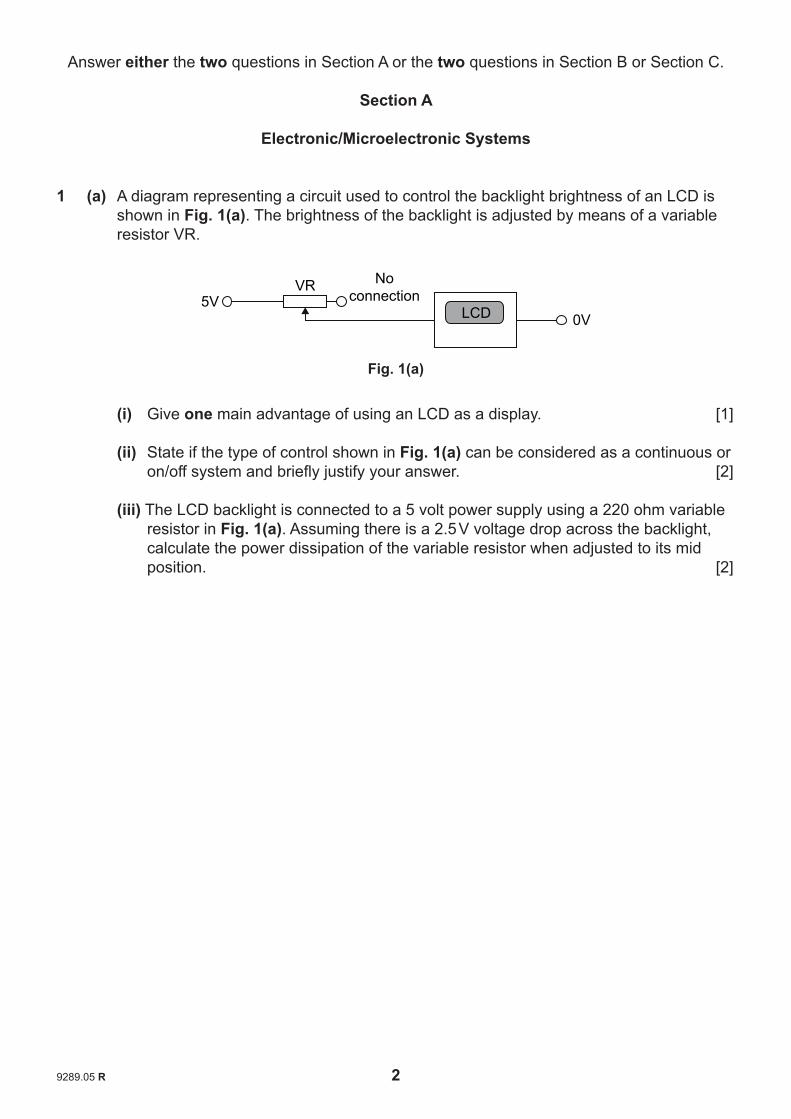
1 (a) A diagram representing a circuit used to control the backlight brightness of an LCD is shown in Fig. 1(a). The brightness of the backlight is adjusted by means of a variable resistor VR.
Fig. 1(a)
(i) Give one main advantage of using an LCD as a display. [1]
(ii) State if the type of control shown in Fig. 1(a) can be considered as a continuous or on/off system and briefly justify your answer. [2]
(iii) The LCD backlight is connected to a 5 volt power supply using a 220 ohm variable resistor in Fig. 1(a). Assuming there is a 2.5 V voltage drop across the backlight, calculate the power dissipation of the variable resistor when adjusted to its mid position. [2]
5VVR No
connection0VLCD

9289.05 R 3 [Turn over
(b) Fig. 1(b) shows a seven segment LED display which can be used as an alternative to an LCD. The seven segment LED display is a common cathode type and is connected to a decoder through resistors R1 to R7.
Fig. 1(b)
(i) State one main advantage other than cost of using an LED seven segment display compared to an LCD. [1]
(ii) Draw a circuit diagram to show how the LEDs are connected in a common cathode seven segment display. [2]
(iii) Calculate a suitable value for resistors R1– R7 in Fig. 1(b) where each LED segment requires a maximum current of 16 mA when illuminated. Assume that the forward voltage of each LED segment is 2.2 volts. [2]
(c) Part of an incomplete logic truth table for the 7 segment decoder in Fig. 1(b) is shown in Fig. 1(c) below. It shows inputs A, B, C, and D (where A is the least significant bit) with the corresponding outputs a to g for two of the displayed numbers. Determine the missing logic values. (Do not provide your answer on Fig. 1(c)). [2]
A B C D a b c d e f g1 0 1 0
1 0 1 1 1 1 1
Fig. 1(c)
5V
0V
ResistorsR1 to R7
from binarycounter
abD
C
B
A
cdefg
7 segmentdecoder
a
g
d
e c
f b

9289.05 R 4
(d) An LED display is to be used to show the speed of a mountain bicycle. A prototype system to measure the speed of the bicycle is shown in Fig. 1(d). The system makes use of two small notches cut into the existing brake disc which is attached to the axle of the wheel. When the axle rotates the notches on the disc are detected by means of an infrared transmitter and phototransistor built into the brake caliper.
Fig. 1(d)
(i) Briefly describe one main advantage and one main disadvantage of using an infrared transmitter and phototransistor for the application outlined above. [2]
(ii) Using an annotated circuit diagram, show how an infrared transmitter and a phototransistor could be connected to a 5 volt power supply to provide a pulse with the following characteristics:
• low/zero voltage when the brake disc blocks the infrared transmitter • high/5 volts when the notch is aligned with the transmitter and receiver. [4]
(iii) Draw a graph with labelled axes to show how the output voltage from your circuit in part (d)(ii) above changes as the disc rotates through 360 degrees from the position shown in Fig. 1(d). [3]
infraredtransmitter
wheel axle
phototransistor180°
0°
brakecaliper
brake disc

9289.05 R 5 [Turn over
(e) Part of a proposed circuit design for the bicycle speedometer is shown in Fig. 1(e) where the pulses from the phototransistor in Fig. 1(d) are to be counted for a period
of 1 second and the speed in kph (kilometres per hour) is then to be displayed for 2 seconds on two LED seven segment displays. i.e. the display is effectively ‘refreshed’
every 3 seconds. During testing it was noted that when the brake disc rotated at 1 revolution per second the corresponding bicycle speed was 6 kph.
Fig. 1(e)
Using annotated electronic circuit diagrams on the blank pro forma provided (answer number 1(e)) design a circuit for the bicycle speedometer that will repeatedly detect
the pulses from the phototransistor for 1 second and display the speed in kph for 2 seconds. (If your solution is PIC based it should be accompanied by a flow chart program.) [10]
(f) When selecting the infrared transmitter and phototransistor to act as a sensor to detect the rotation of the brake disc in Fig. 1(d) the designer considered a number of factors, e.g. whether a contact or non contact sensor would best suit the application. Discuss three other main factors that designers must consider when choosing the most suitable sensor for any particular application. Provide two different specific examples, other than the one shown in Fig. 1(d) that clearly illustrate how these factors influence the selection of a sensor. [5]
Quality of written communication [4]
7 segmentdecoder
7 segmentdecoder

9289.05 R 6
2 The voltage divider circuit shown in Fig. 2(a) is to be used as part of a circuit for measuring the air temperature in a greenhouse. The resistance/temperature characteristic for the thermistor Rt is also shown.
Fig. 2(a)
(a) (i) Draw the circuit symbol for the thermistor referred to in Fig. 2(a). [1]
(ii) Explain the purpose of a voltage divider circuit. [2]
(iii) Sketch a graph with labelled axes showing how the output Vo in Fig. 2(a) varies as the temperature changes. [2]
(iv) If the air temperature in the greenhouse varies between 10°C and 30°C on a given
day, calculate the corresponding voltage range for Vo in Fig. 2(a). [2]
(b) A greenhouse temperature display is to be made by using the voltage Vo from the voltage divider in Fig. 2(a) connected to a voltmeter by means of an amplifier based on an op amp as shown in Fig. 2(b). It is required that the voltage displayed by the meter, in volts, should represent the temperature in °C. During tests it was noted that Vo ranged from 4 volts at 0°C to 2 volts at 40°C.
voltage divider op amp voltmeter
Fig. 2(b)
Draw and label a differential amplifier to meet this requirement showing clearly how the voltage divider and voltmeter would be connected. Also determine suitable values for Rf and Ri, where Rf is the feedback resistor and the gain for a differential amplifier is Rf/Ri. [6]
6V
Vo
R
(kΩ)
R1 10 kΩ 10
8
6
4
0° 10° 20°Temp (°C)
30° 40°
Rt
0V

9289.05 R 7 [Turn over
(c) A water storage tank used to irrigate the greenhouse is filled through a solenoid operated inlet valve as shown in Fig. 2(c). When the water in the tank falls below a
certain level the inlet valve is opened and the tank is refilled. A float arrangement operates upper and lower limiting microswitches which are also shown in Fig. 2(c).
Fig. 2(c)
(i) Show with the aid of an annotated circuit diagram how the microswitch shown in Fig. 2(c) could be used in conjunction with other components to provide a logic ‘1’ input to a digital input of a PIC when operated by the float. [2]
(ii) Show with the aid of an annotated circuit diagram, how a 24 volt solenoid, in conjunction with other components, could be connected to the output of a PIC to enable it to be opened by a logic ‘1’ on a digital output. [2]
(iii) A PIC with two digital inputs (I/P1 and I/P2) and one digital output (O/P1) is to be employed to control the solenoid inlet valve on the water storage tank in Fig. 2(c). Assume that when operated the microswitches provide a logic ‘1’ at the inputs of the PIC and that the solenoid is connected to the output of the PIC to enable it to be opened by a logic ‘1’ on the output.
Using the minimum number of commands, write a fl ow chart program that will refi ll the tank when necessary, i.e. when the lower limiting microswitch is operated. (assume microswitch 1 is connected to I/P1 and microswitch 2 is connected
to I/P2) [4]
solenoidinlet valve
floatguide
microswitch 1(upper limit)
microswitch 2(lower limit)
water outlet to greenhouse
float
1
1
microswitch detailand symbol
2
2
33

9289.05 R 8
(d) A logic circuit used to control artificial lighting in the greenhouse has logic inputs from three environmental sensors S1, S2 and S3 as shown in Fig. 2(d). A logic ‘1’ from the output Q of the logic circuit will switch the artificial lighting on. The lighting must be switched on only under the following conditions: S1 AND S3 only high, S1 AND S2 only high, S2 AND S3 only high, S2 only high.
Fig. 2(d)
(i) Draw a truth table showing the logic inputs S1, S2 and S3 from the sensors and the output Q to control the artifi cial lighting. [4]
(ii) Use a Karnaugh Map to determine a minimised logic expression for the output Q. [3]
(iii) Draw a logic circuit that will produce the required output Q. [2]
5V
0V
S3
S2
S1 LogicCircuit
output Q to lighting circuit

9289.05 R 9 [Turn over
(e) A humidity sensor and DC motor are shown in Fig. 2(e). The sensor provides an analogue output voltage which is directly proportional to the humidity in a greenhouse. The output voltage of the sensor varies from 0 to 5 volts as the humidity ranges from 0% to 100%. The 12 volt DC motor is to be used to drive a fan in order to ventilate the greenhouse to reduce humidity levels when necessary. The DC motor is to be run at high speed or low speed as required.
Fig. 2(e)
A PIC with an analogue input is to be used to periodically ‘read’ the humidity sensor and in turn control the DC motor. The voltage range of the analogue input is 0 to 5 volts and the corresponding digital range is 0 to 255.
Using annotated electronic circuit diagrams (on the blank pro forma provided (answer number 2(e)) design a PIC based circuit and associated flow chart program that will fulfil the following:
• Check the humidity level every 4 minutes.
• If the humidity level is equal to or above 60%, switch the fan on at full speed until the humidity level is equal to or below 40% at which point the fan should switch to low speed.
• If the humidity level is equal to or below 20% the fan should switch off. [10]
5V
0V
12V
0V
Humiditysensor output voltage M

9289.05 R 10
Answer either the two questions in Section B or the two questions in Section A or Section C.
Section B
Mechanical and Pneumatic Control Systems
3 Fig. 3 (a)(i) shows an image of a prototype helicopter that can be used to transport people. The helicopter contains a range of mechanical and hydraulic components and is powered by an engine.
Main Rotor
Rear Rotor
Fig. 3(a)(i)
(a) (i) Outline two main safety issues associated with mechanical systems. [2]
(ii) The prototype helicopter uses a taper bearing to support the transmission shaft on the main rotor. In your answer booklet draw a suitable taper bearing arrangement for the transmission shaft shown in Fig. 3(a)(ii). Please note that signifi cant radial and axial forces are present. Show how the bearing is secured in position and includes provision for lubrication. [5]
Main Rotor Main Rotor
TransmissionShaft
Shell of HelicopterCabin
Bearing Location
Engine
Fig. 3(a)(ii)
© Svetlana Polushkina/ iStock / Thinkstock

9289.05 R 11 [Turn over
(iii) Briefl y describe two main characteristics associated with using a roller bearing in comparison to a self-aligning bearing. Exclude any reference to radial and axial loads. [2]
(b) (i) The prototype helicopter is transported for maintenance on a trolley. A cantilever brake is engaged on the trolley as a means of control. In your answer booklet draw an annotated sketch outlining the main features of a typical cantilever braking system that could be used on the trolley. [3]
(ii) The winch shown in Fig. 3(b)(ii) has been added to the helicopter for assisting with lifting loads. The winch hook lifts a load with a mass of 65 kg up a vertical height which gains 7021.3 J in potential energy before coming to rest. Calculate
the vertical height the load is lifted. Assume g = 9.82 m/s2. [3]
Fig. 3(b)(ii)
(iii) Calculate the minimum power to be provided to the winch system in order for the winch output shaft to lift the hook 3 metres in 30 seconds if the gravitational force on the hook is 800 N. Assume a 25% loss of power due to friction. [3]
(iv) The output torque from the main transmission shaft is 260 N m. Assuming no power loss, calculate the power from the main transmission shaft of the helicopter if it rotates at 1400 rev/min. [3]
(c) Refuelling of helicopters and light aircraft is often supplied by a small tanker lorry. The lorry contains a clutch to transmit motion from the crankshaft in the engine to the driveshaft.
Discuss one main advantage and one main disadvantage of each of the following clutches: diaphragm and centrifugal. Justify the choice of hydraulic activation as a method employed to activate the lorry clutch. [5]
Quality of written communication [4]
Winch
Hook
© Edsisonphotos/ iStock / Thinkstock

9289.05 R 12
(d) In your answer booklet design, draw and annotate a mechanical system that would achieve each of the following requirements:
(i) A means by which the lid of the fi rst aid box stored on the helicopter can be secured down as shown in Fig. 3(d)(i). The mechanism must be quick release, attached to the main casing and must be secured within the locking area. [4]
Fig. 3(d)(i)
(ii) A means of enabling the platform in Fig. 3(d)(ii) to be raised and lowered to a
suitable height by the operator when carrying out routine maintenance on engine components on the helicopter. The mechanism must be manually operated, secured underneath the platform and have a suitable means of locking the platform at a set height. Your solution must be attached to the pivot points and base. [6]
EngineComponents
PLATFORM
BASE
Pivot Point Pivot Point
Fig. 3(d)(ii)
SIDE VIEW
AluminiumLid
3D VIEWLOCKING
AREA Aluminiummain
casing

BLANK PAGE
(Questions continue overleaf)
9289.05 R 13 [Turn over

9289.05 R 14
4 (a) (i) The double acting cylinder in Fig. 4(a)(i) has a stroke length of 400 mm and is calculated to exert a force during the outstroke of 600 N. Calculate the work
done. [1]
Fig. 4(a)(i)
(ii) Open and closed loop systems are used in pneumatic circuits. With reference to a specifi c pneumatic example of your choice, distinguish between an open and closed loop system. [2]
(iii) The double acting cylinders B1, B2, B3 and B4 in Fig. 4(a)(ii) operate with an air pressure of 0.4 N/mm2 with each producing a force of 1538.6 N during the outstroke. It is intended to replace B1, B2, B3 and B4 with one large double acting cylinder. Calculate the piston radius of this replacement double acting cylinder which will operate at the same air pressure and produce the same overall force. Assume = 3.14. [3]
Fig. 4(a)(ii)
(b) (i) With reference to the data below calculate the air consumption in litres for the double acting cylinder shown in Fig. 4(b)(i) below for one complete cycle: [5]
D = 80 mm S = 300 mm d = 25 mm Working Pressure = 5 Bar Assume = 3.14
Fig. 4(b)(i)
(ii) Proximity sensors are used on a range of pneumatic systems. Explain the principle of operation of a proximity sensor. [2]
(iii) O-rings are used to seal the piston inside a double acting cylinder. Give two main advantages of using O-rings as seals. [2]
B1 B2 B3 B4
D
S
d

9289.05 R 15 [Turn over
(c) Pro forma 4(c) shows a pneumatic system used in a soft drinks management system. On the pro forma provided (answer number 4(c)) draw a suitable sequential pneumatic circuit to achieve the desired sequence outlined. The sequence must be completed as follows:
• The start valve is activated to begin the sequence. With a keg in position cylinder A will go positive to place the keg below TANK 1. This will activate the air bleed to make cylinder W go negative, emptying some of the contents of TANK 1 into the keg. Following detection by the 3/2 valve a time delay will begin and cylinder W will go positive.
• Following detection by the 3/2 valve cylinder A goes negative which will be speed controlled. As cylinder A goes negative the one way roller trip will be briefly activated to make the single acting cylinder B go positive and immediately negative. This cylinder will move the keg onto the line for TANK 2 using the suction pad. The speed control of the single acting cylinder must be able to be controlled on both the positive and negative stroke.
• The keg moves along the rollers (via gravity fall) to activate the micro-switch and make cylinder X go negative, emptying some of the contents of TANK 2 into the keg. Following detection by the 3/2 valve cylinder X will go positive to close the tank and restart the sequence.
• Emergency stops can be activated from either position to stop the air supply to all 5/2 valves. [15]
(d) On the pro forma provided (answer number 4(d)) design and draw: • A pneumatic system which uses the minimum number of components to enable
cylinder N to be precisely controlled using micro-switches for the purposes of accurately loading the kegs via the suction pad. Micro-switches A and B must be connected in series to control one side of the cylinder. Micro-switches C and D must be connected in series to control the other side of the cylinder. Precision control will allow the operator to start or stop the movement of the piston at any stage as it goes positive or negative. [5]
• A pneumatic system which detects the arriving keg via the air bleed which in turn adds one to the counter before sending cylinder Z positive. The cylinder will automatically retract, without any form of physical activation, using the minimum number of components. [5]

9289.05 R 16
Answer either the two questions in Section C or the two questions in Section A or Section B.
Section C
Product Design
5 Car roof storage units like the one shown in Fig. 5 below are designed and manufactured by companies in a range of sizes, shapes, styles and budgets.
Fig. 5
(a) Market research plays an important role for any company designing and manufacturing these car roof storage units.
(i) Explain the purpose of market research. [2]
(ii) Explain why market research needs to be representative. [2]
(b) Over the last number of years the range of car roof storage units that have appeared on the market may have been partly due to incremental product developments and partly due to Technology push.
(i) Explain two main characteristics associated with incremental product developments which may have contributed to the design of products. [2]
(ii) Explain three main characteristics associated with Technology push which may have contributed to the design of products. [3]
Car roof storage unit
© Iurii Druzhynets/ iStock / Thinkstock

9289.05 R 17 [Turn over
(c) When designing products companies need to be aware of international and regional differences which exist and the impact that these may have on their business.
With reference to five different specific product examples discuss how international
and/or regional differences have influenced the design of each chosen example. [5]
Quality of written communication [4]
(d) Many models of car roof storage units have experienced the introduction, growth, maturity and decline stages of the product life cycle.
(i) Describe three main differences between the main characteristics of introduction and the main characteristics of growth. [3]
(ii) Describe three main differences between the main characteristics of maturity and the main characteristics of decline. [3]
(e) When promoting new models of car roof storage units it is important for companies to have a clear understanding of the limitations of the different promotional methods before formulating a strategy.
(i) Explain two main advantages and one main disadvantage associated with the use of sales promotion as a means of promoting the product. [3]
(ii) Explain two main advantages and one main disadvantage associated with the use of trade fairs as a means of promoting the product compared to personal selling. [3]

9289.05 R 18
(f) (i) With reference to Fig. 5(f)(i) below and using the blank A3 pro forma provided (answer number 5(f)(i) and (ii)) design graphical information which could be printed on an instruction leafl et to convey to the person fi tting and/or using the product the following information:
• The height of the garage door must be a minimum of 2.2 metres in order to provide clearance for the car with the fitted roof storage unit.
• The storage unit is designed with a maximum weight restriction of 60 kg with a recommendation of 50% of the weight in the middle, 25% on the front and the remaining 25% on the back rail.
• The storage unit should be centred on the length and width of the roof. [5]
Fig. 5(f)(i)
middle
front back
© Iurii Druzhynets/ iStock / Thinkstock

9289.05 R 19 [Turn over
(ii) The car roof storage unit shown in Fig. 5(f)(ii) is often used to carry a wide range of sporting, leisure and holiday making items. It is important that such items are fi rmly secured in position to prevent damage due to movement as a result of road conditions or driving styles.
Fig. 5(f)(ii)
Using the blank A3 pro forma provided (answer number 5(f)(i) and (ii)) produce a suitable design which will allow the user to quickly secure different sized items inside the storage unit to prevent damage during transit. Show how your design could be attached to the ABS housing of the storage unit. [5]
Dimensions of car roof storage unit
Length 1400 mmWidth 900 mmDepth 400 mm
High Impact ABShousing (3mm thickness)

9289.05 R 20
6 Fig. 6 below shows a child’s desk and chair which has been designed and manufactured by a company which focuses on domestic bedroom furniture.
Fig. 6
Many companies are aware of the environmental issues relating to the design and manufacture of products. With the rising levels of greenhouse gas emissions and the impact this may be having on climate change many feel that the solution must come from reducing the causes of increased levels of emissions.
(a) Outline two main different causes of increased levels of greenhouse gas emissions
which have resulted from human activity. [2]
(b) The work of marketing information systems (MIS) is to help businesses gain a better understanding of the market environment.
Briefly explain two main characteristics associated with each of the following tasks of the MIS:
• Product research. • Distribution research. [4]
(c) When developing a market strategy to guide the direction of the company producing domestic bedroom furniture, decisions were taken by management to consider the views of the market development and product development teams.
(i) Briefl y explain what is involved in market development and give one main reason why the management of this company might consider the team’s views as high risk. [2]
(ii) Briefl y explain what is involved in product development and give one main reason why the management of this company may look positively on the team’s views. [2]

9289.05 R 21 [Turn over
(d) When determining a suitable price for the child’s desk and chair the company considered using either the perceived value pricing method or the cost-plus pricing method.
(i) Explain what is meant by the perceived value pricing method. [2]
(ii) Briefl y outline two main problems associated with the cost-plus pricing method which may infl uence the decision of the company not to use this method. [2]
(e) As the company continually strives for improvement the role of a quality assurance process is very important.
(i) Explain one main quality assurance process that could be used by the company. [2]
(ii) Explain how this could benefi t the company on its journey of improvement. [2]
(f) Designers try to reduce material use in products in an attempt to minimise costs whilst maintaining the functional and performance characteristics.
Select two different examples of products and explain how the designer has specifically managed to reduce material use. [4]
(g) Many products incorporate social and economic factors in their design.
(i) Choose one example of a product and describe how it incorporates social factors in its design. [2]
(ii) Using a different example, describe how another product has incorporated economic factors in its design. [2]

9289.05 R 22
(h) Dyson is a designer who has revitalised many different products.
Explain two main characteristics associated with the influence of Dyson. [4]
(i) Fig. 6(i)(i) below shows a child’s desk that was designed and manufactured by a student.
Fig. 6(i)(i)
(i) During testing of the desk shown in Fig. 6(i)(i) it was found that repeated movement caused the corner of the side panels to produce scrapes and markings on tiled and wooden fl oors. In addition the desk does not remain stable on uneven surfaces.
On the blank A3 pro forma provided (answer number 6(i)(i) and (ii)) produce one suitable solution for the following:
Annotated sketches of a low cost fl oor protector that can be quickly and securely fi tted to the corners of the desk and will enable the desk to remain stable on uneven surfaces. [5]
Corner
Side panel

9289.05 R 23 [Turn over
(ii) In Fig. 6(i)(ii) below the side panel is joined to the work surface by simply drilling and securing two wood screws. During testing of the product concerns were expressed that this did not provide suffi cient support for the work surface and it lacked the aesthetic fi nesse required by this product.
On the blank A3 pro forma provided (answer number 6(i)(i) and (ii)) produce one suitable solution for the following:
Annotated sketches of a redesign to secure the side panel to the work surface to provide:
• Low cost adequate support with aesthetic appeal with minimal use of materials. [3]
Explain how your redesign would be appropriate for batch production. [2]
Fig. 6(i)(ii)
Work surface
Side panel
woodscrews
THIS IS THE END OF THE QUESTION PAPER

9289.05 R
Permission to reproduce all copyright material has been applied for.In some cases, efforts to contact copyright holders may have been unsuccessful and CCEAwill be happy to rectify any omissions of acknowledgement in future if notifi ed.

9289.02
Pro forma answer page(answer number 1(e))
Question No. 1(e)
7 segmentdecoder
seven segment displays
7 segmentdecoder
Advanced (A2) Technology And DesignAssessment Unit A2 1 Summer 2015

9289.02
Pro forma answer page(answer number 2(e))
Advanced (A2) Technology And DesignAssessment Unit A2 1 Summer 2015
Question No. 2(e)

9289.02
Pro forma answer page(answer number 4(c))
Advanced (A2) Technology And DesignAssessment Unit A2 1 Summer 2015
Question No. 4(c)
14
5 3
12
1
4 2
KEG
1 5 3
4 2 14
TANK 1
W
1 5 3
4 2 14
TANK 2
X
B
2
Emergency Stop
1
3 2
Emergency Stop
1
3
12
12
LOADING
BAY CHUTE SUCTION
PAD
14 12
5 3
14 2 4
START
VALVE
NOTE: CYLINDERS X AND W ARE DRAWN IN THE POSITIVE STROKE AT THE
START OF THE SEQUENCE
GROUP CHANGE
OVER VALVE
KEG MOVES ALONGTHE ROLLERS (VIAGRAVITY FALL)
A

9289.02
5 3
124 2
Z
14
KEG
SUCTION PAD
+12V
Micro-switch A
Micro-switch B
+12V
Micro-switch C
Micro-switch D
Counter
N
Air Bleed
2 3 41
Pro forma answer page(answer number 4(d))
Advanced (A2) Technology And DesignAssessment Unit A2 1 Summer 2015
Question No. 4(d)

9289.02
Pro forma answer page(answer number 5(f)(i) and (ii))
Advanced (A2) Technology And DesignAssessment Unit A2 1 Summer 2015
Question No. 5(f)(i) and (ii)

9289.02
Pro forma answer page(answer number 6(i)(i) and (ii))
Advanced (A2) Technology And DesignAssessment Unit A2 1 Summer 2015
Question No. 6(i)(i) and (ii)