
Advanced for LabVIEW Classic State Machines - NTS Press · 92 Chapter 4 Classic State Machines...
16
Bress book May 2, 2013 17:31 Basics State Machines 4 Classic State Machines This chapter introduces a robust design pattern called the state machine that can be used to tackle many common LabVIEW coding problems. The state machine trans- lates state transition diagrams into LabVIEW code that is readable, scalable, and maintainable. State machines are robust, flexible, and compact. They provide storage for persistent data and handle errors gracefully and efficiently. 4.1 State Machine Elements The state machine architecture organizes a VI into states and transitions. The states are the general functions and abilities of the VI—the things the VI can do. Transitions map out the ways that the VI can move from one state to another. The states are represented by individual cases in a case structure. Each case contains all of the code needed to execute the functions of its state. The case structure is placed within a loop, driving the VI from one state to another. Each state decides which state to move to next. Typically, the states are listed in a type-defined enumerated constant, and this constant is stored in a shift register on the main loop. Each loop iteration, which is the value of the enumerated constant, is read from the shift register and fed to the selector terminal of the case structure to choose the next state. When a state is completed, it places the name of the next state on the shift register. Each state is responsible for telling the state machine where to go to next. Each state must also decide if the main loop continues or terminates. This is typically done by creating a Boolean output tunnel on the main case structure and wiring it to the continuation terminal of the loop. Each state in the case structure wires a value to this tunnel to either stop the state machine or keep it running. Let’s take a look at the standard elements of a classic state machine in more detail. A basic schematic of the classic state machine is shown in Figure 4.1. In order to discuss the various elements of the state machine, we have to name them. Unfortunately, there are very few widely accepted terms in the LabVIEW community used to discuss state machine elements. This means that we have the freedom to invent our own names for use in this book. The terms “lobby” and “alley” were coined for this book. The term 90
Transcript of Advanced for LabVIEW Classic State Machines - NTS Press · 92 Chapter 4 Classic State Machines...
Bress book May 2, 2013 17:31
AdvancedArchitecturesfor LabVIEW
Basics
AdvancedArchitecturesfor LabVIEWbb
StateMachines 4
Classic State MachinesThis chapter introduces a robust design pattern called the state machine that can beused to tackle many common LabVIEW coding problems. The state machine trans-lates state transition diagrams into LabVIEW code that is readable, scalable, andmaintainable. State machines are robust, flexible, and compact. They provide storagefor persistent data and handle errors gracefully and efficiently.
4.1 State Machine ElementsThe state machine architecture organizes a VI into states and transitions. The statesare the general functions and abilities of the VI—the things the VI can do. Transitionsmap out the ways that the VI can move from one state to another.
The states are represented by individual cases in a case structure. Each casecontains all of the code needed to execute the functions of its state. The case structure isplaced within a loop, driving the VI from one state to another. Each state decides whichstate to move to next. Typically, the states are listed in a type-defined enumeratedconstant, and this constant is stored in a shift register on the main loop. Each loopiteration, which is the value of the enumerated constant, is read from the shift registerand fed to the selector terminal of the case structure to choose the next state. When astate is completed, it places the name of the next state on the shift register. Each stateis responsible for telling the state machine where to go to next.
Each state must also decide if the main loop continues or terminates. This istypically done by creating a Boolean output tunnel on the main case structure andwiring it to the continuation terminal of the loop. Each state in the case structure wiresa value to this tunnel to either stop the state machine or keep it running.
Let’s take a look at the standard elements of a classic state machine in more detail.A basic schematic of the classic state machine is shown in Figure 4.1. In order to discussthe various elements of the state machine, we have to name them. Unfortunately, thereare very few widely accepted terms in the LabVIEW community used to discuss statemachine elements. This means that we have the freedom to invent our own names foruse in this book. The terms “lobby” and “alley” were coined for this book. The term
90
Bress book May 2, 2013 17:31
Chapter 4 Classic State Machines 91
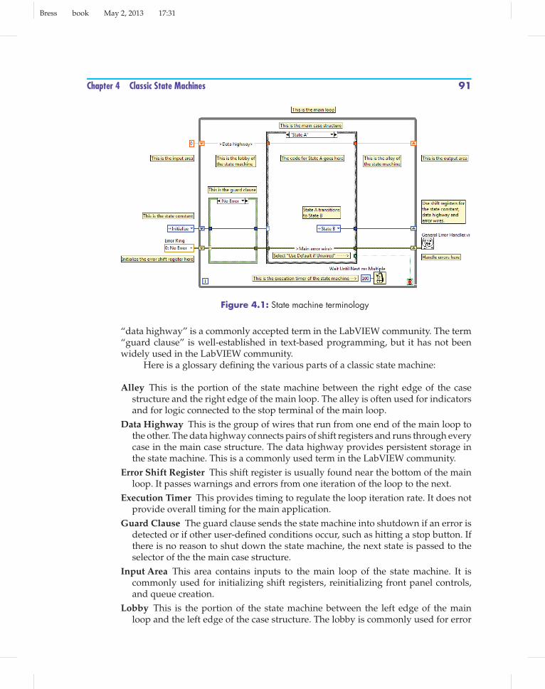
Figure 4.1: State machine terminology
“data highway” is a commonly accepted term in the LabVIEW community. The term“guard clause” is well-established in text-based programming, but it has not beenwidely used in the LabVIEW community.
Here is a glossary defining the various parts of a classic state machine:
Alley This is the portion of the state machine between the right edge of the casestructure and the right edge of the main loop. The alley is often used for indicatorsand for logic connected to the stop terminal of the main loop.
Data Highway This is the group of wires that run from one end of the main loop tothe other. The data highway connects pairs of shift registers and runs through everycase in the main case structure. The data highway provides persistent storage inthe state machine. This is a commonly used term in the LabVIEW community.
Error Shift Register This shift register is usually found near the bottom of the mainloop. It passes warnings and errors from one iteration of the loop to the next.
Execution Timer This provides timing to regulate the loop iteration rate. It does notprovide overall timing for the main application.
Guard Clause The guard clause sends the state machine into shutdown if an error isdetected or if other user-defined conditions occur, such as hitting a stop button. Ifthere is no reason to shut down the state machine, the next state is passed to theselector of the the main case structure.
Input Area This area contains inputs to the main loop of the state machine. It iscommonly used for initializing shift registers, reinitializing front panel controls,and queue creation.
Lobby This is the portion of the state machine between the left edge of the mainloop and the left edge of the case structure. The lobby is commonly used for error

Bress book May 2, 2013 17:31
92 Chapter 4 Classic State Machines
checking, for polling a stop button, as a location for inputs that need to be monitoredevery loop iteration, or for inputs needed by multiple states.
Main Case Structure The case structure is the heart of the state machine. The selectorof the case structure accepts an input that designates the next state, typically anenumerated constant. It contains the code for each state of the state machine. Eachstate is represented by a case in the case structure.
Main Error Wire The main error wire is the error-handling backbone of the statemachine. This wire runs from one end of the main loop to the other. The error wireconnects a pair of shift registers, and it runs through both the guard clause andthe main case structure. The main error wire should be sent to an error-handlingroutine after the state machine finishes.
Main Loop This is the While loop that drives the state machine. The While loopcontains shift registers for the data highway, the state constant, and the main errorwire. The conditional terminal is wired to an output of the main case structure.Each case must send either a True or False value to the conditional terminal.
Output Area This area contains the outputs of the main loop of the state machine. Itis commonly used for closing and destroying references and for error handling.
State Constant This is the constant that determines the next state to be executed. Itis typically a type definition enumerated constant or a string constant. The stateconstant is placed on a shift register to pass it on to the next iteration of the mainloop.
State Shift Register This shift register stores the value of the state constant. It allowseach state to determine which state will be executed next.
4.2 State Machine StructureThe area to the left of the main loop is the input area of the state machine. Code in theinput section that is wired to the main loop executes before the loop starts running.Wires enter the loop through tunnels or shift registers. If a wire enters the loop ata non-indexing tunnel, the value on the wire at the beginning of loop is constantthroughout the life of the loop. If a wire terminates at a shift register, the value onthe wire initializes the shift register. The input area is a natural place to put code thatinitializes shift registers, sets front panel objects to known starting states, or createsqueues (covered in Chapter 13). It is also a natural place to put items that are constantfor the duration of the loop.
The main loop is the engine that drives the state machine from one state to thenext. The main loop has shift registers devoted to storing important data known as thedata highway. It also has a shift register dedicated to transmitting error informationand the value of the next state, usually in the form of an enumerated constant thatlists the states of the state machine.
In Figure 4.1, the state shift register is initialized with the Initialize state. Thisensures that the Initialize state will be the first state executed. The data highway anderror shift registers are also initialized. Depending on the nature of the information
Bress book May 2, 2013 17:31
Chapter 4 Classic State Machines 93
on the data highway, it may or may not be necessary to initialize the data highwayshift registers. The error shift register, though, always should be initialized in a top-level VI. Uninitialized shift registers retain their data from one run of the VI to thenext as long as LabVIEW remains open on the host computer. This may be desirablein an action engine sub-VI, as we will see in Chapter 5, but it is usually undesirablefor a top-level VI. If you do not initialize the error shift register when a top-level VIstarts, an error from the last run may be read from the unitialized shift register andenter the VI during the first loop iteration. Initializing the error shift register preventsthis from happening.
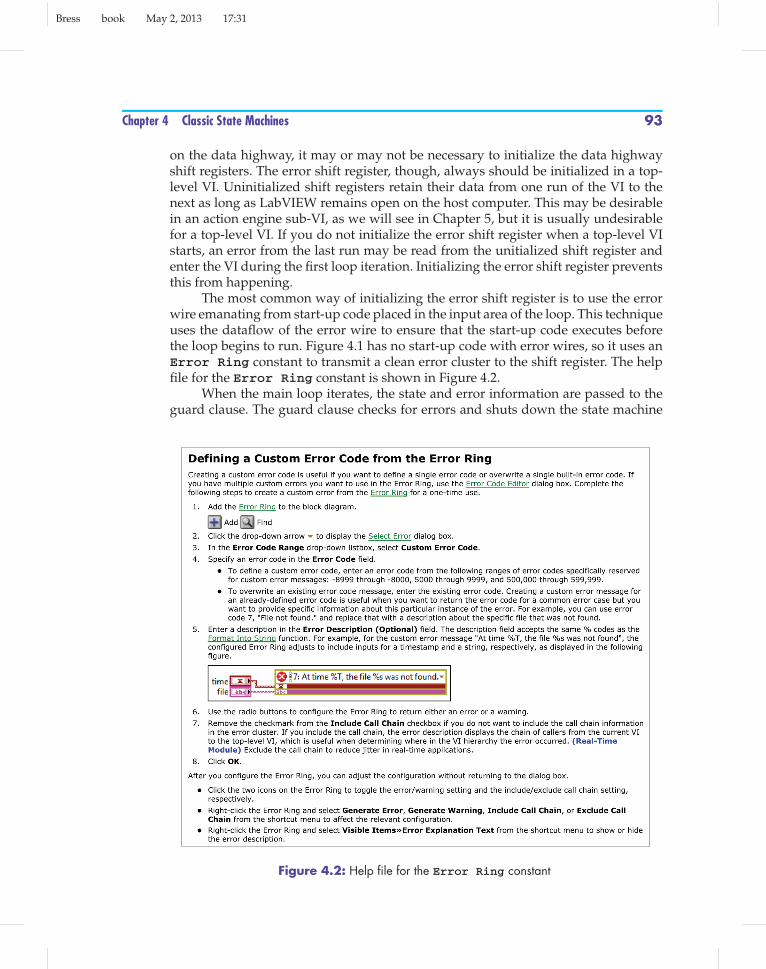
The most common way of initializing the error shift register is to use the errorwire emanating from start-up code placed in the input area of the loop. This techniqueuses the dataflow of the error wire to ensure that the start-up code executes beforethe loop begins to run. Figure 4.1 has no start-up code with error wires, so it uses anError Ring constant to transmit a clean error cluster to the shift register. The helpfile for the Error Ring constant is shown in Figure 4.2.
When the main loop iterates, the state and error information are passed to theguard clause. The guard clause checks for errors and shuts down the state machine
Figure 4.2: Help file for the Error Ring constant

Bress book May 2, 2013 17:31
94 Chapter 4 Classic State Machines
Figure 4.3: Illustration of how to use a Shutdown state to stop a state machine
if necessary. The guard clause in Figure 4.1 checks the status of the main error wire.If the error wire is clear, the guard clause passes the state information to the selectorterminal of the main case structure. This can be seen in the No Error case of the guardclause shown in Figure 4.1.
If an error is detected by the guard clause, the Shutdown state is sent to theselector of the main loop. This is illustrated in the Error case of the guard clauseshown in Figure 4.3. The guard clause is executed every loop iteration, since it is inthe lobby of the state machine. This allows the the state machine to detect and respondto errors one loop iteration after the error occurs.
The guard clause is in the lobby of the state machine. The lobby contains codethat executes every loop iteration before the main case structure executes. This makesit a good location for code that must be updated frequently to provide inputs for themain case structure. Be careful, though, code in the lobby executes before the maincase structure only if dataflow demands it.
The main case structure is the heart of the state machine. Each state is representedby a case in the case structure. The code necessary to execute the state is placed inthe case representing that state. Each case of the case structure also determines whichstate to execute next and places the appropriate value of the state constant on the stateshift register.
Each state must also decide whether to continue or terminate the main loop. TheShutdown state, shown in Figure 4.3, wires a Boolean True to the conditional terminalof the main loop using an output tunnel in the main case structure. Every case of thecase structure must wire a value to this output tunnel. One way to do this would beto wire a Boolean False constant to this tunnel in every case other than the Shutdownstate. A simpler method is to enable the Use Default If Unwired option for the outputtunnel, since the default value for a Boolean is False.

Bress book May 2, 2013 17:31
Chapter 4 Classic State Machines 95
Wiring Tip: Be careful with the Use Default If Unwired option. The visual cueon the output tunnel is easy to miss and might lead to confusion, degradingreadability. Stopping a loop is one of the acceptable uses of this option. Whena reader flips through the cases of the case structure, the Boolean True in theShutdown state jumps out because it is the only value explicitly wired to thetunnel. This increases the readability of the code and is a common enough usethat the danger of confusion is minimal.
Code in the alley of the state machine executes when the code in the main casestructure is finished. The code in the alley is executed every loop iteration, so it is agood location to put indicators that must be frequently updated from data generatedby multiple states. Code in the alley of the state machine executes after the main casestructure only if dataflow demands it.
With proper dataflow dependence, code in the lobby executes before the maincase structure, and code in the alley executes after the main case structure. Codein the lobby often creates input tunnels to the main case structure, while code inthe alley often flows from output tunnels from the main case structure. Inputtunnels to a case structure can be used or ignored by the individual cases in thestructure, but every case must output values to every output tunnel in a casestructure.
Sometimes this can lead to difficulties. The Shutdown case shown in Figure 4.3sends a Boolean True to the stop terminal of the of the main loop. Even though therewill be no more state transitions, something must be wired to the enumerated constantoutput tunnel or the VI will not run. The Shutdown state was chosen because it is theleast confusing choice in this situation.
State machines often require loop timing control. One choice for controllingthe loop speed is the Wait Until ms Multiple function, which was discussedin Chapter 1. This function provides a variable waiting time, ensuring that the loopperiod is equal to the wired value in milliseconds (if possible). If the duration of thecode within the loop exceeds the time target, the period will be set to the nearestmultiple of the time target. This function also “puts LabVIEW to sleep” during thewaiting period. The CPU is released by LabVIEW to perform other tasks during thewait period.
When the main loop has ended, the code in the output section of the state machineis executed. This is a natural place to put error-handling code. It is also a good placeto close references, release resources, and do whatever else is needed to shut downthe VI gracefully.
State machines often require storage for important data. This storage is providedby the data highway. The data highway is a wire (or group of wires) that connectspairs of shift registers at the top of the main loop. The shift registers ensure that dataon the data highway is stored from one loop iteration to the next. The data highwayruns through the main case structure, making it available to every state in the statemachine.

Bress book May 2, 2013 17:31
96 Chapter 4 Classic State Machines
4.3 Placing Elements in the State MachineOnce you have the main elements of the state machine in place, how do you decidewhere to place the controls, indicators, and constants needed by the state machine?Often the best location for a particular item will be obvious, but sometimes theremay be more than one reasonable choice. Here are some guidelines to consider whilemaking the decision of where to place controls, indicators, and constants on the blockdiagram.
Two questions should be considered when deciding where to place an item ina state machine. How many states need to access the item? Does the item need to bestored? The answers to these two questions will help. Some general guidelines areshown in Figure 4.4. The input area of the loop executes before the main loop starts,so it is a good place to put start-up code and initialization data.
The lobby and alley of the state machine are executed every iteration of the mainloop and can be accessed by every state in the state machine. The lobby is a good placefor controls that change frequently and are needed by multiple states. The alley is agood place for indicators that need to be updated by multiple states. If a control orindicator is only used by a single state, place it within that state.
If data is needed by multiple states and must be stored, consider placing it on thedata highway. The data highway runs through the case structure and can be accessedby all states. The shift registers of the data highway provide storage for the data fromone loop iteration to the next.
The output area of the state machine only executes after the state machinefinishes. This makes it an ideal place for clean-up code, error handling, or controlsand indicators that deal with data output by the state machine.
Figure 4.4: Rules of thumb for placement of controls, indicators, constants, and data in a statemachine
Bress book May 2, 2013 17:31
Chapter 4 Classic State Machines 97
4.4 Building a State Machine From Scratch: TheMultitest VINow it’s time to build our first complete state machine. Take a moment to reviewthe specification for the Multitest VI given in Chapter 2 and the state transitiondiagram shown in Figure 2.2. This diagram will be the blueprint for the Multiteststate machine.
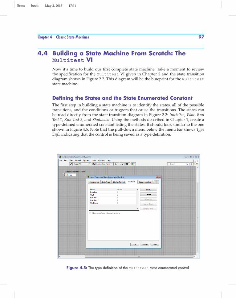
Defining the States and the State Enumerated ConstantThe first step in building a state machine is to identify the states, all of the possibletransitions, and the conditions or triggers that cause the transitions. The states canbe read directly from the state transition diagram in Figure 2.2: Initialize, Wait, RunTest 1, Run Test 2, and Shutdown. Using the methods described in Chapter 1, create atype-defined enumerated constant listing the states. It should look similar to the oneshown in Figure 4.5. Note that the pull-down menu below the menu bar shows TypeDef., indicating that the control is being saved as a type definition.
Figure 4.5: The type definition of the Multitest state enumerated control

Bress book May 2, 2013 17:31
98 Chapter 4 Classic State Machines
Wiring Tip: Always save enumerated state controls as type definitions. Enu-merated state constants will be used many times throughout a given statemachine, and by saving them as type definitions, you help protect your codefrom changes during development. If states need to be added or deleted, youwill only need to change the type definition file, and all of the state constants inthe program will be automatically updated.
Build the Front PanelBuild the front panel of the VI as shown in Figure 2.1. In the programs in this book,this step is trivial since screenshots of the front panels are provided in the functionalspecifications. In real-life projects, this step may require significant design work tobuild a satisfactory and professional user interface.
Lay Out the Skeleton of the State MachineOnce the front panel has been built, lay out the skeleton of the state machine. Placethe main loop, the main case structure, and the guard clause on the block diagram.Make the main loop large enough to fill most of the screen, but leave enough room atthe left and right edges for initialization code and clean-up code. The goal is for theentire state machine to fit on the screen without scrolling.
Style Guide: Always strive to have the state machine fit entirely on one com-puter screen. This makes the code much more readable. If that is not possible,arrange the code so that the user only needs to scroll in one direction: left/rightor up/down.
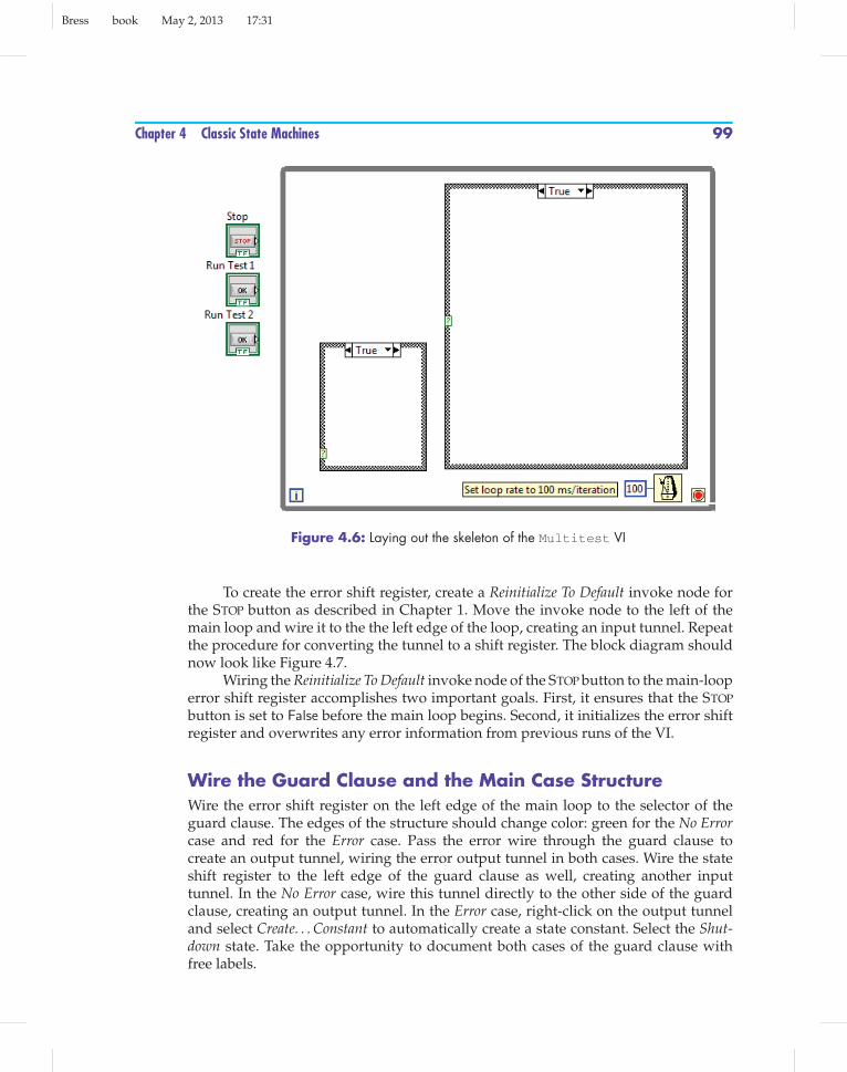
Place the Wait Until Next ms Multiple function in the lower portion ofthe main loop to control the execution timing. Right-click on the millisecond multipleinput and select Create. . . Constant. Set the constant to 100. At this point, the blockdiagram should look something like Figure 4.6.
Create and Initialize the Shift RegistersThe Multitest VI will not need a data highway, so no shift registers are required atthe top of the loop. There will be a shift register for the state constant located in themiddle of the loop, and a shift register for the error cluster located near the bottom ofthe loop.
Drop a copy of the enumerated state control on the block diagram to the left ofthe loop. When controls are dropped directly onto the block diagram instead of thefront panel, they are automatically converted to constants. Wire the state constant tothe left edge of the main loop, creating an input tunnel. Right-click the tunnel, andselect Replace with Shift Register to convert it to a shift register. Set the state constant tothe Initialize state.
Bress book May 2, 2013 17:31
Chapter 4 Classic State Machines 99
Figure 4.6: Laying out the skeleton of the Multitest VI
To create the error shift register, create a Reinitialize To Default invoke node forthe STOP button as described in Chapter 1. Move the invoke node to the left of themain loop and wire it to the the left edge of the loop, creating an input tunnel. Repeatthe procedure for converting the tunnel to a shift register. The block diagram shouldnow look like Figure 4.7.
Wiring the Reinitialize To Default invoke node of the STOP button to the main-looperror shift register accomplishes two important goals. First, it ensures that the STOPbutton is set to False before the main loop begins. Second, it initializes the error shiftregister and overwrites any error information from previous runs of the VI.
Wire the Guard Clause and the Main Case StructureWire the error shift register on the left edge of the main loop to the selector of theguard clause. The edges of the structure should change color: green for the No Errorcase and red for the Error case. Pass the error wire through the guard clause tocreate an output tunnel, wiring the error output tunnel in both cases. Wire the stateshift register to the left edge of the guard clause as well, creating another inputtunnel. In the No Error case, wire this tunnel directly to the other side of the guardclause, creating an output tunnel. In the Error case, right-click on the output tunneland select Create. . . Constant to automatically create a state constant. Select the Shut-down state. Take the opportunity to document both cases of the guard clause withfree labels.

Bress book May 2, 2013 17:31
100 Chapter 4 Classic State Machines
Figure 4.7: Creating and initializing the shift registers for the Multitest VI
Style Guide: It is good LabVIEW practice to use a free label in each case ofevery case structure in a VI.
Now run the state wire from the output of the guard clause to the selector of themain case structure. Right-click on the case menu at the top of the case structure andselect Add Case for Every Value. This will automatically create a case for every state inthe enumerated constant.
The Multitest VI will be polling the STOP, RUN TEST 1, and RUN TEST 2 buttonsin the Wait state, so place them there for now.
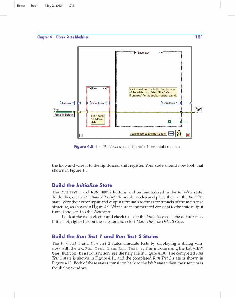
Build the Shutdown StateSelect the Shutdown state and drop a Boolean True constant in the lower-right corner.Wire the constant to the conditional terminal of the main loop. Right-click on theBoolean output tunnel of the case structure and select Use Default if Unwired. This willcause the other states to send a Boolean False (the default value of a Boolean) to theloop conditional terminal.
Drop another state constant in the Shutdown state and set it to Shutdown. Wire itto the edge of the case structure, creating an output tunnel. Then wire the tunnel tothe state shift register.
Wire the error line across the main case structure to the output tunnel and thento the right-hand shift register. Drop a General Error Handler function outside
Bress book May 2, 2013 17:31
Chapter 4 Classic State Machines 101
Figure 4.8: The Shutdown state of the Multitest state machine
the loop and wire it to the right-hand shift register. Your code should now look thatshown in Figure 4.8.
Build the Initialize StateThe RUN TEST 1 and RUN TEST 2 buttons will be reinitialized in the Initialize state.To do this, create Reinitialize To Default invoke nodes and place them in the Initializestate. Wire their error input and output terminals to the error tunnels of the main casestructure, as shown in Figure 4.9. Wire a state enumerated constant to the state outputtunnel and set it to the Wait state.
Look at the case selector and check to see if the Initialize case is the default case.If it is not, right-click on the selector and select Make This The Default Case.
Build the Run Test 1 and Run Test 2 StatesThe Run Test 1 and Run Test 2 states simulate tests by displaying a dialog win-dow with the text Run Test 1 and Run Test 2. This is done using the LabVIEWOne Button Dialog function (see the help file in Figure 4.10). The completed RunTest 1 state is shown in Figure 4.11, and the completed Run Test 2 state is shown inFigure 4.12. Both of these states transition back to the Wait state when the user closesthe dialog window.

Bress book May 2, 2013 17:31
102 Chapter 4 Classic State Machines
Figure 4.9: The Initialize state of the Multitest state machine
Figure 4.10: Help file for the One Button Dialog function
Build the Wait StateThe Wait state is the most awkward and complicated state in the Multitest VI. Thefunction of the Wait state is a demanding one: It must poll all front panel objects andperform whatever calculations are necessary to determined the next state transition.

Bress book May 2, 2013 17:31
Chapter 4 Classic State Machines 103
Figure 4.11: The Run Test 1 state of the Multitest state machine, where the test is simulated bya one-button dialog and after the completion of the test the state machine returns to the Wait state
Figure 4.12: The Run Test 2 state of the Multitest state machine, where the test is simulated bya one-button dialog and after the completion of the test the state machine returns to the Wait state

Bress book May 2, 2013 17:31
104 Chapter 4 Classic State Machines
The Multitest VI has relatively few front panel objects, so this task isn’t very dif-ficult. But as the number of front panel objects increases, polling all of the objectsbecomes more unmanageable. Fortunately, LabVIEW provides event structures toperform this task cleanly and easily. This topic will be addressed in Chapter 10.
In the MultitestVI, the front panel objects are all Booleans. This makes moni-toring the front panel easier, since Booleans only have two values: True and False. Oneway to monitor a set of Boolean controls is to use a conditional ladder. A conditionalladder is a series of conditional statements that tests each control in turn. A conditionalladder would read something like “If STOP was pressed choose the Shutdown state,else if the RUN TEST 1 button was pressed choose the Run Test 1 state, else if the RUNTEST 2 button was pressed choose the Run Test 2 state, else go back to the Wait state.”
A conditional ladder can be implemented in LabVIEW using the Selectfunction with the help file shown in Figure 4.13. The Select function accepts threeinputs: a Boolean selector input, a True input, and a False input. The data types of theTrue input and the False input must match. If the Boolean selector input is True, theSelect function passes the value of the True input. If the Boolean selector input isFalse, the Select function passes the value of the False input. The Select functionis demonstrated in Figure 4.14. This VI outputs x if x ≥ y and outputs y otherwise.
Select functions can be connected in a cascade to form a conditional ladder, asshown in Figure 4.15. By following the dataflow, you can confirm that this cascade ofSelect VIs behaves in the same way as the conditional ladder described previously.
Figure 4.13: Help file for the Select function

Bress book May 2, 2013 17:31
Chapter 4 Classic State Machines 105
Figure 4.14: Using the Select function
Figure 4.15: The Wait state of the Multitest state machine, where the Wait state uses aselector ladder to poll the front panel controls and to decide which state to go to next
If the STOP button is True, the topSelectpasses the Shutdown state to the shift register.If the STOP button is False, the result of the middle Select is passed on. The middleSelect checks the status of the RUN TEST 1 button. If it has been pressed, the RunTest 1 state is passed on to the shift register. The bottom Select function passes onthe Run Test 2 state if the RUN TEST 2 button has been pressed. Finally, the bottomSelect passes on the Wait state if none of the buttons have been pressed.
This method is effective, but it becomes awkward for large number of Booleancontrols and even more awkward if non-Boolean controls need to be monitored.Another drawback is that all of the front panel objects need to be polled every loopiteration. This is not an efficient use of computer resources.


