ADVANCED BINARY GEOTHERMAL POWER...
46
€GG-€P--9207 DE91 010065 ADVANCED BINARY GEOTHERMAL POWER PLANTS LIMITS OF PERFORMANCE C. J. Bliem G. L. Mines Pub1 i shed January 1991 EG&G Idaho, Inc. f Idaho Falls, Idaho 83415 PreDared for the U. S. Department of Energy Idaho Operations Office Under DOE Contract No. DE-AC07-76ID01570 W ’ DiSTh3UTION OF THIS DOCUMENT IS UNLIMITE?
Transcript of ADVANCED BINARY GEOTHERMAL POWER...
€GG-€P--9207
DE91 010065
ADVANCED BINARY GEOTHERMAL POWER PLANTS L I M I T S OF PERFORMANCE
C . J. Bliem G . L. Mines
Pub1 i shed January 1991
EG&G Idaho, Inc. f Idaho Falls, Idaho 83415
PreDared for the U . S . Department of Energy
Idaho Operations Office Under DOE Contract No. DE-AC07-76ID01570
W ’ DiSTh3UTION OF THIS DOCUMENT IS UNLIMITE?

DISCLAIMER
This report was prepared as an account of work sponsored by an agency of the United States Government. Neither the United States Government nor any agency Thereof, nor any of their employees, makes any warranty, express or implied, or assumes any legal liability or responsibility for the accuracy, completeness, or usefulness of any information, apparatus, product, or process disclosed, or represents that its use would not infringe privately owned rights. Reference herein to any specific commercial product, process, or service by trade name, trademark, manufacturer, or otherwise does not necessarily constitute or imply its endorsement, recommendation, or favoring by the United States Government or any agency thereof. The views and opinions of authors expressed herein do not necessarily state or reflect those of the United States Government or any agency thereof.

DISCLAIMER Portions of this document may be illegible in electronic image products. Images are produced from the best available original document.
ACKNOWLEDGEMENTS
The work i n t h i s repor t was undertaken t o answer a question put t o one o f the authors by Raymond LaSala o f the Department o f Energy's Geothermal Division. Ray asked how closely an actual binary geothermal system could approach the thermodynamic maximum conversion o f the thermal energy i n the geofluid t o work, fee l ing tha t 75% might leave s ign i f i can t room f o r improvement. One o f the authors (CJB) could not answer the question re la ted t o the magnitude o f the i r r e v e r s i b i l i t i e s associated wi th the necessary t ransfer o f heat (pinch points o r l o g mean temperature dif ferences) and conversion t o work i n ro ta t ing machinery ( isentropic ef f ic ienc ies) . This repor t i s the resu l t o f our th inking on t h i s subject. Thanks, Ray.
I
The repor t has been reviewed by several people i n the indus t r ia l sector f o r t h e i r perspective. We acknowledge the e f f o r t o f Richard Campbell o f the Ben Ho l t Company, Michael Forsha o f Barber Nichols Engineering, and Joel Rosenbl a t t and Stanley Saulson o f Polythermal Technologies Corporation f o r t h e i r review o f the i n i t i a l report. I n addition, we thank the people a t Exergy Inc. who generated the numbers f o r comparable cases f o r t h e i r System 12 t o the performance o f the other systems.
who gave us the "Rule-of-Thumb" tha t economic optimization occurred a t second law e f f i c ienc ies i n the neighborhood o f 70 t o 75% f o r systems o f the type being considered here.
Energy and the indus t r ia l sector. The conclusions, however, are those o f the authors alone.
Most o f a1 1 the authors acknowledge Dr. Alexander Kal ina o f Exergy Inc.
We are great fu l f o r a l l o f the assistance received f rom the Department o f
iii


ABSTRACT
The Heat Cycle Research Program is investigating potential improvements to power cycles uti1 izing moderate temperature geothermal resources to produce electr'ical power. binary power systems. Bihary Rankine cycles are more efficient than the flash steam cycles at moderate resource temperatures, achieving a higher net brine
plant, it has been shown that mixtures of saturated hydrocarbons (alkanes) or ha1 ogenated hydrocarbons operating in a supercri tical Rankine cycl e gave improved performance over Rankine cycles with the pure working fluids executing single or dual boiling cycles or supercritical cycles.
Investigations have specifically examined Rankine cycle
'effectiveness. At resource conditions similar to those at the Heber binary
Recently, in addition to the supercritical Rankine Cycle, other types of cycles have been proposed for binary geothermal. service. This report explores the feasible limits on efficiency of a plant given practical limits on equipment performance and discusses the methods used n these advanced concept plants to achieve the maximum possible efficiency. (Here feasible is intended to mean reasonably achievable and not cost-effective. No direct economic analysis has been made because of the sensitivity o economic results to site specific input. The intent here is to take a gener iook at systems which will probably be cost effective when used in sp applications. The .
results are expected to be close to. the economi asible points.) The 1 imit of performance o f three advanced plants were considered in this report. The performance predictions' were ta The advanced plants considered appe performance. Ultimately, the plant disadvantages of the different cycl service.
In addition to'the results des report presents a standard o f comp the Heat Cycle Research Program and in the indust or by Exergy, Inc. and Polythermal Technologies. The report can be ered a "Report*Card" of sorts indicating how far we have come and how much further it is feasible to go in performance of these energy conversion systems.
V

i
CONTENTS
INTRODUCTION .......................................................... 1
CYCLE PERFORMANCE LIMITATION .......................................... 4
Background ........................................................... 4
Results ................. ........................................... 6
ADVANCED SYSTEM PERFORMANCE ........................................... 18
Systems With Outlet Temperature Constraints .......................... 18 Systems Without Out1 et Temperature Constraints ...................... 26
CONCLUSIONS ........................................................... 32
REFERENCES ............................................................ 36
Methodology .......................................................... 6
FIGURES
Figure 1 . Figure 2 . Figure 3 .
Figure 4 . Figure 5 .
"Unobtainium" cycle with unconstrained outlet temperature ........................................ 7
Efficiency of "unobtainium" cycle with unconstrained outlet temperature .......................... 9
"Unobtainium" cycle with constrained
Efficiency of "unobtainium" cycle with
Recuperated rankine cycle ................................. 14
outlet temperature ........................................ 12
constrained outlet temperature ............................ 13
Figure 6 . Recuperated "unobtainium" cycle with
Figure 7 . Efficiency of recuperated "unobtainium" cycle with constrained outlet temperature ................. 17
Figure 8 . Temperature-enthalpy diagram for
Figure 9 . Kalina system 12 .......................................... 21
Figure 10 . Temperature-enthal py diagram for kalina system 12 ...................................... 22
Figure 11 . Comparison between kalina system 12
Constrained Outlet Temperature ............................ 15
supercritical rankine cycle ............................... 19
and a supercritical rankine cycle ......................... 24
i
vi i

Figure 12 . Comparison between two cycles ............................. 26
Figure 13 . The trilateral cycle ...................................... 28
Figure 14 . Supercritical rankine with expansion "through- t he-vapor-dome" .................................. 29
Figure 15 . Temperature-enthalpy diagram comparing cycles with no minimum outlet temperature limits ................. 30
Figure 16 . Comparison between cycles with no minimum temperature 1 imit .............................. 31
Figure 17 . Results for advanced systems .............................. 34
Table 1 . Silica deposition limits ................................... 12
v i i i

POWER PLANTS NCE
I HTRODUCTI ON
The Heat Cycle Research Program .is currently investigating potential improvements to power cycles. util izing moderate-temperature geothermal resources to produce electrical power. The technology being considered either improves the performance of the power cycle thus reducing the cost of electricity, or it provides a means of utilizing a resource which might otherwise not be used because of institutional or technical barriers. Although geothermal energy is provided by nature, it is generally expensive to produce, and compared to fossil fuel, is a low grade energy source. Because of the low quality and high cost of the energy, optimized systems for the generation of electrical power should utilize as much of the energy contained in a unit mass of .the fluid as possible. This optimization was confirmed with both a "value analyses" study and a "market penetration" study which examined the impact of performance improvements on the cost of electricity and on the ,future util ization of geothermal produced electrical power if these improvements could be realized le2. The net brine effectiveness, .or, the net electrlcal energy produced by the plant per unit mass of geofluid, has been used by this program as a primary indicator of the improvements in the cy
In previous work in the Heat Cycle Research
performance
i ncl uded the paras i ti c power resul ti ng rom heat rejection, but did not include the parasi tic power requi red to produce and inject the geofluid. The rationale for this was that the geofluid power requirements were site specific and no generic approximation was valid. Today, with many different types of heat rejection systems, the same could be said for the heat rejection parasitic. There are many different types of heat rejection used in di erent environments in geothermal applications today from total dry cooling to et cooling with convent1 ona1 cool i ng towers. rejection parasitic should be considered as a separate issue in the same manner as is used for the geofluid production parasitic. Therefore, in this report, the net plant power does not include-the heat rejection parasitic.
It is believed that in order to make the results more meaningful, the heat
In addition, the results

i n t h i s repor t are given i n terms o f a second law e f f i c iency instead o f a geof lu id effectiveness. The geof lu id effectiveness can be obtained by mu1 t i p l y i n g the second law e f f i c iency by the avai lable energy i n the geof lu id (per u n i t mass o f geofluid). The use of the ef f ic iency gives a parameter which i s r e l a t i v e l y independent o f resource temperature, while the maximum geof lu id effectiveness (the avai lable energy i n the geofluid) i s a strong function o f resource temperature.
The Heat Cycle Research Program investigations have spec i f i ca l l y examined binary power cycles because f o r the moderate temperature resources o f interest , the binary cycles are more e f f i c i e n t than the f lash steam cycles, achieving a higher net br ine effectiveness. such as supercri t i c a l heating, in tegra l countercurrent condensation, appropriate choice o f working f l u id , and metastable turbine expansions were explored. A t resource conditions s imi la r t o those a t the Heber binary plant, Demuth 3*4 and Demuth and Kochan found tha t mixtures o f saturated hydrocarbons (alkanes) with these advanced concepts gave a 29% performance improvement over the Heber plant; B l i e m mixtures (Freons) were used.
I n these investigations o f the binary power cycle, advanced concepts
i n subsequent studies showed tha t the same resu l ts were t rue i f halocarbon-
With the projected improvements i n performance from the concepts i d e n t i f i e d i n these analy t ica l studies, the program has i n i t i a t e d f i e l d invest igat ions t o fur ther examine the potent ia l performance gains wi th these concepts '*'. The f i e l d invest igat ions o f the concepts are being conducted a t the Heat Cycle Research F a c i l i t y current ly located a t East Mesa i n Cal i fornia 's Imperial Valley. These f i e l d studies examine the v a l i d i t y o f the predicted performance improvements through the v e r i f i c a t i o n o f the assumptions used i n the predictions, and the adequacy o f the "state-of-the-techno1 ogy" design methods, i ncl udi ng f l u i d transport properties. Methods t o insure tha t assumed conditions such as in tegra l , countercurrent phase change have been achieved.
Recently, a number o f new concepts f o r power cycles f o r geothermal use have been introduced and published performance data f o r these systems i s available. For t h i s paper, the operating conditions f o r the supercr i t ica l Rankine cycle have been adjusted f o r d i rec t comparison wi th the other systems. Inc. introduced the Kalina System 12 for geothermal use '. Polythermal Technologies Corporation i s considering t h e i r Low-Temperature Engine System f o r power production
I n January o f 1989, Exergy
2

from a flashing well lo. This system employs a heat-driven heat pump and two separate heat engine cycles. One engine's heat input is from the heat rejected by the other engine and this engine reJects heat to the heat pump at a temperature lower than atmospheric which is pumped to atmospheric by the heat pump. In the United Kingdom, the Trilateral Wet Expansion System is being proposed for a binary application with a hot-dry rock resource ll. These new concepts rely on similar considerations to those studied in the,Heat Cycle Research Facility (HCRF). One of the primary prerequisites for the achievement of the predicted performance of each of these systems which utilize mixtures of hydrocarbons as working fluids i s that phase changes (boiling and condensation) be carried out close to equilibrium with the phases mixed. This has been studied in the HCRF in detail for the condensation process. In the HCRF investigati the generation of vapor without the problems assoc mixture.
the use of supercritical vaporization allows d with boiling a two-component
For all such cycles, there is a sink temperatures, and practical as efficiencies and heat exchanger app temperature differences (LMTD's) . reviews the performance of
rmance limit for a given resource and o rotating equipment
ture 'differences or 1 og mean xamines this performance limit and
me of the advanced systems.
The Heat Cycle Research program is being conducted by the Idaho National Engineering Laboratory. The work is supported by the U.S. Department of Energy, Assistant Secreta
manager and Mr. K. J. Office .
and Renewable Energy, und DE-AC07 - 76 I DO1 570 othermal Division is th
through the Idaho Operations
CYCLE PERFORMANCE LIMITATION
Background
A second-law-of-thermodynamics analysis is useful in determining the 1 imitations of performance of power generation systems. Briefly, the second law allows for the definition of available energy, defined by Obert 12:
"Available energy i s that portion of energy which could be converted into work by ideal processes which reduce the system t o a dead state--a state i n equilibrium with the earth and i t s atmosphere."
If a system is at a different pressure from the atmosphere, work can be obtained by
surroundings, work may be obtained by transferring heat to a work producing ansion to atmospheric pressure. If a system is at a different temperature than
cycle (heat engine). substance is a hydrocarbon, a reactio hich oxidizes the hydrogen to water and .the carbon to carbon dioxide or carbonate has the potential to produce w report, chemical reaction will not be considered.) Available energy is essentially the same as availability, exergy and essergy.
If chemical reactions are possible, for example, if the
The available energy, A, of a stream in steady flow is:
A = m [(h - ho) - To (s - so)] (1)
where m is the mass flow rate; h, enthalpy; T, absolute temperature; and s, entropy. The subscript o represents the value at the pressure and temperature of the environment, the dead state.
The irreversibility of a process or physical component, I, is the sum of all of the increases and decreases in available energy occurring and can be shown to be equal to:
I = - To B m, Dsn
where To is the absolute ambient temperature; mn, the mass flow rate of the nth stream; and Ds, the change in entropy for the nth stream. Kalina l3 has shown that
4

if the cooling water is assumed to be the sink instead of the ambient temperature or ambient wet bulb temperature, an effective ambient temperature can be defined as:
To = T, (2 - [ 1 n (',/'e 1 / (Ti 1 1 1 (3)
where Ti and Te are the inlet and outlet temperatures of the coolant sink in absolute units. For temperatures encountered in normal power production, To can be approximated within hundredths of a percent by:
' 0 (Ti + Te)/2 (4)
j .e. , the mean cool ant temperature.
Note that, for a process, the outlet available energy is the inlet available energy plus the irreversibility. For example, for a process transferring heat from a stream at T, to a stream at T, in steady flow, the irreversibility will be:
dI/dq = (To DT)/(T, T,) (5)
where all o f the temperatures are in absolute units and DT is the temperature difference across which the heat is transferred, that is T,-T,. An important observation i s that if T, and>T, are significantly greater than To, the irreversibility per unit heat transfer at fixed DT is significantly lower than if they are at temperatures near To. If T, and T, are about 1.5 times To (typical of the heat addition process) the irreversibility per unit heat transferred at a fixed To and DT will be 44% that of a heat transfer process .in which T, and T, are approximately equal to To such as the heat rejection process. This implies that closer approaches are advantageous (increase efficiency more) in the heat rejection process than in the heat addition process.
raphically 'shows this relationship' by plotting an "exergetic Te,, instead of actual .temperature on heat duty plots .for heat
exchange, where:
T,, 1 - (TJJ). (6)
5

Then, 4
dI/dq = D Tex (7)
where D Tex is the difference in the hot and cold exergetic temperatures. more complete discussion see a basic engineering thermodynamics text (see Reference l2 1.
For a
Methodology
A realistic maximum can be placed on the work produced for a given resource using the ideas discussed in the previous section. for heat exchanger pinch-point temperature differences or log-mean temperature differences (LMTD's) and for rotating machinery isentropic efficiencies, the irreversibilities associated with the heat transfer and work processes in a cycle with the optimum match between working fluid and heat source and heat sink can be calculated. The work produced by a given cycle can be determined by subtracting from the available energy in the geofluid source, the irreversibility associated with each of the cycle devices: the heater, the turbine, the condenser (heat rejection) and the pump.
If one assumes logical values
This analysis attempts to be generic in its application. The efficiency produced by this analysis is for the plant only. power associated with the heat rejection system, or the geothermal supply and injection system. These systems are separate and the impact of each may vary considerably depending on the particular application. The plant i s a separate unit and can be considered separately. The choice of the type of heat rejection system and impact of the supply and injection system are left for a site-specific analysis.
Results
It does not include parasitic
Restricting the analysis to liquid resources, a working fluid i s postulated which will give close to the minimum irreversibility in each component with a real istic temperature difference in heat exchangers and real istic isentropic efficiency for turbines and pumps. Figure 1 shows the heat addition and heat rejection curves for the ideal working fluid, "unobtainium". For a given pinch
6

I I
7
point temperature difference, the minimum heat exchanger irreversibility occurs with a nearly constant temperature difference. With a fixed log-mean temperature difference (LMTD) for the exchanger, the appropriate average temperature difference for calculating the heat transfer in a heat exchanger with a varying temperature difference, the minimum irreversibility occurs with a slightly smaller temperature difference on the end of the heat exchanger nearer to To. For heater temperatures in the range of this study, for an LMTD of 10°F, a temperature difference on the cold side of the exchanger of 8 to 9 O F (on the hot side, 11 to 12.1OF) gives slightly lower heater irreversibility than a uniform 10°F difference. That increase is between 0.6 and 1.2% of the heater irreversibility, and is thought to be not worth considering in order to simplify the problem to one of a uniform temperature difference. All enthalpies are referenced to the geofluid mass. Note that the difference between the heat added in the heater and that rejected in the condenser is the cycle net work per unit mass of geofluid.
It is further assumed that an "unobtainium" turbine will have an efficiency of 85% and that the pumping work for the "unobtainium" will be negligible when compared to the turbine work. With the approximation that the second law turbine efficiency is approximately equal to the isentropic efficiency, the net work is approximated by applying the turbine efficiency to the available energy in the geofluid minus the irreversibilities in the heat transfer processes.
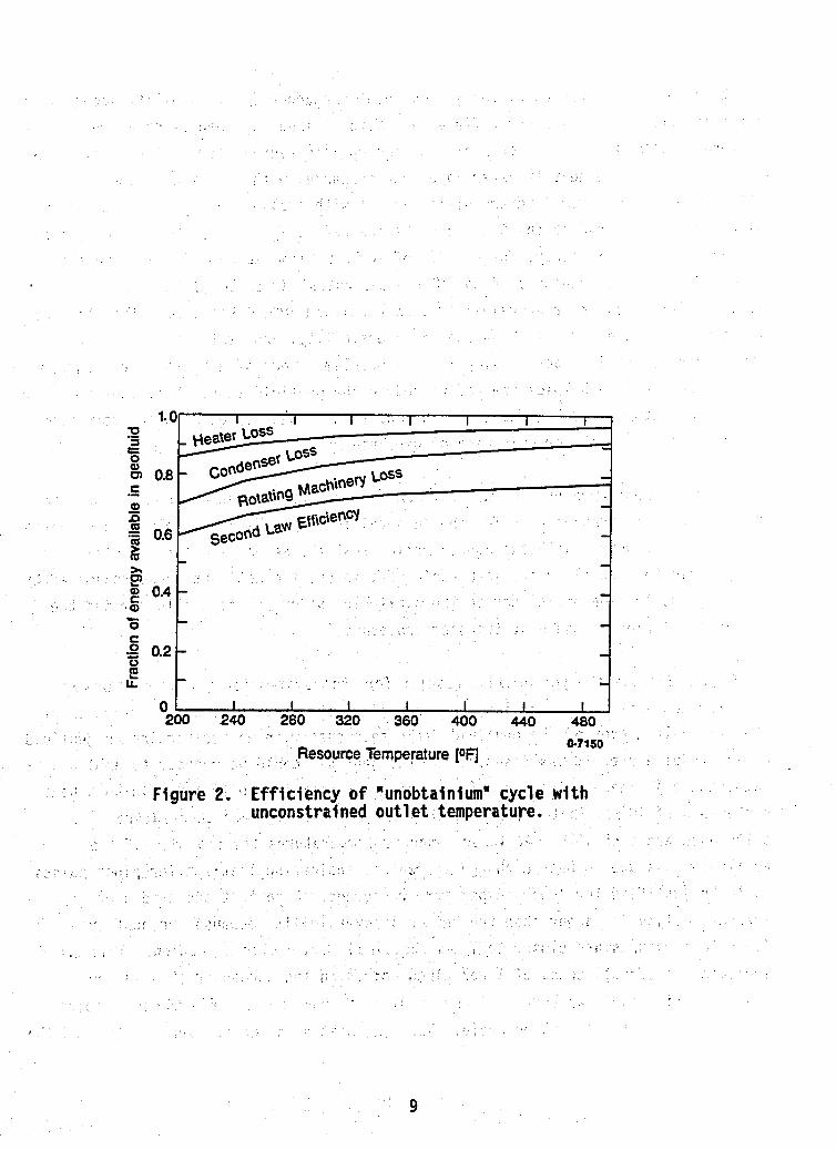
Figure 2 shows the performance results for this system for different maximum resource temperatures. Each loss or irreversibility is expressed as a fraction of the available energy of the geofluid. outlet temperature, it was assumed that the geofluid could be reduced to ambient temperature.) These results are for a uniform temperature difference in both heat exchangers of 10°F. That is, the pinch point and the log mean temperature difference are each 10OF. At lower resource temperatures the fraction of the available loss due to heat exchange increases, indicating that smaller pinch points would be justified for lower temperature resources. Note that the condenser irreversi bi 1 i ty is 1 arger than the heater i rreversi bi 1 i ty because the heat exchange fluid temperatures are closer to To as explained in a previous section. This would indicate the effectiveness of lower pinch points in the condenser than in the heater. This point has been explored by Bliem l4 from a cost-effectiveness point
(In this case with no restriction on geofluid
8
9

point temperature difference, the minimum heat exchanger irreversibility occurs with a nearly constant temperature difference. With a fixed log-mean temperature difference (LMTD) for the exchanger, the appropriate average temperature difference for calculating the heat transfer in a heat exchanger with a varying temperature difference, the minimum irreversibility occurs with a slightly smaller temperature difference on the end of the heat exchanger nearer to To. For heater temperatures in the range of this study, for an LMTD of 10°F, a temperature difference on the cold side of the exchanger of 8 to 9'F (on the hot side, 11 to 12.loF) gives slightly lower heater irreversibility than a uniform 10°F difference. That increase is between 0.6 and 1.2% of the heater irreversibility, and is thought to be not worth considering in order to simplify the problem to one of a uniform temperature difference. All enthalpies are referenced to the geofluid mass. Note that the difference between the heat added in the heater and that rejected in the condenser is the cycle net work per unit mass of geofluid.
It is further assumed that an "unobtainium" turbine will have an efficiency of 85% and that the pumping work for the "unobtainium" will be negligible when compared to the turbine work. With the approximation that the second law turbine efficiency is approximately equal to the isentropic efficiency, the net work is approximated by applying the turbine efficiency to the available energy in the geofluid minus the irreversibil ities in the heat transfer processes.
Figure 2 shows the performance results for this system for different maximum resource temperatures. Each loss or irreversibility is expressed as a fraction of the available energy of the geofluid. outlet temperature, it was assumed that the geofluid could be reduced to ambient temperature.) These results are for a uniform temperature difference in both heat exchangers of 10'F. That is, the pinch point and the log mean temperature difference are each 10'F. At lower resource temperatures the fraction of the available loss due to heat exchange increases, indicating that smaller pinch points would be justified for lower temperature resources. Note that the condenser irreversibility is larger than the heater irreversibility because the heat exchange fluid temperatures are closer to To as explained in a previous section. This would indicate the effectiveness of lower pinch points in the condenser than in the heater. This point has been explored by Bliem l4 from a cost-effectiveness point for the supercritical Rankine cycle. When the heat exchange irreversibility and the
(In this case with no restriction on geofluid
10

rotating machinery irreversibility fractions are subtracted from unity, the second law efficiency (net plant work divided by the available energy in the geofluid) remains. For this system, the efficiency varies from about 65 to 75% depending on the resource temperature, for this LMTD and rotating machinery efficiency.
In many cases, the minimum temperature to which the geofluid can be cooled is 1 imited by concerns over deposition of silica. Calculations for the concentration of silica based on the solubility of quartz in water at the resource temperature and the temperature of precipitation of amorphous silica at this concentration, give an estimate of the temperature at which silica deposition will occur. 15.) Actually, there are many other variables including concentration of other components in the solution, but this give an approximate value which can be used in a generic analysis. Table -1 'indicates- th this calculation. The minimum geofluid outlet temperature .increases as the resource temperature increases and is less than the ambient temperat
(See Reference
-To at resource temperatures bel ow 280'F.
Figures 3 and 4 depic this case with -a single heater and single condenser. is impossible to maintai constant temperature differences in both the heater and condenser as was done in the previous case. It was decided to minimize irreversibilities in the condenser rather than in the heater by maintaining a constant temperature difference in the condenser. in the heater is not uniform. The temperatu difference on the hot end of the heater is changed to obtain LMTD's leaving the condenser had been rai nser irreversibility would have been more than the decrease in the heater irreversibility. This would have resulted in a net increase in cycle irreversibility. The net plant second law efficiency with this restriction was between 55 and 60%. The heater irreversibility is increased over the case with no limit in outlet temperature. The shapes of the curves in Figure 4 (discontinuous slopes) result from the fact that there is no outlet temperature limit below 280°F and the limit temperature increases as the resource temperature increases. (Below that temperature, 28OoF, the curves are identical to Figure 2.)
It
.~
hen the temperature difference
"unobtainium" temperature
In the case of a restricted minimum geofluid temperature, adding internal recuperation allows the heater irreversibility to be decreased substantially (although there is an added irreversibility associated with the recuperative heat
11

Table 1.. Silica deposition limits
Resource
Temperature
200
250
300
350
400
450
500
I Si1 ica
Depos i ti on 11 Temperature I
I 103.07
149.35 11 197.23
246.78
298.09 1

!
_ _ ~ ~ _ _ ~ ~ ~
0.7134 Enthalpy Per Unit Mass of Geofiuid
13

I
1.01 I 1 I I 1 I I 1
0.4
C
0
LL
,o 0.2 E
O l I I I I I I 200 240 280 320 360 400 440 480
Resource Temperature [OF] 0-7148
Figure 4. Efficiency of "unobtainium" cycle with constrained out1 et temperature.
14
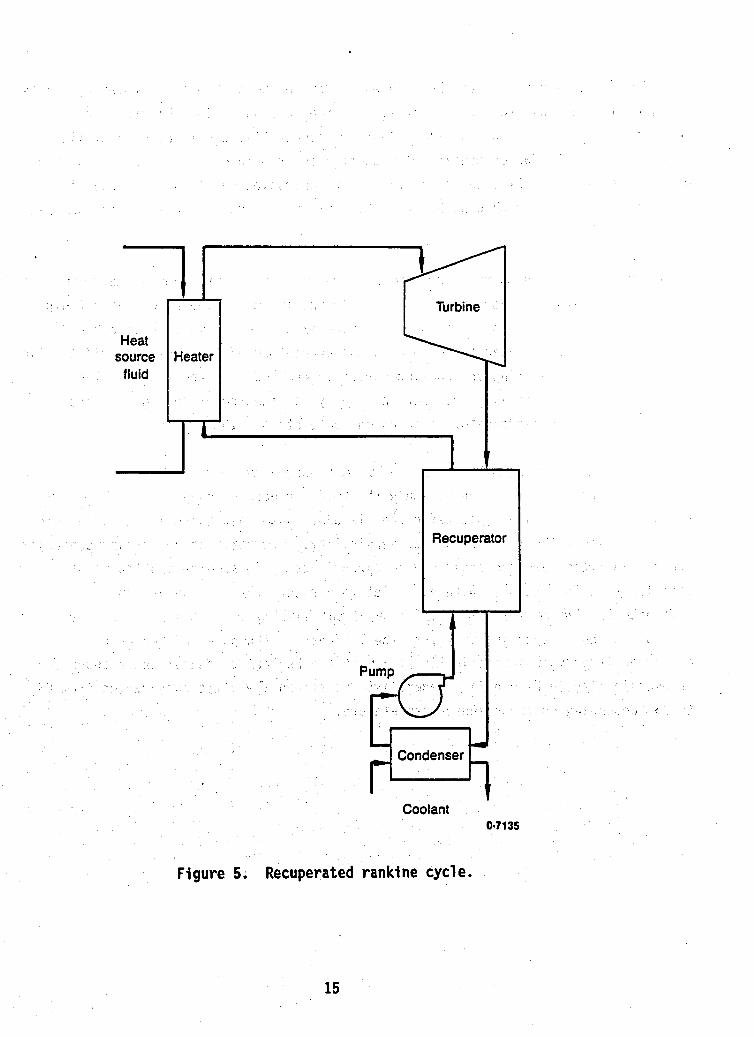
Figure 5.
Recuperator
Coolant 0.71 35
Recuperated ranki ne cycle.
15
transfer.) These results have been shown by Demuth and Kochan using turbine exhaust to recuperatively heat the working fluid. schematic diagram of such a system. Another recuperative scheme used in utility steam plants is feedwater heating with steam bled from intermediate turbine stages. Demuth and Kochan considered this method of recuperation but found, in general, results were no better than with the turbine exhaust recuperation which is somewhat 1 ess compl ex.
for a Rankine cycle Figure 5 shows a
Figure 6 shows the temperature enthalpy (heat duty) diagram for an "unobtainium" cycle with internal recuperation. The hot "unobtainium" in the recuperator would come from the expansion process as hot turbine exhaust or a small turbine bleed stream. This heat is used to perform enough preheating of the working fluid to give an ideal match of heating and cooling curves in the heater. The match in the recuperator may not be as good. For this analysis, the temperature difference at the hot end of the recuperator is adjusted to maintain a 10°F LMTD.
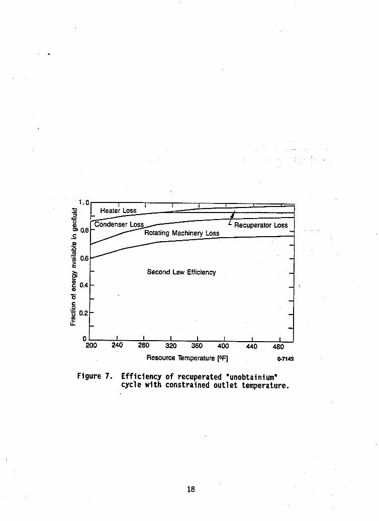
Figure 7 shows the performance results for the recuperated cycle with a geofluid outlet temperature limit. Here, again the LMTD for each exchanger is 10°F and the rotating machinery isentropic efficiency is 85%. Note that there is an added loss for this system, the recuperator irreversibility. However, the heater and condenser irreversibil ities are decreased giving approximately the same second law plant efficiency as for the case with no outlet temperature restriction as found in Reference 5. The recuperator takes some of the heating duty from the heater and some of the heat rejection duty from the condenser. condenser irreversi bil i ties in Figure 2 with the heater, condenser and recuperator irreversibility in Figure 7). Generally, the second law efficiency varies from 65 to 75% depending on the resource temperature.
(Compare the heater and
16

- Recuper. ator
"Unobtainium
Heater 1 1
- Condenser
0.7146 ' Enthalpy Change Per Unit Mass Geofluid
Figure 6. Recuperated "unobtainium" cycle with Constrained Out7 et Temperature.
17
Second Law Efficiency
1.0- I 1 I I I - I
I Recuperator Loss
ting Machinery Loss - - -
Q s - - c 0.4 - 9)
0 - C 0
- - .- 'ii 0.2 - !? u. -
- -
O k I 1 1 1 I I 1
- 1
Figure 7. Efficiency o f recuperated "unobtainium" cycle with constrained outlet temperature.
18

ADVANCED SYSTEM PERFORMANCE
How close do the latest advanced cycles approach the maximum plant efficiency defined in the previous section? It is convenient to separate systems which have a limit on the geofluid outlet temperature from those which do not. In the following section, systems with limited geofluid outlet temperature will be considered. Most of the systems have been optimized for operation under this constraint. The second section considers systems without this constraint, the Trilateral cycle and the Heat Cycle concept of turbine expansion "through-the-dome" l6 are examples of this type of system.
Systems with Outlet Temperature Constraints
Three proposed systems are considered to illustrate the methods which use real fluids to approach the behavior of "unobtainlum." A supercritical Rankine cycle with exhaust gas recuperation and a Kalina System 12 are discussed in some detail and the Polythermal Technologies Low Temperature Energy System is a1 so discussed, but not to the same degree because there is less in the literature concerning specific state-point data, Kalina System 12 are given in Reference 17 where the two systems are compared under the same assumptions. More detail on individual processes in the Kalina System is given in Reference 9 and the supercritical Rankine cycle illustrated here is discussed in earlier work from the Heat Cycle Research program 4*5e6. The results
State points for the supercritical Rankine cycle and the
quoted here are for a liquid resource at 376 O F .
The path pursued in the Heat Cycle program has been to use a Rankine cycle as depicted in Figure 5 and approximate the nearly linear heating curve of working fluid by operating at pressures above the critical point. The use of a mixture allows critical pressures and temperatures to be matched with the given resource maxi mum temperatu for 600 psi flang
Figure 8 show a t cycle. (This rep mperat ure - ent ha1 py because it is more familiar to designers. used, the area between curves would be directly proportional to the heat transfer
ample, below the rating
rocesses of the
If the exergetic temperature had been
19

I-+-- Heaters !cuperators
I coolant
-Condenser ‘-1 Work
Enthalpy Per Unit Mass of Geofluid 0-6778
Figure 8. Temperature-enthalpy diagram for supercritical rankine cycle.
20

irreversibility). temperature difference at the hot end of the heater represents approximately half
In this diagram, as discussed in the background section, a
the irreversibility of the same temperature difference in the condenser because of their relation to To. Note that the largest temperature differences are near the hot and cold ends of the heater. The enthalpy change of the condenser is lined up with the heater because the difference in heat transferred is the net work for the cycle. The temperature difference in the condenser is practically constant. This is a result of using a mixture for $a working fluid and achieving integral condensation in countercurrent flow. The recu by using turbine exhaust has a relatively small heat duty and a nearly constant temperature difference resulting in a small .absolute irreversibility.
ator, which heats the working fluid
The primary inefficiency is the large temperature difference near the cold end of the heater.
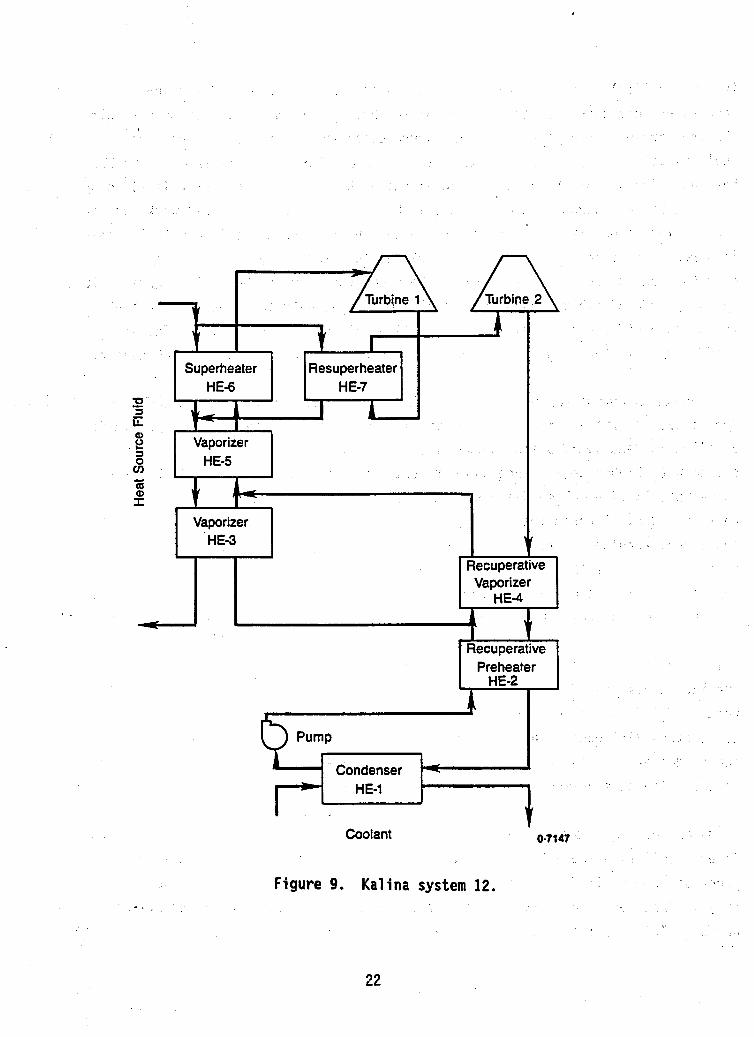
Another advanced system operating under the e constraints is the Kalina System 12. Figure 9 shows a schematic diagram of this system. This system was unveiled in January 1989 and Exergy, Inc. has, since that time, developed a newer system with higher performance and more complexity which might be desirable for a large installation. The Kalina system uses a’mixture of water and ammonia as the working fluid. Because the working fluid becomes wet as it expands, a reheat stage and second turbine are required. Figure 10 shows a temperature-enthalpy diagram for this system. Note that because the superheater and reheater heat the working fluid through a similar temperatur range, irreversibilities are minimized by splitting the geofluid flow between th e ’units. (This is the rightmost part of the figure. Note that the individual heat initial vaporization of the working fluid is split between the geofluid in HE-3 and turbine exhaust in HE-4. (The discontinuity in slope of the heating curve of the working fluid is a result of the split flow) This is necessary to maintain small temperature differences in HE-5 while avoiding a temperature pinch in HE-3. Again the condenser is lined up with the external heater train and the net work is shown as the difference between the heat transfer in and out.
I
changers are identified on both figures). The
Comparing Figures 8 and 10 show that there is little difference in heat exchange irreversibility between the two systems. Temperature differences in the heating processes are similar for the two systems duty is done recuperatively, to avoid temperature pinch at the cold end of the heater. This results in a larger irreversibility in the System 12.
In thebsystern 12, more of the heating
It is
21
I Superheater Resuperheater
HE-6 H E-7 P *
1 A, G A a =I 0 v)
m
- 2 Vaporizer
HE-5 ;
w
P Vaporizer
H E-3 V Recuperative Vaporizer
HE-4 - ' Recuperative
Preheater H E-2
Condenser -4
HE-1 L
Coolant 0-1141
Figure 9. Kalina system 12. ..
22

i
1 Rnriinarstnr ' Uastarc
' //
' I / / I '
- Work i perature-enthalpy diagram kalina system 12.
23
interesting to note that per unit of work produced approximately 25% more heat is transferred in the System 12 than in the supercritical Rankine system.
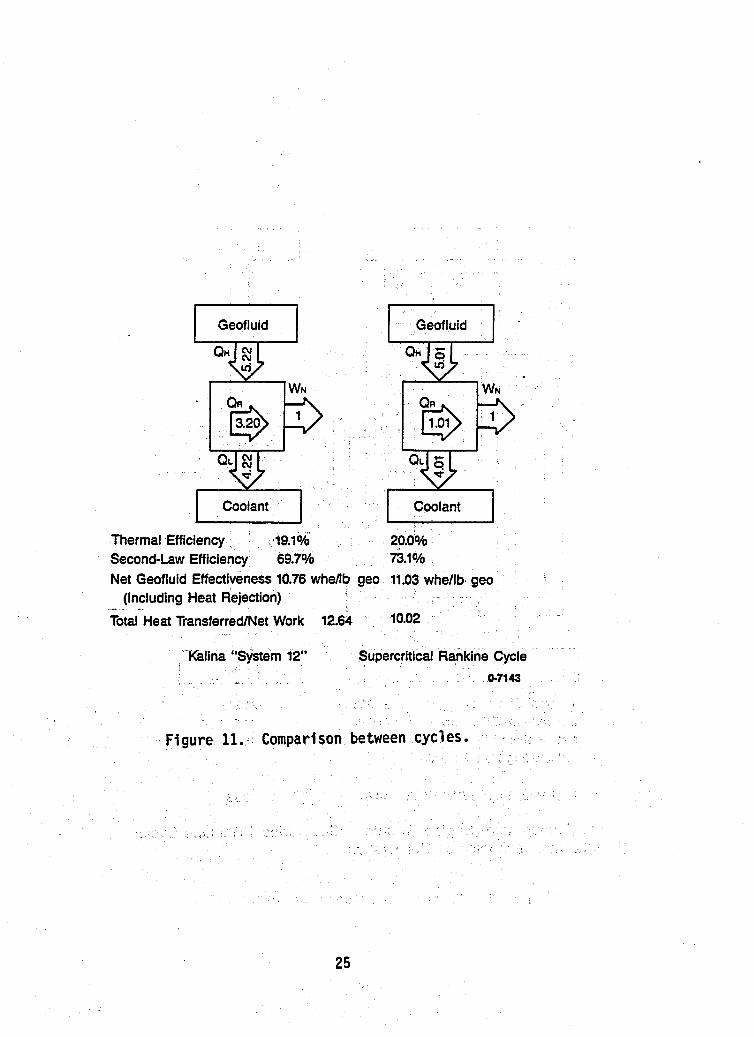
Figure 11 shows a comparison between the supercritical Rankine cycle and the Kalina System 12. work. Note that the Kalina system 12 requires three times the amount of recuperative heat transfer (0,) and for the entire cycle approximately 26% more heat is transferred per unit of work produced. The heat load on the plant will be 26% greater for the same size plant. Since, the overall heat transfer coefficients for the two plants will be different the heat exchanger sizes will depend on more than heat load. When heat rejection parasitic power is included in the net power output, the supercritical Rankine cycle produces 2.5% more net power per unit flow rate of geofluid. This means that less field development will be required for this option.
In the schematics, each system produces the same amount of net
The other system which was designed for a heat source with a restricted outlet temperature is the Low Temperature Englne System (LTES), a system conceived by J. H. Rosenblatt and being commercial ized by Polythermal Technologies Corporation. This system consists of three separate subsystems: a heat-driven heat pump (heat
10
amplifier) receiving primary heat from the heat source produces a sink below ambient temperature; a Rankine cycle heat engine receiving heat from the heat source as well as from the heat pump and rejecting heat to ambient and to a second heat engine; and a second Rankine cycle receiving heat around ambient temperature from the heat pump and first Rankine cycle and rejecting heat to the heat pump below ambient. The heat pump proposed is an ammonia-water absorption system. Detailed cycle data was not available for this system so a temperature-enthalpy plot could not be made.
Figure 12 shows this system schematically compared with a supercritical Rankine cycle for the same service. The arrows within the boxes represent internal recuperation within the individual cycles. The numbers represent energy flows for a net work output of one energy unit. The results quoted in this report are for a system using a partially flashed resource which contains 13% by mass steam at a temperature of 450°F (corresponding to a downhol e temperature of approximately 54OOF). Notice again, that there is a large amount of recuperative heat transfer for the LTES compared with the Rankine cycle. The results quoted here have not been optimized with respect to cost or performance and, therefore, should be used to show a general trend rather than quantative results.
24
Thermal Efficiency m.10/6
Second-Law Efficiency 69.7%
Geof luid
WN QR
. , ~ @ 9 I Coolant I 20.0Oh 7il%
Net Geofluid Effectiveness 10.76 whellb geo 11.03 whe/lb geo (Including Heat Rejection) - . -.
Total Heat TransferredNet Work 12.64 10.02
'Kalin em 12"
Figure 11. Comparison between cycles.
25

I Geofluid I
Q,
0 s
I Coolant
Thermal Efficiency 21.20h 21 3% Second-Law Efficiency 71 .O% 72.2% Net Geofluid Effectiveness 15.40 whellb geo 16.74 whr/Ib geo
(Including Heat Rejection)
Total Heat TransferlNet Work 14.81 9.93
Low Temperature Engine System (Polythermal Technologies Corporation)
Supercritical Rankine Cycle 0.7144
Figure 12. Comparison between two o ther cycles.
26
\
Systems without Out1 et Temperature Constraints
Some applications have no constraint on the geofluid outlet temperature. The Trilateral cycle is proposed for a hot-dry rock power plant by the United Kingdom Department of Energy and discussed in detail in Reference 11. This is the cycle called the "wet-to-dry" cycle in an earlier work by Elliott. l8 Figure 13 shows the cycle on a temperature-entropy diagram. The cycle operates by heating a liquid to its boiling point (somewhat below its critical point) and then expanding it through the two-phase region to vapor at the condenser pressure. This is possible with fluids that have a retrograde saturated vapor lines (that is, entropy decreases as temperature decreases) such as butane and the heavier hydrocarbons.
An alternative scheme was proposed by Demuth which involves the use of a standard supercritical Rankine cycle in which the fluid is heated past the critical temperature and then expanded, through the two-phase region to essenti a1 ly saturated vapor at the turbine outlet state. Figure 14 shows a temperature entropy diagram for this supercritical cycle. Demuth concluded that the vapor expanded through the turbine would stay in a metastable state and that condensation would not occur. This conclusion is being investigated with nozzle tests at the Heat Cycle Research Facility.
Figure 15 shows the temperature enthalpy diagram for the two cycles. Note that the Trilateral cycle has lower irreversibilities at the higher temperatures within the cycle while the Supercritical Rankine cycle has lower irreversibilities at the lower temperatures and during heat rejection. The latter also takes more heat from the source fluid. The result is a 3% improvement\in performance for the Supercritical Rankine cycle over the Trilateral ,cycle.- - _ .
Figure 16 shows these real cycles on a plot of the theoretical efficiency of a system with an unconstrained outlet temperature (Figure 2), Note that both of the cycles considered are close to the theoretical maximum plant efficiency as predicted in the first part of the report. ,It should be noted that when the cooling parasitic associated with a wet cooling tower is added, the supercritical Rankine cycle has a net geofluid effectiveness o f 13.015 w hr/lb while the Trilateral cycle has a value of 12.652 w hr/lb. Part of this increase in effectiveness is a result of the
27

0-714 Entropy ( m n b OR)
Figure 13. The trilateral cycle.
28
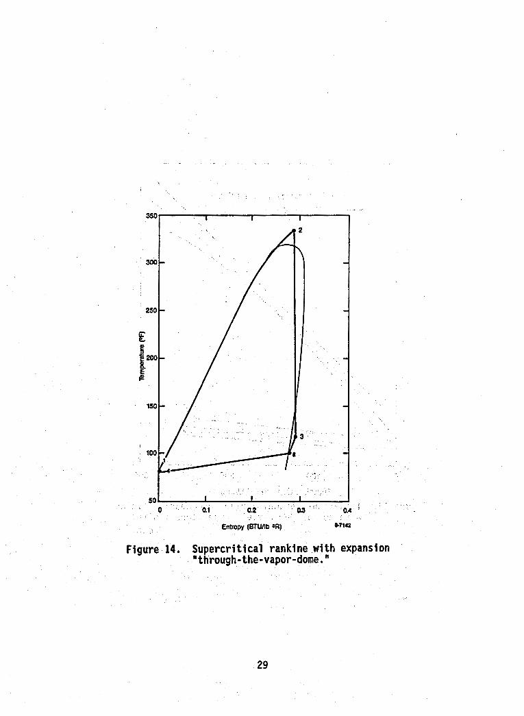
Figure 14, Supercritical rankine with expansion "through-the-vapor-dome. "
29

400
350
300
h
k. 250 E I
e
J
a - E 200
150
100
50
- Supercritical Rankine Cycle ---
---- I I
0 100 200 300 Enthalph Chance (BTUllb gee)
Figure 15. Temperature-enthalpy diagram comparing cycles , with no minimum outlet temperature limits.
06776
30

0 3 E 0
.-
0.8 C
Q)
co
.- z5 5 0.6 i
I B I-.
O l I I I 1 I I 200 240 280 320 360 400 440 480
Resource Temperature [OF]
Figure 16. Comparison no minimum
0.7150
between cycles with temperature 1 imi t.
31

countercurrent, integral condensation of a mixture in the Rankine cycle compared to the condensation of pure pentane in the Trilateral cycle.
There appear to be potential problems in executing the Trilateral cycle which are not present in the Supercritical Rankine cycle. inlet to outlet volume during the expansion process and the fact that the expanding working fluid is a two-phase mixture, three expanders in series are proposed for the trilateral cycle. State points on Figure 13 labeled a and b represent the intermediate points between expanders. This will entail the movement o f a two-phase mixture from one unit to another with the inherent added pressure drop and potential separation of the phases. The calculations for the Trilateral cycle also assume extremely high efficiencies for the expanders. The two high pressure expanders are to be helical screw expanders with efficiencies of 70 and 78% respectively. The low pressure expander is to be a Rotoflow turbine with an efficiency of 85%. Past experience with helical screw expanders in geothermal service indicated that the
Because of the large ratio of
assumed efficiencies will be considerably lower. expansion of the Supercritical Rankine cycle, no appreciable amount of liquid is expected to be encountered and, therefore, no degradation in turbine performance is expected. conducted to confirm the occurrence of this metastable state within the turbine.
In the "Through-the-Dome"
Experiments at the Heat Cycle Research facility are presently being
32
CONCLUSIONS
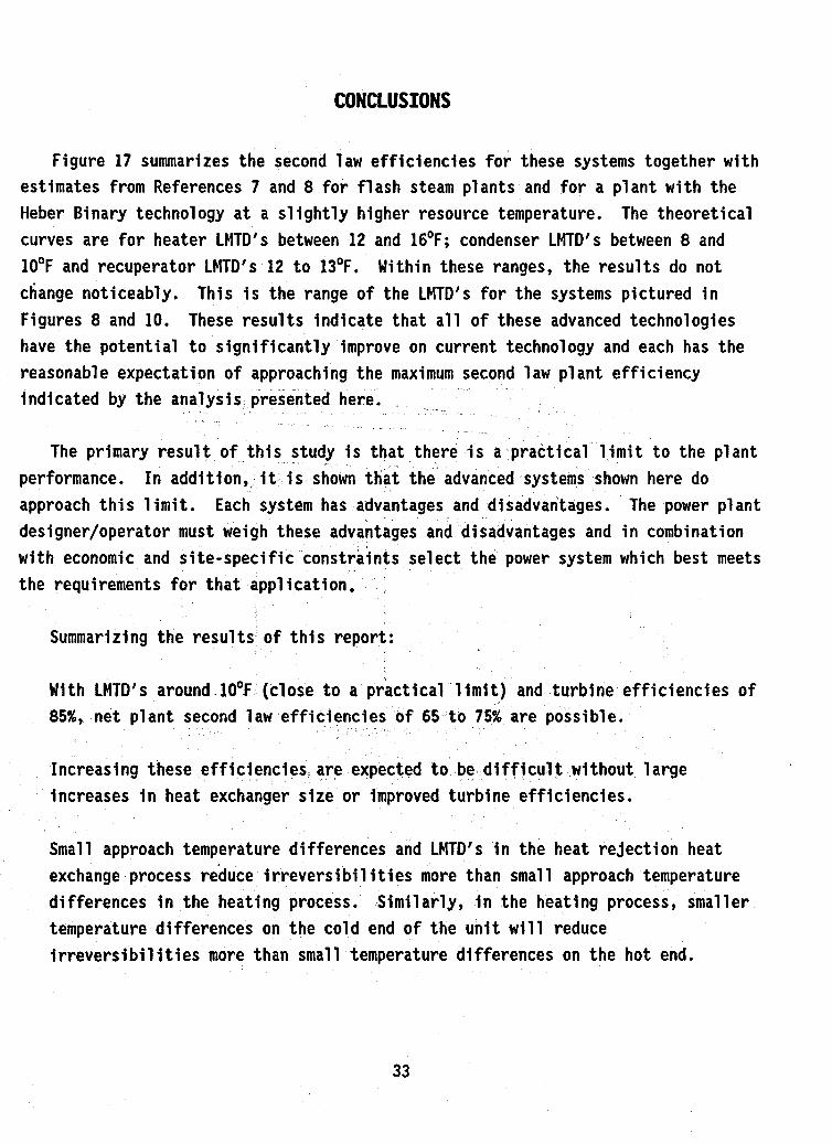
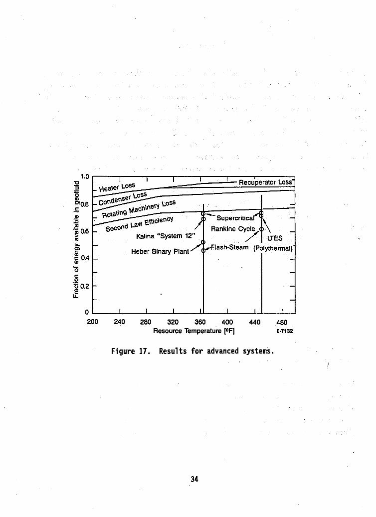
Figure 17 summarizes the second law efficiencies for these systems together with estimates from References 7 and 8 for flash steam plants and for a plant with the Heber Binary technology at a slightly higher resource temperature. The theoretical curves are for heater LMTD's between 12 and 16OF; condenser LMTD's between 8 and 10°F and recuperator LMTD's 12 to 13OF. Within these ranges, the results do not change noticeably. This is the range of the LMTD's for the systems pictured in Figures 8 and 10. These results indicate that all of these advanced technologies have the potential to significantly improve on current technology and each has the reasonable expectation of approaching the maximum second law plant efficiency indicated by the analysis presented here.
The primary result of this study is that there i s a practical limit to the plant
Each system has advantages and disadvantages. The power plant
nts select the power system which best meets
performance. In addition,, it is shown that the advanced systems shown here do approach this limit. designer/operator must weigh these advantages and disadvantages and in combination with economic and site-specific const the requirements for that application.
Summarizing the results of this report:
With LMTD's around 10°F (close to a practical limit) and turbine efficiencies of 85%, net plant second law efficiencies of 65 to 75% are possible.
Increasing these efficiencies. are expected to be difficult without large increases in heat exchanger size or improved turbine efficiencies.
Small approach temperature differences and LMTD's in the heat rejection heat exchange process reduce i rreversi bil i ties more than small approach temperature differences in the heating process. Similarly, in the heating process, smaller temperature differences on the cold end of the unit will reduce irreversibilities more than small temperature differences on the hot end.
33
i
1 .o 0 a
%0.8 c
a .g 0.6
- c. 0
- a2 Q - Q r Kalina "System 12"
Heber Binary Plant i E 0.4
r
Rankine Cyde,?\ 1 LTES
&lash-Steam (p ytherma!l
200 240 280 320 360 400 440 480 Resource Temperature [ O F ] 0.71 32
Figure 17. Results for advanced systems. i
I
34

Limits on geofluid outlet temperature (silica deposition limits) increase heat transfer irreversibil ities; recuperation decreases these irreversibil ities.
The different advanced systems considered here appear to be approaching this practical limit and investigation for a particular application may favor one system over another. The design engineer must decide on the,most cost-effective alternative based on all aspects of the systems.
This definition of practical limits does not include effects of heat source delivery systems or heat rejection systems. The geofluid supply and injection systems should be similar for .all binary alternatives, however the heat rejection systems may be different because of the optimum cooling water temperature rise (or air temperature rise for dry cooling). These effects must be addressed separately. Obviously, the higher the .geofluid effectiveness, the smaller the field necessary to support the plant and the less heat rejected, the smaller the heat rejection system will be to support the plant.
35

1.
2.
3.
4.
I 5.
6.
7.
8.
REFERENCES
Demuth, O.J., and Whitbeck, J.F., Advanced ConceDt Value Analvsis for Geothermal Power P1 ants, EGG-GTH-5821, March 1982.
Cassel, T. et al., Geothermal Well Field and Dower Plant Investment Decision Analvsis, DOE-ET-27242-T1, May 31, 1981.
Demuth, 0.3. , "Analysis of Binary Thermodynamic Cycles for a Moderately Low-Temperature Geothermal Resource, " Proceedinqs of the 15th IECEC, American Institute of Aeronautics and Astronautics, Vol. 1, pp. 798-803, 1980.
Demuth, O.J., "Analysis of Mixed Hydrocarbon Binary Thermodynamic Cycles for Moderate Temperature Geothermal Resources, 'I Proceedinqs of the 16th IECEC, American Society of Mechanical Engineers, Vol. 2, pp. 1316-1321, 1981.
Demuth, O.J. and Kochan, R.J., "Analysis of Mixed Hydrocarbon Binary Thermodynamic Cycles for Moderate Temperature Geothermal Resources Using Regenerative Techniques," Proceedinqs of 17th IECEC, Institute of Electrical and Electronics Engineers, Vol. 2, pp. 1104-1109, 1982.
Bliem, C.J., "Zeotropic Mixtures of Halocarbons as Working Fluids in Binary Geothermal Power Generation Cycles," Proceedinqs of the 22nd IECEC, American Institute of Aeronautics and Astronautics, Vol. 2, pp. 930-935, 1987.
Demuth, O.J., Bliem, C. J., Mines, G.L. and Swank, W.D., SuDercritical Binarv Geothermal Cvcle ExDeriments with Mixed-Hvdrocarbon Workina Fluids and a Vertical. In-Tube. Counterflow Condenser, EGG-EP-7076, Idaho National Engineering Laboratory, December 1985.
Bliem, C. J., and Mines, 6. L., "Relative Performance of Supercritical Binary Power Cycles With In-Tube Condensers in Different Orientations, " Proceedinqs of the 24th IECEC, Institute of Electrical and Electronic Engineers, Vol. 5, pp. 2167-2172, 1989.
36

9.
10.
11.
12.
13.
14.
15.
16.
17.
Kalina, A. I. and Leibowitr, H. M., "Application of the Kalina Cycle Technol ogy to Geothermal Power Generation, " Transactions of the Geothermal Resources Council, Vol. 13, pp. 553-559, 1989.
Saulson, S. H. and Rosenblatt, 3. H., "Analysis of Working Fluid Choices for Novel Cycle Applicable to Geothermal and Conventional Power Plants: An Interim Report," Proceedinss of 24th IECEC, Institute of Electrical and Electronics Engineers, Vol. 6, pp. 2789-2794, 1989.
Reference no. ETSU G 141, Hot Dry Rock Trilateral Wet VaDour Cycle Study, Project No. 4022-001, Energy Technol ogy Support Unit , Department of Energy, U. K.
Obert, E. F. , ConceDts of Thermodynamics, McGraw-Hill Book Company, Inc., New York, 1960, Chapter 15.
Kal ina, A. I., "Combined-Cycle System with Novel Bottoming Cycle," Journal for Enaineerina for Gas Turbines and Power, Vol. 106, pp. 737-742, 1984.
Bliem, C. J . , "Simple Strategies for Minimization of Cooling Water Usage in Binary Power Plants," Transactions o f the Geothermal Resources Council, Vol. 13, pp. 553-559, 1989.
Fyfe, W.S., Price, N.J., and Thompson, A.B., Fluids in th e Earth's Crust, Elsevier Scientific Pub1 ishing Company, Amsterdam-Oxford-New York, 1978, p. 75.
Demuth, O.J., "Preliminary Assessment of Condensation Behavior for Hydrocarbon Vapor Expansions Which Cross the Saturation Line Near the Critical Point," Proceedinss of the 18th IECEC, American Institute o f Chemical Engineers, Vol. 1, pp. 325-330, 1983.
Bliem, C. J . , PsDects of the Kalina Technoloav Amlied to Geothermal Power Production, INEL Report No. EGG-EP-8708, September 1989.

18. Elliott, D. G., Theorv and Tests on Two-phase Turbines, 3PL Publications 81- 105, DOE/ER-10614-1, March 1982;