ADTECH4 Series CNC Maintenance Manual 4...ADTECH4 Series CNC maintenance Manual - 4 - Install...
194
ADTECH4 Series CNC Maintenance Manual
Transcript of ADTECH4 Series CNC Maintenance Manual 4...ADTECH4 Series CNC maintenance Manual - 4 - Install...
ADTECH4 Series
CNC Maintenance Manual
ADTECH4 Series CNC maintenance Manual
- 2 -
Basic Information
This Manual is written by Adtech (Shenzhen) Technology Co., Ltd.
This Manual is mainly written by: Tang Xiaobing
This Manual was first released on August 27, 2013, with version No. A0101 and item number
BZ001B092A.
Copyright Notice
The property rights of all the parts of the manual belong to Adtech (Shenzhen) Technology Co., Ltd.
(Adtech for short), and any form of imitation, copying, transcription or translation by any company or
individual without the permission is prohibited. This manual does not include any form of assurance,
standpoint expression, or other intimations. Adtech and the stuffs have no responsibility for any direct or
indirect disclosure of the information, benefit loss or business termination of this manual of the quoted
product information. In addition, the product and the information mentioned in this manual are for
reference only, and the content is subject to change without notice.
ALL RIGHTS RESERVED!
Adtech (Shenzhen) Technology Co., Ltd.
ADTECH4 Series CNC maintenance Manual
- 3 -
Precautions and Explanations
※Transport and storage:
Do not stack product package more than six layers;
Do not climb, stand on or place heavy stuff on the product package;
Do not pull the cable still connecting with machine to move product.
Forbid impact and scratch on the panel and display;
Prevent the product package from humidity, sun exposure, and rain.
※Open-box inspection:
Open the package to confirm the product to be purchased by you.
Check damages situation after transportation;
Confirm the integrity of parts comparing with the parts list or damages situation;
Contact our company promptly for discrepant models, shortage accessories, or transport damages.
※Wiring
Ensure the persons involved into wiring and inspecting are specialized staff;
Guarantee the product is grounded with less than 4Ω grounding resistance. Do not use neutral
line (N) to substitute earth wire.
Ensure grounding to be correct and solid, in order to avoid product failures or unexpected
consequences;
Connect the surge absorption diodes to the product in the required direction, otherwise, the
product will be damaged;
Ensure the power switch is OFF before inserting or removing plug, or disassembling chassis.
※Overhauling
Ensure the power is OFF before overhauling or components replacement;
Make sure to check failures after short circuit or overloading, and then restart the machine after
troubleshooting
Do not allow to frequently connect and disconnect the power, and at least one minute interval
between power-on and power-off.
※Miscellaneous
Do not open housing without permission;
Keep power OFF if not in use for a long time;
Pay close attention to keep dust and ferrous powder away from control;
Fix freewheel diode on relay coil in parallel if non-solid state relay is used as output relay. Check
whether power supply meets the requirement to ensure not burning the control.
ADTECH4 Series CNC maintenance Manual
- 4 -
Install cooling fan if processing field is in high temperature, due to close relationship between
service life of the control and environmental temperature. Keep proper operative temperature
range for the control: 0℃ ~ 60℃.
Avoid using the product in the overheating, humid, dusty, or corrosive environments;
Add rubber rails as cushion on the place with strong vibration.
※Maintenance:
Please implement routine inspection and regular check upon the following items, under the general
usage conditions (i.e. environmental condition: daily average 30℃, load rate: 80%, and operating rate: 12
hours/ day)
Routine
Inspection Routine
Confirm environmental temperature, humidity, dust, or
foreign objects.
Confirm abnormal vibration and noise;
Check whether vents are blocked by yarn etc.
Regular Check One
year
Check whether solid components are loose
Confirm whether terminal block is damaged
ADTECH4 Series CNC maintenance Manual
- 5 -
Contents
1. Foreword .......................................................................................................................... - 10 -
2. System Technical Features...............................................................................................- 11 -
2.1 Technical Parameters .............................................................................................................. - 11 -
2.2 System Functions ................................................................................................................... - 13 -
2.2.1. Self-diagnosis ............................................................................................................................................. - 13 -
2.2.2. Compensation ............................................................................................................................................. - 13 -
2.2.3. Abundant Instruction System ..................................................................................................................... - 13 -
2.2.4. Full Chinese Menu Operation & Full Screen Edit ...................................................................................... - 13 -
2.2.5. Abundant Error-correction Functions ......................................................................................................... - 13 -
2.2.6. Program Exchange between CNC System and PC ..................................................................................... - 14 -
2.3 System Operating Condition .................................................................................................. - 14 -
3. Operating Panel ............................................................................................................... - 15 -
3.1 ADTCNC46 Series System LCD/ Button Panel .................................................................... - 15 -
LCD display unit .................................................................................................................... - 16 -
3.2 ADTCNC49 Series System LCD/ Button Panel .................................................................... - 17 -
3.3 System Menus ........................................................................................................................ - 17 -
3.3.1. Auto-monitor submenu ............................................................................................................................... - 18 -
3.3.2. Program editing submenu ........................................................................................................................... - 19 -
3.3.3. Parameters submenu ................................................................................................................................... - 19 -
3.3.4. Working coordinate submenu ..................................................................................................................... - 20 -
3.3.5. Diagnosis submenu ..................................................................................................................................... - 21 -
3.4 Operating Keys ....................................................................................................................... - 22 -
4. Manual Operation ........................................................................................................... - 23 -
4.1 Returning to reference point manually ................................................................................... - 23 -
4.2 Continuous Feeding Manually ............................................................................................... - 24 -
4.3 Single Step Feeding ................................................................................................................ - 25 -
4.4 Hand wheel feeding ................................................................................................................ - 25 -
4.5 Manual auxiliary function operation ...................................................................................... - 27 -
4.6 Tool setting ............................................................................................................................. - 28 -
4.6.1. Centered (M series) .................................................................................................................................... - 28 -
(1) Single axis centered .......................................................................................................... - 29 -
ADTECH4 Series CNC maintenance Manual
- 6 -
(2) Square centered ................................................................................................................ - 29 -
(3) Plane circle (XY plane) centered ..................................................................................... - 29 -
4.6.2. Tool regulator (M series) ............................................................................................................................ - 31 -
4.6.3. Tool setting by test cutting (L series) .......................................................................................................... - 31 -
4.7 Data settings ........................................................................................................................... - 32 -
4.7.1. Tool compensation data setting ................................................................................................................... - 32 -
4.7.2. System parameter setting ............................................................................................................................ - 32 -
4.8 System shortcuts ..................................................................................................................... - 33 -
5. Automatic Operation ...................................................................................................... - 34 -
5.1 Memory Operation ................................................................................................................. - 34 -
5.2 MDI Operation ....................................................................................................................... - 34 -
5.3 USB disk DNC ....................................................................................................................... - 35 -
5.4 Speed rate adjustment ............................................................................................................. - 35 -
5.5 Run idle .................................................................................................................................. - 36 -
5.6 SBK Function ......................................................................................................................... - 36 -
5.7 BDT function .......................................................................................................................... - 36 -
5.8 Stopping Automatic Operating ............................................................................................... - 36 -
6. Safe Operation ................................................................................................................. - 38 -
6.1 Emergency Stop...................................................................................................................... - 38 -
6.2 Hard Limit Over Travel .......................................................................................................... - 38 -
6.3 Soft Limit Over Travel ........................................................................................................... - 38 -
7. Alarm and Self-diagnosis Function ............................................................................... - 39 -
7.1 NC Program Execution Alarm ................................................................................................ - 39 -
7.2 System Environment Alarms .................................................................................................. - 41 -
7.3 Alarm processing .................................................................................................................... - 43 -
7.4 Self-diagnosis ......................................................................................................................... - 43 -
8. Program Saving & Editing ............................................................................................. - 44 -
8.1 Saving the Program in the Memory ........................................................................................ - 44 -
8.1.1. Keypad Input (New Program) .................................................................................................................... - 44 -
8.1.2. PC Serial Port Input .................................................................................................................................... - 44 -
8.1.3. Copying Processing Files from USB Disk .................................................................................................. - 44 -
8.2 Reading Programs into Work Area ......................................................................................... - 44 -
ADTECH4 Series CNC maintenance Manual
- 7 -
8.2.1. Reading Programs from Controller into Work Area ................................................................................... - 44 -
8.2.2. Reading Programs from USB Disk into Work Area .................................................................................... - 45 -
8.3 Editing & Modifying Programs .............................................................................................. - 45 -
8.4 Deleting Files ......................................................................................................................... - 45 -
8.4.1. Deleting Files in Memory ........................................................................................................................... - 45 -
9. Main Interfaces of the System ........................................................................................ - 46 -
9.1 Position Interface .................................................................................................................... - 46 -
9.2 Programming Interface ........................................................................................................... - 49 -
9.3 MDI interface ......................................................................................................................... - 51 -
MDI interaction interface is shown below: .......................................................................... - 51 -
MDI interaction interface ...................................................................................................... - 51 -
9.4 File Management .................................................................................................................... - 52 -
9.5 Graphic Simulation ................................................................................................................. - 53 -
9.6 Parameter Interface ................................................................................................................. - 54 -
IO configuration parameters ................................................................................................ - 57 -
IO Configuration Parameters Interface ............................................................................... - 58 -
9.7 Compensation interface .......................................................................................................... - 58 -
9.8 M series workpiece coordinate system setting interface ........................................................ - 59 -
9.9 Controller Diagnosis Interface (Diagnosis) ............................................................................ - 62 -
9.10 Macro Variable View Interface (Macro Variable) ................................................................... - 63 -
9.11 Current mode instruction info ................................................................................................ - 63 -
10. System Maintenance ....................................................................................................... - 65 -
10.1 Restart ..................................................................................................................................... - 65 -
10.2 System Upgrade ..................................................................................................................... - 65 -
10.3 Reset ....................................................................................................................................... - 65 -
10.4 Parameter Backup & Restore ................................................................................................. - 65 -
10.5 Entering BISO Interface ......................................................................................................... - 66 -
11. System Parameters .......................................................................................................... - 67 -
11.1 Parameter Index List .............................................................................................................. - 68 -
11.2 General parameter (P1.).......................................................................................................... - 97 -
11.3 Axis parameter configuration (P2.) ...................................................................................... - 113 -
11.4 Management parameter (P3.) ............................................................................................... - 133 -
ADTECH4 Series CNC maintenance Manual
- 8 -
11.5 Tool magazine parameters (P4.) ........................................................................................... - 139 -
11.6 Spindle axis parameter (P5.) ................................................................................................. - 140 -
11.7 Port configuration (P6.) ........................................................................................................ - 145 -
12. Hardware Interface Definition and Connection Instructions ................................... - 148 -
12.1 Installation Layout ................................................................................................................ - 148 -
12.1.1. 46 Series External Interface Diagram ..................................................................................................... - 148 -
12.1.2. 49 Series External Interface Diagram ..................................................................................................... - 148 -
12.1.3. 46 Series Mounting dimensions .............................................................................................................. - 149 -
12.1.4. 49 Series Mounting dimensions .............................................................................................................. - 150 -
12.1.5. Installation precautions ........................................................................................................................... - 152 -
12.2 Interface Definition .............................................................................................................. - 154 -
12.2.1. Motor Drive Control Interface ................................................................................................................ - 154 -
12.2.2. Digital input interface ............................................................................................................................. - 157 -
Default input port configuration of 46M series XS7 (milling machine) .......................... - 159 -
Default input port configuration of 46L series XS5 (lathe) .............................................. - 160 -
Default input port configuration of 49M series XS7 (milling machine) .......................... - 161 -
12.2.3. Digital output interface ........................................................................................................................... - 165 -
Default output port configuration of M series milling machine CNC4640(XS6),
CNC4960(XS8) ..................................................................................................................... - 167 -
Default output port configuration of M series milling machine CNC4960(XS15) ......... - 168 -
Default output port configuration of L series (lathe) ........................................................ - 170 -
12.2.4. Handheld box interface ........................................................................................................................... - 170 -
12.2.5. Analog output interface (46 series XS8) ................................................................................................. - 174 -
12.2.6. Spindle axis encoder interface (46 series XS12, 49 series XS10) ........................................................... - 175 -
12.2.7. RS232 transmission interface (46 series XS9, 49 series XS11) .............................................................. - 180 -
12.2.8. USB memory connection interface (46 series XS10) ............................................................................. - 180 -
12.2.9. PC USB communication interface (46 series XS11, 49 series X13) ....................................................... - 180 -
12.3 Electrical connection diagram .............................................................................................. - 180 -
12.3.1. Symbol schematic diagram ..................................................................................................................... - 180 -
12.3.2. Power connection diagram ..................................................................................................................... - 182 -
12.3.3. Servo drive connection diagram ............................................................................................................. - 183 -
12.3.4. Step connection diagram ........................................................................................................................ - 184 -
ADTECH4 Series CNC maintenance Manual
- 9 -
12.3.5. IO electrical connection diagram ............................................................................................................ - 185 -
12.3.6. ADT9163 splitter wiring diagram ........................................................................................................... - 187 -
12.3.7. ET102A splitter wiring diagram ............................................................................................................. - 191 -
ET102A splitter function definition .................................................................................... - 191 -
12.3.8. ET202A splitter wiring diagram ............................................................................................................. - 193 -
ET202A splitter function definition .................................................................................... - 193 -
ADTECH4 Series CNC maintenance Manual
- 10 -
1. Foreword
CNC4 series numerical control system is economic embedded system developed by Adtech (Shenzhen)
Technology Co., Ltd. for lathes, milling machines and machining centers, where CNC4640 and 4940 are four
axes motion controllers, CNC4960 is six axes motion controller and CNC4620 is two axes motion controller.
Instructions and reading convention of the Manual
Before using this CNC system, please read this Manual carefully to operate properly.
Explanation of terms and reading conventions of this manual:
CNC4640 and CNC4620 are control systems with different axes but same hardware functions. M Series
applications for milling machines and L Series applications for lathes are developed on this platform. The
applications differ on functions and interfaces.
M series refers to a system for milling machine motion function. The interfaces and functions followed by
a 'M' or "M Series" note are dedicated for the software system of milling machines.
L series refers to a system for lathe motion function. The interfaces and functions followed by an 'L' or "L
Series" note are dedicated for the lathe software system.
"CNC system", "NC controller" and "CNC46XX" mentioned in this manual refer to CNC4640/4620;
"Note" indicates prompt for the operator in related operations or settings, or else it may cause operation
failure or an action cannot be executed.
ADTECH4 Series CNC maintenance Manual
- 11 -
2. System Technical Features
2.1 Technical Parameters
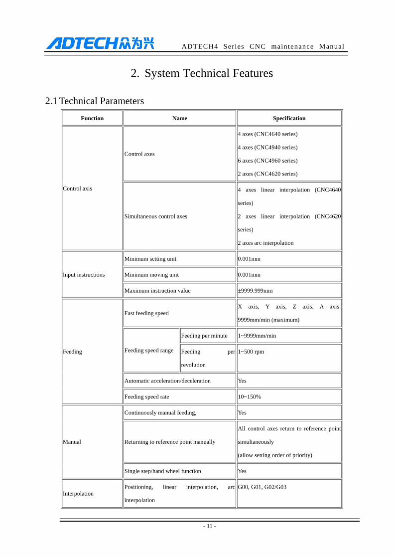
Function Name Specification
Control axis
Control axes
4 axes (CNC4640 series)
4 axes (CNC4940 series)
6 axes (CNC4960 series)
2 axes (CNC4620 series)
Simultaneous control axes
4 axes linear interpolation (CNC4640
series)
2 axes linear interpolation (CNC4620
series)
2 axes arc interpolation
Input instructions
Minimum setting unit 0.001mm
Minimum moving unit 0.001mm
Maximum instruction value ±9999.999mm
Feeding
Fast feeding speed X axis, Y axis, Z axis, A axis:
9999mm/min (maximum)
Feeding speed range
Feeding per minute 1~9999mm/min
Feeding per
revolution
1~500 rpm
Automatic acceleration/deceleration Yes
Feeding speed rate 10~150%
Manual
Continuously manual feeding, Yes
Returning to reference point manually
All control axes return to reference point
simultaneously
(allow setting order of priority)
Single step/hand wheel function Yes
Interpolation Positioning, linear interpolation, arc
interpolation
G00, G01, G02/G03
ADTECH4 Series CNC maintenance Manual
- 12 -
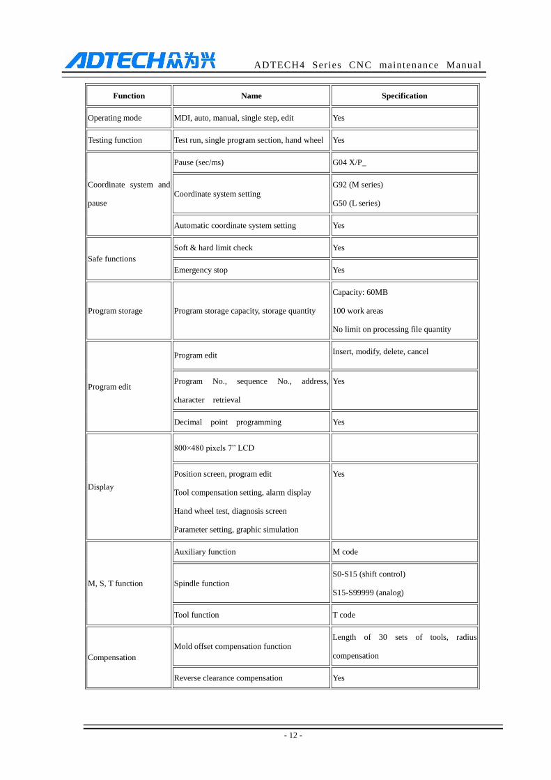
Function Name Specification
Operating mode MDI, auto, manual, single step, edit Yes
Testing function Test run, single program section, hand wheel Yes
Coordinate system and
pause
Pause (sec/ms) G04 X/P_
Coordinate system setting G92 (M series)
G50 (L series)
Automatic coordinate system setting Yes
Safe functions
Soft & hard limit check Yes
Emergency stop Yes
Program storage Program storage capacity, storage quantity
Capacity: 60MB
100 work areas
No limit on processing file quantity
Program edit
Program edit Insert, modify, delete, cancel
Program No., sequence No., address,
character retrieval
Yes
Decimal point programming Yes
Display
800×480 pixels 7” LCD
Position screen, program edit
Tool compensation setting, alarm display
Hand wheel test, diagnosis screen
Parameter setting, graphic simulation
Yes
M, S, T function
Auxiliary function M code
Spindle function S0-S15 (shift control)
S15-S99999 (analog)
Tool function T code
Compensation
Mold offset compensation function Length of 30 sets of tools, radius
compensation
Reverse clearance compensation Yes
ADTECH4 Series CNC maintenance Manual
- 13 -
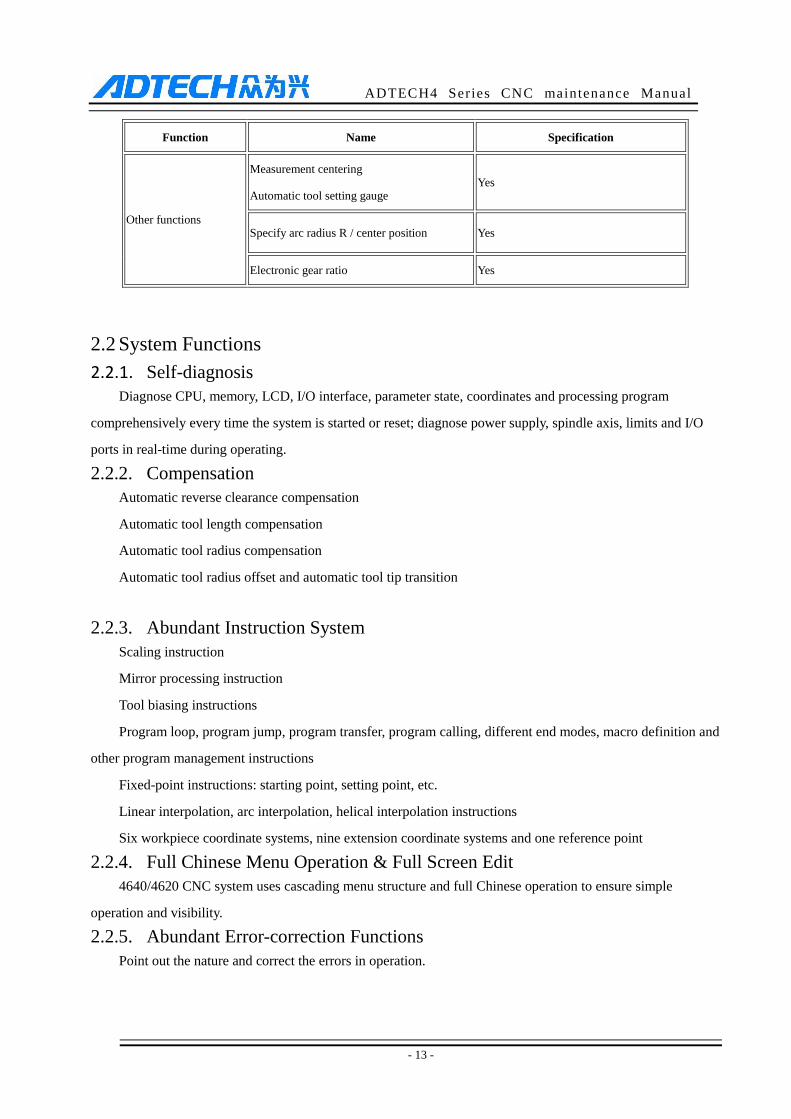
Function Name Specification
Other functions
Measurement centering
Automatic tool setting gauge Yes
Specify arc radius R / center position Yes
Electronic gear ratio Yes
2.2 System Functions
2.2.1. Self-diagnosis Diagnose CPU, memory, LCD, I/O interface, parameter state, coordinates and processing program
comprehensively every time the system is started or reset; diagnose power supply, spindle axis, limits and I/O
ports in real-time during operating.
2.2.2. Compensation
Automatic reverse clearance compensation
Automatic tool length compensation
Automatic tool radius compensation
Automatic tool radius offset and automatic tool tip transition
2.2.3. Abundant Instruction System
Scaling instruction
Mirror processing instruction
Tool biasing instructions
Program loop, program jump, program transfer, program calling, different end modes, macro definition and
other program management instructions
Fixed-point instructions: starting point, setting point, etc.
Linear interpolation, arc interpolation, helical interpolation instructions
Six workpiece coordinate systems, nine extension coordinate systems and one reference point
2.2.4. Full Chinese Menu Operation & Full Screen Edit
4640/4620 CNC system uses cascading menu structure and full Chinese operation to ensure simple
operation and visibility.
2.2.5. Abundant Error-correction Functions
Point out the nature and correct the errors in operation.
ADTECH4 Series CNC maintenance Manual
- 14 -
2.2.6. Program Exchange between CNC System and PC
Perform CAD/CAM/CAPP auxiliary programming with abundant software in PC, and then transmit CNC
program to the system through communication interface (USB disk, RS232 interface), or transmit the programs
from the system to PC.
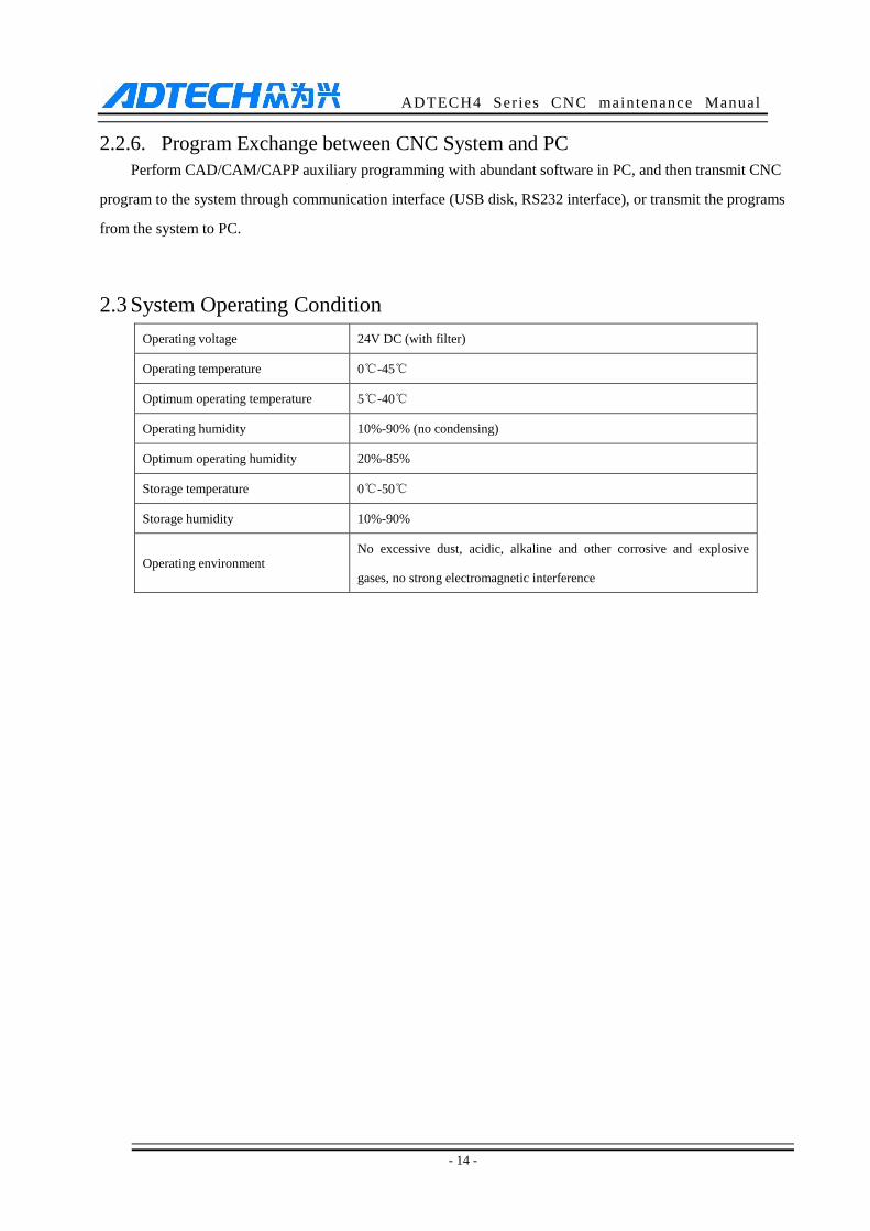
2.3 System Operating Condition
Operating voltage 24V DC (with filter)
Operating temperature 0℃-45℃
Optimum operating temperature 5℃-40℃
Operating humidity 10%-90% (no condensing)
Optimum operating humidity 20%-85%
Storage temperature 0℃-50℃
Storage humidity 10%-90%
Operating environment No excessive dust, acidic, alkaline and other corrosive and explosive
gases, no strong electromagnetic interference
ADTECH4 Series CNC maintenance Manual
- 15 -
3. Operating Panel
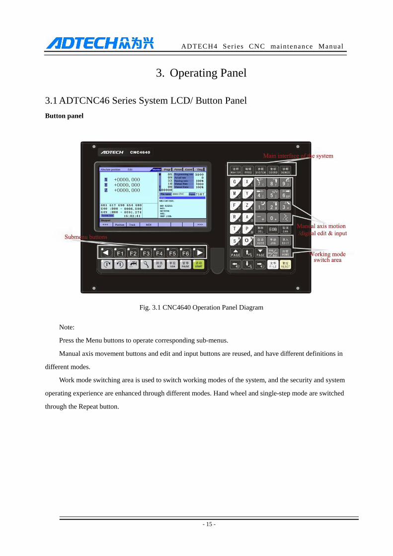
3.1 ADTCNC46 Series System LCD/ Button Panel
Button panel
Fig. 3.1 CNC4640 Operation Panel Diagram
Note:
Press the Menu buttons to operate corresponding sub-menus.
Manual axis movement buttons and edit and input buttons are reused, and have different definitions in
different modes.
Work mode switching area is used to switch working modes of the system, and the security and system
operating experience are enhanced through different modes. Hand wheel and single-step mode are switched
through the Repeat button.
ADTECH4 Series CNC maintenance Manual
- 16 -
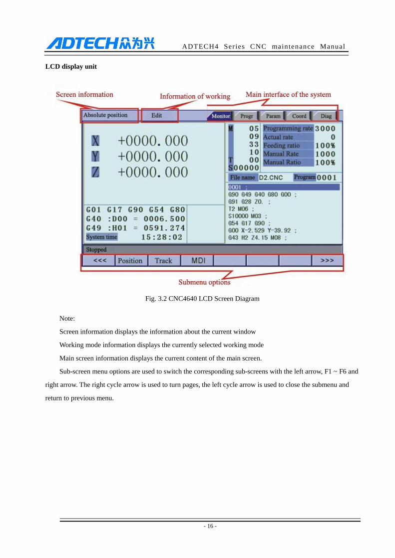
LCD display unit
Fig. 3.2 CNC4640 LCD Screen Diagram
Note:
Screen information displays the information about the current window
Working mode information displays the currently selected working mode
Main screen information displays the current content of the main screen.
Sub-screen menu options are used to switch the corresponding sub-screens with the left arrow, F1 ~ F6 and
right arrow. The right cycle arrow is used to turn pages, the left cycle arrow is used to close the submenu and
return to previous menu.

ADTECH4 Series CNC maintenance Manual
- 17 -
3.2 ADTCNC49 Series System LCD/ Button Panel
3.3 System Menus
CNC46XX system uses cascading menu structure. You can press the following keys to operate the menus.
Press a key to show the corresponding content in the bottom of the LCD.
ADTECH4 Series CNC maintenance Manual
- 18 -
Key in the left: Return to previous menu
Key in the right: Turn pages to show other menus of same level
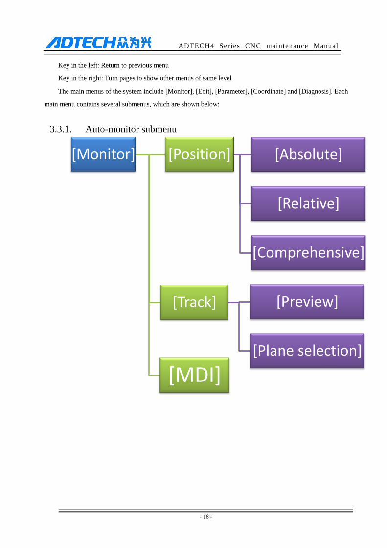
The main menus of the system include [Monitor], [Edit], [Parameter], [Coordinate] and [Diagnosis]. Each
main menu contains several submenus, which are shown below:
3.3.1. Auto-monitor submenu
[Monitor] [Position] [Absolute]
[Relative]
[Comprehensive]
[Track] [Preview]
[Plane selection]
[MDI]
ADTECH4 Series CNC maintenance Manual
- 19 -
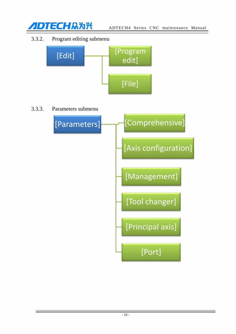
3.3.2. Program editing submenu
3.3.3. Parameters submenu
[Edit] [Program
edit]
[File]
[Parameters] [Comprehensive]
[Axis configuration]
[Management]
[Tool changer]
[Principal axis]
[Port]
ADTECH4 Series CNC maintenance Manual
- 20 -
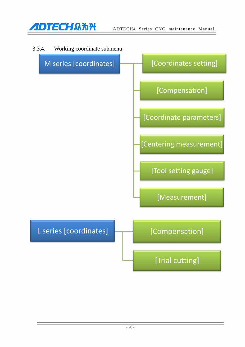
3.3.4. Working coordinate submenu
M series [coordinates] [Coordinates setting]
[Compensation]
[Coordinate parameters]
[Centering measurement]
[Tool setting gauge]
[Measurement]
L series [coordinates] [Compensation]
[Trial cutting]
ADTECH4 Series CNC maintenance Manual
- 21 -
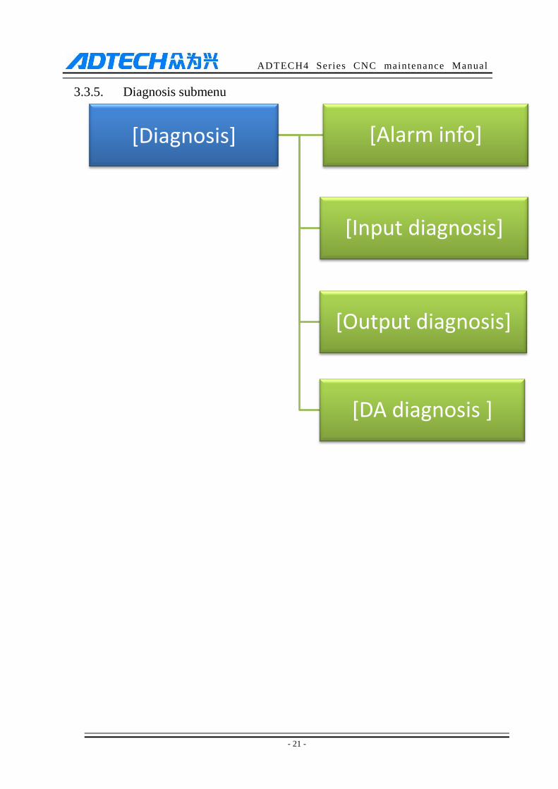
3.3.5. Diagnosis submenu
[Diagnosis] [Alarm info]
[Input diagnosis]
[Output diagnosis]
[DA diagnosis ]
ADTECH4 Series CNC maintenance Manual
- 22 -
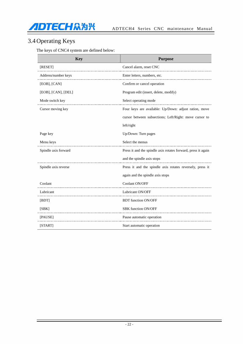
3.4 Operating Keys
The keys of CNC4 system are defined below:
Key Purpose
[RESET] Cancel alarm, reset CNC
Address/number keys Enter letters, numbers, etc.
[EOB], [CAN] Confirm or cancel operation
[EOB], [CAN], [DEL] Program edit (insert, delete, modify)
Mode switch key Select operating mode
Cursor moving key Four keys are available: Up/Down: adjust ration, move
cursor between subsections; Left/Right: move cursor to
left/right
Page key Up/Down: Turn pages
Menu keys Select the menus
Spindle axis forward Press it and the spindle axis rotates forward, press it again
and the spindle axis stops
Spindle axis reverse Press it and the spindle axis rotates reversely, press it
again and the spindle axis stops
Coolant Coolant ON/OFF
Lubricant Lubricant ON/OFF
[BDT] BDT function ON/OFF
[SBK] SBK function ON/OFF
[PAUSE] Pause automatic operation
[START] Start automatic operation
ADTECH4 Series CNC maintenance Manual
- 23 -
4. Manual Operation
4.1 Returning to reference point manually
CNC machine tool has specific mechanical position, which is called as reference point and for tool
exchange and coordinates setting. Generally, when the power supply is connected, the tool should be moved to
the reference point. This operation is also called as home operation, which will make the CNC system confirm
the origin of machine tool.
The home operation includes program and mechanical mode:
For program home, the action completes when the coordinates of machine tool are 0, and won’t check
whether origin switch is in position;
For mechanical home, the external home sensor switch is used to locate the origin of the machine tool; two
checking modes are available:
With the external sensor switch, the home operation completes when the sensing is successfully repeatedly.
The external sensor switch is used as deceleration switch, the servo home is enabled as home signal after
sensing and then the sensing stops. You can set the “Home mode” in [Parameter] [Comprehensive Parameter],
in which 0 (default) indicates program and 1 indicates mechanical. You can also press [SBK] key in home mode
to switch among “Mechanical – Program – Mechanical…” quickly. This method doesn’t conflict with parameter
setting. You can select accordingly. To use servo home as the home signal, you need to set “Axis phase Z home
enable” to “1” in [Parameter][Axis Configuration] in mechanical home mode, and the setting will take effect in
next home checking.
Several methods are available for tool returning to reference point and the steps follow:
(1) Each axis returns to reference point separately
Press the mode switch key [Home] to select home operation;
Press the composite key [X-], [Y-], [Z-], [A-] in the numbers section to return the corresponding axis to
reference point.
(2) The axes return to reference point simultaneously
Press the mode switch key [Home] to select home operation;
Press the [Start] key to return Z axis to reference point, and other axes return to reference point
simultaneously. The automatic home sequence can be configured in the parameters.
(3) Reset machine tool position
Press the mode switch key [Home] to select home operation;
In [Absolute Position] and [Coordinate System] screen, press [X], [Y], [Z], [A] key respectively to
show the value of corresponding axis position, and then press the [Cancel] key to reset the machine tool
ADTECH4 Series CNC maintenance Manual
- 24 -
position of current axis, i.e. current point is used as machine tool origin. After this operation, the system
considers it as a home action. Therefore, when the program is running, the alarm of not home won’t
occur. If you press by mistake, it will switch the screen and cancel selection automatically.
(4) Reset relative position manually
Press the mode switch key [Manual] to select manual operation;
In [Relative Position] and [Coordinate System] screen, press [X], [Y], [Z], [A] key respectively to show
the value of corresponding axis, and then press the [Cancel] key to reset the relative position of current
axis.
Note
The tool also can return to reference point according to program instruction, i.e. returning to reference point
automatically.
Caution:
Generally, the system will perform home operation after connecting the power supply. If the power fails while
the machine tool is moving, the system also will return to reference point when the power supply is connected
again. First return the z-axis to avoid collision of the tool and workpiece, which will result in damage to the tool,
workpiece and fixture.
4.2 Continuous Feeding Manually
Press the keys on the operation panel or hand wheel to move the tool along every axis.
The operation follows:
(1) Press the mode switch key [Manual] to select manual operation;
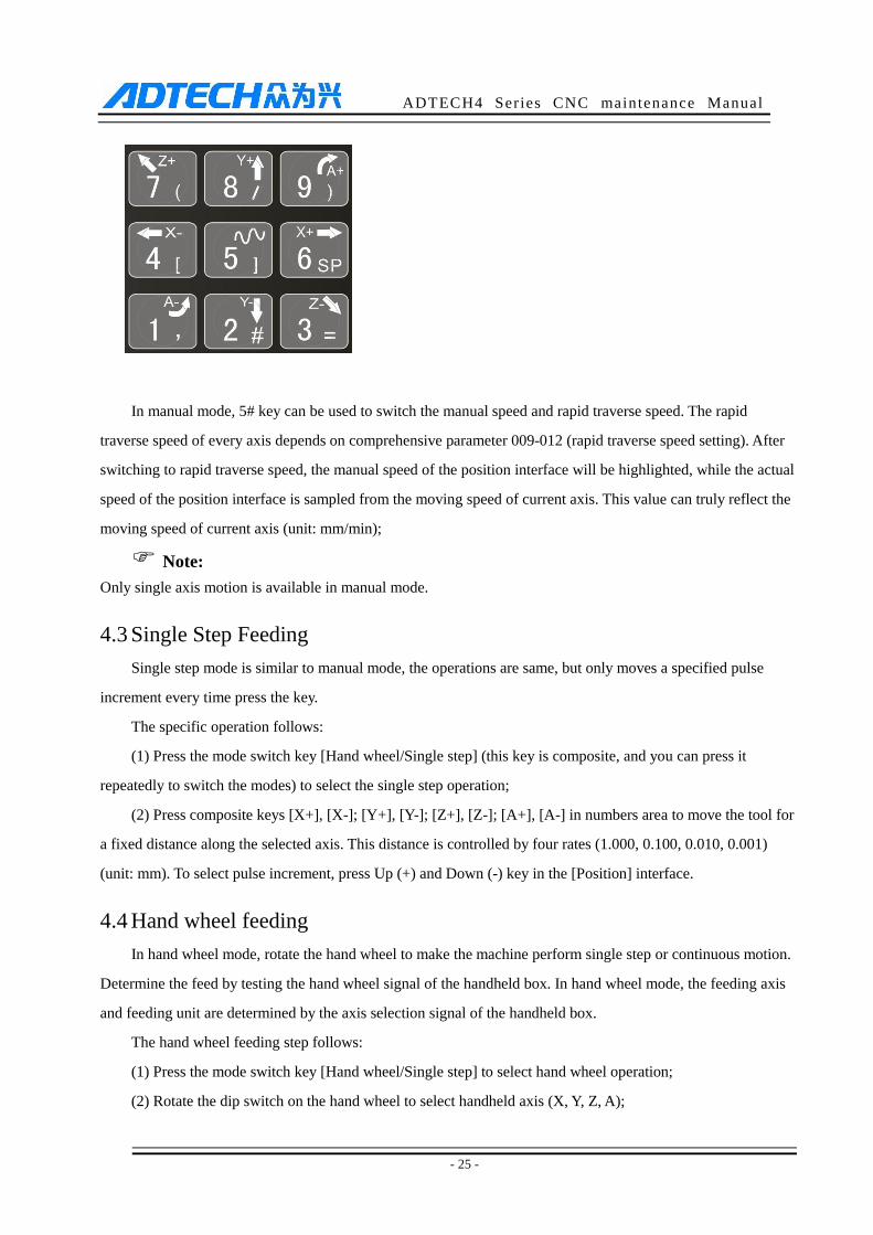
(2) Press composite keys [X+], [X-]; [Y+], [Y-]; [Z+], [Z-]; [A+], [A-] in numbers area to move the tool
along selected axis. The keypad follows:
ADTECH4 Series CNC maintenance Manual
- 25 -
In manual mode, 5# key can be used to switch the manual speed and rapid traverse speed. The rapid
traverse speed of every axis depends on comprehensive parameter 009-012 (rapid traverse speed setting). After
switching to rapid traverse speed, the manual speed of the position interface will be highlighted, while the actual
speed of the position interface is sampled from the moving speed of current axis. This value can truly reflect the
moving speed of current axis (unit: mm/min);
Note:
Only single axis motion is available in manual mode.
4.3 Single Step Feeding
Single step mode is similar to manual mode, the operations are same, but only moves a specified pulse
increment every time press the key.
The specific operation follows:
(1) Press the mode switch key [Hand wheel/Single step] (this key is composite, and you can press it
repeatedly to switch the modes) to select the single step operation;
(2) Press composite keys [X+], [X-]; [Y+], [Y-]; [Z+], [Z-]; [A+], [A-] in numbers area to move the tool for
a fixed distance along the selected axis. This distance is controlled by four rates (1.000, 0.100, 0.010, 0.001)
(unit: mm). To select pulse increment, press Up (+) and Down (-) key in the [Position] interface.
4.4 Hand wheel feeding
In hand wheel mode, rotate the hand wheel to make the machine perform single step or continuous motion.
Determine the feed by testing the hand wheel signal of the handheld box. In hand wheel mode, the feeding axis
and feeding unit are determined by the axis selection signal of the handheld box.
The hand wheel feeding step follows:
(1) Press the mode switch key [Hand wheel/Single step] to select hand wheel operation;
(2) Rotate the dip switch on the hand wheel to select handheld axis (X, Y, Z, A);
ADTECH4 Series CNC maintenance Manual
- 26 -
(3) Rotate the increment dip switch on the hand wheel to select the moving amount (0.1, 0.01, 0.001);
(4) Rotate the hand wheel to move the machine tool. The tool moves certain distance every time you rotate
the hand wheel for a scale. (For example, if you select X axis in step ⑵ and select 0.01 in step ⑶, the tool
moves 0.01mm every scale). Rotate the handle continuously to move the machine tool on this axis continuously.
Note:
The hand wheel feeding mode controls only one coordinate axis every time; the faster the hand wheel rotates,
the faster the machine tool moves.

ADTECH4 Series CNC maintenance Manual
- 27 -
4.5 Manual auxiliary function operation
Coolant on/off
In hand wheel/single step/manual mode, press this key to switch on/off the coolant.
Key indicator: No matter in what mode, the key indicator is on if only the coolant is on, or else the
indicator is off.
Lubricant on/off
In hand wheel/single step/manual mode, press this key to switch on/off the lubricant.
Key indicator: No matter in what mode, the key indicator is on if only the lubricant is on, or else the
indicator is off.
Spindle axis positive rotation/stop
In hand wheel/single step/manual mode, press this key to rotate the spindle axis positively and
press it again to stop the axis.
Key indicator: No matter in what mode, the key indicator is on if only the spindle axis is positive rotating,
or else the indicator is off.
Spindle axis reverse rotation/stop
In hand wheel/single step/manual mode, press this key to rotate the spindle axis reversely and
press it again to stop the axis.
Key indicator: No matter in what mode, the key indicator is on if only the spindle axis is reverse rotating,
or else the indicator is off.
General instructions for manual operation keys
Coolant, lubricant, spindle axis positive/reverse rotation are available in hand wheel, single step and
manual mode;
When the spindle axis is rotating, press the reverse rotation key, the spindle axis will stop first, and rotate
in reverse direction after pressing it again.
ADTECH4 Series CNC maintenance Manual
- 28 -
When auxiliary output is on, if the system is switched to another mode, the output remains unchanged;
press the 'Reset' button to turn it off, or execute the corresponding M code in automatic mode to turn off
corresponding output, or execute the corresponding M code in MDI interface to turn off corresponding output;
When the spindle axis is positive/reverse rotating and execute M04/M03 directly, the system first stops
positive/reverse rotating and then execute M04/M03 instruction;
Positive/reverse rotating of spindle is stopped while emergency stop, and other outputs can be set
according to system parameters.
4.6 Tool setting
Tool setting is the main operation and important skill during CNC processing. Under certain conditions,
tool setting precision can determine the processing precision of parts, and the tool setting efficiency also affects
the CNC processing efficiency directly. CNC46XX has M series tool setting mode and L series tool setting
mode, while M series has two tool setting methods, i.e. centered and tool regulator, and L series uses test
cutting.
4.6.1. Centered (M series)
The centered function is that the system calculates the center position of the workpiece automatically while
tool setting to realize segment centered, rectangle centered and circle center location.
Note
In the tool setting operation below, if the auxiliary parameters of the coordinate system doesn’t need setting, the
first three steps can be omitted. Please refer to chapter 9.5 for auxiliary parameters of the coordinate system.

ADTECH4 Series CNC maintenance Manual
- 29 -
(1) Single axis centered
Select the edit mode;
Press [Coordinates], [Coordinates Parameter] to enter the auxiliary parameters setting interface of the
coordinate system;
Move the cursor to desired position, enter new parameters and press [EOB] ;
Select hand wheel or manual mode;
Press [Coordinates] to enter coordinate system setting interface;
Press the left/right arrow to move the cursor to select coordinate system;
Press [Centered Measurement] to enter centered interface;
Move the tool to make its side blade touch side A surface of the workpiece, and press [EOB] to record
boundary point 1;
Move the tool to make its side blade touch side B surface of the workpiece, and press [EOB] to record
boundary point 2;
Press [EOB] to calculate the coordinates of center point;
If there is no question, press [EOB] again to return the result to specified coordinate system.
(2) Square centered
Select the edit mode;
Press [Coordinates], [Coordinates Parameter] to enter the auxiliary parameters setting interface of the
coordinate system;
Move the cursor to desired position, enter new parameters and press [EOB];
Select hand wheel or manual mode;
Press [Coordinates] to enter coordinate system setting interface;
Press the left/right arrow to move the cursor to select coordinate system;
Press [Centered Measurement] to enter centered interface;
Move the tool to make its side blade touch side A surface of the workpiece, and press [EOB] to record
boundary point 1;
Move the tool to make its side blade touch side B surface of the workpiece, and press [EOB] to record
boundary point 2;
Record boundary point 3.4 in the same method;
Press [EOB] after recording all boundary points to calculate the coordinates of center point;
If there is no question, press [EOB] again to return the result to specified coordinate system.
(3) Plane circle (XY plane) centered
ADTECH4 Series CNC maintenance Manual
- 30 -
Circle centered has two modes, which are three points and two points with specified radius; If the user only
types two coordinates in the option of workpiece boundary point and specifies one value for R, the system will
determine the circle center with two points and radius automatically; if the user types coordinates of three points
in the option of workpiece boundary point, the system will determine the circle center with three points and
shield R.
The centered step of three points arc follows:
Select the edit mode;
Press [Coordinates], [Coordinates Parameter] to enter the auxiliary parameters setting interface of the
coordinate system;
Move the cursor to desired position, enter new parameters and press [EOB];
Select hand wheel or manual mode;
Press [Coordinates] to enter coordinate system setting interface;
Press the left/right arrow to move the cursor to select coordinate system;
Press [Centered Measurement] to enter centered interface;
Move the tool to make its side blade touch the surface of round workpiece, and press [EOB] to record
boundary point 1;
Move the tool to make its side blade touch another point in the surface of the workpiece, and press
[EOB] to record boundary point 2;
Move the tool to make its side blade touch another point in the surface of the workpiece, and press
[EOB] to record boundary point 3;
Press [EOB] after recording all boundary points to calculate the coordinates of circle center and display
in the result section;
If there is no question, press [EOB] again to return the result to specified coordinate system.
Arc centered validation
In the main menu, press [Monitor], [MDI] to enter the MDI interface, select edit mode, enter program
block G55G0X0Y0 (if coordinate system G55 is selected while tool setting), press [Start], [EOB], and the tool
moves to workpiece center automatically, indicating that three points arc centered properly.
The validation steps for other tool setting methods are same.
ADTECH4 Series CNC maintenance Manual
- 31 -
4.6.2. Tool regulator (M series)
Tool regulator principle:
The tool regulator uses external sensor switch to set the reference point for axis Z, which is similar to home.
After changing tool during processing or changing tool manually, transfer this function to automatically check
the Z value of current workpiece’s home.
Tool regulator usage
Before using the tool regulator, you need to set the parameters. In [Coordinate] menu, press [Coordinate
Parameter] to show tool setting parameters. After that, press [Tool Regulator] in the setting interface to execute
the tool regulator program according to specified parameters.
The action sequence of tool regulator follows
Return Z axis to mechanical home first, and then locate spindle axis to X, Y coordinates of the tool
regulator;
Tool regulator blows to start;
Z axis moves down, and retracts when touches tool regulator sensor switch, moves down at lower speed
when the sensor switch leaves, records the machine tool coordinates of current Z axis when touches the
switch and assigns to the Z coordinates of current selected coordinate system;
Tool regulator blows to turn off;
Z axis returns to home position.
4.6.3. Tool setting by test cutting (L series)
The machine tool uses test cutting for tool setting, which moves the tool to cut the processing file,
measures the value after cutting and enters into the system to complete the tool setting for center point.
For tool setting by test cutting, enter the test cutting interface first.
Press [Coordinate], [Tool Setting] to enter tool setting interface;
Move cursor to desired tool number, and select diameter or length for the type of current test cutting;
Select hand wheel, single step or manual mode;
Press the spindle axis on, and then press [X+] [X-] [Z+] [Z-] to move the axis and test cutting the
workpiece;
After test cutting, turn off the spindle axis but do not move the axis;
Select edit mode, measure corresponding data and display data, press the number keys to enter directly,
press [EOB] to calculate and save automatically, or press [Cancel] to exit;
Caution
For tool setting by test cutting, automatically calculate the entered measurement value plus current
machine tool coordinates and then enter. Therefore, the current position of machine tool must be true.
ADTECH4 Series CNC maintenance Manual
- 32 -
When measuring the diameter of workpiece, test cutting a layer of the workpiece surface. After cutting,
the axis can only retract in opposite direction. Do not move X axis, or else the measured diameter will be
invalid.
To measure the length of workpiece, contact tool surface with the tool, enter the length value 0, and the
current point will be used as the home of Z-axis.
4.7 Data settings
4.7.1. Tool compensation data setting
Tool compensation data setting as follows:
Select the edit mode;
In the main menu, press [Coordinate], and then press submenu [Compensation] to enter tool
compensation parameter setting interface;
Move cursor to select the parameter, enter the value and then press [EOB] to modify the parameter
where the cursor locates.
Caution
Numeric Input dialog box has two input methods: direct assignment and incremental assignment.
Direct assignment refers to assigning the entered number directly to the specified parameter, and
incremental assignment refers to assigning the sum of entered number and current value of the specified
parameter to the parameter;
Incremental input and direct input box have symbols on the left: '=' represents direct input, '+'
represents incremental input; the default mode is always direct assignment; to change to incremental
assignment, press the "UP/DOWN arrow" key
4.7.2. System parameter setting
The system parameters can be modified as follow:
Select the edit mode;
In the main menu, press [Parameter] to enter parameter setting interface;
Then, press the submenu key to select the parameter type (comprehensive, management …);
Move cursor to select the parameter, enter the value and then press [EOB] to modify the parameter
where the cursor locates.

ADTECH4 Series CNC maintenance Manual
- 33 -
4.8 System shortcuts
Numeric Input dialog box has two input methods: direct assignment and incremental assignment.
Direct assignment refers to assigning the entered number directly to the specified parameter, and
incremental assignment refers to assigning the sum of entered number and current value of the specified
parameter to the parameter; Incremental input and direct input box have symbols on the left: '=' represents
direct input, '+' represents incremental input; the default mode is always direct assignment; to change to
incremental assignment, press the "UP/DOWN arrow" key.
In the [Monitor] interface, under [Position] menu, press the 'O' key to bring up the G-code O
program number box to quickly switch to O block. Press the "EOB" to confirm, and press "Cancel" to
return.
In the [Monitor] interface, under [Position] menu, press '←', '→' in "Manual mode" to trim spindle
speed quickly; if you press and hold it, the speed value will be accumulated quickly. Note that this feature is
available when the spindle is turned on and the current spindle speed is not zero; if the current speed is 0,
please first set it to non-zero value in MDI mode, and then perform the shortcut operation.
ADTECH4 Series CNC maintenance Manual
- 34 -
5. Automatic Operation
The machine tool moving according to prepared program is called as automatic operation. The automatic
operation modes of CNC46XX and 49XX system follows:
Memory operation, MDI operation, USB disk DNC operation
5.1 Memory Operation
The machine tool can operate according to the program in CNC46XX memory, which is called as memory
operation.
The program is pre-stored in the memory. Select and load a program with the operation panel and press the
“Start” key to start the automatic operation. Then, press “Pause” key to pause, press “Start” key again to resume
the operation, and press “Reset” during operation to stop the program immediately.
The step of memory operation follows:
(1) Save the program in the memory (see 8.1 for details);
(2) Select [Edit], [File] in the menu or press [File] on the panel to enter file operation interface;
(3) Press the direction keys to move the cursor, press [EOB] to select a program and load the file into the
work area;
(4) Press mode selection key [Auto] to switch to automatic mode;
(5) Press the [Start] key to run the program, and the indicator is on.
5.2 MDI Operation
In [Monitor] interface, switch to [MDI], enter the program with keypad and make the machine tool operate
according to the program. The program block isn’t saved in system memory, and can’t be preserved upon power
failure. This is called as MDI operation and the step follows:
(1) Press mode selection key [Edit];
(2) Select [Monitor], [MDI] in the menu to enter MDI operation interface;
(3) Enter program block instruction manually;
(4) Press [Start], [EOB] to start executing the program block.
ADTECH4 Series CNC maintenance Manual
- 35 -
5.3 USB disk DNC
The program read from external USB disk can operate the machine tool without saving in CNC memory.
This operation is called as USB disk DNC operation.
The step of USB disk DNC operation follows:
(1) Insert the USB disk;
(2) Select [Monitor], [File] in the menu to enter file operation interface;
(3) Select USB disk and press [EOB] to enter;
(4) Move cursor to select a file in the disk;
(5) Press [EOB] to load the file into work area (system buffer);
(6) Press mode selection key [Auto];
(7) Press the [Start] key to run the program, and the indicator is on.
Caution
The system won’t record the USB disk path. If power failure occurs during DNC processing, the
program info will be lost when the power supply is connected again.
5.4 Speed rate adjustment
Feeding rate
In automatic mode, press Up/Down key in [Position] interface to adjust the feeding rate; Press the key once
to increase or decrease by 10% (10%-150%).
Manual rate
In manual mode, press Up/Down key in [Position] interface to adjust the manual rate; Press the key to
increase or decrease by 10% (10%-150%). If you press the FF key and Up/Down key, you can adjust the fast
forward rate by 10% (10%-150%).
Spindle axis rotation
In automatic or manual mode, press the Left/Right key to adjust the spindle axis rotation by 100r/min. The
maximum rotation is set by the spindle axis parameters in the system and the minimum rotation is 16r/min. If
you press and hold the key for three seconds, the value will be increased or decreased quickly.

ADTECH4 Series CNC maintenance Manual
- 36 -
5.5 Run idle
(Reserved)
5.6 SBK Function
In automatic mode, press [SBK] to start the SBK function. Current program block stops after executing;
press [Start] again and next block stops after executing. The SBK mode allows checking the program block by
block.
Caution:
① In G28-G30, single block also can be stopped at the center point;
② The stop points of single block in fixed circle are ①, ②, ⑥ in the figure below; when the single blocks of
①, ② stops, the feeding pauses and the pause indicator is on.
5.7 BDT function
In automatic mode, press [BDT] to start the BDT function, which will make the block instructions in the
line after ‘/’ in the program invalid.
5.8 Stopping Automatic Operating
Two methods are available to stop automatic operating, i.e. enter stop command where the program will
stop (M00, M01) and press the key on the operation panel to stop the machine tool.
Program stops
After executing the block with M00 or M01, the automatic operating stops, which is same to single block
stop, and all mode information is saved. Start with CNC and the automatic operation can be started again.
After processing a part, the automatic operation stops.
Quick feeding
Cutting feeding
ADTECH4 Series CNC maintenance Manual
- 37 -
Program ends
After executing the block with M30, the automatic operating stops, changes into reset state, and returns to
program start.
Feeding pause
During automatic operation, press the [Pause] key on the operation panel, the automatic operation pauses
and the indicator is on; press [Start] again to continue operating the machine tool and the pause indicator is on.
Reset
During automatic operation, press the [Reset] key on the operation panel and the system stops immediately.
Here, [Reset] has the same function as emergency stop button.
ADTECH4 Series CNC maintenance Manual
- 38 -
6. Safe Operation
6.1 Emergency Stop
Press the emergency stop button on the machine tool, which will stop immediately, and all outputs such as
spindle axis rotation and coolant are turned off. Rotate the button clockwise to cancel emergency stop, but all
outputs must be restarted.
Caution:
The power supply isn’t always cut off upon emergency stop. Please refer to the electrical configuration
description of the machine tool manufacturer for details;
Before releasing emergency stop, please eliminate the problems of the machine tool.
6.2 Hard Limit Over Travel
The system alarms if the tool touches travel switch during operation. The axis in corresponding direction
can’t move, and only moves in reverse direction. Before the alarm is released, the system can’t enter automatic
operation normally. After investigating the alarm reason, press [Reset] to clear the alarm information.
6.3 Soft Limit Over Travel
If the tool enters the restriction area regulated by the parameter (travel limit), the system alarms over travel,
and the tool decelerates and stops. At this moment, you can move the tool to safe direction in manual mode, and
then press [Reset] to release the alarm.
Caution:
1. During automatic operation, when the tool touches an axial travel switch, the tool decelerates and stops all
axial motions, and only displays one over travel alarm.
2. During manual operation, when the tool touches an axial travel switch, the tool only decelerates and stops
motion on current axis, and still moves along other axes.
3. When the tool is in safe position, press [Reset] to clear the alarm. Please refer to the manual of the machine
tool for details.
4. Both limit alarm and soft limit alarm have a deceleration stop, and therefore the sensing range of the limit
should have sufficient space, or else the limit protection will be disabled due to over travel.
ADTECH4 Series CNC maintenance Manual
- 39 -
7. Alarm and Self-diagnosis Function
The system has several levels, and the alarm numbers also have different type, as follow:
0~1023: G code program running alarm info
1024~2048: System environment alarm info
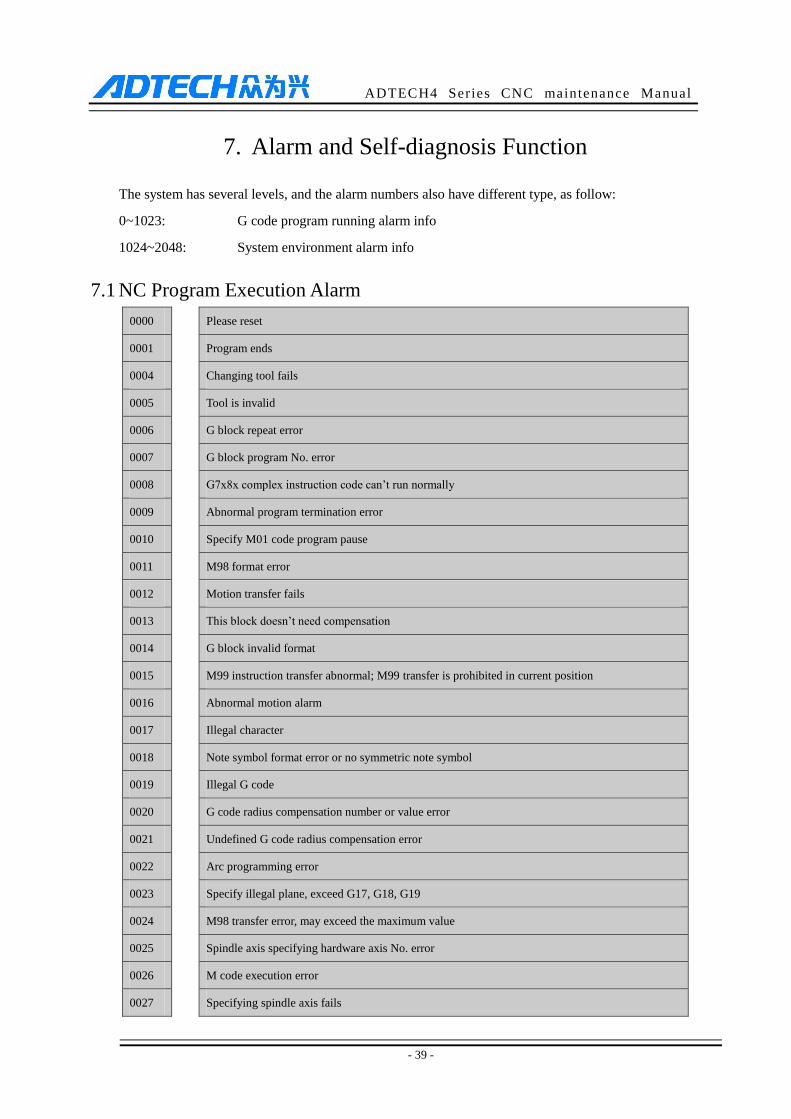
7.1 NC Program Execution Alarm
0000 : Please reset
0001 : Program ends
0004 : Changing tool fails
0005 : Tool is invalid
0006 : G block repeat error
0007 : G block program No. error
0008 : G7x8x complex instruction code can’t run normally
0009 : Abnormal program termination error
0010 : Specify M01 code program pause
0011 : M98 format error
0012 : Motion transfer fails
0013 : This block doesn’t need compensation
0014 : G block invalid format
0015 : M99 instruction transfer abnormal; M99 transfer is prohibited in current position
0016 : Abnormal motion alarm
0017 : Illegal character
0018 : Note symbol format error or no symmetric note symbol
0019 : Illegal G code
0020 : G code radius compensation number or value error
0021 : Undefined G code radius compensation error
0022 : Arc programming error
0023 : Specify illegal plane, exceed G17, G18, G19
0024 : M98 transfer error, may exceed the maximum value
0025 : Spindle axis specifying hardware axis No. error
0026 : M code execution error
0027 : Specifying spindle axis fails
ADTECH4 Series CNC maintenance Manual
- 40 -
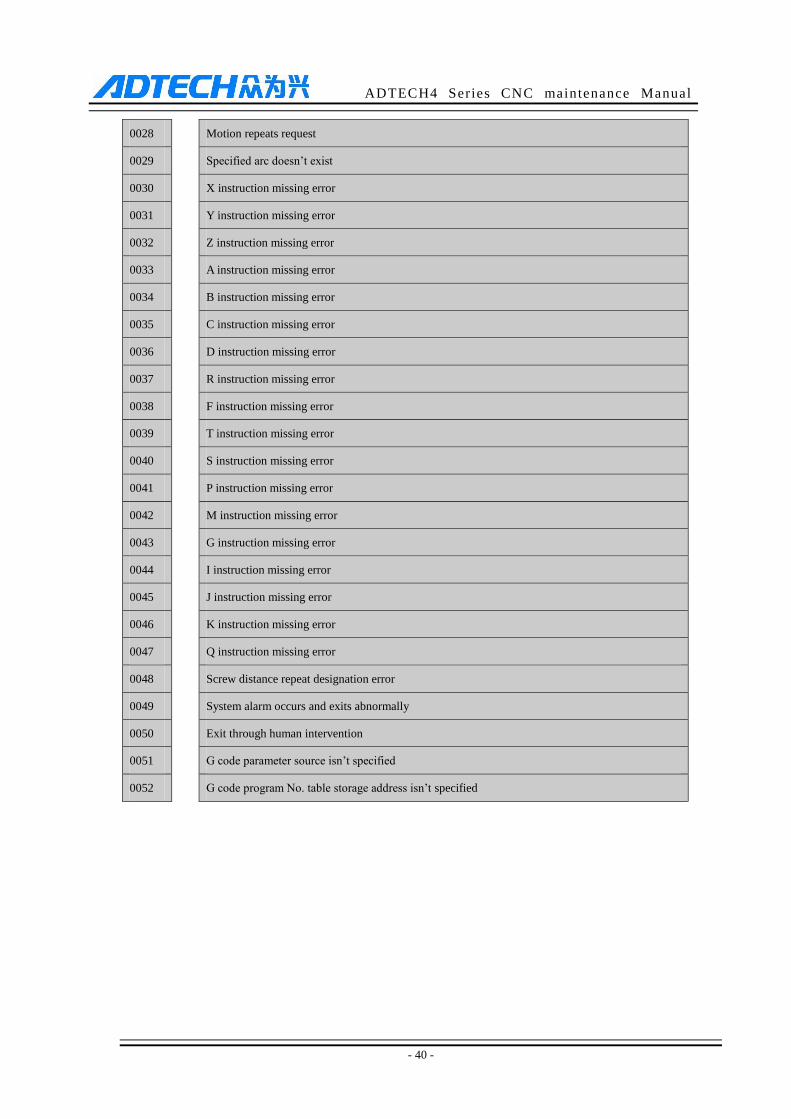
0028 : Motion repeats request
0029 : Specified arc doesn’t exist
0030 : X instruction missing error
0031 : Y instruction missing error
0032 : Z instruction missing error
0033 : A instruction missing error
0034 : B instruction missing error
0035 : C instruction missing error
0036 : D instruction missing error
0037 : R instruction missing error
0038 : F instruction missing error
0039 : T instruction missing error
0040 : S instruction missing error
0041 : P instruction missing error
0042 : M instruction missing error
0043 : G instruction missing error
0044 : I instruction missing error
0045 : J instruction missing error
0046 : K instruction missing error
0047 : Q instruction missing error
0048 : Screw distance repeat designation error
0049 : System alarm occurs and exits abnormally
0050 : Exit through human intervention
0051 : G code parameter source isn’t specified
0052 : G code program No. table storage address isn’t specified
ADTECH4 Series CNC maintenance Manual
- 41 -
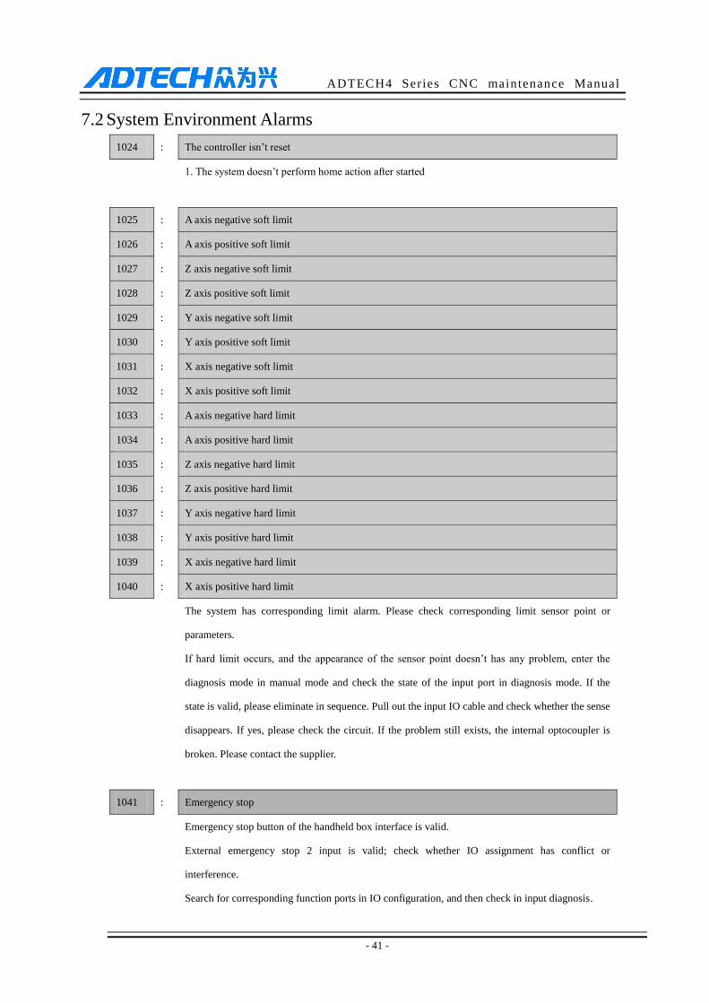
7.2 System Environment Alarms
1024 : The controller isn’t reset
1. The system doesn’t perform home action after started
1025 : A axis negative soft limit
1026 : A axis positive soft limit
1027 : Z axis negative soft limit
1028 : Z axis positive soft limit
1029 : Y axis negative soft limit
1030 : Y axis positive soft limit
1031 : X axis negative soft limit
1032 : X axis positive soft limit
1033 : A axis negative hard limit
1034 : A axis positive hard limit
1035 : Z axis negative hard limit
1036 : Z axis positive hard limit
1037 : Y axis negative hard limit
1038 : Y axis positive hard limit
1039 : X axis negative hard limit
1040 : X axis positive hard limit
The system has corresponding limit alarm. Please check corresponding limit sensor point or
parameters.
If hard limit occurs, and the appearance of the sensor point doesn’t has any problem, enter the
diagnosis mode in manual mode and check the state of the input port in diagnosis mode. If the
state is valid, please eliminate in sequence. Pull out the input IO cable and check whether the sense
disappears. If yes, please check the circuit. If the problem still exists, the internal optocoupler is
broken. Please contact the supplier.
1041 : Emergency stop
Emergency stop button of the handheld box interface is valid.
External emergency stop 2 input is valid; check whether IO assignment has conflict or
interference.
Search for corresponding function ports in IO configuration, and then check in input diagnosis.
ADTECH4 Series CNC maintenance Manual
- 42 -
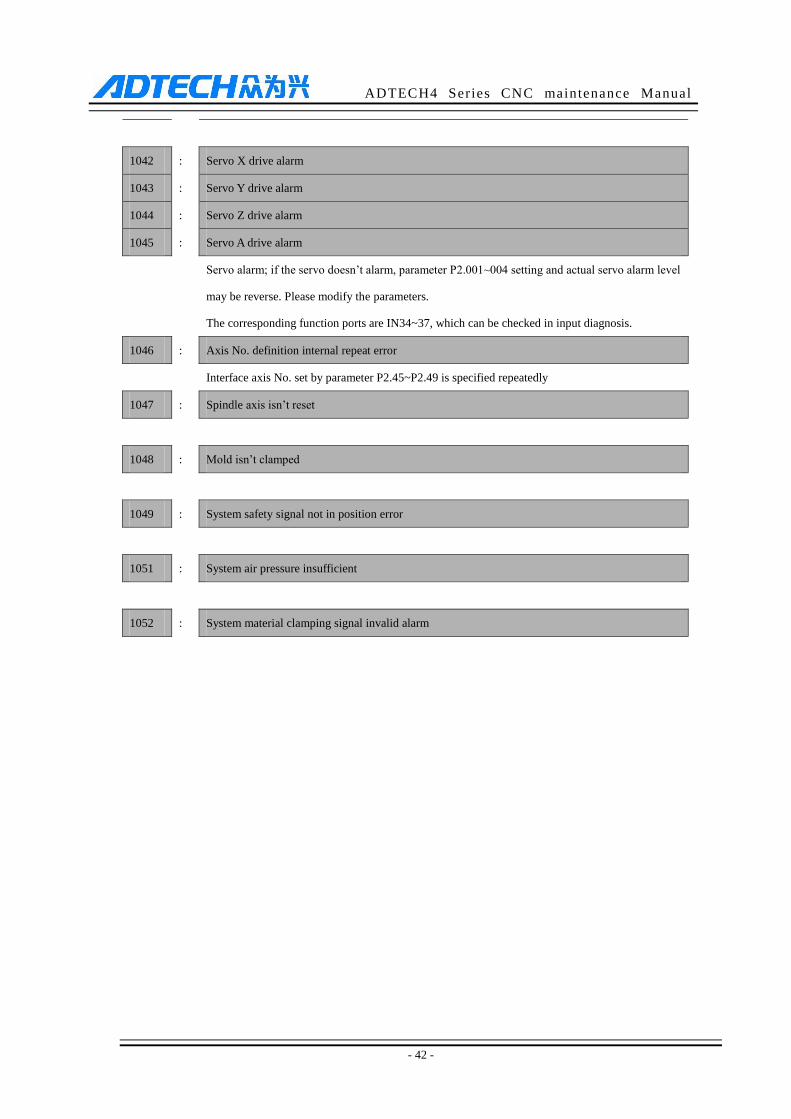
1042 : Servo X drive alarm
1043 : Servo Y drive alarm
1044 : Servo Z drive alarm
1045 : Servo A drive alarm
Servo alarm; if the servo doesn’t alarm, parameter P2.001~004 setting and actual servo alarm level
may be reverse. Please modify the parameters.
The corresponding function ports are IN34~37, which can be checked in input diagnosis.
1046 : Axis No. definition internal repeat error
Interface axis No. set by parameter P2.45~P2.49 is specified repeatedly
1047 : Spindle axis isn’t reset
1048 : Mold isn’t clamped
1049 : System safety signal not in position error
1051 : System air pressure insufficient
1052 : System material clamping signal invalid alarm
ADTECH4 Series CNC maintenance Manual
- 43 -
7.3 Alarm processing
If alarm occurs, please refer to the alarm code to confirm the failure reason.
When alarm occurs, if the system isn’t reset, the alarm will constantly prompt no matter whether the alarm
still exists, so as to avoid the conditions that false alarm causes system suspended, but can’t find the reason.
If the error is caused by data setting, modify the data, and then press [Reset] to clear the alarm info.
When alarm occurs, please remove the alarm reason. Please note that several alarms may occur at the same
time. Please refer to the alarm info in the Diagnosis menu for details. When the alarms are eliminated, please
press [Reset] to clear the alarm ring.
7.4 Self-diagnosis
CNC system sometimes stops even there is no alarm. The reason may be that the system is running
processes, and the self-diagnostic function is available for checking.
The self-diagnostic steps of the system are as follows:
(1) In the main menu, press [Diagnosis] to enter the diagnosis interface;
(2) Select [Input] to enter the input diagnosis interface, or select [Output] to enter the output diagnosis
interface;
(3) Output diagnosis: Press the direction keys select the output port, and press [EOB] to switch the output
level corresponding to the output port;
(4) Input diagnosis: When certain input signal is valid, the corresponding screen flashes.

ADTECH4 Series CNC maintenance Manual
- 44 -
8. Program Saving & Editing
8.1 Saving the Program in the Memory
8.1.1. Keypad Input (New Program)
Create new program in the memory with the keypad, and the step follows:
In the main menu, press [Edit] to enter program edit interface;
Press [File] to enter file operation interface;
Select [New] to create a new file;
Enter the file name and press [EOB] to confirm and create a new program in current directory in the
memory, and load into the system by default;
Select [Close] to exit [Edit] interface;
In edit mode, enter the program content;
After editing all programs, press [Reset] to save the edited programs into the system memory.
8.1.2. PC Serial Port Input
The step of transmitting files to controller through PC follows:
Set system baud rate and ID No.;
Connect to PC and run Adtech serial communication software;
Set the baud rate same as controller, and scan ID device;
Select the [Upload file to NC] button in the communication software;
Select CNC file in the popup dialog box and press [Open] button.
8.1.3. Copying Processing Files from USB Disk
The step of copying CNC processing file to system memory through USB disk follows:
In the main menu, press [Edit] to enter program edit interface;
Select [File] to enter file operation interface;
Select USB disk and press [EOB] to enter;
Move the cursor to select a CNC file and then select [Copy];
Return to the root directory, locate the PROG directory in disk D, enter the directory, and select [Paste] to
complete copying.
8.2 Reading Programs into Work Area
8.2.1. Reading Programs from Controller into Work Area
The step of loading files from system memory into work area follows:
Press [File] to enter file operation interface;

ADTECH4 Series CNC maintenance Manual
- 45 -
Select desired program, which is in PROG directory in disk D by default, press [EOB] to enter subdirectory,
or press [Cancel] to exit;
Move cursor to select desired program, press [EOB] to confirm and load the program.
8.2.2. Reading Programs from USB Disk into Work Area
The step of loading files from USB disk into work area follows:
Insert the USB disk;
Press [File] to enter file operation interface;
Select USB disk, move cursor to select a file in the disk, and press [EOB] to load the file.
8.3 Editing & Modifying Programs
The program in CNC memory can be edited with NC keypad. In the main menu, press [Edit] to enter
program edit interface and edit the program in current work area (for loading program into work area,
refer to 8.2). The edit mode is similar to notepad in Windows. Move the cursor directly to locate, press
keys to enter, press [EOB] to change line, and press [Delete] to delete the character where the cursor
locates, and press [Cancel] to delete previous character.
Caution
After all operations, press Reset to save the files, and the functions base on edit mode;
CNC46XX uses new file mapping technology, and allows loading processing files that exceed its memory.
Therefore, to ensure the system efficiency, you can only search and process, but can’t edit the processing files
that exceed 2M.
8.4 Deleting Files
8.4.1. Deleting Files in Memory
Follow the step below to delete the programs in system memory:
Press [File] to enter file operation interface;
Follow the prompt on the interface , select the file and press [Delete] to confirm and delete the file.
Caution
If the file has been loaded into work area, you need to restart the system to delete the program, or else the
system will report error.
The programs loaded into the work area can’t be deleted, or else the system will report error.
ADTECH4 Series CNC maintenance Manual
- 46 -
9. Main Interfaces of the System
9.1 Position Interface
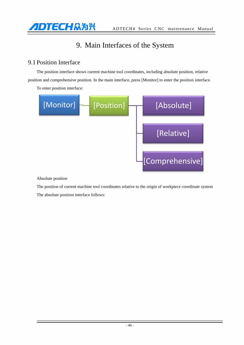
The position interface shows current machine tool coordinates, including absolute position, relative
position and comprehensive position. In the main interface, press [Monitor] to enter the position interface.
To enter position interface:
Absolute position
The position of current machine tool coordinates relative to the origin of workpiece coordinate system
The absolute position interface follows:
[Monitor] [Position] [Absolute]
[Relative]
[Comprehensive]
ADTECH4 Series CNC maintenance Manual
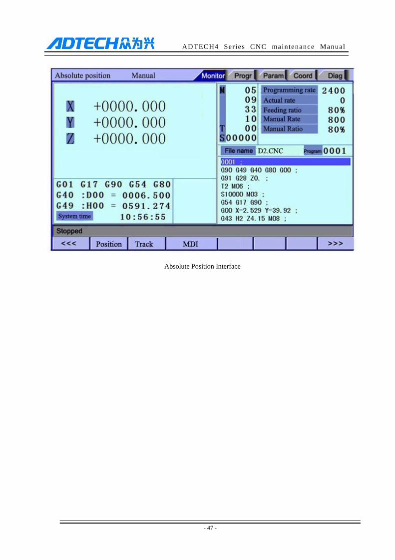
- 47 -
Absolute Position Interface
ADTECH4 Series CNC maintenance Manual
- 48 -
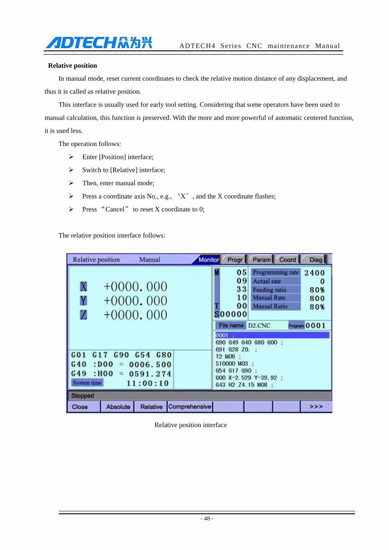
Relative position
In manual mode, reset current coordinates to check the relative motion distance of any displacement, and
thus it is called as relative position.
This interface is usually used for early tool setting. Considering that some operators have been used to
manual calculation, this function is preserved. With the more and more powerful of automatic centered function,
it is used less.
The operation follows:
Enter [Position] interface;
Switch to [Relative] interface;
Then, enter manual mode;
Press a coordinate axis No., e.g., ‘X’, and the X coordinate flashes;
Press “Cancel” to reset X coordinate to 0;
The relative position interface follows:
Relative position interface
ADTECH4 Series CNC maintenance Manual
- 49 -
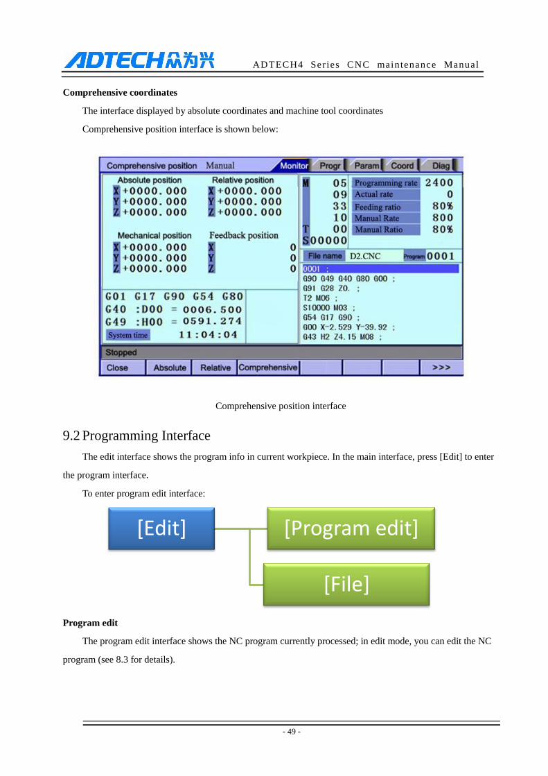
Comprehensive coordinates
The interface displayed by absolute coordinates and machine tool coordinates
Comprehensive position interface is shown below:
Comprehensive position interface
9.2 Programming Interface
The edit interface shows the program info in current workpiece. In the main interface, press [Edit] to enter
the program interface.
To enter program edit interface:
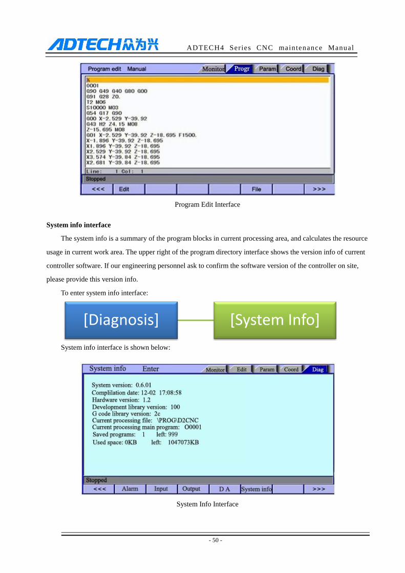
Program edit
The program edit interface shows the NC program currently processed; in edit mode, you can edit the NC
program (see 8.3 for details).
[Edit] [Program edit]
[File]
ADTECH4 Series CNC maintenance Manual
- 50 -
Program Edit Interface
System info interface
The system info is a summary of the program blocks in current processing area, and calculates the resource
usage in current work area. The upper right of the program directory interface shows the version info of current
controller software. If our engineering personnel ask to confirm the software version of the controller on site,
please provide this version info.
To enter system info interface:
System info interface is shown below:
System Info Interface
[Diagnosis] [System Info]
ADTECH4 Series CNC maintenance Manual
- 51 -
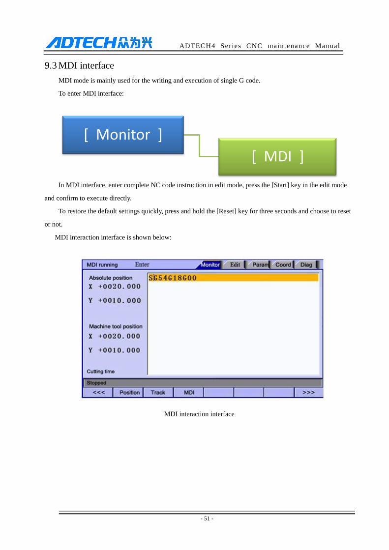
9.3 MDI interface
MDI mode is mainly used for the writing and execution of single G code.
To enter MDI interface:
In MDI interface, enter complete NC code instruction in edit mode, press the [Start] key in the edit mode
and confirm to execute directly.
To restore the default settings quickly, press and hold the [Reset] key for three seconds and choose to reset
or not.
MDI interaction interface is shown below:
MDI interaction interface
[ Monitor ]
[ MDI ]
ADTECH4 Series CNC maintenance Manual
- 52 -
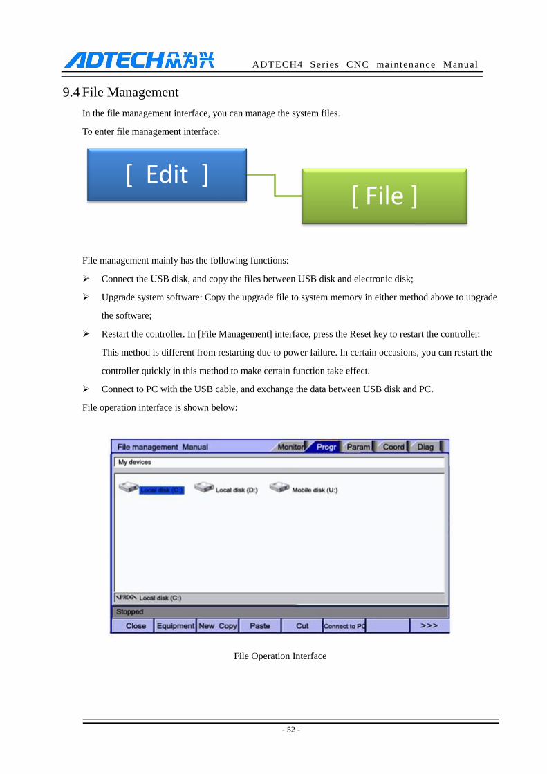
9.4 File Management
In the file management interface, you can manage the system files.
To enter file management interface:
File management mainly has the following functions:
Connect the USB disk, and copy the files between USB disk and electronic disk;
Upgrade system software: Copy the upgrade file to system memory in either method above to upgrade
the software;
Restart the controller. In [File Management] interface, press the Reset key to restart the controller.
This method is different from restarting due to power failure. In certain occasions, you can restart the
controller quickly in this method to make certain function take effect.
Connect to PC with the USB cable, and exchange the data between USB disk and PC.
File operation interface is shown below:
File Operation Interface
[ Edit ] [ File ]
ADTECH4 Series CNC maintenance Manual
- 53 -
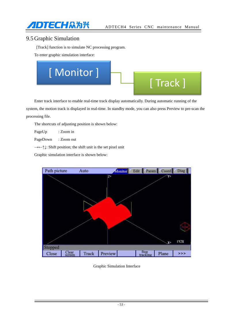
9.5 Graphic Simulation
[Track] function is to simulate NC processing program.
To enter graphic simulation interface:
Enter track interface to enable real-time track display automatically. During automatic running of the
system, the motion track is displayed in real-time. In standby mode, you can also press Preview to pre-scan the
processing file.
The shortcuts of adjusting position is shown below:
PageUp : Zoom in
PageDown : Zoom out
→←↑↓: Shift position; the shift unit is the set pixel unit
Graphic simulation interface is shown below:
Graphic Simulation Interface
[ Monitor ] [ Track ]
ADTECH4 Series CNC maintenance Manual
- 54 -
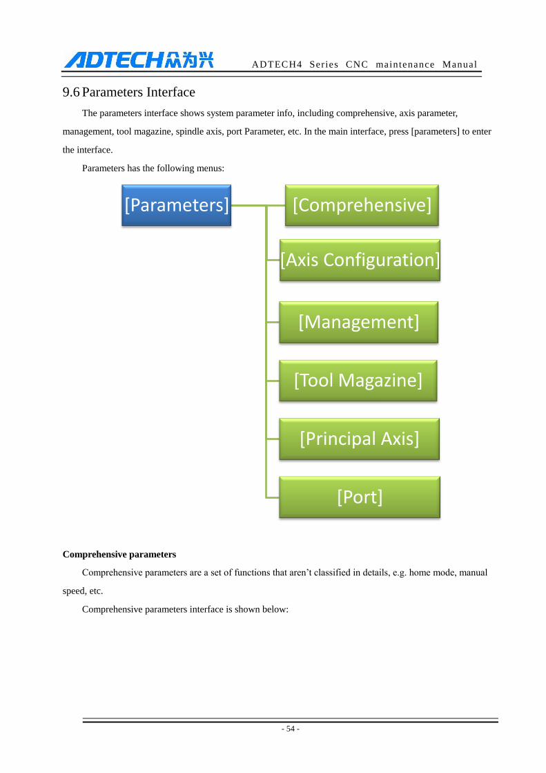
9.6 Parameters Interface
The parameters interface shows system parameter info, including comprehensive, axis parameter,
management, tool magazine, spindle axis, port Parameter, etc. In the main interface, press [parameters] to enter
the interface.
Parameters has the following menus:
Comprehensive parameters
Comprehensive parameters are a set of functions that aren’t classified in details, e.g. home mode, manual
speed, etc.
Comprehensive parameters interface is shown below:
[Parameters] [Comprehensive]
[Axis Configuration]
[Management]
[Tool Magazine]
[Principal Axis]
[Port]

ADTECH4 Series CNC maintenance Manual
- 55 -
Comprehensive Parameter Interface
Axis parameters
Axis parameters are parameter set of interface characteristics of control position axis. Please refer to the
parameter description for details.
Axis parameters interface is shown below:
Axis Parameters Interface
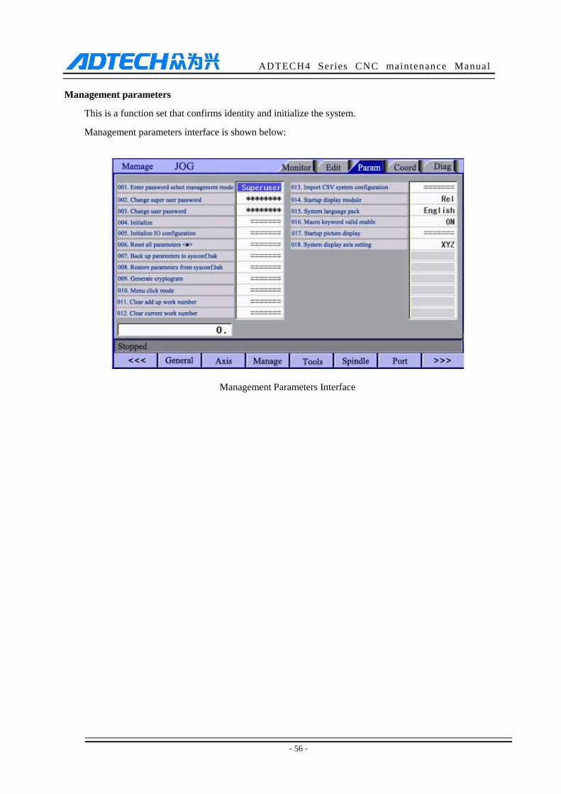
ADTECH4 Series CNC maintenance Manual
- 56 -
Management parameters
This is a function set that confirms identity and initialize the system.
Management parameters interface is shown below:
Management Parameters Interface
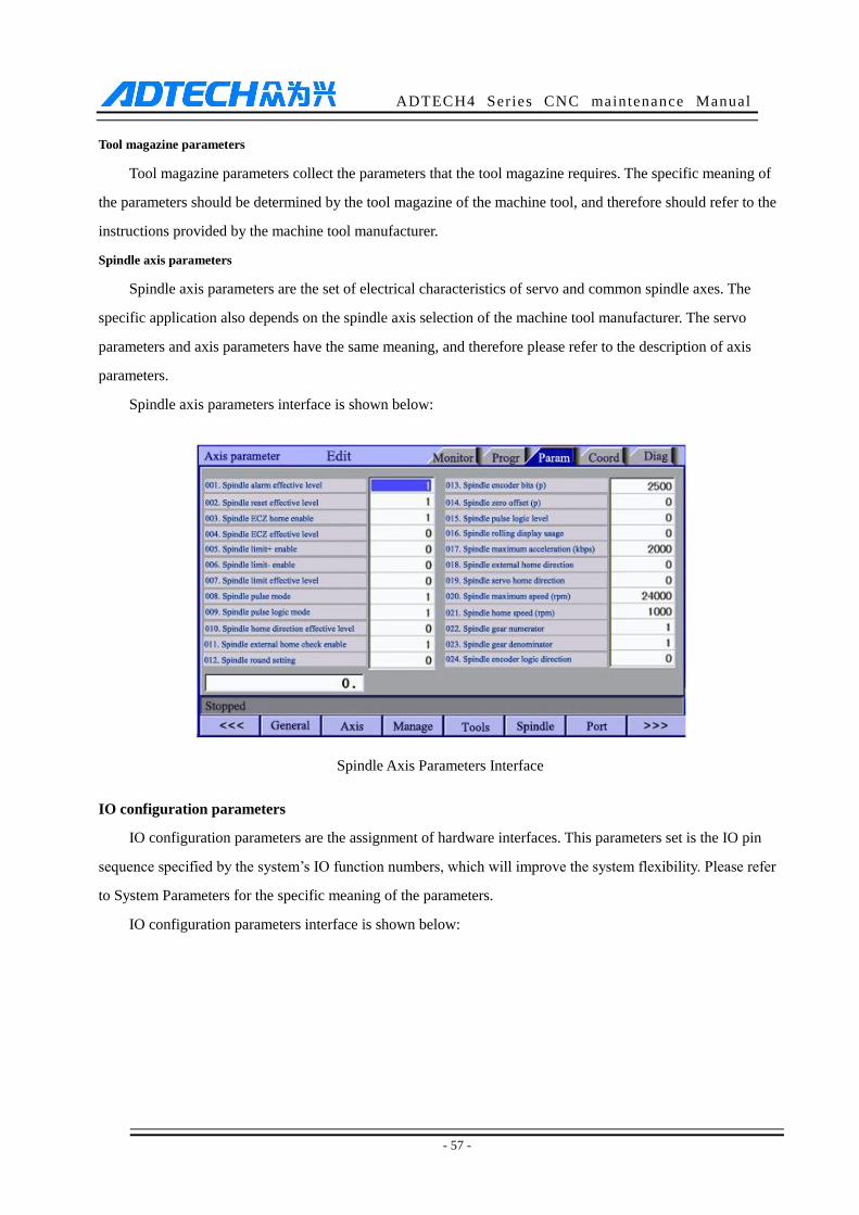
ADTECH4 Series CNC maintenance Manual
- 57 -
Tool magazine parameters
Tool magazine parameters collect the parameters that the tool magazine requires. The specific meaning of
the parameters should be determined by the tool magazine of the machine tool, and therefore should refer to the
instructions provided by the machine tool manufacturer.
Spindle axis parameters
Spindle axis parameters are the set of electrical characteristics of servo and common spindle axes. The
specific application also depends on the spindle axis selection of the machine tool manufacturer. The servo
parameters and axis parameters have the same meaning, and therefore please refer to the description of axis
parameters.
Spindle axis parameters interface is shown below:
Spindle Axis Parameters Interface
IO configuration parameters
IO configuration parameters are the assignment of hardware interfaces. This parameters set is the IO pin
sequence specified by the system’s IO function numbers, which will improve the system flexibility. Please refer
to System Parameters for the specific meaning of the parameters.
IO configuration parameters interface is shown below:
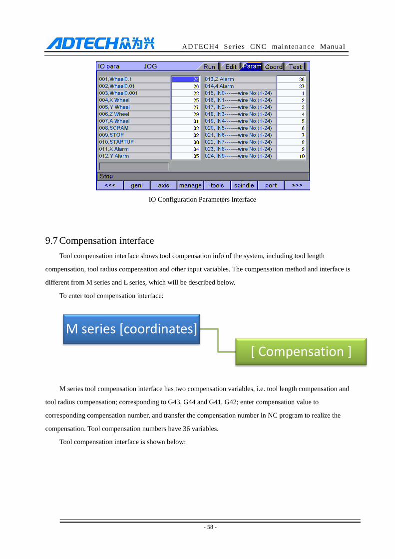
ADTECH4 Series CNC maintenance Manual
- 58 -
IO Configuration Parameters Interface
9.7 Compensation interface
Tool compensation interface shows tool compensation info of the system, including tool length
compensation, tool radius compensation and other input variables. The compensation method and interface is
different from M series and L series, which will be described below.
To enter tool compensation interface:
M series tool compensation interface has two compensation variables, i.e. tool length compensation and
tool radius compensation; corresponding to G43, G44 and G41, G42; enter compensation value to
corresponding compensation number, and transfer the compensation number in NC program to realize the
compensation. Tool compensation numbers have 36 variables.
Tool compensation interface is shown below:
M series [coordinates]
[ Compensation ]
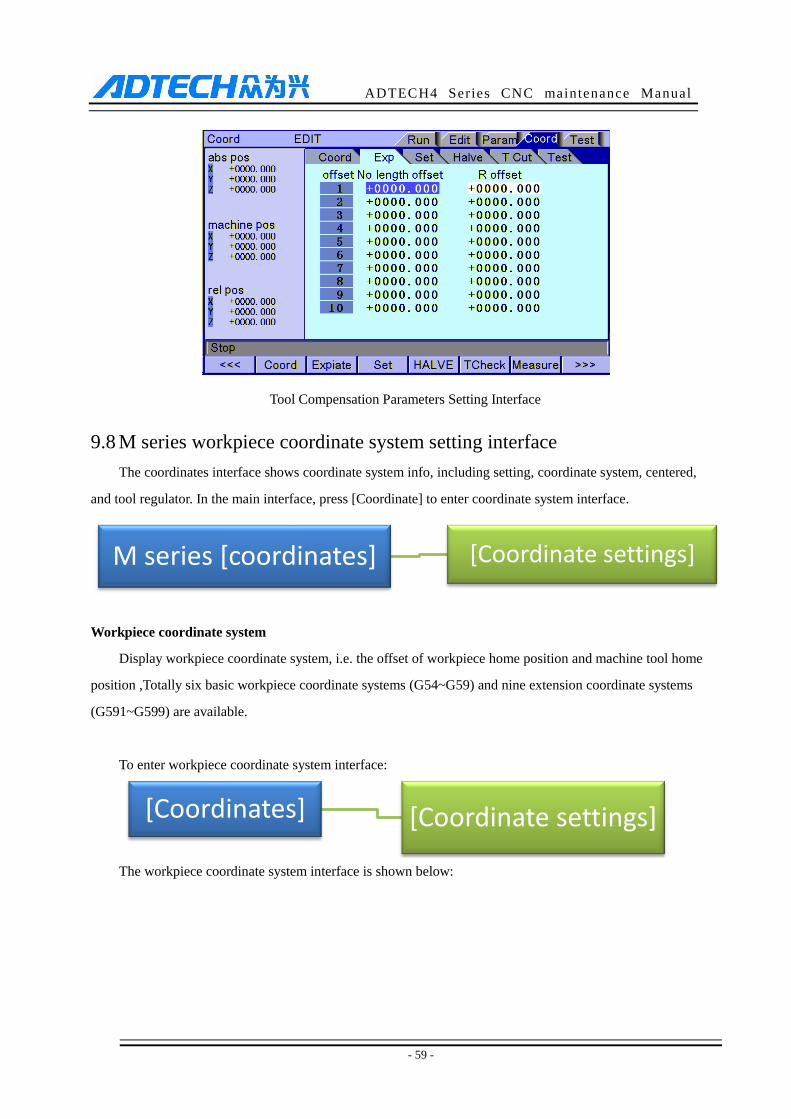
ADTECH4 Series CNC maintenance Manual
- 59 -
Tool Compensation Parameters Setting Interface
9.8 M series workpiece coordinate system setting interface
The coordinates interface shows coordinate system info, including setting, coordinate system, centered,
and tool regulator. In the main interface, press [Coordinate] to enter coordinate system interface.
Workpiece coordinate system
Display workpiece coordinate system, i.e. the offset of workpiece home position and machine tool home
position ,Totally six basic workpiece coordinate systems (G54~G59) and nine extension coordinate systems
(G591~G599) are available.
To enter workpiece coordinate system interface:
The workpiece coordinate system interface is shown below:
M series [coordinates] [Coordinate settings]
[Coordinates] [Coordinate settings]

ADTECH4 Series CNC maintenance Manual
- 60 -
Workpiece Coordinate System Setting Interface
Coordinate system auxiliary parameters setting interface
The auxiliary parameters for workpiece coordinate system, including origin offset and tool setting
parameters of automatic tool regulator.
To enter coordinate system auxiliary parameter setting interface:
The detailed auxiliary parameters are described in the table below:
1 X coordinates offset
2 Y coordinates offset
3 Z coordinates offset
4 A coordinates offset
5 X coordinates of tool regulator
6 Y coordinates of tool regulator
7 Z coordinates of tool regulator
8 Axis selection symbol of tool regulator
9 Effective voltage level of tool regulator
10 Set tool automatically after changing
11 Tool regulator machine tool X limit
12 Tool regulator machine tool Y limit
13 Tool regulator machine tool Z limit
14 Tool regulator X search direction
[Coordinates] [Coordinate parameters]

ADTECH4 Series CNC maintenance Manual
- 61 -
15 Tool regulator Y search direction
16 Tool regulator Z search direction
17 Tool regulator limit effective signal
18 Add offset to coordinates automatically
(1) Origin offset
The origin offset is added to current machine tool coordinates when setting the coordinate system; this
parameters setting is available in next tool setting;
The application of this parameters is for the processing of certain parts that require several working
procedures. The first processing procedure may damage the tool setting position of the workpiece, and
the next procedure can’t locate the proper tool setting position. Therefore, a reference tool setting point
is required, and the offset from reference point to actual tool setting position can be set to this parameter.
No matter tool setting in which procedure, you only need to set to this reference point and it is same
like setting to home position of the workpiece.
(2) Tool regulator coordinates, effective signal, automatic tool setting, machine tool Z negative limit of tool
regulator:
The X, Y coordinates are the mechanical coordinates of the tool regulator on machine tool; the tool
regulator can position automatically only when the coordinate is set properly.
Effective voltage level of tool regulator is to set the signal interface level of the tool regulator, which
should be set according to the actual interface of the tool regulator.
Automatic tool setting after changing is that the tool regulator function executes automatically after tool
changing instruction is returned successfully to improve the processing efficiency.
Z negative limit is used to prevent crash caused by not in place of Z axis error checking. Once negative
limit alarm occurs, the tool regulator stops working immediately. If the system is in processing state, the
system will send abnormal alarm; during separate setting of the tool regulator, the alarm won’t occur.

ADTECH4 Series CNC maintenance Manual
- 62 -
9.9 Controller Diagnosis Interface (Diagnosis)
The diagnosis interface is used to display the hardware interfaces and system info, including alarm, input,
output, DA diagnosis; press [Diagnosis] to enter the diagnosis interface.
The diagnosis interface follows:
Alarm interface
Display the alarm of the system after power on, including 15 alarm records.
IO diagnosis interface
IO diagnosis allows entering at any moment. You can check current IO state of the system. In manual mode,
press the direction keys to select corresponding IO, and press EOB to control the output manually.
DA diagnosis interface
Correct the output voltage of two lines DA voltage module for testing; press the direction keys to output
corresponding voltage directly, input the actually measured voltage to corresponding gear position; when
transferring control instructions of spindle axis, the system will correct according to correction value.
System info
The system info shows basic information of current system, and is used to mark current software version,
hardware version, upgrade info, etc. In this interface, you can follow the prompt to perform operations.
[ Diagnosis ] [ Alarm info ]
[ Input diagnosis ]
[ Output diagnosis ]
[ DA diagnosis ]
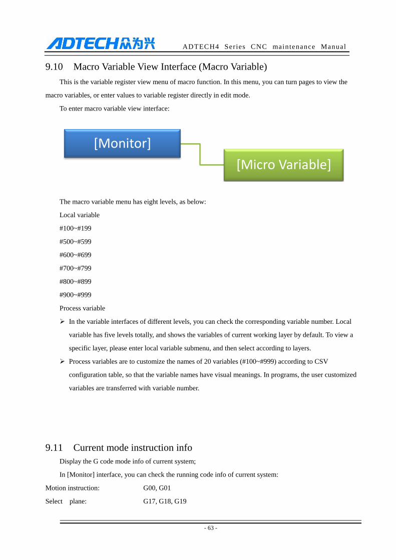
ADTECH4 Series CNC maintenance Manual
- 63 -
9.10 Macro Variable View Interface (Macro Variable)
This is the variable register view menu of macro function. In this menu, you can turn pages to view the
macro variables, or enter values to variable register directly in edit mode.
To enter macro variable view interface:
The macro variable menu has eight levels, as below:
Local variable
#100~#199
#500~#599
#600~#699
#700~#799
#800~#899
#900~#999
Process variable
In the variable interfaces of different levels, you can check the corresponding variable number. Local
variable has five levels totally, and shows the variables of current working layer by default. To view a
specific layer, please enter local variable submenu, and then select according to layers.
Process variables are to customize the names of 20 variables (#100~#999) according to CSV
configuration table, so that the variable names have visual meanings. In programs, the user customized
variables are transferred with variable number.
9.11 Current mode instruction info
Display the G code mode info of current system;
In [Monitor] interface, you can check the running code info of current system:
Motion instruction: G00, G01
Select plane: G17, G18, G19
[Monitor]
[Micro Variable]
ADTECH4 Series CNC maintenance Manual
- 64 -
Coordinate logic: G90, G91
Workpiece coordinate system: G54, G59, G591…G599
Radius compensation: G40, G41, G42
Length compensation: G43, G44, G49
Compound instruction retracting plane: G98, G99
Spindle axis rotation: S
Tool No.: T
ADTECH4 Series CNC maintenance Manual
- 65 -
10. System Maintenance
10.1 Restart
(1) In the main menu, press [Edit] to enter the program interface;
(2) Press [File] to enter the file interface;
(3) Press [Reset] and the system asks whether restart or not;
(4) Press [OK] to restart the system.
10.2 System Upgrade
The step of copying upgrade program with USB disk as follows:
(1) In the main menu, press [Edit] to enter the program interface;
(2) Press [File] to enter the file management interface;
(3) Insert the USB flash drive, open the disk in the root directory and enter the USB drive directory if it is
read successfully;
(4) Move cursor to the upgrade file ADTROM.BIN, select [Copy], enter disk D, and paste in directory
ADT.
(5) Select the second upgrade file NC_RES.NC; skip this step if the file doesn’t exist. Also select Copy,
enter disk D, and paste in directory ADT.
(6) After upgrading, enter BIOS, select USB in [Boot-up mode], and restart the system to take effect.
(7) Enter System Info in Diagnosis menu to view the system version and compilation date, and check
whether the upgrade is successful.
10.3 Reset
(1) Select the edit mode;
(2) In the main menu, press [Parameters] to enter the parameters interface;
(3) Press [Management] key to enter management parameters interface;
(4) Move cursor to “006 Reset all parameters”;
(5) Press [EOB], the system confirms, restores the default parameters and restarts automatically.
10.4 Parameters Backup & Restore
(1) Select the edit mode;
ADTECH4 Series CNC maintenance Manual
- 66 -
(2) In the main menu, press [Parameters] key to enter the parameters interface;
(3) Press the [Management] key to enter management parameters interface;
(4) Move the cursor to 007 or 008 and select appropriate menu;
(5) Press the [EOB] key, the system confirms and performs backup and restore operation;
(6) The backup operation will generate the SYSCONF.BAK file in the root directory of disk D. Please save
this file for backup in the future.
(7) For restore operation, also save the SYSCONF.BAK file in the root directory of disk D. The system will
recognize this file automatically in the process of restoring.
10.5 Entering BISO Interface
(1) If the system can’t be started due to irreversible error, you can enter the BIOS to upgrade and maintain
the program;
(2) Enter the BIOS after the controller powers on and before the program is started, press the [Cancel]
button to enter a blue background successfully; if the BIOS has password, it will pop up a prompt, and
type the valid password to enter the BIOS
(3) Enter the BIOS to perform the maintenance: Format C, D disk, copy USB disk files and upgrade;

ADTECH4 Series CNC maintenance Manual
- 67 -
11. System Parameters
According to occasions and functions, the parameters contain comprehensive parameters, IO configuration
parameters, management parameters and coordinate setting parameters.
Comprehensive parameters are complete, and contain basic operation and usage settings of the
controller, including spindle axis, hand wheel, home, tool magazine, etc.;
IO configuration parameters are mainly used for machine installation and test, adapting to the interface
characteristics of machine tool and motor drive;
Coordinate setting parameters are tool setting configuration in [Coordinate] interface;
(1) It is required to confirm user identity to modify the parameter table. The controller has two levels of
user authority, which are super user and operator; super user can modify all parameters and user passwords;
while operator only can operate the parameters that require modification, and modify the operator password; in
P3.1 of management parameters, the system enters the corresponding mode automatically according to the
entered password.
(2) According to the application, the parameters will take effect immediately or after restarted; the
parameters that require restart are marked with <●>.
(3) Certain parameters are set in binary system (parameters descriptor has bit symbol); the conversion
between binary system and decimal system follows:
Bit0: Set to 1 to correspond to decimal 1;
Bit1: Set to 1 to correspond to decimal 2;
Bit2: Set to 1 to correspond to decimal 4;
Bit3: Set to 1 to correspond to decimal 8;
Bit4: Set to 1 to correspond to decimal 16;
Bit5: Set to 1 to correspond to decimal 32;
Bit6: Set to 1 to correspond to decimal 64;
Bit7: Set to 1 to correspond to decimal 128;
For more bits, multiply the decimal system corresponding to binary system of previous position by 2. If
only the corresponding bit is 1, accumulate the numbers of corresponding decimal system according to the
comparison table to get the setting value.
For example: set Bit0, Bit1 and Bit5 to 1, and the parameter will be 1+2+32=35.

ADTECH4 Series CNC maintenance Manual
- 68 -
11.1 Parameter Index List
Parameter type S/N Description Effective
mode
Default
value
Pag
e
General parameter
(P1.) 001 Feeding speed Instant
General parameter
(P1.) 002 Initial feeding speed Instant
General parameter
(P1.) 003 Feeding acceleration Instant
General parameter
(P1.) 004 Home mode Instant
General parameter
(P1.) 005 IO filter level (1~8) Instant
General parameter
(P1.) 006 Select communication mode Restart
General parameter
(P1.) 007 Maximum feeding speed Instant
General parameter
(P1.) 008 Maximum hand wheel speed Instant
General parameter
(P1.) 009 Hand wheel response factor Instant
General parameter
(P1.) 010 M code waiting time (ms) Instant
General parameter
(P1.) 011 Line number increment Instant
General parameter
(P1.) 012 System baud rate Restart
General parameter
(P1.) 013 Controller ID
Restart
General parameter
(P1.) 014 Arc interpolation feed rate
Instant
General parameter
(P1.) 015
G73(M) circulating tool retraction
amount (mm)
Instant

ADTECH4 Series CNC maintenance Manual
- 69 -
Parameter type S/N Description Effective
mode
Default
value
Pag
e
General parameter
(P1.) 016
G83(M) circulating tool retraction
amount (mm)
Instant
General parameter
(P1.) 017 Arc interpolation processing mode
Instant
General parameter
(P1.) 018
Speed optimization constraint
mode
Instant
General parameter
(P1.) 019
Code pretreatment processing
mode
Instant
General parameter
(P1.) 020 CNC file scan flag
Instant
General parameter
(P1.) 021
Variable frequency analog control
mode
Instant
General parameter
(P1.) 022
Lubricant pressure schedule open
(min)
Instant
General parameter
(P1.) 023
Lubricant pressure holding time
(sec)
Instant
General parameter
(P1.) 024 Lubricant control frequency (Hz)
Instant
General parameter
(P1.) 025
Automatic home mode
configuration (bit)
Instant
General parameter
(P1.) 026 Arc Acc.for Radii
Instant
General parameter
(P1.) 027 Arc Acc.for Speed
Instant
General parameter
(P1.) 028 Pretreatment buffer sections
Instant
General parameter
(P1.) 029
Interpolation acceleration speed
mode
Instant
General parameter
(P1.) 030 'S'Speed Acceleration
Instant
General parameter 031 Home test enable after alarm Instant
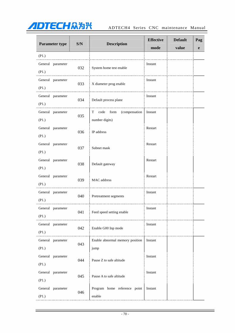
ADTECH4 Series CNC maintenance Manual
- 70 -
Parameter type S/N Description Effective
mode
Default
value
Pag
e
(P1.)
General parameter
(P1.) 032 System home test enable
Instant
General parameter
(P1.) 033 X diameter prog enable
Instant
General parameter
(P1.) 034 Default process plane
Instant
General parameter
(P1.) 035
T code form (compensation
number digits)
Instant
General parameter
(P1.) 036 IP address
Restart
General parameter
(P1.) 037 Subnet mask
Restart
General parameter
(P1.) 038 Default gateway
Restart
General parameter
(P1.) 039 MAC address
Restart
General parameter
(P1.) 040 Pretreatment segments
Instant
General parameter
(P1.) 041 Feed speed setting enable
Instant
General parameter
(P1.) 042 Enable G00 Inp mode
Instant
General parameter
(P1.) 043
Enable abnormal memory position
jump
Instant
General parameter
(P1.) 044 Pause Z to safe altitude
Instant
General parameter
(P1.) 045 Pause A to safe altitude
Instant
General parameter
(P1.) 046
Program home reference point
enable
Instant
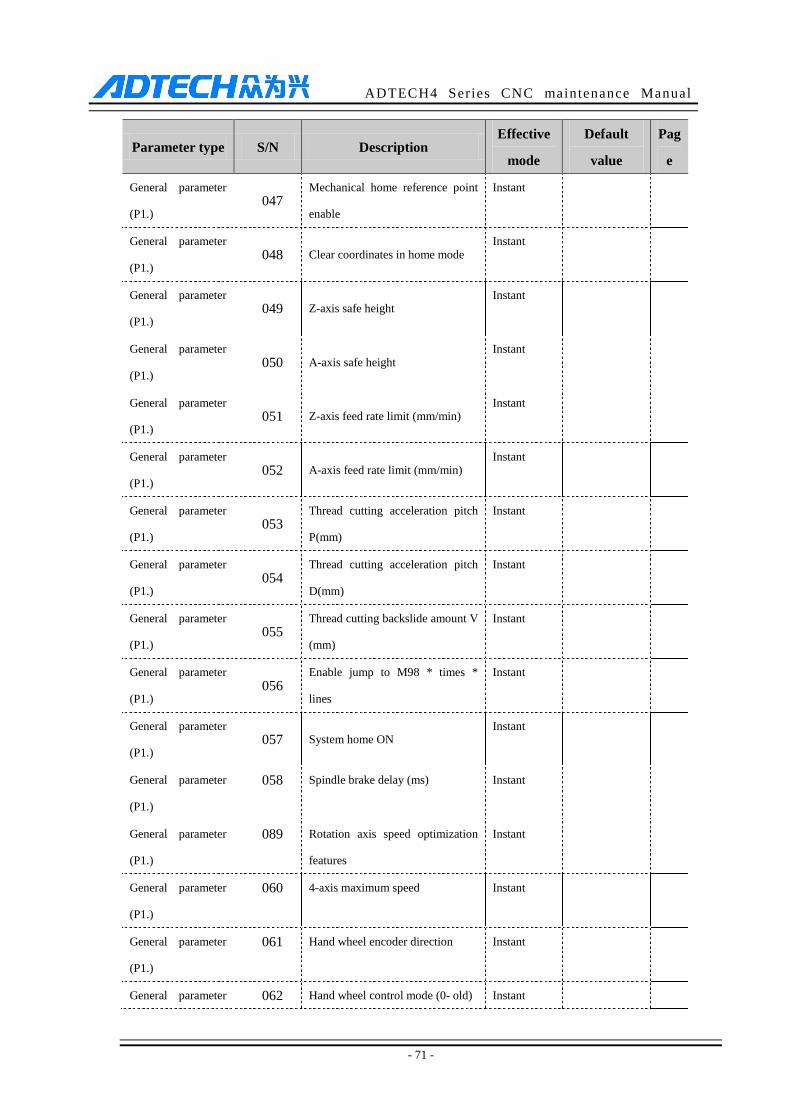
ADTECH4 Series CNC maintenance Manual
- 71 -
Parameter type S/N Description Effective
mode
Default
value
Pag
e
General parameter
(P1.) 047
Mechanical home reference point
enable
Instant
General parameter
(P1.) 048 Clear coordinates in home mode
Instant
General parameter
(P1.) 049 Z-axis safe height
Instant
General parameter
(P1.) 050 A-axis safe height
Instant
General parameter
(P1.) 051 Z-axis feed rate limit (mm/min)
Instant
General parameter
(P1.) 052 A-axis feed rate limit (mm/min)
Instant
General parameter
(P1.) 053
Thread cutting acceleration pitch
P(mm)
Instant
General parameter
(P1.) 054
Thread cutting acceleration pitch
D(mm)
Instant
General parameter
(P1.) 055
Thread cutting backslide amount V
(mm)
Instant
General parameter
(P1.) 056
Enable jump to M98 * times *
lines
Instant
General parameter
(P1.) 057 System home ON
Instant
General parameter
(P1.)
058 Spindle brake delay (ms) Instant
General parameter
(P1.)
089 Rotation axis speed optimization
features
Instant
General parameter
(P1.)
060 4-axis maximum speed Instant
General parameter
(P1.)
061 Hand wheel encoder direction Instant
General parameter 062 Hand wheel control mode (0- old) Instant
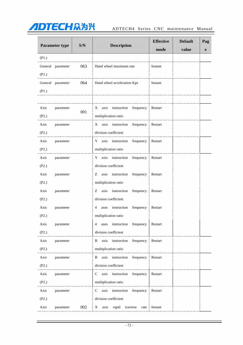
ADTECH4 Series CNC maintenance Manual
- 72 -
Parameter type S/N Description Effective
mode
Default
value
Pag
e
(P1.)
General parameter
(P1.)
063 Hand wheel maximum rate Instant
General parameter
(P1.)
064 Hand wheel acceleration Kps Instant
Axis parameter
(P2.) 001
X axis instruction frequency
multiplication ratio
Restart
Axis parameter
(P2.)
X axis instruction frequency
division coefficient
Restart
Axis parameter
(P2.)
Y axis instruction frequency
multiplication ratio
Restart
Axis parameter
(P2.)
Y axis instruction frequency
division coefficient
Restart
Axis parameter
(P2.)
Z axis instruction frequency
multiplication ratio
Restart
Axis parameter
(P2.)
Z axis instruction frequency
division coefficient
Restart
Axis parameter
(P2.)
4 axes instruction frequency
multiplication ratio
Restart
Axis parameter
(P2.)
4 axes instruction frequency
division coefficient
Restart
Axis parameter
(P2.)
B axis instruction frequency
multiplication ratio
Restart
Axis parameter
(P2.)
B axis instruction frequency
division coefficient
Restart
Axis parameter
(P2.)
C axis instruction frequency
multiplication ratio
Restart
Axis parameter
(P2.)
C axis instruction frequency
division coefficient
Restart
Axis parameter 002 X axis rapid traverse rate Instant
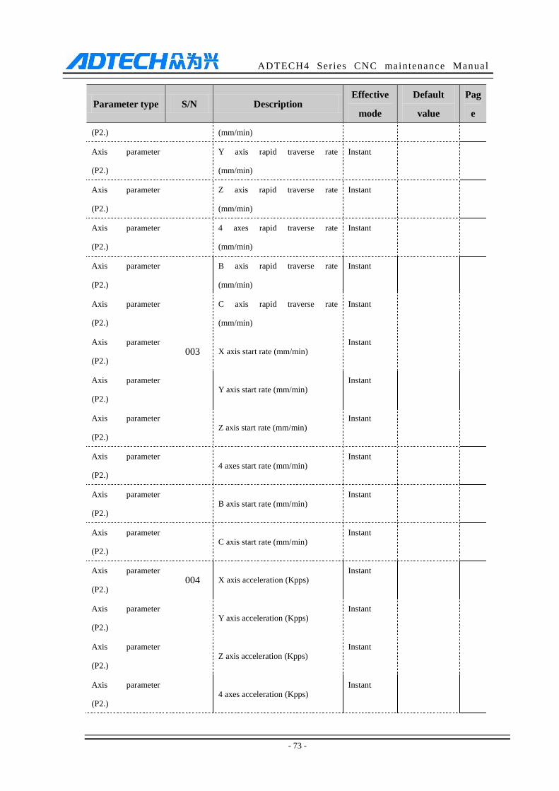
ADTECH4 Series CNC maintenance Manual
- 73 -
Parameter type S/N Description Effective
mode
Default
value
Pag
e
(P2.) (mm/min)
Axis parameter
(P2.)
Y axis rapid traverse rate
(mm/min)
Instant
Axis parameter
(P2.)
Z axis rapid traverse rate
(mm/min)
Instant
Axis parameter
(P2.)
4 axes rapid traverse rate
(mm/min)
Instant
Axis parameter
(P2.)
B axis rapid traverse rate
(mm/min)
Instant
Axis parameter
(P2.)
C axis rapid traverse rate
(mm/min)
Instant
Axis parameter
(P2.) 003 X axis start rate (mm/min)
Instant
Axis parameter
(P2.) Y axis start rate (mm/min)
Instant
Axis parameter
(P2.) Z axis start rate (mm/min)
Instant
Axis parameter
(P2.) 4 axes start rate (mm/min)
Instant
Axis parameter
(P2.) B axis start rate (mm/min)
Instant
Axis parameter
(P2.) C axis start rate (mm/min)
Instant
Axis parameter
(P2.) 004 X axis acceleration (Kpps)
Instant
Axis parameter
(P2.) Y axis acceleration (Kpps)
Instant
Axis parameter
(P2.) Z axis acceleration (Kpps)
Instant
Axis parameter
(P2.) 4 axes acceleration (Kpps)
Instant
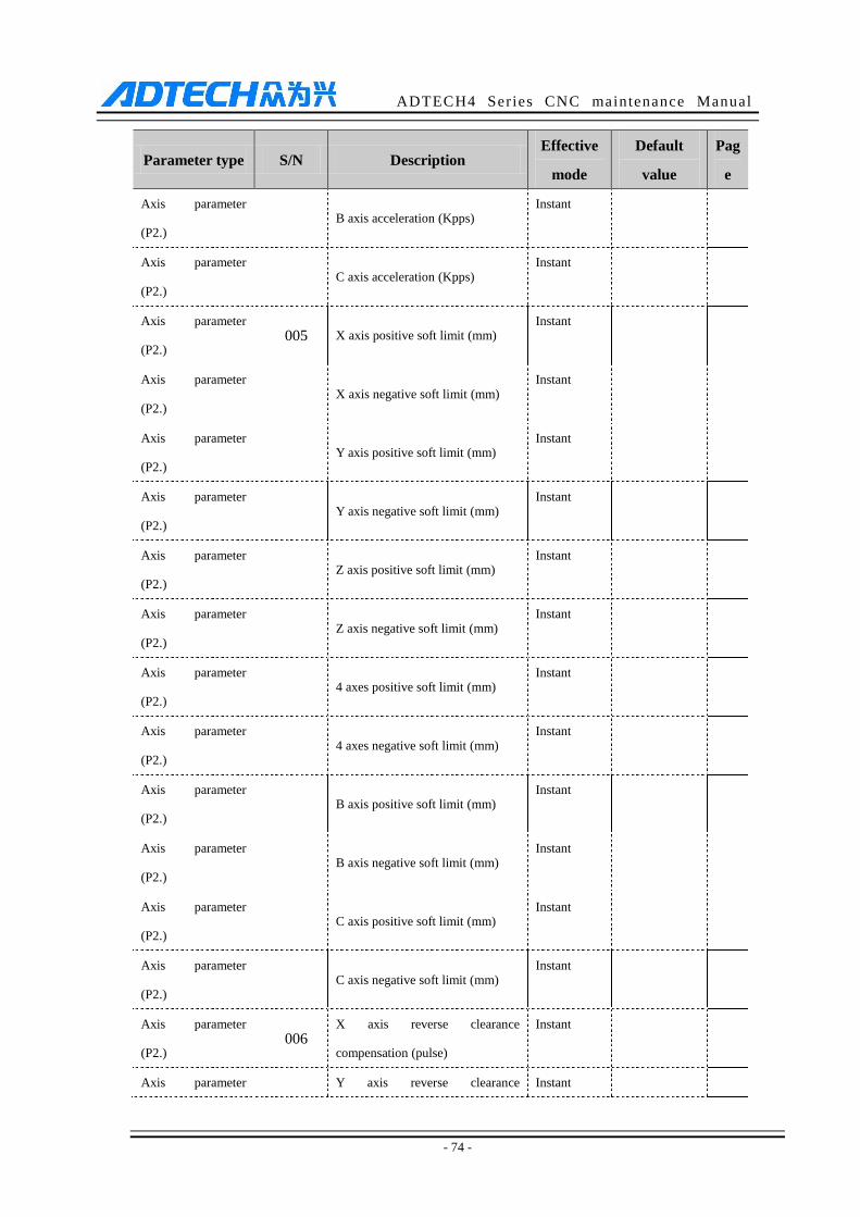
ADTECH4 Series CNC maintenance Manual
- 74 -
Parameter type S/N Description Effective
mode
Default
value
Pag
e
Axis parameter
(P2.) B axis acceleration (Kpps)
Instant
Axis parameter
(P2.) C axis acceleration (Kpps)
Instant
Axis parameter
(P2.) 005 X axis positive soft limit (mm)
Instant
Axis parameter
(P2.) X axis negative soft limit (mm)
Instant
Axis parameter
(P2.) Y axis positive soft limit (mm)
Instant
Axis parameter
(P2.) Y axis negative soft limit (mm)
Instant
Axis parameter
(P2.) Z axis positive soft limit (mm)
Instant
Axis parameter
(P2.) Z axis negative soft limit (mm)
Instant
Axis parameter
(P2.) 4 axes positive soft limit (mm)
Instant
Axis parameter
(P2.) 4 axes negative soft limit (mm)
Instant
Axis parameter
(P2.) B axis positive soft limit (mm)
Instant
Axis parameter
(P2.) B axis negative soft limit (mm)
Instant
Axis parameter
(P2.) C axis positive soft limit (mm)
Instant
Axis parameter
(P2.) C axis negative soft limit (mm)
Instant
Axis parameter
(P2.) 006
X axis reverse clearance
compensation (pulse)
Instant
Axis parameter Y axis reverse clearance Instant
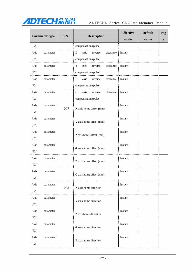
ADTECH4 Series CNC maintenance Manual
- 75 -
Parameter type S/N Description Effective
mode
Default
value
Pag
e
(P2.) compensation (pulse)
Axis parameter
(P2.)
Z axis reverse clearance
compensation (pulse)
Instant
Axis parameter
(P2.)
4 axes reverse clearance
compensation (pulse)
Instant
Axis parameter
(P2.)
B axis reverse clearance
compensation (pulse)
Instant
Axis parameter
(P2.)
C axis reverse clearance
compensation (pulse)
Instant
Axis parameter
(P2.) 007 X axis home offset (mm)
Instant
Axis parameter
(P2.) Y axis home offset (mm)
Instant
Axis parameter
(P2.) Z axis home offset (mm)
Instant
Axis parameter
(P2.) 4 axes home offset (mm)
Instant
Axis parameter
(P2.) B axis home offset (mm)
Instant
Axis parameter
(P2.) C axis home offset (mm)
Instant
Axis parameter
(P2.) 008 X axis home direction
Instant
Axis parameter
(P2.) Y axis home direction
Instant
Axis parameter
(P2.) Z axis home direction
Instant
Axis parameter
(P2.) 4 axes home direction
Instant
Axis parameter
(P2.) B axis home direction
Instant
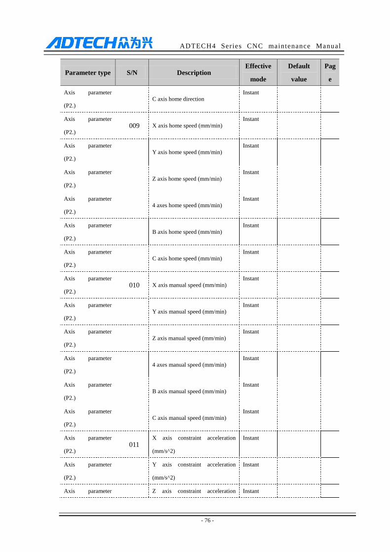
ADTECH4 Series CNC maintenance Manual
- 76 -
Parameter type S/N Description Effective
mode
Default
value
Pag
e
Axis parameter
(P2.) C axis home direction
Instant
Axis parameter
(P2.) 009 X axis home speed (mm/min)
Instant
Axis parameter
(P2.) Y axis home speed (mm/min)
Instant
Axis parameter
(P2.) Z axis home speed (mm/min)
Instant
Axis parameter
(P2.) 4 axes home speed (mm/min)
Instant
Axis parameter
(P2.) B axis home speed (mm/min)
Instant
Axis parameter
(P2.) C axis home speed (mm/min)
Instant
Axis parameter
(P2.) 010 X axis manual speed (mm/min)
Instant
Axis parameter
(P2.) Y axis manual speed (mm/min)
Instant
Axis parameter
(P2.) Z axis manual speed (mm/min)
Instant
Axis parameter
(P2.) 4 axes manual speed (mm/min)
Instant
Axis parameter
(P2.) B axis manual speed (mm/min)
Instant
Axis parameter
(P2.) C axis manual speed (mm/min)
Instant
Axis parameter
(P2.) 011
X axis constraint acceleration
(mm/s^2)
Instant
Axis parameter
(P2.)
Y axis constraint acceleration
(mm/s^2)
Instant
Axis parameter Z axis constraint acceleration Instant
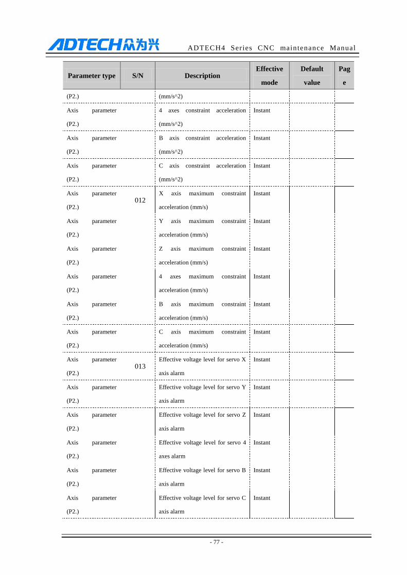
ADTECH4 Series CNC maintenance Manual
- 77 -
Parameter type S/N Description Effective
mode
Default
value
Pag
e
(P2.) (mm/s^2)
Axis parameter
(P2.)
4 axes constraint acceleration
(mm/s^2)
Instant
Axis parameter
(P2.)
B axis constraint acceleration
(mm/s^2)
Instant
Axis parameter
(P2.)
C axis constraint acceleration
(mm/s^2)
Instant
Axis parameter
(P2.) 012
X axis maximum constraint
acceleration (mm/s)
Instant
Axis parameter
(P2.)
Y axis maximum constraint
acceleration (mm/s)
Instant
Axis parameter
(P2.)
Z axis maximum constraint
acceleration (mm/s)
Instant
Axis parameter
(P2.)
4 axes maximum constraint
acceleration (mm/s)
Instant
Axis parameter
(P2.)
B axis maximum constraint
acceleration (mm/s)
Instant
Axis parameter
(P2.)
C axis maximum constraint
acceleration (mm/s)
Instant
Axis parameter
(P2.) 013
Effective voltage level for servo X
axis alarm
Instant
Axis parameter
(P2.)
Effective voltage level for servo Y
axis alarm
Instant
Axis parameter
(P2.)
Effective voltage level for servo Z
axis alarm
Instant
Axis parameter
(P2.)
Effective voltage level for servo 4
axes alarm
Instant
Axis parameter
(P2.)
Effective voltage level for servo B
axis alarm
Instant
Axis parameter
(P2.)
Effective voltage level for servo C
axis alarm
Instant
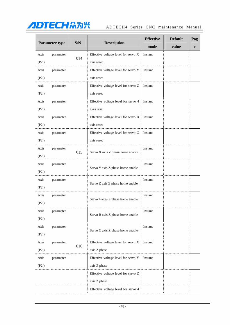
ADTECH4 Series CNC maintenance Manual
- 78 -
Parameter type S/N Description Effective
mode
Default
value
Pag
e
Axis parameter
(P2.) 014
Effective voltage level for servo X
axis reset
Instant
Axis parameter
(P2.)
Effective voltage level for servo Y
axis reset
Instant
Axis parameter
(P2.)
Effective voltage level for servo Z
axis reset
Instant
Axis parameter
(P2.)
Effective voltage level for servo 4
axes reset
Instant
Axis parameter
(P2.)
Effective voltage level for servo B
axis reset
Instant
Axis parameter
(P2.)
Effective voltage level for servo C
axis reset
Instant
Axis parameter
(P2.) 015 Servo X axis Z phase home enable
Instant
Axis parameter
(P2.) Servo Y axis Z phase home enable
Instant
Axis parameter
(P2.) Servo Z axis Z phase home enable
Instant
Axis parameter
(P2.) Servo 4 axes Z phase home enable
Instant
Axis parameter
(P2.) Servo B axis Z phase home enable
Instant
Axis parameter
(P2.) Servo C axis Z phase home enable
Instant
Axis parameter
(P2.) 016
Effective voltage level for servo X
axis Z phase
Instant
Axis parameter
(P2.)
Effective voltage level for servo Y
axis Z phase
Instant
Effective voltage level for servo Z
axis Z phase
Effective voltage level for servo 4
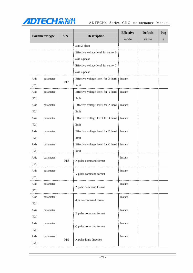
ADTECH4 Series CNC maintenance Manual
- 79 -
Parameter type S/N Description Effective
mode
Default
value
Pag
e
axes Z phase
Effective voltage level for servo B
axis Z phase
Effective voltage level for servo C
axis Z phase
Axis parameter
(P2.) 017
Effective voltage level for X hard
limit
Instant
Axis parameter
(P2.)
Effective voltage level for Y hard
limit
Instant
Axis parameter
(P2.)
Effective voltage level for Z hard
limit
Instant
Axis parameter
(P2.)
Effective voltage level for 4 hard
limit
Instant
Axis parameter
(P2.)
Effective voltage level for B hard
limit
Instant
Axis parameter
(P2.)
Effective voltage level for C hard
limit
Instant
Axis parameter
(P2.) 018 X pulse command format
Instant
Axis parameter
(P2.) Y pulse command format
Instant
Axis parameter
(P2.) Z pulse command format
Instant
Axis parameter
(P2.) 4 pulse command format
Instant
Axis parameter
(P2.) B pulse command format
Instant
Axis parameter
(P2.) C pulse command format
Instant
Axis parameter
(P2.) 019 X pulse logic direction
Instant
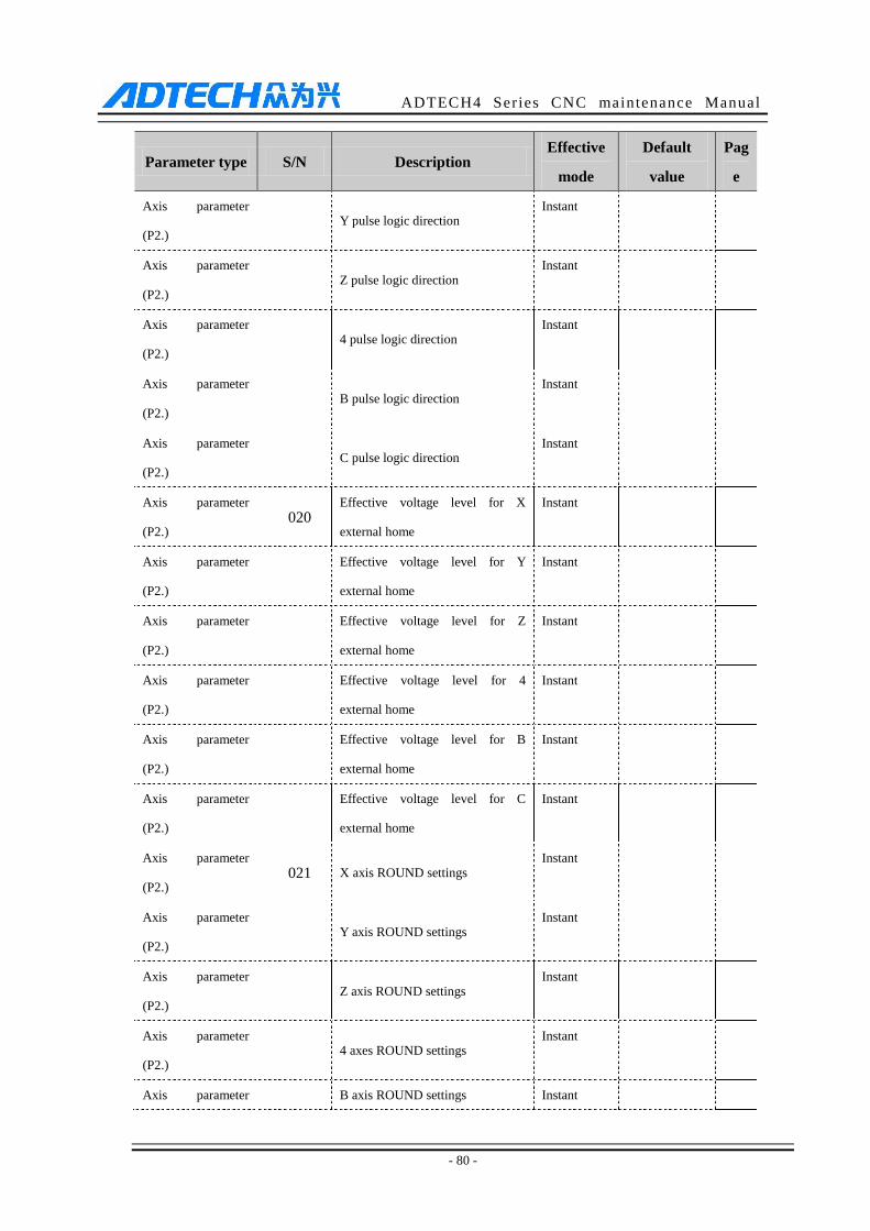
ADTECH4 Series CNC maintenance Manual
- 80 -
Parameter type S/N Description Effective
mode
Default
value
Pag
e
Axis parameter
(P2.) Y pulse logic direction
Instant
Axis parameter
(P2.) Z pulse logic direction
Instant
Axis parameter
(P2.) 4 pulse logic direction
Instant
Axis parameter
(P2.) B pulse logic direction
Instant
Axis parameter
(P2.) C pulse logic direction
Instant
Axis parameter
(P2.) 020
Effective voltage level for X
external home
Instant
Axis parameter
(P2.)
Effective voltage level for Y
external home
Instant
Axis parameter
(P2.)
Effective voltage level for Z
external home
Instant
Axis parameter
(P2.)
Effective voltage level for 4
external home
Instant
Axis parameter
(P2.)
Effective voltage level for B
external home
Instant
Axis parameter
(P2.)
Effective voltage level for C
external home
Instant
Axis parameter
(P2.) 021 X axis ROUND settings
Instant
Axis parameter
(P2.) Y axis ROUND settings
Instant
Axis parameter
(P2.) Z axis ROUND settings
Instant
Axis parameter
(P2.) 4 axes ROUND settings
Instant
Axis parameter B axis ROUND settings Instant
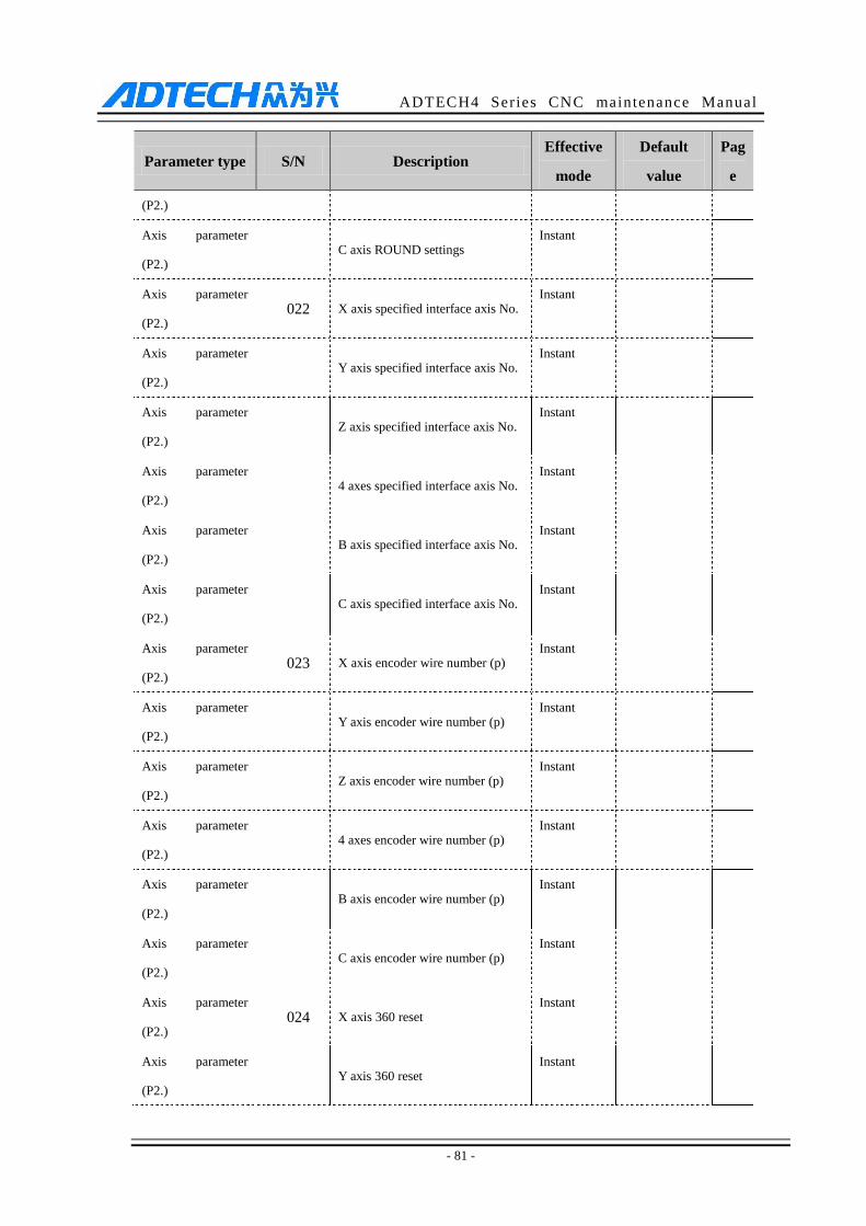
ADTECH4 Series CNC maintenance Manual
- 81 -
Parameter type S/N Description Effective
mode
Default
value
Pag
e
(P2.)
Axis parameter
(P2.) C axis ROUND settings
Instant
Axis parameter
(P2.) 022 X axis specified interface axis No.
Instant
Axis parameter
(P2.) Y axis specified interface axis No.
Instant
Axis parameter
(P2.) Z axis specified interface axis No.
Instant
Axis parameter
(P2.) 4 axes specified interface axis No.
Instant
Axis parameter
(P2.) B axis specified interface axis No.
Instant
Axis parameter
(P2.) C axis specified interface axis No.
Instant
Axis parameter
(P2.) 023 X axis encoder wire number (p)
Instant
Axis parameter
(P2.) Y axis encoder wire number (p)
Instant
Axis parameter
(P2.) Z axis encoder wire number (p)
Instant
Axis parameter
(P2.) 4 axes encoder wire number (p)
Instant
Axis parameter
(P2.) B axis encoder wire number (p)
Instant
Axis parameter
(P2.) C axis encoder wire number (p)
Instant
Axis parameter
(P2.) 024 X axis 360 reset
Instant
Axis parameter
(P2.) Y axis 360 reset
Instant
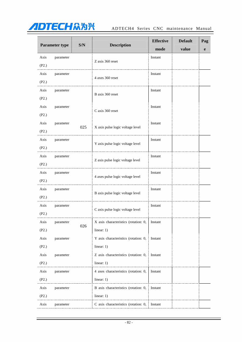
ADTECH4 Series CNC maintenance Manual
- 82 -
Parameter type S/N Description Effective
mode
Default
value
Pag
e
Axis parameter
(P2.) Z axis 360 reset
Instant
Axis parameter
(P2.) 4 axes 360 reset
Instant
Axis parameter
(P2.) B axis 360 reset
Instant
Axis parameter
(P2.) C axis 360 reset
Instant
Axis parameter
(P2.) 025 X axis pulse logic voltage level
Instant
Axis parameter
(P2.) Y axis pulse logic voltage level
Instant
Axis parameter
(P2.) Z axis pulse logic voltage level
Instant
Axis parameter
(P2.) 4 axes pulse logic voltage level
Instant
Axis parameter
(P2.) B axis pulse logic voltage level
Instant
Axis parameter
(P2.) C axis pulse logic voltage level
Instant
Axis parameter
(P2.) 026
X axis characteristics (rotation: 0,
linear: 1)
Instant
Axis parameter
(P2.)
Y axis characteristics (rotation: 0,
linear: 1)
Instant
Axis parameter
(P2.)
Z axis characteristics (rotation: 0,
linear: 1)
Instant
Axis parameter
(P2.)
4 axes characteristics (rotation: 0,
linear: 1)
Instant
Axis parameter
(P2.)
B axis characteristics (rotation: 0,
linear: 1)
Instant
Axis parameter C axis characteristics (rotation: 0, Instant
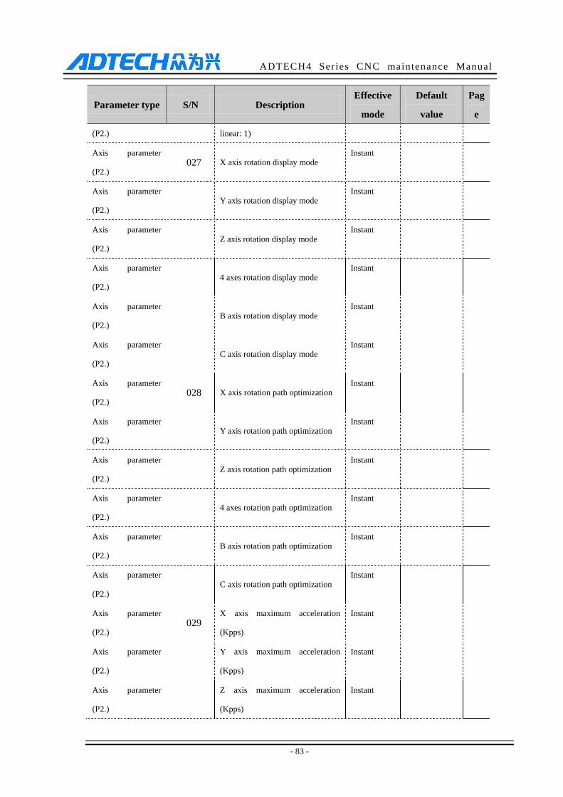
ADTECH4 Series CNC maintenance Manual
- 83 -
Parameter type S/N Description Effective
mode
Default
value
Pag
e
(P2.) linear: 1)
Axis parameter
(P2.) 027 X axis rotation display mode
Instant
Axis parameter
(P2.) Y axis rotation display mode
Instant
Axis parameter
(P2.) Z axis rotation display mode
Instant
Axis parameter
(P2.) 4 axes rotation display mode
Instant
Axis parameter
(P2.) B axis rotation display mode
Instant
Axis parameter
(P2.) C axis rotation display mode
Instant
Axis parameter
(P2.) 028 X axis rotation path optimization
Instant
Axis parameter
(P2.) Y axis rotation path optimization
Instant
Axis parameter
(P2.) Z axis rotation path optimization
Instant
Axis parameter
(P2.) 4 axes rotation path optimization
Instant
Axis parameter
(P2.) B axis rotation path optimization
Instant
Axis parameter
(P2.) C axis rotation path optimization
Instant
Axis parameter
(P2.) 029
X axis maximum acceleration
(Kpps)
Instant
Axis parameter
(P2.)
Y axis maximum acceleration
(Kpps)
Instant
Axis parameter
(P2.)
Z axis maximum acceleration
(Kpps)
Instant

ADTECH4 Series CNC maintenance Manual
- 84 -
Parameter type S/N Description Effective
mode
Default
value
Pag
e
Axis parameter
(P2.)
4 axes maximum acceleration
(Kpps)
Instant
Axis parameter
(P2.)
B axis maximum acceleration
(Kpps)
Instant
Axis parameter
(P2.)
C axis maximum acceleration
(Kpps)
Instant
Axis parameter
(P2.) 030 X servo home direction
Instant
Axis parameter
(P2.) Y servo home direction
Instant
Axis parameter
(P2.) Z servo home direction
Instant
Axis parameter
(P2.) 4 servo home direction
Instant
Axis parameter
(P2.) B servo home direction
Instant
Axis parameter
(P2.) C servo home direction
Instant
Axis parameter
(P2.) 031 X axis external home enable
Instant
Axis parameter
(P2.) Y axis external home enable
Instant
Axis parameter
(P2.) Z axis external home enable
Instant
Axis parameter
(P2.) 4 axes external home enable
Instant
Axis parameter
(P2.) B axis external home enable
Instant
Axis parameter
(P2.) C axis external home enable
Instant
Axis parameter 032 X axis encoder pulse logic Instant

ADTECH4 Series CNC maintenance Manual
- 85 -
Parameter type S/N Description Effective
mode
Default
value
Pag
e
(P2.) direction
Axis parameter
(P2.)
Y axis encoder pulse logic
direction
Instant
Axis parameter
(P2.)
Z axis encoder pulse logic
direction
Instant
Axis parameter
(P2.)
4 axes encoder pulse logic
direction
Instant
Axis parameter
(P2.)
B axis encoder pulse logic
direction
Instant
Axis parameter
(P2.)
C axis encoder pulse logic
direction
Instant
Axis parameter
(P2.) 033 X axis home deceleration speed
Instant
Axis parameter
(P2.) Y axis home deceleration speed
Instant
Axis parameter
(P2.) Z axis home deceleration speed
Instant
Axis parameter
(P2.) 4 axes home deceleration speed
Instant
Axis parameter
(P2.) B axis home deceleration speed
Instant
Axis parameter
(P2.) C axis home deceleration speed
Instant
Axis parameter
(P2.) 034 X axis home scanning speed
Instant
Axis parameter
(P2.) Y axis home scanning speed
Instant
Axis parameter
(P2.) Z axis home scanning speed
Instant
Axis parameter
(P2.) 4 axes home scanning speed
Instant

ADTECH4 Series CNC maintenance Manual
- 86 -
Parameter type S/N Description Effective
mode
Default
value
Pag
e
Axis parameter
(P2.) B axis home scanning speed
Instant
Axis parameter
(P2.) C axis home scanning speed
Instant
Axis parameter
(P2.) 035 X axis screw interpolation enable
Instant
Axis parameter
(P2.) Y axis screw interpolation enable
Instant
Axis parameter
(P2.) Z axis screw interpolation enable
Instant
Axis parameter
(P2.) 4 axes screw interpolation enable
Instant
Axis parameter
(P2.) B axis screw interpolation enable
Instant
Axis parameter
(P2.) C axis screw interpolation enable
Instant
Axis parameter
(P2.) 036
X axis screw interpolation pitch
(mm)
Instant
Axis parameter
(P2.)
Y axis screw interpolation pitch
(mm)
Instant
Axis parameter
(P2.)
Z axis screw interpolation pitch
(mm)
Instant
Axis parameter
(P2.)
4 axes screw interpolation pitch
(mm)
Instant
Axis parameter
(P2.)
B axis screw interpolation pitch
(mm)
Instant
Axis parameter
(P2.)
C axis screw interpolation pitch
(mm)
Instant
Axis parameter
(P2.) 037
X axis screw interpolation starting
position (mm)
Instant
Axis parameter Y axis screw interpolation starting Instant
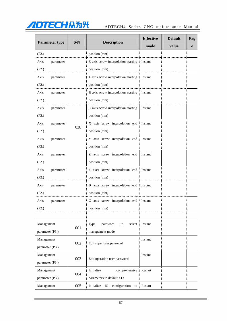
ADTECH4 Series CNC maintenance Manual
- 87 -
Parameter type S/N Description Effective
mode
Default
value
Pag
e
(P2.) position (mm)
Axis parameter
(P2.)
Z axis screw interpolation starting
position (mm)
Instant
Axis parameter
(P2.)
4 axes screw interpolation starting
position (mm)
Instant
Axis parameter
(P2.)
B axis screw interpolation starting
position (mm)
Instant
Axis parameter
(P2.)
C axis screw interpolation starting
position (mm)
Instant
Axis parameter
(P2.) 038
X axis screw interpolation end
position (mm)
Instant
Axis parameter
(P2.)
Y axis screw interpolation end
position (mm)
Instant
Axis parameter
(P2.)
Z axis screw interpolation end
position (mm)
Instant
Axis parameter
(P2.)
4 axes screw interpolation end
position (mm)
Instant
Axis parameter
(P2.)
B axis screw interpolation end
position (mm)
Instant
Axis parameter
(P2.)
C axis screw interpolation end
position (mm)
Instant
Management
parameter (P3.) 001
Type password to select
management mode
Instant
Management
parameter (P3.) 002 Edit super user password
Instant
Management
parameter (P3.) 003 Edit operation user password
Instant
Management
parameter (P3.) 004
Initialize comprehensive
parameters to default <●>
Restart
Management 005 Initialize IO configuration to Restart
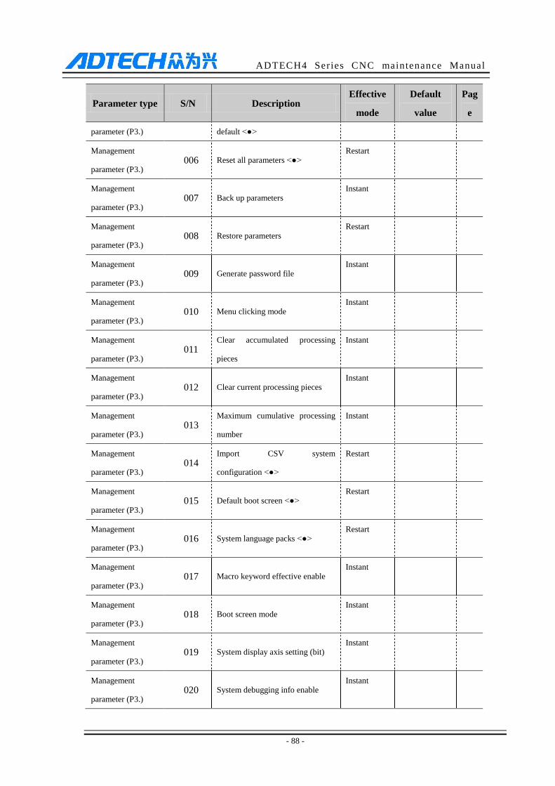
ADTECH4 Series CNC maintenance Manual
- 88 -
Parameter type S/N Description Effective
mode
Default
value
Pag
e
parameter (P3.) default <●>
Management
parameter (P3.) 006 Reset all parameters <●>
Restart
Management
parameter (P3.) 007 Back up parameters
Instant
Management
parameter (P3.) 008 Restore parameters
Restart
Management
parameter (P3.) 009 Generate password file
Instant
Management
parameter (P3.) 010 Menu clicking mode
Instant
Management
parameter (P3.) 011
Clear accumulated processing
pieces
Instant
Management
parameter (P3.) 012 Clear current processing pieces
Instant
Management
parameter (P3.) 013
Maximum cumulative processing
number
Instant
Management
parameter (P3.) 014
Import CSV system
configuration <●>
Restart
Management
parameter (P3.) 015 Default boot screen <●>
Restart
Management
parameter (P3.) 016 System language packs <●>
Restart
Management
parameter (P3.) 017 Macro keyword effective enable
Instant
Management
parameter (P3.) 018 Boot screen mode
Instant
Management
parameter (P3.) 019 System display axis setting (bit)
Instant
Management
parameter (P3.) 020 System debugging info enable
Instant

ADTECH4 Series CNC maintenance Manual
- 89 -
Parameter type S/N Description Effective
mode
Default
value
Pag
e
Management
parameter (P3.) 021 Axis control composite key enable
Instant
Management
parameter (P3.) 022 Additional panel enable
Instant
Management
parameter (P3.) 023
M code macro program selection
<●>
Restart
Management
parameter (P3.) 024
T code macro program selection
<●>
Restart
Management
parameter (P3.) 025 PLC program selection <●>
Restart
Management
parameter (P3.) 026 Screen saver ON
Instant
Management
parameter (P3.) 027 Modbus master / slave setting <●>
Restart
Tool magazine
parameter (P4.) Factory custom
Instant
Spindle axis
parameter (P5.) 001
Spindle axis specified interface
No. <●>
Restart
Spindle axis
parameter (P5.) 002
Spindle axis alarm effective
voltage level
Instant
Spindle axis
parameter (P5.) 003
Spindle axis reset effective voltage
level
Instant
Spindle axis
parameter (P5.) 004
Spindle axis encoder Z phase
home enable
Instant
Spindle axis
parameter (P5.) 005
Spindle axis encoder Z phase
effective voltage level
Instant
Spindle axis
parameter (P5.) 006
Spindle axis positive limit (port
enable)
Instant
Spindle axis 007 Spindle axis negative limit (port Instant
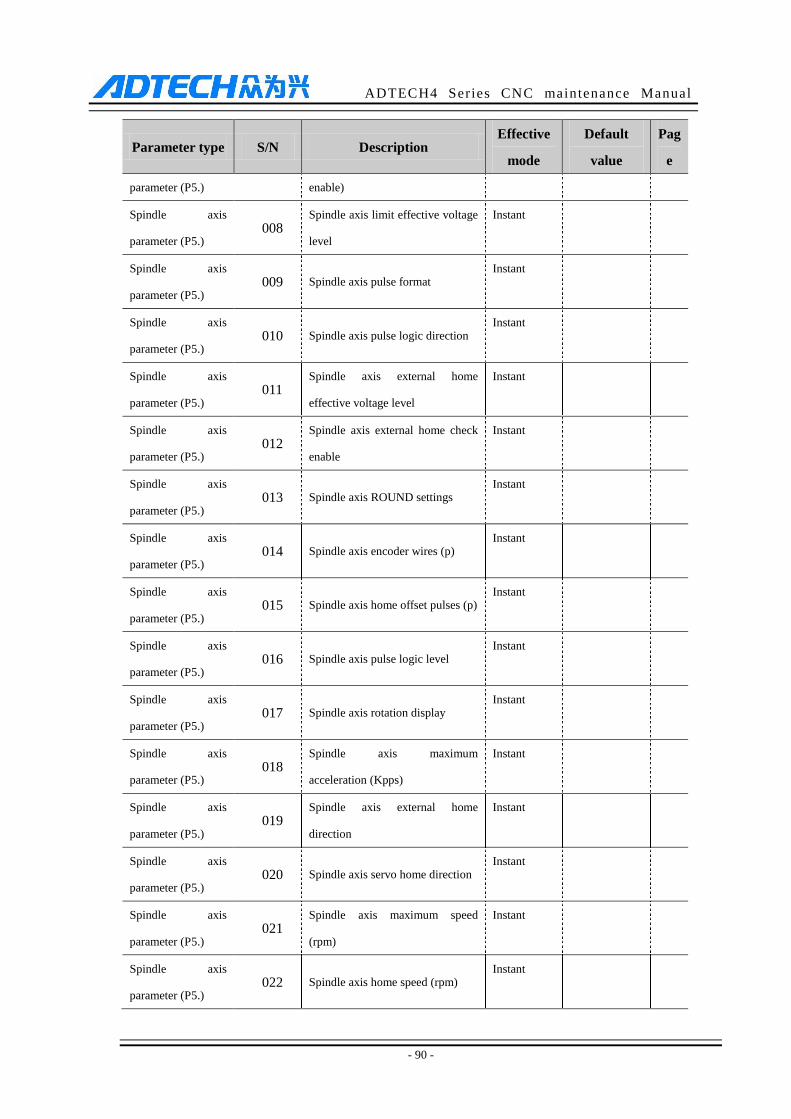
ADTECH4 Series CNC maintenance Manual
- 90 -
Parameter type S/N Description Effective
mode
Default
value
Pag
e
parameter (P5.) enable)
Spindle axis
parameter (P5.) 008
Spindle axis limit effective voltage
level
Instant
Spindle axis
parameter (P5.) 009 Spindle axis pulse format
Instant
Spindle axis
parameter (P5.) 010 Spindle axis pulse logic direction
Instant
Spindle axis
parameter (P5.) 011
Spindle axis external home
effective voltage level
Instant
Spindle axis
parameter (P5.) 012
Spindle axis external home check
enable
Instant
Spindle axis
parameter (P5.) 013 Spindle axis ROUND settings
Instant
Spindle axis
parameter (P5.) 014 Spindle axis encoder wires (p)
Instant
Spindle axis
parameter (P5.) 015 Spindle axis home offset pulses (p)
Instant
Spindle axis
parameter (P5.) 016 Spindle axis pulse logic level
Instant
Spindle axis
parameter (P5.) 017 Spindle axis rotation display
Instant
Spindle axis
parameter (P5.) 018
Spindle axis maximum
acceleration (Kpps)
Instant
Spindle axis
parameter (P5.) 019
Spindle axis external home
direction
Instant
Spindle axis
parameter (P5.) 020 Spindle axis servo home direction
Instant
Spindle axis
parameter (P5.) 021
Spindle axis maximum speed
(rpm)
Instant
Spindle axis
parameter (P5.) 022 Spindle axis home speed (rpm)
Instant
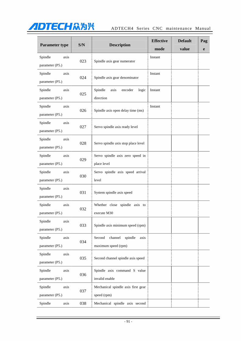
ADTECH4 Series CNC maintenance Manual
- 91 -
Parameter type S/N Description Effective
mode
Default
value
Pag
e
Spindle axis
parameter (P5.) 023 Spindle axis gear numerator
Instant
Spindle axis
parameter (P5.) 024 Spindle axis gear denominator
Instant
Spindle axis
parameter (P5.) 025
Spindle axis encoder logic
direction
Instant
Spindle axis
parameter (P5.) 026 Spindle axis open delay time (ms)
Instant
Spindle axis
parameter (P5.) 027 Servo spindle axis ready level
Spindle axis
parameter (P5.) 028 Servo spindle axis stop place level
Spindle axis
parameter (P5.) 029
Servo spindle axis zero speed in
place level
Spindle axis
parameter (P5.) 030
Servo spindle axis speed arrival
level
Spindle axis
parameter (P5.) 031 System spindle axis speed
Spindle axis
parameter (P5.) 032
Whether close spindle axis to
execute M30
Spindle axis
parameter (P5.) 033 Spindle axis minimum speed (rpm)
Spindle axis
parameter (P5.) 034
Second channel spindle axis
maximum speed (rpm)
Spindle axis
parameter (P5.) 035 Second channel spindle axis speed
Spindle axis
parameter (P5.) 036
Spindle axis command S value
invalid enable
Spindle axis
parameter (P5.) 037
Mechanical spindle axis first gear
speed (rpm)
Spindle axis 038 Mechanical spindle axis second
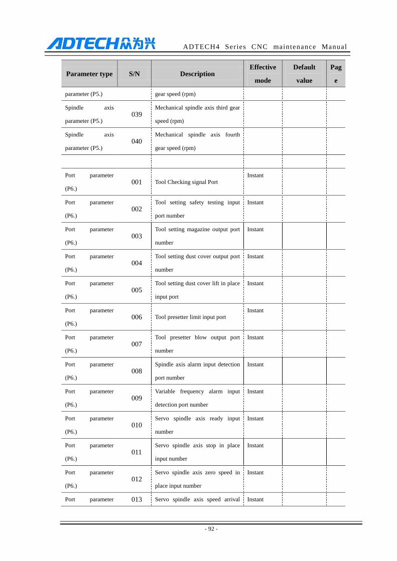
ADTECH4 Series CNC maintenance Manual
- 92 -
Parameter type S/N Description Effective
mode
Default
value
Pag
e
parameter (P5.) gear speed (rpm)
Spindle axis
parameter (P5.) 039
Mechanical spindle axis third gear
speed (rpm)
Spindle axis
parameter (P5.) 040
Mechanical spindle axis fourth
gear speed (rpm)
Port parameter
(P6.) 001 Tool Checking signal Port
Instant
Port parameter
(P6.) 002
Tool setting safety testing input
port number
Instant
Port parameter
(P6.) 003
Tool setting magazine output port
number
Instant
Port parameter
(P6.) 004
Tool setting dust cover output port
number
Instant
Port parameter
(P6.) 005
Tool setting dust cover lift in place
input port
Instant
Port parameter
(P6.) 006 Tool presetter limit input port
Instant
Port parameter
(P6.) 007
Tool presetter blow output port
number
Instant
Port parameter
(P6.) 008
Spindle axis alarm input detection
port number
Instant
Port parameter
(P6.) 009
Variable frequency alarm input
detection port number
Instant
Port parameter
(P6.) 010
Servo spindle axis ready input
number
Instant
Port parameter
(P6.) 011
Servo spindle axis stop in place
input number
Instant
Port parameter
(P6.) 012
Servo spindle axis zero speed in
place input number
Instant
Port parameter 013 Servo spindle axis speed arrival Instant

ADTECH4 Series CNC maintenance Manual
- 93 -
Parameter type S/N Description Effective
mode
Default
value
Pag
e
(P6.) input number
Port parameter
(P6.) 014
Variable frequency 0 gear output
port number
Instant
Port parameter
(P6.) 015
Variable frequency 1 gear output
port number
Instant
Port parameter
(P6.) 016
Variable frequency 2 gear output
port number
Instant
Port parameter
(P6.) 017
Variable frequency 3 gear output
port number
Instant
Port parameter
(P6.) 018
Spindle axis forward output port
number
Instant
Port parameter
(P6.) 019
Spindle axis reverse output port
number
Instant
Port parameter
(P6.) 020
Spindle axis 2 forward output port
number
Instant
Port parameter
(P6.) 021
Spindle axis 2 reverse output port
number
Instant
Port parameter
(P6.) 022
Spindle axis inverter alarm reset
output
Instant
Port parameter
(P6.) 023 Spindle axis blowing output port
Instant
Port parameter
(P6.) 024 Spindle axis brake output port
Instant
Port parameter
(P6.) 025
Servo spindle axis enable output
port number
Instant
Port parameter
(P6.) 026
Servo spindle axis stop output port
number
Instant
Port parameter
(P6.) 027
Servo spindle axis pulse control
output port number
Instant
Port parameter
(P6.) 028
Servo spindle axis rigid tapping
output port number
Instant
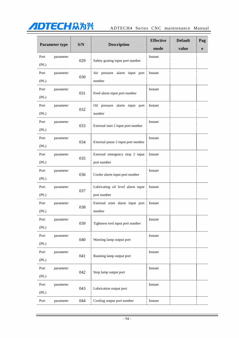
ADTECH4 Series CNC maintenance Manual
- 94 -
Parameter type S/N Description Effective
mode
Default
value
Pag
e
Port parameter
(P6.) 029 Safety grating input port number
Instant
Port parameter
(P6.) 030
Air pressure alarm input port
number
Instant
Port parameter
(P6.) 031 Feed alarm input port number
Instant
Port parameter
(P6.) 032
Oil pressure alarm input port
number
Instant
Port parameter
(P6.) 033 External start 2 input port number
Instant
Port parameter
(P6.) 034 External pause 2 input port number
Instant
Port parameter
(P6.) 035
External emergency stop 2 input
port number
Instant
Port parameter
(P6.) 036 Cooler alarm input port number
Instant
Port parameter
(P6.) 037
Lubricating oil level alarm input
port number
Instant
Port parameter
(P6.) 038
External reset alarm input port
number
Instant
Port parameter
(P6.) 039 Tightness tool input port number
Instant
Port parameter
(P6.) 040 Warning lamp output port
Instant
Port parameter
(P6.) 041 Running lamp output port
Instant
Port parameter
(P6.) 042 Stop lamp output port
Instant
Port parameter
(P6.) 043 Lubrication output port
Instant
Port parameter 044 Cooling output port number Instant
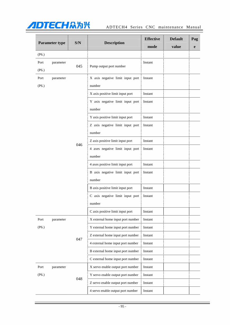
ADTECH4 Series CNC maintenance Manual
- 95 -
Parameter type S/N Description Effective
mode
Default
value
Pag
e
(P6.)
Port parameter
(P6.) 045 Pump output port number
Instant
Port parameter
(P6.)
046
X axis negative limit input port
number
Instant
X axis positive limit input port Instant
Y axis negative limit input port
number
Instant
Y axis positive limit input port Instant
Z axis negative limit input port
number
Instant
Z axis positive limit input port Instant
4 axes negative limit input port
number
Instant
4 axes positive limit input port Instant
B axis negative limit input port
number
Instant
B axis positive limit input port Instant
C axis negative limit input port
number
Instant
C axis positive limit input port Instant
Port parameter
(P6.)
047
X external home input port number Instant
Y external home input port number Instant
Z external home input port number Instant
4 external home input port number Instant
B external home input port number Instant
C external home input port number Instant
Port parameter
(P6.)
048
X servo enable output port number Instant
Y servo enable output port number Instant
Z servo enable output port number Instant
4 servo enable output port number Instant
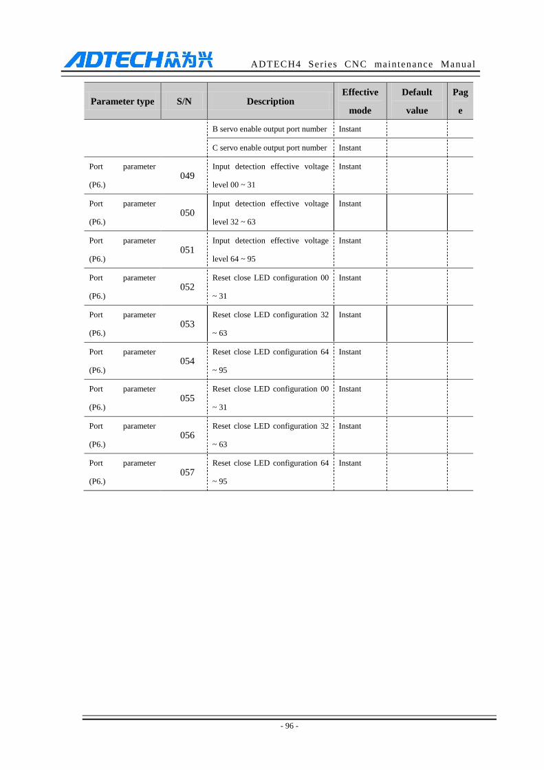
ADTECH4 Series CNC maintenance Manual
- 96 -
Parameter type S/N Description Effective
mode
Default
value
Pag
e
B servo enable output port number Instant
C servo enable output port number Instant
Port parameter
(P6.) 049
Input detection effective voltage
level 00 ~ 31
Instant
Port parameter
(P6.) 050
Input detection effective voltage
level 32 ~ 63
Instant
Port parameter
(P6.) 051
Input detection effective voltage
level 64 ~ 95
Instant
Port parameter
(P6.) 052
Reset close LED configuration 00
~ 31
Instant
Port parameter
(P6.) 053
Reset close LED configuration 32
~ 63
Instant
Port parameter
(P6.) 054
Reset close LED configuration 64
~ 95
Instant
Port parameter
(P6.) 055
Reset close LED configuration 00
~ 31
Instant
Port parameter
(P6.) 056
Reset close LED configuration 32
~ 63
Instant
Port parameter
(P6.) 057
Reset close LED configuration 64
~ 95
Instant
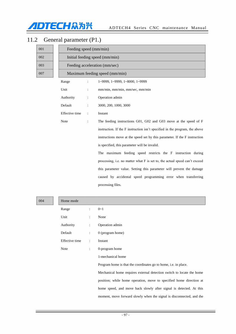
ADTECH4 Series CNC maintenance Manual
- 97 -
11.2 General parameter (P1.)
001 Feeding speed (mm/min)
002 Initial feeding speed (mm/min)
003 Feeding acceleration (mm/sec)
007 Maximum feeding speed (mm/min)
Range : 1~9999, 1~9999, 1~8000, 1~9999
Unit : mm/min, mm/min, mm/sec, mm/min
Authority : Operation admin
Default : 3000, 200, 1000, 3000
Effective time : Instant
Note : The feeding instructions G01, G02 and G03 move at the speed of F
instruction. If the F instruction isn’t specified in the program, the above
instructions move at the speed set by this parameter. If the F instruction
is specified, this parameter will be invalid.
The maximum feeding speed restricts the F instruction during
processing, i.e. no matter what F is set to, the actual speed can’t exceed
this parameter value. Setting this parameter will prevent the damage
caused by accidental speed programming error when transferring
processing files.
004 Home mode
Range : 0~1
Unit : None
Authority : Operation admin
Default : 0 (program home)
Effective time : Instant
Note : 0-program home
1-mechanical home
Program home is that the coordinates go to home, i.e. in place.
Mechanical home requires external detection switch to locate the home
position; while home operation, move to specified home direction at
home speed, and move back slowly after signal is detected. At this
moment, move forward slowly when the signal is disconnected, and the
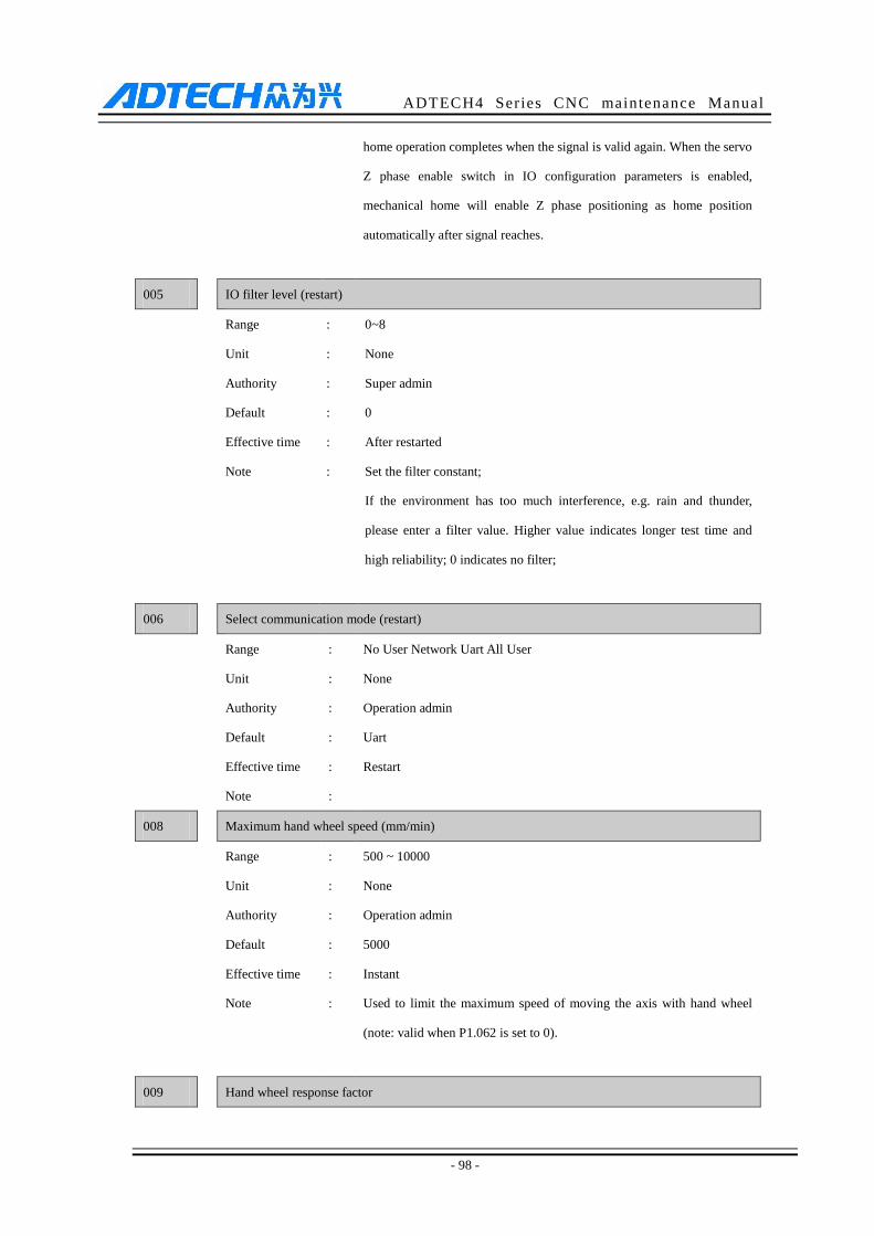
ADTECH4 Series CNC maintenance Manual
- 98 -
home operation completes when the signal is valid again. When the servo
Z phase enable switch in IO configuration parameters is enabled,
mechanical home will enable Z phase positioning as home position
automatically after signal reaches.
005 IO filter level (restart)
Range : 0~8
Unit : None
Authority : Super admin
Default : 0
Effective time : After restarted
Note : Set the filter constant;
If the environment has too much interference, e.g. rain and thunder,
please enter a filter value. Higher value indicates longer test time and
high reliability; 0 indicates no filter;
006 Select communication mode (restart)
Range : No User Network Uart All User
Unit : None
Authority : Operation admin
Default : Uart
Effective time : Restart
Note :
008 Maximum hand wheel speed (mm/min)
Range : 500 ~ 10000
Unit : None
Authority : Operation admin
Default : 5000
Effective time : Instant
Note : Used to limit the maximum speed of moving the axis with hand wheel
(note: valid when P1.062 is set to 0).
009 Hand wheel response factor
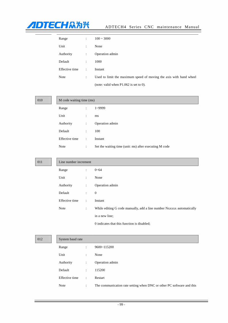
ADTECH4 Series CNC maintenance Manual
- 99 -
Range : 100 ~ 3000
Unit : None
Authority : Operation admin
Default : 1000
Effective time : Instant
Note : Used to limit the maximum speed of moving the axis with hand wheel
(note: valid when P1.062 is set to 0).
010 M code waiting time (ms)
Range : 1~9999
Unit : ms
Authority : Operation admin
Default : 100
Effective time : Instant
Note : Set the waiting time (unit: ms) after executing M code
011 Line number increment
Range : 0~64
Unit : None
Authority : Operation admin
Default : 0
Effective time : Instant
Note : While editing G code manually, add a line number Nxxxxx automatically
in a new line;
0 indicates that this function is disabled;
012 System baud rate
Range : 9600~115200
Unit : None
Authority : Operation admin
Default : 115200
Effective time : Restart
Note : The communication rate setting when DNC or other PC software and this
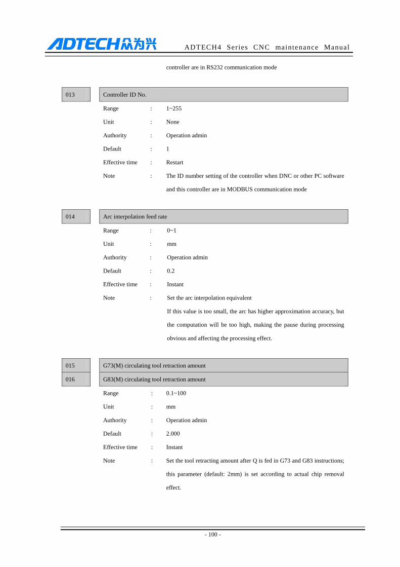
ADTECH4 Series CNC maintenance Manual
- 100 -
controller are in RS232 communication mode
013 Controller ID No.
Range : 1~255
Unit : None
Authority : Operation admin
Default : 1
Effective time : Restart
Note : The ID number setting of the controller when DNC or other PC software
and this controller are in MODBUS communication mode
014 Arc interpolation feed rate
Range : 0~1
Unit : mm
Authority : Operation admin
Default : 0.2
Effective time : Instant
Note : Set the arc interpolation equivalent
If this value is too small, the arc has higher approximation accuracy, but
the computation will be too high, making the pause during processing
obvious and affecting the processing effect.
015 G73(M) circulating tool retraction amount
016 G83(M) circulating tool retraction amount
Range : 0.1~100
Unit : mm
Authority : Operation admin
Default : 2.000
Effective time : Instant
Note : Set the tool retracting amount after Q is fed in G73 and G83 instructions;
this parameter (default: 2mm) is set according to actual chip removal
effect.

ADTECH4 Series CNC maintenance Manual
- 101 -
017 Arc interpolation processing mode
Range : Time split, position split
Unit : None
Authority : Operation admin
Default : Position split
Effective time : Instant
Note : Set the split mode of arc interpolation to position split or time split.
018 Speed optimization constraint mode
Range : Angle Speed Speed1
Unit : None
Authority : Operation admin
Default : Speed2
Effective time : Instant
Note : In pretreatment mode, set to Angle to use corner speed balancing
algorithm, or set to Speed to use axis acceleration constraints balancing
algorithm, or set to Speed1 to use efficient and quick acceleration
constraints balancing algorithm.
019 Code pretreatment processing mode
Range : 0~1
Unit : None
Authority : Operation admin
Default : 0 (rear-time processing)
Effective time : Instant
Note : Real-time processing is suitable for machine test.
In pretreatment mode, the system enters processing state buffs for two
seconds and pre-reads. The pretreatment mode only can check the
direction and size of feeding segment to adjust the speed automatically
and process at optimized speed.
020 CNC file scan flag
Range : 0~1
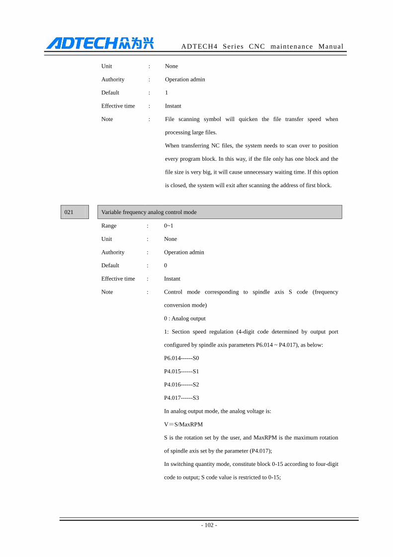
ADTECH4 Series CNC maintenance Manual
- 102 -
Unit : None
Authority : Operation admin
Default : 1
Effective time : Instant
Note : File scanning symbol will quicken the file transfer speed when
processing large files.
When transferring NC files, the system needs to scan over to position
every program block. In this way, if the file only has one block and the
file size is very big, it will cause unnecessary waiting time. If this option
is closed, the system will exit after scanning the address of first block.
021 Variable frequency analog control mode
Range : 0~1
Unit : None
Authority : Operation admin
Default : 0
Effective time : Instant
Note : Control mode corresponding to spindle axis S code (frequency
conversion mode)
0 : Analog output
1: Section speed regulation (4-digit code determined by output port
configured by spindle axis parameters P6.014 ~ P4.017), as below:
P6.014------S0
P4.015------S1
P4.016------S2
P4.017------S3
In analog output mode, the analog voltage is:
V=S/MaxRPM
S is the rotation set by the user, and MaxRPM is the maximum rotation
of spindle axis set by the parameter (P4.017);
In switching quantity mode, constitute block 0-15 according to four-digit
code to output; S code value is restricted to 0-15;
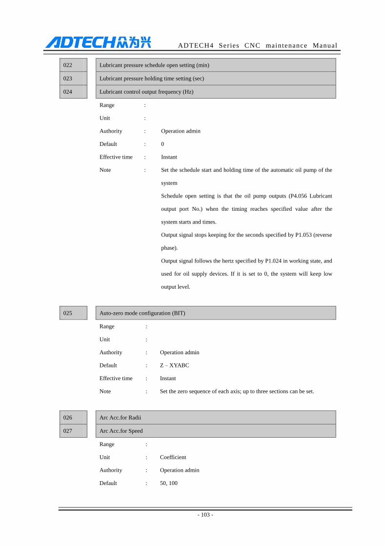
ADTECH4 Series CNC maintenance Manual
- 103 -
022 Lubricant pressure schedule open setting (min)
023 Lubricant pressure holding time setting (sec)
024 Lubricant control output frequency (Hz)
Range :
Unit :
Authority : Operation admin
Default : 0
Effective time
Note
:
:
Instant
Set the schedule start and holding time of the automatic oil pump of the
system
Schedule open setting is that the oil pump outputs (P4.056 Lubricant
output port No.) when the timing reaches specified value after the
system starts and times.
Output signal stops keeping for the seconds specified by P1.053 (reverse
phase).
Output signal follows the hertz specified by P1.024 in working state, and
used for oil supply devices. If it is set to 0, the system will keep low
output level.
025 Auto-zero mode configuration (BIT)
Range :
Unit :
Authority : Operation admin
Default : Z – XYABC
Effective time : Instant
Note : Set the zero sequence of each axis; up to three sections can be set.
026 Arc Acc.for Radii
027 Arc Acc.for Speed
Range :
Unit : Coefficient
Authority : Operation admin
Default : 50, 100
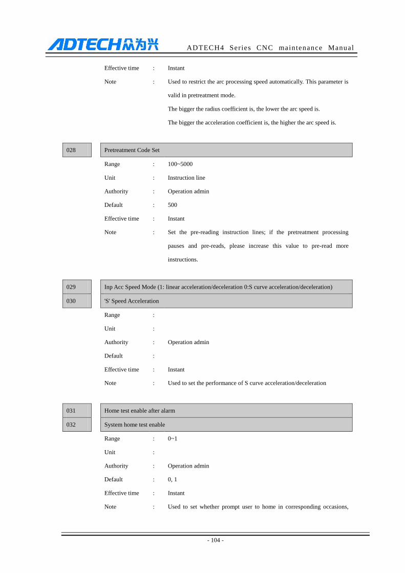
ADTECH4 Series CNC maintenance Manual
- 104 -
Effective time : Instant
Note : Used to restrict the arc processing speed automatically. This parameter is
valid in pretreatment mode.
The bigger the radius coefficient is, the lower the arc speed is.
The bigger the acceleration coefficient is, the higher the arc speed is.
028 Pretreatment Code Set
Range : 100~5000
Unit : Instruction line
Authority : Operation admin
Default : 500
Effective time : Instant
Note : Set the pre-reading instruction lines; if the pretreatment processing
pauses and pre-reads, please increase this value to pre-read more
instructions.
029 Inp Acc Speed Mode (1: linear acceleration/deceleration 0:S curve acceleration/deceleration)
030 'S' Speed Acceleration
Range :
Unit :
Authority : Operation admin
Default :
Effective time : Instant
Note : Used to set the performance of S curve acceleration/deceleration
031 Home test enable after alarm
032 System home test enable
Range : 0~1
Unit :
Authority : Operation admin
Default : 0, 1
Effective time : Instant
Note : Used to set whether prompt user to home in corresponding occasions,
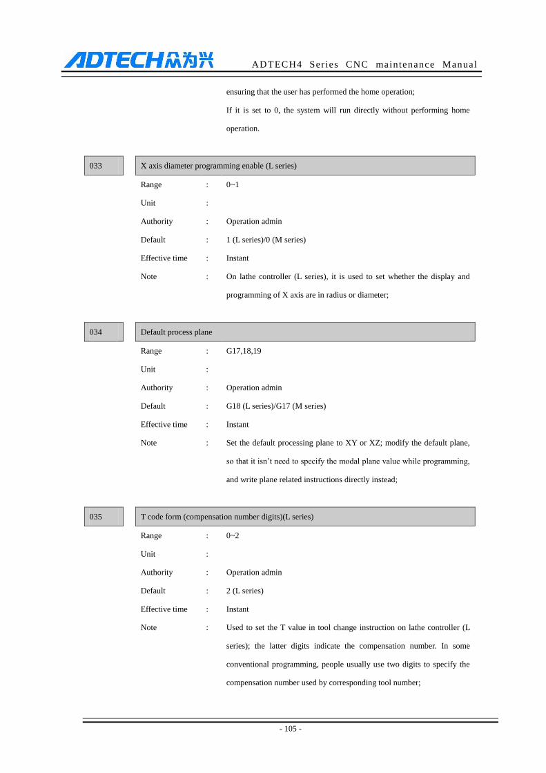
ADTECH4 Series CNC maintenance Manual
- 105 -
ensuring that the user has performed the home operation;
If it is set to 0, the system will run directly without performing home
operation.
033 X axis diameter programming enable (L series)
Range : 0~1
Unit :
Authority : Operation admin
Default : 1 (L series)/0 (M series)
Effective time : Instant
Note : On lathe controller (L series), it is used to set whether the display and
programming of X axis are in radius or diameter;
034 Default process plane
Range : G17,18,19
Unit :
Authority : Operation admin
Default : G18 (L series)/G17 (M series)
Effective time : Instant
Note : Set the default processing plane to XY or XZ; modify the default plane,
so that it isn’t need to specify the modal plane value while programming,
and write plane related instructions directly instead;
035 T code form (compensation number digits)(L series)
Range : 0~2
Unit :
Authority : Operation admin
Default : 2 (L series)
Effective time : Instant
Note : Used to set the T value in tool change instruction on lathe controller (L
series); the latter digits indicate the compensation number. In some
conventional programming, people usually use two digits to specify the
compensation number used by corresponding tool number;
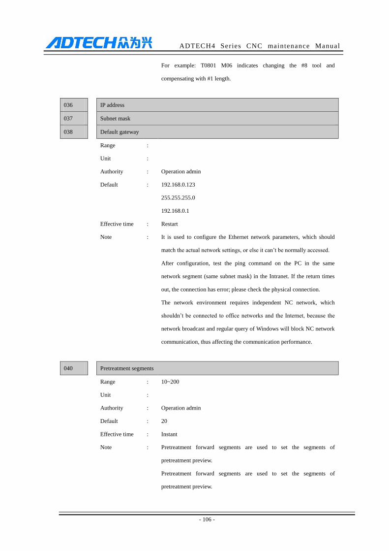
ADTECH4 Series CNC maintenance Manual
- 106 -
For example: T0801 M06 indicates changing the #8 tool and
compensating with #1 length.
036 IP address
037 Subnet mask
038 Default gateway
Range :
Unit :
Authority : Operation admin
Default : 192.168.0.123
255.255.255.0
192.168.0.1
Effective time : Restart
Note : It is used to configure the Ethernet network parameters, which should
match the actual network settings, or else it can’t be normally accessed.
After configuration, test the ping command on the PC in the same
network segment (same subnet mask) in the Intranet. If the return times
out, the connection has error; please check the physical connection.
The network environment requires independent NC network, which
shouldn’t be connected to office networks and the Internet, because the
network broadcast and regular query of Windows will block NC network
communication, thus affecting the communication performance.
040 Pretreatment segments
Range : 10~200
Unit :
Authority : Operation admin
Default : 20
Effective time : Instant
Note : Pretreatment forward segments are used to set the segments of
pretreatment preview.
Pretreatment forward segments are used to set the segments of
pretreatment preview.
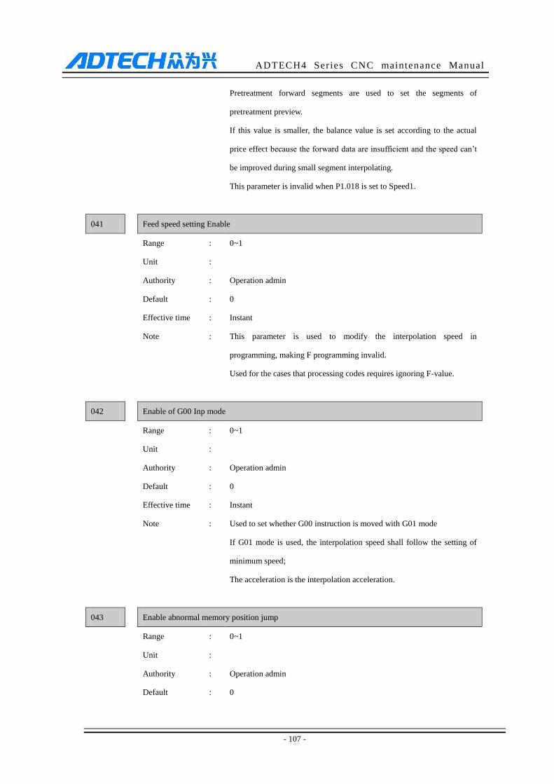
ADTECH4 Series CNC maintenance Manual
- 107 -
Pretreatment forward segments are used to set the segments of
pretreatment preview.
If this value is smaller, the balance value is set according to the actual
price effect because the forward data are insufficient and the speed can’t
be improved during small segment interpolating.
This parameter is invalid when P1.018 is set to Speed1.
041 Feed speed setting Enable
Range : 0~1
Unit :
Authority : Operation admin
Default : 0
Effective time : Instant
Note : This parameter is used to modify the interpolation speed in
programming, making F programming invalid.
Used for the cases that processing codes requires ignoring F-value.
042 Enable of G00 Inp mode
Range : 0~1
Unit :
Authority : Operation admin
Default : 0
Effective time : Instant
Note : Used to set whether G00 instruction is moved with G01 mode
If G01 mode is used, the interpolation speed shall follow the setting of
minimum speed;
The acceleration is the interpolation acceleration.
043 Enable abnormal memory position jump
Range : 0~1
Unit :
Authority : Operation admin
Default : 0
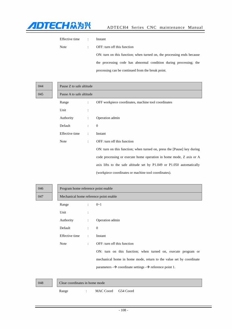
ADTECH4 Series CNC maintenance Manual
- 108 -
Effective time : Instant
Note : OFF: turn off this function
ON: turn on this function; when turned on, the processing ends because
the processing code has abnormal condition during processing; the
processing can be continued from the break point.
044
Pause Z to safe altitude
045 Pause A to safe altitude
Range : OFF workpiece coordinates, machine tool coordinates
Unit :
Authority : Operation admin
Default : 0
Effective time : Instant
Note : OFF: turn off this function
ON: turn on this function; when turned on, press the [Pause] key during
code processing or execute home operation in home mode, Z axis or A
axis lifts to the safe altitude set by P1.049 or P1.050 automatically
(workpiece coordinates or machine tool coordinates).
046
Program home reference point enable
047 Mechanical home reference point enable
Range : 0~1
Unit :
Authority : Operation admin
Default : 0
Effective time : Instant
Note : OFF: turn off this function
ON: turn on this function; when turned on, execute program or
mechanical home in home mode, return to the value set by coordinate
parameters - coordinate settings - reference point 1.
048 Clear coordinates in home mode
Range : MAC Coord G54 Coord
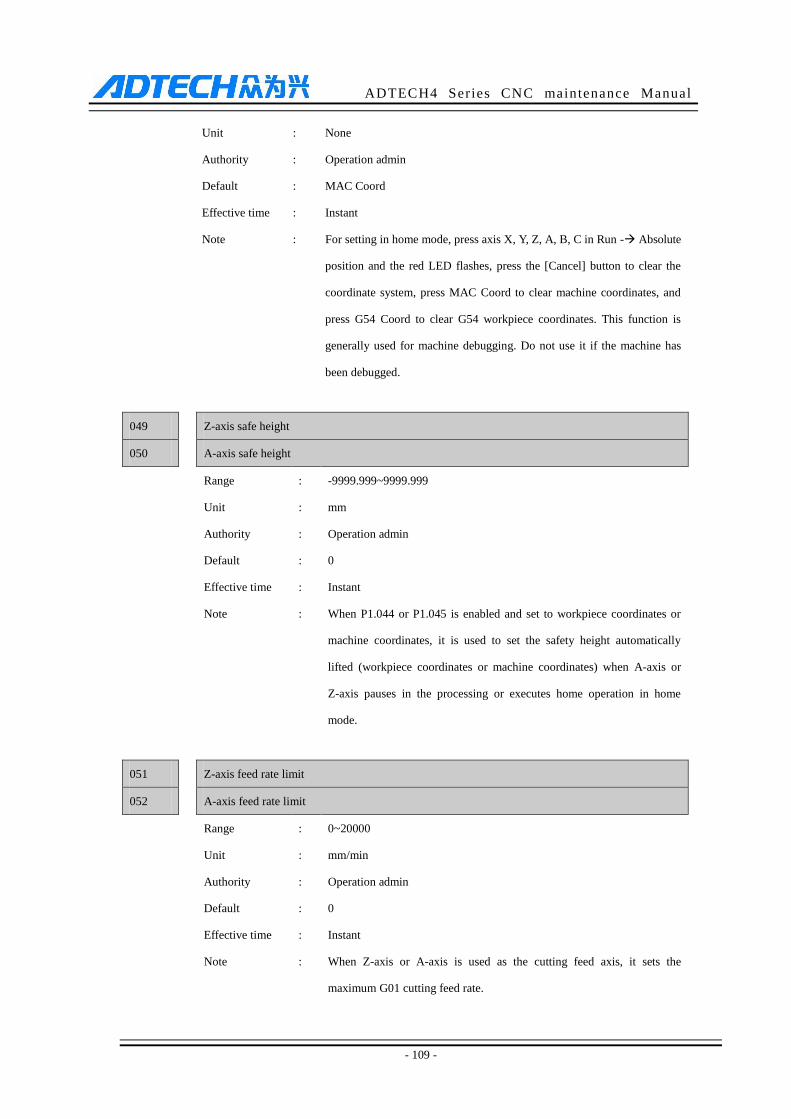
ADTECH4 Series CNC maintenance Manual
- 109 -
Unit : None
Authority : Operation admin
Default : MAC Coord
Effective time : Instant
Note : For setting in home mode, press axis X, Y, Z, A, B, C in Run - Absolute
position and the red LED flashes, press the [Cancel] button to clear the
coordinate system, press MAC Coord to clear machine coordinates, and
press G54 Coord to clear G54 workpiece coordinates. This function is
generally used for machine debugging. Do not use it if the machine has
been debugged.
049
Z-axis safe height
050 A-axis safe height
Range : -9999.999~9999.999
Unit : mm
Authority : Operation admin
Default : 0
Effective time : Instant
Note : When P1.044 or P1.045 is enabled and set to workpiece coordinates or
machine coordinates, it is used to set the safety height automatically
lifted (workpiece coordinates or machine coordinates) when A-axis or
Z-axis pauses in the processing or executes home operation in home
mode.
051
Z-axis feed rate limit
052 A-axis feed rate limit
Range : 0~20000
Unit : mm/min
Authority : Operation admin
Default : 0
Effective time : Instant
Note : When Z-axis or A-axis is used as the cutting feed axis, it sets the
maximum G01 cutting feed rate.

ADTECH4 Series CNC maintenance Manual
- 110 -
053
Thread cutting acceleration pitch P (L series)
054 Thread cutting acceleration pitch D (L series)
055 Thread cutting backslide amount V (L series)
Range : 0~100
Unit : mm
Authority : Operation admin
Default : 0
Effective time : Instant
Note : To set the pitch length of acceleration segment of lathe CNC4620 system
thread cutting command G32 & G92, pitch length of the deceleration
segment and run-out amount. For details of G32 G92 instruction, see
CNC4620 programming manual.
056 Enable jump to M98 * times * lines
Range : OFF ON
Unit : None
Authority : Operation admin
Default : OFF
Effective time : Instant
Note : Enable and set this parameter to ON to jump to line N of X cycle of M98
instruction and start processing.
057 System home ON
Range : No, ask, auto
Unit : None
Authority : Operation admin
Default : No
Effective time : Instant
Note : Ask: when the system is restarted, it asks whether to execute home
operation; press the [EOB] button to execute.
Auto: when the system is restarted, it executes home operation
automatically.
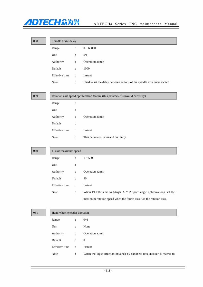
ADTECH4 Series CNC maintenance Manual
- 111 -
058 Spindle brake delay
Range : 0 ~ 60000
Unit : sec
Authority : Operation admin
Default : 1000
Effective time : Instant
Note : Used to set the delay between actions of the spindle axis brake switch
059 Rotation axis speed optimization feature (this parameter is invalid currently)
Range :
Unit :
Authority : Operation admin
Default :
Effective time : Instant
Note : This parameter is invalid currently
060 4 -axis maximum speed
Range : 1 ~ 500
Unit :
Authority : Operation admin
Default : 50
Effective time : Instant
Note : When P1.018 is set to (Angle X Y Z space angle optimization), set the
maximum rotation speed when the fourth axis A is the rotation axis.
061 Hand wheel encoder direction
Range : 0~1
Unit : None
Authority : Operation admin
Default : 0
Effective time : Instant
Note : When the logic direction obtained by handheld box encoder is reverse to
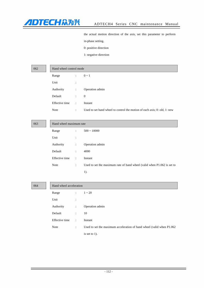
ADTECH4 Series CNC maintenance Manual
- 112 -
the actual motion direction of the axis, set this parameter to perform
in-phase setting.
0: positive direction
1: negative direction
062 Hand wheel control mode
Range : 0 ~ 1
Unit :
Authority : Operation admin
Default : 0
Effective time : Instant
Note : Used to set hand wheel to control the motion of each axis; 0: old, 1: new
063 Hand wheel maximum rate
Range : 500 ~ 10000
Unit :
Authority : Operation admin
Default : 4000
Effective time : Instant
Note : Used to set the maximum rate of hand wheel (valid when P1.062 is set to
1).
064 Hand wheel acceleration
Range : 1 ~ 20
Unit :
Authority : Operation admin
Default : 10
Effective time : Instant
Note : Used to set the maximum acceleration of hand wheel (valid when P1.062
is set to 1).

ADTECH4 Series CNC maintenance Manual
- 113 -
11.3 Axis parameter configuration (P2.)
001 X axis instruction frequency multiplication ratio
X axis instruction frequency division coefficient
Y axis instruction frequency multiplication ratio
Y axis instruction frequency division coefficient
Z axis instruction frequency multiplication ratio
Z axis instruction frequency division coefficient
4 axes instruction frequency multiplication ratio
4 axes instruction frequency division coefficient
B axis instruction frequency multiplication ratio
B axis instruction frequency division coefficient
C axis instruction frequency multiplication ratio
C axis instruction frequency division coefficient
Range : 1~65535
Unit : None
Authority : Operation admin
Default : 1
Effective
time
: Restart
Note : When screws of different pitches and motors of different step angles or
servo motors of different pulses are matched, or connected through
gears, it allows keeping the program and actual motion distance
consistent through electronic gear ratio setting of the system.
CMR/CMD =P/(L×1000)
CMR: gear ratio numerator
CMD: gear ratio denominator
P: Pulses corresponding to one rotation of the motor
L: Machine tool movement corresponding to one rotation of the motor
(mm)
CMD/CMR is the pulse equivalent actually, i.e. the motion distance
corresponding to every pulse (unit: 0.001mm).
Ex 1: the motor rotates one cycle every 5000 pulses, and the machine
tool moves 5mm when the motor rotates one cycle, then

ADTECH4 Series CNC maintenance Manual
- 114 -
CMR/CMD=5000/(5*1000)=1/1
Then, CMR=1, CMD=1, the pulse equivalent is 0.001mm
Ex 2: the motor rotates one cycle every 5000 pulses, and the machine
tool moves 10mm when the motor rotates one cycle, then
CMR/CMD=5000/(10*1000)=1/2
Then, CMR=1, CMD=2, the pulse equivalent is 0.002mm
002 X axis rapid traverse rate (mm/min)
Y axis rapid traverse rate (mm/min)
Z axis rapid traverse rate (mm/min)
4 axes rapid traverse rate (mm/min)
B axis rapid traverse rate (mm/min)
C axis rapid traverse rate (mm/min)
003 X axis start rate (mm/min)
Y axis start rate (mm/min)
Z axis start rate (mm/min)
4 axes start rate (mm/min)
B axis start rate (mm/min)
C axis start rate (mm/min)
004 X axis acceleration (Kpps)
Y axis acceleration (Kpps)
Z axis acceleration (Kpps)
4 axes acceleration (Kpps)
B axis acceleration (Kpps)
C axis acceleration (Kpps)
Range : 1~9999, 1~9999, 1~8000
Unit : mm/min, mm/min, mm/sec
Authority : Operation admin
Default : 3000, 200, 1500
Effective time : Instant
Note : This parameter is the trapezoid acceleration/deceleration setting used for
GOO instruction
About start speed, 1-2 rotation motor speed is recommended for step
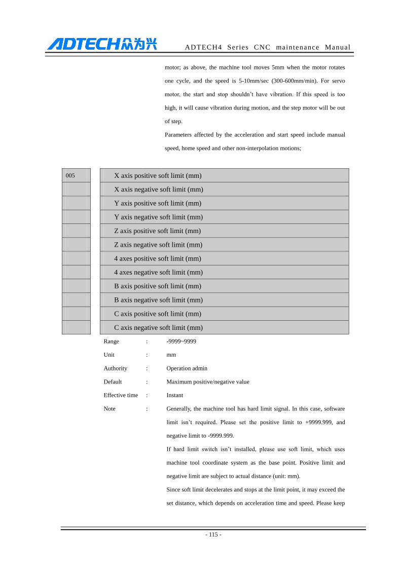
ADTECH4 Series CNC maintenance Manual
- 115 -
motor; as above, the machine tool moves 5mm when the motor rotates
one cycle, and the speed is 5-10mm/sec (300-600mm/min). For servo
motor, the start and stop shouldn’t have vibration. If this speed is too
high, it will cause vibration during motion, and the step motor will be out
of step.
Parameters affected by the acceleration and start speed include manual
speed, home speed and other non-interpolation motions;
005 X axis positive soft limit (mm)
X axis negative soft limit (mm)
Y axis positive soft limit (mm)
Y axis negative soft limit (mm)
Z axis positive soft limit (mm)
Z axis negative soft limit (mm)
4 axes positive soft limit (mm)
4 axes negative soft limit (mm)
B axis positive soft limit (mm)
B axis negative soft limit (mm)
C axis positive soft limit (mm)
C axis negative soft limit (mm)
Range : -9999~9999
Unit : mm
Authority : Operation admin
Default : Maximum positive/negative value
Effective time : Instant
Note : Generally, the machine tool has hard limit signal. In this case, software
limit isn’t required. Please set the positive limit to +9999.999, and
negative limit to -9999.999.
If hard limit switch isn’t installed, please use soft limit, which uses
machine tool coordinate system as the base point. Positive limit and
negative limit are subject to actual distance (unit: mm).
Since soft limit decelerates and stops at the limit point, it may exceed the
set distance, which depends on acceleration time and speed. Please keep
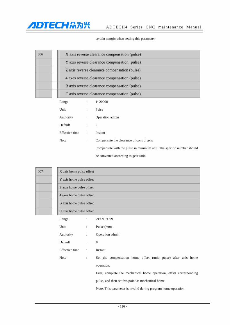
ADTECH4 Series CNC maintenance Manual
- 116 -
certain margin when setting this parameter.
006 X axis reverse clearance compensation (pulse)
Y axis reverse clearance compensation (pulse)
Z axis reverse clearance compensation (pulse)
4 axes reverse clearance compensation (pulse)
B axis reverse clearance compensation (pulse)
C axis reverse clearance compensation (pulse)
Range : 1~20000
Unit : Pulse
Authority : Operation admin
Default : 0
Effective time : Instant
Note : Compensate the clearance of control axis
Compensate with the pulse in minimum unit. The specific number should
be converted according to gear ratio.
007 X axis home pulse offset
Y axis home pulse offset
Z axis home pulse offset
4 axes home pulse offset
B axis home pulse offset
C axis home pulse offset
Range : -9999~9999
Unit : Pulse (mm)
Authority : Operation admin
Default : 0
Effective time : Instant
Note : Set the compensation home offset (unit: pulse) after axis home
operation.
First, complete the mechanical home operation, offset corresponding
pulse, and then set this point as mechanical home.
Note: This parameter is invalid during program home operation.

ADTECH4 Series CNC maintenance Manual
- 117 -
008 X axis home direction
Y axis home direction
Z axis home direction
4 axes home direction
B axis home direction
C axis home direction
Range : 0~1
Unit : None
Authority : Operation admin
Default : 1,1,0,0
Effective time : Instant
Note : Set the mechanical home direction of every processing axis
Positive direction
Negative direction
009 X axis home speed
Y axis home speed
Z axis home speed
4 axes home speed
B axis home speed
C axis home speed
Range : 0~9999
Unit : mm/min
Authority : Operation admin
Default : 1000
Effective time : Instant
Note : Set the home speed of every axis separately
010 X axis manual speed
Y axis manual speed
Z axis manual speed
4 axes manual speed
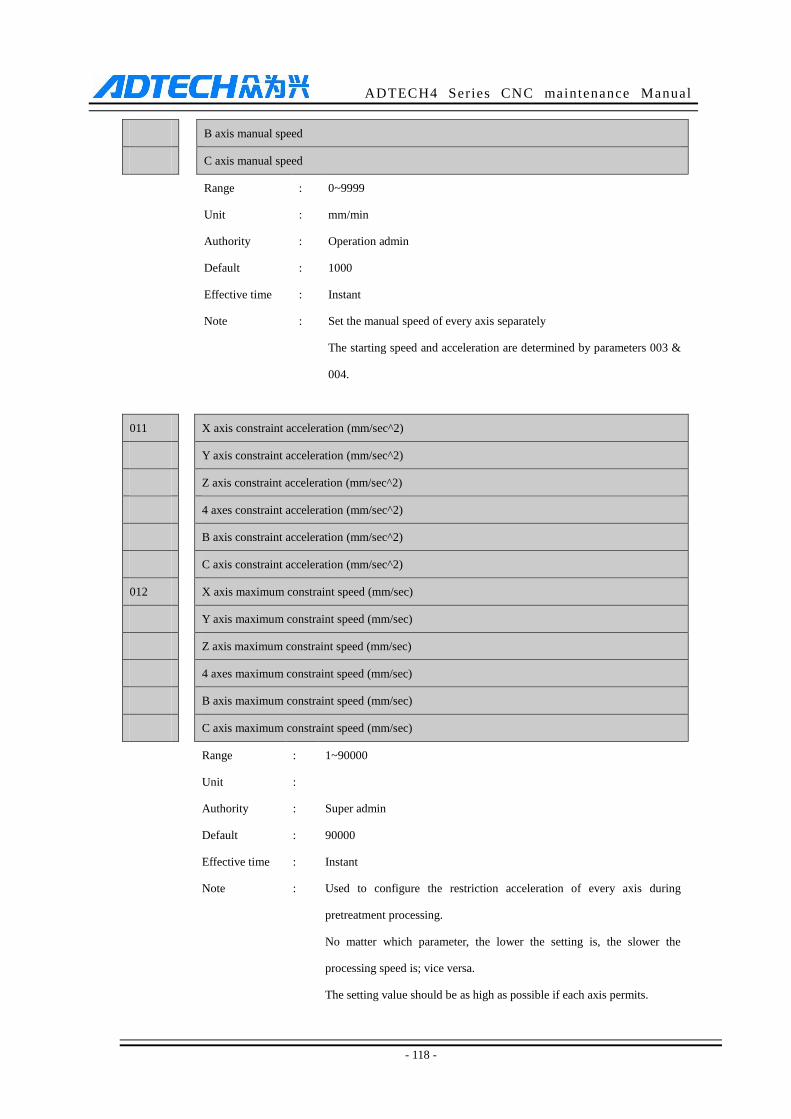
ADTECH4 Series CNC maintenance Manual
- 118 -
B axis manual speed
C axis manual speed
Range : 0~9999
Unit : mm/min
Authority : Operation admin
Default : 1000
Effective time : Instant
Note : Set the manual speed of every axis separately
The starting speed and acceleration are determined by parameters 003 &
004.
011 X axis constraint acceleration (mm/sec^2)
Y axis constraint acceleration (mm/sec^2)
Z axis constraint acceleration (mm/sec^2)
4 axes constraint acceleration (mm/sec^2)
B axis constraint acceleration (mm/sec^2)
C axis constraint acceleration (mm/sec^2)
012 X axis maximum constraint speed (mm/sec)
Y axis maximum constraint speed (mm/sec)
Z axis maximum constraint speed (mm/sec)
4 axes maximum constraint speed (mm/sec)
B axis maximum constraint speed (mm/sec)
C axis maximum constraint speed (mm/sec)
Range : 1~90000
Unit :
Authority : Super admin
Default : 90000
Effective time : Instant
Note : Used to configure the restriction acceleration of every axis during
pretreatment processing.
No matter which parameter, the lower the setting is, the slower the
processing speed is; vice versa.
The setting value should be as high as possible if each axis permits.
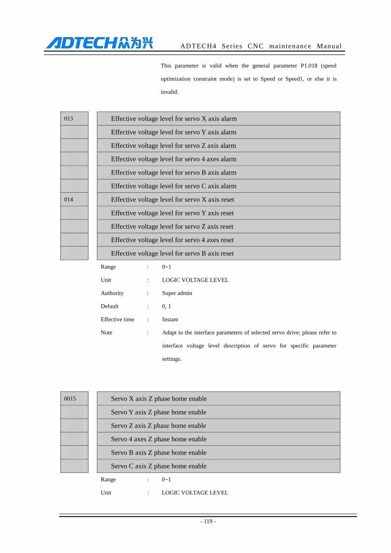
ADTECH4 Series CNC maintenance Manual
- 119 -
This parameter is valid when the general parameter P1.018 (speed
optimization constraint mode) is set to Speed or Speed1, or else it is
invalid.
013 Effective voltage level for servo X axis alarm
Effective voltage level for servo Y axis alarm
Effective voltage level for servo Z axis alarm
Effective voltage level for servo 4 axes alarm
Effective voltage level for servo B axis alarm
Effective voltage level for servo C axis alarm
014 Effective voltage level for servo X axis reset
Effective voltage level for servo Y axis reset
Effective voltage level for servo Z axis reset
Effective voltage level for servo 4 axes reset
Effective voltage level for servo B axis reset
Range : 0~1
Unit : LOGIC VOLTAGE LEVEL
Authority : Super admin
Default : 0, 1
Effective time : Instant
Note : Adapt to the interface parameters of selected servo drive; please refer to
interface voltage level description of servo for specific parameter
settings.
0015 Servo X axis Z phase home enable
Servo Y axis Z phase home enable
Servo Z axis Z phase home enable
Servo 4 axes Z phase home enable
Servo B axis Z phase home enable
Servo C axis Z phase home enable
Range : 0~1
Unit : LOGIC VOLTAGE LEVEL
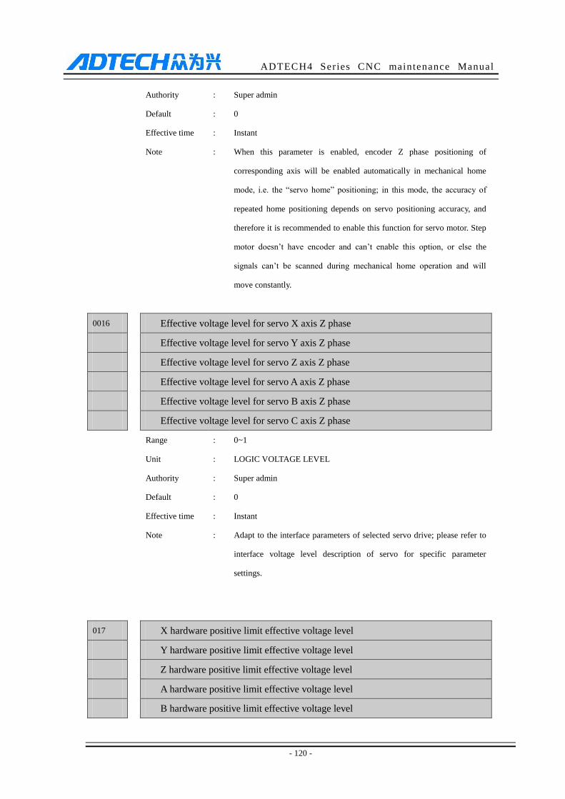
ADTECH4 Series CNC maintenance Manual
- 120 -
Authority : Super admin
Default : 0
Effective time : Instant
Note : When this parameter is enabled, encoder Z phase positioning of
corresponding axis will be enabled automatically in mechanical home
mode, i.e. the “servo home” positioning; in this mode, the accuracy of
repeated home positioning depends on servo positioning accuracy, and
therefore it is recommended to enable this function for servo motor. Step
motor doesn’t have encoder and can’t enable this option, or else the
signals can’t be scanned during mechanical home operation and will
move constantly.
0016 Effective voltage level for servo X axis Z phase
Effective voltage level for servo Y axis Z phase
Effective voltage level for servo Z axis Z phase
Effective voltage level for servo A axis Z phase
Effective voltage level for servo B axis Z phase
Effective voltage level for servo C axis Z phase
Range : 0~1
Unit : LOGIC VOLTAGE LEVEL
Authority : Super admin
Default : 0
Effective time : Instant
Note : Adapt to the interface parameters of selected servo drive; please refer to
interface voltage level description of servo for specific parameter
settings.
017 X hardware positive limit effective voltage level
Y hardware positive limit effective voltage level
Z hardware positive limit effective voltage level
A hardware positive limit effective voltage level
B hardware positive limit effective voltage level
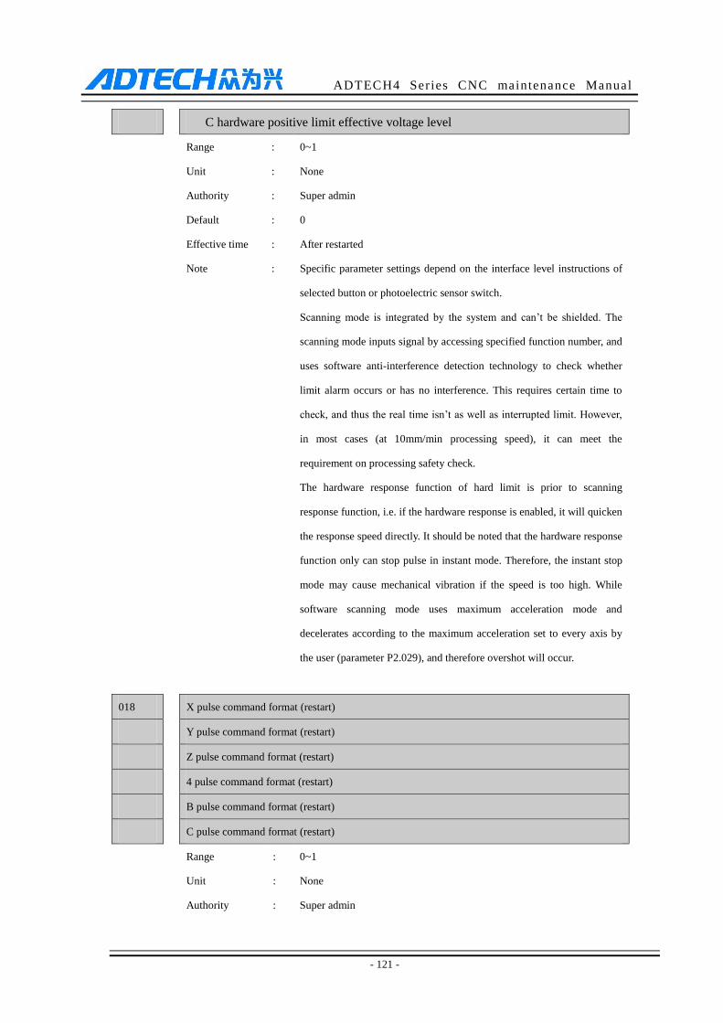
ADTECH4 Series CNC maintenance Manual
- 121 -
C hardware positive limit effective voltage level
Range : 0~1
Unit : None
Authority : Super admin
Default : 0
Effective time : After restarted
Note : Specific parameter settings depend on the interface level instructions of
selected button or photoelectric sensor switch.
Scanning mode is integrated by the system and can’t be shielded. The
scanning mode inputs signal by accessing specified function number, and
uses software anti-interference detection technology to check whether
limit alarm occurs or has no interference. This requires certain time to
check, and thus the real time isn’t as well as interrupted limit. However,
in most cases (at 10mm/min processing speed), it can meet the
requirement on processing safety check.
The hardware response function of hard limit is prior to scanning
response function, i.e. if the hardware response is enabled, it will quicken
the response speed directly. It should be noted that the hardware response
function only can stop pulse in instant mode. Therefore, the instant stop
mode may cause mechanical vibration if the speed is too high. While
software scanning mode uses maximum acceleration mode and
decelerates according to the maximum acceleration set to every axis by
the user (parameter P2.029), and therefore overshot will occur.
018 X pulse command format (restart)
Y pulse command format (restart)
Z pulse command format (restart)
4 pulse command format (restart)
B pulse command format (restart)
C pulse command format (restart)
Range : 0~1
Unit : None
Authority : Super admin
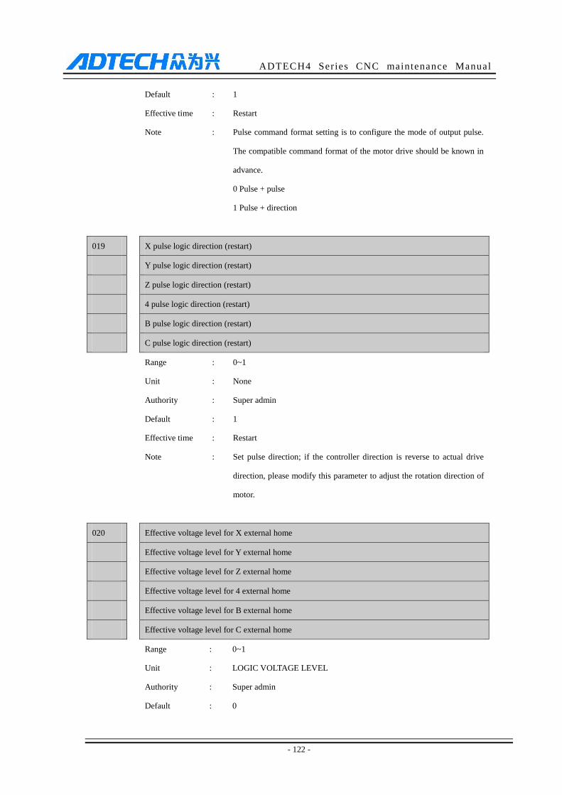
ADTECH4 Series CNC maintenance Manual
- 122 -
Default : 1
Effective time : Restart
Note : Pulse command format setting is to configure the mode of output pulse.
The compatible command format of the motor drive should be known in
advance.
0 Pulse + pulse
1 Pulse + direction
019 X pulse logic direction (restart)
Y pulse logic direction (restart)
Z pulse logic direction (restart)
4 pulse logic direction (restart)
B pulse logic direction (restart)
C pulse logic direction (restart)
Range : 0~1
Unit : None
Authority : Super admin
Default : 1
Effective time : Restart
Note : Set pulse direction; if the controller direction is reverse to actual drive
direction, please modify this parameter to adjust the rotation direction of
motor.
020 Effective voltage level for X external home
Effective voltage level for Y external home
Effective voltage level for Z external home
Effective voltage level for 4 external home
Effective voltage level for B external home
Effective voltage level for C external home
Range : 0~1
Unit : LOGIC VOLTAGE LEVEL
Authority : Super admin
Default : 0
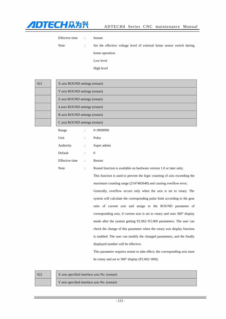
ADTECH4 Series CNC maintenance Manual
- 123 -
Effective time : Instant
Note : Set the effective voltage level of external home sensor switch during
home operation.
Low level
High level
021 X axis ROUND settings (restart)
Y axis ROUND settings (restart)
Z axis ROUND settings (restart)
4 axes ROUND settings (restart)
B axis ROUND settings (restart)
C axis ROUND settings (restart)
Range : 0~9999999
Unit : Pulse
Authority : Super admin
Default : 0
Effective time : Restart
Note : Round function is available on hardware version 1.0 or later only;
This function is used to prevent the logic counting of axis exceeding the
maximum counting range (2147483648) and causing overflow error;
Generally, overflow occurs only when the axis is set to rotary. The
system will calculate the corresponding pulse limit according to the gear
ratio of current axis and assign to the ROUND parameter of
corresponding axis, if current axis is set to rotary and uses 360° display
mode after the system getting P2.062~P2.069 parameters. The user can
check the change of this parameter when the rotary axis display function
is enabled. The user can modify the changed parameters, and the finally
displayed number will be effective.
This parameter requires restart to take effect; the corresponding axis must
be rotary and set to 360° display (P2.062~069);
022 X axis specified interface axis No. (restart)
Y axis specified interface axis No. (restart)
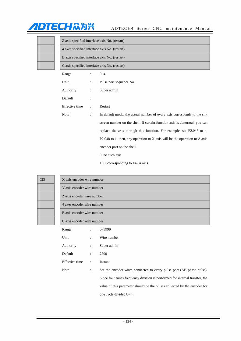
ADTECH4 Series CNC maintenance Manual
- 124 -
Z axis specified interface axis No. (restart)
4 axes specified interface axis No. (restart)
B axis specified interface axis No. (restart)
C axis specified interface axis No. (restart)
Range : 0~4
Unit : Pulse port sequence No.
Authority : Super admin
Default :
Effective time : Restart
Note : In default mode, the actual number of every axis corresponds to the silk
screen number on the shell. If certain function axis is abnormal, you can
replace the axis through this function. For example, set P2.045 to 4,
P2.048 to 1, then, any operation to X axis will be the operation to A axis
encoder port on the shell.
0: no such axis
1~6: corresponding to 1#-6# axis
023 X axis encoder wire number
Y axis encoder wire number
Z axis encoder wire number
4 axes encoder wire number
B axis encoder wire number
C axis encoder wire number
Range : 0~9999
Unit : Wire number
Authority : Super admin
Default : 2500
Effective time : Instant
Note : Set the encoder wires connected to every pulse port (AB phase pulse).
Since four times frequency division is performed for internal transfer, the
value of this parameter should be the pulses collected by the encoder for
one cycle divided by 4.
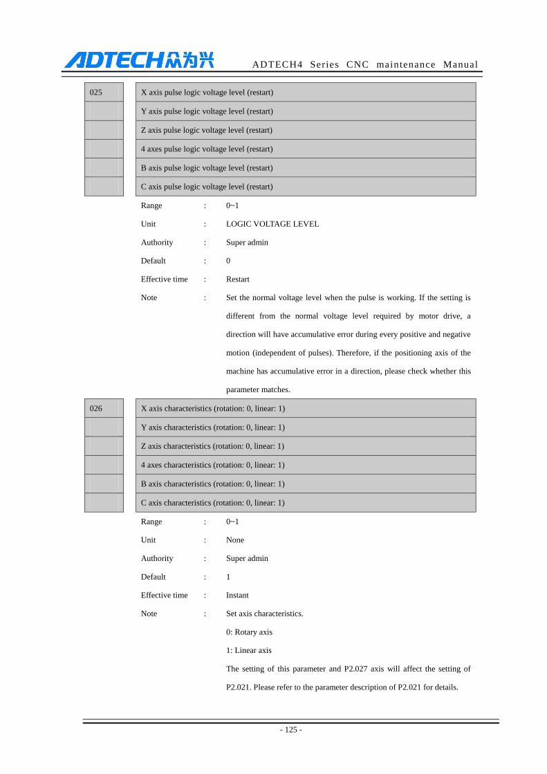
ADTECH4 Series CNC maintenance Manual
- 125 -
025 X axis pulse logic voltage level (restart)
Y axis pulse logic voltage level (restart)
Z axis pulse logic voltage level (restart)
4 axes pulse logic voltage level (restart)
B axis pulse logic voltage level (restart)
C axis pulse logic voltage level (restart)
Range : 0~1
Unit : LOGIC VOLTAGE LEVEL
Authority : Super admin
Default : 0
Effective time : Restart
Note : Set the normal voltage level when the pulse is working. If the setting is
different from the normal voltage level required by motor drive, a
direction will have accumulative error during every positive and negative
motion (independent of pulses). Therefore, if the positioning axis of the
machine has accumulative error in a direction, please check whether this
parameter matches.
026 X axis characteristics (rotation: 0, linear: 1)
Y axis characteristics (rotation: 0, linear: 1)
Z axis characteristics (rotation: 0, linear: 1)
4 axes characteristics (rotation: 0, linear: 1)
B axis characteristics (rotation: 0, linear: 1)
C axis characteristics (rotation: 0, linear: 1)
Range : 0~1
Unit : None
Authority : Super admin
Default : 1
Effective time : Instant
Note : Set axis characteristics.
0: Rotary axis
1: Linear axis
The setting of this parameter and P2.027 axis will affect the setting of
P2.021. Please refer to the parameter description of P2.021 for details.

ADTECH4 Series CNC maintenance Manual
- 126 -
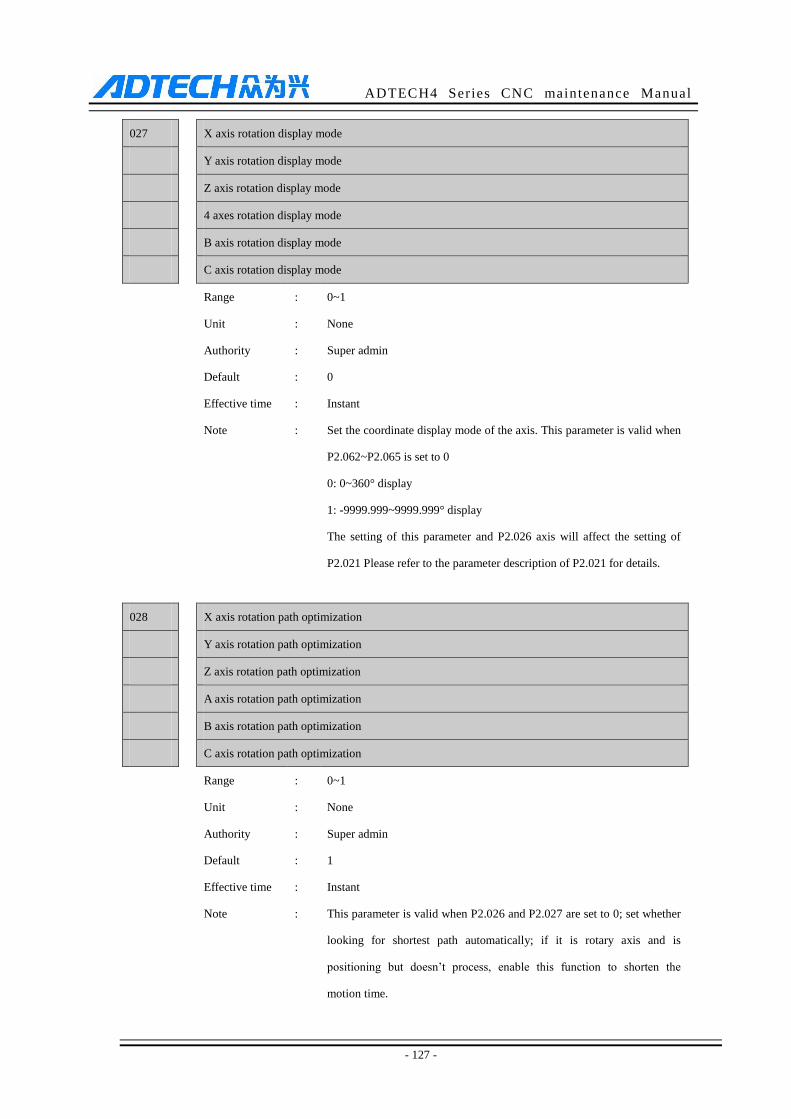
ADTECH4 Series CNC maintenance Manual
- 127 -
027 X axis rotation display mode
Y axis rotation display mode
Z axis rotation display mode
4 axes rotation display mode
B axis rotation display mode
C axis rotation display mode
Range : 0~1
Unit : None
Authority : Super admin
Default : 0
Effective time : Instant
Note : Set the coordinate display mode of the axis. This parameter is valid when
P2.062~P2.065 is set to 0
0: 0~360° display
1: -9999.999~9999.999° display
The setting of this parameter and P2.026 axis will affect the setting of
P2.021 Please refer to the parameter description of P2.021 for details.
028 X axis rotation path optimization
Y axis rotation path optimization
Z axis rotation path optimization
A axis rotation path optimization
B axis rotation path optimization
C axis rotation path optimization
Range : 0~1
Unit : None
Authority : Super admin
Default : 1
Effective time : Instant
Note : This parameter is valid when P2.026 and P2.027 are set to 0; set whether
looking for shortest path automatically; if it is rotary axis and is
positioning but doesn’t process, enable this function to shorten the
motion time.
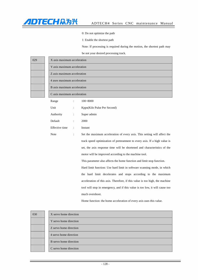
ADTECH4 Series CNC maintenance Manual
- 128 -
0: Do not optimize the path
1: Enable the shortest path
Note: If processing is required during the motion, the shortest path may
be not your desired processing track.
029 X axis maximum acceleration
Y axis maximum acceleration
Z axis maximum acceleration
4 axes maximum acceleration
B axis maximum acceleration
C axis maximum acceleration
Range : 100~8000
Unit : Kpps(Kilo Pulse Per Second)
Authority : Super admin
Default : 2000
Effective time : Instant
Note : Set the maximum acceleration of every axis. This setting will affect the
track speed optimization of pretreatment to every axis. If a high value is
set, the axis response time will be shortened and characteristics of the
motor will be improved according to the machine tool.
This parameter also affects the home function and limit stop function.
Hard limit function: Use hard limit in software scanning mode, in which
the hard limit decelerates and stops according to the maximum
acceleration of this axis. Therefore, if this value is too high, the machine
tool will stop in emergency, and if this value is too low, it will cause too
much overshoot.
Home function: the home acceleration of every axis uses this value.
030 X servo home direction
Y servo home direction
Z servo home direction
4 servo home direction
B servo home direction
C servo home direction
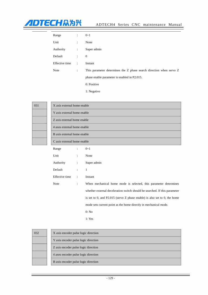
ADTECH4 Series CNC maintenance Manual
- 129 -
Range : 0~1
Unit : None
Authority : Super admin
Default : 0
Effective time : Instant
Note : This parameter determines the Z phase search direction when servo Z
phase enable parameter is enabled in P2.015.
0: Positive
1: Negative
031 X axis external home enable
Y axis external home enable
Z axis external home enable
4 axes external home enable
B axis external home enable
C axis external home enable
Range : 0~1
Unit : None
Authority : Super admin
Default : 1
Effective time : Instant
Note : When mechanical home mode is selected, this parameter determines
whether external deceleration switch should be searched. If this parameter
is set to 0, and P2.015 (servo Z phase enable) is also set to 0, the home
mode sets current point as the home directly in mechanical mode.
0: No
1: Yes
032 X axis encoder pulse logic direction
Y axis encoder pulse logic direction
Z axis encoder pulse logic direction
4 axes encoder pulse logic direction
B axis encoder pulse logic direction
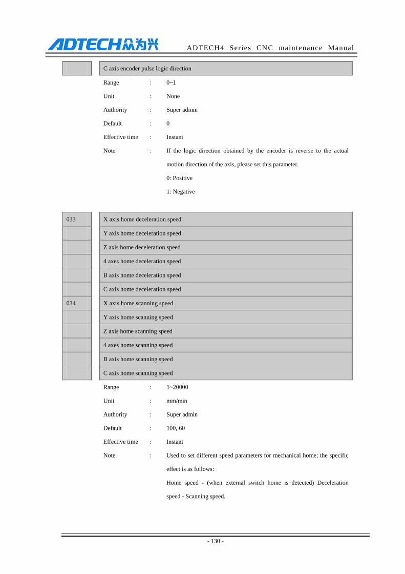
ADTECH4 Series CNC maintenance Manual
- 130 -
C axis encoder pulse logic direction
Range : 0~1
Unit : None
Authority : Super admin
Default : 0
Effective time : Instant
Note : If the logic direction obtained by the encoder is reverse to the actual
motion direction of the axis, please set this parameter.
0: Positive
1: Negative
033 X axis home deceleration speed
Y axis home deceleration speed
Z axis home deceleration speed
4 axes home deceleration speed
B axis home deceleration speed
C axis home deceleration speed
034 X axis home scanning speed
Y axis home scanning speed
Z axis home scanning speed
4 axes home scanning speed
B axis home scanning speed
C axis home scanning speed
Range : 1~20000
Unit : mm/min
Authority : Super admin
Default : 100, 60
Effective time : Instant
Note : Used to set different speed parameters for mechanical home; the specific
effect is as follows:
Home speed - (when external switch home is detected) Deceleration
speed - Scanning speed.
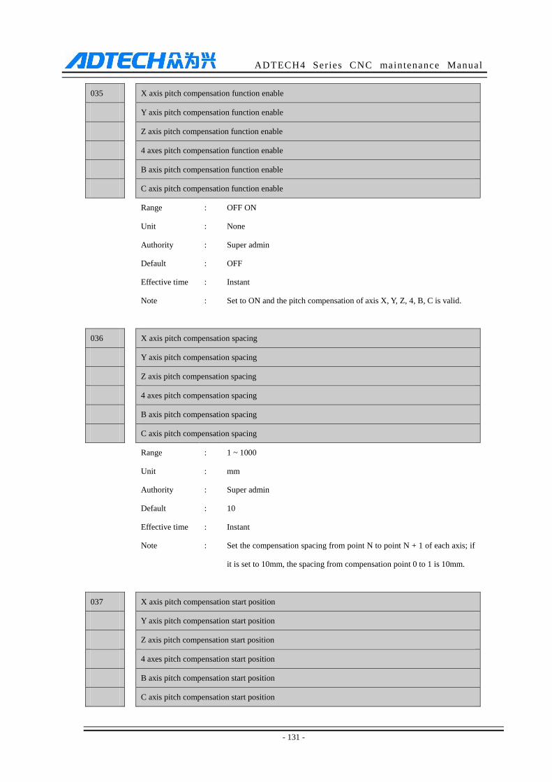
ADTECH4 Series CNC maintenance Manual
- 131 -
035 X axis pitch compensation function enable
Y axis pitch compensation function enable
Z axis pitch compensation function enable
4 axes pitch compensation function enable
B axis pitch compensation function enable
C axis pitch compensation function enable
Range : OFF ON
Unit : None
Authority : Super admin
Default : OFF
Effective time : Instant
Note : Set to ON and the pitch compensation of axis X, Y, Z, 4, B, C is valid.
036 X axis pitch compensation spacing
Y axis pitch compensation spacing
Z axis pitch compensation spacing
4 axes pitch compensation spacing
B axis pitch compensation spacing
C axis pitch compensation spacing
Range : 1 ~ 1000
Unit : mm
Authority : Super admin
Default : 10
Effective time : Instant
Note : Set the compensation spacing from point N to point N + 1 of each axis; if
it is set to 10mm, the spacing from compensation point 0 to 1 is 10mm.
037 X axis pitch compensation start position
Y axis pitch compensation start position
Z axis pitch compensation start position
4 axes pitch compensation start position
B axis pitch compensation start position
C axis pitch compensation start position
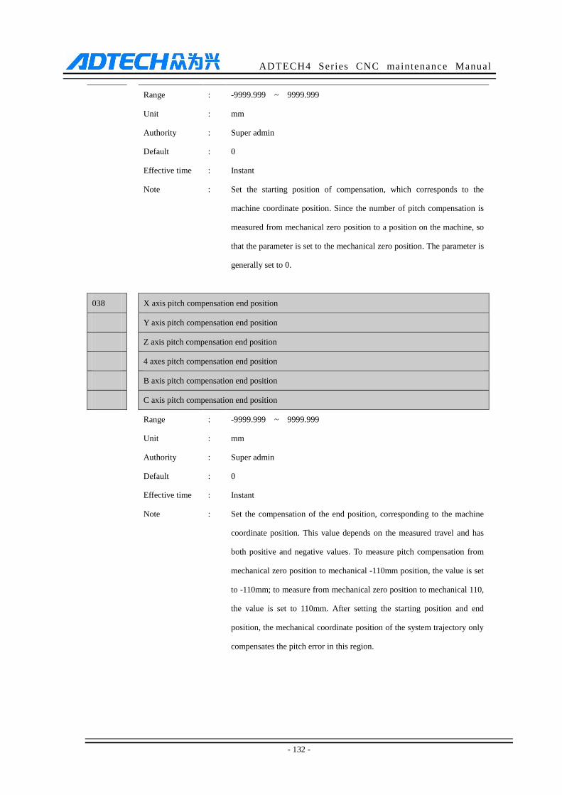
ADTECH4 Series CNC maintenance Manual
- 132 -
Range : -9999.999 ~ 9999.999
Unit : mm
Authority : Super admin
Default : 0
Effective time : Instant
Note : Set the starting position of compensation, which corresponds to the
machine coordinate position. Since the number of pitch compensation is
measured from mechanical zero position to a position on the machine, so
that the parameter is set to the mechanical zero position. The parameter is
generally set to 0.
038 X axis pitch compensation end position
Y axis pitch compensation end position
Z axis pitch compensation end position
4 axes pitch compensation end position
B axis pitch compensation end position
C axis pitch compensation end position
Range : -9999.999 ~ 9999.999
Unit : mm
Authority : Super admin
Default : 0
Effective time : Instant
Note : Set the compensation of the end position, corresponding to the machine
coordinate position. This value depends on the measured travel and has
both positive and negative values. To measure pitch compensation from
mechanical zero position to mechanical -110mm position, the value is set
to -110mm; to measure from mechanical zero position to mechanical 110,
the value is set to 110mm. After setting the starting position and end
position, the mechanical coordinate position of the system trajectory only
compensates the pitch error in this region.
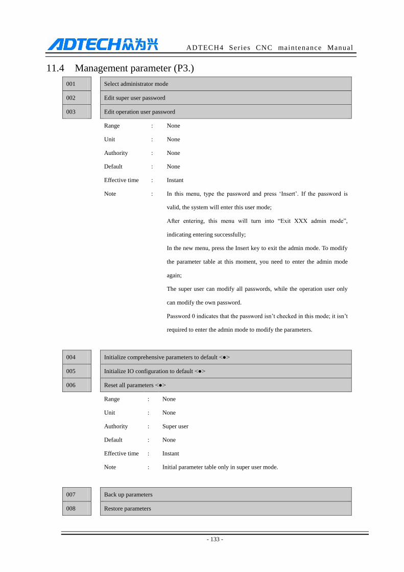
ADTECH4 Series CNC maintenance Manual
- 133 -
11.4 Management parameter (P3.)
001 Select administrator mode
002 Edit super user password
003 Edit operation user password
Range : None
Unit : None
Authority : None
Default : None
Effective time : Instant
Note : In this menu, type the password and press ‘Insert’. If the password is
valid, the system will enter this user mode;
After entering, this menu will turn into “Exit XXX admin mode”,
indicating entering successfully;
In the new menu, press the Insert key to exit the admin mode. To modify
the parameter table at this moment, you need to enter the admin mode
again;
The super user can modify all passwords, while the operation user only
can modify the own password.
Password 0 indicates that the password isn’t checked in this mode; it isn’t
required to enter the admin mode to modify the parameters.
004 Initialize comprehensive parameters to default <●>
005 Initialize IO configuration to default <●>
006 Reset all parameters <●>
Range : None
Unit : None
Authority : Super user
Default : None
Effective time : Instant
Note : Initial parameter table only in super user mode.
007 Back up parameters
008 Restore parameters
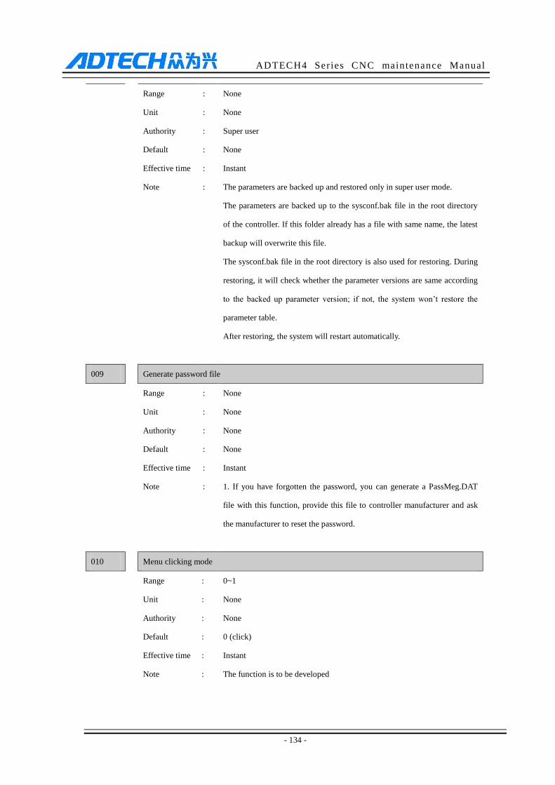
ADTECH4 Series CNC maintenance Manual
- 134 -
Range : None
Unit : None
Authority : Super user
Default : None
Effective time : Instant
Note : The parameters are backed up and restored only in super user mode.
The parameters are backed up to the sysconf.bak file in the root directory
of the controller. If this folder already has a file with same name, the latest
backup will overwrite this file.
The sysconf.bak file in the root directory is also used for restoring. During
restoring, it will check whether the parameter versions are same according
to the backed up parameter version; if not, the system won’t restore the
parameter table.
After restoring, the system will restart automatically.
009 Generate password file
Range : None
Unit : None
Authority : None
Default : None
Effective time : Instant
Note : 1. If you have forgotten the password, you can generate a PassMeg.DAT
file with this function, provide this file to controller manufacturer and ask
the manufacturer to reset the password.
010 Menu clicking mode
Range : 0~1
Unit : None
Authority : None
Default : 0 (click)
Effective time : Instant
Note : The function is to be developed
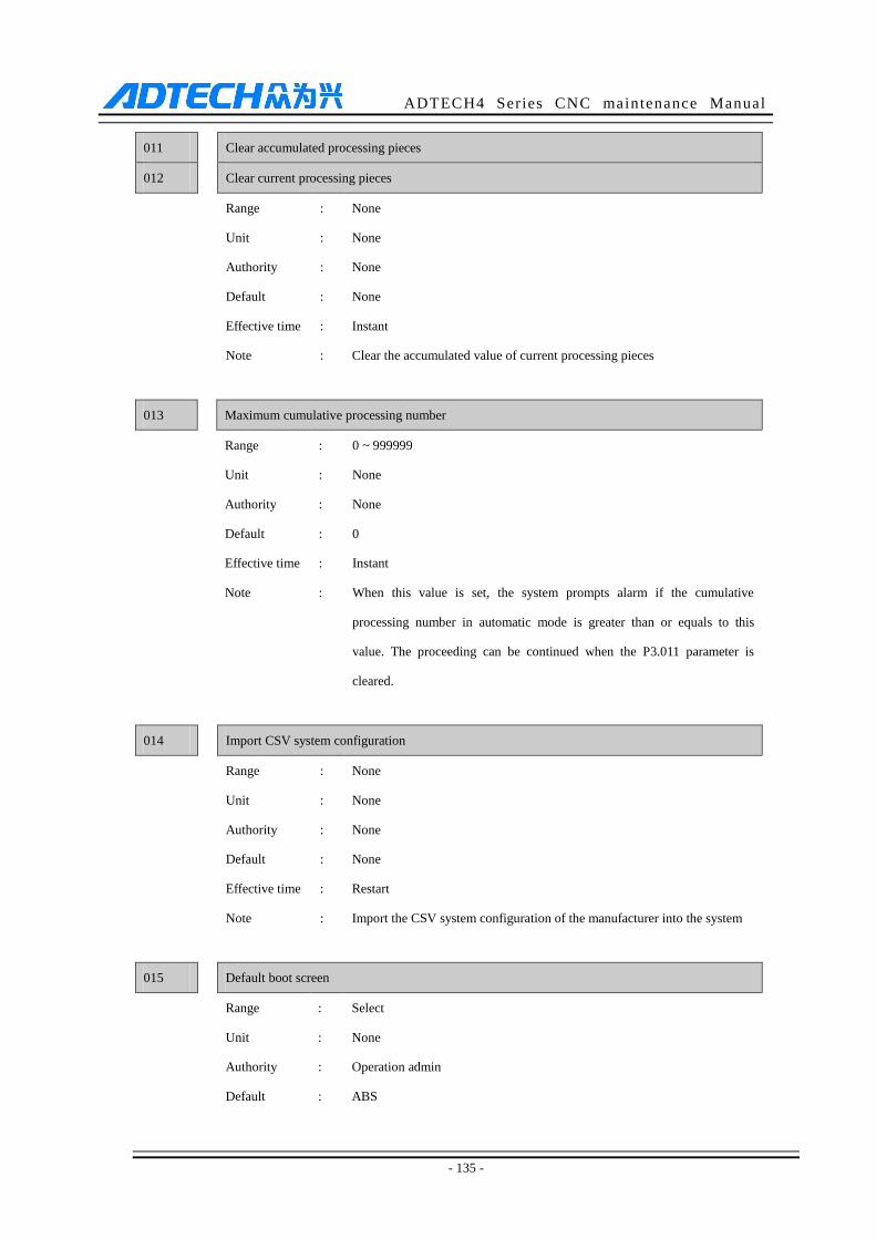
ADTECH4 Series CNC maintenance Manual
- 135 -
011 Clear accumulated processing pieces
012 Clear current processing pieces
Range : None
Unit : None
Authority : None
Default : None
Effective time : Instant
Note : Clear the accumulated value of current processing pieces
013 Maximum cumulative processing number
Range : 0 ~ 999999
Unit : None
Authority : None
Default : 0
Effective time : Instant
Note : When this value is set, the system prompts alarm if the cumulative
processing number in automatic mode is greater than or equals to this
value. The proceeding can be continued when the P3.011 parameter is
cleared.
014 Import CSV system configuration
Range : None
Unit : None
Authority : None
Default : None
Effective time : Restart
Note : Import the CSV system configuration of the manufacturer into the system
015 Default boot screen
Range : Select
Unit : None
Authority : Operation admin
Default : ABS
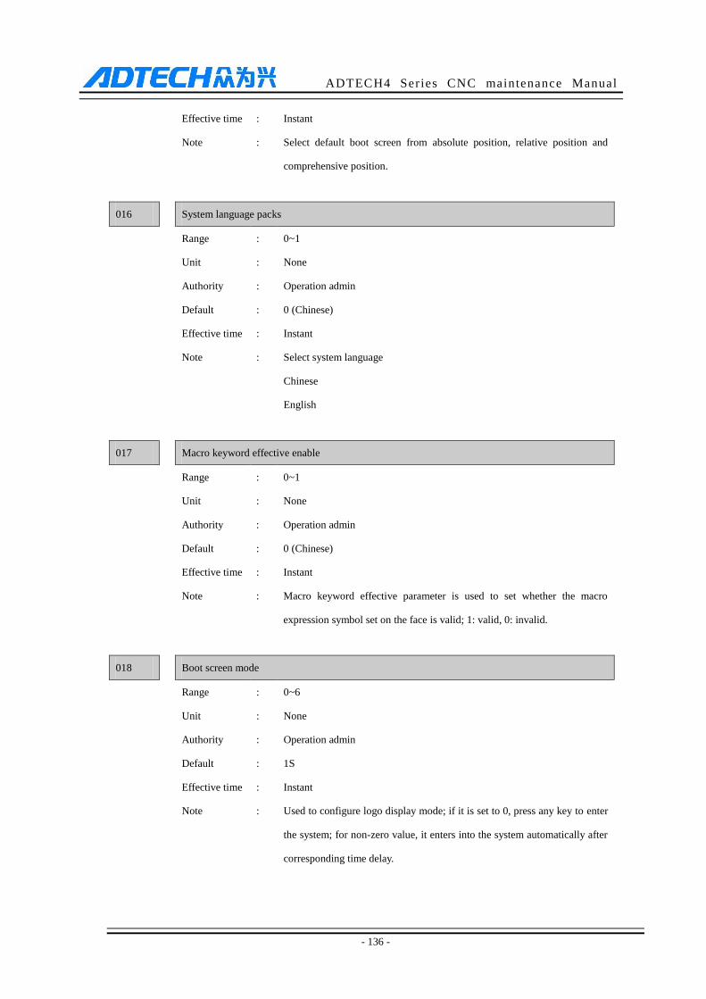
ADTECH4 Series CNC maintenance Manual
- 136 -
Effective time : Instant
Note : Select default boot screen from absolute position, relative position and
comprehensive position.
016 System language packs
Range : 0~1
Unit : None
Authority : Operation admin
Default : 0 (Chinese)
Effective time : Instant
Note : Select system language
Chinese
English
017 Macro keyword effective enable
Range : 0~1
Unit : None
Authority : Operation admin
Default : 0 (Chinese)
Effective time : Instant
Note : Macro keyword effective parameter is used to set whether the macro
expression symbol set on the face is valid; 1: valid, 0: invalid.
018 Boot screen mode
Range : 0~6
Unit : None
Authority : Operation admin
Default : 1S
Effective time : Instant
Note : Used to configure logo display mode; if it is set to 0, press any key to enter
the system; for non-zero value, it enters into the system automatically after
corresponding time delay.

ADTECH4 Series CNC maintenance Manual
- 137 -
019 System display axis setting (bit)
Range :
Unit : None
Authority : Super user
Default : XYZ
Effective time : Instant
Note : Used to configure the display axis of current system, and different display
combinations are available.
This configuration only determines the content of the interface. If the axis
function of the hardware exists, it still can output axis control during
programming, but the axis status won’t be displayed. The status such as
axis limit and alarm will be ignored.
020 System debugging info enable
Range : 0~1
Unit : None
Authority : Super user
Default : OFF/0
Effective time : Instant
Note : Used to configure whether RS232 of current system outputs debugging
information during running.
This parameter is dedicated for programmers, and users are not
recommended to enable this parameter.
If debugging information is enabled, the system performance will
deteriorate, so that it is disabled in the normal process.
If networking is enabled, this feature must be turned off, or else the
networking will crash.
021 Axis control composite key enable
Range : 0~1
Unit : None
Authority : Super user
Default : ON/1
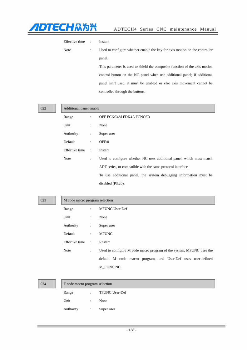
ADTECH4 Series CNC maintenance Manual
- 138 -
Effective time : Instant
Note : Used to configure whether enable the key for axis motion on the controller
panel.
This parameter is used to shield the composite function of the axis motion
control button on the NC panel when use additional panel; if additional
panel isn’t used, it must be enabled or else axis movement cannot be
controlled through the buttons.
022 Additional panel enable
Range : OFF FCNC4M FDK4A FCNC6D
Unit : None
Authority : Super user
Default : OFF/0
Effective time : Instant
Note : Used to configure whether NC uses additional panel, which must match
ADT series, or compatible with the same protocol interface.
To use additional panel, the system debugging information must be
disabled (P3.20).
023 M code macro program selection
Range : MFUNC User-Def
Unit : None
Authority : Super user
Default : MFUNC
Effective time : Restart
Note : Used to configure M code macro program of the system, MFUNC uses the
default M code macro program, and User-Def uses user-defined
M_FUNC.NC.
024 T code macro program selection
Range : TFUNC User-Def
Unit : None
Authority : Super user
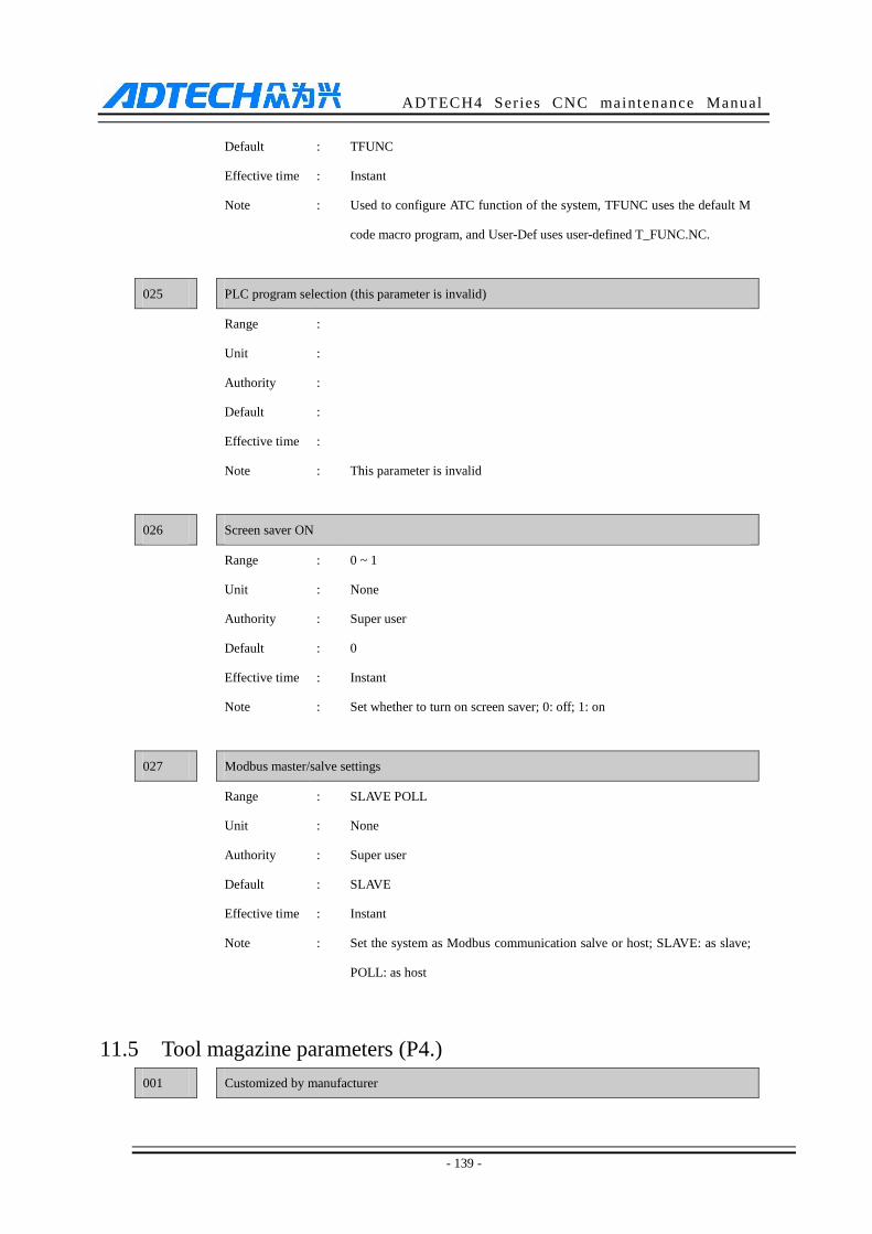
ADTECH4 Series CNC maintenance Manual
- 139 -
Default : TFUNC
Effective time : Instant
Note : Used to configure ATC function of the system, TFUNC uses the default M
code macro program, and User-Def uses user-defined T_FUNC.NC.
025 PLC program selection (this parameter is invalid)
Range :
Unit :
Authority :
Default :
Effective time :
Note : This parameter is invalid
026 Screen saver ON
Range : 0 ~ 1
Unit : None
Authority : Super user
Default : 0
Effective time : Instant
Note : Set whether to turn on screen saver; 0: off; 1: on
027 Modbus master/salve settings
Range : SLAVE POLL
Unit : None
Authority : Super user
Default : SLAVE
Effective time : Instant
Note : Set the system as Modbus communication salve or host; SLAVE: as slave;
POLL: as host
11.5 Tool magazine parameters (P4.)
001 Customized by manufacturer
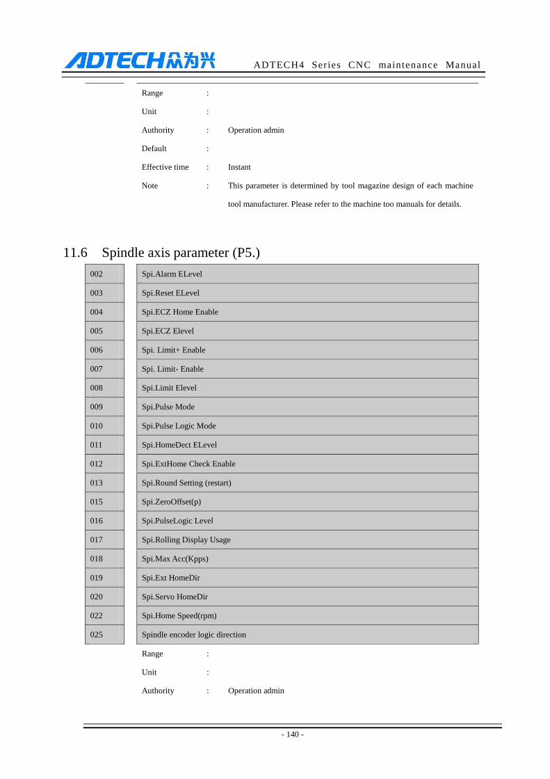
ADTECH4 Series CNC maintenance Manual
- 140 -
Range :
Unit :
Authority : Operation admin
Default :
Effective time : Instant
Note : This parameter is determined by tool magazine design of each machine
tool manufacturer. Please refer to the machine too manuals for details.
11.6 Spindle axis parameter (P5.)
002 Spi.Alarm ELevel
003 Spi.Reset ELevel
004 Spi.ECZ Home Enable
005 Spi.ECZ Elevel
006 Spi. Limit+ Enable
007 Spi. Limit- Enable
008 Spi.Limit Elevel
009 Spi.Pulse Mode
010 Spi.Pulse Logic Mode
011 Spi.HomeDect ELevel
012 Spi.ExtHome Check Enable
013 Spi.Round Setting (restart)
015 Spi.ZeroOffset(p)
016 Spi.PulseLogic Level
017 Spi.Rolling Display Usage
018 Spi.Max Acc(Kpps)
019 Spi.Ext HomeDir
020 Spi.Servo HomeDir
022
Spi.Home Speed(rpm)
025 Spindle encoder logic direction
Range :
Unit :
Authority : Operation admin

ADTECH4 Series CNC maintenance Manual
- 141 -
Default :
Effective time :
Note : Servo spindle axis parameters are same as common positioning axis
parameters. If only the spindle axis is controlled with servo port, you can
set the number according to axis parameters.
001 Spindle physical Assign Num (restart)
Range : 0~7
Unit : Pulse port sequence No.
Authority : Super admin
Default :
Effective time : Restart
Note : It is set to 0 by default, indicating that the spindle axis is in variable
frequency control mode, i.e. analog or gear position control mode. To use
servo spindle axis, a coding port is required (servo spindle axis must be
in position control mode); you can modify this parameter to specify the
function.
0: variable frequency spindle axis adjusted by analog
1~4: for CNC4640(20), corresponding to 1#-4# axis
7: for CNC4960(40), corresponding to independent spindle interface
Note: If a pulse port is specified as the function port of spindle axis, the
pulse port should be removed from previously corresponding function
axis number, or else the system will assign to spindle axis after restarted
and the original function axis will be invalid.
014 Spindle encoder bits
Range : 0~5000
Unit : None
Authority : Operation admin
Default : 2500
Effective time : Instant
Note : The received wire number of the encoder when the spindle axis rotates
one circle;

ADTECH4 Series CNC maintenance Manual
- 142 -
Same as common axis encoder, it can only receive AB phase pulse, and
thus the wire number of the encoder must be pulses of one circle divided
by 4.
This parameter will affect G74 and G84 tap instructions. Please set it
properly.
021 Spindle Max Speed
Range : 1~30000
Unit : None
Authority : Operation admin
Default : 24000
Effective time : Instant
Note : This setting is used to calculate the analog output of the controller, and
suppose that the analog of variable frequency control is in linear control
mode;
This method is to set the rotation to this parameter according to the
variable frequency rotation corresponding to analog 10V, and transfer the
rotation directly later, while the controller will output corresponding
analog voltage according to linear scale automatically.
023 Spindle Gear Numerator (CMR)
024 Spindle Gear Denominator (CMD)
Range : 1~65535
Unit : None
Authority : Operation admin
Default : 1
Effective time : Instant
Note : If the spindle axis has gear position, please set the hardware gear ratio to
this parameter, which hasn’t been used in standard version, but may be
used in certain special conditions.
026 Spindle axis on delay
Range : 0~10000
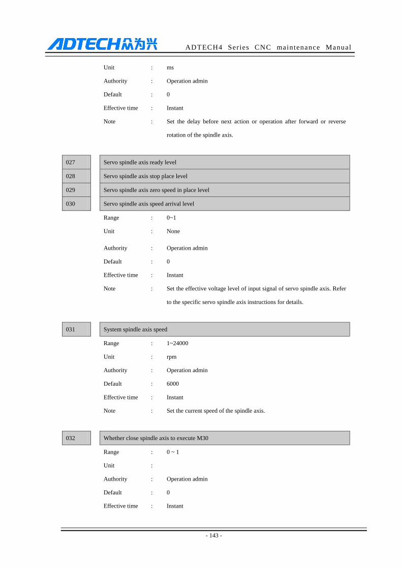
ADTECH4 Series CNC maintenance Manual
- 143 -
Unit : ms
Authority : Operation admin
Default : 0
Effective time : Instant
Note : Set the delay before next action or operation after forward or reverse
rotation of the spindle axis.
027 Servo spindle axis ready level
028
Servo spindle axis stop place level
029 Servo spindle axis zero speed in place level
030 Servo spindle axis speed arrival level
Range : 0~1
Unit : None
Authority : Operation admin
Default : 0
Effective time : Instant
Note : Set the effective voltage level of input signal of servo spindle axis. Refer
to the specific servo spindle axis instructions for details.
031 System spindle axis speed
Range : 1~24000
Unit : rpm
Authority : Operation admin
Default : 6000
Effective time : Instant
Note : Set the current speed of the spindle axis.
032 Whether close spindle axis to execute M30
Range : 0 ~ 1
Unit :
Authority : Operation admin
Default : 0
Effective time : Instant
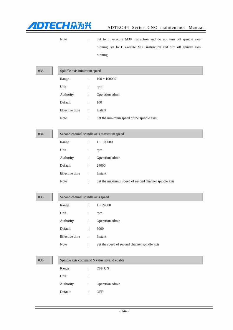
ADTECH4 Series CNC maintenance Manual
- 144 -
Note : Set to 0: execute M30 instruction and do not turn off spindle axis
running; set to 1: execute M30 instruction and turn off spindle axis
running.
033 Spindle axis minimum speed
Range : 100 ~ 100000
Unit : rpm
Authority : Operation admin
Default : 100
Effective time : Instant
Note : Set the minimum speed of the spindle axis
034 Second channel spindle axis maximum speed
Range : 1 ~ 100000
Unit : rpm
Authority : Operation admin
Default : 24000
Effective time : Instant
Note : Set the maximum speed of second channel spindle axis
035 Second channel spindle axis speed
Range : 1 ~ 24000
Unit : rpm
Authority : Operation admin
Default : 6000
Effective time : Instant
Note : Set the speed of second channel spindle axis
036 Spindle axis command S value invalid enable
Range : OFF ON
Unit :
Authority : Operation admin
Default : OFF
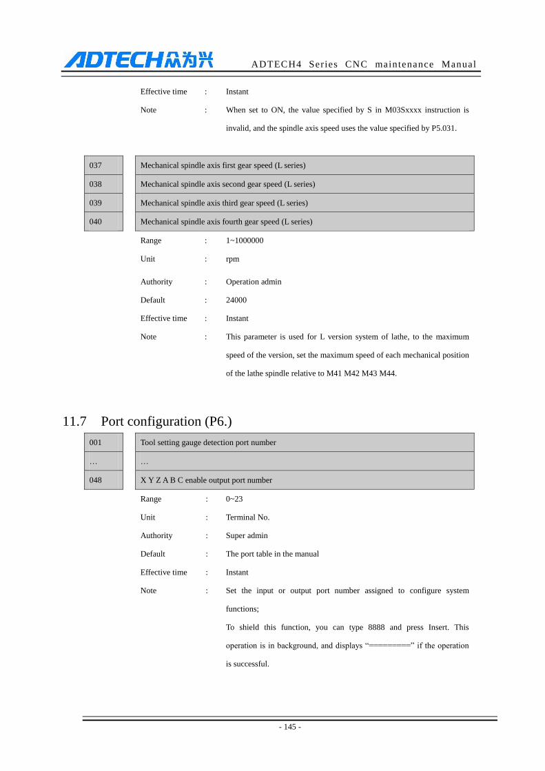
ADTECH4 Series CNC maintenance Manual
- 145 -
Effective time : Instant
Note : When set to ON, the value specified by S in M03Sxxxx instruction is
invalid, and the spindle axis speed uses the value specified by P5.031.
037 Mechanical spindle axis first gear speed (L series)
038
Mechanical spindle axis second gear speed (L series)
039 Mechanical spindle axis third gear speed (L series)
040 Mechanical spindle axis fourth gear speed (L series)
Range : 1~1000000
Unit : rpm
Authority : Operation admin
Default : 24000
Effective time : Instant
Note : This parameter is used for L version system of lathe, to the maximum
speed of the version, set the maximum speed of each mechanical position
of the lathe spindle relative to M41 M42 M43 M44.
11.7 Port configuration (P6.)
001 Tool setting gauge detection port number
… …
048 X Y Z A B C enable output port number
Range : 0~23
Unit : Terminal No.
Authority : Super admin
Default : The port table in the manual
Effective time : Instant
Note : Set the input or output port number assigned to configure system
functions;
To shield this function, you can type 8888 and press Insert. This
operation is in background, and displays “=========” if the operation
is successful.

ADTECH4 Series CNC maintenance Manual
- 146 -
049 Input detection effective voltage level 00 ~ 31
050 Input detection effective voltage level 32 ~ 63
051 Input detection effective voltage level 64 ~ 95
Range : 0x00000000~0xFFFFFFFF
Unit :
Authority : Super admin
Default : 0
Effective time : Instant
Note : Used to configure IO detection effective voltage level, 0: Low 1: High.
Use binary system to configure in positions.
For example: P6.050:10, is 00000000 00000000 00000000 00001010 in
binary system;
which indicates that among input ports IN32 ~ IN63, IN33 IN35 IO
detection effective voltage level is high, while other IO detection
effective voltage levels are low.
052 IO Conf in RESET 00~31
053 IO Conf in RESET 32~63
054 IO Conf in RESET 64~95
Range : 0x00000000~0xFFFFFFFF
Unit :
Authority : Super admin
Default : 0
Effective time : Instant
Note : Used to configure the IO that the system needs to reset when there is
alarm. 0: No; 1: Yes
Used to configure the IO signal that the system needs to reset when there
is alarm.
For example: P6.53:10, is 00000000 00000000 00000000 00001010 in
binary system;
which indicates that among OUT32 ~ OUT63, OUT33 is reset when the
system resets or alarms, OUT35 turns off, while other output ports are
not reset.
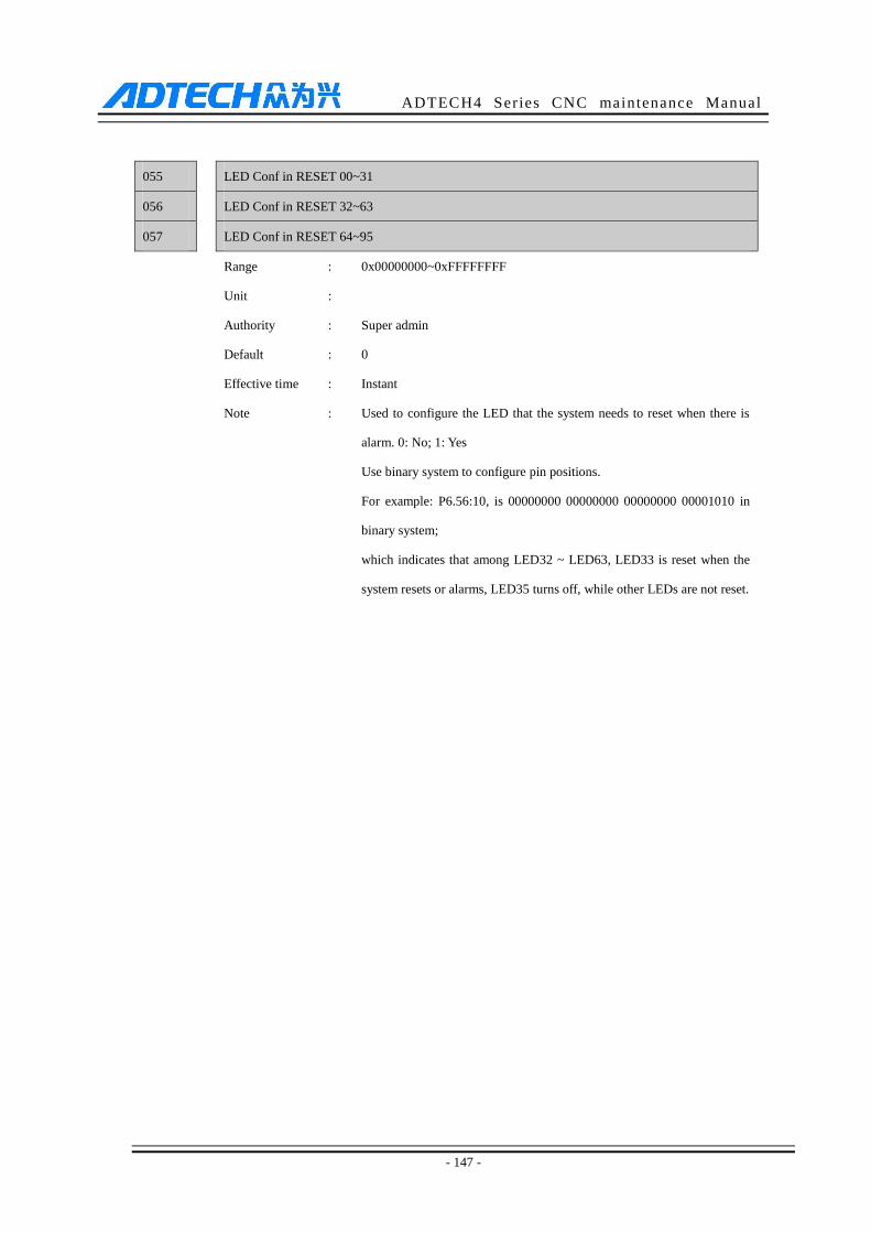
ADTECH4 Series CNC maintenance Manual
- 147 -
055 LED Conf in RESET 00~31
056 LED Conf in RESET 32~63
057 LED Conf in RESET 64~95
Range : 0x00000000~0xFFFFFFFF
Unit :
Authority : Super admin
Default : 0
Effective time : Instant
Note : Used to configure the LED that the system needs to reset when there is
alarm. 0: No; 1: Yes
Use binary system to configure pin positions.
For example: P6.56:10, is 00000000 00000000 00000000 00001010 in
binary system;
which indicates that among LED32 ~ LED63, LED33 is reset when the
system resets or alarms, LED35 turns off, while other LEDs are not reset.
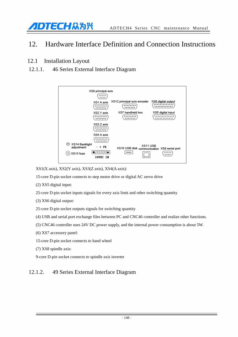
ADTECH4 Series CNC maintenance Manual
- 148 -
12. Hardware Interface Definition and Connection Instructions
12.1 Installation Layout
12.1.1. 46 Series External Interface Diagram
XS1(X axis), XS2(Y axis), XS3(Z axis), XS4(A axis):
15-core D-pin socket connects to step motor drive or digital AC servo drive
(2) XS5 digital input:
25-core D-pin socket inputs signals for every axis limit and other switching quantity
(3) XS6 digital output:
25-core D-pin socket outputs signals for switching quantity
(4) USB and serial port exchange files between PC and CNC46 controller and realize other functions.
(5) CNC46 controller uses 24V DC power supply, and the internal power consumption is about 5W.
(6) XS7 accessory panel:
15-core D-pin socket connects to hand wheel
(7) XS8 spindle axis:
9-core D-pin socket connects to spindle axis inverter
12.1.2. 49 Series External Interface Diagram
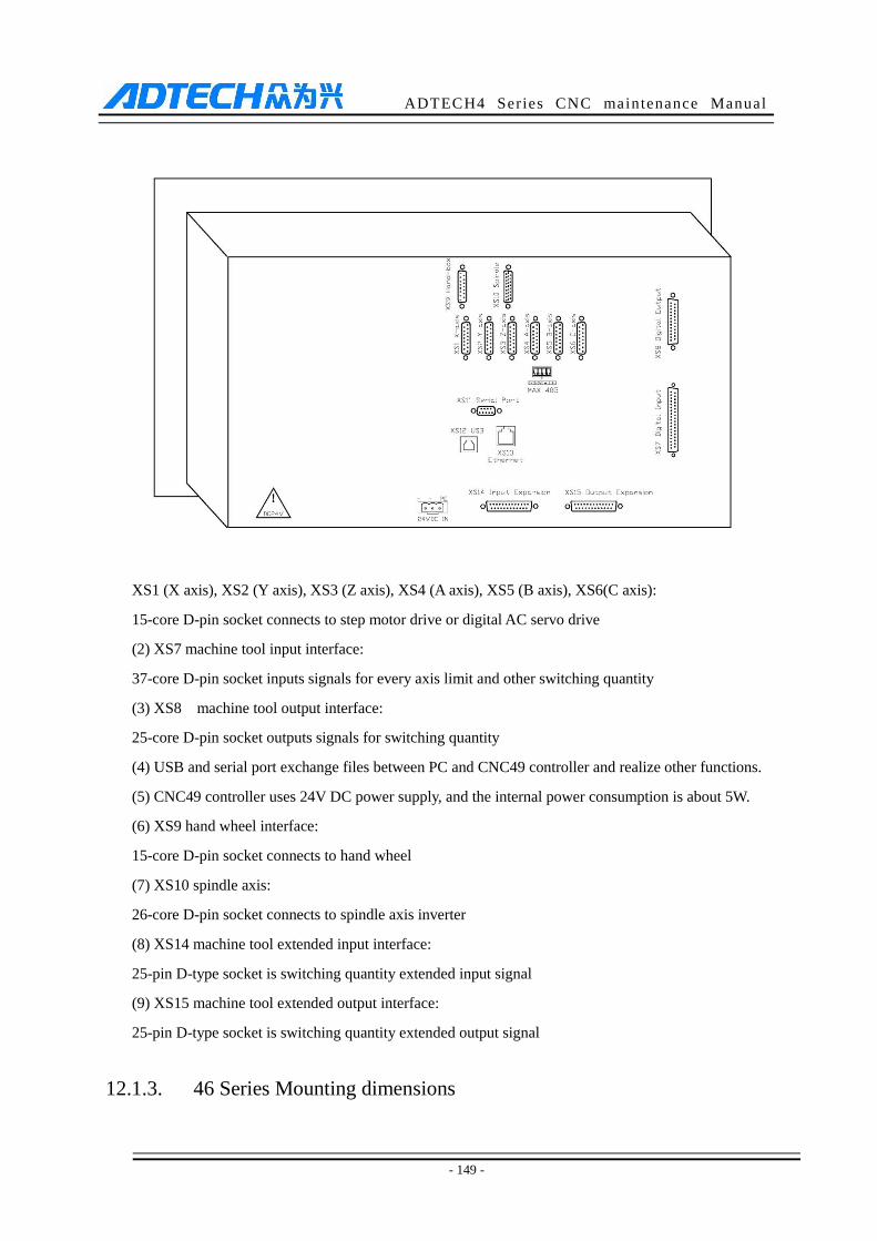
ADTECH4 Series CNC maintenance Manual
- 149 -
XS1 (X axis), XS2 (Y axis), XS3 (Z axis), XS4 (A axis), XS5 (B axis), XS6(C axis):
15-core D-pin socket connects to step motor drive or digital AC servo drive
(2) XS7 machine tool input interface:
37-core D-pin socket inputs signals for every axis limit and other switching quantity
(3) XS8 machine tool output interface:
25-core D-pin socket outputs signals for switching quantity
(4) USB and serial port exchange files between PC and CNC49 controller and realize other functions.
(5) CNC49 controller uses 24V DC power supply, and the internal power consumption is about 5W.
(6) XS9 hand wheel interface:
15-core D-pin socket connects to hand wheel
(7) XS10 spindle axis:
26-core D-pin socket connects to spindle axis inverter
(8) XS14 machine tool extended input interface:
25-pin D-type socket is switching quantity extended input signal
(9) XS15 machine tool extended output interface:
25-pin D-type socket is switching quantity extended output signal
12.1.3. 46 Series Mounting dimensions

ADTECH4 Series CNC maintenance Manual
- 150 -
12.1.4. 49 Series Mounting dimensions

ADTECH4 Series CNC maintenance Manual
- 151 -
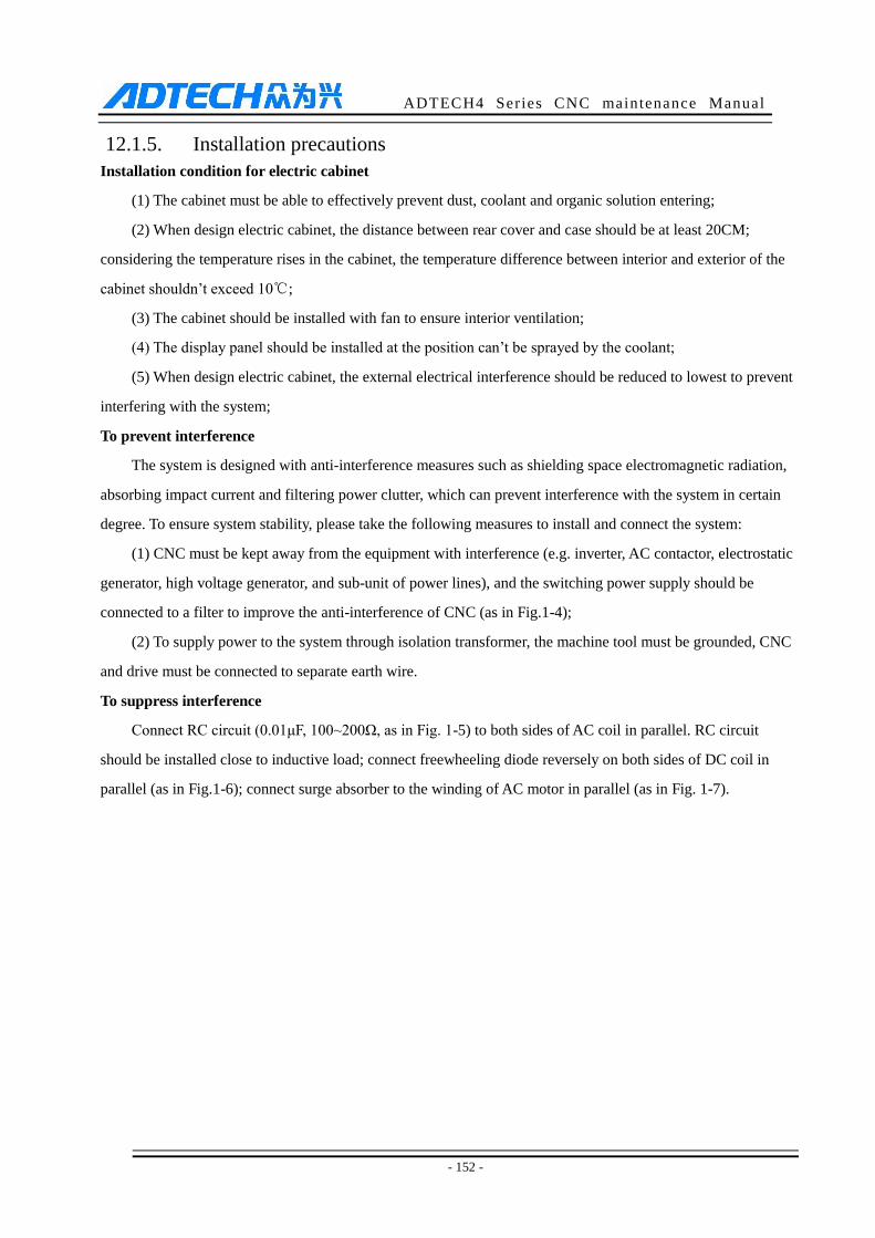
ADTECH4 Series CNC maintenance Manual
- 152 -
12.1.5. Installation precautions
Installation condition for electric cabinet
(1) The cabinet must be able to effectively prevent dust, coolant and organic solution entering;
(2) When design electric cabinet, the distance between rear cover and case should be at least 20CM;
considering the temperature rises in the cabinet, the temperature difference between interior and exterior of the
cabinet shouldn’t exceed 10℃;
(3) The cabinet should be installed with fan to ensure interior ventilation;
(4) The display panel should be installed at the position can’t be sprayed by the coolant;
(5) When design electric cabinet, the external electrical interference should be reduced to lowest to prevent
interfering with the system;
To prevent interference
The system is designed with anti-interference measures such as shielding space electromagnetic radiation,
absorbing impact current and filtering power clutter, which can prevent interference with the system in certain
degree. To ensure system stability, please take the following measures to install and connect the system:
(1) CNC must be kept away from the equipment with interference (e.g. inverter, AC contactor, electrostatic
generator, high voltage generator, and sub-unit of power lines), and the switching power supply should be
connected to a filter to improve the anti-interference of CNC (as in Fig.1-4);
(2) To supply power to the system through isolation transformer, the machine tool must be grounded, CNC
and drive must be connected to separate earth wire.
To suppress interference
Connect RC circuit (0.01μF, 100~200Ω, as in Fig. 1-5) to both sides of AC coil in parallel. RC circuit
should be installed close to inductive load; connect freewheeling diode reversely on both sides of DC coil in
parallel (as in Fig.1-6); connect surge absorber to the winding of AC motor in parallel (as in Fig. 1-7).
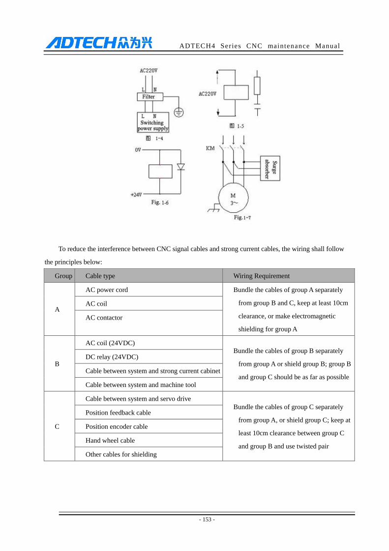
ADTECH4 Series CNC maintenance Manual
- 153 -
To reduce the interference between CNC signal cables and strong current cables, the wiring shall follow
the principles below:
Group Cable type Wiring Requirement
A
AC power cord Bundle the cables of group A separately
from group B and C, keep at least 10cm
clearance, or make electromagnetic
shielding for group A
AC coil
AC contactor
B
AC coil (24VDC) Bundle the cables of group B separately
from group A or shield group B; group B
and group C should be as far as possible
DC relay (24VDC)
Cable between system and strong current cabinet
Cable between system and machine tool
C
Cable between system and servo drive
Bundle the cables of group C separately
from group A, or shield group C; keep at
least 10cm clearance between group C
and group B and use twisted pair
Position feedback cable
Position encoder cable
Hand wheel cable
Other cables for shielding
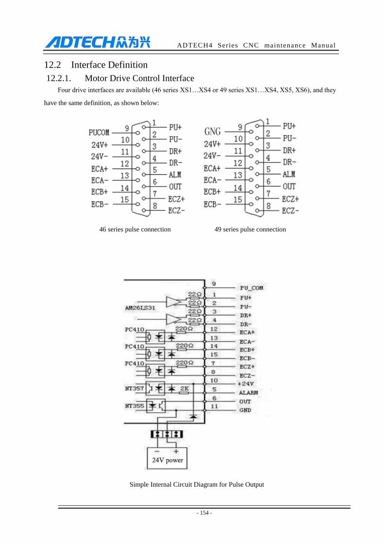
ADTECH4 Series CNC maintenance Manual
- 154 -
12.2 Interface Definition
12.2.1. Motor Drive Control Interface
Four drive interfaces are available (46 series XS1…XS4 or 49 series XS1…XS4, XS5, XS6), and they
have the same definition, as shown below:
Simple Internal Circuit Diagram for Pulse Output
46 series pulse connection 49 series pulse connection
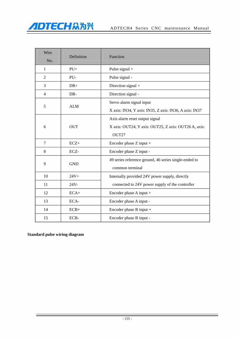
ADTECH4 Series CNC maintenance Manual
- 155 -
Wire
No. Definition Function
1 PU+ Pulse signal +
2 PU- Pulse signal -
3 DR+ Direction signal +
4 DR- Direction signal -
5 ALM Servo alarm signal input
X axis: IN34, Y axis: IN35, Z axis: IN36, A axis: IN37
6 OUT
Axis alarm reset output signal
X axis: OUT24, Y axis: OUT25, Z axis: OUT26 A, axis:
OUT27
7 ECZ+ Encoder phase Z input +
8 ECZ- Encoder phase Z input -
9 GND 49 series reference ground, 46 series single-ended to
common terminal
10 24V+ Internally provided 24V power supply, directly
connected to 24V power supply of the controller 11 24V-
12 ECA+ Encoder phase A input +
13 ECA- Encoder phase A input -
14 ECB+ Encoder phase B input +
15 ECB- Encoder phase B input -
Standard pulse wiring diagram

ADTECH4 Series CNC maintenance Manual
- 156 -
This wiring is suitable for 46 series and 49 series controller;
Step motor drive cable to differential input
Adtech CNC drive is for reference, all of which use differential input mode. This mode has strong
anti-interference and is recommended. Please refer to the figure below for the connection of CNC with step
motor drive and step motor
Step motor drive wiring diagram for single-ended input
Certain companies connect together the optocoupler input cathodes of step drives, i.e. common cathode
connection, which isn’t suitable for CNC controller. Common anode connection connects together the anodes of
optocoupler input. The wiring shall follow the figure below, and do not connect PU+ and DR+ together, or else
the pulse interface may be damaged.
XS1 … XS4 Pulse Interfaces Standard
Wiring

ADTECH4 Series CNC maintenance Manual
- 157 -
Wiring Diagram for Step Motor Drive with Common Anode Input
Servo motor drive wiring diagram (note: only applicable for 46 series controller)
Since differential connection is used in most cases, please refer to differential mode for the pulse
connection. Most servo drives require 12-24V power supply, and the 24V power provided by pin 10, 11 is
available. The specific connection depends on servo drive. Please contact us if you have any question.
Caution
Either two of PU+, PU-, DR+ and DR- shouldn’t be connected, or else the pulse interface may be damaged.
12.2.2. Digital input interface
The digital input interface contains the hard limit signal of every axis, and the definition follows:
Simple Internal Output Diagram for Digital Input Photoelectric Switch Wiring Diagram
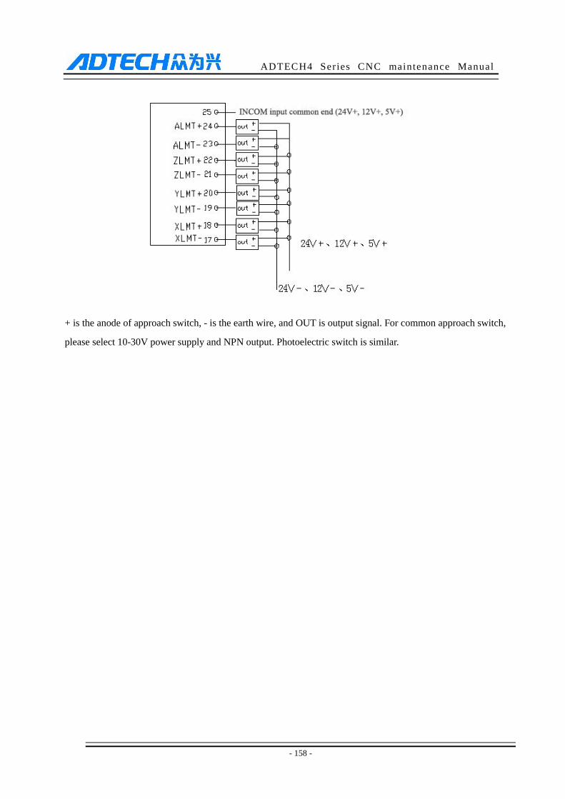
ADTECH4 Series CNC maintenance Manual
- 158 -
+ is the anode of approach switch, - is the earth wire, and OUT is output signal. For common approach switch,
please select 10-30V power supply and NPN output. Photoelectric switch is similar.
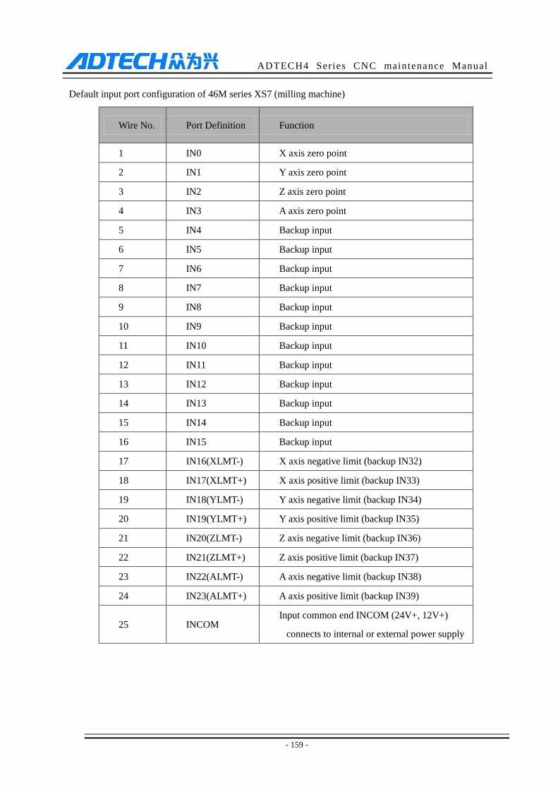
ADTECH4 Series CNC maintenance Manual
- 159 -
Default input port configuration of 46M series XS7 (milling machine)
Wire No. Port Definition Function
1 IN0 X axis zero point
2 IN1 Y axis zero point
3 IN2 Z axis zero point
4 IN3 A axis zero point
5 IN4 Backup input
6 IN5 Backup input
7 IN6 Backup input
8 IN7 Backup input
9 IN8 Backup input
10 IN9 Backup input
11 IN10 Backup input
12 IN11 Backup input
13 IN12 Backup input
14 IN13 Backup input
15 IN14 Backup input
16 IN15 Backup input
17 IN16(XLMT-) X axis negative limit (backup IN32)
18 IN17(XLMT+) X axis positive limit (backup IN33)
19 IN18(YLMT-) Y axis negative limit (backup IN34)
20 IN19(YLMT+) Y axis positive limit (backup IN35)
21 IN20(ZLMT-) Z axis negative limit (backup IN36)
22 IN21(ZLMT+) Z axis positive limit (backup IN37)
23 IN22(ALMT-) A axis negative limit (backup IN38)
24 IN23(ALMT+) A axis positive limit (backup IN39)
25 INCOM Input common end INCOM (24V+, 12V+)
connects to internal or external power supply
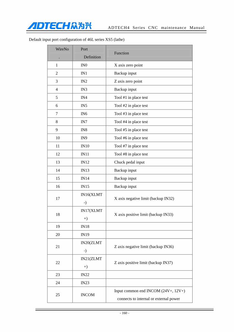
ADTECH4 Series CNC maintenance Manual
- 160 -
Default input port configuration of 46L series XS5 (lathe)
WireNo
.
Port
Definition Function
1 IN0 X axis zero point
2 IN1 Backup input
3 IN2 Z axis zero point
4 IN3 Backup input
5 IN4 Tool #1 in place test
6 IN5 Tool #2 in place test
7 IN6 Tool #3 in place test
8 IN7 Tool #4 in place test
9 IN8 Tool #5 in place test
10 IN9 Tool #6 in place test
11 IN10 Tool #7 in place test
12 IN11 Tool #8 in place test
13 IN12 Chuck pedal input
14 IN13 Backup input
15 IN14 Backup input
16 IN15 Backup input
17 IN16(XLMT
-) X axis negative limit (backup IN32)
18 IN17(XLMT
+) X axis positive limit (backup IN33)
19 IN18
20 IN19
21 IN20(ZLMT
-) Z axis negative limit (backup IN36)
22 IN21(ZLMT
+) Z axis positive limit (backup IN37)
23 IN22
24 IN23
25 INCOM Input common end INCOM (24V+, 12V+)
connects to internal or external power
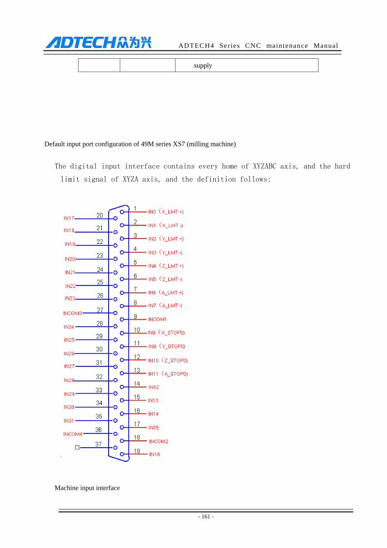
ADTECH4 Series CNC maintenance Manual
- 161 -
supply
Default input port configuration of 49M series XS7 (milling machine)
The digital input interface contains every home of XYZABC axis, and the hard
limit signal of XYZA axis, and the definition follows:
Machine input interface

ADTECH4 Series CNC maintenance Manual
- 162 -
37-pin
plug
wire
No.
4960(40)
definition Function
9163
definition
1 IN0 (X_LMT+) X axis positive
limit
IN00
2 IN1 (X_LMT-) X axis negative
limit
IN01
3 IN2 (Y_LMT+) Y axis positive
limit
IN02
4 IN3(Y_LMT-) Y axis negative
limit
IN03
5 IN4(Z_LMT+) Z axis positive
limit
IN04
6 IN5(Z_LMT-) Z axis negative
limit
IN05
7 IN6 (A_LMT+) A axis positive
limit
IN06
8 IN7 (A_LMT-) A axis negative
limit
IN07
9 INCOM1
Input common
terminal (24v+,
12v+)
+24V
10 IN8 (X_STOP0) X axis zero point IN08
11 IN9 (Y_STOP0) Y axis zero point IN09
12 IN10
(Z_STOP0) Z axis zero point
IN10
13 IN11
(A_STOP0) A axis zero point
IN11
14 IN12
(B_STOP0) B axis zero point
IN12
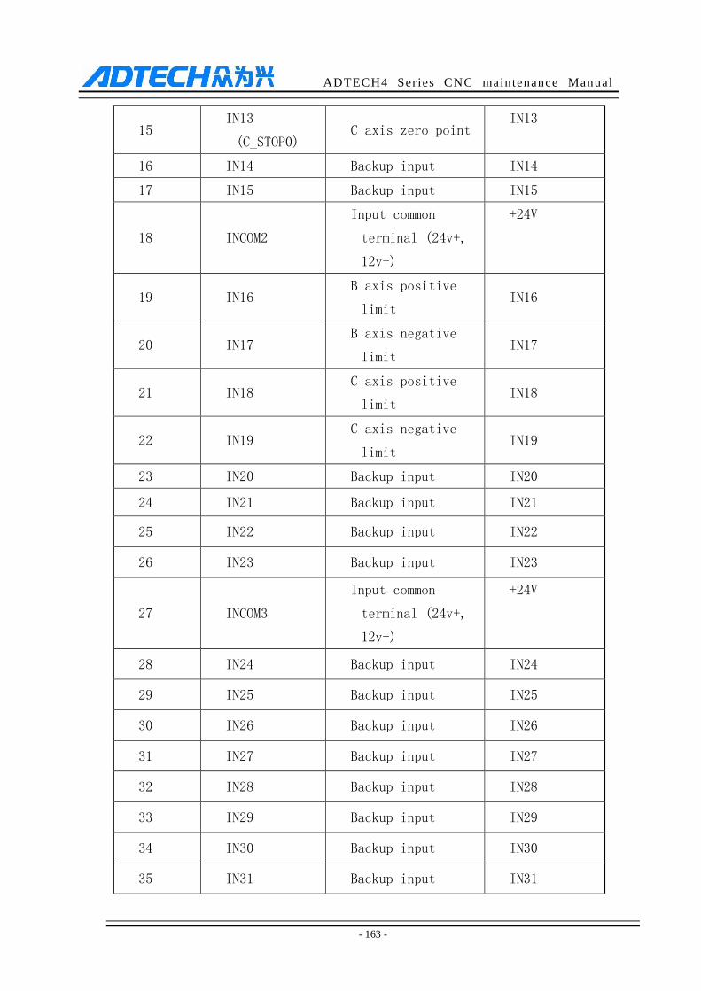
ADTECH4 Series CNC maintenance Manual
- 163 -
15 IN13
(C_STOP0) C axis zero point
IN13
16 IN14 Backup input IN14
17 IN15 Backup input IN15
18 INCOM2
Input common
terminal (24v+,
12v+)
+24V
19 IN16 B axis positive
limit IN16
20 IN17 B axis negative
limit IN17
21 IN18 C axis positive
limit IN18
22 IN19 C axis negative
limit IN19
23 IN20 Backup input IN20
24 IN21 Backup input IN21
25 IN22 Backup input IN22
26 IN23 Backup input IN23
27 INCOM3
Input common
terminal (24v+,
12v+)
+24V
28 IN24 Backup input IN24
29 IN25 Backup input IN25
30 IN26 Backup input IN26
31 IN27 Backup input IN27
32 IN28 Backup input IN28
33 IN29 Backup input IN29
34 IN30 Backup input IN30
35 IN31 Backup input IN31
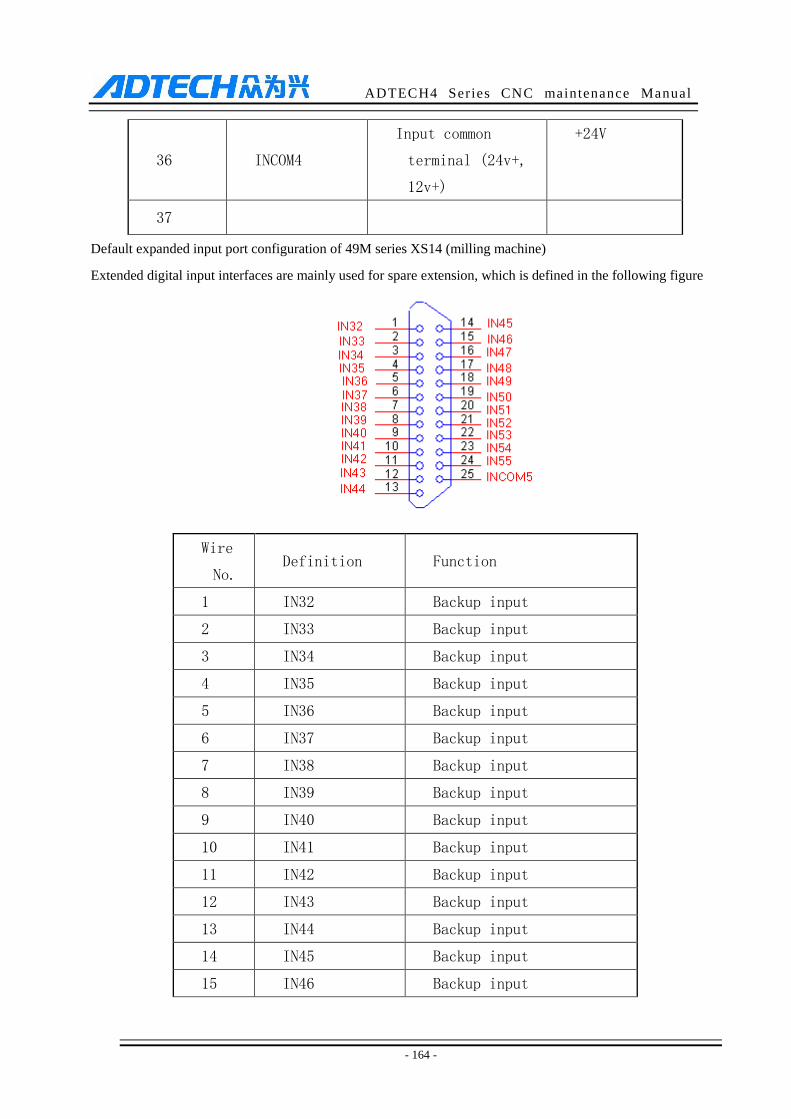
ADTECH4 Series CNC maintenance Manual
- 164 -
36 INCOM4
Input common
terminal (24v+,
12v+)
+24V
37
Default expanded input port configuration of 49M series XS14 (milling machine)
Extended digital input interfaces are mainly used for spare extension, which is defined in the following figure
Wire
No. Definition Function
1 IN32 Backup input
2 IN33 Backup input
3 IN34 Backup input
4 IN35 Backup input
5 IN36 Backup input
6 IN37 Backup input
7 IN38 Backup input
8 IN39 Backup input
9 IN40 Backup input
10 IN41 Backup input
11 IN42 Backup input
12 IN43 Backup input
13 IN44 Backup input
14 IN45 Backup input
15 IN46 Backup input
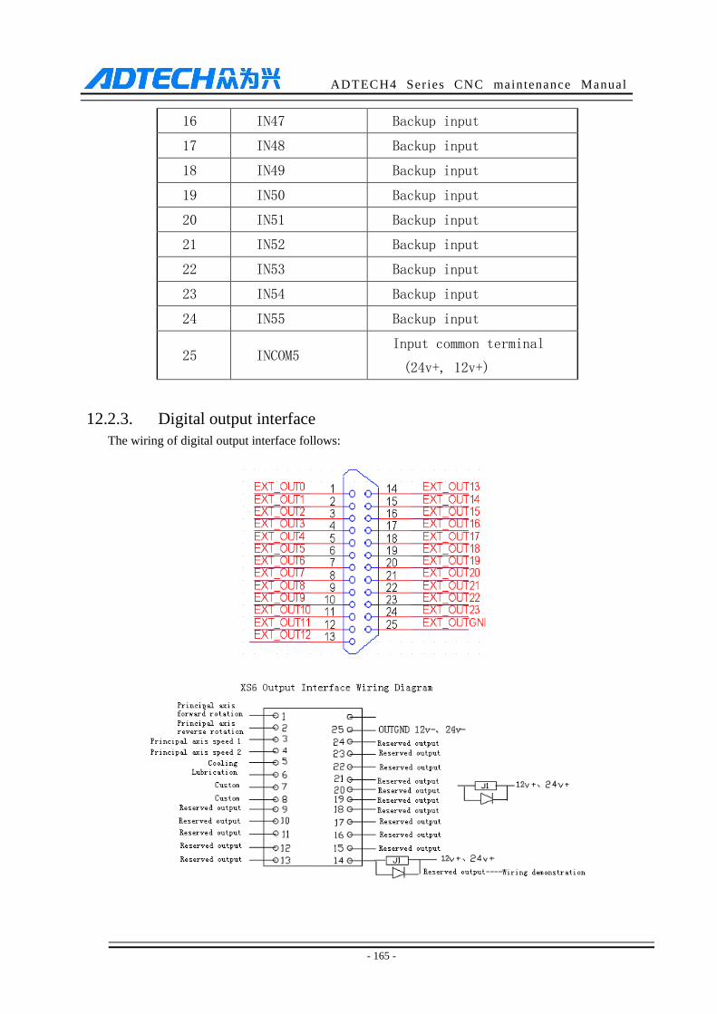
ADTECH4 Series CNC maintenance Manual
- 165 -
16 IN47 Backup input
17 IN48 Backup input
18 IN49 Backup input
19 IN50 Backup input
20 IN51 Backup input
21 IN52 Backup input
22 IN53 Backup input
23 IN54 Backup input
24 IN55 Backup input
25 INCOM5 Input common terminal
(24v+, 12v+)
12.2.3. Digital output interface
The wiring of digital output interface follows:
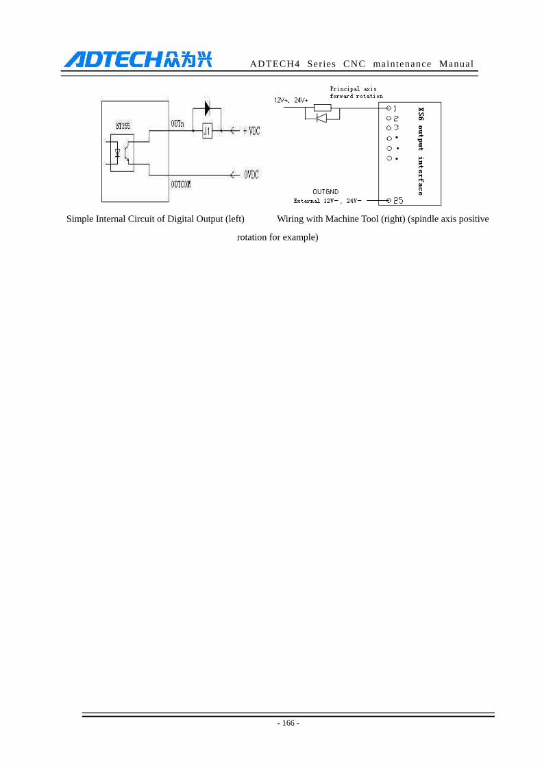
ADTECH4 Series CNC maintenance Manual
- 166 -
Simple Internal Circuit of Digital Output (left) Wiring with Machine Tool (right) (spindle axis positive
rotation for example)
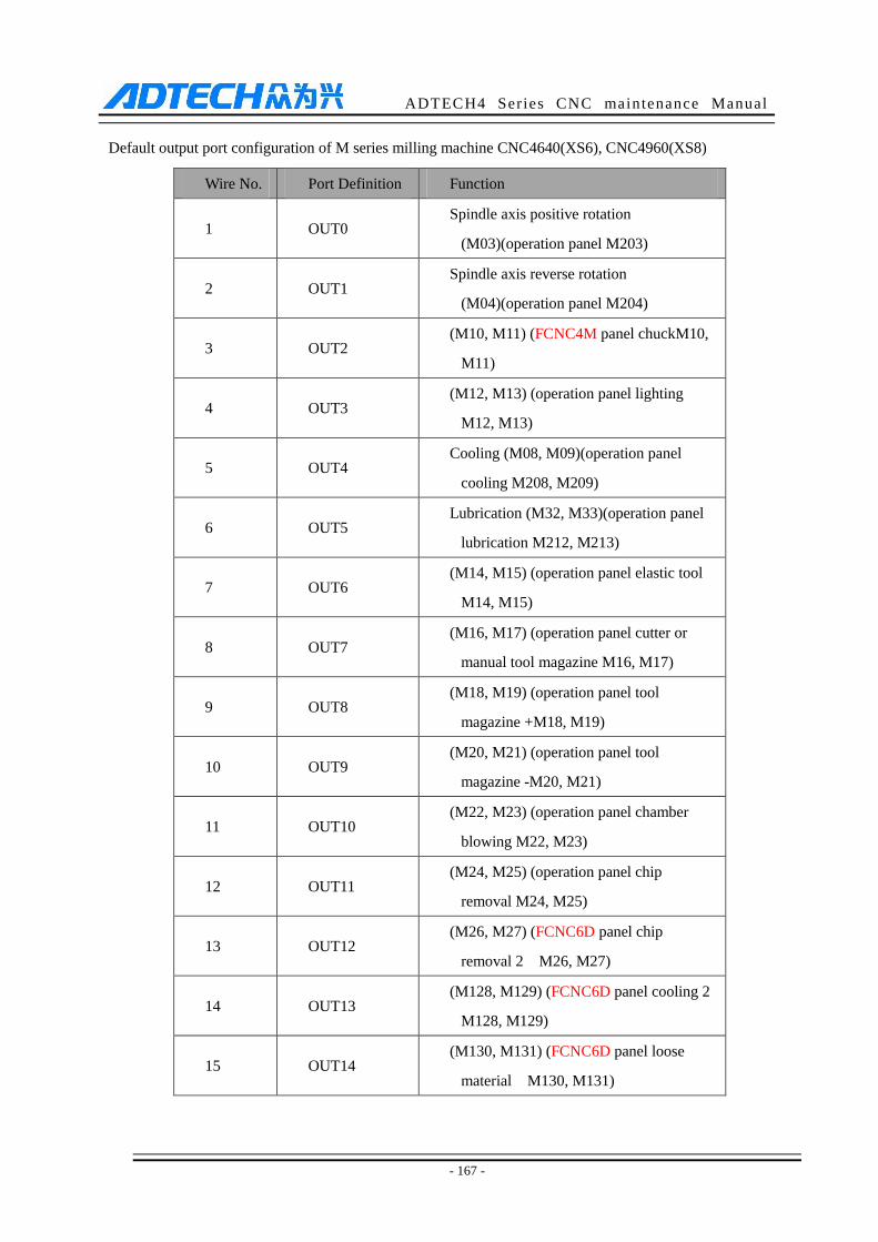
ADTECH4 Series CNC maintenance Manual
- 167 -
Default output port configuration of M series milling machine CNC4640(XS6), CNC4960(XS8)
Wire No. Port Definition Function
1 OUT0 Spindle axis positive rotation
(M03)(operation panel M203)
2 OUT1 Spindle axis reverse rotation
(M04)(operation panel M204)
3 OUT2 (M10, M11) (FCNC4M panel chuckM10,
M11)
4 OUT3 (M12, M13) (operation panel lighting
M12, M13)
5 OUT4 Cooling (M08, M09)(operation panel
cooling M208, M209)
6 OUT5 Lubrication (M32, M33)(operation panel
lubrication M212, M213)
7 OUT6 (M14, M15) (operation panel elastic tool
M14, M15)
8 OUT7 (M16, M17) (operation panel cutter or
manual tool magazine M16, M17)
9 OUT8 (M18, M19) (operation panel tool
magazine +M18, M19)
10 OUT9 (M20, M21) (operation panel tool
magazine -M20, M21)
11 OUT10 (M22, M23) (operation panel chamber
blowing M22, M23)
12 OUT11 (M24, M25) (operation panel chip
removal M24, M25)
13 OUT12 (M26, M27) (FCNC6D panel chip
removal 2 M26, M27)
14 OUT13 (M128, M129) (FCNC6D panel cooling 2
M128, M129)
15 OUT14 (M130, M131) (FCNC6D panel loose
material M130, M131)
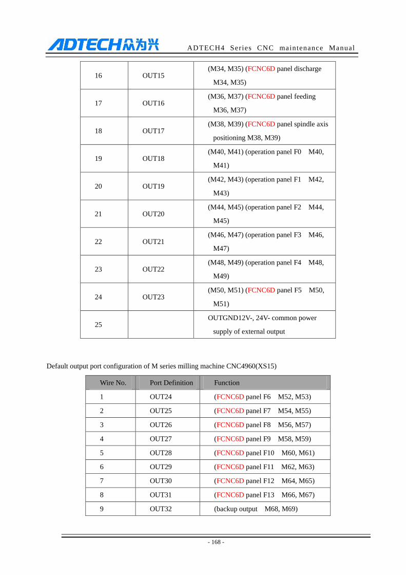
ADTECH4 Series CNC maintenance Manual
- 168 -
16 OUT15 (M34, M35) (FCNC6D panel discharge
M34, M35)
17 OUT16 (M36, M37) (FCNC6D panel feeding
M36, M37)
18 OUT17 (M38, M39) (FCNC6D panel spindle axis
positioning M38, M39)
19 OUT18 (M40, M41) (operation panel F0 M40,
M41)
20 OUT19 (M42, M43) (operation panel F1 M42,
M43)
21 OUT20 (M44, M45) (operation panel F2 M44,
M45)
22 OUT21 (M46, M47) (operation panel F3 M46,
M47)
23 OUT22 (M48, M49) (operation panel F4 M48,
M49)
24 OUT23 (M50, M51) (FCNC6D panel F5 M50,
M51)
25 OUTGND12V-, 24V- common power
supply of external output
Default output port configuration of M series milling machine CNC4960(XS15)
Wire No. Port Definition Function
1 OUT24 (FCNC6D panel F6 M52, M53)
2 OUT25 (FCNC6D panel F7 M54, M55)
3 OUT26 (FCNC6D panel F8 M56, M57)
4 OUT27 (FCNC6D panel F9 M58, M59)
5 OUT28 (FCNC6D panel F10 M60, M61)
6 OUT29 (FCNC6D panel F11 M62, M63)
7 OUT30 (FCNC6D panel F12 M64, M65)
8 OUT31 (FCNC6D panel F13 M66, M67)
9 OUT32 (backup output M68, M69)
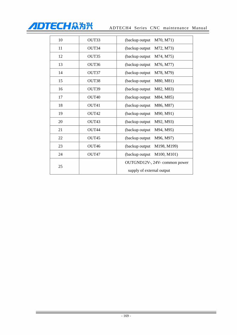
ADTECH4 Series CNC maintenance Manual
- 169 -
10 OUT33 (backup output M70, M71)
11 OUT34 (backup output M72, M73)
12 OUT35 (backup output M74, M75)
13 OUT36 (backup output M76, M77)
14 OUT37 (backup output M78, M79)
15 OUT38 (backup output M80, M81)
16 OUT39 (backup output M82, M83)
17 OUT40 (backup output M84, M85)
18 OUT41 (backup output M86, M87)
19 OUT42 (backup output M90, M91)
20 OUT43 (backup output M92, M93)
21 OUT44 (backup output M94, M95)
22 OUT45 (backup output M96, M97)
23 OUT46 (backup output M198, M199)
24 OUT47 (backup output M100, M101)
25 OUTGND12V-, 24V- common power
supply of external output
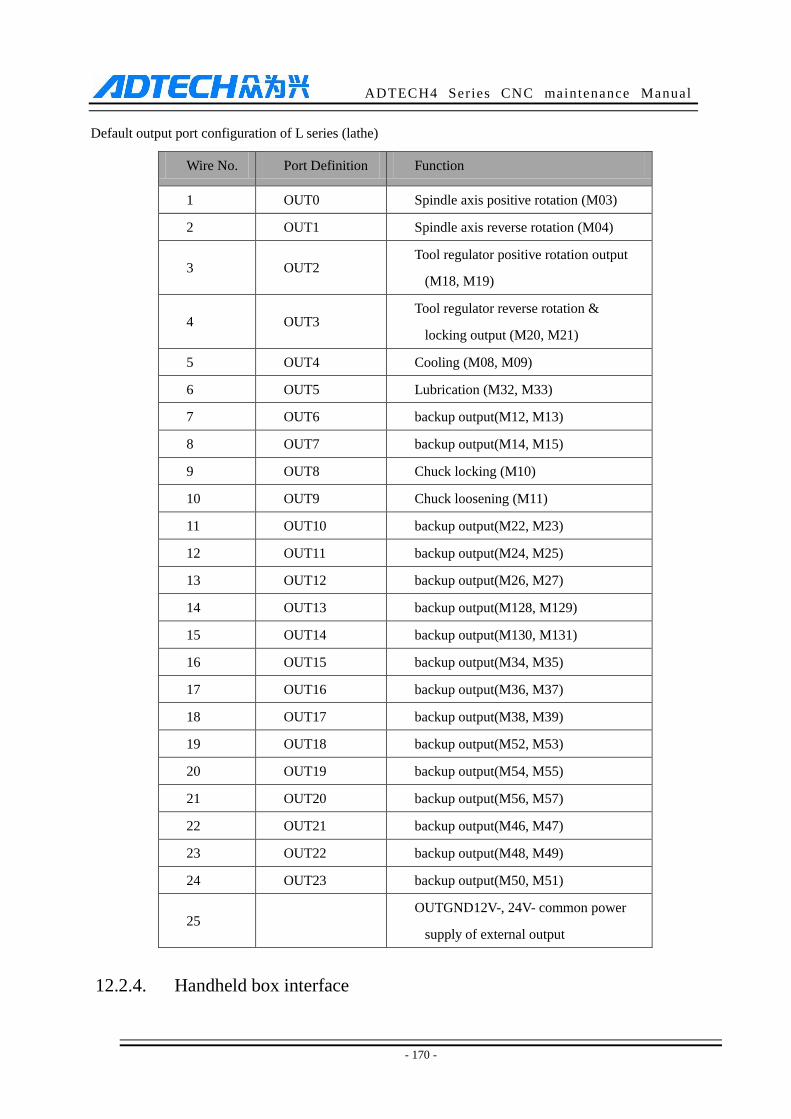
ADTECH4 Series CNC maintenance Manual
- 170 -
Default output port configuration of L series (lathe)
Wire No. Port Definition Function
1 OUT0 Spindle axis positive rotation (M03)
2 OUT1 Spindle axis reverse rotation (M04)
3 OUT2 Tool regulator positive rotation output
(M18, M19)
4 OUT3 Tool regulator reverse rotation &
locking output (M20, M21)
5 OUT4 Cooling (M08, M09)
6 OUT5 Lubrication (M32, M33)
7 OUT6 backup output(M12, M13)
8 OUT7 backup output(M14, M15)
9 OUT8 Chuck locking (M10)
10 OUT9 Chuck loosening (M11)
11 OUT10 backup output(M22, M23)
12 OUT11 backup output(M24, M25)
13 OUT12 backup output(M26, M27)
14 OUT13 backup output(M128, M129)
15 OUT14 backup output(M130, M131)
16 OUT15 backup output(M34, M35)
17 OUT16 backup output(M36, M37)
18 OUT17 backup output(M38, M39)
19 OUT18 backup output(M52, M53)
20 OUT19 backup output(M54, M55)
21 OUT20 backup output(M56, M57)
22 OUT21 backup output(M46, M47)
23 OUT22 backup output(M48, M49)
24 OUT23 backup output(M50, M51)
25 OUTGND12V-, 24V- common power
supply of external output
12.2.4. Handheld box interface
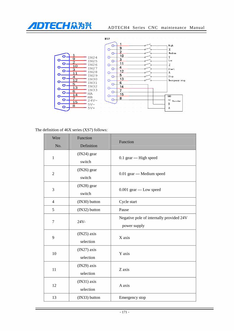
ADTECH4 Series CNC maintenance Manual
- 171 -
The definition of 46X series (XS7) follows:
Wire
No.
Function
Definition Function
1 (IN24) gear
switch 0.1 gear --- High speed
2 (IN26) gear
switch 0.01 gear --- Medium speed
3 (IN28) gear
switch 0.001 gear --- Low speed
4 (IN30) button Cycle start
5 (IN32) button Pause
7 24V- Negative pole of internally provided 24V
power supply
9 (IN25) axis
selection X axis
10 (IN27) axis
selection Y axis
11 (IN29) axis
selection Z axis
12 (IN31) axis
selection A axis
13 (IN33) button Emergency stop
HA
IN33
815714613512411310291
5V+
IN32
IN31
HB24V-
IN28
IN26
IN25
IN24
IN29
IN30
IN27
5V-

ADTECH4 Series CNC maintenance Manual
- 172 -
6 HA Hand encoder phase A input signal
14 HB Hand encoder phase B input signal
15 5V- Negative pole of internally provided 5V
power supply
8 +5V Positive pole of internally provided 5V
power supply
7 24V- Negative pole of internally provided 24V
power supply
49 series (XS9)
CNC4960 definition follows:
Wire No. Definition Function
1 IN63 0.1 gear switch – high
2 IN64 0.01 gear switch – medium
3 IN65 0.001 gear switch – low
4 IN60 Select C axis
5 IN61 Emergency stop
6 HA Hand encoder phase A input signal
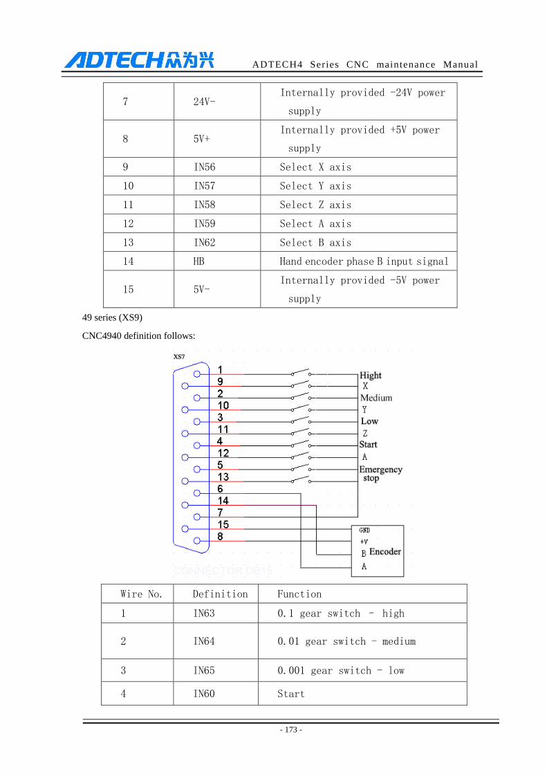
ADTECH4 Series CNC maintenance Manual
- 173 -
7 24V- Internally provided -24V power
supply
8 5V+ Internally provided +5V power
supply
9 IN56 Select X axis
10 IN57 Select Y axis
11 IN58 Select Z axis
12 IN59 Select A axis
13 IN62 Select B axis
14 HB Hand encoder phase B input signal
15 5V- Internally provided -5V power
supply
49 series (XS9)
CNC4940 definition follows:
Wire No. Definition Function
1 IN63 0.1 gear switch – high
2 IN64 0.01 gear switch - medium
3 IN65 0.001 gear switch - low
4 IN60 Start
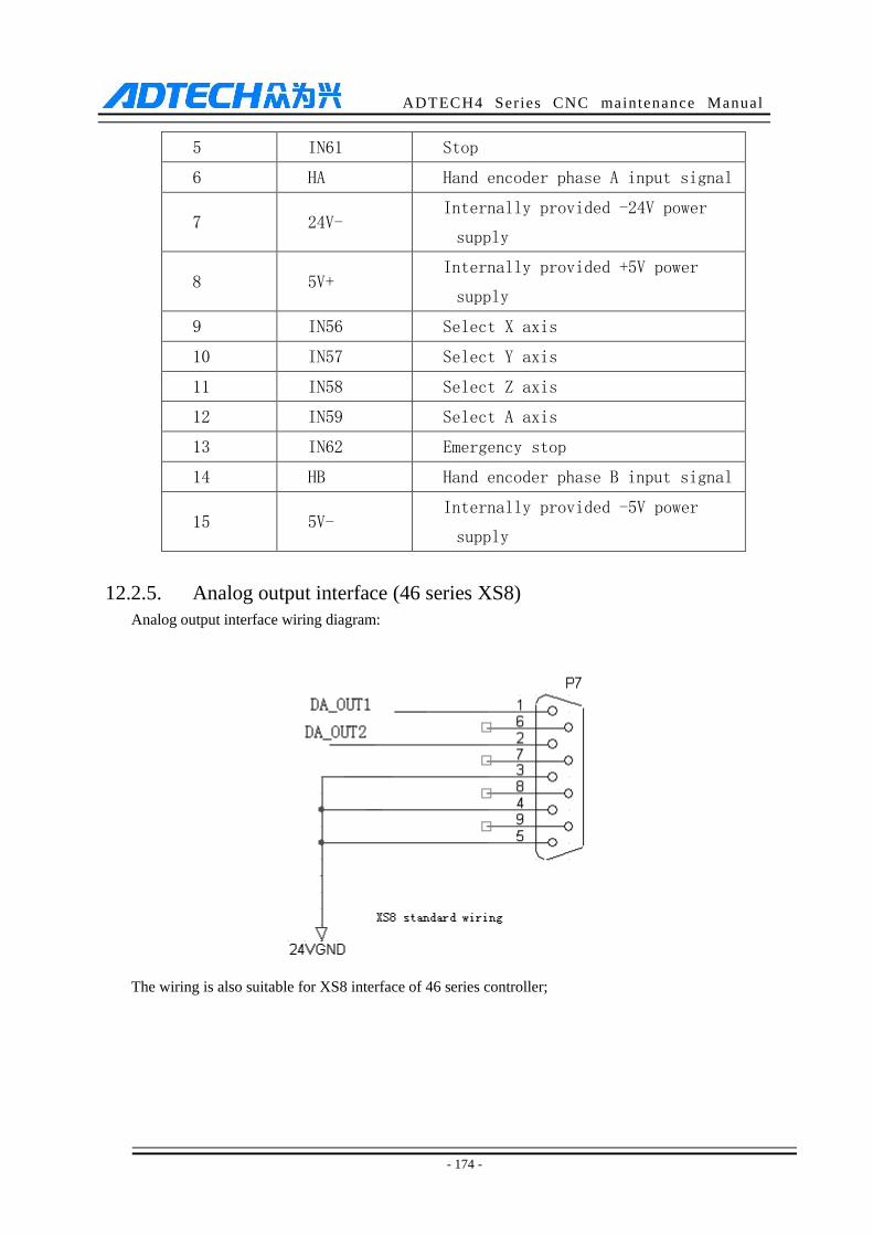
ADTECH4 Series CNC maintenance Manual
- 174 -
5 IN61 Stop
6 HA Hand encoder phase A input signal
7 24V- Internally provided -24V power
supply
8 5V+ Internally provided +5V power
supply
9 IN56 Select X axis
10 IN57 Select Y axis
11 IN58 Select Z axis
12 IN59 Select A axis
13 IN62 Emergency stop
14 HB Hand encoder phase B input signal
15 5V- Internally provided -5V power
supply
12.2.5. Analog output interface (46 series XS8)
Analog output interface wiring diagram:
The wiring is also suitable for XS8 interface of 46 series controller;
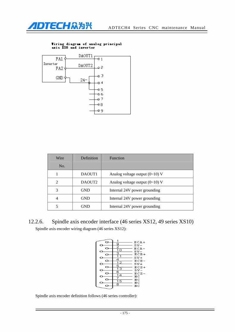
ADTECH4 Series CNC maintenance Manual
- 175 -
Wire
No.
Definition Function
1 DAOUT1 Analog voltage output (0~10) V
2 DAOUT2 Analog voltage output (0~10) V
3 GND Internal 24V power grounding
4 GND Internal 24V power grounding
5 GND Internal 24V power grounding
12.2.6. Spindle axis encoder interface (46 series XS12, 49 series XS10)
Spindle axis encoder wiring diagram (46 series XS12):
Spindle axis encoder definition follows (46 series controller):
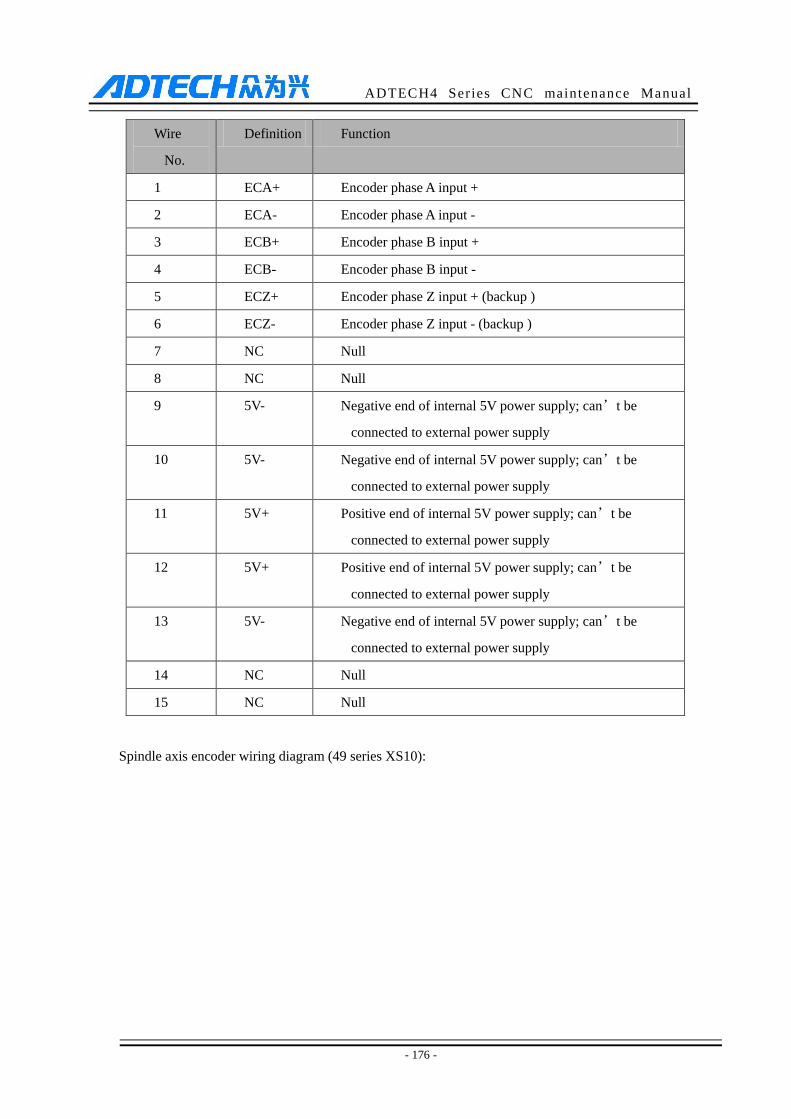
ADTECH4 Series CNC maintenance Manual
- 176 -
Wire
No.
Definition Function
1 ECA+ Encoder phase A input +
2 ECA- Encoder phase A input -
3 ECB+ Encoder phase B input +
4 ECB- Encoder phase B input -
5 ECZ+ Encoder phase Z input + (backup )
6 ECZ- Encoder phase Z input - (backup )
7 NC Null
8 NC Null
9 5V- Negative end of internal 5V power supply; can’t be
connected to external power supply
10 5V- Negative end of internal 5V power supply; can’t be
connected to external power supply
11 5V+ Positive end of internal 5V power supply; can’t be
connected to external power supply
12 5V+ Positive end of internal 5V power supply; can’t be
connected to external power supply
13 5V- Negative end of internal 5V power supply; can’t be
connected to external power supply
14 NC Null
15 NC Null
Spindle axis encoder wiring diagram (49 series XS10):
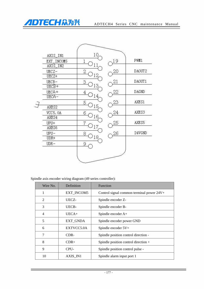
ADTECH4 Series CNC maintenance Manual
- 177 -
Spindle axis encoder wiring diagram (49 series controller):
Wire No. Definition Function
1 EXT_INCOM5 Control signal common terminal power 24V+
2 UECZ- Spindle encoder Z-
3 UECB- Spindle encoder B-
4 UECA+ Spindle encoder A+
5 EXT_GNDA Spindle encoder power GND
6 EXTVCC5.0A Spindle encoder 5V+
7 CDR- Spindle position control direction -
8 CDR+ Spindle position control direction +
9 CPU- Spindle position control pulse -
10 AXIS_IN1 Spindle alarm input port 1
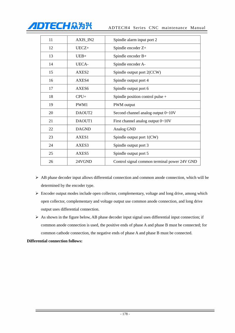
ADTECH4 Series CNC maintenance Manual
- 178 -
11 AXIS_IN2 Spindle alarm input port 2
12 UECZ+ Spindle encoder Z+
13 UEB+ Spindle encoder B+
14 UECA- Spindle encoder A-
15 AXES2 Spindle output port 2(CCW)
16 AXES4 Spindle output port 4
17 AXES6 Spindle output port 6
18 CPU+ Spindle position control pulse +
19 PWM1 PWM output
20 DAOUT2 Second channel analog output 0~10V
21 DAOUT1 First channel analog output 0~10V
22 DAGND Analog GND
23 AXES1 Spindle output port 1(CW)
24 AXES3 Spindle output port 3
25 AXES5 Spindle output port 5
26 24VGND Control signal common terminal power 24V GND
AB phase decoder input allows differential connection and common anode connection, which will be
determined by the encoder type.
Encoder output modes include open collector, complementary, voltage and long drive, among which
open collector, complementary and voltage output use common anode connection, and long drive
output uses differential connection.
As shown in the figure below, AB phase decoder input signal uses differential input connection; if
common anode connection is used, the positive ends of phase A and phase B must be connected; for
common cathode connection, the negative ends of phase A and phase B must be connected.
Differential connection follows:
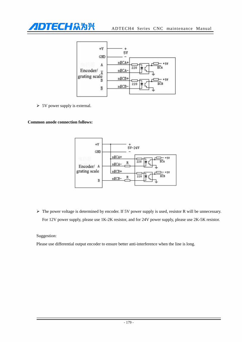
ADTECH4 Series CNC maintenance Manual
- 179 -
5V power supply is external.
Common anode connection follows:
The power voltage is determined by encoder. If 5V power supply is used, resistor R will be unnecessary.
For 12V power supply, please use 1K-2K resistor, and for 24V power supply, please use 2K-5K resistor.
Suggestion:
Please use differential output encoder to ensure better anti-interference when the line is long.

ADTECH4 Series CNC maintenance Manual
- 180 -
12.2.7. RS232 transmission interface (46 series XS9, 49 series XS11)
Serial communication interface ---9-core signal socket (male)
12.2.8. USB memory connection interface (46 series XS10)
Standard USB memory (e.g. USB disk) interface;
12.2.9. PC USB communication interface (46 series XS11, 49 series X13)
Standard USB communication interface;
12.3 Electrical connection diagram
12.3.1. Symbol schematic diagram
TXD
RXD
NC
NC
NC
NC
NC
GND594837261
NC
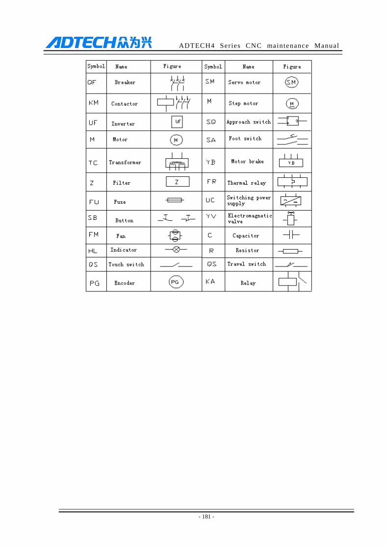
ADTECH4 Series CNC maintenance Manual
- 181 -
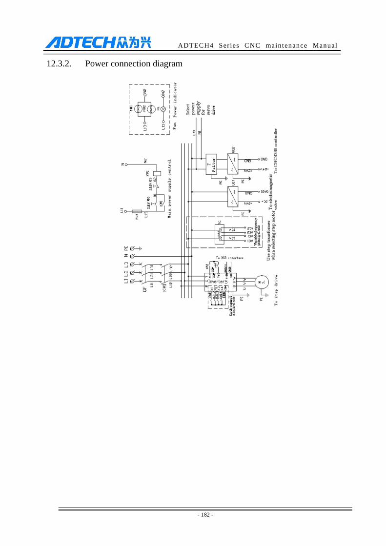
ADTECH4 Series CNC maintenance Manual
- 182 -
12.3.2. Power connection diagram
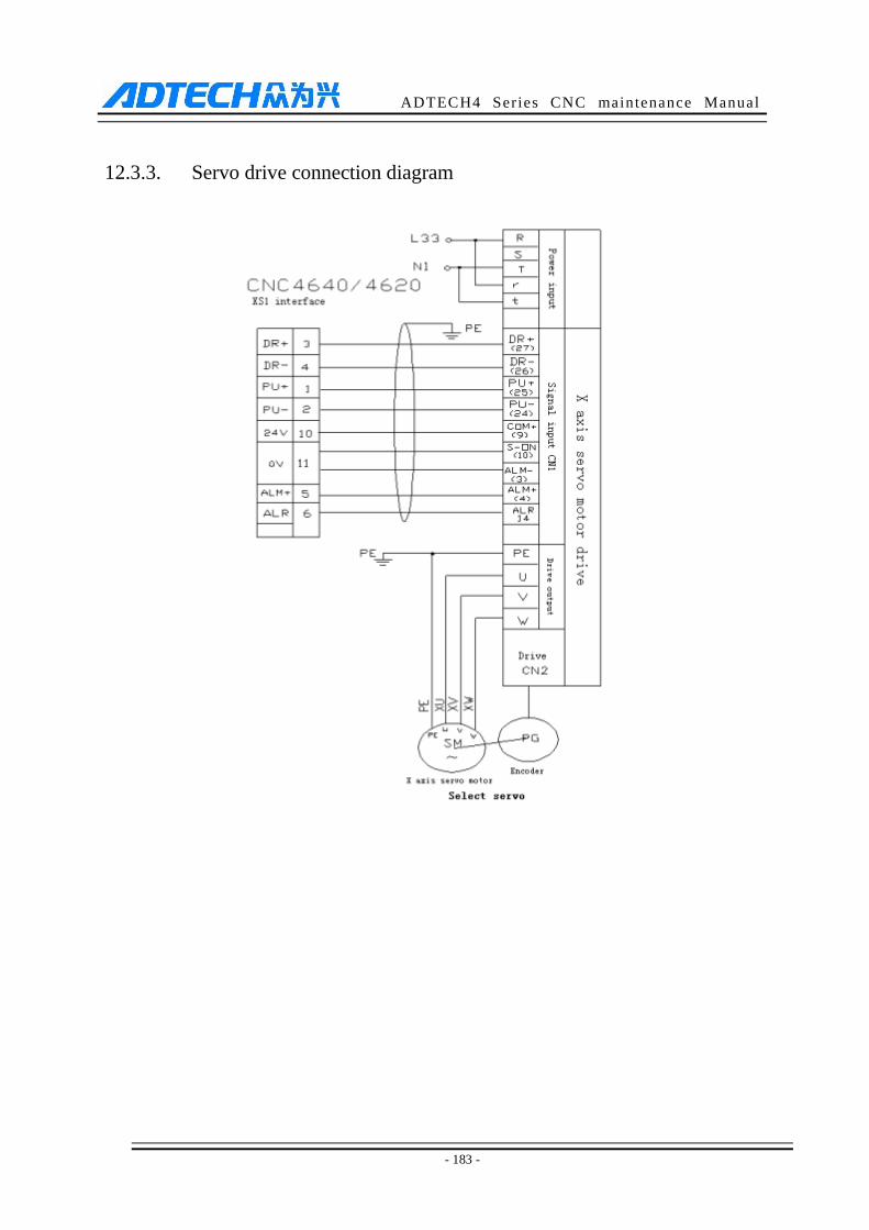
ADTECH4 Series CNC maintenance Manual
- 183 -
12.3.3. Servo drive connection diagram
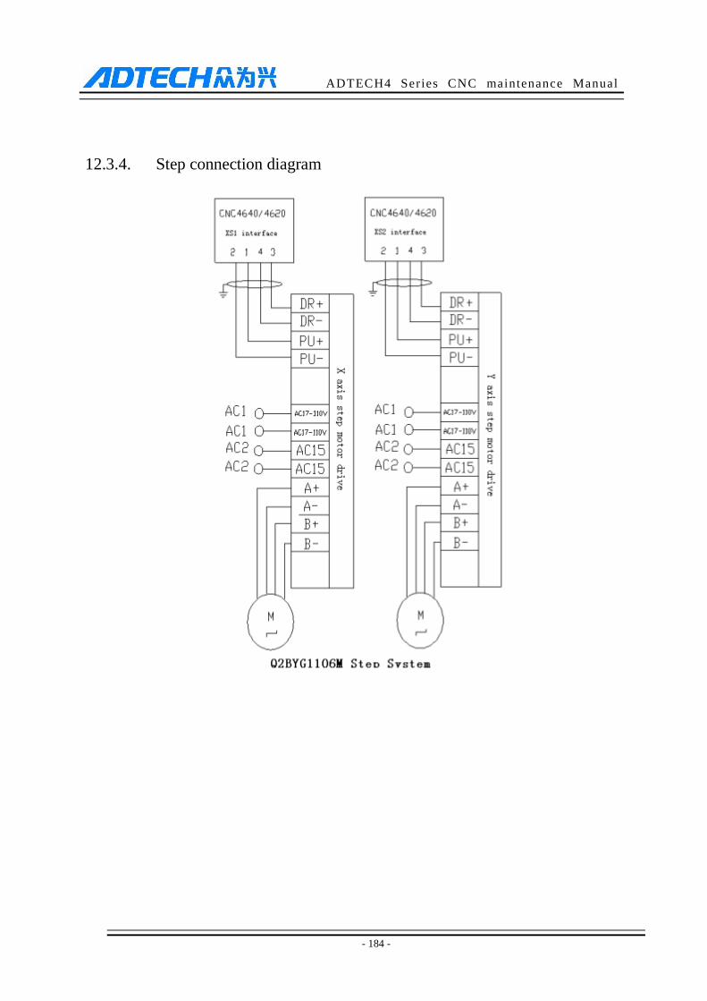
ADTECH4 Series CNC maintenance Manual
- 184 -
12.3.4. Step connection diagram
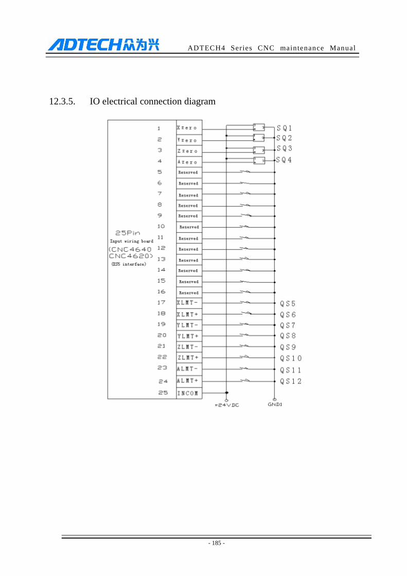
ADTECH4 Series CNC maintenance Manual
- 185 -
12.3.5. IO electrical connection diagram
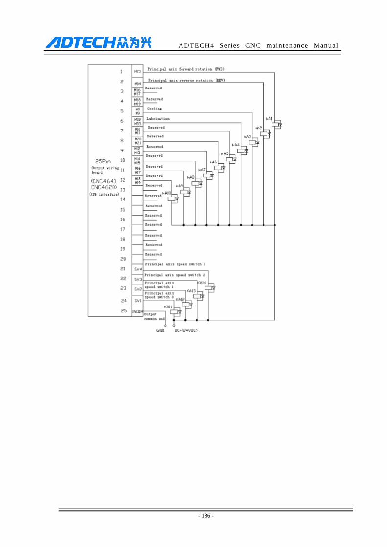
ADTECH4 Series CNC maintenance Manual
- 186 -
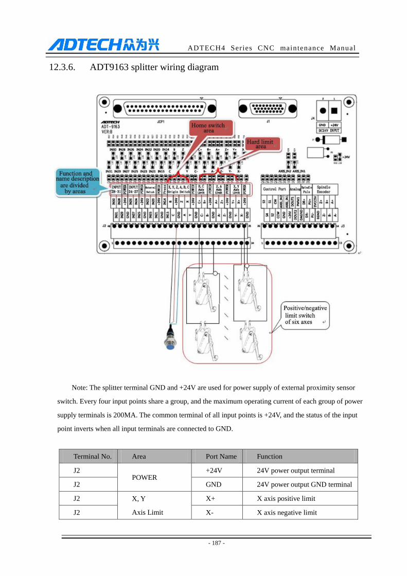
ADTECH4 Series CNC maintenance Manual
- 187 -
12.3.6. ADT9163 splitter wiring diagram
Note: The splitter terminal GND and +24V are used for power supply of external proximity sensor
switch. Every four input points share a group, and the maximum operating current of each group of power
supply terminals is 200MA. The common terminal of all input points is +24V, and the status of the input
point inverts when all input terminals are connected to GND.
Terminal No. Area Port Name Function
J2 POWER
+24V 24V power output terminal
J2 GND 24V power output GND terminal
J2 X, Y
Axis Limit
X+ X axis positive limit
J2 X- X axis negative limit
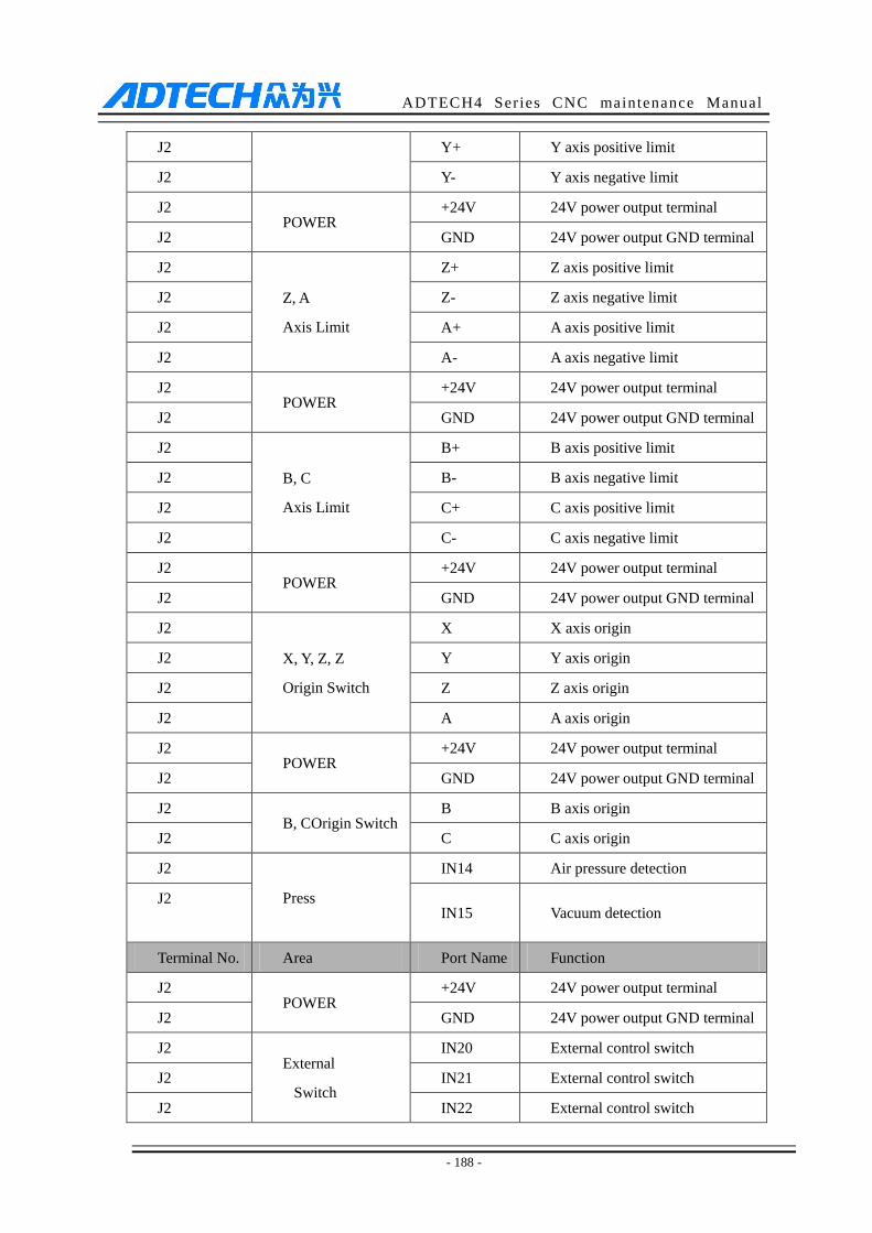
ADTECH4 Series CNC maintenance Manual
- 188 -
J2 Y+ Y axis positive limit
J2 Y- Y axis negative limit
J2 POWER
+24V 24V power output terminal
J2 GND 24V power output GND terminal
J2
Z, A
Axis Limit
Z+ Z axis positive limit
J2 Z- Z axis negative limit
J2 A+ A axis positive limit
J2 A- A axis negative limit
J2 POWER
+24V 24V power output terminal
J2 GND 24V power output GND terminal
J2
B, C
Axis Limit
B+ B axis positive limit
J2 B- B axis negative limit
J2 C+ C axis positive limit
J2 C- C axis negative limit
J2 POWER
+24V 24V power output terminal
J2 GND 24V power output GND terminal
J2
X, Y, Z, Z
Origin Switch
X X axis origin
J2 Y Y axis origin
J2 Z Z axis origin
J2 A A axis origin
J2 POWER
+24V 24V power output terminal
J2 GND 24V power output GND terminal
J2 B, COrigin Switch
B B axis origin
J2 C C axis origin
J2
Press
IN14 Air pressure detection
J2
IN15 Vacuum detection
Terminal No. Area Port Name Function
J2 POWER
+24V 24V power output terminal
J2 GND 24V power output GND terminal
J2 External
Switch
IN20 External control switch
J2 IN21 External control switch
J2 IN22 External control switch
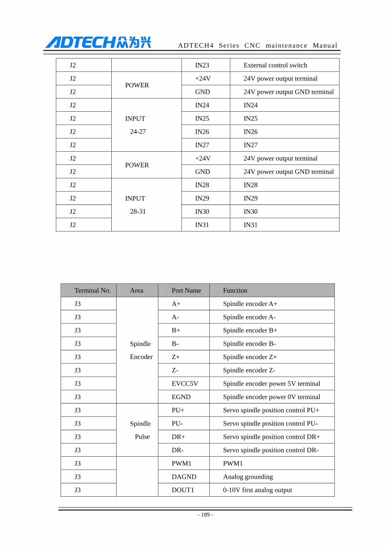
ADTECH4 Series CNC maintenance Manual
- 189 -
J2 IN23 External control switch
J2 POWER
+24V 24V power output terminal
J2 GND 24V power output GND terminal
J2
INPUT
24-27
IN24 IN24
J2 IN25 IN25
J2 IN26 IN26
J2 IN27 IN27
J2 POWER
+24V 24V power output terminal
J2 GND 24V power output GND terminal
J2
INPUT
28-31
IN28 IN28
J2 IN29 IN29
J2 IN30 IN30
J2 IN31 IN31
Terminal No. Area Port Name Function
J3
Spindle
Encoder
A+ Spindle encoder A+
J3 A- Spindle encoder A-
J3 B+ Spindle encoder B+
J3 B- Spindle encoder B-
J3 Z+ Spindle encoder Z+
J3 Z- Spindle encoder Z-
J3 EVCC5V Spindle encoder power 5V terminal
J3 EGND Spindle encoder power 0V terminal
J3
Spindle
Pulse
PU+ Servo spindle position control PU+
J3 PU- Servo spindle position control PU-
J3 DR+ Servo spindle position control DR+
J3 DR- Servo spindle position control DR-
J3
PWM1 PWM1
J3 DAGND Analog grounding
J3 DOUT1 0-10V first analog output
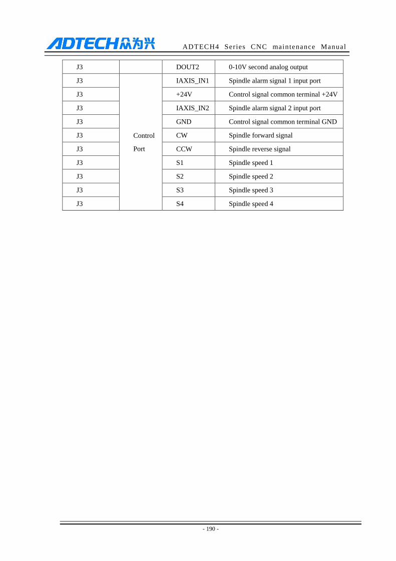
ADTECH4 Series CNC maintenance Manual
- 190 -
J3 DOUT2 0-10V second analog output
J3
Control
Port
IAXIS_IN1 Spindle alarm signal 1 input port
J3 +24V Control signal common terminal +24V
J3 IAXIS_IN2 Spindle alarm signal 2 input port
J3 GND Control signal common terminal GND
J3 CW Spindle forward signal
J3 CCW Spindle reverse signal
J3 S1 Spindle speed 1
J3 S2 Spindle speed 2
J3 S3 Spindle speed 3
J3 S4 Spindle speed 4
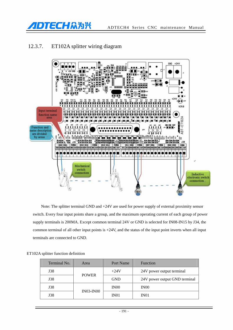
ADTECH4 Series CNC maintenance Manual
- 191 -
12.3.7. ET102A splitter wiring diagram
Note: The splitter terminal GND and +24V are used for power supply of external proximity sensor
switch. Every four input points share a group, and the maximum operating current of each group of power
supply terminals is 200MA. Except common terminal 24V or GND is selected for IN08-IN15 by J34, the
common terminal of all other input points is +24V, and the status of the input point inverts when all input
terminals are connected to GND.
ET102A splitter function definition
Terminal No. Area Port Name Function
J38 POWER
+24V 24V power output terminal
J38 GND 24V power output GND terminal
J38 IN03-IN00
IN00 IN00
J38 IN01 IN01
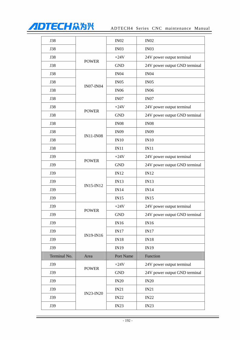
ADTECH4 Series CNC maintenance Manual
- 192 -
J38 IN02 IN02
J38 IN03 IN03
J38 POWER
+24V 24V power output terminal
J38 GND 24V power output GND terminal
J38
IN07-IN04
IN04 IN04
J38 IN05 IN05
J38 IN06 IN06
J38 IN07 IN07
J38 POWER
+24V 24V power output terminal
J38 GND 24V power output GND terminal
J38
IN11-IN08
IN08 IN08
J38 IN09 IN09
J38 IN10 IN10
J38 IN11 IN11
J39 POWER
+24V 24V power output terminal
J39 GND 24V power output GND terminal
J39
IN15-IN12
IN12 IN12
J39 IN13 IN13
J39 IN14 IN14
J39 IN15 IN15
J39 POWER
+24V 24V power output terminal
J39 GND 24V power output GND terminal
J39
IN19-IN16
IN16 IN16
J39 IN17 IN17
J39 IN18 IN18
J39 IN19 IN19
Terminal No. Area Port Name Function
J39 POWER
+24V 24V power output terminal
J39 GND 24V power output GND terminal
J39
IN23-IN20
IN20 IN20
J39 IN21 IN21
J39 IN22 IN22
J39 IN23 IN23
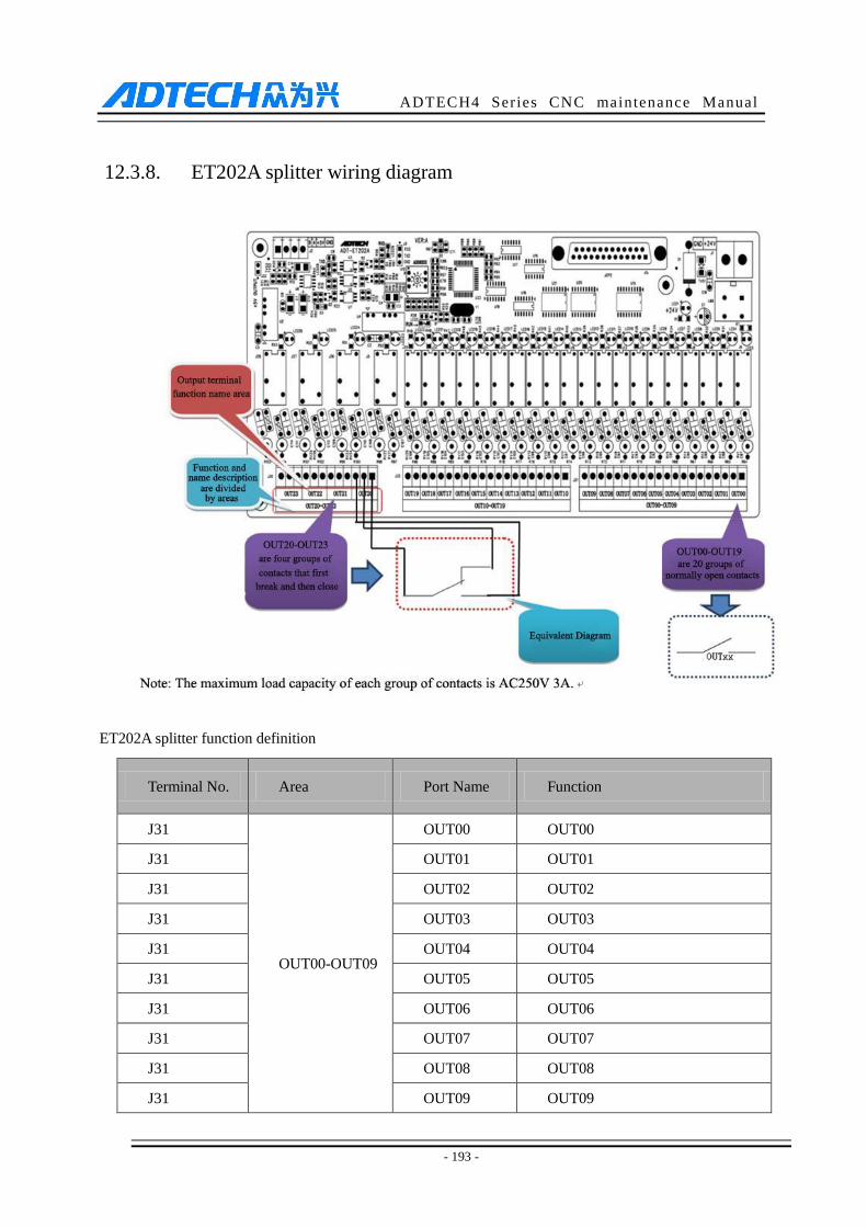
ADTECH4 Series CNC maintenance Manual
- 193 -
12.3.8. ET202A splitter wiring diagram
ET202A splitter function definition
Terminal No. Area Port Name Function
J31
OUT00-OUT09
OUT00 OUT00
J31 OUT01 OUT01
J31 OUT02 OUT02
J31 OUT03 OUT03
J31 OUT04 OUT04
J31 OUT05 OUT05
J31 OUT06 OUT06
J31 OUT07 OUT07
J31 OUT08 OUT08
J31 OUT09 OUT09

ADTECH4 Series CNC maintenance Manual
- 194 -
J32
OUT10-OUT19
OUT10 OUT10
J32 OUT11 OUT11
J32 OUT12 OUT12
J32 OUT13 OUT13
J32 OUT14 OUT14
J32 OUT15 OUT15
J32 OUT16 OUT16
J32 OUT17 OUT17
J32 OUT18 OUT18
J32 OUT19 OUT19
J30
OUT20-OUT23
OUT20 OUT20
J30 OUT21 OUT21
J30 OUT22 OUT22
J30 OUT23 OUT23