Adopting Model-Based Design for FPGA, ASIC, and SoC ... · FPGA, ASIC, and SoC Development Projects...
38
1 © 2015 The MathWorks, Inc. Adopting Model-Based Design for FPGA, ASIC, and SoC Development Jonas Rutström
Transcript of Adopting Model-Based Design for FPGA, ASIC, and SoC ... · FPGA, ASIC, and SoC Development Projects...

1© 2015 The MathWorks, Inc.
Adopting Model-Based Design for
FPGA, ASIC, and SoC
Development
Jonas Rutström

2
Agenda
▪ Why Model-Based Design for FPGA, ASIC, or SoC?
▪ Case Study – Pulse Detector
▪ HW/SW Co-Design
▪ How to get started?
Just an example, the workflow is the
same for...

3
Agenda
▪ Why Model-Based Design for FPGA, ASIC, or SoC?
▪ Case Study – Pulse Detector
▪ HW/SW Co-Design
▪ How to get started?

4
Some statistics…

5
FPGA, ASIC, and SoC Development Projects
67% of ASIC/FPGA projects are behind schedule
75% of ASIC projects require a silicon re-spin
Over 50% of project time is spent on verification
Statistics from 2018 Mentor Graphics / Wilson
Research survey, averaged over FPGA/ASIC
84% of FPGA projects have non-trivial
bugs escape into production

6
Why is it like this?

7
SPECIFICATIONS
SPECIFICATIONS
Many Different Skill Sets Need to Collaborate
Algorithms
System Architecture
System Integration
REQUIREMENTSRESEARCHRESEARCH
SPECIFICATIONS
Verification
Analog
Hardware
Embedded
Software
Digital
Hardware
“At a late stage in the project, we received
a new requirement for the controller to
provide feedback on its own status. That
kind of change would take at least a week
to make with hand coding.”
Rob Reilink
DEMCON
• Poor communication across teams
• Key decisions made in silos
• System-level issues found in late stages
• Hard to adapt to changing requirements
• Different specification languages

8
DESIGN
SoC Collaboration with Model-Based Design
Algorithms
System Architecture
System Integration
REQUIREMENTSRESEARCHRESEARCH
Analog
Hardware
Embedded
SoftwareDigital
Hardware
Implementation Architectures
Implementation Knowledge
Generate Code
Export Models
Verific
atio
nV
alid
atio
n &
HOW am I
making it?
Is it going to
work?
Have I made
it right?
Am I making
the right
thing?Design Elaboration
SIMULATION
WHAT am I
making?
MAKE IT!

9
Agenda
▪ Why Model-Based Design for FPGA, ASIC, or SoC?
▪ Case Study – Pulse Detector
▪ HW/SW Co-Design
▪ How to get started?

10
Case Study Overview | Pulse Detector
1. Example Overview
2. Reference Pulse Detector
3. Pulse Detector Design
4. Prepare for Hardware Implementation
5. Fixed-point Conversion
6. HDL code generation and verification

11
Pulse Detector | Overview
Send Receive Detect

12
Hardware Implementation
(HDL)
Detector Design
(Simulink)
Pulse Detector | Overview
Reference Design
(MATLAB)

13
Case Study Overview | Pulse Detector
1. Example Overview
2. Reference Pulse Detector
3. Pulse Detector Design
4. Prepare for Hardware Implementation
5. Fixed-point Conversion
6. HDL code generation and verification

14
Pulse Detector | Reference Design (MATLAB)
- Matched Filter
- Filtering
- Find Peak
Core Components
DEMO

15
Case Study Overview | Pulse Detector
1. Example Overview
2. Reference Pulse Detector
3. Pulse Detector Design
4. Prepare for Hardware Implementation
5. Fixed-point Conversion
6. HDL code generation and verification

16
Pulse Detector | Design in SimulinkStreaming Architecture
In this step, we will:
▪ Create a Simulink model with streaming input
▪ Implement a hardware-friendly peak finder
▪ Compare the Simulink pulse detector to the MATLAB golden reference
DEMO

17
Case Study Overview | Pulse Detector
1. Example Overview
2. Reference Pulse Detector
3. Pulse Detector Design
4. Prepare for Hardware Implementation
5. Fixed-point Conversion
6. HDL code generation and verification
18
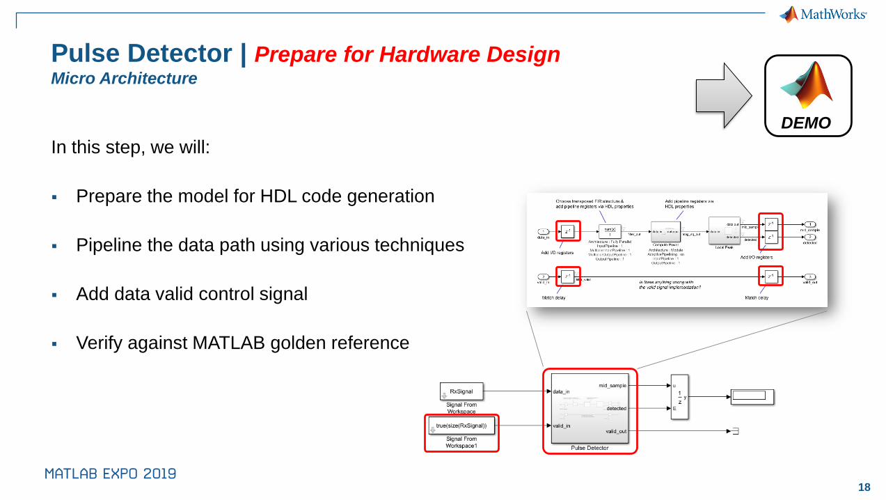
Pulse Detector | Prepare for Hardware DesignMicro Architecture
In this step, we will:
▪ Prepare the model for HDL code generation
▪ Pipeline the data path using various techniques
▪ Add data valid control signal
▪ Verify against MATLAB golden reference
DEMO

19
Case Study Overview | Pulse Detector
1. Example Overview
2. Reference Pulse Detector
3. Pulse Detector Design
4. Prepare for Hardware Implementation
5. Fixed-point Conversion
6. HDL code generation and verification

20
Pulse Detector | Fixed-Point Conversion
In this step, we will:
▪ Convert the model to fixed-point
– Add a Data Type Conversion blocks
– Define data types: DT_input, DT_coeff, DT_filter, DT_power
▪ Compare the Simulink fixed-point model to the MATLAB golden reference
DEMO

21
Some words about Fixed-Point conversion...

22
Fixed-Point Conversion | Automated Approach

23
Fixed-Point Conversion | Native Floating-Point
Fixed-Point
Mix Fixed- and
Floating-Point
Saturate on overflow
High dynamic range
HDL Coder Native Floating Point
• Extensive math and trigonometric
operator support
• Optimal implementations without
sacrificing numerical accuracy
• Mix floating- and fixed-point operations
• Generate target-independent HDL

24
Case Study Overview | Pulse Detector
1. Example Overview
2. Reference Pulse Detector
3. Pulse Detector Design
4. Prepare for Hardware Implementation
5. Fixed-point Conversion
6. HDL code generation and verification

25
Pulse Detector | HDL Code Generation and Verification
In this step, we will:
▪ Check the model for HDL compatibility
▪ Generate HDL code and reports
▪ Verify the design
– Co-simulation with QuestaSim
DEMO

26
Case Study Overview | Pulse Detector
1. Example Overview
2. Reference Pulse Detector
3. Pulse Detector Design
4. Prepare for Hardware Implementation
5. Fixed-point Conversion
6. HDL code generation and verification

27
A few more words about verification...

28
Verification | Generate SystemVerilog DPI Components for RTL
▪ Reuse MATLAB/Simulink models in verification
– Individual components or entire test bench
▪ Generate from frame-based or streaming algorithm
▪ Floating-point or fixed-point
– Runs natively in SystemVerilog simulator
– Eliminate re-work and miscommunication
– Save testbench development time
– Easy to update when requirements change

29
Agenda
▪ Why Model-Based Design for FPGA, ASIC, or SoC?
▪ Case Study – Pulse Detector
▪ HW/SW Co-Design
▪ How to get started?

30
HW/SW Design

31
How to simulate the architecture together
with the algorithms?

32
SoC Blockset | Model and Simulate SoC Architecture

33
SoC Blockset | Model and Simulate SoC Architecture

34
SoC Blockset | Example
Latency Requirements

35
Agenda
▪ Why Model-Based Design for FPGA, ASIC, or SoC?
▪ Case Study – Pulse Detector
▪ HW/SW Co-Design
▪ How to get started?

36
Learn More | Resources
▪ Next steps to get started with:
– Incremental refinement, HDL code generation: HDL self-guided tutorial
– Fixed-point quantization: Fixed-Point Made Easy webinar
– Verification: Improve RTL Verification by Connecting to MATLAB webinar
– SoC Blockset: Getting Started with SoC Blockset

37
Learn More | User Stories
Industry Customers Typically use our products for:
Airbus
BAE Systems
Reutech Radar
Wireless/satellite comms
Flight control
Radar
Allegro Micro
Huawei
Nokia
NXP Automotive
Renesas
Wireless comms
Verification
Sensors
ADAS
Power electronics
Bosch
Punch Powertrain
Hella
Valeo
ADAS
Motor control
Sensor design
Sensor design
3T Systems
J-PARC
Motor control
Power converter control
Abbott Labs
DEMCON
Olympus
Implantable sensors
Motor/power control
Diagnostic imaging
AeroDef
CES
Auto
IA&M
Med Dev

38
Questions?