Adopted and Approved Petition for Rule Making · Testing Method Adapted From Method C of ......
18
1 Adopted and Approved Petition for Rule Making Re: Additional code language for Section 403.2.2 of the NC Energy Conservation Code. Proposed Alternative Duct Testing Method Adapted From Method C of ASTM E1554 – Using Fan Pressurization of Distribution System and Building at a Fixed Reference Pressure for Combined Supply and Return Leaks. From: NC Energy Efficiency Alliance and Appalachian State University Department of Technology and Environmental Design Date: 8/29/12 The current NC Energy Conservation Code requires duct testing to be verified and identifies one method of doing so. The proposed language below would allow for a leakage to the outside test to be performed as an alternative testing method. The exact proposed language is below in bold black print. This involves REVISING section 403.2.2 to read as seen below. In revising that language it creates the need to ADD new language that would allow leakage to the outside as another testing option. Therefore, sub-sections of 403.2.2 have been created (seen below as 403.2.2.1 and 403.2.2.2) to identify 1) total leakage testing and 2) leakage to the outside testing. 403.2.2 Sealing (Mandatory Requirements). All ducts, air handlers, filter boxes and building cavities used as ducts shall be sealed. Joints and seams shall comply with Part V – Mechanical, Section 603.9 of the North Carolina Residential Code. Duct testing shall be verified by compliance with Section 403.2.2.1 or 403.2.2.2. Duct testing shall be verified as follows: 403.2.2.1 Total Duct leakage. Total duct leakage less than or equal to 6 CFM (12 L/min) per 100 ft 2 (9.29 m 2 ) of conditioned floor area served by that system when tested at a pressure differential of 0.1 inches w.g. (25 Pa) across the entire system, including the manufacturer’s air handler enclosure. During testing: 1. Block, if present, ventilation air duct(s) connected to the conditioning system. 2. The duct air leakage testing equipment shall be attached to the largest return in the system or to the air handler. 3. The filter shall be removed and the air handler power shall be turned off. 4. Supply boots or registers and return boxes or grilles shall be taped, plugged, or otherwise sealed air tight. 5. The hose for measuring the 25 Pascals of pressure differential shall be inserted into the boot of the supply that is nominally closest to the air handler.
Transcript of Adopted and Approved Petition for Rule Making · Testing Method Adapted From Method C of ......

1
Adopted and Approved Petition for Rule Making
Re: Additional code language for Section 403.2.2 of the NC Energy Conservation Code. Proposed Alternative Duct Testing Method Adapted From Method C of ASTM E1554 – Using Fan Pressurization of Distribution System and Building at a Fixed Reference Pressure for Combined Supply and Return Leaks.
From: NC Energy Efficiency Alliance and Appalachian State University Department of Technology and Environmental Design
Date: 8/29/12
The current NC Energy Conservation Code requires duct testing to be verified and identifies one method of doing so. The proposed language below would allow for a leakage to the outside test to be performed as an alternative testing method.
The exact proposed language is below in bold black print. This involves REVISING section 403.2.2 to read as seen below. In revising that language it creates the need to ADD new language that would allow leakage to the outside as another testing option. Therefore, sub-sections of 403.2.2 have been created (seen below as 403.2.2.1 and 403.2.2.2) to identify 1) total leakage testing and 2) leakage to the outside testing.
403.2.2 Sealing (Mandatory Requirements). All ducts, air handlers, filter boxes and building cavities used as ducts shall be sealed. Joints and seams shall comply with Part V – Mechanical, Section 603.9 of the North Carolina Residential Code. Duct testing shall be verified by compliance with Section 403.2.2.1 or 403.2.2.2.
Duct testing shall be verified as follows:
403.2.2.1 Total Duct leakage. Total duct leakage less than or equal to 6 CFM (12 L/min) per 100 ft2 (9.29 m2) of conditioned floor area served by that system when tested at a pressure differential of 0.1 inches w.g. (25 Pa) across the entire system, including the manufacturer’s air handler enclosure.
During testing:
1. Block, if present, ventilation air duct(s) connected to the conditioning system.
2. The duct air leakage testing equipment shall be attached to the largest return in the system or to the air handler.
3. The filter shall be removed and the air handler power shall be turned off.
4. Supply boots or registers and return boxes or grilles shall be taped, plugged, or otherwise sealed air tight.
5. The hose for measuring the 25 Pascals of pressure differential shall be inserted into the boot of the supply that is nominally closest to the air handler.

2
6. Specific instructions from the duct testing equipment manufacturer shall be followed to reach duct test pressure and measure duct air leakage.
403.2.2.2 Duct Leakage to the Outside. Conduct the test using fan pressurization of distribution system and building at a fixed reference pressure for combined supply and return leak. Duct leakage to the outside shall be less than or equal to 6 CFM (12 L/min) per 100 ft2 (9.29 m2) of conditioned floor area served by that system when tested at a pressure differential of 0.1 inches w.g. (25 Pa) across the entire system, relative to the outside, including the manufacturer’s air handler enclosure.
During testing:
1. Block, if present, the ventilation air duct(s) connected to the conditioning system. 2. The duct air leakage testing equipment shall be attached to the largest return in the system or to the
air handler. 3. The filter shall be removed and the air handler power shall be turned off. 4. Supply boots or registers and return boxes or grilles shall be taped, plugged, or otherwise sealed air
tight or as tight as possible. 5. The hose for measuring the 25 Pascals of pressure differential shall be inserted into the boot of the
supply that is nominally closest to the air handler. 6. Open all interconnecting doors in the building, close dampers for fireplaces and other operable
dampers. 7. Set up an envelope air moving/ flow-regulating/ flow measurement assembly, such as a blower door,
following the manufacturer’s prescribed procedure. 8. Specific instructions from the duct testing equipment manufacturer shall be followed to reach duct test
pressure and measure duct air leakage used in combination with a blower door. Typical steps are as follows:
a. Depressurize the ductwork system to 25 Pa using the measurement hose in Step 5 above. b. Depressurize the house to 25 Pa using an envelope air moving/ flow-regulating/ flow
measurement assembly, such as a blower door. c. Correct the duct pressure to measure 0 Pa of pressure differential between the house and the
ductwork system. d. Read the CFM of duct leakage using the procedures for the specific equipment being used.
(Note that most automatically calculating pressure gauges cannot compute the CFM25 automatically with a duct-to-house difference in pressure of 0 Pa, so the gauge setting should be set to read CFM instead of CFM25).
Duct Testing shall be performed and reported by the permit holder, a NC licensed general contractor, a NC licensed HVAC contractor, a NC licensed Home Inspector, a registered design professional, a certified BPI Envelope Professional or a certified HERS rater. A single point depressurization, not temperature corrected, test is sufficient to comply with this provision, provided that the duct testing fan assembly(s) has been certified by the manufacturer to be capable of conducting tests in accordance with ASTM E1554-07.
The duct leakage information, including duct leakage result, tester name, date, and contact information, shall be included on the certificate described in Section 401.3.
For the Test Criteria, the report shall be produced in the following manner: perform the HVAC system air leakage test and record the CFM25. Calculate the total square feet of Conditioned Floor Area (CFA) served by that system. Multiply CFM25 by 100, divide the result by the CFA and record the result. If the result is less than

3
or equal to 6 CFM25/100 SF the HVAC system air tightness is acceptable. Appendix 3C contains optional sample worksheets for duct testing for the permit holder’s use only.
Exceptions to testing requirements:
1. Duct systems or portions thereof inside the building thermal envelope shall not be required to be leak tested.
2. Installation of a partial system as part of replacement, renovation or addition does not require a duct leakage test.
Reason: (part of the petition) Multiple reasons exist for adding an alternate duct testing method. They are:
1. The proposed testing procedure measures duct leakage to outside therefore it isolates those duct leaks that are OUTSIDE of the building envelope. This idea is in-line with the intent of the new 2012 Energy Conservation Code and provides flexibility to those authorized to perform and report the results.
2. This test is done in unison with a blower door fan assembly and therefore allows authorized testers to demonstrate both building envelope tightness (when the testing option is used) and duct tightness in one single test.
3. In situations where it is difficult to seal supply and return runs in the home the leakage to outside test is favorable. While these supply and return runs are still required to be sealed any small air leaks present will be leaks “in the home” not “to the outside” and therefore will not grossly affect the test results.
4. The North Carolina Energy Efficiency Alliance (NCEEA) and the NC Department of Insurance have fielded many questions and requests from Home Energy Raters across the state who seek to use this method to satisfy code compliant work they are performing for the builder.
Economic Impact: (part of the petition) This proposed test will be an optional, alternative offering therefore it has no significant economic impact. Fiscal Analysis: (part of the petition) This testing provision is an optional, alternative method therefore will be no added construction cost associated with this proposal.

4
APPENDIX 3C Duct sealing. Duct air leakage test (Section 403.2.2)
Sample Worksheet
403.2.2 Sealing (Mandatory Requirements). All ducts, air handlers, filter boxes and building cavities used as ducts shall be sealed. Joints and seams shall comply with Part V – Mechanical, Section 603 of the NC Mechanical Code.
Duct testing shall be verified as follows: using one of the two following methods:
1)Total Duct leakage. Total duct leakage less than or equal to 6 CFM (12 L/min) per 100 ft2 (9.29 m2) of conditioned floor area served by that system when tested at a pressure differential of 0.1 inches w.g. (25 Pa) across the entire system, including the manufacturer’s air handler enclosure.
During testing: 1. Block, if present, ventilation air duct(s) connected to the conditioning system. 2. The duct air leakage testing equipment shall be attached to the largest return in the system or to the air handler. 3. The filter shall be removed and the air handler power shall be turned off. 4. Supply boots or registers and return boxes or grilles shall be taped, plugged, or otherwise sealed air tight. 5. The hose for measuring the 25 Pascals of pressure differential shall be inserted into the boot of the supply that is nominally closest to the air handler. 6. Specific instructions from the duct testing equipment manufacturer shall be followed to reach duct test pressure and measure duct air leakage.
2) Duct Leakage to the Outside. Conduct the test using fan pressurization of distribution system and building at a fixed reference pressure for combined supply and return leaks. Duct leakage to the outside shall be less than or equal to 6 CFM (12 L/min) per 100 ft2 (9.29 m2) of conditioned floor area served by that system when tested at a pressure differential of 0.1 inches w.g. (25 Pa) across the entire system, relative to the outside, including the manufacturer’s air handler enclosure.
During testing:
1. Block, if present, the ventilation air duct(s) connected to the conditioning system. 2. The duct air leakage testing equipment shall be attached to the largest return in the system or to the air
handler. 3. The filter shall be removed and the air handler power shall be turned off. 4. Supply boots or registers and return boxes or grilles shall be taped, plugged, or otherwise sealed air tight
or as tight as possible. 5. The hose for measuring the 25 Pascals of pressure differential shall be inserted into the boot of the
supply that is nominally closest to the air handler. 6. Open all interconnecting doors in the building, close dampers for fireplaces and other operable dampers. 7. Set up an envelope air moving/ flow-regulating/ flow measurement assembly, such as a blower door,
following the manufacturer’s prescribed procedure. 8. Specific instructions from the duct testing equipment manufacturer shall be followed to reach duct test
pressure and measure duct air leakage used in combination with a blower door. Typical steps are as follows:
a. Depressurize the ductwork system to 25 Pa using the measurement hose in Step 5 above. b. Depressurize the house to 25 Pa using an envelope air moving/ flow-regulating/ flow
measurement assembly, such as a blower door.

5
c. Correct the duct pressure to measure 0 Pa of pressure differential between the house and the ductwork system.
d. Read the CFM of duct leakage using the procedures for the specific equipment being used. (Note that most automatically calculating pressure gauges cannot compute the CFM25 automatically with a duct-to-house difference in pressure of 0 Pa, so the gauge setting should be set to read CFM instead of CFM25).
Testing shall be performed and reported by the permit holder, a NC licensed general contractor, a NC licensed HVAC contractor, a NC licensed Home Inspector, a registered design professional, a certified BPI Envelope Professional or a certified HERS rater. A single point depressurization, not temperature corrected, test is sufficient to comply with this provision, provided that the duct testing fan assembly(s) has been certified by the manufacturer to be capable of conducting tests in accordance with ASTM E1554-07.
The duct leakage information, including duct leakage result, tester name, date, and contact information, shall be included on the certificate described in Section 401.3.
For the Test Criteria, the report shall be produced in the following manner: perform the HVAC system air leakage test and record the CFM25. Calculate the total square feet of Conditioned Floor Area (CFA) served by that system. Multiply CFM25 by 100, divide the result by the CFA and record the result. If the result is less than or equal to [6 CFM25/100 SF] the HVAC system air tightness is acceptable.
Complete one duct leakage report for each HVAC system serving the home: Property Address: ________________________________________________________________
HVAC System Number: _________ Describe area of home served: _____________________
CFM25 Total _________. Conditioned Floor Area (CFA) served by system: __________ s.f.
CFM25 x 100 divided by CFA = ____ CFM25/100SF (e.g. 100 CFM25x100/ 2,000 CFA = 5 CFM25/100SF)
Fan attachment location ___________________
Company Name __________________________________________________________________
Contact Information:_______________________________________________________________
_______________________________________________________________________________
_______________________________________ ______________________________
Signature of Tester Date
Permit Holder, NC Licensed General Contractor, NC Licensed HVAC Contractor, NC Licensed Home Inspector,
Registered Design Professional,
Certified BPI Envelope Professional, or Certified HERS Rater (circle one)

6
APPENDIX 4 ADDITIONAL VOLUNTARY CRITERIA FOR INCREASING ENERGY EFFICIENCY (High Efficiency Residential Option)
1. Introduction. The increased energy efficiency measures identified in this appendix are strictly voluntary at the option of the permit holder and have been evaluated to be the most cost effective measures for achieving an additional 15-20% energy efficiency beyond the code minimums.
2. Requirements: Follow all sections of the Chapter 4 of the North Carolina Energy Conservation Code, except the
following.
a. Instead of using Table 402.1.1 in Section 402.1.1, use Table E-4A shown below.
TABLE 4A
INSULATION AND FENESTRATION REQUIREMENTS BY COMPONENTa
CLIMATE ZONE
FENESTRATION U-FACTORb
SKYLIGHTb U-FACTOR
GLAZED FENESTRATION
SHGCb, e
CEILING R-VALUEk
WOOD FRAME WALL
R-VALUE e
MASS WALL
R-VALUEi
FLOOR R-VALUE
BASEMENTc WALL
R-VALUE
SLABd R-VALUE
CRAWL SPACEc
WALL R-VALUE
3 0.32j 0.65 0.25 38 19, 13+5,
or 15+3eh
5/10 19 10/13f 5 10/13
4 0.32 0.60 0.25 38 19, 13+5,
or 15+3eh
5/10 19 10/13 10 10/13
5 0.32 0.60 (NR) 38 19, 13+5,
or 15+3eh
13/17 30g 10/13 10 15/19
For SI: 1 foot = 304.8 mm. a. R-values are minimums. U-factors and SHGC are maximums.
b. The fenestration U-factor column excludes skylights. The SHGC column applies to all glazed fenestration.
c. “10/13” means R-10 continuous insulated sheathing on the interior or exterior of the home or R-13 cavity insulation at the interior of the basement wall or crawl space wall.
d. For monolithic slabs, insulation shall be applied from the inspection gap downward to the bottom of the footing or a maximum of 18 inches below grade,
whichever is less . For floating slabs, insulation shall extend to the bottom of the foundation wall or 24 inches, whichever is less. (See Appendix O) R-5 shall be added to the required slab edge R-values for heated slabs.
e. R -19 fiberglass batts compressed and installed in a nominal 2 × 6 framing cavity is deemed to comply. Fiberglass batts rated R-19 or higher compressed and
installed in a 2x4 wall is not deemed to comply. f. Basement wall insulation is not required in warm-humid locations as defined by Figure 301.2 and Tables 301.1 and 301.3.
g. Or insulation sufficient to fill the framing cavity, R-19 minimum.
h. “13+5” means R-13 cavity insulation plus R-5 insulated sheathing. 15+3 means R-15 cavity insulation plus R-3 insulated sheathing. If structural sheathing covers 25 percent or less of the exterior, insulating sheathing is not required where structural sheathing is used. If structural sheathing covers more than 25
percent of exterior, structural sheathing shall be supplemented with insulated sheathing of at least R-2. 13+2.5 means R-13 cavity insulation plus R-2.5
sheathing. i. For Mass Walls, the second R-value applies when more than half the insulation is on the interior of the mass wall.
j. R-30 shall be deemed to satisfy the ceiling insulation requirement wherever the full height of uncompressed R-30 insulation extends over the wall top plate at
the eaves. Otherwise R-38 insulation is required where adequate clearance exists or insulation must extend to either the insulation baffle or within 1” of the attic roof deck.
k. Table value required except for roof edge where the space is limited by the pitch of the roof, there the insulation must fill the space up to the air baffle.
b. Instead of using Table 402.1.3 in Section 402.1.3, use Table E-4B to find the maximum U-factors for
building components. 3. TABLE 4B
4. EQUIVALENT U-FACTORSa
CLIMATE ZONE
FENESTRATION U-FACTOR
SKYLIGHT U-FACTOR
CEILING U-FACTOR
FRAME WALL
U-FACTOR
MASS WALL
U-FACTORb
FLOOR U-FACTOR
BASEMENT WALL
U-FACTORd
CRAWL SPACE WALL
U-FACTORc
3 0.32 0.65 0.035 0.082 0.141 0.047 0.059 0.136
4 0.32 0.60 0.030 0.071 0.141 0.047 0.059 0.065
5 0.32 0.60 0.030 0.067 0.082 0.033 0.059 0.065 a. Nonfenestration U-factors shall be obtained from measurement, calculation or an approved source. b. When more than half the insulation is on the interior, the mass wall U-factors shall be a maximum 0.12 in Zone 3, 0.10 in Zone 4, and the same as the frame
wall U-factor in Zone 5.
c. Basement wall U-factor of 0.360 in warm-humid locations as defined by Figures 401.2(1), 401.2(2) and Table 401.2. d. Foundation U-factor requirements shown in Table E-5B include wall construction and interior air films but exclude soil conductivity and exterior air films.
U-factors for determining code compliance in accordance with Section 402.1.3 (total UA alternative) shall be modified to include soil conductivity and exterior
air films.

7
c. Instead of using the air leakage value for maximum leakage shown in Section 402.4.2.2, use the following:
i. 0.24 CFM50/Square Foot of Surface Area (SFSA) or
ii. Four (4) air changes per hour (ACH50)
d. Instead of using the duct leakage value for maximum leakage shown in Section 403.2.2 use the following:
Total duct leakage or leakage to the outside shall be less than or equal to 4 CFM (12 L/min) per 100 ft2
(9.29 m2) of conditioned floor area served by that system when tested at a pressure differential of 0.1
inches w.g. (25 Pa) across
Table 4C: Sample Confirmation Form for ADDITIONAL VOLUNTARY CRITERIA FOR INCREASING ENERGY EFFICIENCY (High Efficiency Residential Option) Proposed
Project
Values
Climate Zone 3
Fenestration U-Factor 0.32 j
Skylight U-Factor 0.65
Glazed Fenestration SHGC b, e 0.25
Ceiling R-value 38
Wood Frame Wall R-value e 19, 13+5,
or 15+3eh
Mass Wall R-value j 5/10
Floor R-value 19
Basement Wall R-value c
10/13 f
Slab R-value and Depth d 5, 2 ft
Crawl Space Wall R-value c 10/13
Building Air Leakage
Visually inspected according to
N1102.4.2.1 (check box) OR
Building Air Leakage Test
according to N1102.4.2.2 (check
box). Show test value:
ACH50 [Target: 4.0], or
CFM50/SFSA [Target: 0.24]
Name of Tester / Company:
Date:
Phone:
Duct Insulation and Sealing
Insulation Value
Duct Leakage Test Result
(Sect. N1103.2.2)
(CFM25 Total/100SF)
[Target:4]
Name of Tester or Company:
Date:
Phone:
North Carolina Energy Conservation Code: High
Efficiency Residential Option
Insulation and Fenestration Values
4 5
0.25 (NR)
38 38
0.32 j
0.32 j
0.6 0.6
19 30 g
10/13 f
10/13 f
19, 13+5, or 15+3eh
19, 13+5, or 15+3eh
5/10 13/17
10, 2 ft 10, 2 ft
10/13 15/19
R-

8
4D.3 Duct sealing. Duct air leakage test (Section 403.2.2)
Sample Worksheet for Alternative Residential Energy Code for Higher Efficiency
403.2.2 Sealing. All ducts, air handlers, filter boxes and building cavities used as ducts shall be sealed. Joints and seams shall comply with Part V – Mechanical, Section 603 of the NC Mechanical Code.
Duct testing shall be verified as follows: using one of the two following methods:
1)Total Duct leakage. Total duct leakage less than or equal to 4 CFM (12 L/min) per 100 ft2 (9.29 m2) of conditioned floor area served by that system when tested at a pressure differential of 0.1 inches w.g. (25 Pa) across the entire system, including the manufacturer’s air handler enclosure.
During testing: 1. Block, if present, ventilation air duct(s) connected to the conditioning system. 2. The duct air leakage testing equipment shall be attached to the largest return in the system or to the air handler. 3. The filter shall be removed and the air handler power shall be turned off. 4. Supply boots or registers and return boxes or grilles shall be taped, plugged, or otherwise sealed air tight. 5. The hose for measuring the 25 Pascals of pressure differential shall be inserted into the boot of the supply that is nominally closest to the air handler. 6. Specific instructions from the duct testing equipment manufacturer shall be followed to reach duct test pressure and measure duct air leakage.
2) Duct Leakage to the Outside. Conduct the test using fan pressurization of distribution system and building at a fixed reference pressure for combined supply and return leaks. Duct leakage to the outside shall be less than or equal to 4 CFM (12 L/min) per 100 ft2 (9.29 m2) of conditioned floor area served by that system when tested at a pressure differential of 0.1 inches w.g. (25 Pa) across the entire system, relative to the outside, including the manufacturer’s air handler enclosure.
During testing:
1. Block, if present, the ventilation air duct(s) connected to the conditioning system. 2. The duct air leakage testing equipment shall be attached to the largest return in the system or to the air
handler. 3. The filter shall be removed and the air handler power shall be turned off. 4. Supply boots or registers and return boxes or grilles shall be taped, plugged, or otherwise sealed air tight
or as tight as possible. 5. The hose for measuring the 25 Pascals of pressure differential shall be inserted into the boot of the
supply that is nominally closest to the air handler. 6. Open all interconnecting doors in the building, close dampers for fireplaces and other operable dampers. 7. Set up an envelope air moving/ flow-regulating/ flow measurement assembly, such as a blower door,
following the manufacturer’s prescribed procedure. 8. Specific instructions from the duct testing equipment manufacturer shall be followed to reach duct test
pressure and measure duct air leakage used in combination with a blower door. Typical steps are as follows:
a. Depressurize the ductwork system to 25 Pa using the measurement hose in Step 5 above. b. Depressurize the house to 25 Pa using an envelope air moving/ flow-regulating/ flow
measurement assembly, such as a blower door.

9
c. Correct the duct pressure to measure 0 Pa of pressure differential between the house and the ductwork system.
d. Read the CFM of duct leakage using the procedures for the specific equipment being used. (Note that most automatically calculating pressure gauges cannot compute the CFM25 automatically with a duct-to-house difference in pressure of 0 Pa, so the gauge setting should be set to read CFM instead of CFM25).
Testing shall be performed and reported by the permit holder, a NC licensed general contractor, a NC licensed HVAC contractor, a NC licensed Home Inspector, a registered design professional, a certified BPI Envelope Professional or a certified HERS rater. A single point depressurization, not temperature corrected, test is sufficient to comply with this provision, provided that the duct testing fan assembly(s) has been certified by the manufacturer to be capable of conducting tests in accordance with ASTM E1554-07.
The duct leakage information, including duct leakage result, tester name, date, and contact information, shall be included on the certificate described in Section 401.3.
For the Test Criteria, the report shall be produced in the following manner: perform the HVAC system air leakage test and record the CFM25. Calculate the total square feet of Conditioned Floor Area (CFA) served by that system. Multiply CFM25 by 100, divide the result by the CFA and record the result. If the result is less than or equal to [4 CFM25/100 SF] the HVAC system air tightness is acceptable.
Complete one duct leakage report for each HVAC system serving the home: Property Address: ________________________________________________________________
HVAC System Number: _________ Describe area of home served: _____________________
CFM25 Total _________. Conditioned Floor Area (CFA) served by system: __________ s.f.
CFM25 x 100 divided by CFA = ____ CFM25/100SF (e.g. 70 CFM25x100/ 2,000 CFA = 3.5 CFM25/100SF)
Fan attachment location ___________________
Company Name __________________________________________________________________
Contact Information:_______________________________________________________________
_______________________________________________________________________________
_______________________________________ ______________________________
Signature of Tester Date
Permit Holder, NC Licensed General Contractor, NC Licensed HVAC Contractor, NC Licensed Home Inspector,
Registered Design Professional,
Certified BPI Envelope Professional, or Certified HERS Rater (circle one)

10
Adopted and Approved Petition for Rule Making
Re: Additional code language for Section 1103.2.2 of the NC Residential Code. Proposed Alternative Duct Testing Method Adapted From Method C of ASTM E1554 – Using Fan Pressurization of Distribution System and Building at a Fixed Reference Pressure for Combined Supply and Return Leaks.
From: NC Energy Efficiency Alliance and Appalachian State University Department of Technology and Environmental Design
Date: 8/29/12
The current NC Energy Conservation Code requires duct testing to be verified and identifies one method of doing so. The proposed language below would allow for a leakage to the outside test to be performed as an alternative testing method.
The exact proposed language is below in bold black print. This involves REVISING section 1103.2.2 to read as seen below. In revising that language it creates the need to ADD new language that would allow leakage to the outside as another testing option. Therefore, sub-sections of 1103.2.2 have been created (seen below as 1103.2.2.1 and 1103.2.2.2) to identify 1) total leakage testing and 2) leakage to the outside testing.
1103.2.2 Sealing (Mandatory Requirements). All ducts, air handlers, filter boxes and building cavities used as ducts shall be sealed. Joints and seams shall comply with Part V – Mechanical, Section 603.9 of the North Carolina Residential Code. Duct testing shall be verified by compliance with Section 1103.2.2.1 or 1103.2.2.2:
Duct tightness shall be verified as follows:
1103.2.2.1 Total Duct leakage. Total duct leakage less than or equal to 6 CFM (12 L/min) per 100 ft2 (9.29 m2) of conditioned floor area served by that system when tested at a pressure differential of 0.1 inches w.g. (25 Pa) across the entire system, including the manufacturer’s air handler enclosure.
During testing:
1. Block, if present, ventilation air duct(s) connected to the conditioning system.
2. The duct air leakage testing equipment shall be attached to the largest return in the system or to the air handler.
3. The filter shall be removed and the air handler power shall be turned off.
4. Supply boots or registers and return boxes or grilles shall be taped, plugged, or otherwise sealed air tight.
5. The hose for measuring the 25 Pascals of pressure differential shall be inserted into the boot of the supply that is nominally closest to the air handler.

11
6. Specific instructions from the duct testing equipment manufacturer shall be followed to reach duct test pressure and measure duct air leakage.
1103.2.2.2 Duct Leakage to the Outside. Conduct the test using fan pressurization of distribution system and building at a fixed reference pressure for combined supply and return leaks. Duct leakage to the outside shall be less than or equal to 6 CFM (12 L/min) per 100 ft2 (9.29 m2) of conditioned floor area served by that system when tested at a pressure differential of 0.1 inches w.g. (25 Pa) across the entire system, relative to the outside, including the manufacturer’s air handler enclosure.
During testing:
1. Block, if present, the ventilation air duct connected to the conditioning system. 2. The duct air leakage testing equipment shall be attached to the largest return in the system or to the
air handler. 3. The filter shall be removed and the air handler power shall be turned off. 4. Supply boots or registers and return boxes or grilles shall be taped, plugged, or otherwise sealed air
tight or as tight as possible. 5. The hose for measuring the 25 Pascals of pressure differential shall be inserted into the boot of the
supply that is nominally closest to the air handler. 6. Open all interconnecting doors in the building, close dampers for fireplaces and other operable
dampers. 7. Set up an envelope air moving/ flow-regulating/ flow measurement assembly, such as a blower door,
following the manufacturer’s prescribed procedure. 8. Specific instructions from the duct testing equipment manufacturer shall be followed to reach duct test
pressure and measure duct air leakage used in combination with a blower door. Typical steps are as follows:
a. Depressurize the ductwork system to 25 Pa using the measurement hose in Step 5 above. b. Depressurize the house to 25 Pa using an envelope air moving/ flow-regulating/ flow
measurement assembly, such as a blower door. c. Correct the duct pressure to measure 0 Pa of pressure differential between the house and the
ductwork system. d. Read the CFM of duct leakage using the procedures for the specific equipment being used.
(Note that most automatically calculating pressure gauges cannot compute the CFM25 automatically with a duct-to-house difference in pressure of 0 Pa, so the gauge setting should be set to read CFM instead of CFM25).
Duct Testing shall be performed and reported by the permit holder, a NC licensed general contractor, a NC licensed HVAC contractor, a NC licensed Home Inspector, a registered design professional, a certified BPI Envelope Professional or a certified HERS rater. A single point depressurization, not temperature corrected, test is sufficient to comply with this provision, provided that the duct testing fan assembly(s) has been certified by the manufacturer to be capable of conducting tests in accordance with ASTM E1554-07.
The duct leakage information, including duct leakage result, tester name, date, and contact information, shall be included on the certificate described in Section 401.3.
For the Test Criteria, the report shall be produced in the following manner: perform the HVAC system air leakage test and record the CFM25. Calculate the total square feet of Conditioned Floor Area (CFA) served by that system. Multiply CFM25 by 100, divide the result by the CFA and record the result. If the result is less than

12
or equal to 6 CFM25/100 SF the HVAC system air tightness is acceptable. Appendix 3C contains optional sample worksheets for duct testing for the permit holder’s use only.
Exceptions to testing requirements:
1. Duct systems or portions thereof inside the building thermal envelope shall not be required to be leak tested.
2. Installation of a partial system as part of replacement, renovation or addition does not require a duct leakage test.
Reason: (part of the petition) Multiple reasons exist for adding an alternate duct testing method. They are:
1. The proposed testing procedure measures duct leakage to outside therefore it isolates those duct leaks that are OUTSIDE of the building envelope. This idea is in-line with the intent of the new 2012 Energy Conservation Code and provides flexibility to those authorized to perform and report the results.
2. This test is done in unison with a blower door fan assembly and therefore allows authorized testers to demonstrate both building envelope tightness (when the testing option is used) and duct tightness in one single test.
3. In situations where it is difficult to seal supply and return runs in the home the leakage to outside test is favorable. While these supply and return runs are still required to be sealed any small air leaks present will be leaks “in the home” not “to the outside” and therefore will not grossly affect the test results.
4. The North Carolina Energy Efficiency Alliance (NCEEA) and the NC Department of Insurance have fielded many questions and requests from Home Energy Raters across the state who seek to use this method to satisfy code compliant work they are performing for the builder.
Economic Impact: (part of the petition) This proposed test will be an optional, alternative offering therefore it has no significant economic impact. Fiscal Analysis: (part of the petition) This testing provision is an optional, alternative method therefore will be no added construction cost associated with this proposal.

13
APPENDIX 3C Duct sealing. Duct air leakage test (Section 1103.2.2)
Sample Worksheet
1103.2.2 Sealing (Mandatory Requirements). All ducts, air handlers, filter boxes and building cavities used as ducts shall be sealed. Joints and seams shall comply with Part V – Mechanical, Section 603 of the NC Mechanical Code.
Duct testing shall be verified as follows: using one of the two following methods:
1)Total Duct leakage. Total duct leakage less than or equal to 6 CFM (12 L/min) per 100 ft2 (9.29 m2) of conditioned floor area served by that system when tested at a pressure differential of 0.1 inches w.g. (25 Pa) across the entire system, including the manufacturer’s air handler enclosure.
During testing: 1. Block, if present, ventilation air duct(s) connected to the conditioning system. 2. The duct air leakage testing equipment shall be attached to the largest return in the system or to the air handler. 3. The filter shall be removed and the air handler power shall be turned off. 4. Supply boots or registers and return boxes or grilles shall be taped, plugged, or otherwise sealed air tight. 5. The hose for measuring the 25 Pascals of pressure differential shall be inserted into the boot of the supply that is nominally closest to the air handler. 6. Specific instructions from the duct testing equipment manufacturer shall be followed to reach duct test pressure and measure duct air leakage.
2) Duct leakage to the Outside. Conduct the test using fan pressurization of distribution system and building at a fixed reference pressure for combined supply and return leaks. Duct leakage to the outside shall be less than or equal to 6 CFM (12 L/min) per 100 ft2 (9.29 m2) of conditioned floor area served by that system when tested at a pressure differential of 0.1 inches w.g. (25 Pa) across the entire system, relative to the outside, including the manufacturer’s air handler enclosure.
During testing:
1. Block, if present, the ventilation air duct(s) connected to the conditioning system. 2. The duct air leakage testing equipment shall be attached to the largest return in the system or to the air
handler. 3. The filter shall be removed and the air handler power shall be turned off. 4. Supply boots or registers and return boxes or grilles shall be taped, plugged, or otherwise sealed air tight
or as tight as possible. 5. The hose for measuring the 25 Pascals of pressure differential shall be inserted into the boot of the
supply that is nominally closest to the air handler. 6. Open all interconnecting doors in the building, close dampers for fireplaces and other operable dampers. 7. Set up an envelope air moving/ flow-regulating/ flow measurement assembly, such as a blower door,
following the manufacturer’s prescribed procedure. 8. Specific instructions from the duct testing equipment manufacturer shall be followed to reach duct test
pressure and measure duct air leakage used in combination with a blower door. Typical steps are as follows:
a. Depressurize the ductwork system to 25 Pa using the measurement hose in Step 5 above. b. Depressurize the house to 25 Pa using an envelope air moving/ flow-regulating/ flow
measurement assembly, such as a blower door.

14
c. Correct the duct pressure to measure 0 Pa of pressure differential between the house and the ductwork system.
d. Read the CFM of duct leakage using the procedures for the specific equipment being used. (Note that most automatically calculating pressure gauges cannot compute the CFM25 automatically with a duct-to-house difference in pressure of 0 Pa, so the gauge setting should be set to read CFM instead of CFM25).
Testing shall be performed and reported by the permit holder, a NC licensed general contractor, a NC licensed HVAC contractor, a NC licensed Home Inspector, a registered design professional, a certified BPI Envelope Professional or a certified HERS rater. A single point depressurization, not temperature corrected, test is sufficient to comply with this provision, provided that the duct testing fan assembly(s) has been certified by the manufacturer to be capable of conducting tests in accordance with ASTM E1554-07.
The duct leakage information, including duct leakage result, tester name, date, and contact information, shall be included on the certificate described in Section 1101.3.
For the Test Criteria, the report shall be produced in the following manner: perform the HVAC system air leakage test and record the CFM25. Calculate the total square feet of Conditioned Floor Area (CFA) served by that system. Multiply CFM25 by 100, divide the result by the CFA and record the result. If the result is less than or equal to [6 CFM25/100 SF] the HVAC system air tightness is acceptable.
Complete one duct leakage report for each HVAC system serving the home: Property Address: ________________________________________________________________
HVAC System Number: _________ Describe area of home served: _____________________
CFM25 Total _________. Conditioned Floor Area (CFA) served by system: __________ s.f.
CFM25 x 100 divided by CFA = ____ CFM25/100SF (e.g. 100 CFM25x100/ 2,000 CFA = 5 CFM25/100SF)
Fan attachment location ___________________
Company Name __________________________________________________________________
Contact Information:_______________________________________________________________
_______________________________________________________________________________
_______________________________________ ______________________________
Signature of Tester Date
Permit Holder, NC Licensed General Contractor, NC Licensed HVAC Contractor, NC Licensed Home Inspector,
Registered Design Professional,
Certified BPI Envelope Professional, or Certified HERS Rater (circle one)

15
APPENDIX E-4 ADDITIONAL VOLUNTARY CRITERIA FOR INCREASING ENERGY EFFICIENCY (High Efficiency Residential Option)
5. Introduction. The increased energy efficiency measures identified in this appendix are strictly voluntary at the option of the permit holder and have been evaluated to be the most cost effective measures for achieving an additional 15-20% energy efficiency beyond the code minimums.
6. Requirements: Follow all sections of the Chapter 11 of the North Carolina Residential Energy Code, except the
following.
a. Instead of using Table N1102.1 in Section N1102.1, use Table E-4A shown below.
TABLE E-4A
OPTIONAL INSULATION AND FENESTRATION REQUIREMENTS BY COMPONENTa
CLIMATE ZONE
FENESTRATION U-FACTORb
SKYLIGHTb U-FACTOR
GLAZED FENESTRATION
SHGCb, e
CEILING R-VALUEk
WOOD FRAME WALL
R-VALUE e
MASS WALL
R-VALUEi
FLOOR R-VALUE
BASEMENTc WALL
R-VALUE
SLABd R-VALUE
CRAWL SPACEc
WALL R-VALUE
3 0.32 0.65 0.25 38 19, 13+5,
or 15+3eh
5/10 19 10/13f 5 10/13
4 0.32 0.60 0.25 38 19, 13+5,
or 15+3eh
5/10 19 10/13 10 10/13
5 0.32 0.60 (NR) 38 19, 13+5,
or 15+3eh
13/17 30g 10/13 10 15/19
For SI: 1 foot = 304.8 mm. a. R-values are minimums. U-factors and SHGC are maximums.
b. The fenestration U-factor column excludes skylights. The SHGC column applies to all glazed fenestration.
c. “10/13” means R-10 continuous insulated sheathing on the interior or exterior of the home or R-13 cavity insulation at the interior of the basement wall or crawl space wall.
d. For monolithic slabs, insulation shall be applied from the inspection gap downward to the bottom of the footing or a maximum of 18 inches below grade .
For floating slabs, insulation shall extend to the bottom of the foundation wall or 24 inches, whichever is less. (See Appendix O) R-5 shall be added to the required slab edge R-values for heated slabs.
e. R -19 fiberglass batts compressed and installed in a nominal 2 × 6 framing cavity is deemed to comply. Fiberglass batts rated R-19 or higher compressed and
installed in a 2x4 wall is not deemed to comply. f. Basement wall insulation is not required in warm-humid locations as defined by Figure N1101.2(1 and 2) and Table N1101.2.
g. Or insulation sufficient to fill the framing cavity, R-19 minimum.
h. “13+5” means R-13 cavity insulation plus R-5 insulated sheathing. 15+3 means R-15 cavity insulation plus R-3 insulated sheathing. If structural sheathing covers 25 percent or less of the exterior, insulating sheathing is not required where structural sheathing is used. If structural sheathing covers more than 25
percent of exterior, structural sheathing shall be supplemented with insulated sheathing of at least R-2. 13+2.5 means R-13 cavity insulation plus R-2.5
sheathing. i. For Mass Walls, the second R-value applies when more than half the insulation is on the interior of the mass wall.
j. R-30 shall be deemed to satisfy the ceiling insulation requirement wherever the full height of uncompressed R-30 insulation extends over the wall top plate at
the eaves. Otherwise R-38 insulation is required where adequate clearance exists or insulation must extend to either the insulation baffle or within 1” of the attic roof deck.
k. Table value required except for roof edge where the space is limited by the pitch of the roof, there the insulation must fill the space up to the air baffle.
b. Instead of using Table N1102.2 in Section N1102.2, use Table E-4B to find the maximum U-factors for
building components.
7. TABLE E-4B
EQUIVALENT U-FACTORSa
CLIMATE ZONE
FENESTRATION U-FACTOR
SKYLIGHT U-FACTOR
CEILING U-FACTOR
FRAME WALL
U-FACTOR
MASS WALL
U-FACTORb
FLOOR U-FACTOR
BASEMENT WALL
U-FACTORd
CRAWL SPACE WALL
U-FACTORc
3 0.32 0.65 0.030 0.067 0.141 0.047 0.059 0.065
4 0.32 0.60 0.030 0.067 0.141 0.047 0.059 0.065
5 0.32 0.60 0.030 0.067 0.082 0.033 0.059 0.046
a. Nonfenestration U-factors shall be obtained from measurement, calculation or an approved source. b. When more than half the insulation is on the interior, the mass wall U-factors shall be a maximum 0.12 in Zone 3, 0.10 in Zone 4, and the same as the frame
wall U-factor in Zone 5.
c. Basement wall U-factor of 0.360 in warm-humid locations as defined by Figures N1101.2(1), N1101.2(2) and Table N1101.2. d. Foundation U-factor requirements shown in Table E-4B include wall construction and interior air films but exclude soil conductivity and exterior air films.
U-factors for determining code compliance in accordance with Section N1102.1.3 (total UA alternative) shall be modified to include soil conductivity and
exterior air films.

16
e. Instead of using the air leakage value for maximum leakage shown in Section N1102.4.2.2, use the
following:
i. 0.24 CFM50/Square Foot of Surface Area (SFSA) or
ii. Four (4) air changes per hour (ACH50)
f. Instead of using the duct leakage value for maximum leakage shown in Section N1103.2.2 use the following:
Total duct leakage or duct leakage to the outside shall be less than or equal to 4 CFM (12 L/min) per
100 ft2 (9.29 m2) of conditioned floor area served by that system when tested at a pressure differential
of 0.1 inches w.g. (25 Pa) across
Table E-4C: Sample Confirmation Form for ADDITIONAL VOLUNTARY CRITERIA FOR INCREASING ENERGY EFFICIENCY (High Efficiency Residential Option)
Insulation and Fenestration Values Proposed
Project
Values
Climate Zone 3
Fenestration U-Factor 0.32 j
Skylight U-Factor 0.65
Glazed Fenestration SHGC b, e 0.25
Ceiling R-value 38
Wood Frame Wall R-value e 19, 13+5,
or 15+3eh
Mass Wall R-value j 5/10
Floor R-value 19
Basement Wall R-value c
10/13 f
Slab R-value and Depth d 5, 2 ft
Crawl Space Wall R-value c 10/13
Building Air Leakage
Visually inspected according to
N1102.4.2.1 (check box) OR
Building Air Leakage Test
according to N1102.4.2.2 (check
box). Show test value:
ACH50 [Target: 4.0], or
CFM50/SFSA [Target: 0.24]
Name of Tester / Company:
Date:
Phone:
Duct Insulation and Sealing
Insulation Value
Duct Leakage Test Result
(Sect. N1103.2.2)
(CFM25 Total/100SF)
[Target:4]
Name of Tester or Company:
Date:
Phone:
4 5
0.32 j
0.32 j
0.6 0.6
0.25 (NR)
38 38
19, 13+5, or 15+3eh
19, 13+5, or 15+3eh
5/10 13/17
19 30 g
10/13 f
10/13 f
10, 2 ft 10, 2 ft
10/13 15/19
R-

17
4D.3 Duct sealing. Duct air leakage test (Section 1103.2.2)
Sample Worksheet for Alternative Residential Energy Code for Higher Efficiency
1103.2.2 Sealing. All ducts, air handlers, filter boxes and building cavities used as ducts shall be sealed. Joints and seams shall comply with Part V – Mechanical, Section 603 of the NC Mechanical Code.
Duct testing shall be verified as follows: using one of the two following methods:
1)Total Duct leakage. Total duct leakage less than or equal to 4 CFM (12 L/min) per 100 ft2 (9.29 m2) of conditioned floor area served by that system when tested at a pressure differential of 0.1 inches w.g. (25 Pa) across the entire system, including the manufacturer’s air handler enclosure.
During testing: 1. Block, if present, ventilation air duct(s) connected to the conditioning system. 2. The duct air leakage testing equipment shall be attached to the largest return in the system or to the air handler. 3. The filter shall be removed and the air handler power shall be turned off. 4. Supply boots or registers and return boxes or grilles shall be taped, plugged, or otherwise sealed air tight. 5. The hose for measuring the 25 Pascals of pressure differential shall be inserted into the boot of the supply that is nominally closest to the air handler. 6. Specific instructions from the duct testing equipment manufacturer shall be followed to reach duct test pressure and measure duct air leakage.
2) Duct leakage to the Outside. Conduct the test using fan pressurization of distribution system and building at a fixed reference pressure for combined supply and return leaks. Duct leakage to the outside shall be less than or equal to 4 CFM (12 L/min) per 100 ft2 (9.29 m2) of conditioned floor area served by that system when tested at a pressure differential of 0.1 inches w.g. (25 Pa) across the entire system, relative to the outside, including the manufacturer’s air handler enclosure.
During testing:
1. Block, if present, the ventilation air duct(s) connected to the conditioning system. 2. The duct air leakage testing equipment shall be attached to the largest return in the system or to the air
handler. 3. The filter shall be removed and the air handler power shall be turned off. 4. Supply boots or registers and return boxes or grilles shall be taped, plugged, or otherwise sealed air tight
or as tight as possible. 5. The hose for measuring the 25 Pascals of pressure differential shall be inserted into the boot of the
supply that is nominally closest to the air handler. 6. Open all interconnecting doors in the building, close dampers for fireplaces and other operable dampers. 7. Set up an envelope air moving/ flow-regulating/ flow measurement assembly, such as a blower door,
following the manufacturer’s prescribed procedure. 8. Specific instructions from the duct testing equipment manufacturer shall be followed to reach duct test
pressure and measure duct air leakage used in combination with a blower door. Typical steps are as follows:
a. Depressurize the ductwork system to 25 Pa using the measurement hose in Step 5 above. b. Depressurize the house to 25 Pa using an envelope air moving/ flow-regulating/ flow
measurement assembly, such as a blower door.
18
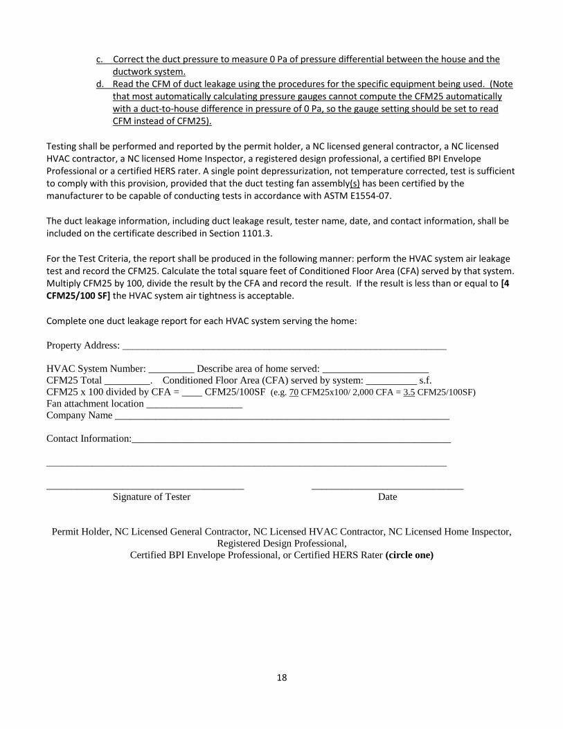
c. Correct the duct pressure to measure 0 Pa of pressure differential between the house and the ductwork system.
d. Read the CFM of duct leakage using the procedures for the specific equipment being used. (Note that most automatically calculating pressure gauges cannot compute the CFM25 automatically with a duct-to-house difference in pressure of 0 Pa, so the gauge setting should be set to read CFM instead of CFM25).
Testing shall be performed and reported by the permit holder, a NC licensed general contractor, a NC licensed HVAC contractor, a NC licensed Home Inspector, a registered design professional, a certified BPI Envelope Professional or a certified HERS rater. A single point depressurization, not temperature corrected, test is sufficient to comply with this provision, provided that the duct testing fan assembly(s) has been certified by the manufacturer to be capable of conducting tests in accordance with ASTM E1554-07.
The duct leakage information, including duct leakage result, tester name, date, and contact information, shall be included on the certificate described in Section 1101.3.
For the Test Criteria, the report shall be produced in the following manner: perform the HVAC system air leakage test and record the CFM25. Calculate the total square feet of Conditioned Floor Area (CFA) served by that system. Multiply CFM25 by 100, divide the result by the CFA and record the result. If the result is less than or equal to [4 CFM25/100 SF] the HVAC system air tightness is acceptable.
Complete one duct leakage report for each HVAC system serving the home: Property Address: ________________________________________________________________
HVAC System Number: _________ Describe area of home served: _____________________
CFM25 Total _________. Conditioned Floor Area (CFA) served by system: __________ s.f.
CFM25 x 100 divided by CFA = ____ CFM25/100SF (e.g. 70 CFM25x100/ 2,000 CFA = 3.5 CFM25/100SF)
Fan attachment location ___________________
Company Name __________________________________________________________________
Contact Information:_______________________________________________________________
_______________________________________________________________________________
_______________________________________ ______________________________
Signature of Tester Date
Permit Holder, NC Licensed General Contractor, NC Licensed HVAC Contractor, NC Licensed Home Inspector,
Registered Design Professional,
Certified BPI Envelope Professional, or Certified HERS Rater (circle one)