
ADM (Compact shelf) - Nokia Networks® ADM (Compact shelf) 1-1 ... STM-4 and STM-1 rings 3-13 Dual...
288
Metropolis ® ADM (Compact shelf) Application and Planning Guide Release 3.3 Lucent Technologies – Proprietary This document contains proprietary information of Lucent Technologies and is not to be disclosed or used except in accordance with applicable agreements Copyright © 2003 Lucent Technologies All Rights Reserved 365-312-739 CC109494302 Issue a October 2003
Transcript of ADM (Compact shelf) - Nokia Networks® ADM (Compact shelf) 1-1 ... STM-4 and STM-1 rings 3-13 Dual...
Metropolis® ADM (Compact shelf)Application and Planning Guide
Release 3.3
Lucent Technologies – ProprietaryThis document contains proprietary information
of Lucent Technologies and is not to be disclosed or usedexcept in accordance with applicable agreements
Copyright © 2003 Lucent TechnologiesAll Rights Reserved
365-312-739CC109494302
Issue aOctober 2003

Lucent Technologies – ProprietarySee notice on first page
365-312-739Issue a, October 2003
...........................................................................................................................................................................................................................................................
This material is protected by the copyright and trade secret laws of the United States and other countries. It may not be reproduced, distributed, or altered in any fashion by any entity (either internal or external to Lucent Technologies), except in accordance with applicable agreements, contracts or licensing, without the express written consent of Lucent Technologies and the business management owner of the material.
Lucent Learning WO +49 911 526 3315 or +49 911 526 2455
Notice
Every effort was made to ensure that the information in this document was complete and accurate at the time of printing. However, information is subject to change.
Trademarks
FrameMaker is a registered trademark of Adobe Systems, Inc.UNIX is a registered trademark of UNIX Systems Laboratories, Inc.HP-UX is a registered trademark of Hewlett-Packard, Inc.HP-VUE is a registered trademark of Hewlett-Packard, Inc.INFORMIX is a registered trademark of Informix Software, Inc.OSF/Motif is a registered trademark of Open Software Foundation.Microsoft and Windows are registered trademarks of Microsoft Corp.Netscape, Netscape Navigator and Netscape Communicator are trademarks of Netscape Communications Corp.Pentium is a trademark of Intel Corp.QuickTime is a registered trademarks of Apple Computer Inc.Adobe, Acrobat and PostScript are trademarks of Adobe Systems Inc.
WaveStar is a registered trademark of Lucent Technologies Inc.
All other copyrights, trademarks and tradenames are the property of their respective owners.
Limited warranty
Warranty, support and trouble escalation procedures have been established on a per country basis.
Contact your Lucent Technologies account representative for details.
Website
Lucent Technologies can be found at http://www.lucent.com/
Developed by Lucent Technologies Lucent Learning LL-WO
Contents
C O N T E N T Si i i
Lucent Technologies – ProprietaryUse pursuant to company instructions
365-312-739Issue a, October 2003
............................................................................................................................................................................................................................................................
About this information product
Purpose ix
Intended audience x
How to use this document x
Feature differences between R1.1. (Emerald) and R2.0 (Diamond) xii
Feature difference between R2.0 (Diamond) and R2.1 (Pearl) xiv
Feature difference between R2.1 (Pearl) and R2.1.x xv
Feature difference between R2.1 (Pearl) and R3.2 (Garnet) xvi
Feature difference between R3.2 (Garnet) and R3.3 (Garnet) xxiv
............................................................................................................................................................................................................................................................
1 Introduction
Metropolis® ADM (Compact shelf) 1-1
Applications 1-3
Concise System Description 1-4
............................................................................................................................................................................................................................................................
2 Features and Benefits
Overview 2-1
Standards Compliance 2-22-2
2-1
1-4
1-3
1-1
xxiv
xvi
xv
xiv
xii
x
x
ix
C O N T E N T Si v
365-312-739Issue a, October 2003
............................................................................................................................................................................................................................................................
Lucent Technologies – ProprietaryUse pursuant to company instructions
Features and Benefits 2-3
Protection mechanisms 2-4
Synchronization and Timing 2-6
Remote maintenance, management and control by Lucent Technologies Navis® Optical Management Solution Two-Tier Maintenance 2-8
Installation practice 2-10
Multi-service Application with WaveStar® TransLan® Card 2-11
............................................................................................................................................................................................................................................................
3 Applications
Overview 3-1
STM-16/STM-4 two fiber Add/Drop Terminalin rings applications 3-3
STM-4 LXC Applications 3-7
Broadcasting functionality 3-9
Payload Concatenation 3-10
Tributary interface mixing 3-12
Ring Closure: Single ADM interconnecting STM-16, STM-4 and STM-1 rings 3-13
Dual Node Interworking 3-14
SONET-SDH Conversion and Interworking 3-16
Multi-service Application with Wavestar® TransLan® Card 3-18
............................................................................................................................................................................................................................................................
4 Description
Introduction 4-2
Basic Metropolis® ADM (Compact shelf) Architecture 4-34-3
4-2
3-18
3-16
3-14
3-13
3-12
3-10
3-9
3-7
3-3
3-1
2-11
2-10
2-8
2-6
2-4
2-3
C O N T E N T Sv
365-312-739Issue a, October 2003
............................................................................................................................................................................................................................................................
Lucent Technologies – ProprietaryUse pursuant to company instructions
Shelf Complements 4-6
Paddle boards 4-7
Circuit packs 4-13
Timing and Synchronization 4-42
Redundancy and Protection 4-47
............................................................................................................................................................................................................................................................
5 Operations Administration Maintenance and Provisioning
Overview 5-1
Operations 5-2
Administration 5-8
Maintenance 5-13
Reports 5-15
Provisioning 5-17
............................................................................................................................................................................................................................................................
6 Cross-Product Interworking
Overview 6-1
Lucent Technologies SDH Product Family 6-2
Network systems 6-4
Navis® Optical Management Solution 6-10
............................................................................................................................................................................................................................................................
7 Physical design
Introduction 7-1
The Subrack 7-2
The printed circuit boards 7-47-4
7-2
7-1
6-10
6-4
6-2
6-1
5-17
5-15
5-13
5-8
5-2
5-1
4-47
4-42
4-13
4-7
4-6
C O N T E N T Sv i
365-312-739Issue a, October 2003
............................................................................................................................................................................................................................................................
Lucent Technologies – ProprietaryUse pursuant to company instructions
Paddle Boards 7-5
The interconnection systems 7-6
Cabling 7-10
............................................................................................................................................................................................................................................................
8 System Planning and Engineering
Overview 8-1
Network Planning 8-2
Network Synchronization 8-3
Metropolis® ADM (Compact shelf) SystemPlanning and Engineering 8-5
Position of Interface circuit packs in the Metropolis® ADM subrack 8-7
Paddle boards (electrical interfaces) 8-13
Configurations 8-16
............................................................................................................................................................................................................................................................
9 Technical Data
Overview 9-1
Interfaces 9-2
Power specification 9-8
Dimensions 9-9
System weight 9-10
Electrical connectors 9-11
Environmental specifications 9-12
General ITU recommendations 9-13
Mapping structure 9-149-14
9-13
9-12
9-11
9-10
9-9
9-8
9-2
9-1
8-16
8-13
8-7
8-5
8-3
8-2
8-1
7-10
7-6
7-5
C O N T E N T Sv i i
365-312-739Issue a, October 2003
............................................................................................................................................................................................................................................................
Lucent Technologies – ProprietaryUse pursuant to company instructions
Interfaces 9-16
Ethernet Interfaces 9-18
Timing and network synchronization 9-19
Transmission performance 9-20
Performance monitoring 9-21
OAM&P 9-22
Network management 9-23
Bandwidth management 9-24
Protection and redundancy 9-25
Overhead bytes processing 9-26
Metropolis® ADM (Compact shelf) Customer Documentation 9-27
............................................................................................................................................................................................................................................................
10 Quality and reliability
Overview 10-1
Lucent Technologies’ commitment to quality and reliability 10-2
Ensuring quality 10-3
Environmental aspects 10-4
Conformity statements 10-5
Reliability specifications 10-9
General specifications 10-10
Reliability program 10-11
Reliability specifications 10-1210-12
10-11
10-10
10-9
10-5
10-4
10-3
10-1
9-27
9-26
9-25
9-24
9-23
9-22
9-21
9-20
9-19
9-18
9-16
C O N T E N T Sv i i i
365-312-739Issue a, October 2003
............................................................................................................................................................................................................................................................
Lucent Technologies – ProprietaryUse pursuant to company instructions
............................................................................................................................................................................................................................................................
11 Product support
Overview 11-1
Installation Services 11-2
Engineering services 11-4
Maintenance services 11-7
Technical support 11-9
Documentation support 11-11
Training support 11-12
Training courses 11-13
............................................................................................................................................................................................................................................................
GL Glossary GL-1
11-13
11-12
11-11
11-9
11-7
11-4
11-2
11-1
i xLucent Technologies – Proprietary365-312-739Issue a, October 2003
..............................................................................................................................................................................................................................................................
About this information product
Purpose This Application and Planning Guide provides information about the features, applications, operation, engineering, support and specifications of the Metropolis® ADM (Compact shelf) multiplexer and transport system.
The Metropolis® ADM (Compact shelf) is a high-capacity, small footprint, intelligent multiplexer and transport system able to multiplex standard PDH and SDH bit rates as well as Ethernet signals to a higher level up to 2.5 Gbit/s (STM-16). This system is an useful and cost efficient element in building efficient and flexible networks because of its wide range in capacity and compact design.
The Metropolis® ADM (Compact shelf) system consists of one common hardware platform. This platform can serve a family of equipment and software configurations designed to support a particular set of applications.
These applications may be:
Two-fiber STM-16/STM-4 add/drop terminal in rings
STM-16/STM-4 access node
STM-16/STM-4 multiplexer with mixed E1 and ethernet access services
Payload concatenation:
• Virtual Concatenation on WaveStar® TransLan® Card
• Interconnecting ATM systems via VC-4-4c concatenation
Single ADM for interconnection of STM-16, STM-4 and STM-1 rings (ring closure)
x Lucent Technologies – Proprietary 365-312-739Issue a, October 2003
..............................................................................................................................................................................................................................................................
Dual Node Interconnection (DNI) with drop and continue
SONET-SDH conversion and interworking
Multi-Service applications with WaveStar® TransLan® Card, BASE-T and 1000BASE-X Ethernet.
In this Application and Planning Guide of the Metropolis® ADM (Compact shelf), all features are presented up to R3.2, Mercury release.
Intended audience This Application and Planning Guide is primarily for network planners and engineers. However, it is also useful for anyone who needs specific information about the features, applications, operation and engineering of the Metropolis® ADM (Compact shelf) Multiplexer and Transport System.
How to use this document This Guide is organized as follows
About this document: Describes the purpose, intended audience, and organization of this document. This section also references other related documentation.
Chapter 1, Introduction: This Chapter describes the Metropolis® ADM (Compact shelf).
Chapter 2, Features and Benefits: This chapter briefly describes the Features and Benefits of the Metropolis® ADM (Compact shelf). These are described in greater detail in Chapter 3 “Applications”, Chapter 4 “Product Description”, Chapter 5 “Operation, Administration, and Provisioning”, Chapter 6 “Physical design” as applicable.
Chapter 3, Applications: This chapter describes how the Metropolis® ADM (Compact shelf) platform meets various needs relating to network-level-specific topologies. In addition, it describes needs and provided functionality relating to various different applications such as point-to-point, ring, etc.
Also special system versions for applications in combination with other products of the Lucent Technologies family of SDH products are briefly discussed.
Chapter 4, Description: This chapter describes the Metropolis® ADM (Compact shelf) architecture. After an introduction of the Metropolis® ADM (Compact
x iLucent Technologies – Proprietary365-312-739Issue a, October 2003
..............................................................................................................................................................................................................................................................
shelf) platform, the system control, transmission, synchronization, protection and powering are described down to circuit pack level.
Chapter 5, Operation, Administration, Maintenance, and Provisioning: This chapter defines the “maintenance philosophy” outlining the various features available to monitor and maintain the Metropolis® ADM (Compact shelf).
Chapter 6, Cross-Product Interworking: This chapter briefly describes the interworking between the Metropolis® ADM (Compact shelf) and other products of Lucent Technologies’ SDH product family.
Chapter 7, Physical Design: This chapter describes the physical design, subrack, rack layouts and the connector panels of the Metropolis® ADM (Compact shelf).
Chapter 8, System Planning and Engineering: This chapter summarizes descriptive information used with the application information to plan procurement deployment of the Metropolis® ADM (Compact shelf).
Chapter 9, Technical Data: This chapter lists the detailed technical specifications for the Metropolis® ADM (Compact shelf).
Chapter 10, Quality and Reliability: This chapter describes Lucent Technologies’ quality policy and describes the reliability of the Metropolis® ADM (Compact shelf) in different configurations.
Chapter 11, Product Support: This chapter describes how Lucent Technologies supports the Metropolis® ADM (Compact shelf). This includes information about engineering and installation services, technical support, documentation support, and training.
Chapter 12, Glossary: This chapter lists in alphabetic order all the terms and acronyms used in the Application and Planning Guide.
x i i Lucent Technologies – Proprietary 365-312-739Issue a, October 2003
..............................................................................................................................................................................................................................................................
...............................................................................................................................................................................................................................................................Feature differences between R1.1. (Emerald) and R2.0 (Diamond)
In R2.0 the following features are added:
1. Configurable auto-negotiation on the WaveStar® TransLan® tributary card.
2. Support of mixed VC-12gX and VC-3gX connections on the WaveStar® TransLan® tributary card.
3. E3/DS3 tributary unit providing 12 switchable interfaces. 1+1 equipment protection is supported.
4. STM-1e tributary unit providing 4 interfaces including DCC support. 1+1 equipment protection is supported.
5. STM-4 tributary unit providing one interface S-4.1. MSP 1+1 protection supported according to G.841/Clause7.1.
6. STM-16 aggregate unit providing one L-16.2/3 interface. MSP 1+1 protection supported according to G.841/Clause7.1.
7. Centralized ITM-CIT alarming. The Metropolis® ADM (Compact shelf) supports a centralized alarm monitoring function on the ITM-CIT. After activation of this function via the ITM-CIT the NE always sends an autonomous alarm notification to the ITM-CIT after one or more alarms states have changed. The notification message also contains information if the NE is in an alarm free status or not. This Feature is also supported for networks with a mix of Metropolis® ADM (Compact shelf) and WaveStar® AM 1 (Plus). Autonomous alarm notifications are forwarded from both NE types to a single ITM-CIT.
8. Synchronization Performance Monitoring: PJE. The following parameters are available to estimate the synchronization performance:
• PJE-: Count of negative pointer justifications
• PJE+: Count of positive pointer justifications
Both counters are presented on one outgoing AU-4 pointer generation circuit per outgoing STM-N.
9. The Metropolis® ADM (Compact shelf) provides the numerical value, called NID (between 0 and 15 - corresponding with the 4 bits in the K-byte protocol as per ITU-T G.841) to the WaveStar® ITM-SC. The WaveStar® ITM-SC makes the event information available on the NB CORBA Interface.

x i i iLucent Technologies – Proprietary365-312-739Issue a, October 2003
..............................................................................................................................................................................................................................................................
10. Support of different size (ss-bit) support on STM-1/4/16 interfaces:
• In the source direction, the transmitted ss-bits can be provisioned in ‘10’ (SDH mode, default) or ‘00’ (SONET mode)
• In the sink direction the incoming ss-bits are ignored.
x i v Lucent Technologies – Proprietary 365-312-739Issue a, October 2003
..............................................................................................................................................................................................................................................................
...............................................................................................................................................................................................................................................................Feature difference between R2.0 (Diamond) and R2.1 (Pearl)
In R2.1 the following features are added:
1. Ethernet and Fast Ethernet VLAN Trunking: The system is able to aggregate Ethernet and/or Fast Ethernet traffic of multiple end-customers over a single external Ethernet /Fast Ethernet LAN port or internal WAN port. Such a VLAN Trunk port is a shared member of multiple VLANs from (potentially) different end-customers.
2. IEEE802.1Q VLAN Tagging (Ethernet/Fast Ethernet): The NE support VLAN Tagging, Classification and Filtering compliant to IEEE802.1Q on all of its external Ethernet LAN ports and internal WAN ports.
3. Support GVRP: The NE supports GARP VLAN Registration Protocol (GVRP) compliant with IEEE802.1Q clause 11.
4. Enhanced Rack Limits: In 2200 and 2600mm (300mm deep) racks, three systems with full 2 MBit/s, E3/DS3, STM-1e/o, STM-4o or LAN drop can be mounted. In 600mm depth racks, back to back mounting is possible to double the number of systems per rack.
5. Enhanced Paddle Board (75 ohm) for 2MBit/s interfaces: The PB-E1e/P75/63 unit is an extension of the PI-E1/75/63 and provides a compact high density paddle board. The advantage of this paddle board is the increased number of supported subracks per rack. Unprotected, 1:N protection applications and 75 ohm adaptation are supported.
6. Enhanced Paddle Board (120 ohm) for 2MBit/s interfaces: The PB-E1e/P120/63 unit is an extension of the PI-E1/120/63 and provides a compact high density paddle board. The advantage of this paddle board is the increased number of supported subracks per rack. Unprotected, 1:N protection applications and 120 ohm adaptation are supported.
7. STM-1 Long Haul Optical 1550 nm: A 155 MBit/s G.957/L-1.2/3 (~80km) long haul optical interface with an attenuation range from 10 to 28 dB (1x 10⁻¹⁰sensitivity) at an operating wavelength of 1550nm.
8. STM-4 Long Haul Optical 1550 nm: A 622 MBit/s G.957/L-4.2/3 (~80km) long haul optical interface with an attenuation range from 10 to 24 dB (1x 10⁻¹⁰sensitivity) at an operating wavelength of 1550nm.
x vLucent Technologies – Proprietary365-312-739Issue a, October 2003
..............................................................................................................................................................................................................................................................
...............................................................................................................................................................................................................................................................Feature difference between R2.1 (Pearl) and R2.1.x
In R2.1.x the following feature is added:
Support of IEEE802.1p QoS Full flexibility: This feature is an extension of Quality-Of-Service functions, introducing IEEE 802.1p flexible flow classification and scheduling to transmit network traffic from the switch in a predictable manner. The QoS functions contained in this feature are only applicable if the system operates according to IEEE802.1Q VLAN Tagging Ethernet/Fast Ethernet with 4 traffic class.
x v i Lucent Technologies – Proprietary 365-312-739Issue a, October 2003
..............................................................................................................................................................................................................................................................
...............................................................................................................................................................................................................................................................Feature difference between R2.1 (Pearl) and R3.2 (Garnet)
In R3.2 the following feature is added:
1. New CC/PT-64/32 core unit for STM-4 LXC applications. The new LKA15 is a cross-connect, power and timing unit without optics. This feature enables the tributary units to work as line interfaces. The LKA15 is placed in a line interface slot. This feature is supported by the Garnet Release WaveStar® ITM-SC R10.0.
2. New CC/PT-64/32 core units with two STM-4 ports. This new unit is available with the following interfaces.
2-port STM-4 1550nm LH (L-4.2
2-port STM-4 1310nm SH (S-4.1)
2-port mixed S-4.1/L-4.2 (HW 07/03)
There are two different MSP configurations possible:
MSP on one card (no card protection)
MSP between cards (with card protection)
The unit provides fully DCC, line timing and SNCP functionality. It is supported by WaveStar® ITM-SC R.11 and by Navis® NMS R.8.
3. New (PBP7) E1 Paddle board for 19-pin sub-D connector (HW 05/03) allowing locallized cabling.
4. 1000BASE-X Ethernet Tributary Card (FEP5879).
With R3.2 of the Metropolis® ADM (Compact shelf) an 1000BASE-X Ethernet Tributary Card is supported. The Gigabit Ethernet interface supports 1000BASE-SX optical interfaces (850 nm short haul, multimode) or 1000BASE-LX optical interfaces (1310 nm long haul, multimode or single mode) according IEEE 802.3 (2000 Edition) Clause 38. Full duplex only is supported. SX or LX applications can be selected by Small Formfactor Plugable module based Gigabit Ethernet interfaces.
Provisioning of Gigabit Ethernet mapping type for VLAN Trunking (single/dual LAN port, single card)One/two 1000BASE-X LAN interfaces, with access to the full WAN capacity of an EOS/GFP mapping device, can be provisioned as:
1 or 2 LAN ports, with
1 up to 8 WAN ports supporting an arbitrary mix of
x v i iLucent Technologies – Proprietary365-312-739Issue a, October 2003
..............................................................................................................................................................................................................................................................
VC-3, VC-3-1v, VC-3-2v (EOS or GFP mapped) and VC-4-1v, VC-4-2v, VC-4-3v, VC-4-4v (GFP mapped) type VC-groups, as long as the TDM slot/backplane capacity of the system is not exceeded
Provisioning of Gigabit Ethernet mapping type for GbE “lite” (single LAN port, single card)One 1000BASE-X LAN interface, with access to the full WAN capacity of an EOS/GFP mapping device, can be provisioned as:
1 LAN port, with
1 or 2 WAN ports containing an arbitrary mix of
VC-4-1v, VC-4-2v, VC-4-3v, VC-4-4v (GFP mapped) VC-groups, as long as the TDM slot/backplane capacity of the system is not exceeded. This is known as GbE “lite” (up to 600 Mb/s), or GbE “ultra-lite” packet ring (300 Mb/s).
Provisioning of Ethernet mapping type for WAN-to-WAN grooming/aggregation (single card)The system that supports a WAN-to-WAN grooming/aggregation function (no LAN ports) with access to the full WAN capacity of an EOS/GFP mapping device, can be provisioned as:
0 LAN ports,
1 up to 8 WAN ports with a grooming/aggregation capability of
VC-3 (EOS mapped) in VC-3-2v (GFP mapped) and/or VC-3, VC-3-Xv in VC-4-Xv type VC-groups, as long as the TDM slot/backplane capacity of the system is not exceeded.
This feature is known as VC-3 to VC-4 “grooming” and EOS to GFP “conversion”.
Mapping of Ethernet MAC frames into VC-4- Xv (GFP encapsulation)Ethernet MAC frames are mapped into/recovered from one, up to 4 VC-4's according to:
1000BASE-X «T1X1.5/2001-024r4 (ITU-T G.7041) protocol «C4-Xc «VC-4-Xv «X*VC-4 (X=1,.., 4). Generic Framing Procedure (GFP): Ethernet frame encapsulation scheme including adaptation from asynchronous Ethernet traffic to synchronous TDM traffic and frame delineation during damping.
x v i i i Lucent Technologies – Proprietary 365-312-739Issue a, October 2003
..............................................................................................................................................................................................................................................................
Mapping of Ethernet MAC frames into (LO) VC-3-Xv (GFP encapsulation)Ethernet MAC frames are mapped into/recovered from VC-3-1v or VC-3-2v according to:
WAN «T1X1.5/2001-024r4 (ITU-T G.7041) protocol «C3-Xc «VC-3-Xv «X*VC-3 (X=1,2).
Generic Framing Procedure (GFP): Ethernet frame encapsulation scheme including adaptation from asynchronous Ethernet traffic to synchronous TDM traffic and frame delineation during demapping. Note: this is the preferred mapping for VC-3.
Mapping of Ethernet MAC frames into (LO) VC-3-gv (EOS encapsulation) Ethernet MAC frames are mapped into/recovered from one or two VC-3's according to:
WAN «T1X1.5/99-268 (EOS) protocol «VC-3-gv «g*TU-3 «VC-4 (g=1,2). Note: This proprietary mapping is supported to provide interworking with systems that do not support GFP.
LAN bridge mode on Gigabit Ethernet HardwareThe Ethernet bridge function, according to IEEE802.1D, in the system supports per tributary unit:
Point to point LAN bridge
Multiport bridge up to and including 10 ports
MAC address filtering via self learning protocol (up to 64K MAC addresses)
Spanning-tree algorithm
Transparency to VLAN tagged packets from end customers
broadcasting, including end user BPDUs
LAN promiscuous mode on Gigabit Ethernet HardwareThe Ethernet bridge function in the system operates in promiscuous mode, forwarding all Ethernet frames it receives. This is only supported in point-to-point connections.
Multi-port LAN Bridging mode with L2 VPN support for Gigabit EthernetBased on the basic multiport switching functionality the NE supports an internal port-based VLAN packet tagging/untagging. This allows the setup of port based VPNs in a L2 network which is formed out of several independent Virtual
x i xLucent Technologies – Proprietary365-312-739Issue a, October 2003
..............................................................................................................................................................................................................................................................
Switches in different NEs which are interconnected by VC-4-Xv links. To setup a VPN relation between ports over the L2 network the operator has to assign a common VPN identifier (CID, which has to be unique within the whole L2 network) to each external Ethernet port which belongs to the same VPN and configure the related Virtual Switches into VPN mode. Multiple VPNs can be provisioned sharing the same L2 network infrastructure (shared bandwidth with statistical multiplexing) without any restrictions beside the fact that each external Ethernet port can be member of only one VPN at the same time. The maximum number of VPNs in a particular L2 network is limited by 256 or the total number of available external Ethernet ports in that L2 network and the fact that each VPN has to include at least 2 ports. Each VPN provides the functions independently from all other VPNs. A VPN with only two ports is also possible (e.g. transit hub node). Note: In case of data congestions towards a specific port packets is dropped from tail according their drop precedence marker.
Layer 2 VPN Data Policing, for Gigabit Ethernet In addition to the VPN support as described in Multi-port LAN Bridging mode with L2 VPN support, the Metropolis® ADM supports provisioning of data policing parameter at each external Ethernet port to allow L2 QoS and bandwidth management for each VPN of a L2 network.Each external Ethernet port of a switching relation in VPN mode can get assigned data policing parameter. The following parameters are supported:
Policing Mode with two possible values [Strict policing | Oversubscription] determined via provisioning a Peak Information Rate (PIR)
Committed Information Rate (CIR) per Port/User-Priority or Port/VLAN/User-Priority (Diamond release) relevant in both policing modes
In case of strict policing (PIR provisioned equal to CIR) all incoming packets from the associated external Ethernet port which exceed the provisioned CIR is dropped. In oversubscription mode (PIR provisioned above CIR) packets exceeding the CIR is marked by raising their drop precedence and only dropped if an congestion situation occurs during switching. This means that oversubscription mode allows a peak rate in the range of the physical line rate interconnecting the switches which are building the L2 network, but without any guaranteed bandwidth.
x x Lucent Technologies – Proprietary 365-312-739Issue a, October 2003
..............................................................................................................................................................................................................................................................
Note: It is the responsibility of the operator to ensure a suitable provisioning of CIR for each Ethernet port in relation to the underlaying L2 network topology to prohibit data congestions on any physical link which are interconnecting the switches of the network. With congestions the provisioned CIRs are not guaranteed.
Port-based VPN Customer Tagging, for Gigabit Ethernet (Transparent aka double tagging)The system allows to assign a Customer ID Tag (CID) to each external Ethernet LAN port. This CID is used to identify a VPN and isolate traffic from different end-customers over the WAN. For security reasons, it shall be unique within the whole WAN L2 network. CID can be configured in the range [0...4093] and retrieved via the EMS and/or CIT.
The CID is formatted into a VLAN Tag whose format is not fully compliant to IEEE 802.1Q Chapter 9. The system supports VLAN Tagging/Untagging mechanism as follows: each virtual bridge inserts VLAN/VPN Tag on all frames forwarded from an external Ethernet port to an internal WAN port and strips off the Tag in the reverse direction. This mechanism is transparent to the end-customer.
VPNs on transit nodes (no customer LAN port) are automatically instantiated during Spanning Tree protocol setup and do not require an explicit dynamic VPN Registration Protocol.
IEEE 802.1Q VLAN Tagging (Gigabit Ethernet) The NE supports VLAN Tagging, Classification and Filtering compliant to IEEE802.1Q on all of its external Gigabit Ether-net LAN ports and internal WAN ports. This Tagging mode is incompatible with Port-based VPN Customer Tagging.
The packets are processed as follows:
End-customer VLAN-tagged packets, received on external LAN ports or packets receive on a WAN port, are VLAN classified according to the VLAN Id contained in the VLAN Tag. The system performs VLAN Ingress filtering based on port membership of the receive port to the specific VLAN.
End-customer untagged and priority-tagged packets, received on external LAN ports, are VLAN classified according to a default Port VLAN Id (PVID identifying an end-customer as in Port Based VPN Customer Tagging) assigned to the receive port. The system inserts the PVID in the appended VLAN Tag.
x x iLucent Technologies – Proprietary365-312-739Issue a, October 2003
..............................................................................................................................................................................................................................................................
VLAN Id shall be unique among end-customers.
Note: This tagging scheme is incompatible with Port Based VPN Customer Tagging. For Interworking the same tagging scheme should be chosen on both ends of an WAN link.
Gigabit Ethernet VLAN Trunking The system is able to aggregate Gigabit Ethernet traffic of multiple end-customers over a single external Gigabit Ethernet LAN port or GbE WAN port. Such a VLAN Trunk port is a shared member of multiple VLANs from different end-customers. The VLAN Id list is configurable as in IEEE 802.1Q VLAN Tagging.
VLAN Trunking: Fast Ethernet WAN to Gigabit Ethernet LANThe system is able to aggregate Fast Ethernet traffic of multiple end-customers over a single external Gigabit Ethernet port. Such a VLAN Trunk port is a shared member of multiple VLANs from different end-customers. The VLAN Id list is configurable as in IEEE 802.1Q VLAN Tagging.
LCAS for Ethernet (1000BASE-X “lite”)The Metropolis® ADM supports the technique of Link Capacity Adjustment Scheme (LCAS), previously known as Variable Bandwidth Allocation (VBA), for Fast Ethernet transport. LCAS defines a synchronization protocol between two termination points of a virtual concatenated path that allows in-service dynamic sizing of the VC-n-Xv bandwidth available for Ethernet over SDH transmission. This bandwidth change can occur either in response to a failure condition on one member or a change in bandwidth requirement at a NE (provisioning action). In case of a failure, the bandwidth is restored automatically after the failure clears.
The size of the VC-4-Xv is increased or decreased in steps of VC-4 (X= 1,2,3,4). The provisioning is performed by connecting/disconnecting paths to/from the tributary Ethernet card.
The implementation is based on Nortel/Lucent contribution to T1X1.5/2000-199r1 (T1X1 T1.105 Section 7.3.4).
Performance Monitoring on LAN connections (Gigabit Ethernet ports)It is possible to monitor byte and packet related performance parameters on any external Ethernet port and any internal port linked with VC-3/4-Xv channels. The following counters are supported for each port:
x x i i Lucent Technologies – Proprietary 365-312-739Issue a, October 2003
..............................................................................................................................................................................................................................................................
Outgoing number of bytes
Incoming number of bytes
Number of incoming packets dropped
Accumulation of counts in 15 min. and 24 hour bins can be selected per port.Recent bins are stored: 16 recent 15 min. bins and 1 recent 24 hours bin.Thresholding (TR/RTR) on counts of dropped incoming packets can be enabled and configured per port.
New Ethernet Features
Extended Ethernet IEEE 802.3ac Frame size support for IEEE 802.1Q VLAN Tag (1522 bytes): Ethernet interfaces support reception and processing of frames sizes increased by a IEEE 802.1Q VLAN Tag, i.e.1522 bytes (max Untagged Frame Size + VLAN Tag Size), complying to IEEE 802.3ac supplement.
Extended Ethernet IEEE 802.3ac Frame size support for double IEEE 802.1Q VLAN Tags (1526 bytes): Ethernet interfaces support reception and processing of frames sizes increased by a second proprietary VLAN i.e. 1526 bytes.
Provisioning of VC-3-gv/VC-3-Xv Ethernet mapping type (EOS or GFP encapsulation). The system provides automatic detection of the mapping type, which can be over written by the user. The user has the option to provision the VC-3-gv/VC-3-Xv mapping type, of a system equipped with units for mixed VC-3/ VC-4 WAN interfaces, according to IEOS or GFP mapping.
Provisioning of VC-3-gv Ethernet mapping: The user has the option to provision 1 or 2 VC-3's to be used for transport of the frames, mapped according to: EOS encapsulation in VC-3-gv (VC-3 or VC-3-2v)
Provisioning of VC-3-Xv Ethernet: The user has the option to provision 1 or 2 VC-3's to be used for transport of the frames, mapped according to: GFP encapsulation in VC-3-Xv (VC-3-1v or VC-3-2v)
IEEE 802.1p QoS with VPN (double) Tagging: Full Flexibility: Same as IEEE 802.1p QoS but in the context of the double tagging scheme, the additional or different components supported at Ingress are:
x x i i iLucent Technologies – Proprietary365-312-739Issue a, October 2003
..............................................................................................................................................................................................................................................................
Flow segregation can be based on “User Priority” only,
Mapping of VLAN Tag user priority field or port default user priority into the user priority field of the second VPN Tag.
Policing per Flow with 'Oversubscription' capability (dropping precedence concept).
Rapid Spanning Tree Protocol according IEEE 802.1w. The Metropolis® ADM (Compact shelf) supports the fast converging version of Single STP per Virtual Switch, following IEEE P802.1w/D10
VC-3 enhanced C2 Signal label interpretation for Ethernet over SDH interworking. The signal label C2 contains information about the Ethernet over SDH mapping type. The system detects automatically whether the EOS (0x1F) or GFP (0x1B) mapping mode is used.
VC-4-Xv Overhead Access: H4 (Position Indicator) In case of data mapping over VC-4-Xv:Source direction: Each individual VC-4 (from the VC-4-Xv) H4-byte is written to indicate the values of the two-stage-multiframe indicator (timestamping), as well as the sequence indicator (individual VC-4 position inside a VC-4-Xv).
Sink direction: Each individual VC-4 (from the VC-4-Xv) H4-byte two-stage-multi-framing indicator and sequence indicator is used to check that the differential delay between the individual VC-4s of the VC-4-Xv remains within implementation limits.Usage is in conformance with ITU-T G.707 drafts
5. Enhanced Paddle Board (75 ohm) for 2MBit/s interfaces PBE5: The PB-E1/75/63 unit is an extension of the PI-E1/75/63 and provides a compact high density paddle board. The advantage of this paddle board is the increased number of supported subracks per rack. Unprotected applications and 75 ohm adaptation are supported.
6. Enhanced Paddle Board (120 ohm) for 2MBit/s interfaces PBE6: The PB-E1/120/63 unit is an extension of the PI-E1/120/63 and provides a compact high density paddle board. The advantage of this paddle board is the increased number of supported subracks per rack. Unprotected and 120 ohm adaptation are supported.

x x i v Lucent Technologies – Proprietary 365-312-739Issue a, October 2003
..............................................................................................................................................................................................................................................................
...............................................................................................................................................................................................................................................................Feature difference between R3.2 (Garnet) and R3.3 (Garnet)
In R3.3 the following features are added:
1. 1200 Performance Monitoring points
2. DS1 interface
3. GBE interface
4. WEEE regulation requirements
1 - 1Lucent Technologies – Proprietary365-312-739Issue a, October 2003
..............................................................................................................................................................................................................................................................
1 Introduction
...............................................................................................................................................................................................................................................................Metropolis® ADM (Compact shelf)
Overview The Metropolis® ADM (Compact shelf) is a high capacity, flexible, cost effective multiplexer and transport system able to multiplex standard PDH and SDH bit rates as well as Ethernet signals to a higher level up to 2.5 Gbit/s (STM-16). This system is an useful element in building efficient and flexible networks because of its wide range in capacity in addition to a compact and flexible design.
The main strengths of the product are:
Multi-service product for circuit- and packet based services
Massive add/drop capacity of up to:
• 252 x E1/DS1 (unprotected and protected)
• 48 x E3/DS3 (unprotected) or 24 x E3/DS3 (protected)
• 20 x STM-1o (unprotected) or 8 x STM-1o (protected)
• 16 x STM-1/e (unprotected and protected)
• 5 x STM-4o (unprotected) or 2 x STM-4o (protected)
• 32 x 10/100BASE-T Ethernet ports (unprotected)
• or 10 x 1000BASE-X Gigabit Ethernet ports (unprotected)
Compact design
Front access for all optical and electrical interfaces
Easy installation and maintenance
Low power dissipation
Introduction
1 - 2 Lucent Technologies – Proprietary 365-312-739Issue a, October 2003
..............................................................................................................................................................................................................................................................
Flexibility in applications and protection capabilities.
These features make the Metropolis® ADM (Compact shelf) one of the most cost-effective, future-proof and flexible network elements available on the market today.
Various protection mechanisms are supported by the Metropolis® ADM (Compact shelf), such as:
Multiplex Section Protection or MSP for STM-1o, STM-4o and STM-16o
Path protection or SNCP/N (Sub Network Connection Protection with Non Intrusive Monitoring) for higher- and lower order VCs
Multiplex Section Shared Protection Ring or MS-SPRing at STM-16 level
Dual Node Interconnection (DNI) with drop and continue
Like all network elements of Lucent Technologies SDH product portfolio, the Metropolis® ADM (Compact shelf) is managed by Lucent Technologies Navis® Optical Management Solution, a user-friendly network and element-level management system.
Introduction
1 - 3Lucent Technologies – Proprietary365-312-739Issue a, October 2003
..............................................................................................................................................................................................................................................................
...............................................................................................................................................................................................................................................................Applications
Overview The Metropolis® ADM (Compact shelf) supports a large variety of configurations for various network applications:
Two-fiber STM-16/STM-4 add/drop terminal in ring applications
STM-16/STM-4 Access node
Hybrid SDH with mixed E1/DS1 and Data access services
Single ADM for interconnection of STM-16, STM-4 and STM-1 rings (ring closure)
Sub Network Connection Protection in HO and LO VC
Dual Node Interconnection (DNI) with drop and continue with two MS-SPRing rings
Dual Node Interconnection (DNI) between MS-SPRing and LO-SNCP
Main applications of the system:
Grooming of lower order traffic in a ring
Path protected rings
Ring closure network element
ADM in MS-SPRing protected STM-16 rings.
The Ethernet LAN tributary card which is based on the Wavestar®
TransLan® Card, enables the Metropolis® ADM (Compact shelf) to provide Ethernet over SDH, and offers variable data applications on top of the traditional TDM applications.
Main applications of TransLan® are:
Direct LAN-LAN interconnect (two LAN’s)
Direct LAN-to-LAN interconnect (more than two LAN’s)
LAN-ISP interconnect
Multiple customers sharing a WAN connection
VLAN Trunking
TransLan® DCN engineering
Introduction
1 - 4 Lucent Technologies – Proprietary 365-312-739Issue a, October 2003
..............................................................................................................................................................................................................................................................
...............................................................................................................................................................................................................................................................Concise System Description
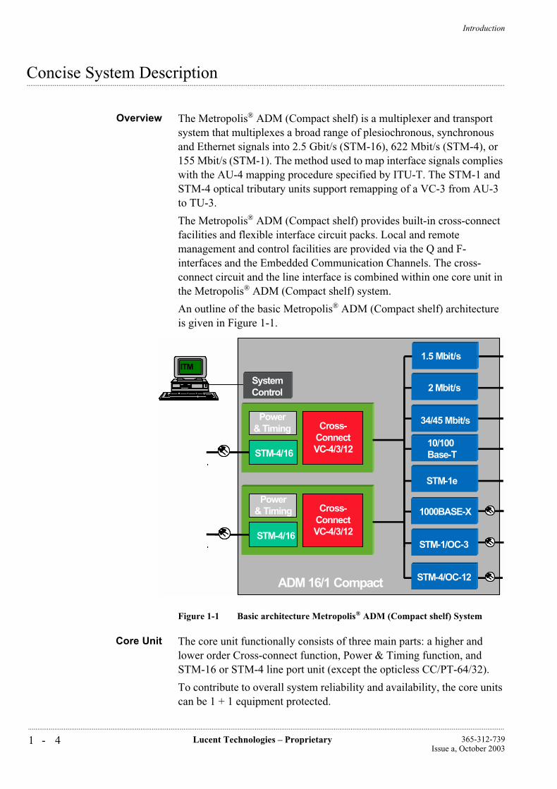
Overview The Metropolis® ADM (Compact shelf) is a multiplexer and transport system that multiplexes a broad range of plesiochronous, synchronous and Ethernet signals into 2.5 Gbit/s (STM-16), 622 Mbit/s (STM-4), or 155 Mbit/s (STM-1). The method used to map interface signals complies with the AU-4 mapping procedure specified by ITU-T. The STM-1 and STM-4 optical tributary units support remapping of a VC-3 from AU-3 to TU-3.
The Metropolis® ADM (Compact shelf) provides built-in cross-connect facilities and flexible interface circuit packs. Local and remote management and control facilities are provided via the Q and F-interfaces and the Embedded Communication Channels. The cross-connect circuit and the line interface is combined within one core unit in the Metropolis® ADM (Compact shelf) system.
An outline of the basic Metropolis® ADM (Compact shelf) architecture is given in Figure 1-1.
Figure 1-1 Basic architecture Metropolis® ADM (Compact shelf) System
Core Unit The core unit functionally consists of three main parts: a higher and lower order Cross-connect function, Power & Timing function, and STM-16 or STM-4 line port unit (except the opticless CC/PT-64/32).
To contribute to overall system reliability and availability, the core units can be 1 + 1 equipment protected.
1000BASE-X
SystemControl
ITM
Power& Timing
STM-4/16
Cross-ConnectVC-4/3/12
STM-1e
Power& Timing
STM-4/16
Cross-ConnectVC-4/3/12
10/100Base-T
STM-1/OC-3
2 Mbit/s
34/45 Mbit/s
ADM 16/1 Compact STM-4/OC-12
1.5 Mbit/s
1000BASE-X
SystemControl
ITMITM
Power& Timing
STM-4/16
Cross-ConnectVC-4/3/12
STM-1e
Power& Timing
STM-4/16
Cross-ConnectVC-4/3/12
10/100Base-T
STM-1/OC-3
2 Mbit/s
34/45 Mbit/s
ADM 16/1 Compact STM-4/OC-12
1.5 Mbit/s
Introduction
1 - 5Lucent Technologies – Proprietary365-312-739Issue a, October 2003
..............................................................................................................................................................................................................................................................
Cross-Connect The higher order cross-connect switches VC-4s. Other functions of the higher order cross-connect are: VC-4 SNC protection switching, MS-SPRing protection, MSP, equipment protection (see Chapter 2 for detailed explanations of mentioned protection mechanisms), non-intrusive monitoring of VC-4s and broadcasting.
The lower order cross-connect switches/grooms VC-3 and VC-12s. Other functions of the lower order cross-connect are: lower order SNCP protection, non-intrusive monitoring of lower order-VCs and lower order broadcasting.
Tributary circuit packs and line ports are directly connected to the higher order cross-connect via STM-1 equivalent signals.
Higher order and lower order cross-connect parts are interconnected via an internal cross-connect-bus. The lower order cross-connect itself is uni-directional, although traffic is switched/protected bi-directionally.
Higher order VC-4s arriving from line or tributary circuit packs need only to be routed through the lower order matrix, if the lower order VC content needs to be groomed. Otherwise, the VC-4 can be routed through the higher order cross-connect only!
Flexible routing and cross-connecting of VC-4, VC-3 and VC-12 between line port ⇔ line port, line port ⇔ tributary port and tributary port ⇔ tributary port is possible.
The system architecture makes it possible to use an interface circuit pack in almost any other slot position, hence the system becomes very flexible. A broad range of applications can be served with the same shelf based on a common software platform.
Power & Timing A basic function of the power and timing circuits is to filter and stabilize the incoming station power to meet the necessary ETSI requirements. The basic power distribution philosophy throughout the Metropolis® ADM (Compact shelf) is to equip each circuit pack with on-board DC/DC converters that convert the secondary (station battery) voltage to the voltages required for each circuit pack. The power feed from the station battery voltage is maintained duplicated throughout the system’s backplane.
Another basic function of the PT is system timing. The local oscillator, also called the SDH Equipment Clock (SEC), can be synchronized to one of the user-selectable timing references. For internal clock stability, Stratum-3 is used for the PT unit (see circuit packs in Chapter 4 for more details).
Interface circuit packs The Metropolis® ADM (Compact shelf) supports a large variety of interface circuit packs: 1.5, 2, 34/45, 155, 622Mbit/s, 10/100 Mbit/s BASE-T, 1000BASE-X and 2.5 Gbit/s. If required, interface redundancy
Introduction
1 - 6 Lucent Technologies – Proprietary 365-312-739Issue a, October 2003
..............................................................................................................................................................................................................................................................
can be provided. For details of these circuit packs, please refer to ‘circuit packs’ described in Chapter 4.
System control andnetwork management
The system controller (SC) controls and provisions all circuit packs via a local LAN bus. The SC also provides the external operations interfaces for office alarms, miscellaneous discretes and connections to the overhead channels (a maximum of 4 overhead bytes may be selected to be connected to 4 connectors on the backpanel).
The SC also facilitates first line maintenance by several LEDs and buttons on the front panel. General status and alarm information is displayed. Various controls and an F-interface connector, for a local maintenance PC (ITM-CIT), are also located on this panel.
The SC communicates with the centralized management system, Navis® Optical Management Solution (WaveStar® ITM-SC and Navis® Optical NMS).
A part of the SC, routing management information between SDH equipment and the element management system, is called data packet switch (DPS). Communication is established via so-called data communication channels (= D1-3/D4-12 bytes) (DCC), within the STM-N section overhead signals or va one of the Q-interfaces of the system. Information destined for the local system is routed to the System Controller, while other information is routed from the node via the appropriate embedded channels of the STM-N line or tributary signals.
The WaveStar® ITM-SC manages the Metropolis® ADM (Compact shelf) at the element level and the Navis® Optical NMS manages the system at the network level. For small networks a cost efficient manager by means of the ITM-CIT could be proposed supporting centralized alarming.
2 - 1Lucent Technologies – Proprietary365-312-739Issue a, October 2003
..............................................................................................................................................................................................................................................................
2 Features and Benefits
...............................................................................................................................................................................................................................................................Overview
Overview This chapter briefly describes the features and benefits of the Metropolis® ADM (Compact shelf). These features are further described in Chapter 3, “Applications”, Chapter 4, “Product Description” and Chapter 5, “Operation, Administration, Maintenance and Provisioning” as applicable.
Features and Benefits
2 - 2 Lucent Technologies – Proprietary 365-312-739Issue a, October 2003
..............................................................................................................................................................................................................................................................
...............................................................................................................................................................................................................................................................Standards Compliance
Standards Lucent Technologies SDH products comply with the relevant SDH ETSI and ITU-T standards. Important functions defined in SDH Standards such as the data communications Channel (DCC), the associated 7-layer OSI protocol stack, the SDH multiplexing structure and the Operations, Administration, Maintenance, and Provisioning (OAM&P) functions are implemented in the Lucent Technologies product family.
Jitter standards are also incorporated, guaranteeing a smooth interworking between PDH and SDH based networks. The full benefits of the SDH Standards are provided while preserving the integrity of the existing plesiochronous network.
Lucent Technologies is closely involved in various study groups with ITU-T and ETSI that focus on creating and maintaining the latest global SDH standards. The Metropolis® ADM (Compact shelf) complies with all relevant ETSI and ITU-T standards and is kept up to date according to the latest standards.
Features and Benefits
2 - 3Lucent Technologies – Proprietary365-312-739Issue a, October 2003
..............................................................................................................................................................................................................................................................
...............................................................................................................................................................................................................................................................Features and Benefits
Overview One of the main features of the Metropolis® ADM (Compact shelf) is its ability to add/drop and flexibly cross-connect 1.5Mbit/s or 2 Mbit/s directly from the aggregate level. Another attractive feature is that it can have the Ethernet connection directly to the SDH layer without any external DSU, which makes the total solution cheaper, easier and better for maintenance. Other signals that can be add/dropped are: 34, 45, 155 (STM-1), 622 (STM-4), 10/100BASE-T and 1000BASE-X.
Summary of main Features and Benefits described in this Chapter:
Protection mechanisms supported: MS SPRing, higher order & lower order SNC/N, MSP, Dual Node Interworking (DNI).
Synchronization and Timing:
Support of ETSI synchronization message protocol (Timing Marker)
Support of various synchronization modes, including 2 Mbit/s tributary timing.
Remote maintenance and management by Lucent Technologies Navis® Optical Management Solution (WaveStar® ITM-SC and Navis® Optical NMS)
Installation practice.
Ethernet LAN connection
Described in Chapter 3, Applications:
Single product platform for STM-16, STM-4, STM-1 and Data applications
Described in Chapter 4, System Description:
Equipment redundancy (all electrical interfaces, Core unit (including Cross-connect, Line port and power and timing unit).
Maximum Add/Drop capacity per shelf.VC-4, VC-3 and VC-12 Bi-directional cross-connect capability
Full Time Slot Assignment (TSA) for port interface signals and Time Slot Interchange (TSI) for through-channels
Mixing/Grooming of various payload types.
Features and Benefits
2 - 4 Lucent Technologies – Proprietary 365-312-739Issue a, October 2003
..............................................................................................................................................................................................................................................................
...............................................................................................................................................................................................................................................................Protection mechanisms
The Metropolis® ADM (Compact shelf) provides the following types of network level automatic transmission protection:
Point-to-Point MultiplexSection Protection (MSP)
A 1+1 MSP protection relation can be set up between a pair of STM-1 or STM-4 optical tributary interfaces. It is also possible to set up an MSP on a single 2 port STM-4 core unit. The applied protocol is according to G.841/clause 7.1. It supports both revertive and non-revertive operation and both uni-directional and bi-directional control. In addition, for this interface type interworking with SONET type MSP is supported in non-revertive operation with uni-directional control. See also Chapter 3.
VC-n SNC/N protectionswitching
Sub-network connection protection switching is selectable per VC using non-intrusive monitoring (SNC/N). This protection switching facility is non-revertive.
The VC-n SNC protection scheme is in essence a 1+1 point-to-point protection mechanism. The head end is dual fed (permanently bridged) and the tail end is switched. The switching criteria at the tail end are determined from the server layer defects in combination with the non-intrusive monitoring information.
SNC protection can be applied per individual VC-pair, for lower-order VCs the total number of VCs that can be SNC protected is limited only by the lower order cross-connect size (See Chapter 5).
SNC/N protects against:
• Server failures
• Open matrix connections (“unequipped signal”)
• An excessive number of bit errors (“signal degrade”)
• Misconnections (“trail trace identifier mismatch”).
Multiplex section sharedprotection ring protocol
(MS-SPRing)
In two fiber add/drop ring applications, the VC-4s on the STM-16 ring can be protected by the (selective) MS-SPRing protection mechanism. In 2-fiber add/drop ring applications, the VC-4 (-4c)'s in the ring can be protected by the MS-SPRing algorithm according to G.841 and ETS 300417. The user has the option to determine for each VC-4 (-4c) individually, whether or not it participates in the MS-SPRing scheme. If an individual VC-4 (-4c) does not participate then it can be either VC-4 (-4c) SNC protected or not protected at all.
Rings protected by MS-SPRing can have a maximum of 16 nodes. Within STM-16 MS-SPRing, channel #1 is protected by channel #9, #2 by #10, etc. up to #8 protected by #16. Each channel can be included in

Features and Benefits
2 - 5Lucent Technologies – Proprietary365-312-739Issue a, October 2003
..............................................................................................................................................................................................................................................................
or excluded from the MS-SPRing protection mechanism. Access to the protection channel capacity for “extra, low-priority traffic” is supported.
Dual node interworking(DNI) with drop and
continue (D&C)
The DNI with D&C scheme protects the interconnection between two subnetworks within which the traffic is already protected by a network protection scheme. The advantage of using DNI protection in a network is that there are no single point of failures anymore.
DNI is supported in the following cases:
between two MS-SPRing protected STM-16 rings.
between a MS-SPRing STM-16 ring and a lower order SNCP protected subnetwork.
Sub-networks without DNI protected interconnections can be upgraded in-service to have DNI protected interconnections.
The Metropolis® ADM (Compact shelf) supports the cascading of two protection schemes in one network element without needing multiple passes through cross-connects. The following schemes are cascadable:
MS-SPRing or MSP on aggregates and MSP on tributaries.
MS-SPRing or MSP on aggregates and LO-SNCP or HO-SNCP on tributaries.
MSP on tributaries and LO-SNCP or HO-SNCP on aggregates.
Two SNCP schemes on the same or different VC-n level.
Features and Benefits
2 - 6 Lucent Technologies – Proprietary 365-312-739Issue a, October 2003
..............................................................................................................................................................................................................................................................
...............................................................................................................................................................................................................................................................Synchronization and Timing
Several synchronization configurations can be used, the Metropolis® ADM (Compact shelf) can be provisioned for:
Free-running operation
Hold-over mode
Locked mode, internal SDH Equipment Clock (SEC) locked to:
One of the external sync inputs (2048 kHz or 2048 kbit/s)
One of the 2 Mbit/s tributary signals
One of the STM-N inputs (line or tributary port).
The user can select the external synchronization output to be locked to a suitable input signal independently of the selection made for the internal oscillator.
Frequency Offset Handling By comparing the frequencies of all assigned references with the frequencies of the internal oscillator on both timing units, it can be decided, in case an excessive frequency difference is detected, whether a reference is off-frequency on the internal oscillator of one of the timing units. In that case that unit is declared failed.
Timing Referenceprotection
The external timing references are non-revertively 1+1 protected. The external timing references can also operate unprotected.
Timing Mode protection If the primary timing reference fails, the system automatically switches over to the holdover mode. The synchronization status message is supported which enables timing reference priority settings and gives information about the timing-signal quality.
Synchronization StatusMessage support
A timing marker or synchronization status massage (SSM) signal can be used to transfer the signal quality level throughout a network. This guarantees that all network elements are always synchronized to the highest quality clock available.
On the Metropolis® ADM (Compact shelf) system the SSM algorithm or timing marker is supported according to G.781. SSM is supported on all STM-N interfaces and on the 2 Mbit/s synchronization output signal (connected to the station output clock).
2 Mbit/s tributary retiming The user can choose for individual 2 Mbit/s tributary outputs to operate “self-timed” or “re-synchronized”. In the (standard) self-timed mode, the phase of the outgoing signal is a moving average of the phase of the 2
Features and Benefits
2 - 7Lucent Technologies – Proprietary365-312-739Issue a, October 2003
..............................................................................................................................................................................................................................................................
Mbit/s signal as it is embedded in the VC-12 that is disassembled. In the re-synchronized mode the 2 Mbit/s signal is timed by the SDH Equipment Clock (SEC) of the network element; phase differences between the local clock and the 2 Mbit/s embedded in the VC-12 to be disassembled are accommodated by a slip-buffer.
There is an option that whenever the traceability of the local clock drops below a certain threshold; the re-timing 2 Mbit/s interfaces automatically switch to self-timing and vice-versa when the fail condition disappears, without hits in the traffic.
Features and Benefits
2 - 8 Lucent Technologies – Proprietary 365-312-739Issue a, October 2003
..............................................................................................................................................................................................................................................................
Remote maintenance, management and control by Lucent Technologies Navis® Optical Management Solution Two-Tier
...............................................................................................................................................................................................................................................................Maintenance
The Metropolis® ADM (Compact shelf) system maintenance procedures are built on two levels of system information and control. The first maintenance Tier consists of the user panel display (LEDs) and push buttons (all on the front of the system controller), and the circuit pack faceplate light-emitting diodes (LEDs). These allow most typical maintenance tasks to be performed without the ITM-Craft Interface Terminal (ITM-CIT) or element manager (WaveStar® ITM-SC).
The second maintenance tier employs the Lucent Technologies network management system. Detailed information and system control are obtained by using the ITM-CIT (Craft Interface Terminal), which supports provisioning, maintenance and configuration on a local basis. A similar facility is (via a Q-LAN connection or via the DCC channels) remotely available on the element manager, the WaveStar® ITM-SC, which provides a centralized maintenance view and supports maintenance activities from a central location.
At network level (customer’s network management center), Lucent Technologies’ Navis® Optical NMS system performs all the tasks necessary to supervise, operate, control and maintain an SDH network with the Metropolis® ADM (Compact shelf).
Operations Interfaces The Metropolis® ADM (Compact shelf) offers a wide range of operations interfaces to meet the needs of an evolving operations system (OS) network. The operation interfaces include:
Office Alarm Interfaces:This interface provides a set of discrete relays that control office audible and visible alarms.
User-settable miscellaneous discrete interfaces:This interface provides 8 user-selectable miscellaneous discrete inputs and 4 control outputs. These miscellaneous discrete inputs and outputs can be used to read the status of external alarm points and to drive external devices.
Two local workstation F interfaces:One RJ-45 F interfaces are provided, at the connection board of the Metropolis® ADM (Compact shelf). This interface provides operation access for a PC-based workstation also known as a Craft Interface Terminal (ITM-CIT).
Features and Benefits
2 - 9Lucent Technologies – Proprietary365-312-739Issue a, October 2003
..............................................................................................................................................................................................................................................................
Q interfaces:The Q-interfaces enable network-oriented communication between Metropolis® ADM (Compact shelf) systems and the element / network manager. This interface uses a Qx interface protocol compliant with ITU-T recommendation G.773-CLNS1 to provide the capability for remote management via the data communication channels (DCC).
A Q LAN 10Base-T (Twisted Pair Ethernet, for twisted pair cables) is used for Q interface. 9-pin sub-D connector is supported. For RJ-45 a conversion connector or cable is supported.
Single-Ended Operationsby WaveStar® ITM-SC
The WaveStar® ITM-SC Element Manager provides single-ended operations capability by remotely accessing all the Metropolis® ADM (Compact shelf) systems in a network from a single location. Operation, administration, maintenance and provisioning can be performed on a centralized location.
Local and Remote SoftwareUpgrades
The Metropolis® ADM (Compact shelf) System provides the capability to upgrade the system software in service without requiring any control circuit pack changes. The system monitoring and control are fully functional during the software download. Software is downloaded locally using the local ITM-CIT or remotely from the element manager via the Data Communication Channel (DCC).
Local and RemoteInventory capabilities
The Metropolis® ADM (Compact shelf) System provides automatic version recognition of all hardware and software installed in the system. Circuit pack types and circuit pack codes (‘comcodes’) are accessible via the local ITM-CIT or via the WaveStar® ITM-SC Element Manager. This greatly simplifies troubleshooting, dispatch decisions, and inventory audits.
Features and Benefits
2 - 1 0 Lucent Technologies – Proprietary 365-312-739Issue a, October 2003
..............................................................................................................................................................................................................................................................
...............................................................................................................................................................................................................................................................Installation practice
The Metropolis® ADM (Compact shelf) is housed in a self-supporting single-row shelf to fit in standard ETSI racks of 300 mm deep and 600mm width or in 19” racks. At maximum three Metropolis® ADM (Compact shelf) shelves without E1 tributaries fit in one 2200 mm high ETSI rack cabinet (HxWxD = 2200 x 600 x 300 mm) or 2600 mm high ETSI rack cabinet (HxWxD=2600 x 600 x 300). Two systems with E1 tributaries can be fit in one rack. The dimensions of the Metropolis® ADM (Compact shelf) shelf are: 925 x 450x 260 (HxWxD) mm with E1 tributary interfaces or 625 x 450 x 260 (HxWxD) mm without E1 tributary interfaces.
With the Enhanced Paddle Boards for 2MBit/s interfaces the following limits are applicable.
Enhanced Rack Limits: In 2200 and 2600mm (300 mm deep) racks, three systems with full1.5 Mbit/s, 2 MBit/s, E3/DS3, STM-1e/o, STM-4o or LAN drop can be mounted. In 600mm deep racks, back to back mounting is possible to double the number of systems per rack.
Installation restrictions can be found in Chapter 7 (cabling the Metropolis® ADM (Compact shelf)).
Features and Benefits
2 - 1 1Lucent Technologies – Proprietary365-312-739Issue a, October 2003
..............................................................................................................................................................................................................................................................
...............................................................................................................................................................................................................................................................Multi-service Application with WaveStar® TransLan® Card
The Metropolis® ADM (Compact shelf) provides LAN Ethernet tributary boards, based on the WaveStar ® TransLan® Card, which can provide a simple, managed solution for multiple-site LAN interconnection.
By mapping Ethernet frames into VC-12-xv, VC-3-xv or VC-4-xv the Metropolis® ADM (Compact shelf) can support various Ethernet connections, and provide an integrated data connection within a SDH network.
The main features of TransLan® are:
Ethernet LAN tributary board is according to IEEE 802.3 Ethernet
For 10/100BASE-T Ethernet frames are mapped into VC-12-xv (x=1,2...5) or VC-3-xv (x=1,2):
VC-12-xv (x=1...5) means 2Mbit/s, 4Mbit/s, 6Mbit/s, 8Mbit/s, 10Mbit/s
VC-3 and VC-3-v2 means 50Mbit/s and 100Mbit/s
For 1000BASE-X Ethernet frames are mapped into VC-3-xv (x=1 .. 2) or VC-4-xv (x=1 .. 4):
VC-3 and VC-3-v2 means 50Mbit/s and 100Mbit/s
VC-4-xv (x=1...4) means 150Mbit/s, 300Mbit/s, 450Mbit/s, 600Mbit/s
Multiple Operation Modes:
Repeater Mode for point to point operation
LAN-Interconnect Mode, dedicated WAN bandwidth for single end-user
LAN-VPN Mode, LAN Ports of multiple end-users share the same WAN port (s) bandwidth
LAN-VPN with IEEE 802.1p QoS Mode
Spanning Tree Virtual Switch Mode with IEEE 802.1Q VLAN Tagging
Ethernet/Fast Ethernet VLAN Trunking based on IEEE 802.1Q VLAN Tagging
GVRP according to IEEE 802.1Q, automatic provisioning of VLAN ID in intermediate nodes
Features and Benefits
2 - 1 2 Lucent Technologies – Proprietary 365-312-739Issue a, October 2003
..............................................................................................................................................................................................................................................................
Strict policing mode (PIR=CIR): Packets above PIR (peak Information Rate) are dropped at ingress LAN port immediately
Over subscription mode (PIR>CIR): Packets between CIR (Committed Information Rate) and PIR are marked of higher drop precedence
Spanning Tree Protocol, compliant to IEEE802.1D and IEEE802.1s, eliminates loops in bridged network
LCAS, for 1000BASE-X, allows in-service dynamic sizing of the VC-n-Xv. A bandwidth change can occur either in response to a failure condition on one member or a change in bandwidth requirement at a NE (provisioning action).
The main benefits of WaveStar ® TransLan® Card are:
Scalable bandwidth without having to change interface:
For the 10/100BASE-T interface, customers can choose VC-12-xv (x=1 .. 5) and VC-3-xv (x=1,2) and get the required bandwidth at 2,4,8,10,50 and 100Mbit/s.
For the 1000BASE-X interface, customer can choose VC-3-xv (x=1 .. 2) or VC-4-xv (x=1 .. 4) and get the required bandwidth at 50, 100, 150, 300, 450 and 600Mbit/s.
A transparent LAN service that hides the complexity of the WAN for end users (a WAN that looks like a LAN)
WAN access interface can be shared by other end-customers in a multi-tenant building environment
Provide end-to-end QoS (bandwidth, reliability) guaranteed when VPN path traveling through multiple network platforms (FR, ATM, IP)
Provide end-to-end interworking between VPN routers in a multi-vender environment.
High-availability LAN service by using end-to-end SDH protection switching
Increases revenue opportunities with packet service integration into SDH based network
Reduce cost of ownership by avoiding a separate overlay data network.
Features and Benefits
2 - 1 3Lucent Technologies – Proprietary365-312-739Issue a, October 2003
..............................................................................................................................................................................................................................................................
With VLAN trunk feature Wavestar® TransLan® cards can hand off end user LAN traffic via one high capacity LAN port instead of multiple low speed LAN ports, thus reducing port, space and cabling costs.

Features and Benefits
2 - 1 4 Lucent Technologies – Proprietary 365-312-739Issue a, October 2003
..............................................................................................................................................................................................................................................................
3 - 1Lucent Technologies – Proprietary365-312-739Issue a, October 2003
..............................................................................................................................................................................................................................................................
3 Applications
...............................................................................................................................................................................................................................................................Overview
The Metropolis® ADM (Compact shelf) is a single, highly flexible product that supports a variety of STM-16/STM-4 network applications.
Based on its flexibility with regard to interface circuit packs and cross-connect capabilities (see Chapter 4) the system supports a wide range of applications for bandwidth access, service-on-demand and network protection.
The Metropolis® ADM (Compact shelf) can be applied in all two tiers of a network, that is: Metro and Access. The system allows for growth and changing service needs by supporting in-service conversions and upgrades. Inherent to its basic design, the system operates equally well within fully synchronous as a-synchronous environments and provides a flexible link between the two.
The Metropolis® ADM (Compact shelf) supports a large variety of configurations for various network applications:
Two-fiber STM-16/STM-4 add/drop terminal in rings
STM-16/STM-4 access node
STM-16/STM-4 mux with mixed E1/DS1 and ethernet access service
Payload concatenation:
• Virtual Concatenation on WaveStar® TransLan® Card
• Interconnecting ATM systems via VC-4-4c concatenation
Applications
3 - 2 Lucent Technologies – Proprietary 365-312-739Issue a, October 2003
..............................................................................................................................................................................................................................................................
Single ADM for interconnection of STM-16, STM-4 and STM-1 rings (ring closure)
SONET-SDH conversion and interworking
Dual Node Interconnection (DNI) with drop and continue
Multi-Service applications with WaveStar® TransLan® Card, supporting 10/100BASE-T and 1000BASE-X Ethernet.
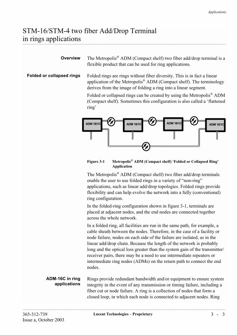
Applications
3 - 3Lucent Technologies – Proprietary365-312-739Issue a, October 2003
..............................................................................................................................................................................................................................................................
STM-16/STM-4 two fiber Add/Drop Terminal
...............................................................................................................................................................................................................................................................in rings applications
Overview The Metropolis® ADM (Compact shelf) two fiber add/drop terminal is a flexible product that can be used for ring applications.
Folded or collapsed rings Folded rings are rings without fiber diversity. This is in fact a linear application of the Metropolis® ADM (Compact shelf). The terminology derives from the image of folding a ring into a linear segment.
Folded or collapsed rings can be created by using the Metropolis® ADM (Compact shelf). Sometimes this configuration is also called a ‘flattened ring’
Figure 3-1 Metropolis® ADM (Compact shelf) ‘Folded or Collapsed Ring’ Application
The Metropolis® ADM (Compact shelf) two fiber add/drop terminals enable the user to use folded rings in a variety of “non-ring” applications, such as linear add/drop topologies. Folded rings provide flexibility and can help evolve the network into a fully (conventional) ring configuration.
In the folded-ring configuration shown in figure 3-1, terminals are placed at adjacent nodes, and the end nodes are connected together across the whole network.
In a folded ring, all facilities are run in the same path, for example, a cable sheath between the nodes. Therefore, in the case of a facility or node failure, nodes on each side of the failure are isolated, as in the linear add/drop chain. Because the length of the network is probably long and the optical loss greater than the system gain of the transmitter/receiver pairs, there may be a need to use intermediate repeaters or intermediate ring nodes (ADMs) on the return path to connect the end nodes.
ADM-16C in ringapplications
Rings provide redundant bandwidth and/or equipment to ensure system integrity in the event of any transmission or timing failure, including a fiber cut or node failure. A ring is a collection of nodes that form a closed loop, in which each node is connected to adjacent nodes. Ring
ADM 16/1CADM 16/1C ADM 16/1C ADM 16/1C
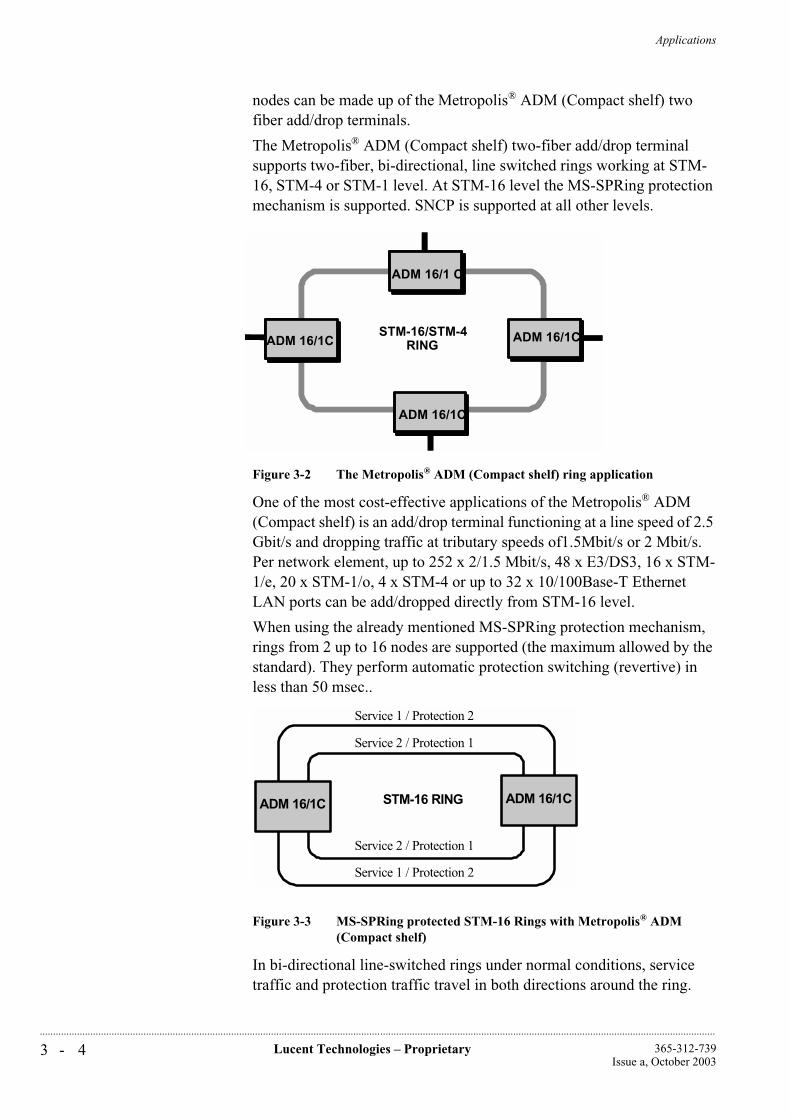
Applications
3 - 4 Lucent Technologies – Proprietary 365-312-739Issue a, October 2003
..............................................................................................................................................................................................................................................................
nodes can be made up of the Metropolis® ADM (Compact shelf) two fiber add/drop terminals.
The Metropolis® ADM (Compact shelf) two-fiber add/drop terminal supports two-fiber, bi-directional, line switched rings working at STM-16, STM-4 or STM-1 level. At STM-16 level the MS-SPRing protection mechanism is supported. SNCP is supported at all other levels.
Figure 3-2 The Metropolis® ADM (Compact shelf) ring application
One of the most cost-effective applications of the Metropolis® ADM (Compact shelf) is an add/drop terminal functioning at a line speed of 2.5 Gbit/s and dropping traffic at tributary speeds of1.5Mbit/s or 2 Mbit/s. Per network element, up to 252 x 2/1.5 Mbit/s, 48 x E3/DS3, 16 x STM-1/e, 20 x STM-1/o, 4 x STM-4 or up to 32 x 10/100Base-T Ethernet LAN ports can be add/dropped directly from STM-16 level.
When using the already mentioned MS-SPRing protection mechanism, rings from 2 up to 16 nodes are supported (the maximum allowed by the standard). They perform automatic protection switching (revertive) in less than 50 msec..
Figure 3-3 MS-SPRing protected STM-16 Rings with Metropolis® ADM (Compact shelf)
In bi-directional line-switched rings under normal conditions, service traffic and protection traffic travel in both directions around the ring.
ADM 16/1CADM 16/1CSTM-16/STM-4
RING
ADM 16/1 C
ADM 16/1C
ADM 16/1CADM 16/1CSTM-16/STM-4
RING
ADM 16/1 C
ADM 16/1C
Service 1 / Protection 2
Service 2 / Protection 1
Service 1 / Protection 2
Service 2 / Protection 1
STM-16 RINGADM 16/1C ADM 16/1C
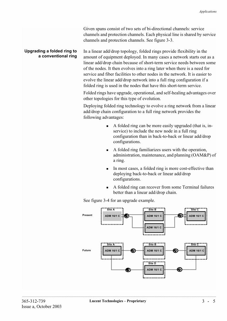
Applications
3 - 5Lucent Technologies – Proprietary365-312-739Issue a, October 2003
..............................................................................................................................................................................................................................................................
Given spans consist of two sets of bi-directional channels: service channels and protection channels. Each physical line is shared by service channels and protection channels. See figure 3-3.
Upgrading a folded ring toa conventional ring
In a linear add/drop topology, folded rings provide flexibility in the amount of equipment deployed. In many cases a network starts out as a linear add/drop chain because of short-term service needs between some of the nodes. It then evolves into a ring later when there is a need for service and fiber facilities to other nodes in the network. It is easier to evolve the linear add/drop network into a full ring configuration if a folded ring is used in the nodes that have this short-term service.
Folded rings have upgrade, operational, and self-healing advantages over other topologies for this type of evolution.
Deploying folded ring technology to evolve a ring network from a linear add/drop chain configuration to a full ring network provides the following advantages:
A folded ring can be more easily upgraded (that is, in-service) to include the new node in a full ring configuration than in back-to-back or linear add/drop configurations.
A folded ring familiarizes users with the operation, administration, maintenance, and planning (OAM&P) of a ring.
In most cases, a folded ring is more cost-effective than deploying back-to-back or linear add/drop configurations.
A folded ring can recover from some Terminal failures better than a linear add/drop chain.
See figure 3-4 for an upgrade example.
Site A Site B Site C
Site A Site B Site C
Site D
ADM 16/1 C
ADM 16/1 C
ADM 16/1 C ADM 16/1 C
ADM 16/1 C ADM 16/1 C ADM 16/1 C
ADM 16/1 C
Present
Future

Applications
3 - 6 Lucent Technologies – Proprietary 365-312-739Issue a, October 2003
..............................................................................................................................................................................................................................................................
Figure 3-4 Upgrade ‘Folded Ring’ to conventional ring
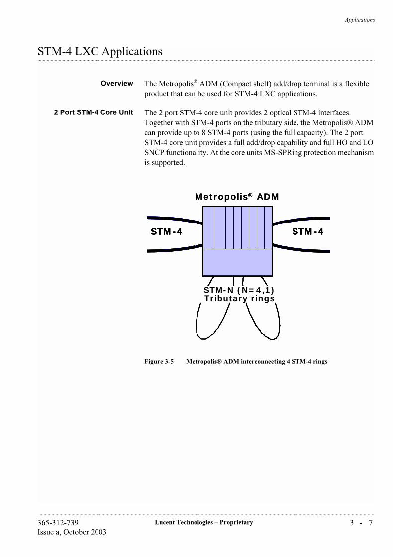
Applications
3 - 7Lucent Technologies – Proprietary365-312-739Issue a, October 2003
..............................................................................................................................................................................................................................................................
...............................................................................................................................................................................................................................................................STM-4 LXC Applications
Overview The Metropolis® ADM (Compact shelf) add/drop terminal is a flexible product that can be used for STM-4 LXC applications.
2 Port STM-4 Core Unit The 2 port STM-4 core unit provides 2 optical STM-4 interfaces. Together with STM-4 ports on the tributary side, the Metropolis® ADM can provide up to 8 STM-4 ports (using the full capacity). The 2 port STM-4 core unit provides a full add/drop capability and full HO and LO SNCP functionality. At the core units MS-SPRing protection mechanism is supported.
Figure 3-5 Metropolis® ADM interconnecting 4 STM-4 rings
STM-N (N=4,1)Tributary rings
STM-4
STM-N (N=4,1)Tributary rings
Metropolis® ADM
STM-4 STM-4STM-4
STM-N (N=4,1)Tributary rings
STM-4
STM-N (N=4,1)Tributary rings
Metropolis® ADM
STM-4 STM-4STM-4
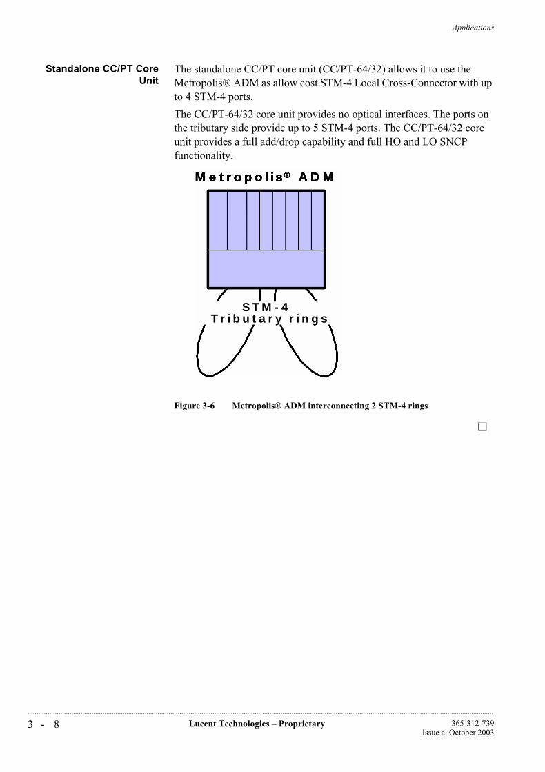
Applications
3 - 8 Lucent Technologies – Proprietary 365-312-739Issue a, October 2003
..............................................................................................................................................................................................................................................................
Standalone CC/PT CoreUnit
The standalone CC/PT core unit (CC/PT-64/32) allows it to use the Metropolis® ADM as allow cost STM-4 Local Cross-Connector with up to 4 STM-4 ports.
The CC/PT-64/32 core unit provides no optical interfaces. The ports on the tributary side provide up to 5 STM-4 ports. The CC/PT-64/32 core unit provides a full add/drop capability and full HO and LO SNCP functionality.
Figure 3-6 Metropolis® ADM interconnecting 2 STM-4 rings
Metropolis ADMMetropolis ADM
STM-N (N=4,1)Tributary rings
STM-N (N=4,1)Tributary rings
®
STM-N (N=4,1)Tributary rings
STM-4Tributary rings
®Metropolis ADMMetropolis ADM
STM-N (N=4,1)Tributary rings
STM-N (N=4,1)Tributary rings
®
STM-N (N=4,1)Tributary rings
STM-4Tributary rings
®
Applications
3 - 9Lucent Technologies – Proprietary365-312-739Issue a, October 2003
..............................................................................................................................................................................................................................................................
...............................................................................................................................................................................................................................................................Broadcasting functionality
The Metropolis® ADM (Compact shelf) has broadcast functionalities for VC-12, VC-3 and VC-4 containers. There are two broadcast modes possible, controlled by either the ITM-CIT (Craft Interface Terminal) or the Wavestar® ITM-SC (the element manager of the Metropolis® ADM (Compact shelf)):
Uni-directional 1:N broadcastA particular incoming VC is retransmitted in multiple (N = 2 to 9) directions. The return channels remain unused without generating any alarms.
1:2 broadcastThis is meant for test purposes. One of the directions of a bi-directional signal is broadcasted to an unused system output
Setting up or breaking down a broadcast direction does not affect the traffic in the other branches.
Applications
3 - 1 0 Lucent Technologies – Proprietary 365-312-739Issue a, October 2003
..............................................................................................................................................................................................................................................................
...............................................................................................................................................................................................................................................................Payload Concatenation
Overview Within the SDH standards there are two methods defined to create larger payload capacity than provided by a single VC11 (1.544 Mbit/s), VC-12 (2.176 Mbit/s), VC-2 (6.848 Mbit/s), VC-3 (53.760 Mbit/s) or VC-4 (149.760 Mbit/s). These methods are called “virtual concatenation” and “contiguous concatenation”. In both cases multiple VCs are taken together to create a bigger capacity transport pipe.
Virtual concatenation In the case of virtual concatenation, the payload is divided over multiple VCs, which are independently transported through the SDH network. The total transport entity in called VC-n-Xv, where the n is indicating the VC-type (n = 11, 12, 2, 3 or 4) and the X is denoting the number of VCs that are taken together to form a virtually concatenated signal. The v stands for “virtual”.
Each VC-n that is part of a VC-n-Xv structure has its own path overhead and its own corresponding TU-pointer, so each VC-n is transported independently over the SDH network between the VC-n-Xv termination points. The most popular options being considered are VC-12-Xv (X = 2,.., 63) and VC-2-Xv (X = 2,.., 21). For transport of these VC-n-Xv types it is required that all participating VC-n’s are located in the same VC-4.
On the Metropolis® ADM (Compact shelf) virtual concatenation is used on the Ethernet LAN tributary card which is based on the WaveStar® TranLAN™ Card. On the Ethernet LAN tributary board Ethernet frames are mapped into VC-12-xv (x=1,2...5) or VC-3-xv (x=1,2).
Contiguous concatenation Contiguous concatenation is only applicable at the VC-4 level. In this case the payload is divided over multiple VC4’s which are carried over the network as a single block, where the VC-4’s are mapped in adjacent AU-4 envelopes. This contiguous group of VC-4’s has only one single column of path overhead and also has a single pointer, which controls the phase of the complete block. Contiguously concatenated VC-4s are denoted as VC-4-Xc (X = 4, 16 or 64). The “c” indicates the fact that “contiguous” mapping is used.
To transport VC-4-Xc payloads through the SDH network, it is necessary that all SDH nodes that are passed through support this mapping. The Metropolis® ADM (Compact shelf) supports transport of VC-4-4c (payload capacity: 599.040 Mbit/s) via the STM-16/STM-4 aggregate interfaces and STM-4 tributary interfaces. The VC-4-4c payload can be added or dropped via the STM-4 tributary. In addition, protection of VC-4-4c is supported within the MS-SPRing protection scheme in an STM-16 ring. Also, SNC/N protection is supported to protect the add/drop path via the tributaries or in case MS-SPRing is not

Applications
3 - 1 1Lucent Technologies – Proprietary365-312-739Issue a, October 2003
..............................................................................................................................................................................................................................................................
used. Lastly, passing VC-4-4c’s can be non-intrusively monitored, both for faults and performance.
Applications
3 - 1 2 Lucent Technologies – Proprietary 365-312-739Issue a, October 2003
..............................................................................................................................................................................................................................................................
...............................................................................................................................................................................................................................................................Tributary interface mixing
The Metropolis® ADM (Compact shelf) supports a mix of 1.5, 2, 34, 45Mbit/s STM-1, STM-4 and 10/100Base-T tributary speed interface inputs and outputs. It is possible to mix these interfaces in the same subrack for all configurations. Also, a circuit can enter a Metropolis® ADM (Compact shelf) network through one type and exit through another type (if the payload that is being carried is compatible with both interface types).
These capabilities offer more efficient network evolution and allow planners to improve their equipment deployment based on the needs of the particular application.
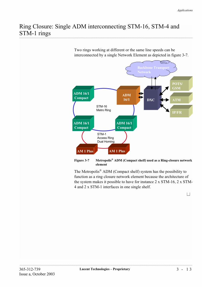
Applications
3 - 1 3Lucent Technologies – Proprietary365-312-739Issue a, October 2003
..............................................................................................................................................................................................................................................................
Ring Closure: Single ADM interconnecting STM-16, STM-4 and
...............................................................................................................................................................................................................................................................STM-1 rings
Two rings working at different or the same line speeds can be interconnected by a single Network Element as depicted in figure 3-7.
Figure 3-7 Metropolis® ADM (Compact shelf) used as a Ring-closure network element
The Metropolis® ADM (Compact shelf) system has the possibility to function as a ring closure network element because the architecture of the system makes it possible to have for instance 2 x STM-16, 2 x STM-4 and 2 x STM-1 interfaces in one single shelf.
STM-1Access RingDual Homing
Backbone TransportNetwork
DXC
IP/FR
ATM
POTS/GSM
ADM 16/1Compact
ADM 16/1Compact
ADM 16/1Compact
STM-16Metro Ring
ADM16/1
AM 1 Plus AM 1 Plus
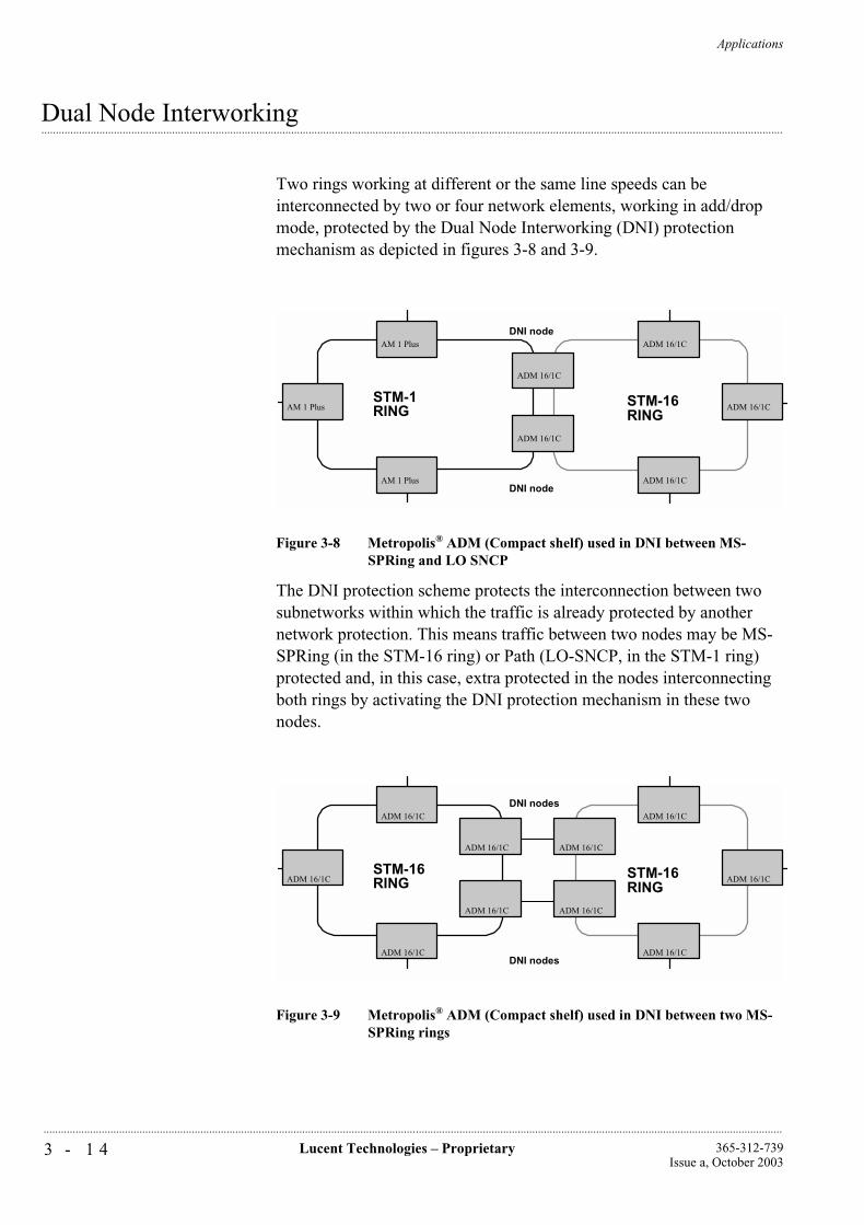
Applications
3 - 1 4 Lucent Technologies – Proprietary 365-312-739Issue a, October 2003
..............................................................................................................................................................................................................................................................
...............................................................................................................................................................................................................................................................Dual Node Interworking
Two rings working at different or the same line speeds can be interconnected by two or four network elements, working in add/drop mode, protected by the Dual Node Interworking (DNI) protection mechanism as depicted in figures 3-8 and 3-9.
Figure 3-8 Metropolis® ADM (Compact shelf) used in DNI between MS-SPRing and LO SNCP
The DNI protection scheme protects the interconnection between two subnetworks within which the traffic is already protected by another network protection. This means traffic between two nodes may be MS-SPRing (in the STM-16 ring) or Path (LO-SNCP, in the STM-1 ring) protected and, in this case, extra protected in the nodes interconnecting both rings by activating the DNI protection mechanism in these two nodes.
Figure 3-9 Metropolis® ADM (Compact shelf) used in DNI between two MS-SPRing rings
STM-1RING
STM-16RING
DNI node
DNI nodeADM 16/1C
AM 1 Plus
ADM 16/1C
ADM 16/1C
ADM 16/1C
ADM 16/1C
AM 1 Plus
AM 1 Plus
STM-16RING
STM-16RING
DNI nodes
DNI nodesADM 16/1C
ADM 16/1C
ADM 16/1C
ADM 16/1C ADM 16/1C
ADM 16/1C
ADM 16/1C
ADM 16/1C
ADM 16/1C
ADM 16/1C

Applications
3 - 1 5Lucent Technologies – Proprietary365-312-739Issue a, October 2003
..............................................................................................................................................................................................................................................................
The DNI protection scheme protects the interconnection between two subnetworks within which the traffic is already protected by MS-SPRing.
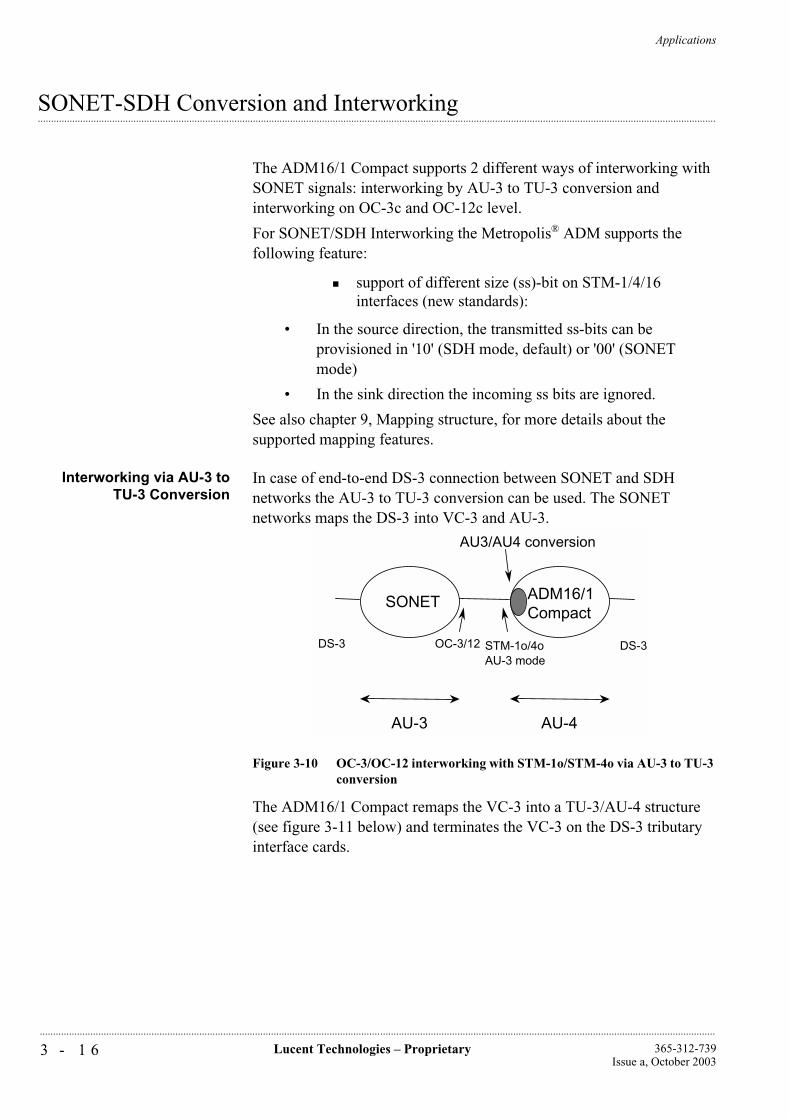
Applications
3 - 1 6 Lucent Technologies – Proprietary 365-312-739Issue a, October 2003
..............................................................................................................................................................................................................................................................
...............................................................................................................................................................................................................................................................SONET-SDH Conversion and Interworking
The ADM16/1 Compact supports 2 different ways of interworking with SONET signals: interworking by AU-3 to TU-3 conversion and interworking on OC-3c and OC-12c level.
For SONET/SDH Interworking the Metropolis® ADM supports the following feature:
support of different size (ss)-bit on STM-1/4/16 interfaces (new standards):
• In the source direction, the transmitted ss-bits can be provisioned in '10' (SDH mode, default) or '00' (SONET mode)
• In the sink direction the incoming ss bits are ignored.
See also chapter 9, Mapping structure, for more details about the supported mapping features.
Interworking via AU-3 toTU-3 Conversion
In case of end-to-end DS-3 connection between SONET and SDH networks the AU-3 to TU-3 conversion can be used. The SONET networks maps the DS-3 into VC-3 and AU-3.
Figure 3-10 OC-3/OC-12 interworking with STM-1o/STM-4o via AU-3 to TU-3 conversion
The ADM16/1 Compact remaps the VC-3 into a TU-3/AU-4 structure (see figure 3-11 below) and terminates the VC-3 on the DS-3 tributary interface cards.
ADM16/1Compact
SONET
STM-1o/4oAU-3 mode
OC-3/12
AU3/AU4 conversion
AU-3 AU-4
DS-3 DS-3
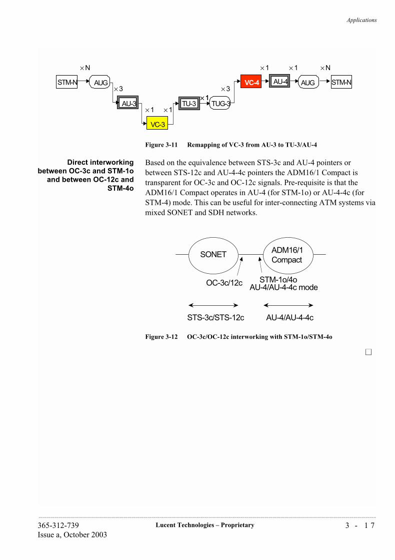
Applications
3 - 1 7Lucent Technologies – Proprietary365-312-739Issue a, October 2003
..............................................................................................................................................................................................................................................................
Figure 3-11 Remapping of VC-3 from AU-3 to TU-3/AU-4
Direct interworkingbetween OC-3c and STM-1o
and between OC-12c andSTM-4o
Based on the equivalence between STS-3c and AU-4 pointers or between STS-12c and AU-4-4c pointers the ADM16/1 Compact is transparent for OC-3c and OC-12c signals. Pre-requisite is that the ADM16/1 Compact operates in AU-4 (for STM-1o) or AU-4-4c (for STM-4) mode. This can be useful for inter-connecting ATM systems via mixed SONET and SDH networks.
Figure 3-12 OC-3c/OC-12c interworking with STM-1o/STM-4o
STM-N AUG
× N
AU-3 TUG-3TU-3
VC-4 AU-4 STM-NAUG
× N
× 3 × 3
× 1 × 1
× 1× 1
× 1 × 1
VC-3
ADM16/1Compact
SONET
STM-1o/4oAU-4/AU-4-4c modeOC-3c/12c
STS-3c/STS-12c AU-4/AU-4-4c

Applications
3 - 1 8 Lucent Technologies – Proprietary 365-312-739Issue a, October 2003
..............................................................................................................................................................................................................................................................
...............................................................................................................................................................................................................................................................Multi-service Application with Wavestar® TransLan® Card
The Ethernet LAN tributary card which is based on the Wavestar®
TransLan® Card, enables the Metropolis® ADM (Compact shelf) to provide Ethernet over SDH, and offers variable data applications on top of the traditional TDM applications. Therefore offers the customers cost-effective, simple and reliable multi-service solutions. TransLan® can provide VLAN function, and bandwidth can be shared for different customers.
Direct LAN-LANinterconnect (two LAN's)
The most straight-forward application of the Ethernet LAN tributary card is to interconnect two LAN segments that are at a distance that can not be reached with a simple Ethernet repeater, since that would violate the collision domain size rules. Both LAN's don’t have to be of the same speed. It is possible to interconnect 10BASE-T, 100BASE-TX and 1000BASE-X LANs this way. This application is shown at figure 3-13.
Figure 3-13 Example of direct LAN-LAN interconnections
Direct LAN-to-LANInterconnect (more than
two LAN's)
A next step in complexity is to interconnect multiple LAN's at different locations. It is possible to associate a single LAN port with two or more WAN ports. This way multiple sites can be interconnected, forming a
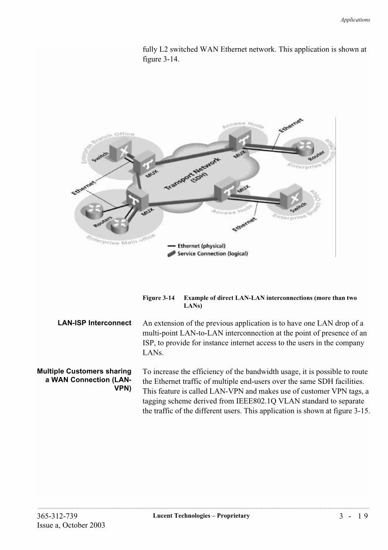
Applications
3 - 1 9Lucent Technologies – Proprietary365-312-739Issue a, October 2003
..............................................................................................................................................................................................................................................................
fully L2 switched WAN Ethernet network. This application is shown at figure 3-14.
Figure 3-14 Example of direct LAN-LAN interconnections (more than two LANs)
LAN-ISP Interconnect An extension of the previous application is to have one LAN drop of a multi-point LAN-to-LAN interconnection at the point of presence of an ISP, to provide for instance internet access to the users in the company LANs.
Multiple Customers sharinga WAN Connection (LAN-
VPN)
To increase the efficiency of the bandwidth usage, it is possible to route the Ethernet traffic of multiple end-users over the same SDH facilities. This feature is called LAN-VPN and makes use of customer VPN tags, a tagging scheme derived from IEEE802.1Q VLAN standard to separate the traffic of the different users. This application is shown at figure 3-15.
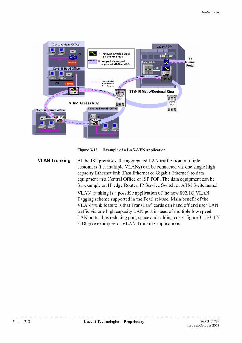
Applications
3 - 2 0 Lucent Technologies – Proprietary 365-312-739Issue a, October 2003
..............................................................................................................................................................................................................................................................
Figure 3-15 Example of a LAN-VPN application
VLAN Trunking At the ISP premises, the aggregated LAN traffic from multiple customers (i.e. multiple VLANs) can be connected via one single high capacity Ethernet link (Fast Ethernet or Gigabit Ethernet) to data equipment in a Central Office or ISP POP. The data equipment can be for example an IP edge Router, IP Service Switch or ATM Switchannel
VLAN trunking is a possible application of the new 802.1Q VLAN Tagging scheme supported in the Pearl release. Main benefit of the VLAN trunk feature is that TransLan® cards can hand off end user LAN traffic via one high capacity LAN port instead of multiple low speed LAN ports, thus reducing port, space and cabling costs. figure 3-16/3-17/3-18 give examples of VLAN Trunking applications.
CO or POPCO or POP
LAN
LAN
Digital Switch
PBXPBXE1 E1
N x E1
ConsolidatedB-to-B trafficfrom Corp. A
ADM16/1
STM-1 Access Ring
STM-16 Metro/Regional RingAM 1 Plus
LAN
PBXE1
ADM16/1
= LAN packets mapped in grouped VC-12s / VC-3s
= TransLAN Switch in ADM 16/1 and AM 1 Plus
Corp. A Branch OfficeCorp. A Branch Office
AM 1 Plus
ToInternetPortal
Corp. A Head OfficeCorp. A Head Office
Corp. A branch officeCorp. A branch office
AM 1 Plus
LAN
E1
Firewall
ADM16/1 C
ISPEdge Router
Firewall
PBX
Corp. B Head OfficeCorp. B Head Office
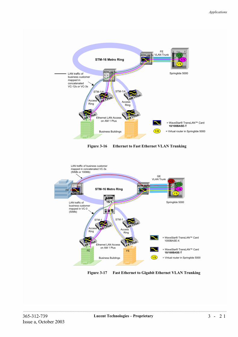
Applications
3 - 2 1Lucent Technologies – Proprietary365-312-739Issue a, October 2003
..............................................................................................................................................................................................................................................................
Figure 3-16 Ethernet to Fast Ethernet VLAN Trunking
Figure 3-17 Fast Ethernet to Gigabit Ethernet VLAN Trunking
VR
VRVR
STM-1/4 STM-1/4
STM-16 Metro Ring
Springtide 5000
Business Buildings
LAN traffic ofbusiness customermapped inconcatenatedVC-12s or VC-3s
FEVLAN Trunk
AccessRing
AccessRing
AM 1 Plus
AM 1 Plus
AM 1 Plus
AM 1 Plus
Ethernet LAN Accesson AM 1 Plus
VR
= WaveStar® TransLAN™ Card 10/100BASE-T
= Virtual router in Springtide 5000
ADM 16/1c
ADM 16/1c
VR
VRVR
ADM16/1
STM-1 STM-1
STM-16 Metro Ring
Springtide 5000
Business Buildings
LAN traffic ofbusiness customermapped in VC-3(50Mb)
GEVLAN Trunk
AccessRing
AccessRing
AM 1 Plus
AM 1 Plus
AM 1 Plus
AM 1 Plus
Ethernet LAN Accesson AM 1 Plus
VR
LAN traffic of business customermapped in concatenated VC-3s(50Mb or 100Mb)
FE
FE
FE
ADM 16/1c
VR = Virtual router in Springtide 5000
ADM 16/1c
= WaveStar® TransLAN™ Card 1000BASE-X
= WaveStar® TransLAN™ Card 10/100BASE-T
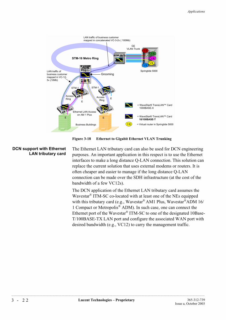
Applications
3 - 2 2 Lucent Technologies – Proprietary 365-312-739Issue a, October 2003
..............................................................................................................................................................................................................................................................
Figure 3-18 Ethernet to Gigabit Ethernet VLAN Trunking
DCN support with EthernetLAN tributary card
The Ethernet LAN tributary card can also be used for DCN engineering purposes. An important application in this respect is to use the Ethernet interfaces to make a long distance Q-LAN connection. This solution can replace the current solution that uses external modems or routers. It is often cheaper and easier to manage if the long distance Q-LAN connection can be made over the SDH infrastructure (at the cost of the bandwidth of a few VC12s).
The DCN application of the Ethernet LAN tributary card assumes the Wavestar® ITM-SC co-located with at least one of the NEs equipped with this tributary card (e.g., Wavestar® AM1 Plus, Wavestar®ADM 16/1 Compact or Metropolis® ADM). In such case, one can connect the Ethernet port of the Wavestar® ITM-SC to one of the designated 10Base-T/100BASE-TX LAN port and configure the associated WAN port with desired bandwidth (e.g., VC12) to carry the management traffic.
VR
VR
VR
STM-1 STM-1
STM-16 Metro Ring
Springtide 5000
Business Buildings
LAN traffic ofbusiness customermapped in VC-12-5v (10Mb)
GEVLAN Trunk
AccessRing
AccessRing
AM 1 Plus
AM 1 Plus
AM 1 Plus
Ethernet LAN Accesson AM 1 Plus
VR
LAN traffic of business customermapped in concatenated VC-3-2v ( 100Mb)
E E
ADM16/1
Grooming
E
AM 1 Plus
E
VR
VR = Virtual router in Springtide 5000
ADM 16/1c
= WaveStar® TransLAN™ Card 1000BASE-X
= WaveStar® TransLAN™ Card 10/100BASE-T
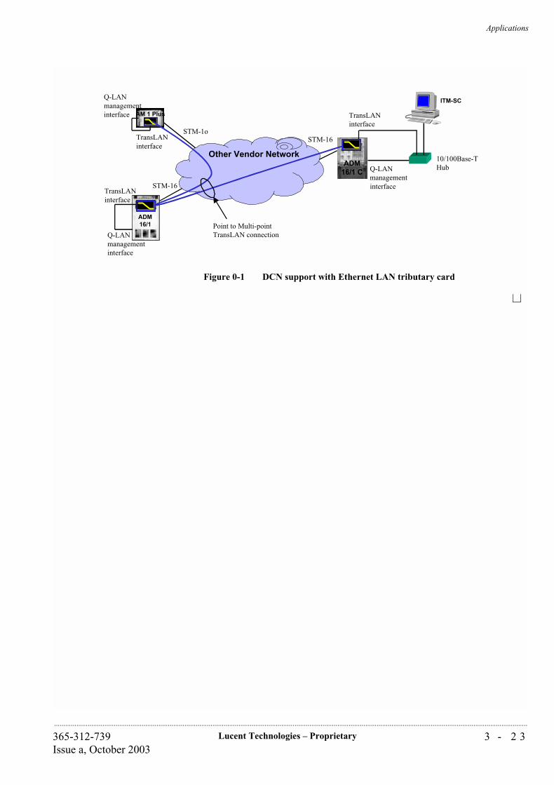
Applications
3 - 2 3Lucent Technologies – Proprietary365-312-739Issue a, October 2003
..............................................................................................................................................................................................................................................................
Figure 0-1 DCN support with Ethernet LAN tributary card
Other Vendor NetworkADM
16/1 C Q-LANmanagementinterface
ITM-SC
TransLANinterface
AM 1 Plus
STM-1o
STM-16
STM-16
Q-LANmanagementinterface
TransLANinterface
Q-LANmanagementinterface
TransLANinterface
ADM16/1 Point to Multi-point
TransLAN connection
10/100Base-THub

Lucent Technologies – ProprietarySee notice on first page
365-312-739Issue a, October 2003
...........................................................................................................................................................................................................................................................
Applications
4 - 1Lucent Technologies – Proprietary365-312-739Issue a, October 2003
..............................................................................................................................................................................................................................................................
4 Description
...............................................................................................................................................................................................................................................................Overview
This chapter provides a more detailed view of the system composition and the shelf complements of the Metropolis® ADM (Compact shelf). The system functions and circuit packs are described following the description of the system architecture, the partitioning of the circuit packs in the system, and the physical design. Additional information is provided relating to protection and timing architecture.

Description
4 - 2 Lucent Technologies – Proprietary 365-312-739Issue a, October 2003
..............................................................................................................................................................................................................................................................
...............................................................................................................................................................................................................................................................Introduction
This chapter describes the Metropolis® ADM (Compact shelf) in terms of basic architecture, physical configuration and circuit packs.
In addition, equipment redundancy and protection are briefly summarized.
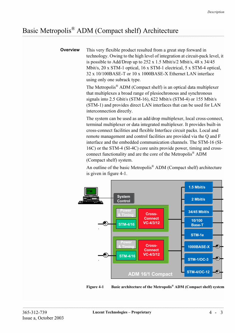
Description
4 - 3Lucent Technologies – Proprietary365-312-739Issue a, October 2003
..............................................................................................................................................................................................................................................................
...............................................................................................................................................................................................................................................................Basic Metropolis® ADM (Compact shelf) Architecture
Overview This very flexible product resulted from a great step forward in technology. Owing to the high level of integration at circuit-pack level, it is possible to Add/Drop up to 252 x 1.5 Mbit/s/2 Mbit/s, 48 x 34/45 Mbit/s, 20 x STM-1 optical, 16 x STM-1 electrical, 5 x STM-4 optical, 32 x 10/100BASE-T or 10 x 1000BASE-X Ethernet LAN interface using only one subrack type.
The Metropolis® ADM (Compact shelf) is an optical data multiplexer that multiplexes a broad range of plesiochronous and synchronous signals into 2.5 Gbit/s (STM-16), 622 Mbit/s (STM-4) or 155 Mbit/s (STM-1) and provides direct LAN interfaces that can be used for LAN interconnection directly.
The system can be used as an add/drop multiplexer, local cross-connect, terminal multiplexer or data integrated multiplexer. It provides built-in cross-connect facilities and flexible Interface circuit packs. Local and remote management and control facilities are provided via the Q and F interface and the embedded communication channels. The STM-16 (SI-16C) or the STM-4 (SI-4C) core units provide power, timing and cross-connect functionality and are the core of the Metropolis® ADM (Compact shelf) system.
An outline of the basic Metropolis® ADM (Compact shelf) architecture is given in figure 4-1.
Figure 4-1 Basic architecture of the Metropolis® ADM (Compact shelf) system
1000BASE-X
SystemControl
ITM
Power& Timing
STM-4/16
Cross-ConnectVC-4/3/12
STM-1e
Power& Timing
STM-4/16
Cross-ConnectVC-4/3/12
10/100Base-T
STM-1/OC-3
2 Mbit/s
34/45 Mbit/s
ADM 16/1 Compact STM-4/OC-12
1.5 Mbit/s
1000BASE-X
SystemControl
ITMITM
Power& Timing
STM-4/16
Cross-ConnectVC-4/3/12
STM-1e
Power& Timing
STM-4/16
Cross-ConnectVC-4/3/12
10/100Base-T
STM-1/OC-3
2 Mbit/s
34/45 Mbit/s
ADM 16/1 Compact STM-4/OC-12
1.5 Mbit/s
Description
4 - 4 Lucent Technologies – Proprietary 365-312-739Issue a, October 2003
..............................................................................................................................................................................................................................................................
SI-16C The SI-16C circuit pack functionally consists of three parts: a cross-connect unit that has a higher and a lower order cross-connect, a Power and Timing unit and a STM-16 Line interface.
SI-4C The SI-4C circuit pack contains the same functionality as the SI-16C but it has 2 STM-4 Line ports.
Standalone Core Unit The CC/PT-64/32 core unit provides a higher and a lower order cross-connect, Power and Timing but it has no interface ports.
Cross-connect The higher order cross-connect switches VC-4s. Other functions of the higher order cross-connect are: VC-4 SNC protection switching, MS-SPRing protection, MSP, equipment protection of tributary slots (see at the end of this Chapter and at Chapter 2 for detailed explanations of mentioned protection mechanisms), non-intrusive monitoring of VC-4s and broadcasting.
The lower order cross-connect switches/grooms VC-3 and VC-12s. Other functions of the lower order cross-connect are: lower order SNCP protection, non-intrusive monitoring of lower order VCs and lower order broadcasting.
Tributary and line interfaces circuit packs are directly connected to the higher order cross-connect via STM-1 equivalent signals.
Higher- and lower order cross-connect parts are interconnected via an internal cross-connect-bus. The lower order cross-connect itself is uni-directional although traffic can be switched/protected bi-directionally (= default situation).
Higher order VC-4s arriving from line or tributary circuit packs need only to be routed through the lower order matrix, if the lower order VC content needs to be groomed. Otherwise, the VC-4 can be routed through the higher order cross-connect only.
Flexible routing and cross-connecting of VC-4, VC-3 and VC-12 between line port ⇔ line port, line port ⇔ tributary port and tributary port ⇔ tributary port is possible.
The system architecture makes it possible to use an interface circuit pack in almost any other slot position, hence the system becomes very flexible. A broad range of applications can be served with the same shelf based on a common software platform.
To contribute to overall system reliability and availability, the core unit can be 1+1 equipment protected by an accompanying circuit pack.
Power A basic function of the core unit is to filter and stabilize the incoming station power in order to meet the necessary ETSI requirements. The basic power distribution philosophy throughout the Metropolis® ADM (Compact shelf) is to equip each circuit pack with on-board DC/DC

Description
4 - 5Lucent Technologies – Proprietary365-312-739Issue a, October 2003
..............................................................................................................................................................................................................................................................
converters that convert the customer's secondary (station battery) voltage to the voltages required for each circuit pack. The power feed from the station battery voltage is maintained duplicated throughout the system’s backplane.
Timing Another basic function of the core unit is system timing. The local oscillator, also called the SDH equipment clock (SEC), can be synchronized to one of the user-selectable timing references. The timing function has a hold-over stability of ±0.37 ppm (Stratum-3).
Interface circuit packs The Metropolis® ADM (Compact shelf) supports a large variety of interface types: 2MBit/s, 34MBit/s, 45MBit/s, 10/100Base-T Ethernet, STM-1 electrical, STM-1 optical, STM-4 and STM-16 are the circuit packs that can be used. If required, interface redundancy can be provided. For details of these circuit packs please refer to ‘circuit packs’ described later in this chapter.
System control andmanagement
The System controller (SC) controls and provisions all circuit packs via a local LAN bus. The SC also provides the external operations interfaces for office alarms, miscellaneous discretes and connections to the overhead channels (a maximum of four overhead bytes may be selected to be connected to four connectors on the interconnection panel).
The SC also facilitates first line maintenance by several LEDs and buttons on the front panel. General status and alarm information is displayed. Various controls and an F-interface connector, for a local maintenance PC (ITM-CIT), are also located on this panel.
The SC communicates with the centralized management system (WaveStar® ITM-SC and Navis® Optical NMS).
A part of the SC, routing management information between SDH equipment and the element management system, is called data packet switch (DPS). Communication is established via so-called data communication channels (DCC) (= D1-3/D4-12 bytes), within the STM-N section overhead signals or via one of the Q-interfaces of the system. Information destined for the local system is routed to the System Controller, while other information is routed from the node via the appropriate embedded channels of the STM-N line or tributary signals.
The WaveStar® ITM-SC manages the Metropolis® ADM (Compact shelf) at the element level and the Navis® Optical NMS manages the system at the network level. The ITM-Craft Interface Terminal (ITM-CIT) can be used for managing small networks and for maintenance.
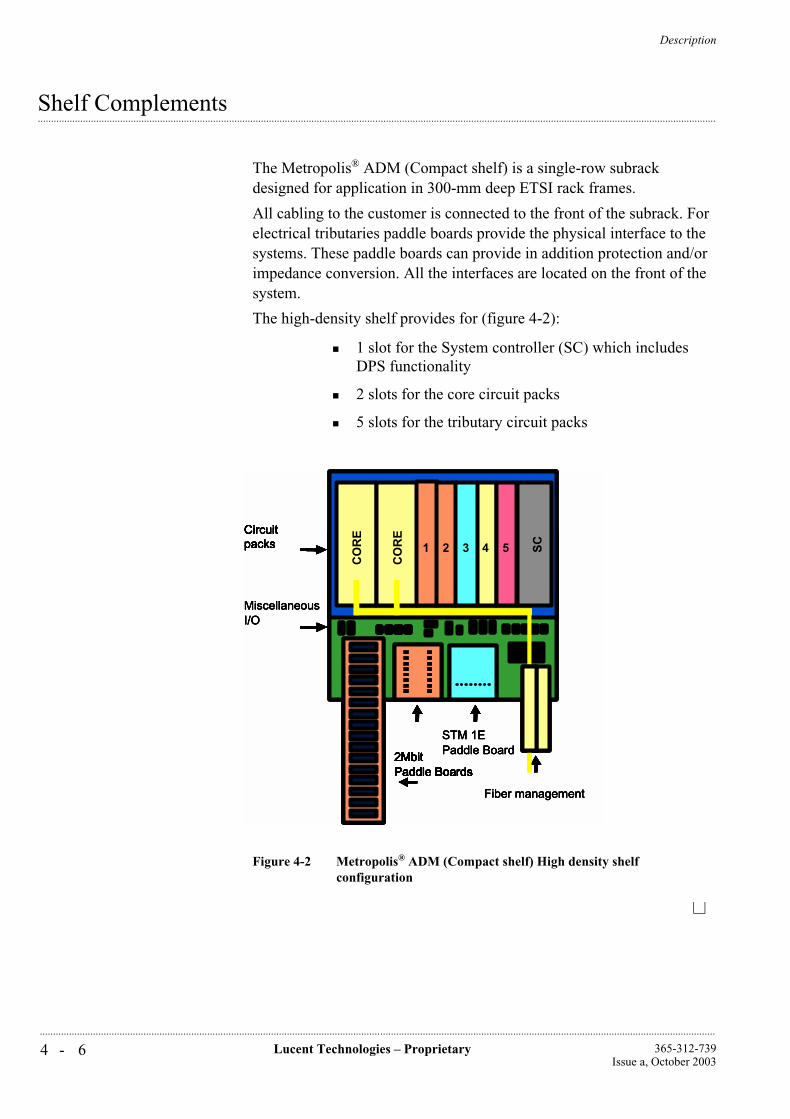
Description
4 - 6 Lucent Technologies – Proprietary 365-312-739Issue a, October 2003
..............................................................................................................................................................................................................................................................
...............................................................................................................................................................................................................................................................Shelf Complements
The Metropolis® ADM (Compact shelf) is a single-row subrack designed for application in 300-mm deep ETSI rack frames.
All cabling to the customer is connected to the front of the subrack. For electrical tributaries paddle boards provide the physical interface to the systems. These paddle boards can provide in addition protection and/or impedance conversion. All the interfaces are located on the front of the system.
The high-density shelf provides for (figure 4-2):
1 slot for the System controller (SC) which includes DPS functionality
2 slots for the core circuit packs
5 slots for the tributary circuit packs
Figure 4-2 Metropolis® ADM (Compact shelf) High density shelf configuration
ST
M1O
4
Co
re
Co
re 1
TS
1
2 3 5
2MbitPaddle Boards
STM 1EPaddle Board
Fiber management
MiscellaneousI/O
Circuitpacks S
CST
M1O
4
CO
RE
CO
RE
1
TS
1
2 3 5
2MbitPaddle Boards2MbitPaddle Boards2MbitPaddle Boards
STM 1EPaddle Board
Fiber management
MiscellaneousI/O
CircuitpacksCircuitpacks S
CST
M1O
4
Co
re
Co
re 1
TS
1
2 3 5
2MbitPaddle Boards2MbitPaddle Boards2MbitPaddle Boards
STM 1EPaddle Board
Fiber management
MiscellaneousI/O
CircuitpacksCircuitpacks S
CST
M1O
4
CO
RE
CO
RE
1
TS
1
2 3 5
2MbitPaddle Boards2MbitPaddle Boards2MbitPaddle Boards2MbitPaddle Boards
STM 1EPaddle Board
Fiber management
MiscellaneousI/O
CircuitpacksCircuitpacks S
C
Description
4 - 7Lucent Technologies – Proprietary365-312-739Issue a, October 2003
..............................................................................................................................................................................................................................................................
...............................................................................................................................................................................................................................................................Paddle boards
A variety of paddle boards exists for connection between customer cabling and the backplane in case of protection or impedance conversion. All paddle boards can be inserted from front of the equipment and fit on the 2 mm-pitch backplane connectors.
The paddle boards contain the hardware to adjust the impedance or to provide equipment protection.
Paddle boards for 1.5/2 Mbit/s:
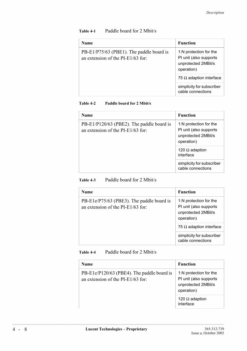
Description
4 - 8 Lucent Technologies – Proprietary 365-312-739Issue a, October 2003
..............................................................................................................................................................................................................................................................
Table 4-1 Paddle board for 2 Mbit/s
Table 4-2 Paddle board for 2 Mbit/s
Table 4-3 Paddle board for 2 Mbit/s
Table 4-4 Paddle board for 2 Mbit/s
Name Function
PB-E1/P75/63 (PBE1). The paddle board is an extension of the PI-E1/63 for:
1:N protection for the PI unit (also supports unprotected 2MBit/s operation)
75 Ω adaption interface
simplicity for subscriber cable connections
Name Function
PB-E1/P120/63 (PBE2). The paddle board is an extension of the PI-E1/63 for:
1:N protection for the PI unit (also supports unprotected 2MBit/s operation)
120 Ω adaption interface
simplicity for subscriber cable connections
Name Function
PB-E1e/P75/63 (PBE3). The paddle board is an extension of the PI-E1/63 for:
1:N protection for the PI unit (also supports unprotected 2MBit/s operation)
75 Ω adaption interface
simplicity for subscriber cable connections
Name Function
PB-E1e/P120/63 (PBE4). The paddle board is an extension of the PI-E1/63 for:
1:N protection for the PI unit (also supports unprotected 2MBit/s operation)
120 Ω adaption interface

Description
4 - 9Lucent Technologies – Proprietary365-312-739Issue a, October 2003
..............................................................................................................................................................................................................................................................
simplicity for subscriber cable connections
Name Function
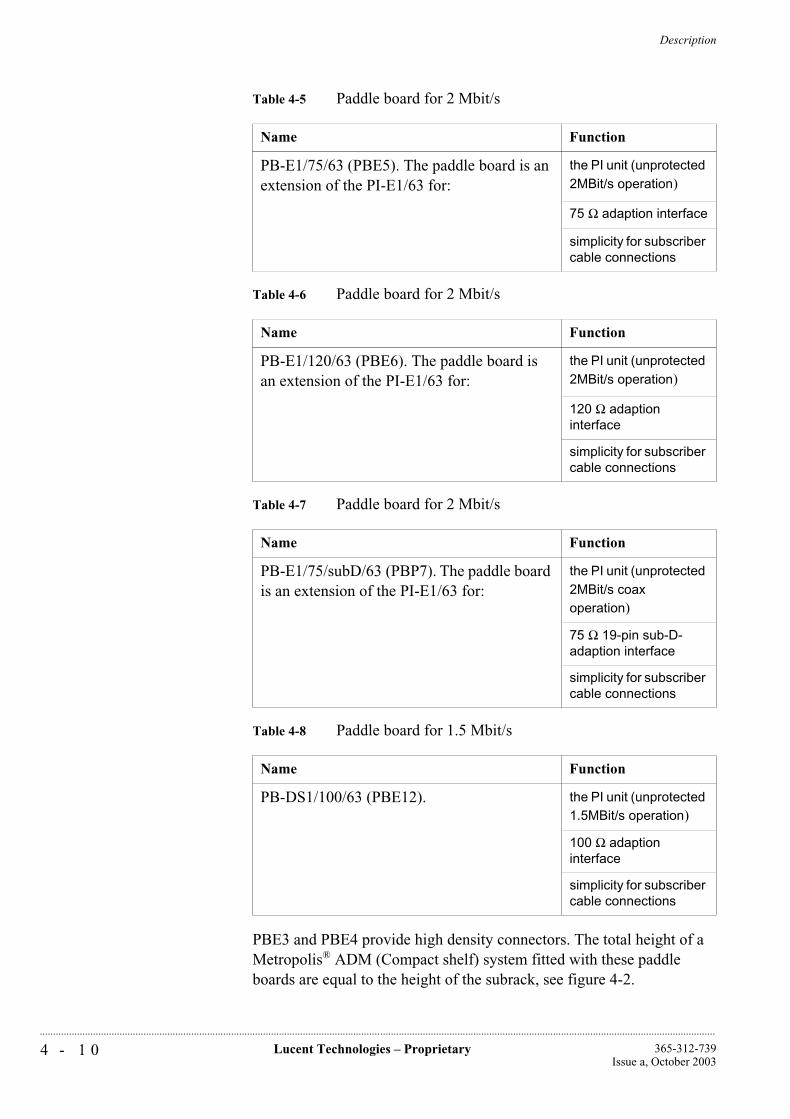
Description
4 - 1 0 Lucent Technologies – Proprietary 365-312-739Issue a, October 2003
..............................................................................................................................................................................................................................................................
Table 4-5 Paddle board for 2 Mbit/s
Table 4-6 Paddle board for 2 Mbit/s
Table 4-7 Paddle board for 2 Mbit/s
Table 4-8 Paddle board for 1.5 Mbit/s
PBE3 and PBE4 provide high density connectors. The total height of a Metropolis® ADM (Compact shelf) system fitted with these paddle boards are equal to the height of the subrack, see figure 4-2.
Name Function
PB-E1/75/63 (PBE5). The paddle board is an extension of the PI-E1/63 for:
the PI unit (unprotected 2MBit/s operation)
75 Ω adaption interface
simplicity for subscriber cable connections
Name Function
PB-E1/120/63 (PBE6). The paddle board is an extension of the PI-E1/63 for:
the PI unit (unprotected 2MBit/s operation)
120 Ω adaption interface
simplicity for subscriber cable connections
Name Function
PB-E1/75/subD/63 (PBP7). The paddle board is an extension of the PI-E1/63 for:
the PI unit (unprotected 2MBit/s coax operation)
75 Ω 19-pin sub-D-adaption interface
simplicity for subscriber cable connections
Name Function
PB-DS1/100/63 (PBE12). the PI unit (unprotected 1.5MBit/s operation)
100 Ω adaption interface
simplicity for subscriber cable connections
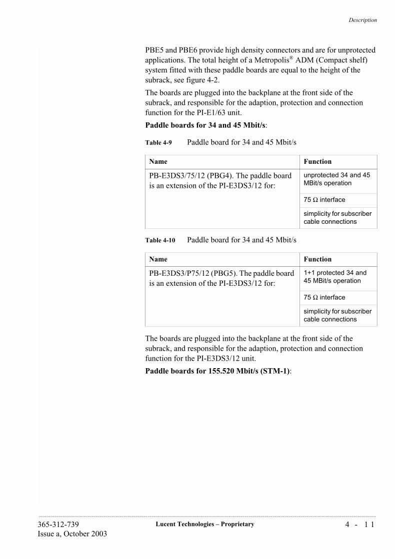
Description
4 - 1 1Lucent Technologies – Proprietary365-312-739Issue a, October 2003
..............................................................................................................................................................................................................................................................
PBE5 and PBE6 provide high density connectors and are for unprotected applications. The total height of a Metropolis® ADM (Compact shelf) system fitted with these paddle boards are equal to the height of the subrack, see figure 4-2.
The boards are plugged into the backplane at the front side of the subrack, and responsible for the adaption, protection and connection function for the PI-E1/63 unit.
Paddle boards for 34 and 45 Mbit/s:
Table 4-9 Paddle board for 34 and 45 Mbit/s
Table 4-10 Paddle board for 34 and 45 Mbit/s
The boards are plugged into the backplane at the front side of the subrack, and responsible for the adaption, protection and connection function for the PI-E3DS3/12 unit.
Paddle boards for 155.520 Mbit/s (STM-1):
Name Function
PB-E3DS3/75/12 (PBG4). The paddle board is an extension of the PI-E3DS3/12 for:
unprotected 34 and 45 MBit/s operation
75 Ω interface
simplicity for subscriber cable connections
Name Function
PB-E3DS3/P75/12 (PBG5). The paddle board is an extension of the PI-E3DS3/12 for:
1+1 protected 34 and 45 MBit/s operation
75 Ω interface
simplicity for subscriber cable connections

Description
4 - 1 2 Lucent Technologies – Proprietary 365-312-739Issue a, October 2003
..............................................................................................................................................................................................................................................................
Table 4-11 Paddle board for 155.520 Mbit/s (STM-1)
The boards are plugged into the backplane at the front side of the subrack, and responsible for the adaption, protection and connection function for the SI-1/4 unit.
Paddle board for LAN 100/8:
Table 4-12 Paddle board for LAN 100/8
NOTE For more details on equipment protection, see Chapter 8, System Planning and Engineering.
Name Function
PB-1/P75/4 (PBG3). The paddle board is an extension of the SI-1/4 for:
protected 1+1 155.520 MBit/s operation
75 Ω interface
simplicity for subscriber cable connections
Name Function
PB-LAN/100/8 (PBG1) paddle board provides connectors for 8 unprotected Ethernet interfaces at 10 Mbit/s or 100 Mbit/s.
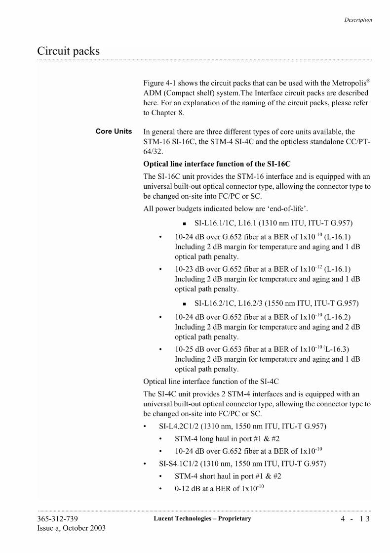
Description
4 - 1 3Lucent Technologies – Proprietary365-312-739Issue a, October 2003
..............................................................................................................................................................................................................................................................
...............................................................................................................................................................................................................................................................Circuit packs
Figure 4-1 shows the circuit packs that can be used with the Metropolis® ADM (Compact shelf) system.The Interface circuit packs are described here. For an explanation of the naming of the circuit packs, please refer to Chapter 8.
Core Units In general there are three different types of core units available, the STM-16 SI-16C, the STM-4 SI-4C and the opticless standalone CC/PT-64/32.
Optical line interface function of the SI-16C
The SI-16C unit provides the STM-16 interface and is equipped with an universal built-out optical connector type, allowing the connector type to be changed on-site into FC/PC or SC.
All power budgets indicated below are ‘end-of-life’.
SI-L16.1/1C, L16.1 (1310 nm ITU, ITU-T G.957)
• 10-24 dB over G.652 fiber at a BER of 1x10⁻¹⁰ (L-16.1)Including 2 dB margin for temperature and aging and 1 dB optical path penalty.
• 10-23 dB over G.652 fiber at a BER of 1x10-12 (L-16.1)Including 2 dB margin for temperature and aging and 1 dB optical path penalty.
SI-L16.2/1C, L16.2/3 (1550 nm ITU, ITU-T G.957)
• 10-24 dB over G.652 fiber at a BER of 1x10⁻¹⁰ (L-16.2)Including 2 dB margin for temperature and aging and 2 dB optical path penalty.
• 10-25 dB over G.653 fiber at a BER of 1x10⁻¹⁰ (L-16.3)Including 2 dB margin for temperature and aging and 1 dB optical path penalty.
Optical line interface function of the SI-4C
The SI-4C unit provides 2 STM-4 interfaces and is equipped with an universal built-out optical connector type, allowing the connector type to be changed on-site into FC/PC or SC.
• SI-L4.2C1/2 (1310 nm, 1550 nm ITU, ITU-T G.957)
• STM-4 long haul in port #1 & #2
• 10-24 dB over G.652 fiber at a BER of 1x10⁻¹⁰
• SI-S4.1C1/2 (1310 nm, 1550 nm ITU, ITU-T G.957)
• STM-4 short haul in port #1 & #2
• 0-12 dB at a BER of 1x10⁻¹⁰
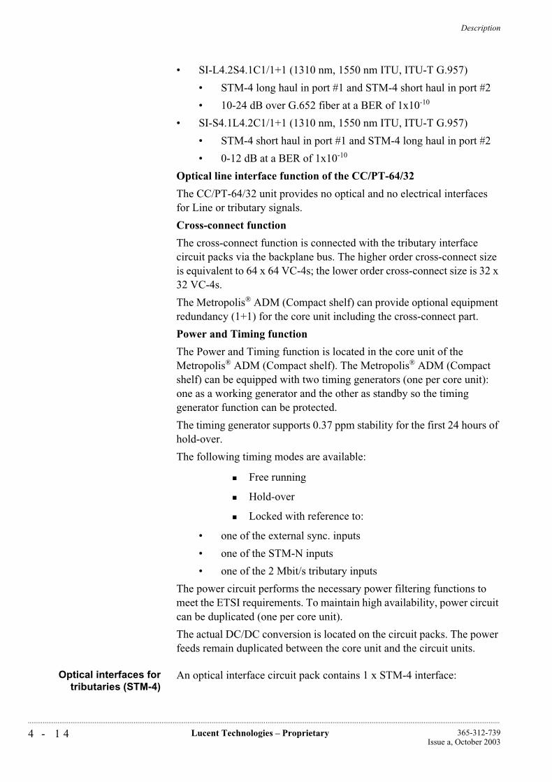
Description
4 - 1 4 Lucent Technologies – Proprietary 365-312-739Issue a, October 2003
..............................................................................................................................................................................................................................................................
• SI-L4.2S4.1C1/1+1 (1310 nm, 1550 nm ITU, ITU-T G.957)
• STM-4 long haul in port #1 and STM-4 short haul in port #2
• 10-24 dB over G.652 fiber at a BER of 1x10⁻¹⁰
• SI-S4.1L4.2C1/1+1 (1310 nm, 1550 nm ITU, ITU-T G.957)
• STM-4 short haul in port #1 and STM-4 long haul in port #2
• 0-12 dB at a BER of 1x10⁻¹⁰
Optical line interface function of the CC/PT-64/32
The CC/PT-64/32 unit provides no optical and no electrical interfaces for Line or tributary signals.
Cross-connect function
The cross-connect function is connected with the tributary interface circuit packs via the backplane bus. The higher order cross-connect size is equivalent to 64 x 64 VC-4s; the lower order cross-connect size is 32 x 32 VC-4s.
The Metropolis® ADM (Compact shelf) can provide optional equipment redundancy (1+1) for the core unit including the cross-connect part.
Power and Timing function
The Power and Timing function is located in the core unit of the Metropolis® ADM (Compact shelf). The Metropolis® ADM (Compact shelf) can be equipped with two timing generators (one per core unit): one as a working generator and the other as standby so the timing generator function can be protected.
The timing generator supports 0.37 ppm stability for the first 24 hours of hold-over.
The following timing modes are available:
Free running
Hold-over
Locked with reference to:
• one of the external sync. inputs
• one of the STM-N inputs
• one of the 2 Mbit/s tributary inputs
The power circuit performs the necessary power filtering functions to meet the ETSI requirements. To maintain high availability, power circuit can be duplicated (one per core unit).
The actual DC/DC conversion is located on the circuit packs. The power feeds remain duplicated between the core unit and the circuit units.
Optical interfaces fortributaries (STM-4)
An optical interface circuit pack contains 1 x STM-4 interface:
Description
4 - 1 5Lucent Technologies – Proprietary365-312-739Issue a, October 2003
..............................................................................................................................................................................................................................................................
S 4.1 (1310 nm, ITU-T G.957), 0-12 dB at a BER of 1x10⁻¹⁰
L 4.2 (1550 nm, ITU-T G.957), 0-24 dB at a BER of 1x10⁻¹⁰
Optical interfaces fortributaries (1000BASE-X)
The Metropolis® ADM (Compact shelf) can also be equipped with 1000BASE-X tributary units. The circuit pack provides two interfaces for which the following optics are available:
— 1000BASE- SX (850 nm short haul, multi-mode) or
— 1000BASE-LX (1310 nm long haul, multi-mode or single-mode)
The 1000BASE-X tributary card is equipped with optics and can have LC connectors.
Optical interfaces fortributaries (STM-1)
An optical interface circuit pack contains 4 x STM-1 interfaces:
S 1.1 (1310 nm, ITU-T G.957), 0-12 dB at a BER of 1x10⁻¹⁰
L 1.2 (1550 nm, ITU-T G.957), 0-28 dB at a BER of 1x10⁻¹⁰
Electrical tributaries circuitpacks
The electrical tributaries circuit packs contain the low-speed interfaces. The interface circuit packs provide the plesiochronous interface circuits or Ethernet LAN interfaces and alignment into TUs.
The following Electrical Interface circuit packs can be provided:
PI-E1/63: 63 x 2 Mbit/s interfaces per circuit pack
PI-DS1/63: 63 x 1.5 Mbit/s interfaces per circuit pack
PI-E3DS3/12: 12 x E3/DS3 switchable interfaces per circuit pack
SI-1/4: 4 x 155.52 Mbit/s interfaces per circuit pack
IP-LAN/8: 8 x 10/100 Mbit/s Base-T interfaces per circuit pack.
Ethernet LAN tributaryboard, IP-LAN/8, (LKA4)
On the Metropolis® ADM (Compact shelf) an Ethernet LAN tributary board (a.k.a. IP-LAN/8) is available providing eight 10/100Base-T Ethernet interfaces. This tributary board is based on the WaveStar® TransLan® Card. When equipped with a WaveStar® TransLan® Card, Lucent Technologies SDH multiplexers can offer besides TDM services like DS1, E1, E3/DS3, E4, STM-1, STM-4 and STM-16 interfaces also 10/100BASE-T Ethernet interfaces. Below a description is given of the Ethernet LAN tributary board functionality supported by the Metropolis® ADM (Compact shelf).
An Ethernet LAN tributary board, based on the WaveStar® TransLan® Card, is also available for the WaveStar® AM 1 Plus and Metropolis®
Description
4 - 1 6 Lucent Technologies – Proprietary 365-312-739Issue a, October 2003
..............................................................................................................................................................................................................................................................
ADM. Please refer to the applicable Application and Planning Guide (APG).
Speed, Cable, Connector
The LAN interfaces that are supported are 10BASE-T and 100BASE-TX. The numbers “10” and “100” indicate the bit-rate of the LAN, 10 Mbit/s and 100 Mbit/s respectively. The “T” or “TX” indicates the wiring and connector type: Twisted pair wiring with RJ-45 connectors.
The actual LAN speed does not need to be configured, since the Ethernet interfaces support the auto-negotiation protocol, which enables them to select automatically the proper LAN speed.
The Auto-negotiation function on the Ethernet LAN tributary board is configurable. This feature allows the auto-negotiation function to be manually overridden from WaveStar® ITM-SC or the ITM-CIT. If this auto-negotiation function is disabled, it is possible to select a specific operational mode (10 or 100BASE-T, Half/Full-Duplex).
CSMA/CD principles
The Ethernet type that is supported by the Ethernet LAN tributary board is according to IEEE 802.3 Ethernet, which means that the access control to the LAN is according to the CSMA/CD principles: Carrier Sense Multiple Access with Collision Detection. “Multiple Access” means that all hosts on the LAN may transmit packets whenever they need to, provided nobody else is transmitting at the same time: “Carrier Sense”. In case there is simultaneous transmission of two or more hosts, the “Collision Detect” part of the protocol prescribes how this situation needs to be detected and resolved. The larger the size of a LAN, the higher the probability of collisions, due to the finite propagation times of the frames over the LAN. For this reason, there are rules about minimum frame lengths and maximum LAN sizes. LAN’s can only be made larger by splitting them in multiple “collision domains”. Within each collision domain, the normal CSMA/CD rules apply.
Traffic between collision domains needs to be transported via a special device known as a bridge. The bridge can store frames from one collision domain and forward it in another collision domain once the LAN is free. A Metropolis® ADM (Compact shelf) equipped with Ethernet LAN tributary boards contain this bridge functionality, which allows to have virtually unlimited distances between the LAN's that need to be interconnected.
To end-users, the “TransLan® Network” (a network build with WaveStar® AM 1 Plus, Metropolis® ADM (Compact shelf) and
Description
4 - 1 7Lucent Technologies – Proprietary365-312-739Issue a, October 2003
..............................................................................................................................................................................................................................................................
Metropolis® ADM equipped with Ethernet LAN tributary boards), appears as a single bridge interconnecting their CPE LAN’s. Thus, end-users do not have to consider the “TransLan® Network” in the design rules (e.g., number of repeaters, distance, collision domain size) of their end-to-end Ethernet network. Collision domains interconnected via “TransLan® Network” are always fully separated.
This is in contrast to the situation where the Metropolis® ADM (Compact shelf) is used as a repeater. A repeater just forwards all frames it receives, without considering the destination MAC address. A repeater does not separate collision domains so the two parts on each side of the repeater should be considered as one Ethernet network.
The implementation of the Ethernet LAN tributary board supports star topologies. The maximum LAN segment of CPE LAN’s connected to the Ethernet LAN tributary board should be compliant to the Ethernet LAN design rules defined in IEEE802.3. As a reference, the maximum distance from an end device (e.g., PC, host) to an Ethernet LAN tributary board should be less than 100 meters.
Ethernet Communication Mode, Speed Negotiation
Data devices connected through a single collision domain of a Fast Ethernet LAN usually communicate in half-duplex mode, a communication method in which a device may either send or receive data at a given instance, but not both.
The newer design of Ethernet switches and hubs today supports both half-duplex and full-duplex mode of communication. Full-duplex mode is a communication method that allows a device connected to the switch or hub to simultaneously send and receive data. To support communication in full-duplex mode, it requires the use of full-duplex media, the cable/wire that provides independent transmit and receive data paths. Note: an Ethernet LAN with full-duplex media does not mean it operates in full-duplex mode.
Before sending and receiving data between two devices connected through an Ethernet LAN, they must both agree to the communication speed (e.g., 10 Mbit/s or 100 Mbit/s), communication mode (half-duplex or full-duplex) and support of flow control capability. The auto-negotiation protocol defined in the Ethernet standard specifies a process to reach such agreement between the devices during the device initialization phase. The process uses special signals to carry the auto-negotiation information between the devices. The Metropolis® ADM (Compact shelf) supports the auto-negotiation protocol and by default, the auto-negotiation function is always on.
In some field cases, it is known that auto-negotiation can fail. In order to allow interworking with equipment not supporting this function, the Metropolis® ADM (Compact shelf) supports an option to override the

Description
4 - 1 8 Lucent Technologies – Proprietary 365-312-739Issue a, October 2003
..............................................................................................................................................................................................................................................................
auto-negotiation. The user has the possibility to disable the auto-negotiation and to force the port speed (10 or 100 Mbit/s) and the half or full-duplex mode.
WAN Bandwidth
To facilitate the flexibility of mapping mixed higher layer traffic into SDH/SONET circuits, and to offer better granularity, ITU G.707 and G.783 (2000 edition) have recently standardized virtual concatenation, a byte-level inverse-multiplexing technique. The virtual concatenation allows the mapping of different types of traffic (e.g., Ethernet, TDM) to individual SDH channels (VCs) that are associated in a concatenated group. The key difference between contiguous concatenation and virtual concatenation is the transport between the path termination. Contiguous concatenation maintains the contiguous bandwidth through out the whole transport, while virtual concatenation breaks the contiguous bandwidth into individual VCs, transports the individual VCs and recombines these VCs to a contiguous bandwidth at the end point of the transmission. Virtual concatenation requires concatenation functionality only at the path termination equipment, while contiguous concatenation requires concatenation functionality at each network element. Thus virtual concatenation is perfectly suited for interworking with legacy nodes in a multi-vendor SDH environment, where traffic can be transparently transported over the legacy nodes not supporting the feature.
WAN bandwidth is supported and defined based on the amount of VCs being allocated (provisioned and configured) for it. The Ethernet LAN tributary board supports WAN bandwidth of mixed VC types. The only limitation is fixed by the maximum capacity between the Ethernet LAN tributary board and the backplane of the Metropolis® ADM (Compact shelf), i.e. two VC-4.
Ethernet WAN Port Capacity Configuration Rules
The encapsulated Ethernet frames are mapped in VC-12 (2 Mbit/s), VC-12-2v (4 Mbit/s), VC12-3v (6 Mbit/s), VC12-4v (8 Mbit/s), VC12-5v (10 Mbit/s), VC3 (50 Mbit/s) or VC3-2v (100 Mbit/s). A user can provision the actual per WAN port bandwidth. Since the backplane capacity is limited, the total combined bandwidth of all WAN ports together must follow the WAN capacity configuration rules defined in table 4-12.
Notice that only the WAN port bandwidth dictates the effective end-to-end Ethernet communication throughput, not the LAN ports.
Description
4 - 1 9Lucent Technologies – Proprietary365-312-739Issue a, October 2003
..............................................................................................................................................................................................................................................................
One Ethernet LAN tributary board supports 8 ports divided over 2 groups. The first WAN port group (Port 1 to 4) supports the possible combination of Ethernet WAN port (total of 4) capacity configurations defined in table 4-12.
The second WAN port group (port 5 to 8) of the Metropolis® ADM (Compact shelf) supports the same capacity configurations as defined for the first WAN port group (port 1 to 4).
The Ethernet LAN tributary board equipped Metropolis® ADM (Compact shelf) system keeps track of the available capacity according to the rules defined in the WAN port configuration table above. If an attempt to configure a new WAN port capacity violates the rules, not only the system does not grant the new configuration but also an alarm (message) is triggered and displayed.
TransLan® Operation Modes
The physical L2 switch that is present on an Ethernet LAN tributary board can be split into several logical or virtual switches. A Virtual Switch is a set of LAN/WAN ports on a Ethernet LAN tributary board that are used by different VLANs which can share the common WAN bandwidth. Each of the virtual switches can operate in a specific Virtual Switch mode depending on the VLAN tagging scheme, and each Virtual Switch mode allows specific LAN-WAN port associations as explained in the following paragraphs.
First the VLAN tagging mode has to be specified on LAN unit level, this can be either IEEE 802.1Q VLAN tagging or VPN-tagging. In VPN tagging mode, end-user VLAN tags that optionally may appear in the end user traffic are ignored in the forwarding process. These VLAN tags are carried transparently through the “TransLan® Network”. In VLAN-tagging mode, the VLAN tags are also carried transparently, but the VLAN ID in the VLAN tags is used in the forwarding decision. Therefore customers' VLAN IDs may not overlap on a physical Ethernet switch, the VLAN IDs must be unique per physical switchannel
Table 4-13 WAN Port Capacity Configuration Rule
WAN Capacity Configuration Case
Capacity of WAN Port 1
Capacity of WAN Port 2
Capacity of WAN Port 3
Capacity of WAN Port 4 Note
1 VC-3-2v VC-12-xv VC-12-x VC-12-xv x = 0, 1,..,5
2 VC-3 VC-3 VC-12-x VC-12-xv x = 0, 1,..,5
3 VC-3 VC-12-xv VC-12-xv VC-12-xv x = 0, 1,..,5
4 VC-12-xv VC-3 VC-12-xv VC-12-xv x = 0, 1,..,5
5 VC-12-xv VC-12-xv VC-12-xv VC-12-xv x = 0, 1,..,5
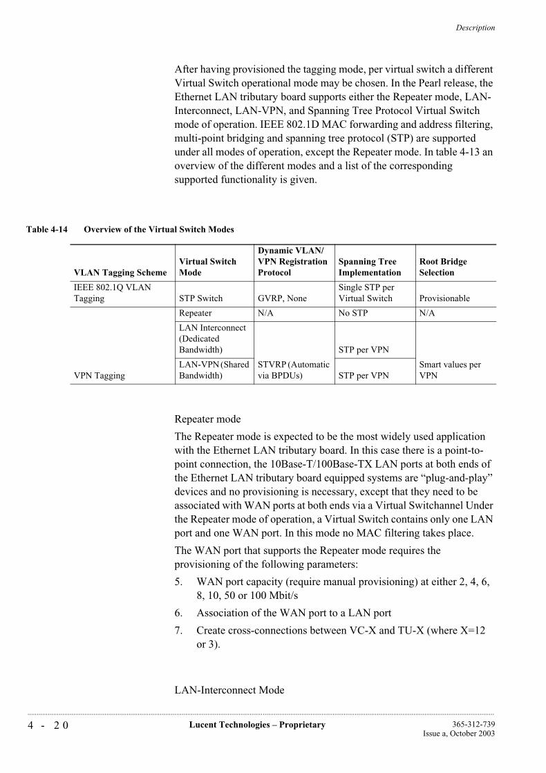
Description
4 - 2 0 Lucent Technologies – Proprietary 365-312-739Issue a, October 2003
..............................................................................................................................................................................................................................................................
After having provisioned the tagging mode, per virtual switch a different Virtual Switch operational mode may be chosen. In the Pearl release, the Ethernet LAN tributary board supports either the Repeater mode, LAN-Interconnect, LAN-VPN, and Spanning Tree Protocol Virtual Switch mode of operation. IEEE 802.1D MAC forwarding and address filtering, multi-point bridging and spanning tree protocol (STP) are supported under all modes of operation, except the Repeater mode. In table 4-13 an overview of the different modes and a list of the corresponding supported functionality is given.
0
Repeater mode
The Repeater mode is expected to be the most widely used application with the Ethernet LAN tributary board. In this case there is a point-to-point connection, the 10Base-T/100Base-TX LAN ports at both ends of the Ethernet LAN tributary board equipped systems are “plug-and-play” devices and no provisioning is necessary, except that they need to be associated with WAN ports at both ends via a Virtual Switchannel Under the Repeater mode of operation, a Virtual Switch contains only one LAN port and one WAN port. In this mode no MAC filtering takes place.
The WAN port that supports the Repeater mode requires the provisioning of the following parameters:
5. WAN port capacity (require manual provisioning) at either 2, 4, 6, 8, 10, 50 or 100 Mbit/s
6. Association of the WAN port to a LAN port
7. Create cross-connections between VC-X and TU-X (where X=12 or 3).
LAN-Interconnect Mode
Table 4-14 Overview of the Virtual Switch Modes
VLAN Tagging SchemeVirtual Switch Mode
Dynamic VLAN/VPN Registration Protocol
Spanning Tree Implementation
Root Bridge Selection
IEEE 802.1Q VLAN Tagging STP Switch GVRP, None
Single STP per Virtual Switch Provisionable
VPN Tagging
Repeater N/A No STP N/A
LAN Interconnect (Dedicated Bandwidth)
STVRP (Automatic via BPDUs)
STP per VPN
Smart values per VPN
LAN-VPN (Shared Bandwidth) STP per VPN
Description
4 - 2 1Lucent Technologies – Proprietary365-312-739Issue a, October 2003
..............................................................................................................................................................................................................................................................
The LAN-interconnect mode of operation offers dedicated WAN bandwidth to a single end-user. Under the LAN-interconnect mode of operation, a Virtual Switch must only contain LAN ports with the same CID (Customer ID) to ensure the entire WAN port bandwidth allocated for the group is dedicated to a single end-user. Any combination of LAN- and WAN-ports is allowed (but with a minimum of two ports to be meaningful).
LAN-VPN Mode
Under the LAN-VPN mode, a number of LAN- and WAN ports are grouped together to form one virtual switchannel The Virtual Switch contains LAN ports of multiple end-users sharing the same WAN port (s) bandwidth. To safeguard each individual end-user's data flow and to identify an end-user's VPN from the shared WAN, the Ethernet LAN board equipped system assigns a CID to each LAN port within a Virtual Switchannel The CID of each end-user (or LAN port) must be unique within a shared WAN port to create a fully independent VPN. The VPN provisioning on the WAN ports on the access and intermediate nodes is done automatically by the proprietary protocol STVRP (Spanning Tree with VPN Registration Protocol) which runs without operator intervention.
The LAN-VPN mode of operation controls the shared bandwidth by making use of the following features:
SDH WAN bandwidth sharing:
Allows multiple end-users to share the same SDH WAN bandwidth with each end-user being allocated a sub-VC12-Xv (X= 1, 2, 3, 4, 5) or sub-VC3 rate of bandwidth. The combined end-user bandwidth is then mapped to the SDH time-slots and transported in the SDH network as a single data load. The minimum sub-VC12 rate that can be configured per end-user at a LAN port is 150 kbit/s.
Strict policing/Oversubscription mode: See section Quality of Service.
The LAN-interconnect mode of operation is a special case of LAN-VPN operation where a Virtual Switch contains LAN and WAN ports of a single end-user only. Note the Ethernet LAN tributary board can support both LAN-interconnect and LAN-VPN mode of operations simultaneously as long as a Virtual Switch under each operation mode does not include the same WAN port (s) used by the other operation.
LAN-VPN with 802.1p QoS Mode
This mode is identical to the “normal” LAN-VPN mode, with the addition of the enhanced Quality of Service features described in the
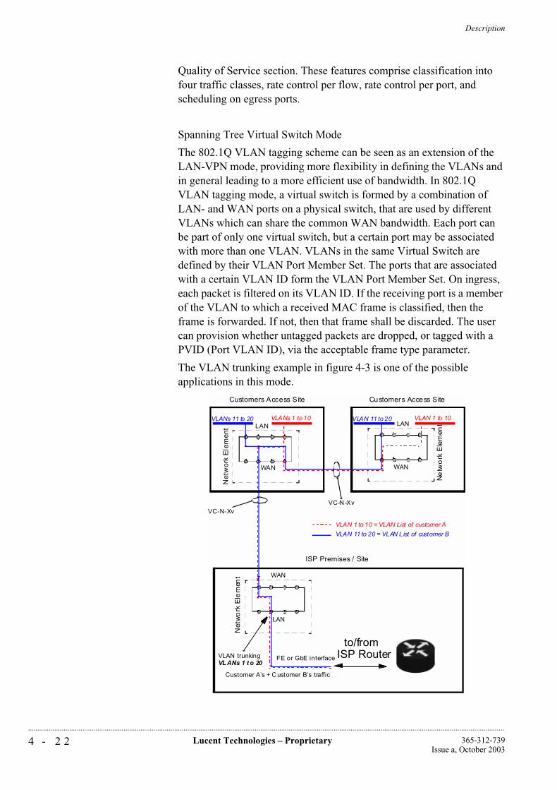
Description
4 - 2 2 Lucent Technologies – Proprietary 365-312-739Issue a, October 2003
..............................................................................................................................................................................................................................................................
Quality of Service section. These features comprise classification into four traffic classes, rate control per flow, rate control per port, and scheduling on egress ports.
Spanning Tree Virtual Switch Mode
The 802.1Q VLAN tagging scheme can be seen as an extension of the LAN-VPN mode, providing more flexibility in defining the VLANs and in general leading to a more efficient use of bandwidth. In 802.1Q VLAN tagging mode, a virtual switch is formed by a combination of LAN- and WAN ports on a physical switch, that are used by different VLANs which can share the common WAN bandwidth. Each port can be part of only one virtual switch, but a certain port may be associated with more than one VLAN. VLANs in the same Virtual Switch are defined by their VLAN Port Member Set. The ports that are associated with a certain VLAN ID form the VLAN Port Member Set. On ingress, each packet is filtered on its VLAN ID. If the receiving port is a member of the VLAN to which a received MAC frame is classified, then the frame is forwarded. If not, then that frame shall be discarded. The user can provision whether untagged packets are dropped, or tagged with a PVID (Port VLAN ID), via the acceptable frame type parameter.
The VLAN trunking example in figure 4-3 is one of the possible applications in this mode.
Net
wor
k E
lem
ent
VLANs 11 to 20
Net
wo
rk E
lem
ent
VLANs 1 to 10
Ne
two
rk E
lem
ent
VC-N-Xv
VLAN 1 to 10VLAN 11 to 20
VC-N-Xv
LAN
LANLAN
WAN
WAN WAN
to/fromISP RouterVLAN trunking
Customers Access Site Customers Access Site
ISP Premises / Site
FE or GbE interface
VLAN 11 to 20 = VLAN L ist of customer B
VLAN 1 to 10 = VLAN List of customer A
Customer A’s + C ustomer B’s traffic
VLANs 1 t o 20

Description
4 - 2 3Lucent Technologies – Proprietary365-312-739Issue a, October 2003
..............................................................................................................................................................................................................................................................
Figure 4-3 VLAN Trunking Application Example
VLAN IDs assigned to LAN Ports should not overlap in case the operator wants to ensure Layer-2 security between those LAN Ports (In many applications, LAN Ports are likely to be dedicated to one customer). It is the responsibility of the operator to define appropriately non-overlapping VLAN IDs on all the created virtual switches. Also the provisioned PVID, with which untagged incoming frames are tagged, should not overlap with any VLAN ID on the virtual switch of which the customers' port is part (again, this is the responsibility of the operator).
Manual provisioning of intermediate nodes can be cumbersome and difficult. Therefore it is recommended to use the auto-provisioning mode for VLAN ID's on the intermediate nodes. A protocol named GVRP (Generic VLAN Registration Protocol provides this functionality. GVRP is an application of the Generic Attribute Registration Protocol (GARP) application, which runs on top of the active spanning tree topology.
IEEE 802.1Q defines two kinds of VLAN registration entries in the Bridge Filtering Database: static and dynamic entries. The static entries can only be entered by the user, the dynamic entries are added automatically by the GVRP protocol. In the Ethernet LAN tributary board implementation, static entries need to be provisioned only on access node's LAN ports. GVRP takes care of configuring dynamic entries on the WAN ports of intermediate and access nodes.
A spanning tree per virtual switch is implemented. If the user wants the traffic to be protected by the spanning tree protocol and he uses the manual provisioning mode, he must make sure that the WAN ports in the alternative path also have the corresponding VLAN ID assigned. E.g. in a ring topology, all NE's in the ring must be provisioned with this VLAN ID. In automatic mode, the GVRP protocol takes care of the dynamic VLAN provisioning.
The user has the possibility to flush dynamic VLANs, thus remove dynamic VLANs that are no longer used.
For the 802.1Q VLAN tagging mode, the Oversubscription Mode is not supported.
Only independent VLAN learning is supported on the Ethernet LAN tributary board. This means, if a given MAC address is learned in a VLAN, the learned information is used in forwarding decisions taken for that address only relative to that VLAN.
Virtual Switch modes Interoperability
The releases that came after Ruby are all downward compatible, they support the same modes of operation that are present in the Ruby release. Virtual Switches that are configured in the same operational mode can interwork. Virtual Switches not configured in the same operational mode
Description
4 - 2 4 Lucent Technologies – Proprietary 365-312-739Issue a, October 2003
..............................................................................................................................................................................................................................................................
do not interwork in all cases. If a Virtual Switch is configured in the “Repeater” mode or the “STP Switch” mode, it can only interwork with Virtual Switches that are configured in the same mode. Interworking between a remote LAN-interconnect virtual switch and a LAN-VPN virtual switch is not prohibited, because the LAN-interconnect mode can be seen as a special case of the LAN-VPN mode.
Spanning Tree Protocol
Ethernet MAC service does not permit duplication of Ethernet frames between any source and destination end station pair. The potential for frame duplication in a bridged network (e.g., LAN) happens when multiple paths between the source and destination end station pair. When multiple paths exist between any source-destination pair, a loop occurs in the bridged network.
IEEE 802.1D defines Spanning Tree Protocol (STP) to prevent a bridged network (e.g., LAN) from creating network loops. By using the STP, bridges communicate to each other by exchanging Bridge Protocol Data Units (BPDUs) configuring a simple connected active topology. Frames are forwarded through some of the bridged ports (with forwarding state) but not to the ports/segments, which are held in a blocking state. Ports that are in a blocking state do not forward frames in either direction but may be put into a forwarding state should the active topology and path fail. With STP, the algorithm ensures that only one active path is used to forward frames from any source port to any destination port. The STP algorithm uses bridge priority, port priority and path cost to compare and select an active path.
The user can track back the path from a NE to the root by successively retrieving the Root Port for each NE in the path. The user can influence the STP choice of root and topology by modifying the bridge/port priority of individual bridges/ports and the path cost of individual links. This influence is indirectly however, the Spanning Tree Protocol itself evaluates all these parameters to determine the root and calculate a topology.
The STP support in the “TransLan® Network” is invisible to end-users because STP is only applied to WAN ports to resolve loops in the WAN network. The end-user's BPDUs are transported transparently through the “TransLan® Network”. Therefore, to end-users connected to the “TransLan® Network” through LAN ports, the “TransLan® Network” appears like a single bridge that does not support STP. See figure 4-4.
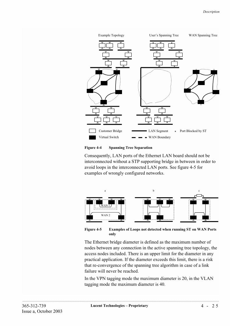
Description
4 - 2 5Lucent Technologies – Proprietary365-312-739Issue a, October 2003
..............................................................................................................................................................................................................................................................
Figure 4-4 Spanning Tree Separation
Consequently, LAN ports of the Ethernet LAN board should not be interconnected without a STP supporting bridge in between in order to avoid loops in the interconnected LAN ports. See figure 4-5 for examples of wrongly configured networks.
Figure 4-5 Examples of Loops not detected when running ST on WAN Ports only
The Ethernet bridge diameter is defined as the maximum number of nodes between any connection in the active spanning tree topology, the access nodes included. There is an upper limit for the diameter in any practical application. If the diameter exceeds this limit, there is a risk that re-convergence of the spanning tree algorithm in case of a link failure will never be reached.
In the VPN tagging mode the maximum diameter is 20, in the VLAN tagging mode the maximum diameter is 40.
Example Topology User’s Spanning Tree WAN Spanning Tree
Customer Bridge
Virtual Switch
LAN Segment
WAN Boundary
Port Blocked by ST
a b c
WAN 2
WAN 1

Description
4 - 2 6 Lucent Technologies – Proprietary 365-312-739Issue a, October 2003
..............................................................................................................................................................................................................................................................
The Ethernet LAN tributary board supports a single STP per Virtual Switch under LAN-Interconnect mode and a single STP per VPN under the LAN-VPN mode. In the STP Virtual Switch mode, the Ethernet LAN tributary board supports a single STP per Virtual Switchannel When operating in the Repeater mode, the Ethernet virtual bridge (an instance of the TransLan® Ethernet bridging function) must not participate in a STP.
In the STP Virtual Switch mode, a number of STP status parameters per Port/Virtual Switch are retrievable/editable. The most important ones are the support of Port State retrieval and the support of Bridge/Port Priority provisioning.
The Port State can have one of the following values:
Disabled - The port is disabled completely.
Blocking - BPDUs and normal frames are discarded.
Listening - BPDUs are processed, but normal frames are discarded. The Filtering Database is not updated.
Learning - BPDUs are processed, but normal frames are discarded Received. BPDUs are used to learn addresses and update the Filtering Database.
Forwarding - BPDUs are processed and normal frames are forwarded.

Description
4 - 2 7Lucent Technologies – Proprietary365-312-739Issue a, October 2003
..............................................................................................................................................................................................................................................................
Path Cost provisioning:
The system sets a default STP path cost for each link which is inverse proportional to the speed (2, 4, 6, 8, 10, 50 and 100 Mbit/s). BPDUs are capable of carrying 32 bits of Path Cost information; however, IEEE Std. 802.1D, 1998 edition and earlier revisions of this standard limited the range of the Path Cost parameter to a 16-bit unsigned integer value. The recommended values in IEEE Std. 802.1t-2001, make use of the full 32 bit range available in BPDUs in order to extend the range of link speeds supported by the protocol. In LAN’s where bridges that use the recommended values defined in the IEEE Std. 802.1D, 1998 edition and bridges that use the recommended values in IEEE Std. 802.1t-2001 are required to inter-operate, either the older Bridges or the new Bridges need to be reconfigured to make Path Cost values compatible. However, this situation is not likely to occur since the first release of STP in IEEE 802.1Q tagging supports the values recommended in IEEE Std. 802.1t-2001.
Bridge Priority provisioning:
Ranges and granularities for Port Priority defined in IEEE Std. 802.1D, 1998 edition have been modified in IEEE Std. 802.1t, 2001 edition: value range should now be expressed in steps of 4096 instead of 1. The step values chosen ensure that the low-order bits that have been re-assigned cannot be modified (Bridge priority 12 low-order bits have become a 12-bit system ID extension for Multiple Spanning Trees). The magnitude of the priority values can be directly compared with those based on previous versions of the standard, which ensures full interoperability. Although the NE and management systems support a granularity of 1, it is advised to provision a Port Priority with the new granularity of 4096 in order to ensure interoperability.
Port Priority provisioning:
Ranges and granularities for Port Priority defined in IEEE Std. 802.1D, 1998 edition have been modified in IEEE Std. 802.1t, 2001 edition: value range should now be expressed in steps of 16 instead of 1. The step values chosen ensure that the low-order bits that have been re-assigned cannot be modified (Port priority 4 low-order bits are now considered to be part of the Port Number). The magnitude of the priority values can be directly compared with those based on previous versions of the standard, which ensures full interoperability. Although the NE and management systems support a granularity of 1, it is advised to provision a Port Priority with the new granularity of 16 in order to ensure interoperability.
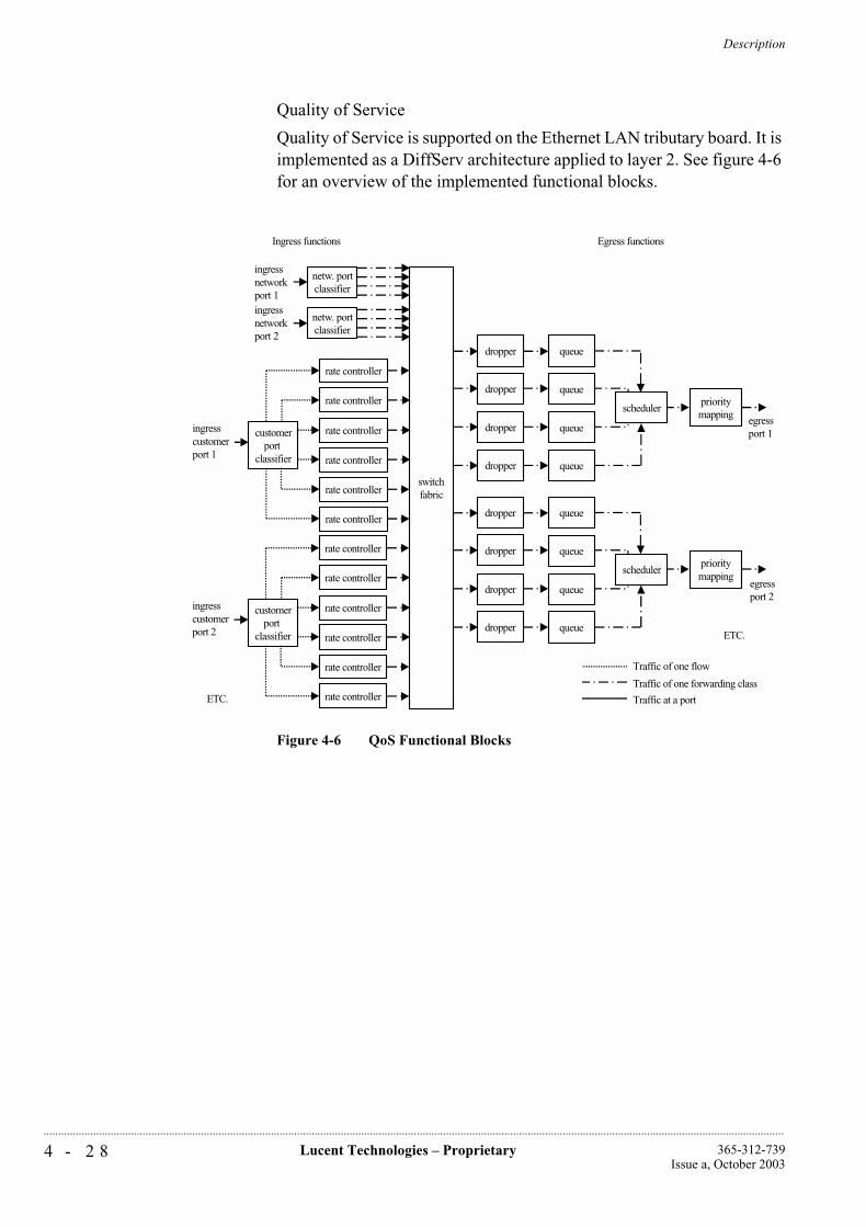
Description
4 - 2 8 Lucent Technologies – Proprietary 365-312-739Issue a, October 2003
..............................................................................................................................................................................................................................................................
Quality of Service
Quality of Service is supported on the Ethernet LAN tributary board. It is implemented as a DiffServ architecture applied to layer 2. See figure 4-6 for an overview of the implemented functional blocks.
Figure 4-6 QoS Functional Blocks
switchfabric
netw. portclassifier
netw. portclassifier
queue
prioritymapping
dropper
dropper
dropper
dropper queue
scheduler
queue
queue
rate controller
rate controller
rate controller
rate controller
rate controller
rate controller
customerport
classifier
ingresscustomerport 1
egressport 1
ingressnetworkport 1ingressnetworkport 2
rate controller
rate controller
rate controller
rate controller
rate controller
rate controller
customerport
classifier
ingresscustomerport 2
queue
prioritymapping
dropper
dropper
dropper
dropper queue
scheduler
queue
queue
ETC.
ETC.
egressport 2
Egress functionsIngress functions
Traffic of one flow
Traffic of one forwarding class
Traffic at a port
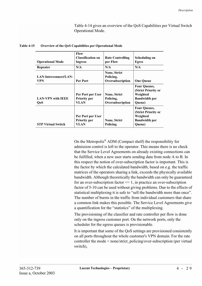
Description
4 - 2 9Lucent Technologies – Proprietary365-312-739Issue a, October 2003
..............................................................................................................................................................................................................................................................
Table 4-14 gives an overview of the QoS Capabilities per Virtual Switch Operational Mode.
On the Metropolis® ADM (Compact shelf) the responsibility for admission control is left to the operator. This means there is no check that the Service Level Agreements on already existing connections can be fulfilled, when a new user starts sending data from node A to B. In this respect the notion of over-subscription factor is important. This is the factor by which the calculated bandwidth, based on e.g. the traffic matrices of the operators sharing a link, exceeds the physically available bandwidth. Although theoretically the bandwidth can only be guaranteed for an over-subscription factor <= 1, in practice an over-subscription factor of 5-10 can be used without giving problems. Due to the effects of statistical multiplexing it is safe to “sell the bandwidth more than once”. The number of bursts in the traffic from individual customers that share a common link makes this possible. The Service Level Agreements give a quantification for the “statistics” of the multiplexing.
The provisioning of the classifier and rate controller per flow is done only on the ingress customer port. On the network ports, only the scheduler for the egress queues is provisionable.
It is important that some of the QoS settings are provisioned consistently on all ports throughout the whole customer's VPN domain. For the rate controller the mode = none/strict_policing/over-subscription (per virtual switch),
Table 4-15 Overview of the QoS Capabilities per Operational Mode
Operational Mode
Flow Classification on Ingress
Rate Controlling per Flow
Scheduling on Egres
Repeater N/A N/A N/A
LAN-Interconnect/LAN-VPN Per Port
None, Strict Policing, Oversubscription One Queue
LAN-VPN with IEEE QoS
Per Port per User Priority per VLAN
None, Strict Policing, Oversubscription
Four Queues, (Strict Priority or Weighted Bandwidth per Queue)
STP Virtual Switch
Per Port per User Priority per VLAN
None, Strict Policing
Four Queues, (Strict Priority or Weighted Bandwidth per Queue)
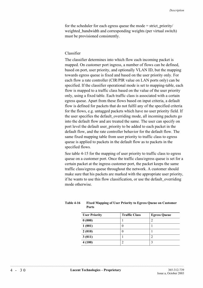
Description
4 - 3 0 Lucent Technologies – Proprietary 365-312-739Issue a, October 2003
..............................................................................................................................................................................................................................................................
for the scheduler for each egress queue the mode = strict_priority/weighted_bandwidth and corresponding weights (per virtual switch) must be provisioned consistently.
Classifier
The classifier determines into which flow each incoming packet is mapped. On customer port ingress, a number of flows can be defined, based on port, user priority, and optionally VLAN ID, but the mapping towards egress queue is fixed and based on the user priority only. For each flow a rate controller (CIR/PIR value on LAN ports only) can be specified. If the classifier operational mode is set to mapping-table, each flow is mapped to a traffic class based on the value of the user priority only, using a fixed table. Each traffic class is associated with a certain egress queue. Apart from these flows based on input criteria, a default flow is defined for packets that do not fulfil any of the specified criteria for the flows, e.g. untagged packets which have no user priority field. If the user specifies the default_overriding mode, all incoming packets go into the default flow and are treated the same. The user can specify on port level the default user_priority to be added to each packet in the default flow, and the rate controller behavior for the default flow. The same fixed mapping table from user priority to traffic class to egress queue is applied to packets in the default flow as to packets in the specified flows.
See table 4-15 for the mapping of user priority to traffic class to egress queue on a customer port. Once the traffic class/egress queue is set for a certain packet at the ingress customer port, the packet keeps the same traffic class/egress queue throughout the network. A customer should make sure that his packets are marked with the appropriate user priority, if he wants to use this flow classification, or use the default_overriding mode otherwise.
Table 4-16 Fixed Mapping of User Priority to Egress Queue on Customer Ports
User Priority Traffic Class Egress Queue
0 (000) 1 2
1 (001) 0 1
2 (010) 0 1
3 (011) 1 2
4 (100) 2 3
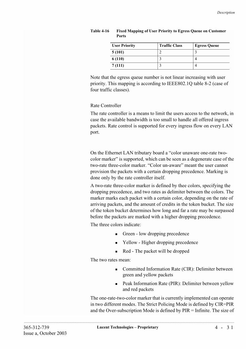
Description
4 - 3 1Lucent Technologies – Proprietary365-312-739Issue a, October 2003
..............................................................................................................................................................................................................................................................
Note that the egress queue number is not linear increasing with user priority. This mapping is according to IEEE802.1Q table 8-2 (case of four traffic classes).
Rate Controller
The rate controller is a means to limit the users access to the network, in case the available bandwidth is too small to handle all offered ingress packets. Rate control is supported for every ingress flow on every LAN port.
On the Ethernet LAN tributary board a “color unaware one-rate two-color marker” is supported, which can be seen as a degenerate case of the two-rate three-color marker. “Color un-aware” meant the user cannot provision the packets with a certain dropping precedence. Marking is done only by the rate controller itself.
A two-rate three-color marker is defined by thee colors, specifying the dropping precedence, and two rates as delimiter between the colors. The marker marks each packet with a certain color, depending on the rate of arriving packets, and the amount of credits in the token bucket. The size of the token bucket determines how long and far a rate may be surpassed before the packets are marked with a higher dropping precedence.
The three colors indicate:
Green - low dropping precedence
Yellow - Higher dropping precedence
Red - The packet will be dropped
The two rates mean:
Committed Information Rate (CIR): Delimiter between green and yellow packets
Peak Information Rate (PIR): Delimiter between yellow and red packets
The one-rate-two-color marker that is currently implemented can operate in two different modes. The Strict Policing Mode is defined by CIR=PIR and the Over-subscription Mode is defined by PIR = Infinite. The size of
5 (101) 2 3
6 (110) 3 4
7 (111) 3 4
Table 4-16 Fixed Mapping of User Priority to Egress Queue on Customer Ports
User Priority Traffic Class Egress Queue
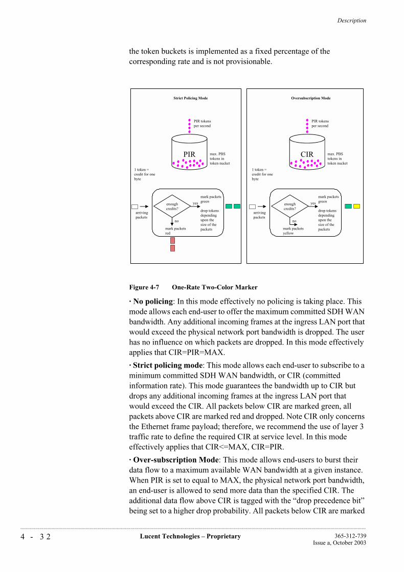
Description
4 - 3 2 Lucent Technologies – Proprietary 365-312-739Issue a, October 2003
..............................................................................................................................................................................................................................................................
the token buckets is implemented as a fixed percentage of the corresponding rate and is not provisionable.
Figure 4-7 One-Rate Two-Color Marker
· No policing: In this mode effectively no policing is taking place. This mode allows each end-user to offer the maximum committed SDH WAN bandwidth. Any additional incoming frames at the ingress LAN port that would exceed the physical network port bandwidth is dropped. The user has no influence on which packets are dropped. In this mode effectively applies that CIR=PIR=MAX.
· Strict policing mode: This mode allows each end-user to subscribe to a minimum committed SDH WAN bandwidth, or CIR (committed information rate). This mode guarantees the bandwidth up to CIR but drops any additional incoming frames at the ingress LAN port that would exceed the CIR. All packets below CIR are marked green, all packets above CIR are marked red and dropped. Note CIR only concerns the Ethernet frame payload; therefore, we recommend the use of layer 3 traffic rate to define the required CIR at service level. In this mode effectively applies that CIR<=MAX, CIR=PIR.
· Over-subscription Mode: This mode allows end-users to burst their data flow to a maximum available WAN bandwidth at a given instance. When PIR is set to equal to MAX, the physical network port bandwidth, an end-user is allowed to send more data than the specified CIR. The additional data flow above CIR is tagged with the “drop precedence bit” being set to a higher drop probability. All packets below CIR are marked
enoughcredits?
yes
no
mark packetsgreen
drop tokensdependingupon thesize of thepacketsmark packets
red
arrivingpackets
PIR
PIR tokensper second
max. PBStokens intoken nucket
1 token = credit for onebyte
Strict Policing Mode
enoughcredits?
yes
no
mark packetsgreen
drop tokensdependingupon thesize of thepacketsmark packets
yellow
arrivingpackets
CIR
PIR tokensper second
max. PBStokens intoken nucket
1 token = credit for onebyte
Oversubscription Mode
Description
4 - 3 3Lucent Technologies – Proprietary365-312-739Issue a, October 2003
..............................................................................................................................................................................................................................................................
green, all packets above CIR are marked yellow. In this mode effectively applies that CIR<=PIR, PIR=MAX.
Dropper
The dropper function decides whether to drop or forward a packet. On the Ethernet LAN tributary board a deterministic dropping from tail when the queue is full is implemented. Packets that are marked red are always dropped. If WAN Ethernet Link congestion occurs, frames are dropped. Yellow packets are always dropped before any of the green packets are dropped. This is the only dependency on queue occupation and packet color that is currently present in the dropper function. No provisioning is needed.
Scheduler
The preceding functional blocks assure that all packets in the four queues can be handled by the scheduler, no further packets need to be dropped. The order in which packets from the four queues are forwarded, is determined by the scheduler.
The scheduler on each of the four egress queues can be in two operational modes, strict priority or weighted bandwidth. Any combination of queues in either of the two modes is allowed. When exactly one queue is in weighted bandwidth mode, it is interpreted as a strict priority queue with the lowest priority. Normally the queue with the lowest number also has the lowest ranking order, but this ranking order of the strict priority queues may be redefined by the user. It is recommended not to change the mode and ranking of the queue with the highest number (=4) however, because this queue is also used by protocol packets like spanning tree BPDU's and GVRP PDUs.
Strict Priority Mode
The packets in strict priority queues are forwarded strictly according to the queue ranking. The queue with the highest ranking is served first. A queue with a certain ranking is only served when the queues with a higher ranking are empty.
Weighted Bandwidth Mode
The weights of the weighted bandwidth queues are summed up; each queue gets a portion relative to its weight divided by this summed weight, the so called normalized weight. The packets in the weighted bandwidth queues are handled in a Round-Robin order according to their normalized weight.
Description
4 - 3 4 Lucent Technologies – Proprietary 365-312-739Issue a, October 2003
..............................................................................................................................................................................................................................................................
Each of the two modes has his well-known advantages and drawbacks. Strict Priority queues are always served before Weighted Bandwidth queues. So with strict priority, starvation of the lower priority queues cannot be excluded. Starvation should be avoided by assuring that upstream policing is configured such that the queue is only allowed to occupy some fraction of the output link's capacity. This can be done by setting the strict policing rate control mode for the flows that map into this queue, and specifying an appropriate value for the CIR. The strict priority scheme can be used for low-latency traffic such as Voice over IP and protocol data such as spanning tree BPDUs or GVRP PDUs.
Weighted Bandwidth queues are useful to assign a guaranteed bandwidth to each of the queues. The bandwidth can of course only be guaranteed if concurrent strict priority queues are appropriately rate-limited. The assigned weight factor represent 256-byte quanta in the weighted Round-Robin algorithm. To reduce the number of bursts between the queue transmissions, the user should strive for minimal weight factors, which are however bigger than the maximum length of a packet. This is achieved by a weight factor of at least six (6*256>1500).
Performance Monitoring
On the VC3/VC12 termination points that are connected to a WAN port, the “normal” performance monitoring can be activated. The same counters that apply for VC3/VC12TPs on any other port also apply to the VC3/VC12 TPs on a WAN port.
Apart from this standard SDH PM, a limited amount of counters that are dedicated to LAN/WAN ports are defined. Activation of these counters can be established by setting the LAN port mode to monitored, selecting a LAN port or WAN port as active PM point, and setting the PM point type to LAN or WAN.
The supported dedicated parameters are:
CbS (total number of bytes sent)
CbR (total number of bytes received)
pDe (packets in error dropped)
Note that CbS and CbR are rather traffic monitoring counters than performance monitoring counters, as they give insight in the traffic load in all places in the network. pDe is a real performance monitoring counter as it gives an indication about the performance of the network. Only unidirectional PM is supported for these parameters. See figure 4-8 for the location of the measurements. Note that because of the difference in units, bytes versus packets, the counters cannot be correlated with each other. Also the counter for dropped packets considers only packets
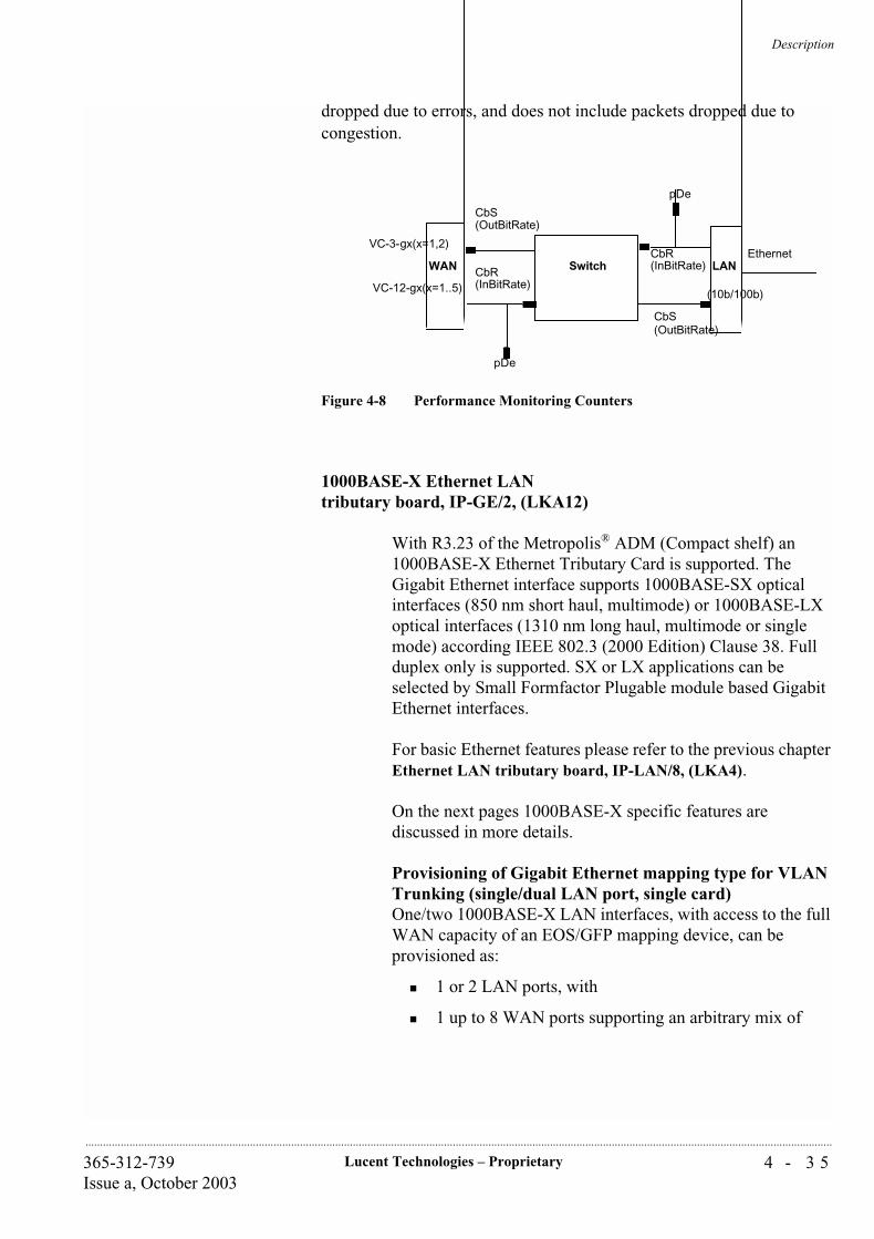
Description
4 - 3 5Lucent Technologies – Proprietary365-312-739Issue a, October 2003
..............................................................................................................................................................................................................................................................
dropped due to errors, and does not include packets dropped due to congestion.
Figure 4-8 Performance Monitoring Counters
1000BASE-X Ethernet LAN tributary board, IP-GE/2, (LKA12) 0
With R3.23 of the Metropolis® ADM (Compact shelf) an 1000BASE-X Ethernet Tributary Card is supported. The Gigabit Ethernet interface supports 1000BASE-SX optical interfaces (850 nm short haul, multimode) or 1000BASE-LX optical interfaces (1310 nm long haul, multimode or single mode) according IEEE 802.3 (2000 Edition) Clause 38. Full duplex only is supported. SX or LX applications can be selected by Small Formfactor Plugable module based Gigabit Ethernet interfaces.
For basic Ethernet features please refer to the previous chapter Ethernet LAN tributary board, IP-LAN/8, (LKA4).
On the next pages 1000BASE-X specific features are discussed in more details.
Provisioning of Gigabit Ethernet mapping type for VLAN Trunking (single/dual LAN port, single card)One/two 1000BASE-X LAN interfaces, with access to the full WAN capacity of an EOS/GFP mapping device, can be provisioned as:
1 or 2 LAN ports, with
1 up to 8 WAN ports supporting an arbitrary mix of
SwitchWAN LAN
(10b/100b)
VC-3-gx(x=1,2)
VC-12-gx(x=1..5)
Ethernet
CbS(OutBitRate)
CbR(InBitRate)
pDe
pDe
CbR(InBitRate)
CbS(OutBitRate)
Description
4 - 3 6 Lucent Technologies – Proprietary 365-312-739Issue a, October 2003
..............................................................................................................................................................................................................................................................
VC-3, VC-3-1v, VC-3-2v (EOS or GFP mapped) and VC-4-1v, VC-4-2v, VC-4-3v, VC-4-4v (GFP mapped) type VC-groups, as long as the TDM slot/backplane capacity of the system is not exceeded
Provisioning of Gigabit Ethernet mapping type for GbE “lite” (single LAN port, single card)One 1000BASE-X LAN interface, with access to the full WAN capacity of an EOS/GFP mapping device, can be provisioned as:
1 LAN port, with
1 or 2 WAN ports containing an arbitrary mix of
VC-4-1v, VC-4-2v, VC-4-3v, VC-4-4v (GFP mapped) VC-groups, as long as the TDM slot/backplane capacity of the system is not exceeded. This is known as GbE “lite” (up to 600 Mb/s), or GbE “ultra-lite” packet ring (300 Mb/s).
Provisioning of Ethernet mapping type for WAN-to-WAN grooming/aggregation (single card)The system that supports a WAN-to-WAN grooming/aggregation function (no LAN ports) with access to the full WAN capacity of an EOS/GFP mapping device, can be provisioned as:
0 LAN ports,
1 up to 8 WAN ports with a grooming/aggregation capability of
VC-3 (EOS mapped) in VC-3-2v (GFP mapped) and/or VC-3, VC-3-Xv in VC-4-Xv type VC-groups, as long as the TDM slot/backplane capacity of the system is not exceeded.
This feature is known as VC-3 to VC-4 “grooming” and EOS to GFP “conversion”.
Mapping of Ethernet MAC frames into VC-4- Xv (GFP encapsulation)Ethernet MAC frames are mapped into/recovered from one, up to 4 VC-4's according to:
1000BASE-X «T1X1.5/2001-024r4 (ITU-T G.7041) protocol «C4-Xc «VC-4-Xv «X*VC-4 (X=1,.., 4). Generic Framing Procedure (GFP): Ethernet frame encapsulation scheme including adaptation from asynchronous Ethernet traffic to synchronous TDM traffic and frame delineation during damping.
Description
4 - 3 7Lucent Technologies – Proprietary365-312-739Issue a, October 2003
..............................................................................................................................................................................................................................................................
Mapping of Ethernet MAC frames into (LO) VC-3-Xv (GFP encapsulation)Ethernet MAC frames are mapped into/recovered from VC-3-1v or VC-3-2v according to:
WAN «T1X1.5/2001-024r4 (ITU-T G.7041) protocol «C3-Xc «VC-3-Xv «X*VC-3 (X=1,2).
Generic Framing Procedure (GFP): Ethernet frame encapsulation scheme including adaptation from asynchronous Ethernet traffic to synchronous TDM traffic and frame delineation during demapping. Note: this is the preferred mapping for VC-3.
Mapping of Ethernet MAC frames into (LO) VC-3-gv (EOS encapsulation) Ethernet MAC frames are mapped into/recovered from one or two VC-3's according to:
WAN «T1X1.5/99-268 (EOS) protocol «VC-3-gv «g*TU-3 «VC-4 (g=1,2). Note: This proprietary mapping is supported to provide interworking with systems that do not support GFP.
LAN bridge mode on Gigabit Ethernet HardwareThe Ethernet bridge function, according to IEEE802.1D, in the system supports per tributary unit:
Point to point LAN bridge
Multiport bridge up to and including 10 ports
MAC address filtering via self learning protocol (up to 64K MAC addresses)
Spanning-tree algorithm
Transparency to VLAN tagged packets from end customers
broadcasting, including end user BPDUs
LAN promiscuous mode on Gigabit Ethernet HardwareThe Ethernet bridge function in the system operates in promiscuous mode, forwarding all Ethernet frames it receives. This is only supported in point-to-point connections.
Multi-port LAN Bridging mode with L2 VPN support for Gigabit EthernetBased on the basic multiport switching functionality the NE supports an internal port-based VLAN packet tagging/untagging. This allows the setup of port based VPNs in a L2 network which is formed out of several independent Virtual
Description
4 - 3 8 Lucent Technologies – Proprietary 365-312-739Issue a, October 2003
..............................................................................................................................................................................................................................................................
Switches in different NEs which are interconnected by VC-4-Xv links. To setup a VPN relation between ports over the L2 network the operator has to assign a common VPN identifier (CID, which has to be unique within the whole L2 network) to each external Ethernet port which belongs to the same VPN and configure the related Virtual Switches into VPN mode. Multiple VPNs can be provisioned sharing the same L2 network infrastructure (shared bandwidth with statistical multiplexing) without any restrictions beside the fact that each external Ethernet port can be member of only one VPN at the same time. The maximum number of VPNs in a particular L2 network is limited by 256 or the total number of available external Ethernet ports in that L2 network and the fact that each VPN has to include at least 2 ports. Each VPN provides the functions independently from all other VPNs. A VPN with only two ports is also possible (e.g. transit hub node). Note: In case of data congestions towards a specific port packets are dropped from tail according their drop precedence marker.
Port-based VPN Customer Tagging, for Gigabit Ethernet (Transparent aka double tagging)The system allows to assign a Customer ID Tag (CID) to each external Ethernet LAN port. This CID is used to identify a VPN and isolate traffic from different end-customers over the WAN. For security reasons, it shall be unique within the whole WAN L2 network. CID can be configured in the range [0...4093] and retrieved via the EMS and/or CIT.
The CID is formatted into a VLAN Tag whose format is not fully compliant to IEEE 802.1Q Chapter 9. The system supports VLAN Tagging/Untagging mechanism as follows: each virtual bridge inserts VLAN/VPN Tag on all frames forwarded from an external Ethernet port to an internal WAN port and strips off the Tag in the reverse direction. This mechanism is transparent to the end-customer.
VPNs on transit nodes (no customer LAN port) are automatically instantiated during Spanning Tree protocol setup and do not require an explicit dynamic VPN Registration Protocol.
IEEE 802.1Q VLAN Tagging (Gigabit Ethernet) The NE supports VLAN Tagging, Classification and Filtering compliant to IEEE802.1Q on all of its external Gigabit Ether-net LAN ports and internal WAN ports. This Tagging mode is incompatible with Port-based VPN Customer Tagging.
The packets are processed as follows:
Description
4 - 3 9Lucent Technologies – Proprietary365-312-739Issue a, October 2003
..............................................................................................................................................................................................................................................................
End-customer VLAN-tagged packets, received on external LAN ports or packets receive on a WAN port, are VLAN classified according to the VLAN Id contained in the VLAN Tag. The system performs VLAN Ingress filtering based on port membership of the receive port to the specific VLAN.
End-customer untagged and priority-tagged packets, received on external LAN ports, are VLAN classified according to a default Port VLAN Id (PVID identifying an end-customer as in Port Based VPN Customer Tagging) assigned to the receive port. The system inserts the PVID in the appended VLAN Tag.
VLAN Id shall be unique among end-customers.
Note: This tagging scheme is incompatible with Port Based VPN Customer Tagging. For Interworking the same tagging scheme should be chosen on both ends of an WAN link.
Gigabit Ethernet VLAN Trunking The system is able to aggregate Gigabit Ethernet traffic of multiple end-customers over a single external Gigabit Ethernet LAN port or GbE WAN port. Such a VLAN Trunk port is a shared member of multiple VLANs from different end-customers. The VLAN Id list is configurable as in IEEE 802.1Q VLAN Tagging.
VLAN Trunking: Fast Ethernet WAN to Gigabit Ethernet LANThe system is able to aggregate Fast Ethernet traffic of multiple end-customers over a single external Gigabit Ethernet port. Such a VLAN Trunk port is a shared member of multiple VLANs from different end-customers. The VLAN Id list is configurable as in IEEE 802.1Q VLAN Tagging.
LCAS for Ethernet (1000BASE-X “lite”)The Metropolis® ADM supports the technique of Link Capacity Adjustment Scheme (LCAS), previously known as Variable Bandwidth Allocation (VBA), for Gigabit Ethernet transport. LCAS defines a synchronization protocol between two termination points of a virtual concatenated path that allows in-service dynamic sizing of the VC-n-Xv bandwidth available for Ethernet over SDH transmission. This bandwidth change can occur either in response to a failure condition on one member or a change in bandwidth requirement at a NE (provisioning action). In case of a failure, the bandwidth is restored automatically after the failure clears.
Description
4 - 4 0 Lucent Technologies – Proprietary 365-312-739Issue a, October 2003
..............................................................................................................................................................................................................................................................
The size of the VC-4-Xv is increased or decreased in steps of VC-4 (X= 1,2,3,4). The provisioning is performed by connecting/disconnecting paths to/from the tributary Ethernet card.
The implementation is based on Nortel/Lucent contribution to T1X1.5/2000-199r1 (T1X1 T1.105 Section 7.3.4).
Performance Monitoring on LAN connections (Gigabit Ethernet ports)It is possible to monitor byte and packet related performance parameters on any external Ethernet port and any internal port linked with VC-3/4-Xv channels. The following counters are supported for each port:
Outgoing number of bytes
Incoming number of bytes
Number of incoming packets dropped
Accumulation of counts in 15 min. and 24 hour bins can be selected per port.Recent bins are stored: 16 recent 15 min. bins and 1 recent 24 hours bin.Thresholding (TR/RTR) on counts of dropped incoming packets can be enabled and configured per port.
System controller circuitpack
The System Controller (SC) controls and provisions all circuit packs, via a duplicated LAN bus. It also controls the user panel (located at the front of the SC) and provides external operations interfaces.
The SC has a certain amount of alterable non-volatile memory for storage of programs, configuration and other semi-permanent data for the DPS (on-board the SC) and all Function Controllers (FCs) in the system; this is the local Metropolis® ADM (Compact shelf) database. After initial power-up, the SC assumes default parameters for some configurable items (e.g. CIT bit rate). Volatile memory is needed to store temporary data structures. It is possible to download software from the WaveStar® ITM-SC to the SC to replace or add applications in the local database.
During download the old software is stored in memory as a back up. This means that after download, two complete software versions are available on the SC.
The following external interfaces are provided by the SC:
Miscellaneous discretes (8 x Input, 4 x Output), via a management system
Station Alarm Interfaces

Description
4 - 4 1Lucent Technologies – Proprietary365-312-739Issue a, October 2003
..............................................................................................................................................................................................................................................................
Q-LAN 10 BASE-T interface (for network and network element level management)
F interface (on the connection board) (for local network element management and maintenance)
2 x G.703 and 2 x V.11 interfaces (Data and/or engineering order wire).
The Q-LAN address is derived from the dip-switch settings on the SC.
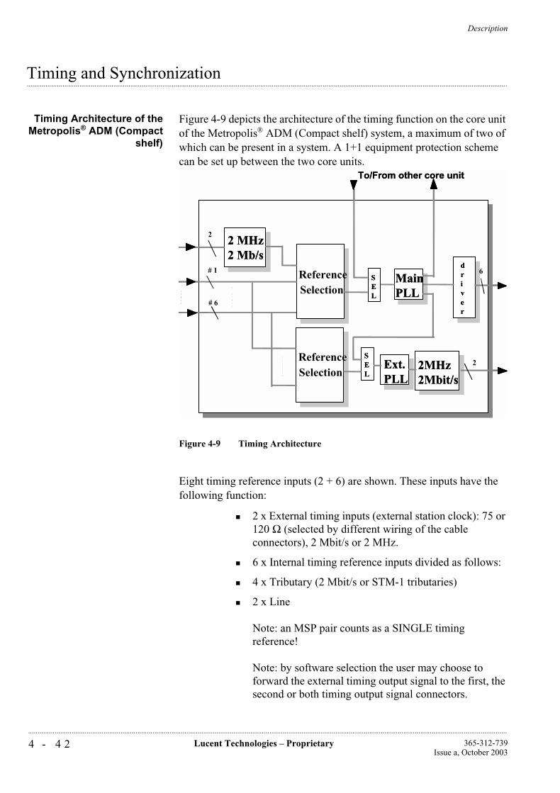
Description
4 - 4 2 Lucent Technologies – Proprietary 365-312-739Issue a, October 2003
..............................................................................................................................................................................................................................................................
...............................................................................................................................................................................................................................................................Timing and Synchronization
Timing Architecture of theMetropolis® ADM (Compact
shelf)
Figure 4-9 depicts the architecture of the timing function on the core unit of the Metropolis® ADM (Compact shelf) system, a maximum of two of which can be present in a system. A 1+1 equipment protection scheme can be set up between the two core units.
Figure 4-9 Timing Architecture
Eight timing reference inputs (2 + 6) are shown. These inputs have the following function:
2 x External timing inputs (external station clock): 75 or 120 Ω (selected by different wiring of the cable connectors), 2 Mbit/s or 2 MHz.
6 x Internal timing reference inputs divided as follows:
4 x Tributary (2 Mbit/s or STM-1 tributaries)
2 x Line
Note: an MSP pair counts as a SINGLE timing reference!
Note: by software selection the user may choose to forward the external timing output signal to the first, the second or both timing output signal connectors.
2
2
2 MHz2 Mb/s
2MHz2Mbit/s
6# 1
# 6
ReferenceSelection
ReferenceSelection
SEL
SEL
MainPLL
Ext.PLL
To/From other core unit
driver
2
2
2 MHz2 Mb/s2 MHz2 Mb/s
2MHz2Mbit/s2MHz2Mbit/s
6# 1
# 6
ReferenceSelection
ReferenceSelection
SEL
SEL
SEL
SEL
MainPLLMainPLL
Ext.PLLExt.PLL
To/From other core unit
driver
driver

Description
4 - 4 3Lucent Technologies – Proprietary365-312-739Issue a, October 2003
..............................................................................................................................................................................................................................................................
Two PLLs (phase lock loops), or station equipment clocks (SECs), are shown: one is the main PLL; the central clock driving six timing output ports, and the other the External PLL, driving two timing output ports.
The signal driving the individual PLLs can be selected as follows:
for the MAIN PLL: out of either the sync. signal provided by the other (protect) core unit or out of the reference signal selected by the reference selector shown to its left.
for the EXT. PLL: out of either the sync. signal provided by the MAIN PLL or out of the reference signal selected by the reference selector shown to its left.
Hence it is possible to select individual timing references for the outgoing station clock signals and for the internal reference clock signals. Reference selections are software selectable by the user.
Timing modes As shown in figure 4-10, the system can be provisioned for the following synchronization conditions / modes:
Add/Drop or Terminal application:
• Free running from an internal oscillator (FR)
• Internal Timing from an incoming line or tributary signal (lower order)
• External Timing, timed from an external 2 MHz or 2 Mbit/s clock signal (lower order)
• Hold-over mode (HO).
Figure 4-10 Timing Modes (Free running selected)
Hold-overmemory
PLL
HO
FR
LO

Description
4 - 4 4 Lucent Technologies – Proprietary 365-312-739Issue a, October 2003
..............................................................................................................................................................................................................................................................
The user can select the system to function in any one of the three sync. modes specified above. This selection can be done by software (user input) or be fully automatically. If set to automatic, the system automatically switches to hold-over mode if the input timing reference signal fails.
Free Running operation(FR)
The Metropolis® ADM (Compact shelf) is designed to operate without any external synchronization reference in the free running mode. In the free running mode (switch set to FR in figure 4-10), the core unit derives timing from an internal station equipment clock (SEC) oscillator. The internal SEC oscillator’s long-term accuracy is higher than 4.6 ppm. The core unit generates and distributes the timing signals to the interface circuit packs.
Locked mode (LO) Locked-to-line or tributary operation (with hold-over).
In the locked-to-line or tributary timing mode (switch set to LO in figure 4-10), the system derives timing from the incoming line or tributary signals. In turn, the core unit generates timing signals and distributes them to the transmission circuit packs.
The signal references are continuously monitored for error-free operation. If the working line or tributary reference in a protected system becomes corrupted, the core unit selects the protection line / tributary reference without causing service degradation. If both references fail, the PLL circuit holds the on-board oscillator frequency at the last good reference sample while the references are repaired, (hold-over mode: switch set to HO in figure 4-10 automatically!). This mechanism is provided so that operation with or without an external clock can be easily accommodated.
In both timing modes, the core unit can also provide two synchronization outputs to other central office equipment.
Locked to External timing reference Operation (with hold-over)
In the external timing mode (switch set to LO in figure 4-10), each core unit accepts a 2 MHz or 2 Mbit/s synchronization reference signal from a 4.6 ppm or better station clock. These references synchronize the local terminal. Within the core unit, a highly stable PLL circuit removes any transient impairments from the 2 MHz or 2 Mbit/s reference for improved jitter performance.
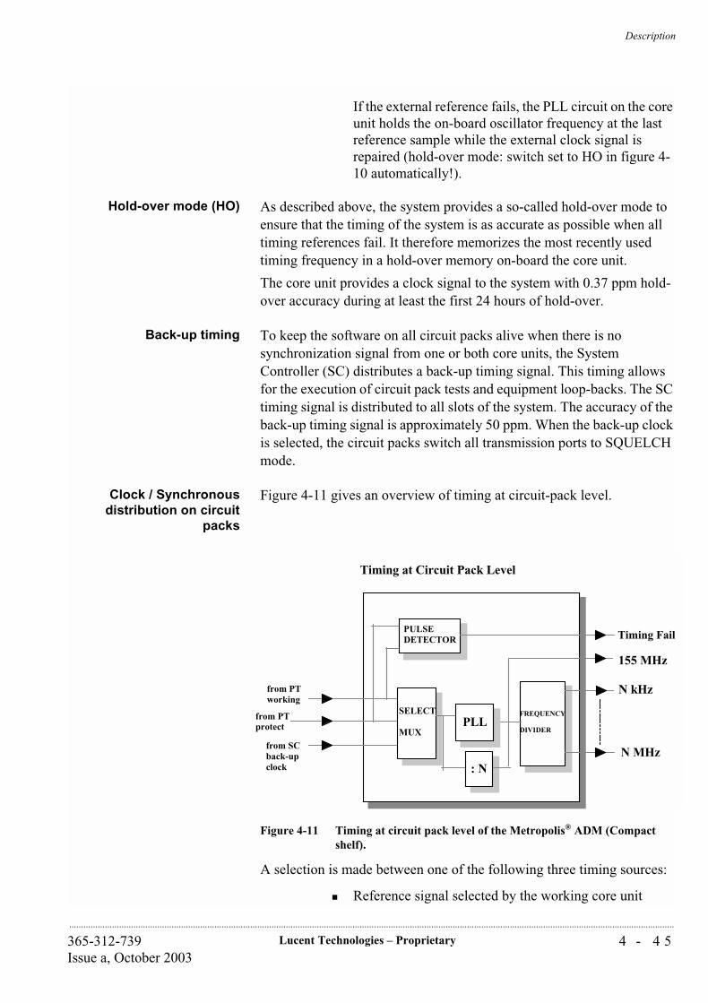
Description
4 - 4 5Lucent Technologies – Proprietary365-312-739Issue a, October 2003
..............................................................................................................................................................................................................................................................
If the external reference fails, the PLL circuit on the core unit holds the on-board oscillator frequency at the last reference sample while the external clock signal is repaired (hold-over mode: switch set to HO in figure 4-10 automatically!).
Hold-over mode (HO) As described above, the system provides a so-called hold-over mode to ensure that the timing of the system is as accurate as possible when all timing references fail. It therefore memorizes the most recently used timing frequency in a hold-over memory on-board the core unit.
The core unit provides a clock signal to the system with 0.37 ppm hold-over accuracy during at least the first 24 hours of hold-over.
Back-up timing To keep the software on all circuit packs alive when there is no synchronization signal from one or both core units, the System Controller (SC) distributes a back-up timing signal. This timing allows for the execution of circuit pack tests and equipment loop-backs. The SC timing signal is distributed to all slots of the system. The accuracy of the back-up timing signal is approximately 50 ppm. When the back-up clock is selected, the circuit packs switch all transmission ports to SQUELCH mode.
Clock / Synchronousdistribution on circuit
packs
Figure 4-11 gives an overview of timing at circuit-pack level.
Figure 4-11 Timing at circuit pack level of the Metropolis® ADM (Compact shelf).
A selection is made between one of the following three timing sources:
Reference signal selected by the working core unit
Timing at Circuit Pack Level WaveStarTM ADM 16/1
FREQUENCY
DIVIDER
Timing Fail
N kHz
N MHz
from PTworking
from PTprotect
from SCback-upclock
155 MHz
SELECT
MUXPLL
: N
PULSEDETECTOR
Description
4 - 4 6 Lucent Technologies – Proprietary 365-312-739Issue a, October 2003
..............................................................................................................................................................................................................................................................
Reference signal selected by the protecting core unit
Back-up clock signal derived from the SC.
All timing signals are checked for availability and if a signal fails then message ‘Timing Fail’ (including appropriate source that’s missing) is sent to the on-board function controller (FC). Then the FC immediately initiates the command to switch to the system’s back-up timing and all transmission ports are switched off (squelch mode). Switching between the input references is non-revertive.
A PLL on the circuit pack itself locks to the selected timing source and supplies the circuit pack with all necessary frequencies.
Description
4 - 4 7Lucent Technologies – Proprietary365-312-739Issue a, October 2003
..............................................................................................................................................................................................................................................................
...............................................................................................................................................................................................................................................................Redundancy and Protection
Equipment Protection(Redundancy)
To enhance the over-all reliability of the system, equipment redundancy can be applied. The FIT rate numbers are specified for each unit in section 10 of this manual.
The core of the system functionality consists of Optical line interface (except CC/PT-64/32), Cross-connection unit and the Power and Timing unit, and can be duplicated if so required. A switch-over between the Core units, causes a hit in the traffic of at most 50 ms.
To complete equipment redundancy, most of the electrical tributary interface circuit packs can be provided with equipment protection as well:
1.5 Mbit/s, 2 Mbit/s Interface circuit packs can be 1:N (N=max. 4) equipment protected.In the event of failure in any circuit of an interface circuit pack, all traffic carried by this pack is switched to the protecting circuit pack.
34/45 Mbit/s Interface circuit packs can be 1+1 equipment protected.In the event of failure in the working interface circuit pack, all traffic carried by this pack is switched to the protecting circuit pack.
155.520 Mbit/s Interface circuit packs can be 1+1 equipment protected.In the event of failure in the working interface circuit pack, all traffic carried by this pack is switched to the protecting circuit pack.
Protection against failures at the network level, e.g. cable breaks or failures in other equipment in the network, requires network level protection schemes. The Metropolis® ADM (Compact shelf) system supports the following network level protection schemes:
8. Multiplex section protection (MSP) for STM-1/4 optical tributary
9. Multiplex Section Shared Protection Ring (MS-SPRing)
10. Sub-network connection protection (SNCP)
In addition a number of features are supported to optimize the network protection for many applications:
1. Access of protection bandwidth in MS-SPRing
2. Tailoring of the MS-SPRing bandwidth (selective MS-SPRing)
3. Dual node interworking with drop & continue
Description
4 - 4 8 Lucent Technologies – Proprietary 365-312-739Issue a, October 2003
..............................................................................................................................................................................................................................................................
At the network level these features allow to make the most efficient use of the available bandwidth, while still providing adequate protection for a very large number of applications.
Multiplex Section SharedProtection Ring (MS-
SPRing)
MS-SPRing is a shared protection mechanism, which means that the protection bandwidth is shared by multiple connections. MS-SPRing can operate in a ring network only and it operates at the VC-4 level. The protection is applicable from the node where the VC-4 enters the ring till the node where the VC-4 leaves the ring. The Metropolis® ADM (Compact shelf) supports 2 fiber MS-SPRing on its STM-16 aggregate interfaces, so it supports 2 fiber MS-SPRing protected STM-16 rings. The maximum number of nodes in the MS-SPRing can be 16, the minimum can be 2. The MS-SPRing protocol uses an APS channel for signalling, which is transmitted in K1/K2 bytes in the Multiplex Section overhead, according to ITU-T Recommendation G.841. The protocol provides protection within 60 ms (10ms defect detection time and 50ms switching time).
In MS-SPRing protected rings it is useful to define (bi-directional) channels. There are 16 such channels in an STM-16 MS-SPRing. A channel can be thought of as the capacity of a single, bi-directional, STM-1 going fully around the ring in a certain fixed position within the STM-16 connections that make up the ring. Each channel can transport one VC-4 payload in both directions at a time. If a VC-4 is added/dropped from the channel in a node, it can pick up a new VC-4 there and carry it further around the ring. These channels can be numbered #1 through #16.
In the MS-SPRing the channels #1 through #8 are available for protected VC-4 traffic. They are protected by the capacity provided by channels #9 through #16, on a pair-by-pair basis, so channel #9 protects channel #1, #10 protects #2, etc. up to channel #16 protecting #9. In the Sapphire release, it is allowed to decide per channel pair (1,9), (2,10) etc. whether or not it is part of the MS-SPRing. An application for this exclusion of a certain pair from MS-SPRing could be to avoid double protection on an connection that is already VC-4 SNC protected and thus save bandwidth.
To summarize, within an MS-SPRing the bandwidth can be split in three parts: Worker capacity, protection capacity and un-protected capacity. Each channel pair can be unprotected pair or a worker/protection pair. In the latter case the lower channel number represents the worker capacity and the higher channel number the protection capacity.
The protection capacity can be accessed and used for transport of low priority traffic (“extra traffic”), to utilize the bandwidth even better. Under failure conditions this traffic is lost (“pre-empted”).
At the network level, the efficiency of the MS-SPRing protection mechanism is its most obvious advantage. The degree of bandwidth
Description
4 - 4 9Lucent Technologies – Proprietary365-312-739Issue a, October 2003
..............................................................................................................................................................................................................................................................
saving over e.g. a VC-4 SNCP scheme depends on the traffic pattern. The most dramatic improvement is in the case where the traffic is mostly between adjacent ring nodes. On the other hand, if all traffic is destined for a specific hub-node, there is no bandwidth advantage compared to VC-4 SNCP. For uniform traffic patterns the result is between these extremes.
1+1 Multiplex SectionProtection (MSP)
1+1 Multiplex section protection is a relatively simple scheme to protect an STM-N link between two adjacent SDH network elements (excluding regenerators) by providing dedicated protection capacity. The MSP protocol exists in different versions: G.841/Clause 7 (mostly used internationally), G.841/Annex B (Japan) and SONET-style, according to ANSI T1.105 and Telcordia GR-253-CORE (US, Canada). To maximize the interworking and application possibilities, the current release of Metropolis® ADM (Compact shelf) supports G.841/Clause 7 on STM-1 and STM-4 optical tributary interfaces.
The following parameters can be provisioned and commands can be issued for each 1+1 MSP protection process:
Operation: Revertive operation or Non-revertive operation. Revertive operation means that after repair of a failure the traffic is switched back to the “worker” capacity. Non-revertive operation
Wait-to-Restore time. The time that should elapse before a switch back to “worker” is initiated after repair of a failure. The timer can be provisioned between 0 and 60 minutes in 1 minute increments. The default is 5 minutes. Only available with revertive operation.
Control: Bi-directional or Uni-directional control. Uni-directional control means that each receive end decides separately which traffic stream is active. Bi-directional control means that both ends switch in conjunction. In uni-directional schemes the traffic in one direction can be selected from the “worker” and in the other direction from the “protection” capacity.
Force switch command. By issuing a force switch the user forces the traffic to either “worker” (force to worker) or to “protection” (force to protection).
Manual switch command. By issuing a manual switch the user requests the traffic to either “worker” (manual to worker) or to “protection” (manual to protection) side. The request is only honored if the designated capacity is not affected by “Signal Fail” or “Signal Degrade” defects.
Clear command. Clears all pending requests.
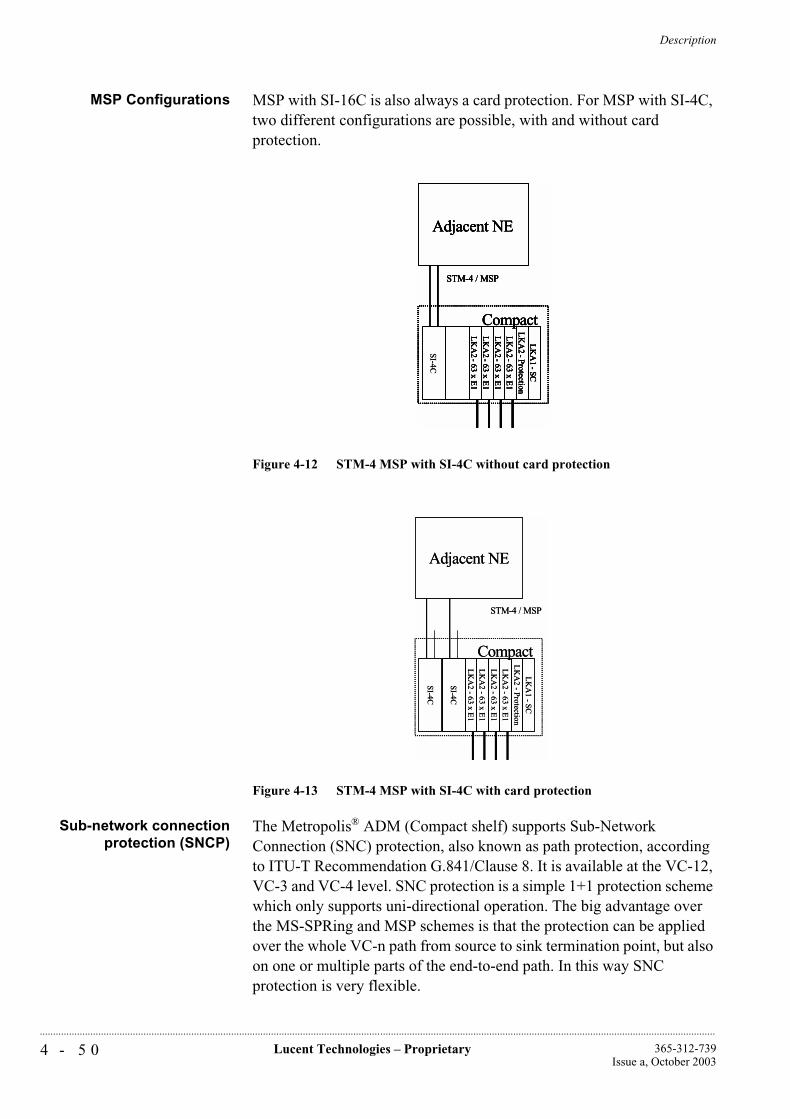
Description
4 - 5 0 Lucent Technologies – Proprietary 365-312-739Issue a, October 2003
..............................................................................................................................................................................................................................................................
MSP Configurations MSP with SI-16C is also always a card protection. For MSP with SI-4C, two different configurations are possible, with and without card protection.
Figure 4-12 STM-4 MSP with SI-4C without card protection
Figure 4-13 STM-4 MSP with SI-4C with card protection
Sub-network connectionprotection (SNCP)
The Metropolis® ADM (Compact shelf) supports Sub-Network Connection (SNC) protection, also known as path protection, according to ITU-T Recommendation G.841/Clause 8. It is available at the VC-12, VC-3 and VC-4 level. SNC protection is a simple 1+1 protection scheme which only supports uni-directional operation. The big advantage over the MS-SPRing and MSP schemes is that the protection can be applied over the whole VC-n path from source to sink termination point, but also on one or multiple parts of the end-to-end path. In this way SNC protection is very flexible.
SI-4C
LK
A2 -
63 x E1
LK
A2 -
63 x E1
LK
A2 -
63 x E1
LK
A2 -
63 x E1
LK
A2 -Protection
LK
A1 -SC
Compact
STM-4 / MSP
Adjacent NE
LK
A2 -
63 x E1
LK
A2 -
63 x E1
LK
A2 -
63 x E1
LK
A2 -
63 x E1
LK
A2 -Protection
LK
A1 -SC
Compact
STM-4 / MSP
Adjacent NE
SI-4C
LK
A2 -
63 x E1
LK
A2 -
63 x E1
LK
A2 -
63 x E1
LK
A2 -
63 x E1
LK
A2 -Protection
LK
A1 -SC
Compact
STM-4 / MSP
Adjacent NE
LK
A2 -
63 x E1
LK
A2 -
63 x E1
LK
A2 -
63 x E1
LK
A2 -
63 x E1
LK
A2 -Protection
LK
A1 -SC
Compact
STM-4 / MSP
Adjacent NE
SI-4C
LK
A2 -
63 x E1
LK
A2 -
63 x E1
LK
A2 -
63 x E1
LK
A2 -
63 x E1
LK
A2 -
Protection
LK
A1 -
SC
Compact
STM-4 / MSP
Adjacent NE
SI-4C
SI-4C
LK
A2 -
63 x E1
LK
A2 -
63 x E1
LK
A2 -
63 x E1
LK
A2 -
63 x E1
LK
A2 -
Protection
LK
A1 -
SC
Compact
STM-4 / MSP
Adjacent NE
SI-4C
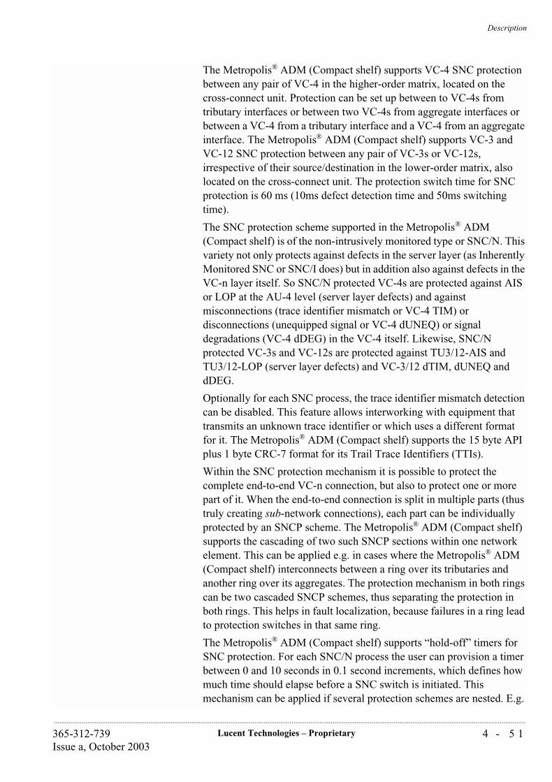
Description
4 - 5 1Lucent Technologies – Proprietary365-312-739Issue a, October 2003
..............................................................................................................................................................................................................................................................
The Metropolis® ADM (Compact shelf) supports VC-4 SNC protection between any pair of VC-4 in the higher-order matrix, located on the cross-connect unit. Protection can be set up between to VC-4s from tributary interfaces or between two VC-4s from aggregate interfaces or between a VC-4 from a tributary interface and a VC-4 from an aggregate interface. The Metropolis® ADM (Compact shelf) supports VC-3 and VC-12 SNC protection between any pair of VC-3s or VC-12s, irrespective of their source/destination in the lower-order matrix, also located on the cross-connect unit. The protection switch time for SNC protection is 60 ms (10ms defect detection time and 50ms switching time).
The SNC protection scheme supported in the Metropolis® ADM (Compact shelf) is of the non-intrusively monitored type or SNC/N. This variety not only protects against defects in the server layer (as Inherently Monitored SNC or SNC/I does) but in addition also against defects in the VC-n layer itself. So SNC/N protected VC-4s are protected against AIS or LOP at the AU-4 level (server layer defects) and against misconnections (trace identifier mismatch or VC-4 TIM) or disconnections (unequipped signal or VC-4 dUNEQ) or signal degradations (VC-4 dDEG) in the VC-4 itself. Likewise, SNC/N protected VC-3s and VC-12s are protected against TU3/12-AIS and TU3/12-LOP (server layer defects) and VC-3/12 dTIM, dUNEQ and dDEG.
Optionally for each SNC process, the trace identifier mismatch detection can be disabled. This feature allows interworking with equipment that transmits an unknown trace identifier or which uses a different format for it. The Metropolis® ADM (Compact shelf) supports the 15 byte API plus 1 byte CRC-7 format for its Trail Trace Identifiers (TTIs).
Within the SNC protection mechanism it is possible to protect the complete end-to-end VC-n connection, but also to protect one or more part of it. When the end-to-end connection is split in multiple parts (thus truly creating sub-network connections), each part can be individually protected by an SNCP scheme. The Metropolis® ADM (Compact shelf) supports the cascading of two such SNCP sections within one network element. This can be applied e.g. in cases where the Metropolis® ADM (Compact shelf) interconnects between a ring over its tributaries and another ring over its aggregates. The protection mechanism in both rings can be two cascaded SNCP schemes, thus separating the protection in both rings. This helps in fault localization, because failures in a ring lead to protection switches in that same ring.
The Metropolis® ADM (Compact shelf) supports “hold-off” timers for SNC protection. For each SNC/N process the user can provision a timer between 0 and 10 seconds in 0.1 second increments, which defines how much time should elapse before a SNC switch is initiated. This mechanism can be applied if several protection schemes are nested. E.g.
Description
4 - 5 2 Lucent Technologies – Proprietary 365-312-739Issue a, October 2003
..............................................................................................................................................................................................................................................................
a VC-12 SNCP scheme is used on top of an MS-SPRing. Normally, the MS-SPRing reacts within 60 ms (10ms defect detection time and 50ms switching time). By provisioning a 100 ms hold-off time on the VC-12 SNC protection, the MS-SPRing is given the opportunity to react to a failure first. This avoids multiple switches.
Dual node interworkingwith drop & continue
The MS-SPRing protection mechanism offers very efficient protection but since the protection span is limited to a single ring network, there is need for a mechanism to couple ring networks in a way that avoids single points of failure, to allow longer end-to-end protected paths. This mechanism is called Dual Node Interworking with Drop & Continue. The advantages of using this mechanism are:
Protected interconnection between MS-SPRing rings possible, thus allowing longer end-to-end protected spans, without single point of failure on each ring interconnect.
Possibility to interconnect the MS-SPRing scheme to the SNCP scheme, without introducing a single point of failure. This allows the user the flexibility to use the protection scheme of choice in each network part, while avoiding double protection.
Independence of the protection mechanisms in different network parts, which results in protection switches relatively close to the failure, so in principle easier to fault-locate.
A higher availability, compared to end-to-end SNCP protection schemes. Especially on very long connections, more protection against multiple failure is provided (as long as there is at most one failure per protected sub-network).
Dual Node Interworking with Drop and Continue is a mechanism described in ITU-T Recommendation G.842, and it is realized by connecting the two networks in question in two different locations in such a way that if one location fails completely, the traffic can still reach the other network via the second interconnection.
The Metropolis® ADM (Compact shelf) supports two different DNI configurations:
1. Between two MS-SPRing rings. The ring interconnection consists in this case of four network elements. Two network elements in each ring which are pair wise connected (see figure 4-14)
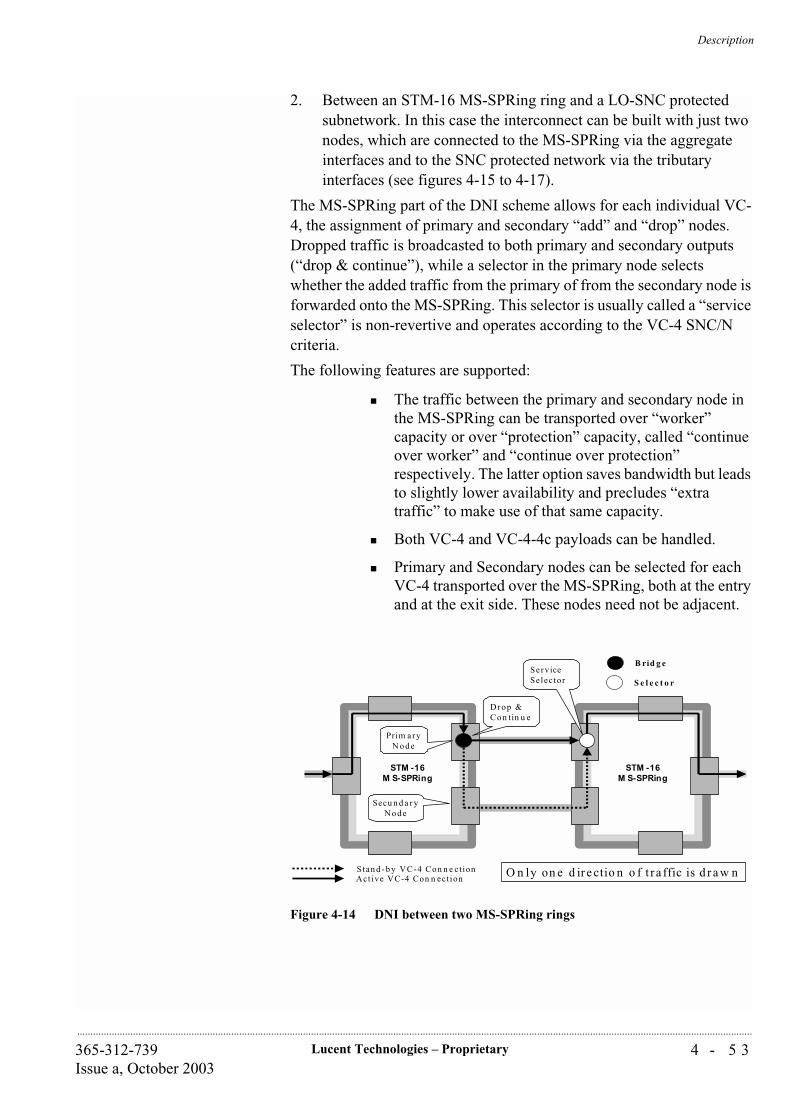
Description
4 - 5 3Lucent Technologies – Proprietary365-312-739Issue a, October 2003
..............................................................................................................................................................................................................................................................
2. Between an STM-16 MS-SPRing ring and a LO-SNC protected subnetwork. In this case the interconnect can be built with just two nodes, which are connected to the MS-SPRing via the aggregate interfaces and to the SNC protected network via the tributary interfaces (see figures 4-15 to 4-17).
The MS-SPRing part of the DNI scheme allows for each individual VC-4, the assignment of primary and secondary “add” and “drop” nodes. Dropped traffic is broadcasted to both primary and secondary outputs (“drop & continue”), while a selector in the primary node selects whether the added traffic from the primary of from the secondary node is forwarded onto the MS-SPRing. This selector is usually called a “service selector” is non-revertive and operates according to the VC-4 SNC/N criteria.
The following features are supported:
The traffic between the primary and secondary node in the MS-SPRing can be transported over “worker” capacity or over “protection” capacity, called “continue over worker” and “continue over protection” respectively. The latter option saves bandwidth but leads to slightly lower availability and precludes “extra traffic” to make use of that same capacity.
Both VC-4 and VC-4-4c payloads can be handled.
Primary and Secondary nodes can be selected for each VC-4 transported over the MS-SPRing, both at the entry and at the exit side. These nodes need not be adjacent.
Figure 4-14 DNI between two MS-SPRing rings
STM -16M S-SPRing
STM -16M S-SPRing
D r o p & C o n tin u e
Serv iceSelec tor
Prim aryN o d e
Secu n d a r yN o d e
Act ive VC-4 Con n ect ionStan d - b y VC-4 Con n e ct ion O n ly on e d ir e ctio n o f t r a ffic is d r a w n
B rid g e
S e l e c t o r
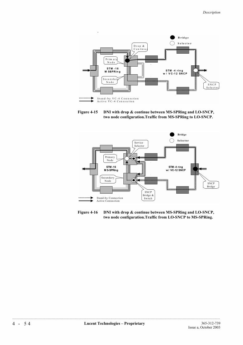
Description
4 - 5 4 Lucent Technologies – Proprietary 365-312-739Issue a, October 2003
..............................................................................................................................................................................................................................................................
.
Figure 4-15 DNI with drop & continue between MS-SPRing and LO-SNCP, two node configuration.Traffic from MS-SPRing to LO-SNCP.
Figure 4-16 DNI with drop & continue between MS-SPRing and LO-SNCP, two node configuration.Traffic from LO-SNCP to MS-SPRing.
STM - 1 6M S-SPRin g STM -4 r in g
w / V C-1 2 SN C P
P r im a r yN o d e
S e c u n d a r yN o d e
A c t iv e V C - 4 C o n n e c t io nS t a n d - b y V C - 4 C o n n e c t io n
D r o p & C o n t i n u e
S N C PS e le c t o r
B r i d g e
S e l e c t o r
STM -16M S-SPRing
STM -4 ringw / VC-12 SNCP
PrimaryNode
SecundaryNode
Active Con n e ctionStand-by Connection
ServiceSelector
SNCPBridge
SNCPBridge &Switch
Bridge
Se lec tor
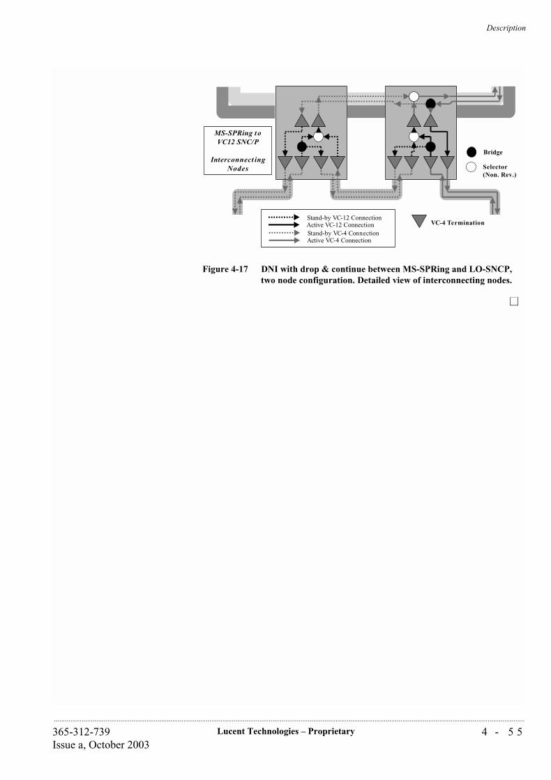
Description
4 - 5 5Lucent Technologies – Proprietary365-312-739Issue a, October 2003
..............................................................................................................................................................................................................................................................
Figure 4-17 DNI with drop & continue between MS-SPRing and LO-SNCP, two node configuration. Detailed view of interconnecting nodes.
MS-SPRing toVC12 SNC/P
Interconnect ingNodes
Active VC-12 ConnectionStand-by VC-12 Connection
Active VC-4 ConnectionStand-by VC-4 Connection
VC-4 Termination
Bridge
Selector(Non. Rev.)

Lucent Technologies – ProprietarySee notice on first page
365-312-739Issue a, October 2003
...........................................................................................................................................................................................................................................................
Description
5 - 1Lucent Technologies – Proprietary365-312-739Issue a, October 2003
..............................................................................................................................................................................................................................................................
5 Operations Administration Maintenance and Provisioning
...............................................................................................................................................................................................................................................................Overview
This chapter defines the “Maintenance Philosophy” outlining the various features available for monitoring and maintaining the Metropolis® ADM (Compact shelf).
Operations Administration Maintenance and Provisioning
5 - 2 Lucent Technologies – Proprietary 365-312-739Issue a, October 2003
..............................................................................................................................................................................................................................................................
...............................................................................................................................................................................................................................................................Operations
Element and Network Management aspects of Metropolis® ADM (Compact shelf) are based on the SDH concepts as laid down in ITU-T recommendations, for instance G.784.
Local operations facilities are based on long-term experience and several commonly applied operations and alarms procedures.
The Metropolis® ADM (Compact shelf) is additionally provided with advanced diagnostic features which can be used for equipment performance checks and detailed fault location.
Introduction The Metropolis® ADM (Compact shelf) maintenance procedures are built on two levels of system information and control. The first maintenance tier is provided by the:
User panel
Circuit pack faceplate LEDs
Operations Interfaces.
These features enable maintenance tasks (that is, circuit pack replacement) to be performed without an ITM-CIT (Craft Interface Terminal) or external test equipment. The second maintenance tier uses the ITM-CIT to retrieve detailed reports about alarms and status, and system configuration for local terminals.
User Panel The User Panel of the Metropolis® ADM (Compact shelf) is integrated in the faceplate of the System Controller (SC) circuit pack, as shown in figure 5-1. Lightguides are used to make the alarm and status indicators on the SC visible with the front door of the subrack closed. Buttons can

Operations Administration Maintenance and Provisioning
5 - 3Lucent Technologies – Proprietary365-312-739Issue a, October 2003
..............................................................................................................................................................................................................................................................
be operated with the door closed. The user panel provides system-level information.
Figure 5-1 Metropolis® ADM (Compact shelf) user panel: SC faceplate
User Panel LEDs andConnector
The User Panel LEDs show the following system information:
FAIL: A red FAIL LED is lit when at least one prompt or deferred maintenance alarm exists.
PWR: A green POWER LED indicates that voltage is present on at least one of the -48V secondary power-distribution feeds inside the system.
The active alarm level is shown by LEDs for
• PRPT alarms: A red PROMPT LED indicates a transmission affecting malfunction.
• DEF alarms: A red DEFERRED LED indicates a no transmission affecting malfunction
• INFO alarms: A yellow INFO LED indicates a failure that is not located within the terminal. If only the INFO indicator is lit, no immediate maintenance action is required. The alarm severities (CRITICAL, PROMPT, DEFERRED and INFO) of the fault messages, are user provisionable.
ABN: A yellow ABNORMAL LED indicates a the existence of abnormal conditions initiated in the Network Element, for example: a protection lock out, forced switch, manual switch, protection line in use, alarms disconnected, installation self-test failed.
LED
LEDLEDLEDLED
LEDswitchLEDswitch
LED
LEDFAIL
DISC
SUPP
PWR
PRPT
DEF
INFO
ABN
CIT
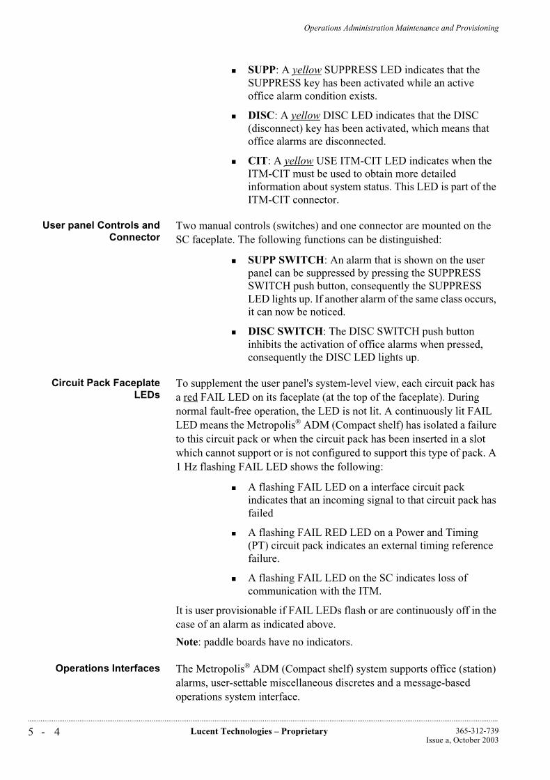
Operations Administration Maintenance and Provisioning
5 - 4 Lucent Technologies – Proprietary 365-312-739Issue a, October 2003
..............................................................................................................................................................................................................................................................
SUPP: A yellow SUPPRESS LED indicates that the SUPPRESS key has been activated while an active office alarm condition exists.
DISC: A yellow DISC LED indicates that the DISC (disconnect) key has been activated, which means that office alarms are disconnected.
CIT: A yellow USE ITM-CIT LED indicates when the ITM-CIT must be used to obtain more detailed information about system status. This LED is part of the ITM-CIT connector.
User panel Controls andConnector
Two manual controls (switches) and one connector are mounted on the SC faceplate. The following functions can be distinguished:
SUPP SWITCH: An alarm that is shown on the user panel can be suppressed by pressing the SUPPRESS SWITCH push button, consequently the SUPPRESS LED lights up. If another alarm of the same class occurs, it can now be noticed.
DISC SWITCH: The DISC SWITCH push button inhibits the activation of office alarms when pressed, consequently the DISC LED lights up.
Circuit Pack FaceplateLEDs
To supplement the user panel's system-level view, each circuit pack has a red FAIL LED on its faceplate (at the top of the faceplate). During normal fault-free operation, the LED is not lit. A continuously lit FAIL LED means the Metropolis® ADM (Compact shelf) has isolated a failure to this circuit pack or when the circuit pack has been inserted in a slot which cannot support or is not configured to support this type of pack. A 1 Hz flashing FAIL LED shows the following:
A flashing FAIL LED on a interface circuit pack indicates that an incoming signal to that circuit pack has failed
A flashing FAIL RED LED on a Power and Timing (PT) circuit pack indicates an external timing reference failure.
A flashing FAIL LED on the SC indicates loss of communication with the ITM.
It is user provisionable if FAIL LEDs flash or are continuously off in the case of an alarm as indicated above.
Note: paddle boards have no indicators.
Operations Interfaces The Metropolis® ADM (Compact shelf) system supports office (station) alarms, user-settable miscellaneous discretes and a message-based operations system interface.
Operations Administration Maintenance and Provisioning
5 - 5Lucent Technologies – Proprietary365-312-739Issue a, October 2003
..............................................................................................................................................................................................................................................................
Office (Station) AlarmInterface
The office-alarms interface is a set of discrete relays (floating contacts) that control office audible and visible alarms. The relays are located on the system controller (SC) circuit pack. The relays are activated when a PROMPT or DEFERRED Maintenance Alarm situation exists in the system to activate: End-Of-Suite, Bay-top, Station alarms and Miscellaneous maintenance information. They are made available via a connector on the interconnection panel: both connectable and non-connectable outputs are available. The miscellaneous conditions consist of suppressed alarms present, disconnect function activated and main--controller removed.
Miscellaneous Discretes The miscellaneous discrete interface allows an operations system to control and monitor equipment co-located with the Metropolis® ADM (Compact shelf) system through a series of input (MDIs) and output (MDOs) contact closures. Eight miscellaneous discrete inputs can monitor such conditions as open doors, high temperature or high humidity, and four miscellaneous discrete control outputs can control equipment such as fans and generators. The statuses of the miscellaneous discrete environmental inputs are reported to the WaveStar® ITM-SC network element management system. It is possible to activate these miscellaneous discrete control outputs from the WaveStar® ITM-SC network element management system when the system reports an alarm condition. Miscellaneous discretes are provided to the user through a connector at the interconnection panel.
MDI/MDO Management It is possible for the user to control all MDOs of all Metropolis® ADM (Compact shelf) under a single WaveStar® ITM-SC by means of a scripting facility. These scripts can be edited, activated and de-activated during runtime. The scripts are sufficiently flexible to allow activation or de-activation of certain MDOs based on combinations of certain alarms or MDI statuses on those network elements. Strings can be assigned to MDOs and their status is visible to the user.
Network ManagementInterfaces
Q-LAN interfaces: The Q-LAN interfaces enable network-oriented communication between the Metropolis® ADM (Compact shelf) and the WaveStar®
ITM-SC and Navis® Optical NMS management. This is the standardized interface to Navis® Optical Management Solution.
The 10 Base-T interfaces for Q-LAN is located at the interconnection panel.

Operations Administration Maintenance and Provisioning
5 - 6 Lucent Technologies – Proprietary 365-312-739Issue a, October 2003
..............................................................................................................................................................................................................................................................
CIT-F (Craft Interface Terminal) Interfaces: One RJ-45 interface is presented at the customer interface area. The electrical characteristics of CIT-F port comply with V.10.
Additional OperationalFeatures
Loop-backs: Within the Metropolis® ADM (Compact shelf) loop-backs are possible at tributary interface signal level or VC-n level. The tributary interface signal level can be used for far-end / near-end loop-backs and VC-n for a loop-back within the cross-connect. The 2 Mbit/s tributary interfaces have both far-end and near-end loop-back possibilities. The STM-1o and STM-4o interfaces support far-end loopback (in AU-3 conversion mode only) and near-end loopback. For AU-4 applications loopbacks are made on the cross-connect. Far-end refers to looping back the signal coming from the cross-connect back to the cross-connect via a tributary. Near-end refers to directly looping back incoming signals as outgoing signals.
Loop-backs are also allowed when the optical STM-1 or STM-4 interfaces are being provisioned as 1+1 MSP protected.
User channels: The STM-16/STM-4 section overhead and the VC-3/VC-4 path overhead contain several bytes, for instance E and F bytes, which can be used to provide 64 kbit/s operations channels. The Metropolis® ADM (Compact shelf) provides for a maximum of six transparent 64 kbit/s channels selected from the following overhead bytes:
E1 and E2 bytes: The use of which is mainly referred to as: engineering order wire channels
F1 and F2 bytes: The use of which is mainly referred to as: user channels
MS-NU and RS-NU bytes: The use of which is mainly referred to as: National Use bytes. The selected four overhead byte channels are fed via the System Controller to the connection board and are available via: 2 x G.703 co-directional interfaces and 2 x V.11 contra-directional interfaces.
See chapter 9 for more details on the overhead bytes.
Remote login/single endedoperations/NSAP
addresses (programmable)
The interfaces for the CIT-F (F-interface) provide the facility to log onto the local Metropolis® ADM (Compact shelf). Via the ITM-CIT it is also possible to remote login to other Metropolis® ADM (Compact shelf), Metropolis® ADM, WaveStar® TM 1, WaveStar® AM 1 and WaveStar® AM 1 Plus.
Operations Administration Maintenance and Provisioning
5 - 7Lucent Technologies – Proprietary365-312-739Issue a, October 2003
..............................................................................................................................................................................................................................................................
The WaveStar® ITM-SC can perform control and provisioning tasks remotely.
The NSAP address is programmable to enable compatibility with the NSAP addresses of existing products like ISM, SLM, PHASE, Metropolis® ADM etc. This allows DCC interworking with other kinds of equipment.
Data communicationschannel
This network operations capability uses the SDH section (MSOH, D4-D12 and RSOH, D1-D3) data communication channel (DCC) bytes. Management interface dialogs and operations interface messages travel in these DCC bytes on each STM-N interface.
Severity setting for alarmson each termination point
instance
Since different clients pay for different quality of service (QoS), the priority and time to repair can differ for different paths. By setting a higher severity for the alarms on paths that require a high QoS, than for the paths that require a low QoS, the promised QoS can be met better. In the subsection Performance Monitoring the concept of quality of service is explained in more detail.
Support of a multiplexsection trace identifier (J0
byte)
The user can provide a multiplex section trace identifier on all STM-N (N=1,16) outputs of the Metropolis® ADM (Compact shelf) via the WaveStar® ITM-SC or ITM-CIT. In the receive direction an expected value for this trace identifier can be provided. In case of a mismatch a TIM (trace identifier mismatch) alarm is generated an consequent actions are invoked. The TIM detection mechanism can be disabled per interface.
Operations Administration Maintenance and Provisioning
5 - 8 Lucent Technologies – Proprietary 365-312-739Issue a, October 2003
..............................................................................................................................................................................................................................................................
...............................................................................................................................................................................................................................................................Administration
Version Recognition The system provides automatic version recognition of all hardware and software installed on the system. The system can report the type, version and serial number of the circuit pack installed in each slot. Each circuit pack identification code is stored on the circuit pack itself and is accessible by the system controller.
User login security The WaveStar® ITM-SC network element management system provides security protection against unauthorized access to the network element functions (for example provisioning). This feature controls access to the system on an individual user basis including:
Login ID and password assignment: This requires the user to enter a valid Login ID and password to access the system.
User authorization levels: Provides three levels of access on a per session basis:
• Administrator: The Administrator is authorized to perform WaveStar® ITM-SC system control activities. This includes starting and stopping management of the transmission network. Only this user can administer other users of the WaveStar® ITM-SC application. In addition, backups can be created or restored by this user.
• Operator: Authorized for all retrieval and operate commands that are not service affected and does not imply system configuration changes.
• Supervisor: Authorized for all retrieval, provisioning and operate commands, as well service and not service affected handling, with the exception of provisioning security data and software downloads.
Software Upgrades Upgrading and reconfiguring the Metropolis® ADM (Compact shelf) to support new services or to incorporate feature enhancements can easily be implemented by downloading a new software generic via the appropriate (F/Q) Operations interface.
Normally, however, depending on the actual situation, downloading and replacing software generics do not cause service interruption.
Performance Monitoring Performance monitoring can be used for, broadly speaking, two applications. The first application is for maintenance applications, the second application is for “Quality of Service (QoS)” monitoring. The Metropolis® ADM (Compact shelf) performance monitoring features are based upon ITU-T Recommendations G.784, G.826, G.827, G.829,
Operations Administration Maintenance and Provisioning
5 - 9Lucent Technologies – Proprietary365-312-739Issue a, October 2003
..............................................................................................................................................................................................................................................................
M.2101.1, M.2110 and M.2120. All definitions of maintenance parameters are according to G.784 and G.826.
Maintenance Applications The maintenance applications are based on ITU-T Recommendations M.2101.1, M.2110 and M.2120 and are used for “bringing into service (BIS)” and other initial testing procedures and localization/monitoring of under-performing parts of an end-to-end path. To support these applications the Metropolis® ADM (Compact shelf) provides for each performance monitoring process, the current 15 minute interval and current 24 hour interval counts of the BBE (background block errors), ES (errored seconds), SES (severely errored seconds) and UAS (unavailable seconds). In addition the recent history of these parameters remains stored in the network element: the 16 most recent complete 15 minute counts and the 1 most recent complete 24 hour count.
For all current interval counters, thresholds can be set that control the forwarding of threshold report (TR) and reset threshold report (RTR) information to the management system. A TR is generated at the moment that the actual count in a current register crosses the “set” threshold level for the first time since the last RTR. An RTR is generated at the end of the first interval in which the actual count remains below the “clear” threshold. So the TRs and RTRs are generated alternating. In the period between a TR and an RTR the monitored part of the path is considered degraded, while the period between a RTR and a TR it is considered normal. “set” and “clear” thresholds can be assigned by the user via the ITM-CIT or the WaveStar® ITM-SC.
In addition to the parameters above, also the 6 most recent UAPs (unavailable periods) are logged in the system. Each UAP is represented by two timestamps. The first indicates the time of entering “unavailable time” and the second indicates the subsequent entering of “available time”.
For maintenance applications the Metropolis® ADM (Compact shelf) supports the counting, threshold monitoring and logging of all the parameters mentioned above for the incoming traffic direction (or “uni-directional near-end” performance monitoring). Possible monitoring points are VC-12, VC-3 and VC-4 trail terminations points (TTPs) as well as on MS-1, MS-4, MS-16 and RS-16 termination points as well as VC-12, VC-3, VC-4 and VC-4-4c transit points or connection termination points (CTPs). Note that the uni-directional near-end performance monitoring provides the performance of the incoming signal between the signal trail source and the monitoring point.
The BBE, ES, SES, UAS and UAT parameters are derived from the errors in the incoming signal, based on the B1, B2, B3 or V5 (bit 1,2) parity information which is part of the RSOH, MSOH or VC-POH. Periods of unavailable time are, additionally, based on local defects or
Operations Administration Maintenance and Provisioning
5 - 1 0 Lucent Technologies – Proprietary 365-312-739Issue a, October 2003
..............................................................................................................................................................................................................................................................
defects in the incoming signal. For the duration of a period of unavailable time the BBE, ES and SES counters are inhibited.
For each LAN interface the performance of the incoming and outgoing LAN streams (3x8 counters) as well as the incoming and outgoing WAN streams (up to 3x8 counters) are monitored for
incoming dropped packets
bytes sent
bytes received
Quality of serviceapplication
The quality of service (QoS) applications are based on ITU-T Recommendations G.826 and G.827. In contrast with the maintenance application, the QoS application requires a performance assessment of the bi-directional path over longer periods.
To support the QoS application in the network element, the Metropolis® ADM (Compact shelf) provides the logging of the current and most recent 24 hour periods of the UAP, UAP-count (number of unavailable periods) and UAS for the bi-directional connection, whereby the bi-directional connection is considered unavailable as soon as one of the direction is unavailable. In addition, for each monitoring point the BBE, ES and SES counts are reported for both directions individually. So there are nine parameters altogether per bi-directional monitoring point. Note that all six BBE, ES and SES counters are inhibited as soon as the bi-directional connection is unavailable. For this reason the bi-directional counts may differ from the uni-directional counts, even if they are concerning the same path and the same monitoring interval.
Bi-directional performance monitoring comes in two flavours: In “end-points” or TTPs or in “mid-points” or CTPs. The following monitoring points in the Metropolis® ADM (Compact shelf) support bi-directional PM: VC-12 TTPs, VC-3 TTPs and VC-4 TTPs and also VC-12, VC-3, VC-4 and VC-4-4c CTPs.
Bi-directional performance reports in end-points are based on the near-end and far-end (REI, RDI) information received on the incoming signal. Bi-directional performance reports in midpoints are based on the far-end information contained in the incoming signal in both directions of transmission.
Number of PerformanceMonitors
The Metropolis® ADM (Compact shelf) can support 1200 monitoring points simultaneously. These can be randomly selected from all the possible TTPs and CTPs indicated above, counting the “uni-directional near-end” and “bi-directional” applications as different. Once a performance monitoring point is activated the full set of performance parameters is supported. Activating or de-activating a performance monitoring process can be performed from the ITM-CIT or WaveStar®
ITM-SC.
Operations Administration Maintenance and Provisioning
5 - 1 1Lucent Technologies – Proprietary365-312-739Issue a, October 2003
..............................................................................................................................................................................................................................................................
Performance Monitoring on LAN connections (Gigabit Ethernet ports)It is possible to monitor byte and packet related performance parameters on any external Ethernet port and any internal port linked with VC-3/4-Xv channels. The following counters are supported for each port:
Outgoing number of bytes
Incoming number of bytes
Number of incoming packets dropped
Accumulation of counts in 15 min. and 24 hour bins can be selected per port.Recent bins are stored: 16 recent 15 min. bins and 1 recent 24 hours bin.Thresholding (TR/RTR) on counts of dropped incoming packets can be enabled and configured per port.
Performance Monitoring on 10/100BASE-T
On the VC3/VC12 termination points that are connected to a WAN port, the “normal” performance monitoring can be activated. The same counters that apply for VC3/VC12TPs on any other port also apply to the VC3/VC12 TPs on a WAN port.
Apart from this standard SDH PM, a limited amount of counters that are dedicated to LAN/WAN ports are defined. Activation of these counters can be established by setting the LAN port mode to monitored, selecting a LAN port or WAN port as active PM point, and setting the PM point type to LAN or WAN.
The supported dedicated parameters are:
CbS (total number of bytes sent)
CbR (total number of bytes received)
pDe (packets in error dropped)
Note that CbS and CbR are rather traffic monitoring counters than performance monitoring counters, as they give insight in the traffic load in all places in the network. pDe is a real performance monitoring counter as it gives an indication about the performance of the network. Only unidirectional PM is supported for these parameters. See figure 5-2 for the location of the measurements. Note that because of the difference in units, bytes versus packets, the counters cannot be correlated with each other. Also the counter for dropped packets considers only packets dropped due to errors, and does not include packets dropped due to congestion.
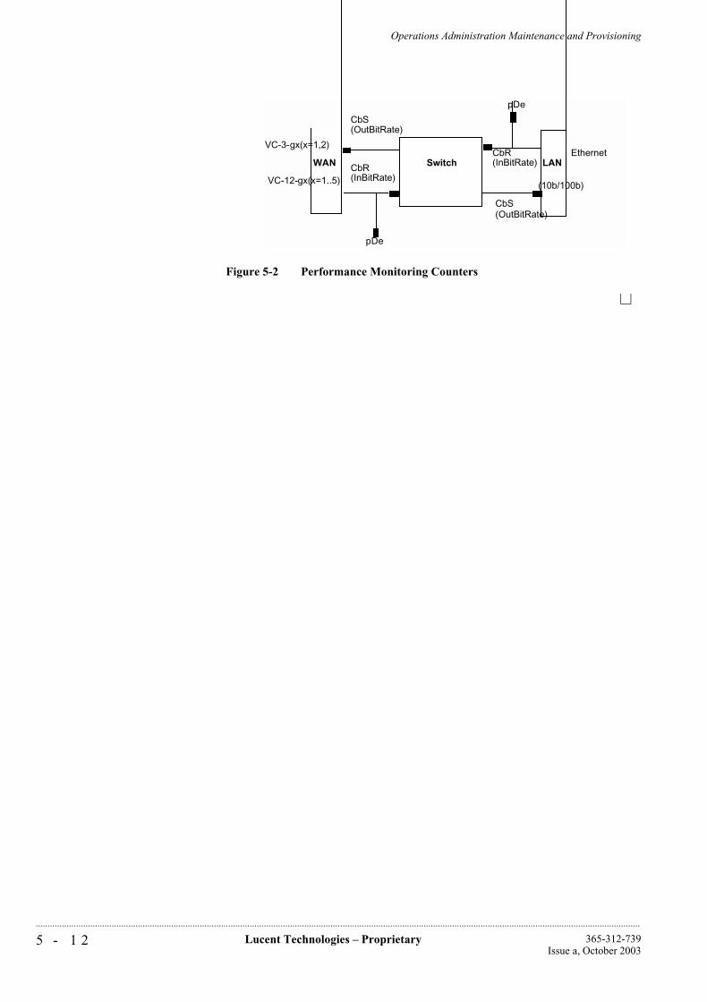
Operations Administration Maintenance and Provisioning
5 - 1 2 Lucent Technologies – Proprietary 365-312-739Issue a, October 2003
..............................................................................................................................................................................................................................................................
Figure 5-2 Performance Monitoring Counters
SwitchWAN LAN
(10b/100b)
VC-3-gx(x=1,2)
VC-12-gx(x=1..5)
Ethernet
CbS(OutBitRate)
CbR(InBitRate)
pDe
pDe
CbR(InBitRate)
CbS(OutBitRate)
Operations Administration Maintenance and Provisioning
5 - 1 3Lucent Technologies – Proprietary365-312-739Issue a, October 2003
..............................................................................................................................................................................................................................................................
...............................................................................................................................................................................................................................................................Maintenance
Maintenance signaling The system maintenance signals notify downstream equipment that a failure has been detected and alarmed by some upstream equipment, and notify upstream equipment to initiate trunk conditioning due to a failure detected downstream.
These alarm signals include alarm indication signals (AIS), far end receive failure (FERF) signals, and unequipped signals (UNEQ).
Alarms and status reports The system provides a report that lists all active alarm and status conditions. This report is made available to the network management system on demand. The identity of the condition is included in the report along with a time stamp indicating when the condition was detected. There is an option to display specified subsets of alarm conditions.
Element Management andremote operations
interfaces
Before it can begin providing services, the Metropolis® ADM (Compact shelf) requires a large amount of provisioning data.
This data is loaded upon installation in non-volatile memories but needs a reliable backup to support repair and maintenance procedures. It is therefore assumed that the equipment is connected to a back-up database either via a local port or via the embedded operations channels.
The Metropolis® ADM (Compact shelf) can be connected to a co-located WaveStar® ITM-SC Management System via the Q-LAN. At station level and besides local or remote network management-facilities, a craft interface terminal (ITM-CIT) can be used to carry out local management functions.
This application is often referred to as “Centralized Alarming and Remote Login”
Fault Detection, Isolationand Reporting
When a fault is detected, the Metropolis® ADM (Compact shelf) employs automatic diagnostic to isolate the failed circuit pack or signal. Failures are reported to local maintenance personnel and operations systems so that repair decisions can be made. If desired, operations system personnel and local maintenance personnel can use the ITM-CIT to gain more detailed information on the fault condition.
A maintenance history report containing past alarms, status, protection switching, and craft or management events is provided, and made available to the network management system on demand. This summary contains time stamp indicating when each condition was detected and cleared, or when a command was entered.
The Metropolis® ADM (Compact shelf) system also automatically and autonomously reports all detected alarm and status conditions through

Operations Administration Maintenance and Provisioning
5 - 1 4 Lucent Technologies – Proprietary 365-312-739Issue a, October 2003
..............................................................................................................................................................................................................................................................
the office alarm relays, user panel, equipment LEDs, and message based operations systems.
Operations Administration Maintenance and Provisioning
5 - 1 5Lucent Technologies – Proprietary365-312-739Issue a, October 2003
..............................................................................................................................................................................................................................................................
...............................................................................................................................................................................................................................................................Reports
Active Alarms and Status The Metropolis® ADM (Compact shelf) provides a report showing all the active alarm and status conditions. The local alarms and status report are displayed automatically on the local ITM-CIT immediately after log in or directly on the network element management system. The report shows the following alarm levels:
PROMPT
DEFERRED
INFO
NO REPORT.
The source address description of the alarm condition (for example controller failure, high-speed signal failure) is included in the report along with the date and time detected. The report also shows whether the alarm condition affects operations. The option to display specified subsets of alarms conditions by severity is also provided.
Reporting of AnalogParameters
Upon user request, the WaveStar® ITM-SC and ITM-CIT can report the values of the laser bias current and optical transmitted power (derived from backface current) of any STM-16/STM-4 core unit in the system. In addition, the value of the optical received power is reported, provided the STM-16/STM-4 port unit in question actually supports this parameter in its hardware.
State An on-demand report displays the equipment and the equipment status.
Equipment report contains:
equipment
location
circuit pack type
version
slot status, (the slot status can be auto or equipped).
Equipment status contains:
equipment
location
circuit pack type
port status (if applicable)
service status (if applicable).
Operations Administration Maintenance and Provisioning
5 - 1 6 Lucent Technologies – Proprietary 365-312-739Issue a, October 2003
..............................................................................................................................................................................................................................................................
Version/equipment List The version/equipment list report is an on-demand report that lists the circuit packs version and the software generic (if applicable). This report also lists all of the circuit packs that are present.
Synchronization Report The synchronization report is an on-demand report that lists the status of the system synchronization. This report lists all the clock parameters that can be interrogated.
Operations Administration Maintenance and Provisioning
5 - 1 7Lucent Technologies – Proprietary365-312-739Issue a, October 2003
..............................................................................................................................................................................................................................................................
...............................................................................................................................................................................................................................................................Provisioning
The system supports many system applications by its provisioning features.
Provisioning parameters are set by software control. These parameters vary from one installation to the next, and a wide range of options or in-service changes can be provisioned locally or remotely with the aid of an ITM-CIT or WaveStar® ITM-SC.
Default provisioning Installation provisioning is minimized with carefully chosen default values/parameters defined and maintained in the System Controller, and a simple command can be given to restore all default values. All provisioning data is stored in non-volatile memory to prevent data loss during power failures.
Automatic provisioning onreplacement
Replacement of a faulty circuit pack is simplified by the automatic provisioning of the original values. The system controller maintains a provisioning map of the entire subrack so when a transmission or synchronization circuit pack is replaced, the system controller automatically downloads values to the new circuit pack and initiates testing of the new circuit pack. If the system controller itself is replaced, provisioning data from a back-up database mounted in the WaveStar®
ITM-SC, is automatically downloaded to the new System Controller’s non-volatile memory assumed it is empty.
If the controller database is not empty but valid, the choice is offered to download or upload.
Provisioning reports The provisioning report, which is made available to the WaveStar® ITM-SC on demand, contains the current values of all electronically provisionable parameters.

Operations Administration Maintenance and Provisioning
5 - 1 8 Lucent Technologies – Proprietary 365-312-739Issue a, October 2003
..............................................................................................................................................................................................................................................................
6 - 1Lucent Technologies – Proprietary365-312-739Issue a, October 2003
..............................................................................................................................................................................................................................................................
6 Cross-Product Interworking
...............................................................................................................................................................................................................................................................Overview
This chapter contains a brief description of the Lucent Technologies SDH systems that interwork with the Metropolis® ADM (Compact shelf) in today’s telecommunications networks. The application of the Metropolis® ADM (Compact shelf) is briefly described in Chapter 3, Applications.
For more detailed information, reference is made to the Application and Planning Guide of the system concerned.
Cross-Product Interworking
6 - 2 Lucent Technologies – Proprietary 365-312-739Issue a, October 2003
..............................................................................................................................................................................................................................................................
...............................................................................................................................................................................................................................................................Lucent Technologies SDH Product Family
Products Lucent Technologies SDH Product family is well suited for PDH, SDH and Ethernet network applications serving line rates from 1.5 Mbit/s to
400 Gbit/s.
Lucent Technologies designed the following members of the SDH product family which can interwork with the Metropolis® ADM (Compact shelf):
WaveStar® OLS 80G (via OTUs)
WaveStar® OLS 1.6T (formerly know as OLS 400G) (via OTUs)
WaveStar® BWM
Metropolis® ADM
WaveStar® DACS 4/4/1
WaveStar® ADM 4/1 SDH multiplex system
Metropolis® AM
Metropolis® AMS
SDH Radio Systems
ISM, current generation SDH multiplexers
SLM, current generation SDH line system
PHASE, current generation SDH line/multiplex systems
WaveStar® EOW
WaveStar® ITM-SC Controller, an Element Management system for the SDH multiplexer and transport system
Navis® Optical NMS, a Network Management system for transport networks.
From a network point of view, SDH is the answer to the rapidly changing demand for services on the one hand, and on the other the increasing cost of implementing these services in switching equipment. The latter means that the switching equipment has to provide for larger and larger areas to keep cost per line at an economical level. This causes an increase in the deployment of transmission systems because the average distance between subscribers and the central exchange (and also the distance between exchanges) increases. The cost penalty for extra transmission equipment was relatively low thanks to new developments in transmission technology (e.g. optical fiber).
Cross-Product Interworking
6 - 3Lucent Technologies – Proprietary365-312-739Issue a, October 2003
..............................................................................................................................................................................................................................................................
The existing (plesiochronous digital hierarchy - PDH) transmission network is structured with a fixed multiplex architecture (2/8, 8/34, 34/140 Mbit/s). Digital distribution frames are installed between the multiplex equipment where the signal cabling is connected. The routing of some of the data streams is established with these connections. The other streams are demultiplexed to 2 Mbit/s and connected to the exchange. Making changes in such a transmission network requires manual action and accurate administration. So flexibility is not optimal and operating costs increase when the demand is changing continuously.
Cross-Product Interworking
6 - 4 Lucent Technologies – Proprietary 365-312-739Issue a, October 2003
..............................................................................................................................................................................................................................................................
...............................................................................................................................................................................................................................................................Network systems
WaveStar® BWM The WaveStar® BandWidth Manager is the best path to convergence for layered bandwidth management in one network element. The WaveStar® BandWidth Manager integrates all access and transport rings within a network and efficiently manages bandwidth among these rings via modular, scalable synchronous transport mode (STM), asynchronous transfer mode (ATM), and internet protocol (IP) fabrics. The three switching fabrics are surrounded by a common input/output and managed by a common system controller.
Features:
Operational savings
Increased reliability
Integrated optical line systems
Future proof - scalable networks
Substantial first equipment cost savings
WaveStar® DACS 4/4/1 The WaveStar® DACS 4/4/1 is the latest cross-connect system from Lucent Technologies. It is a large-capacity SDH 4/4/3/3/1 cross-connect system. It can operate in any of the following modes:
Broadband (4/4) mode
Wideband (4/3/1) mode
Broadband/Wideband (4/4/3/1) mode.
In all three modes, the WaveStar® DACS 4/4/1 has a maximum capacity of 512 STM-1 equivalents. On element level the WaveStar® DACS 4/4/1 is managed by the WaveStar® ITM-SC. Furthermore, Lucent’s proven multivendor world-class network manager, Navis® Optical NMS, integrates WaveStar® DACS 4/4/1 into Lucent’s complete SDH network offering.
Based on Lucent’s experience with large SDH networks, the WaveStar® DACS 4/4/1 provides the following benefits:
Large capacity cross-connect that is cost effective in small and large configurations
Highly reliable cross-connect in which all service affecting components are either triply or doubly protected against equipment failure
Cross-Product Interworking
6 - 5Lucent Technologies – Proprietary365-312-739Issue a, October 2003
..............................................................................................................................................................................................................................................................
Broadband (4/4) restoration vehicle that increases broadband network reliability when combined with the Navis® Optical NMS network manager. This fully EMC and ESD-compliant product cross-connects AU-4s and AU-3s with a maximum transit delay of 15 microseconds.
Wideband (4/1) restoration vehicle that increases wide band network reliability when combined with the Navis® Optical NMS network manager. When operating in 4/1 mode, the WaveStar® DACS 4/4/1 provides the same basic feature set as the former DACS VI with a size of up to 512 STM-1 equivalents. However, WaveStar® DACS 4/4/1 is primarily designed for SDH to make it more suitable as a network restoration and grooming vehicle. The WaveStar® DACS 4/4/1 and DACS VI can be used in the same network, and both systems can be managed by the same network manager, Navis® Optical NMS.
Wideband grooming capability that allows the customer to improve network efficiency by optimizing bandwidth usage.
4/4/1 cross-connect that provides fast provisioning of wide band and broadband services as well as other network provisioning. WaveStar® DACS 4/4/1 is an excellent choice for applications in the trunk/junction part of the network. When operating in 4/4/1 mode, the WaveStar® DACS 4/4/ 1 combines the capabilities of a 4/4 cross-connect and a 4/1 cross-connect. Having the 4/4/1 functionality contained in a single cost-effective and flexible cross-connect not only results in lower equipment costs but also improves network manageability, especially when used in combination with Navis® Optical NMS.
WaveStar® DACS 4/4/1 and Metropolis® ADM (Compact shelf) can be interconnected via STM-1/e, STM-1o, STM-4o and STM-16o interfaces.
Metropolis® ADM 4/1 The WaveStar® ADM 4/1 system has as the main application to give access to an SDH network. It can work in both synchronous and asynchronous environments. Further, it contains an advanced pointer processing feature to eliminate phase shifts so it can be used for wireless base stations that need to be in perfect synchronization with the master station. The system can be used as a terminal multiplexer / dual terminal multiplexer (126 x 2 Mbit/s) or as an add/ drop multiplexer for up to 63 x 2 Mbit/s or a Hub Multiplexer for up to 5 STM-1 interfaces. It can be used in a large variety of network types such as rings, stars and strings. It has advanced protection mechanisms such as card protection, MSP, path
Cross-Product Interworking
6 - 6 Lucent Technologies – Proprietary 365-312-739Issue a, October 2003
..............................................................................................................................................................................................................................................................
protection and SNCP. Synchronization could come from various sources such as from 2 Mbit/s tributary, STM-1 aggregate incoming signal, STM-1 tributary incoming signal or an external 2 MHz clock.
The WaveStar® ADM 4/1 consists of a shelf with 1 supervision slot and 6 flexible slots that can contain units with one or more of the following functionalities: 16 x 2 Mbit/s tributaries, 32 x 2 Mbit/s tributaries, 34 Mbit/s or 45 Mbit/s tributary, STM-1 optical or electrical line interface, STM-4 optical line interface, transfer for the add/ drop function. All boards have on-board power converters. In case of card protection, 2 Mbit/s switches are mounted on the connecting field of the shelf.
The WaveStar® ADM 4/1 is controlled by and managed by Lucent Technologies Navis® Optical Management Solution for network and element level management.
Metropolis® AMS The Metropolis® AMS is a compact and cost-effective STM-1 multiplexer designed to be installed at the customer’s premises or street cabinets for fiber-to-the-business, fiber-to-the curb and fiber-to-the office applications. The Metropolis® AMS supports either add-drop or terminal multiplexer applications. Its’ space-efficient design allows for wall-mounting or rack mounting in non-environmentally controlled locations. The Metropolis® AMS supports additional options (16) 2 Mbit/s E1 or (16) 1.5 Mbit/s ports or (2) 34 Mbit E3 ports. The Metropolis® AMS measures 430 x 200 x 280 mm (H x D x W) and provides for a wall-mounted or rack-mounted unit.
Metropolis® AM The Metropolis® AM is the successor of the Metropolis® AMS. The Metropolis® AM is a compact and cost-effective STM-1 and STM-4 multiplexer designed to be installed at the customer’s premises or street cabinets. It supports STM-1 and STM-4 optical line interface with 1+1 MSP or SNC protection. The main tributary interface board can support 16 x E1, and there are several optional cards that can be chosen:
16 x E1
16 x DS1
2 x E3
2 x DS3
4 x X.21 (2Mbit/s)
4 x 10/100BaseT Ethernet
12 x SHDSL
SDH Radio systems To enhance the applicability of SDH and to provide full flexibility in network design, the range of Lucent Technologies SDH products includes a family of SDH STM-1 digital radio systems.
Cross-Product Interworking
6 - 7Lucent Technologies – Proprietary365-312-739Issue a, October 2003
..............................................................................................................................................................................................................................................................
Digital radio systems are the preferred solution for otherwise inaccessible areas due to terrain or right-of-way limitations, as well as for back-up configurations.
The SDH radio equipment is designed to operate in frequency bands with 30, 40 or 55 MHz channel spacing, as defined in the relevant ITU-R Recommendations. Each radio channel can carry one STM-1 signal that can be utilized in several ways.
The SDH radio equipment provides for transmission of multiple STM-1 signals, realized either as protected or as unprotected configurations. Mapping has been integrated for PDH applications, making a 140 Mbit/s PDH interface available.
Changeover between 140 Mbit/s PDH and 155 Mbit/s SDH is easily implemented by the simple setting of switches. The 155 Mbit/s can support the DCC channels for communicating with other equipment after radio transmission.
Supervisory system: The SDH Radio system can be provided with a Q adapter for connection to the Lucent Technologies element manager (WaveStar® ITM-SC). The inclusion of the radio system in the Lucent Technologies SDH product portfolio offers supervision of the complete network by the same element manager.
ISM The ISM Intelligent Synchronous Multiplexer is a network multiplexer primarily designed to flexibly multiplex plesiochronous tributaries into 155 Mbit/s (STM-1) or 622 Mbit/s (STM-4) aggregate signals, which are transmitted through single mode optical fibers.
The ISM system consists of one platform. A platform is a family of equipment and software configurations designed to support a particular set of applications. These applications include:
ISM-1 Terminal
ISM-1 Fibers Add/Drop Terminal
ISM-4 Terminal
ISM-4 Fibers Add/Drop Terminal.
SLM The SLM is a high-capacity optical line multiplexer that transmits digitally encoded information through single-mode optical fibers at STM-16 level. The SLM provides for 16 times STM-1 (electrical or optical) and/or CEPT-4 (140 Mbit/s, electrical) multiplex and transport capacity.
The SLM consists of three platforms. A platform is a family of equipment and software configurations designed to support a particular set of applications:
End terminal regenerators
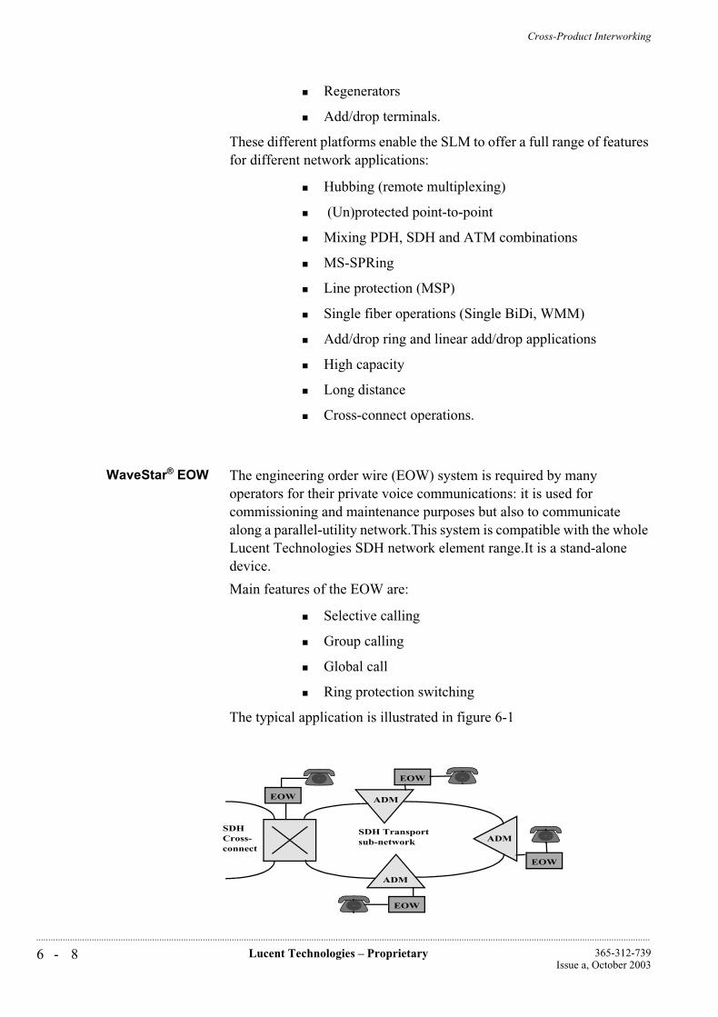
Cross-Product Interworking
6 - 8 Lucent Technologies – Proprietary 365-312-739Issue a, October 2003
..............................................................................................................................................................................................................................................................
Regenerators
Add/drop terminals.
These different platforms enable the SLM to offer a full range of features for different network applications:
Hubbing (remote multiplexing)
(Un)protected point-to-point
Mixing PDH, SDH and ATM combinations
MS-SPRing
Line protection (MSP)
Single fiber operations (Single BiDi, WMM)
Add/drop ring and linear add/drop applications
High capacity
Long distance
Cross-connect operations.
WaveStar® EOW The engineering order wire (EOW) system is required by many operators for their private voice communications: it is used for commissioning and maintenance purposes but also to communicate along a parallel-utility network.This system is compatible with the whole Lucent Technologies SDH network element range.It is a stand-alone device.
Main features of the EOW are:
Selective calling
Group calling
Global call
Ring protection switching
The typical application is illustrated in figure 6-1
ADM
ADM
ADM
EOW
EOW
EOW
SDH Transportsub-network
SDHCross-connect
EOW

Cross-Product Interworking
6 - 9Lucent Technologies – Proprietary365-312-739Issue a, October 2003
..............................................................................................................................................................................................................................................................
Figure 6-1 WaveStar® EOW in SDH ring
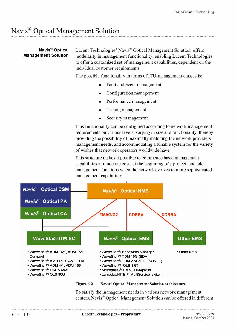
Cross-Product Interworking
6 - 1 0 Lucent Technologies – Proprietary 365-312-739Issue a, October 2003
..............................................................................................................................................................................................................................................................
...............................................................................................................................................................................................................................................................Navis® Optical Management Solution
Navis® OpticalManagement Solution
Lucent Technologies’ Navis® Optical Management Solution, offers modularity in management functionality, enabling Lucent Technologies to offer a customized set of management capabilities, dependent on the individual customer requirements.
The possible functionality in terms of ITU-management classes is:
Fault and event management
Configuration management
Performance management
Testing management
Security management.
This functionality can be configured according to network management requirements on various levels, varying in size and functionality, thereby providing the possibility of maximally matching the network providers management needs, and accommodating a tunable system for the variety of wishes that network operators worldwide have.
This structure makes it possible to commence basic management capabilities at moderate costs at the beginning of a project, and add management functions when the network evolves to more sophisticated management capabilities.
Figure 6-2 Navis® Optical Management Solution architecture
To satisfy the management needs in various network management centers, Navis® Optical Management Solution can be offered in different
CORBA CORBA
Navis® Optical NMS
Navis® Optical EMSWaveStar® ITM-SC Other EMS
Navis® Optical PA
Navis® Optical CA
Navis® Optical CSM
• WaveStar ® Bandwidth Manager• WaveStar ® TDM 10G (SDH)• WaveStar ® TDM 2.5G/10G (SONET)• WaveStar ® OLS 1.6T• Metropolis ® DMX, DMXpress• LambdaUNITE ® MultiService switch
• WaveStar ® ADM 16/1, ADM 16/1Compact
• WaveStar ® AM 1 Plus, AM 1, TM 1• WaveStar ® ADM 4/1, ADM 155• WaveStar ® DACS 4/4/1• WaveStar ® OLS 80G
• Other NE’s
TMAG/G2 CORBA CORBA
Navis® Optical NMS
Navis® Optical EMSWaveStar® ITM-SC Other EMS
Navis® Optical PA
Navis® Optical CA
Navis® Optical CSM
• WaveStar ® Bandwidth Manager• WaveStar ® TDM 10G (SDH)• WaveStar ® TDM 2.5G/10G (SONET)• WaveStar ® OLS 1.6T• Metropolis ® DMX, DMXpress• LambdaUNITE ® MultiService switch
• WaveStar ® ADM 16/1, ADM 16/1Compact
• WaveStar ® AM 1 Plus, AM 1, TM 1• WaveStar ® ADM 4/1, ADM 155• WaveStar ® DACS 4/4/1• WaveStar ® OLS 80G
• Other NE’s
TMAG/G2
Cross-Product Interworking
6 - 1 1Lucent Technologies – Proprietary365-312-739Issue a, October 2003
..............................................................................................................................................................................................................................................................
configurations, depending on the needs in the particular management centers, offering management functionality in a tailored fashion.
Extension of capabilities of Navis® Optical Management Solution with another management module, or addition of functionality within a module is realized by upgrading software, and might involve additional hardware.
Navis® Optical Management Solution is compliant with the ITU architecture and recommendations mentioned in G.784 and provides standardized open Q-type interfaces.
Based on the required network management functions and used network elements, different modules are used to form the Navis® Optical Management Solution:
WaveStar® ITM-SC, a network element management system for the WaveStar® TM 1, WaveStar® AM 1,WaveStar® AM 1 Plus, Metropolis® ADM (Compact shelf), Metropolis® ADM, WaveStar®DACS 4/4/1, ISM/SLM and SDH radio.
Navis® Optical NMS, a network management system for transport networks.
WaveStar® ITM-SC The element management system WaveStar® ITM-SC was developed to aid in the operation of SDH networks. The WaveStar® ITM-SC is a centralized management system for use with SDH network elements, which are interconnected either by optical or metallic lines operating at STM-1 (155 Mbit/s), STM-4 (622 Mbit/s) or STM-16 (2.5 Gbit/s). The management functions in the WaveStar® ITM-SC include both mediation and operation (OS) functions. It is also possible to relocate the OS functions to a physically separate system, leaving the WaveStar®
ITM-SC to perform the role of mediator. In the absence of an OS, management can be performed using the network element local interface (ELI), which employs a large set of MML commands and a remote access feature to enable a user at one network element to perform and control and monitoring functions at any other connected network element. The Q2/Q3 model chosen for the WaveStar® ITM-SC is consistent with current thinking within the international standards community, in which Lucent Technologies participates actively. Low-level filtering and message processing is performed and a higher level Q3 interface is provided.
Navis® Optical NMS The Navis® Optical NMS provides centralized control and a comprehensive set of features and functions for the management of SDH and DWDM networks. The Navis® Optical NMS is multi-vendor in nature and is able to support both Lucent Technologies and multi-vendor networks. The Navis® Optical NMS module interfaces with the Navis® Optical EMS and WaveStar® ITM-SC (Element Management) modules
Cross-Product Interworking
6 - 1 2 Lucent Technologies – Proprietary 365-312-739Issue a, October 2003
..............................................................................................................................................................................................................................................................
(for DWDM and SDH). The value of Navis® Optical NMS lies in its ability to provide state-of-the-art network management capabilities that enable the service providers to differentiate from their competitors and provide them with a new source of revenue.
In particular Navis® Optical NMS provides:
End to end SDH Circuit Provisioning (auto and semi automatic and manual routing)
End to end DWDM Optical Channel Provisioning (auto and semi automatic and manual routing)
SDH Circuit Fault and Performance Management
Optical Channel Fault and Performance Management
JAVA based Graphical User Interface
Northbound CORBA Interface to Service Management and Inter-domain Management Systems
Scalable architecture to support 15,000 Network Element equivalents
7 - 1Lucent Technologies – Proprietary365-312-739Issue a, October 2003
..............................................................................................................................................................................................................................................................
7 Physical design
...............................................................................................................................................................................................................................................................Introduction
The Metropolis® ADM (Compact shelf) is one of the Lucent Technologies’ third generation of SDH equipment. In particular in the mechanical design of the system, the overall system requirements of compact design and flexibility where given special attention.
The design of the Metropolis® ADM (Compact shelf) is based on an ETSI 600 x 300-mm footprint and operates without fans.
Another great advantage is that the equipment is front accessed, all the connectors and boards are located at the front. An 600 x 600-mm rack supports back-to-back configurations, allowing up to 6 Metropolis® ADM (Compact shelf) systems in an 600 x 600-mm footprint.
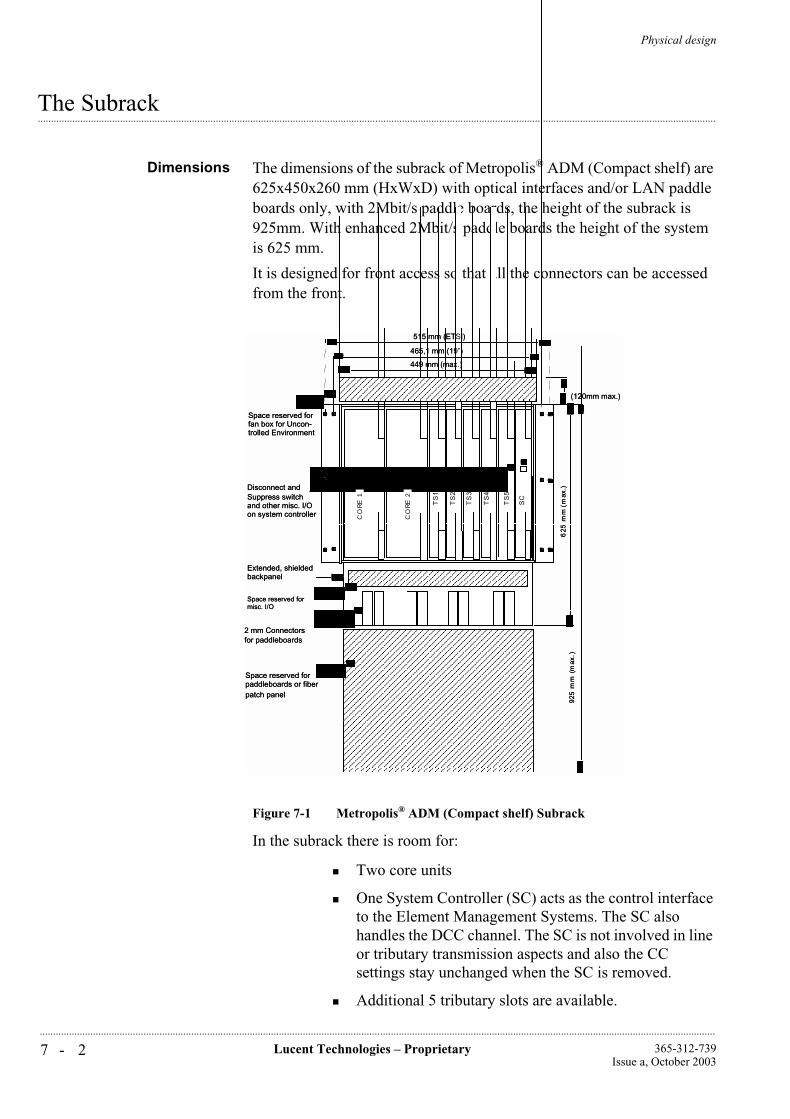
Physical design
7 - 2 Lucent Technologies – Proprietary 365-312-739Issue a, October 2003
..............................................................................................................................................................................................................................................................
...............................................................................................................................................................................................................................................................The Subrack
Dimensions The dimensions of the subrack of Metropolis® ADM (Compact shelf) are 625x450x260 mm (HxWxD) with optical interfaces and/or LAN paddle boards only, with 2Mbit/s paddle boards, the height of the subrack is 925mm. With enhanced 2Mbit/s paddle boards the height of the system is 625 mm.
It is designed for front access so that all the connectors can be accessed from the front.
Figure 7-1 Metropolis® ADM (Compact shelf) Subrack
In the subrack there is room for:
Two core units
One System Controller (SC) acts as the control interface to the Element Management Systems. The SC also handles the DCC channel. The SC is not involved in line or tributary transmission aspects and also the CC settings stay unchanged when the SC is removed.
Additional 5 tributary slots are available.
Space reserved for paddleboards or fiber
2 mm Connectors for paddleboards
Disconnect and
SI-
16C
TS
5
TS
2
TS
3
TS
4
Space reserved for
SC
TS
1
misc. I/O
Extended, shieldedbackpanel
patch panel
925
mm
(m
ax.)
Space reserved for fan box for Uncon-trolled Environment
449 mm (max.)
465,1 mm (19”)
and other misc. I/O on system controller
625
mm
(m
ax.)
(120mm max.)
515 mm (ETSI)
Suppress switch
SI-
16C
CO
RE 1
CO
RE 2
Physical design
7 - 3Lucent Technologies – Proprietary365-312-739Issue a, October 2003
..............................................................................................................................................................................................................................................................
The subrack is closed by metal face and rear plates with metal spring contacts.
The subrack with metal cover plates forms the EMC boundary of the Metropolis® ADM (Compact shelf).
For ESD precautions, a person installing equipment must carry a bracelet. On front of the Lucent Technologies racks an earth contact is provided to connect the bracelet to.
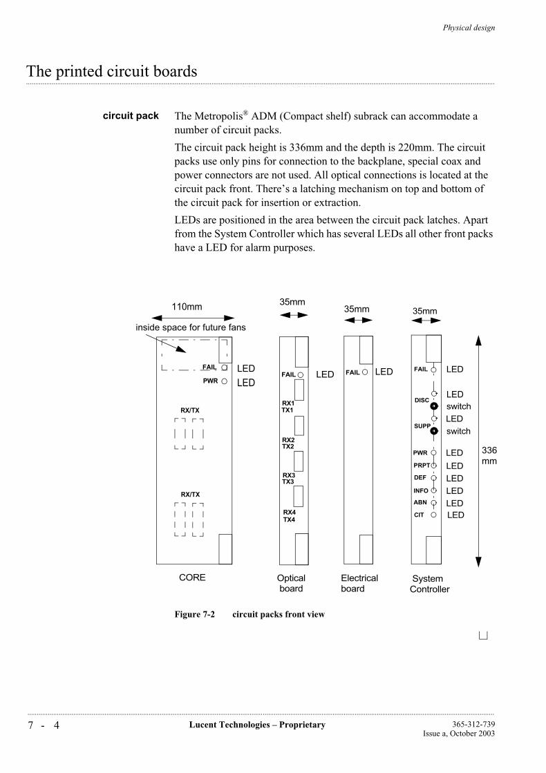
Physical design
7 - 4 Lucent Technologies – Proprietary 365-312-739Issue a, October 2003
..............................................................................................................................................................................................................................................................
...............................................................................................................................................................................................................................................................The printed circuit boards
circuit pack The Metropolis® ADM (Compact shelf) subrack can accommodate a number of circuit packs.
The circuit pack height is 336mm and the depth is 220mm. The circuit packs use only pins for connection to the backplane, special coax and power connectors are not used. All optical connections is located at the circuit pack front. There’s a latching mechanism on top and bottom of the circuit pack for insertion or extraction.
LEDs are positioned in the area between the circuit pack latches. Apart from the System Controller which has several LEDs all other front packs have a LED for alarm purposes.
Figure 7-2 circuit packs front view
35mm
LED
Optical
FAIL
RX1TX1
RX2TX2
RX3TX3
RX4TX4
35mm
LEDFAIL
LED
LEDLEDLEDLED
LEDswitchLEDswitch
LED
LED
35mm
FAIL
DISC
SUPP
PWR
PRPT
DEF
INFO
ABN
CIT
110mm
LED
LED
RX/TX
FAIL
PWR
board
336 mm
Electrical board
SystemController
CORE
inside space for future fans
RX/TX
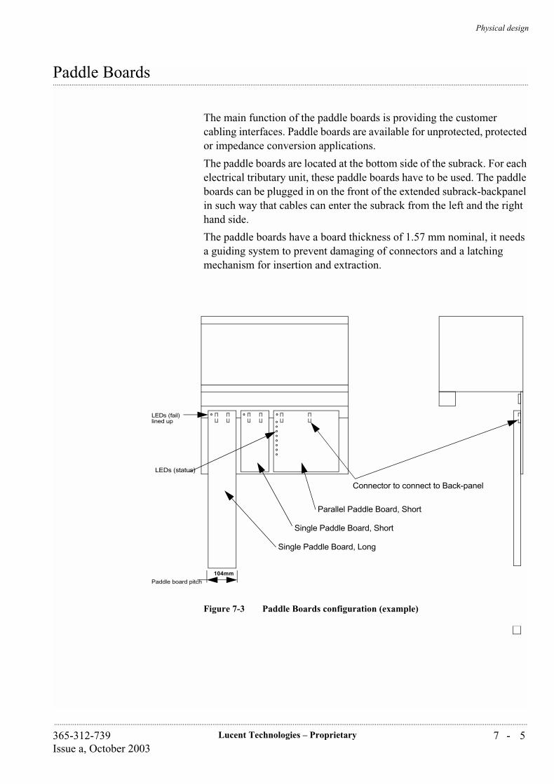
Physical design
7 - 5Lucent Technologies – Proprietary365-312-739Issue a, October 2003
..............................................................................................................................................................................................................................................................
...............................................................................................................................................................................................................................................................Paddle Boards
The main function of the paddle boards is providing the customer cabling interfaces. Paddle boards are available for unprotected, protected or impedance conversion applications.
The paddle boards are located at the bottom side of the subrack. For each electrical tributary unit, these paddle boards have to be used. The paddle boards can be plugged in on the front of the extended subrack-backpanel in such way that cables can enter the subrack from the left and the right hand side.
The paddle boards have a board thickness of 1.57 mm nominal, it needs a guiding system to prevent damaging of connectors and a latching mechanism for insertion and extraction.
Figure 7-3 Paddle Boards configuration (example)
104mm
Parallel Paddle Board, Short
Single Paddle Board, Short
Single Paddle Board, Long
LEDs (fail)
Paddle board pitch
Connector to connect to Back-panel
lined up
LEDs (status)
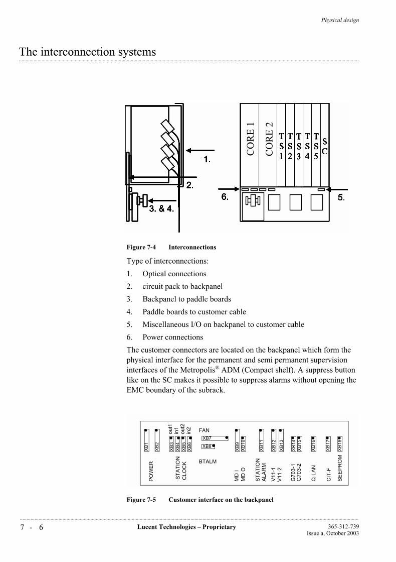
Physical design
7 - 6 Lucent Technologies – Proprietary 365-312-739Issue a, October 2003
..............................................................................................................................................................................................................................................................
...............................................................................................................................................................................................................................................................The interconnection systems
Figure 7-4 Interconnections
Type of interconnections:
1. Optical connections
2. circuit pack to backpanel
3. Backpanel to paddle boards
4. Paddle boards to customer cable
5. Miscellaneous I/O on backpanel to customer cable
6. Power connections
The customer connectors are located on the backpanel which form the physical interface for the permanent and semi permanent supervision interfaces of the Metropolis® ADM (Compact shelf). A suppress button like on the SC makes it possible to suppress alarms without opening the EMC boundary of the subrack.
Figure 7-5 Customer interface on the backpanel
3. & 4.
1.
2.
SI-16C
SI-16C
TS1
TS2
TS3
TS4
TS5
SC
6. 5.
CO
RE
CO
RE
3. & 4.
1.
2.
SI-16C
SI-16C
TS1
TS2
TS3
TS4
TS5
SC
6. 5.
CO
RE
1
CO
RE
2
3. & 4.
1.
2.
SI-16C
SI-16C
TS1
TS2
TS3
TS4
TS5
SC
6. 5.3. & 4.
1.
2.
SI-16C
SI-16C
TS1
TS2
TS3
TS4
TS5
SC
6. 5.
CO
RE
CO
RE
3. & 4.
1.
2.
SI-16C
SI-16C
TS1
TS2
TS3
TS4
TS5
SC
6. 5.3. & 4.
1.
2.
SI-16C
SI-16C
TS1
TS2
TS3
TS4
TS5
SC
6. 5.
CO
RE
1
CO
RE
2
PO
WE
R
ST
AT
ION
CLO
CK
G70
3-1
V11
-1
BTALM
MD
I
Q-L
AN
CIT
-F
FAN
ST
AT
ION
SE
EP
RO
M
XB
3X
B4
XB
5X
B6
XB
1
XB
2
XB7
XB8
XB
9X
B10
XB
11
XB
12
XB
13
XB
17
XB
16
XB
14X
B15
XB
18
ALA
RM
out1
in1
out2
in2
MD
O
V11
-2
G70
3-2
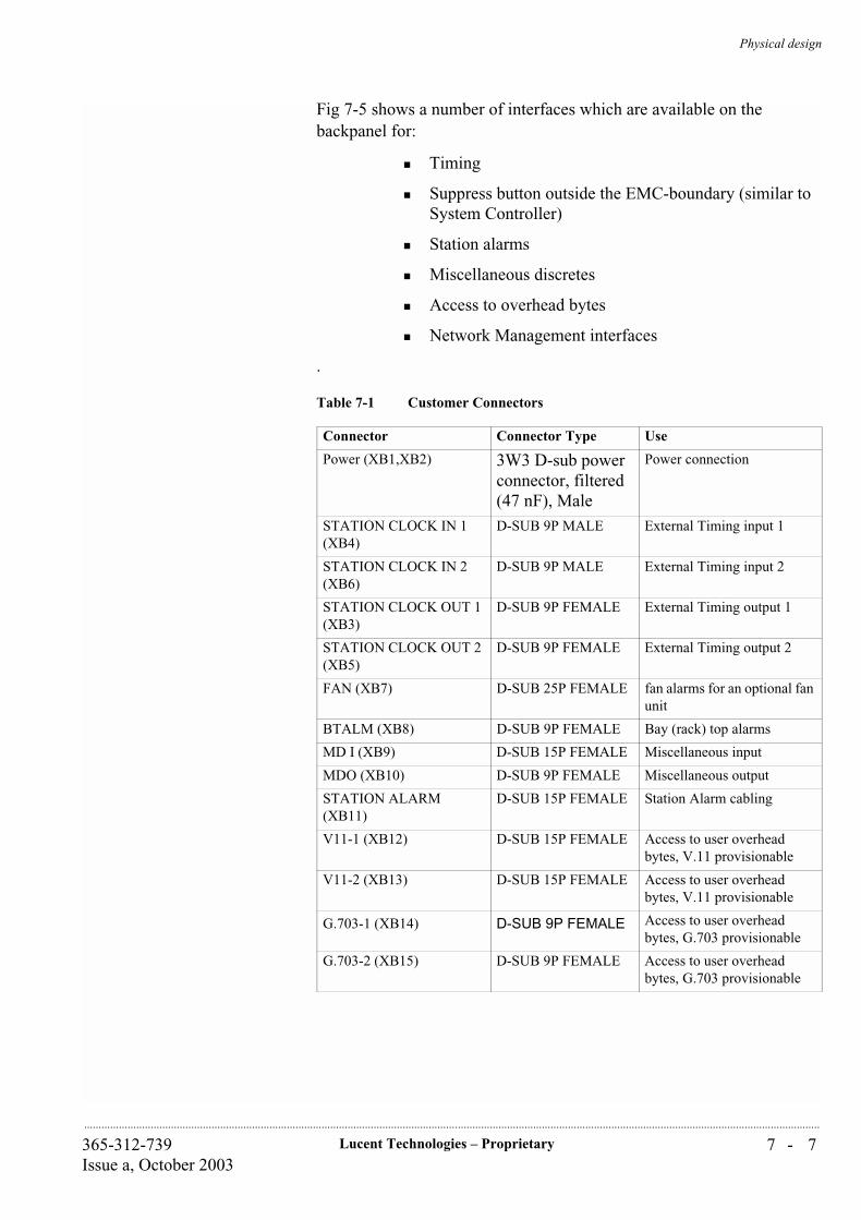
Physical design
7 - 7Lucent Technologies – Proprietary365-312-739Issue a, October 2003
..............................................................................................................................................................................................................................................................
Fig 7-5 shows a number of interfaces which are available on the backpanel for:
Timing
Suppress button outside the EMC-boundary (similar to System Controller)
Station alarms
Miscellaneous discretes
Access to overhead bytes
Network Management interfaces
.
Table 7-1 Customer Connectors
Connector Connector Type Use
Power (XB1,XB2) 3W3 D-sub power connector, filtered (47 nF), Male
Power connection
STATION CLOCK IN 1 (XB4)
D-SUB 9P MALE External Timing input 1
STATION CLOCK IN 2 (XB6)
D-SUB 9P MALE External Timing input 2
STATION CLOCK OUT 1 (XB3)
D-SUB 9P FEMALE External Timing output 1
STATION CLOCK OUT 2 (XB5)
D-SUB 9P FEMALE External Timing output 2
FAN (XB7) D-SUB 25P FEMALE fan alarms for an optional fan unit
BTALM (XB8) D-SUB 9P FEMALE Bay (rack) top alarms
MD I (XB9) D-SUB 15P FEMALE Miscellaneous input
MDO (XB10) D-SUB 9P FEMALE Miscellaneous output
STATION ALARM (XB11)
D-SUB 15P FEMALE Station Alarm cabling
V11-1 (XB12) D-SUB 15P FEMALE Access to user overhead bytes, V.11 provisionable
V11-2 (XB13) D-SUB 15P FEMALE Access to user overhead bytes, V.11 provisionable
G.703-1 (XB14) D-SUB 9P FEMALE Access to user overhead bytes, G.703 provisionable
G.703-2 (XB15) D-SUB 9P FEMALE Access to user overhead bytes, G.703 provisionable
Physical design
7 - 8 Lucent Technologies – Proprietary 365-312-739Issue a, October 2003
..............................................................................................................................................................................................................................................................
7I
Face plates for front accessunits
It is possible to equip the front access units with face plate. These face plates are designed in such, that mounting is also possible on already deployed units. In this way it is possible to create a uniform front sight of the Metropolis® ADM (Compact shelf) with the front subrack cover removed.
The face plates are fully EMC and ESD safe.
For empty places dummy units are available in different sizes.
ETSI compliant racks600x300 mm
Lucent Technologies can provide a number of dedicated ETSI compliant racks for housing of the Metropolis® ADM (Compact shelf) subracks.
In an 600mm deep rack, back to back mounting is possible, to double the number of systems per rack.
There are limits in cabling flexibility related to the rack size. In general, the higher the rack the more flexible the cabling philosophy.
Each rack has two alarm lamps on front and back side for prompt and deferred maintenance alarms. The equivalent lamps of front and backside are set in parallel.
The four ETSI racks have standard improved fiber management. This means that fibers in the rack are housed in a tube which separates them from the electrical cables. So the fiber cables that are more vulnerable, are better protected and bow radii are also better maintained.
The ETSI racks have got one fiber guide standard mounted over the full working length of the rack.
Q-LAN (XB16) D-SUB 9P FEMALE ITM-CIT connection
CIT-F D-SUB 9P FEMALE ITM SC connection, (Twisted Pair Ethernet)
SEEPROM D-SUB 9P FEMALE used for the eeprom (backplane inventory) which comes with each subrack
Table 7-1 Customer Connectors
Table 7-2 Available ETSI compliant racks
Rack Type Remarks
ETSI Rack Frame 2200x600x300 mm (HxWxD) assembled
ETSI Rack Frame 2200x600x300 mm (HxWxD) as a kit
ETSI Rack Frame 2600x600x300 mm (HxWxD) assembled
ETSI Rack Frame 2600x600x300 mm (HxWxD) as a kit
Physical design
7 - 9Lucent Technologies – Proprietary365-312-739Issue a, October 2003
..............................................................................................................................................................................................................................................................
For distribution of the power within the racks towards the subrack, a Power Distribution panel is needed. The panel has a function to secure the power network, by using automatic fuses, included as well.
Connector The electrical connectors are located on the paddle board, the front accessed connectors make the implementation and maintenance easier and quicker. All the optical interfaces are located on the front side of the circuit packs.
7
Table 7-3 Overview of interface types, cables and connector
Interface type Cable typeConnector type on connector plate
Number of cables/ connectors per slot
1.5/2Mbit/s COAX 25 pins D-sub 16 8-fold
1.5/2Mbit/s UTP 25 pins D-sub 16 8-fold
1.5/2Mbit/s STP 25 pins D-sub 16 8-fold
34/45 Mbit/s COAX coax 1.6/5.6 connector, female
24 coax
STM-1e COAX coax 1.6/5.6 connector, female
8 coax
10/100BASE-T CAT5 RJ45 8
1000BASE-X OPTICAL LC 4
Physical design
7 - 1 0 Lucent Technologies – Proprietary 365-312-739Issue a, October 2003
..............................................................................................................................................................................................................................................................
...............................................................................................................................................................................................................................................................Cabling
Metropolis® ADM (Compact shelf) requires a number of cable types to connect the system. The cable can be:
- 1.5/2MBit/s 75 ohm 8 fold coaxial cable 75 ohm *
- 1.5/2MBit/s 120 ohm 8 fold shielded twisted pair 120 ohm *
- 1.5/2MBit/s 120 ohm 8 fold Un-shielded twisted pair 120 ohm *
- 34/45MBit/s single coaxial cable 75 ohm
- 155MBit/s single coaxial cable 75 ohm
- LAN4 twisted pair CAT5 cable *
- Misc. I/Oseveral types of wires *
- power 4mm2 power wires
- 1000BASE-X Optical cables
- STM1o Optical cables
- STM4o Optical cables
- STM-16o Optical cables
Remark: * to fulfil the EMC requirements all these cables should have an overall shield.
Optical cables are separated from the electrical cables and are guided in fibre ducts. The preferred installation sequence is by top entry (when the cables enter the rack on the top): From the bottom subrack to the sub-rack in top, and by bottom entry: from the sub-rack in top to the lowest sub-rack.
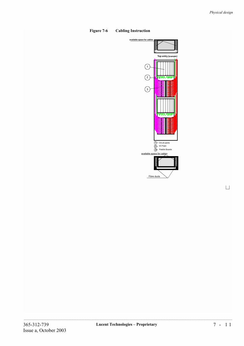
Physical design
7 - 1 1Lucent Technologies – Proprietary365-312-739Issue a, October 2003
..............................................................................................................................................................................................................................................................
Figure 7-6 Cabling Instruction
123
Circuit packs
I/O Field
Paddle Boards
1
2
3
available space for cables
Top entry (example)
available space for cables
Fibre ducts

Physical design
7 - 1 2 Lucent Technologies – Proprietary 365-312-739Issue a, October 2003
..............................................................................................................................................................................................................................................................

8 - 1Lucent Technologies – Proprietary365-312-739Issue a, October 2003
..............................................................................................................................................................................................................................................................
8 System Planning and Engineering
...............................................................................................................................................................................................................................................................Overview
This chapter summarizes the descriptive information used for system planning. It describes the basic engineering rules for the Metropolis® ADM (Compact shelf).

System Planning and Engineering
8 - 2 Lucent Technologies – Proprietary 365-312-739Issue a, October 2003
..............................................................................................................................................................................................................................................................
...............................................................................................................................................................................................................................................................Network Planning
Introduction There are a number of issues to consider when planning a network. Projected customer requirements determine the network topology and traffic capacities needed, both initially and in the future. These considerations drive, in their turn, the equipment planning and physical installation. In addition synchronization and management need to be planned.
The building constructed or selected to serve as a terminal office or repeater site should be inspected and an overall plan developed before the equipment is ordered and installed. This plan should consider the eventual system size and include the following:
Synchronization
Protection
Capacity
Span length (Chapter 9)
Optical line loss budget (Chapter 9)
Floor-plan layout
Equipment interconnection (Chapter 9)
Cabling (Chapter 7)
Environmental considerations (Chapter 9)
Power planning (Chapter 9).
Lucent Technologies offers engineering and installation services to plan and install the Metropolis® ADM (Compact shelf) system and related systems. For more information about Lucent Technologies engineering and installation services refer to Chapter 11 “Product Support”.
System Planning and Engineering
8 - 3Lucent Technologies – Proprietary365-312-739Issue a, October 2003
..............................................................................................................................................................................................................................................................
...............................................................................................................................................................................................................................................................Network Synchronization
Introduction The planning of the synchronization network should be considered for the network as a whole. The guidelines for synchronization network engineering can be found in ITU-T Recommendation G.803, Annex III. The Metropolis® ADM (Compact shelf) supports all synchronization features needed (as specified in ITU-T Recommendation G.781, Option 1) to engineer the network synchronization according to ITU-T Recommendations.
Careful consideration should be given to the correct design of the SDH network’s synchronization. Proper synchronization engineering minimizes timing instabilities, maintains quality transmission network performance and limits network degradation due to unwanted propagation of network synchronization faults.
The following list contains some key recommendations in respect to network synchronization:
A group of inter-connected SDH network elements, which all contain an internal clock according to G.813 option 1, like the Metropolis® ADM (Compact shelf), form, from a synchronization point of view, a so-called “SEC sub-network”. All SDH network elements in this cloud provide each other timing information via STM-N links. Such a network part should receive, via at least two independent paths, synchronization from the network clock, usually a PRC (See ITU-T Recommendation G.811) and a back-up clock (usually an SSU according to G.812), in case the PRC fails.
2 MHz and 2 MBit/s links are used to bring in the timing information from the network clock into the SEC sub-network. The planning of the links between the PRC and all SSUs in a network are part of the over-all operator’s network synchronization plan.
Within the SEC sub-network the SDH network elements should be configured in such way that each network element receives at least two reference signals. Selection between the alternative references should be based on the SSM protocol
When engineering the SEC sub-network synchronization one should avoid that chains of SECs are present or can be formed which exceed the number of 20 nodes (excluding SDH regenerators).
System Planning and Engineering
8 - 4 Lucent Technologies – Proprietary 365-312-739Issue a, October 2003
..............................................................................................................................................................................................................................................................
As a guideline, it is recommended to engineer the SEC sub-network synchronization in such a way that under no combination of two independent failures, timing loops can be created or instabilities in the reference selectors occur.
The Metropolis® ADM (Compact shelf) meets ITU-T Recommendation G.781 and supports the following features to support the engineering of the synchronization network:
Possibility to assign STM-N inputs (both aggregate and tributary), 2 Mbit/s traffic inputs and external synchronization inputs (2 MHz or 2 Mbit/s) as references for the system or the external synchronization output.
Assignment/Unassignment of synchronization references. Up to 8 references can be assigned (two external timing inputs, two aggregate interfaces and four tributary interfaces). Each can be provisioned with a priority.
Independent selection of references for the system clock and the external timing output.
Optional enabling/disabling of the SSM algorithm.
Within the SSM algorithm it is possible to assign a fixed SSM value to any incoming reference and to define a squelch threshold for the external synchronization output.
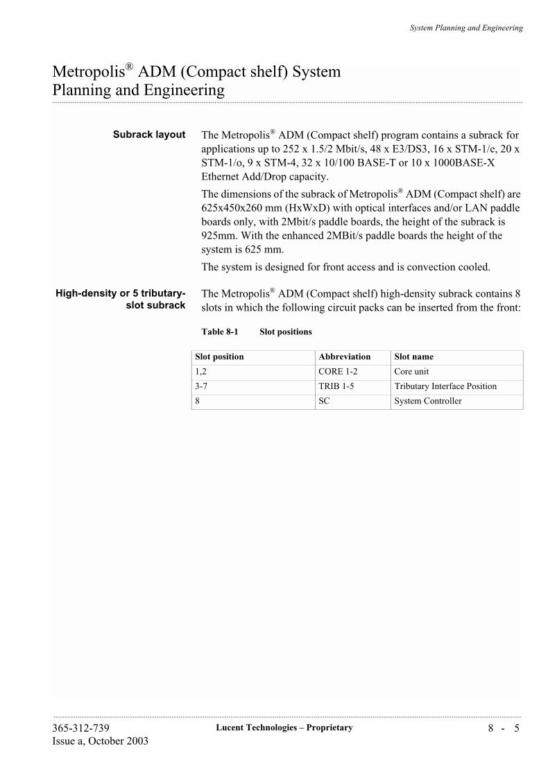
System Planning and Engineering
8 - 5Lucent Technologies – Proprietary365-312-739Issue a, October 2003
..............................................................................................................................................................................................................................................................
Metropolis® ADM (Compact shelf) System
...............................................................................................................................................................................................................................................................Planning and Engineering
Subrack layout The Metropolis® ADM (Compact shelf) program contains a subrack for applications up to 252 x 1.5/2 Mbit/s, 48 x E3/DS3, 16 x STM-1/e, 20 x STM-1/o, 9 x STM-4, 32 x 10/100 BASE-T or 10 x 1000BASE-X Ethernet Add/Drop capacity.
The dimensions of the subrack of Metropolis® ADM (Compact shelf) are 625x450x260 mm (HxWxD) with optical interfaces and/or LAN paddle boards only, with 2Mbit/s paddle boards, the height of the subrack is 925mm. With the enhanced 2MBit/s paddle boards the height of the system is 625 mm.
The system is designed for front access and is convection cooled.
High-density or 5 tributary-slot subrack
The Metropolis® ADM (Compact shelf) high-density subrack contains 8 slots in which the following circuit packs can be inserted from the front:
Table 8-1 Slot positions
Slot position Abbreviation Slot name
1,2 CORE 1-2 Core unit
3-7 TRIB 1-5 Tributary Interface Position
8 SC System Controller
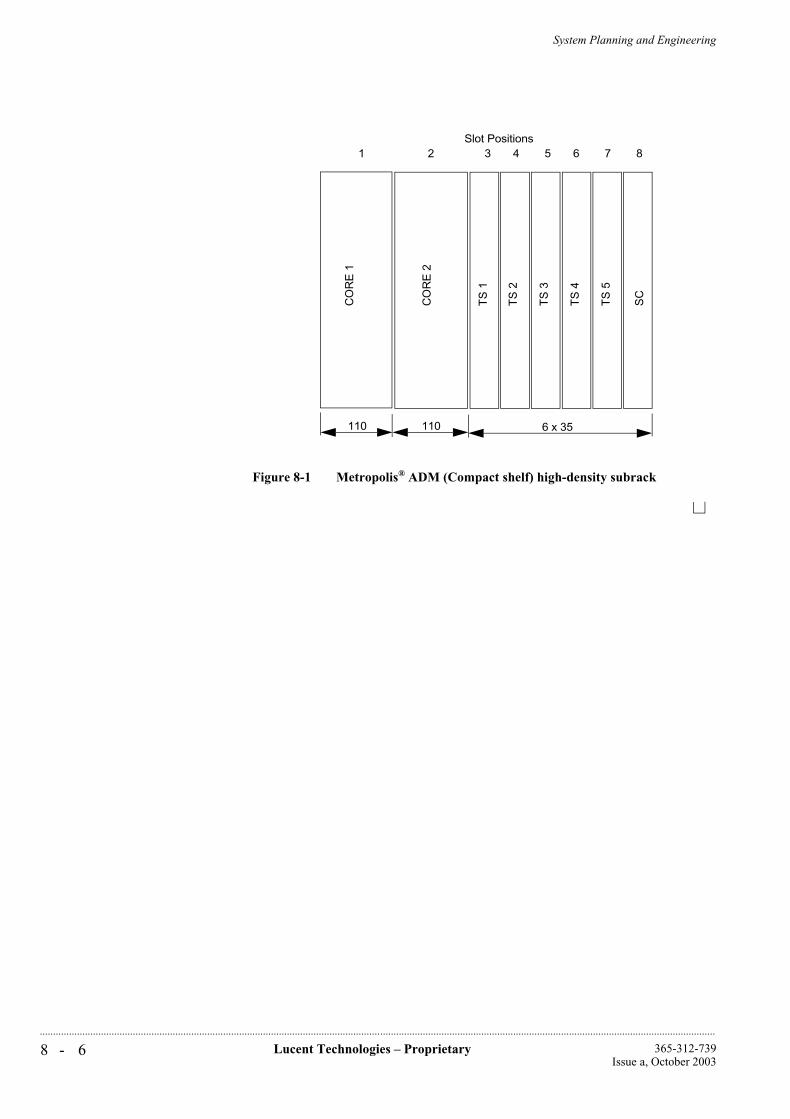
System Planning and Engineering
8 - 6 Lucent Technologies – Proprietary 365-312-739Issue a, October 2003
..............................................................................................................................................................................................................................................................
Figure 8-1 Metropolis® ADM (Compact shelf) high-density subrackT
S 1
SC
CO
RE
1
CO
RE
2
TS
2
TS
3
TS
4
TS
5
110 110 6 x 35
Slot Positions1 2 3 4 5 6 7 8
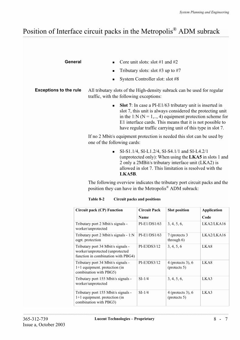
System Planning and Engineering
8 - 7Lucent Technologies – Proprietary365-312-739Issue a, October 2003
..............................................................................................................................................................................................................................................................
...............................................................................................................................................................................................................................................................Position of Interface circuit packs in the Metropolis® ADM subrack
General Core unit slots: slot #1 and #2
Tributary slots: slot #3 up to #7
System Controller slot: slot #8
Exceptions to the rule All tributary slots of the High-density subrack can be used for regular traffic, with the following exceptions:
Slot 7: In case a PI-E1/63 tributary unit is inserted in slot 7, this unit is always considered the protecting unit in the 1:N (N = 1,.., 4) equipment protection scheme for E1 interface cards. This means that it is not possible to have regular traffic carrying unit of this type in slot 7.
If no 2 Mbit/s equipment protection is needed this slot can be used by one of the following cards:
SI-S1.1/4, SI-L1.2/4, SI-S4.1/1 and SI-L4.2/1 (unprotected only): When using the LKA5 in slots 1 and 2 only a 2MBit/s tributary interface unit (LKA2) is allowed in slot 7. This limitation is resolved with the LKA5B.
The following overview indicates the tributary port circuit packs and the position they can have in the Metropolis® ADM subrack:
Table 8-2 Circuit packs and positions
Circuit pack (CP) Function Circuit Pack
Name
Slot position Application
Code
Tributary port 2 Mbit/s signals - worker/unprotected
PI-E1/DS1/63 3, 4, 5, 6, LKA2/LKA16
Tributary port 2 Mbit/s signals - 1:N eqpt. protection
PI-E1/DS1/63 7 (protects 3 through 6)
LKA2/LKA16
Tributary port 34 Mbit/s signals - worker/unprotected (unprotected function in combination with PBG4)
PI-E3DS3/12 3, 4, 5, 6 LKA8
Tributary port 34 Mbit/s signals - 1+1 equipment. protection (in combination with PBG5)
PI-E3DS3/12 4 (protects 3), 6 (protects 5)
LKA8
Tributary port 155 Mbit/s signals - worker/unprotected
SI-1/4 3, 4, 5, 6, LKA3
Tributary port 155 Mbit/s signals - 1+1 equipment. protection (in combination with PBG3)
SI-1/4 4 (protects 3), 6 (protects 5)
LKA3
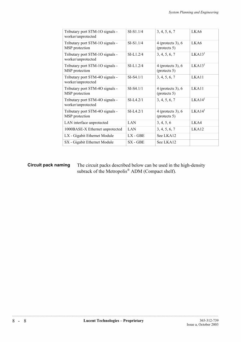
System Planning and Engineering
8 - 8 Lucent Technologies – Proprietary 365-312-739Issue a, October 2003
..............................................................................................................................................................................................................................................................
Circuit pack naming The circuit packs described below can be used in the high-density subrack of the Metropolis® ADM (Compact shelf).
Tributary port STM-1O signals - worker/unprotected
SI-S1.1/4 3, 4, 5, 6, 7 LKA6
Tributary port STM-1O signals - MSP protection
SI-S1.1/4 4 (protects 3), 6 (protects 5)
LKA6
Tributary port STM-1O signals - worker/unprotected
SI-L1.2/4 3, 4, 5, 6, 7 LKA131
Tributary port STM-1O signals - MSP protection
SI-L1.2/4 4 (protects 3), 6 (protects 5)
LKA131
Tributary port STM-4O signals - worker/unprotected
SI-S4.1/1 3, 4, 5, 6, 7 LKA11
Tributary port STM-4O signals - MSP protection
SI-S4.1/1 4 (protects 3), 6 (protects 5)
LKA11
Tributary port STM-4O signals - worker/unprotected
SI-L4.2/1 3, 4, 5, 6, 7 LKA141
Tributary port STM-4O signals - MSP protection
SI-L4.2/1 4 (protects 3), 6 (protects 5)
LKA141
LAN interface unprotected LAN 3, 4, 5, 6 LKA4
1000BASE-X Ethernet unprotected LAN 3, 4, 5, 6, 7 LKA12
LX - Gigabit Ethernet Module LX - GBE See LKA12
SX - Gigabit Ethernet Module SX - GBE See LKA12
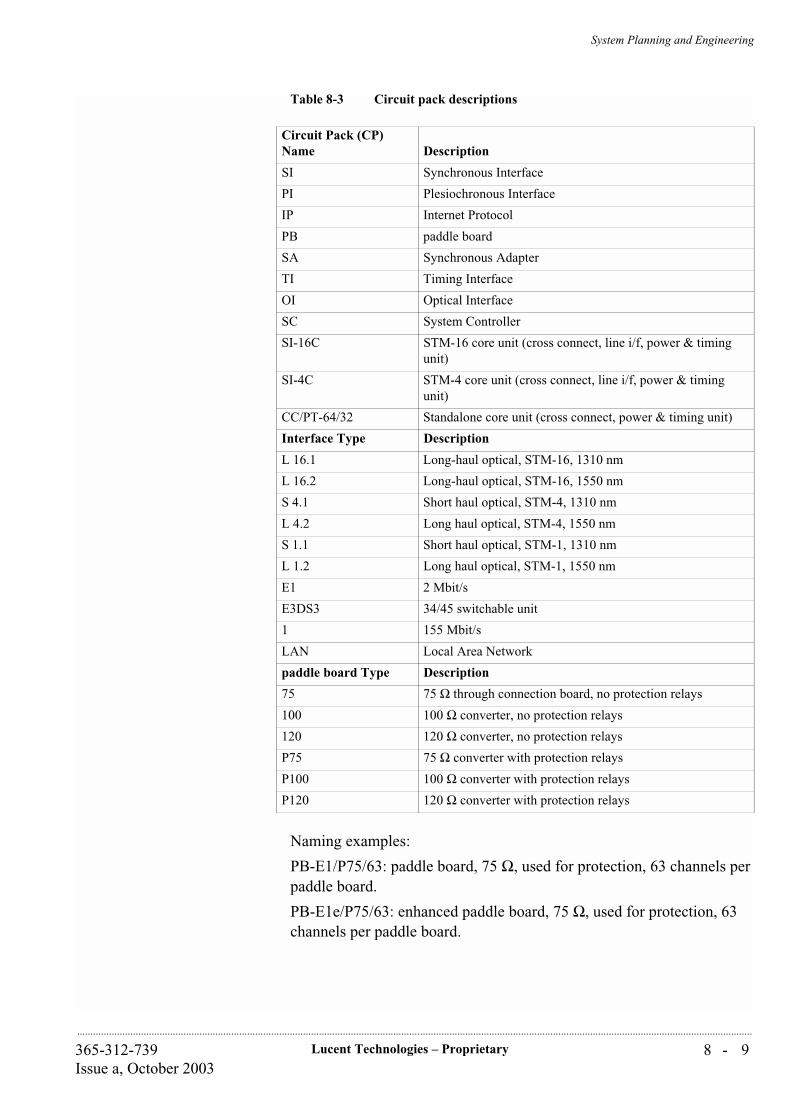
System Planning and Engineering
8 - 9Lucent Technologies – Proprietary365-312-739Issue a, October 2003
..............................................................................................................................................................................................................................................................
Table 8-3 Circuit pack descriptions
Naming examples:
PB-E1/P75/63: paddle board, 75 Ω, used for protection, 63 channels per paddle board.
PB-E1e/P75/63: enhanced paddle board, 75 Ω, used for protection, 63 channels per paddle board.
Circuit Pack (CP) Name Description
SI Synchronous Interface
PI Plesiochronous Interface
IP Internet Protocol
PB paddle board
SA Synchronous Adapter
TI Timing Interface
OI Optical Interface
SC System Controller
SI-16C STM-16 core unit (cross connect, line i/f, power & timing unit)
SI-4C STM-4 core unit (cross connect, line i/f, power & timing unit)
CC/PT-64/32 Standalone core unit (cross connect, power & timing unit)
Interface Type Description
L 16.1 Long-haul optical, STM-16, 1310 nm
L 16.2 Long-haul optical, STM-16, 1550 nm
S 4.1 Short haul optical, STM-4, 1310 nm
L 4.2 Long haul optical, STM-4, 1550 nm
S 1.1 Short haul optical, STM-1, 1310 nm
L 1.2 Long haul optical, STM-1, 1550 nm
E1 2 Mbit/s
E3DS3 34/45 switchable unit
1 155 Mbit/s
LAN Local Area Network
paddle board Type Description
75 75 Ω through connection board, no protection relays
100 100 Ω converter, no protection relays
120 120 Ω converter, no protection relays
P75 75 Ω converter with protection relays
P100 100 Ω converter with protection relays
P120 120 Ω converter with protection relays
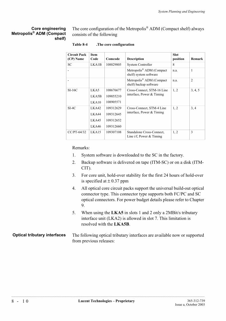
System Planning and Engineering
8 - 1 0 Lucent Technologies – Proprietary 365-312-739Issue a, October 2003
..............................................................................................................................................................................................................................................................
Core engineeringMetropolis® ADM (Compact
shelf)
The core configuration of the Metropolis® ADM (Compact shelf) always consists of the following
Table 8-4 .The core configuration
Remarks:
1. System software is downloaded to the SC in the factory.
2. Backup software is delivered on tape (ITM-SC) or on a disk (ITM-CIT).
3. For core unit, hold-over stability for the first 24 hours of hold-over is specified at ± 0.37 ppm
4. All optical core circuit packs support the universal build-out optical connector type. This connector type supports both FC/PC and SC optical connectors. For power budget details please refer to Chapter 9.
5. When using the LKA5 in slots 1 and 2 only a 2MBit/s tributary interface unit (LKA2) is allowed in slot 7. This limitation is resolved with the LKA5B.
Optical tributary interfaces The following optical tributary interfaces are available now or supported from previous releases:
Circuit Pack (CP) Name
Item Code Comcode Description
Slot position Remark
SC LKA1B 108829805 System Controller 8
- Metropolis® ADM (Compact shelf) system software
n.a. 1
- Metropolis® ADM (Compact shelf) backup software
n.a. 2
SI-16C LKA5
LKA5B
LKA10
108676677
109055210
108905571
Cross-Connect, STM-16 Line interface, Power & Timing
1, 2 3, 4, 5
SI-4C LKA42
LKA44
LKA45
LKA46
109312629
109312645
109312652
109312660
Cross-Connect, STM-4 Line interface, Power & Timing
1, 2 3, 4
CC/PT-64/32 LKA15 109307108 Standalone Cross-Connect, Line i/f, Power & Timing
1, 2 3

System Planning and Engineering
8 - 1 1Lucent Technologies – Proprietary365-312-739Issue a, October 2003
..............................................................................................................................................................................................................................................................
Table 8-5 Optical tributary interfaces
Remarks:
1. Slot 7 can only support unprotected board, protected boards are placed in slot 4 and 6.
2. When using the LKA5 in slots 1 and 2 only a 2MBit/s tributary interface unit (LKA2) is allowed in slot 7. This limitation is resolved with the LKA5B.
Electrical tributaryinterfaces
The following electrical tributary interfaces are available now or supported from previous releases:
Circuit Pack (CP) Name
Item Code Comcode Description
Slot position Remark
SI-S1.1/4 LKA6 108680042 Optical Short haul STM-1 1310 nm; 4 Interfaces per circuit pack
3-7 1,2
SI-L1.2/4 LKA13 109202291 Optical Long haul STM-1 1550 nm; 4 Interfaces per circuit pack
3-7 1,2,3
SI-S4.1/1 LKA11 109047811 Optical Short haul STM-4 1310 nm; 1 Interfaces per circuit pack
3-7 1,2
SI-L4.2/1 LKA14 109202309 Optical Long haul STM-4 1550 nm; 1 Interfaces per circuit pack
3-7 1,2,3
IP-GE/2 LKA12 109198259 1000BASE-X Ethernet 3-7
LX - GBE OMGBE-LX
109294694 LX - Gigabit Ethernet Module
See LKA12
SX - GBE OMGBE-SX
109294702 SX - Gigabit Ethernet Module
See LKA12
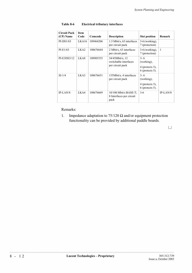
System Planning and Engineering
8 - 1 2 Lucent Technologies – Proprietary 365-312-739Issue a, October 2003
..............................................................................................................................................................................................................................................................
Table 8-6 Electrical tributary interfaces
Remarks:
1. Impedance adaptation to 75/120 Ω and/or equipment protection functionality can be provided by additional paddle boards.
Circuit Pack (CP) Name
Item Code Comcode Description Slot position Remark
PI-DS1/63 LKA16 109464206 1.5 Mbit/s, 63 interfaces per circuit pack
3-6 (working), 7 (protection)
PI-E1/63 LKA2 108676644 2 Mbit/s, 63 interfaces per circuit pack
3-6 (working), 7 (protection)
1
PI-E3DS3/12 LKA8 108905555 34/45Mbit/s, 12 switchable interfaces per circuit pack
3- 6 (working),
4 (protects 3), 6 (protects 5).
SI-1/4 LKA3 108676651 155Mbit/s, 4 interfaces per circuit pack
3- 6 (working),
4 (protects 3), 6 (protects 5).
IP-LAN/8 LKA4 108676669 10/100 Mbit/s BASE-T; 8 Interfaces per circuit pack
3-6 IP-LAN/8

System Planning and Engineering
8 - 1 3Lucent Technologies – Proprietary365-312-739Issue a, October 2003
..............................................................................................................................................................................................................................................................
...............................................................................................................................................................................................................................................................Paddle boards (electrical interfaces)
Type of paddle boards A variety of paddle boards exist to interconnect the system to the office cabling. Paddle boards are available for unprotected or protected applications with or without impedance adaptation.
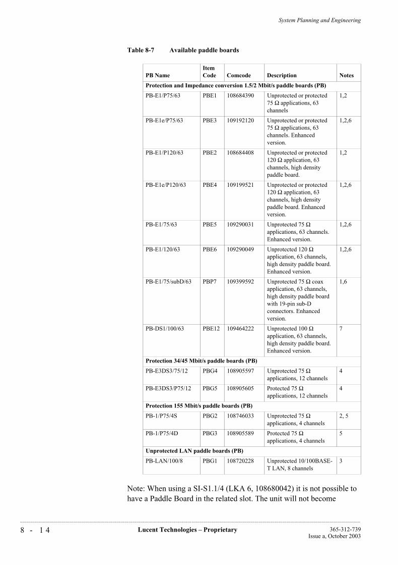
System Planning and Engineering
8 - 1 4 Lucent Technologies – Proprietary 365-312-739Issue a, October 2003
..............................................................................................................................................................................................................................................................
Table 8-7 Available paddle boards
Note: When using a SI-S1.1/4 (LKA 6, 108680042) it is not possible to have a Paddle Board in the related slot. The unit will not become
PB NameItem Code Comcode Description Notes
Protection and Impedance conversion 1.5/2 Mbit/s paddle boards (PB)
PB-E1/P75/63 PBE1 108684390 Unprotected or protected 75 Ω applications, 63 channels
1,2
PB-E1e/P75/63 PBE3 109192120 Unprotected or protected 75 Ω applications, 63 channels. Enhanced version.
1,2,6
PB-E1/P120/63 PBE2 108684408 Unprotected or protected 120 Ω application, 63 channels, high density paddle board.
1,2
PB-E1e/P120/63 PBE4 109199521 Unprotected or protected 120 Ω application, 63 channels, high density paddle board. Enhanced version.
1,2,6
PB-E1/75/63 PBE5 109290031 Unprotected 75 Ω applications, 63 channels. Enhanced version.
1,2,6
PB-E1/120/63 PBE6 109290049 Unprotected 120 Ω application, 63 channels, high density paddle board. Enhanced version.
1,2,6
PB-E1/75/subD/63 PBP7 109399592 Unprotected 75 Ω coax application, 63 channels, high density paddle board with 19-pin sub-D connectors. Enhanced version.
1,6
PB-DS1/100/63 PBE12 109464222 Unprotected 100 Ω application, 63 channels, high density paddle board. Enhanced version.
7
Protection 34/45 Mbit/s paddle boards (PB)
PB-E3DS3/75/12 PBG4 108905597 Unprotected 75 Ω applications, 12 channels
4
PB-E3DS3/P75/12 PBG5 108905605 Protected 75 Ω applications, 12 channels
4
Protection 155 Mbit/s paddle boards (PB)
PB-1/P75/4S PBG2 108746033 Unprotected 75 Ω applications, 4 channels
2, 5
PB-1/P75/4D PBG3 108905589 Protected 75 Ω applications, 4 channels
5
Unprotected LAN paddle boards (PB)
PB-LAN/100/8 PBG1 108720228 Unprotected 10/100BASE-T LAN, 8 channels
3

System Planning and Engineering
8 - 1 5Lucent Technologies – Proprietary365-312-739Issue a, October 2003
..............................................................................................................................................................................................................................................................
operational.
Remarks:
1. This paddle board can be used with the PI-E1/63. PBE1/2 are in form of single paddle board long and PBE3/4/5/6 are single paddle board short.
2. The paddle can work both for unprotected and protected board.
3. This paddle board must be used with the IP-LAN/8. PBG1 is in form of single paddle board short.
4. This paddle board can be used with the PI-E3DS3/12. PBG4 is in form of single paddle board short and PBG5 is parallel paddle board short.
5. This paddle board can be used with the SI-1/4. PBG2 is in form of single paddle board short and PBG3 is parallel paddle board short.
6. With Enhanced Paddle Boards for 2MBit/s interfaces the height of the system is 625 mm.
7. This paddle board can be used with the PI-DS1/63. PBE12 is in form of single paddle board short.

System Planning and Engineering
8 - 1 6 Lucent Technologies – Proprietary 365-312-739Issue a, October 2003
..............................................................................................................................................................................................................................................................
...............................................................................................................................................................................................................................................................Configurations
Overview Some of typical configurations are given in this chapter. The basic configuration rules are:
Two core units are needed for protection of Cross connect, Power & Timing and Line interface.
Slot 3-6 can be configured with 1.5Mbit/s, 2MBit/s, 34MBit/s, 45MBit/s, STM-1e, 10/100 BASE-T LAN, STM-1o, STM-4o or 1000BASE-X LAN interface.
If 34MBit/s or 45MBit/s equipment protection is used, slot 4 and 6 are used for the protection board, slot 3 and 5 are used for the working board.
If STM-1e 1+1 equipment protection is used, slot 4 and 6 are used for the protection board, slot 3 and 5 are used for the working boards.
If STM-1o or STM-4o 1+1 MSP is used, slot 4 and 6 are used for the protection board, slot 3 and 5 are used for the working board.
Slot 7 can be configured with STM-1o, STM-4o or 1000BASE-X LAN without protection, if used for 1.5Mbit/s or 2MBit/s, it can only be used for the protection board. No LAN board is supported in slot 7.
Orderable items The following table shows the orderable items of the Metropolis® ADM (Compact Shelf):
Table 8-8 Orderable items
Item CodeCircuit Pack (CP) Name Comcode Description
Rack
- - 848586780 Rack 600x300x2200 ETSI
- - 848586798 Rack 600x300x2600 ETSI
- PDP10 848385936 Power Distribution Panel
- PDR 2 848808796 Power Distribution Rail
Subracks
EHA1 EHA1 848516589 High-density subrack
- - 848556239 Cable and Connector kit
Core circuit packs
LKA1B SC 108829805 System Controller
SCA207C - 109436469 System SW/Init.Downld. R3.2
SCA208C - 109436477 System Software Disk R3.2
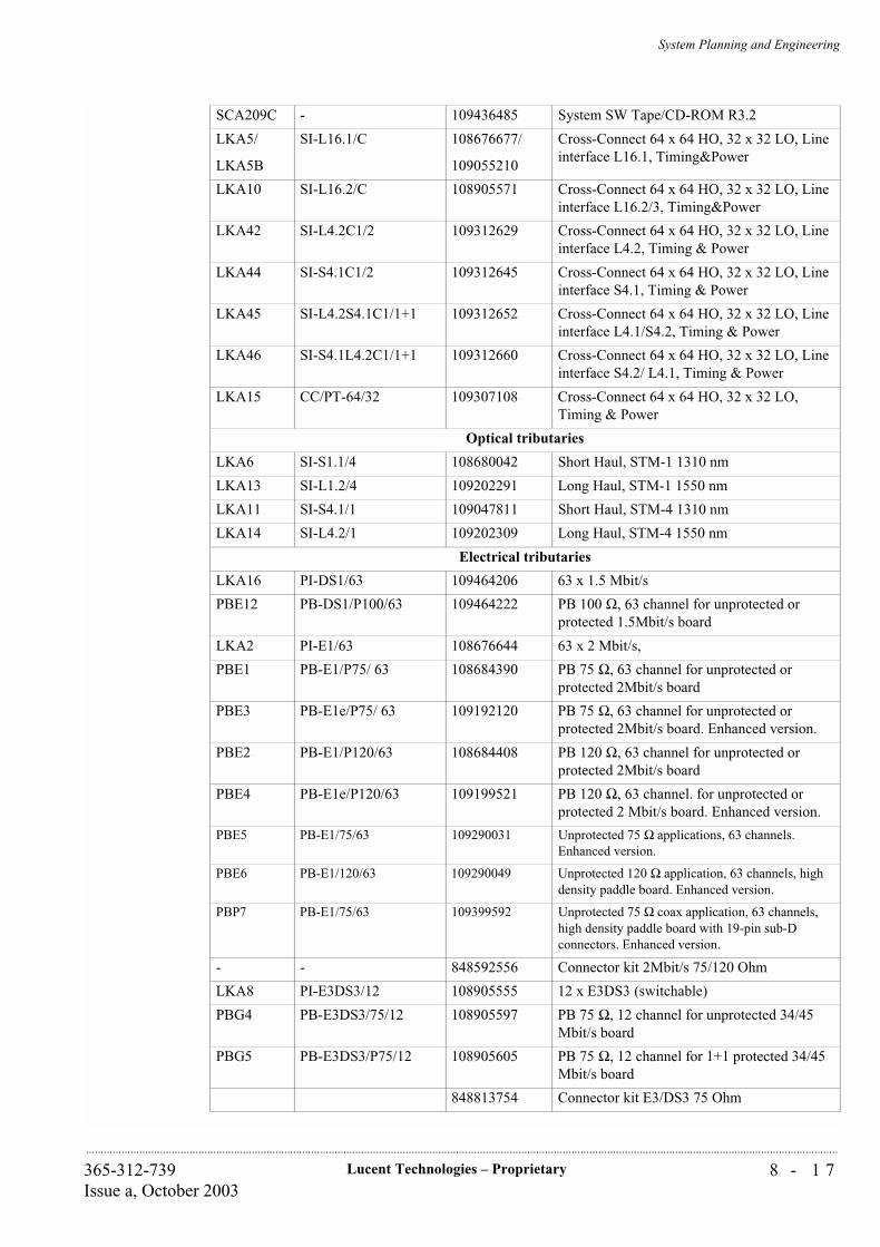
System Planning and Engineering
8 - 1 7Lucent Technologies – Proprietary365-312-739Issue a, October 2003
..............................................................................................................................................................................................................................................................
SCA209C - 109436485 System SW Tape/CD-ROM R3.2
LKA5/
LKA5B
SI-L16.1/C 108676677/
109055210
Cross-Connect 64 x 64 HO, 32 x 32 LO, Line interface L16.1, Timing&Power
LKA10 SI-L16.2/C 108905571 Cross-Connect 64 x 64 HO, 32 x 32 LO, Line interface L16.2/3, Timing&Power
LKA42 SI-L4.2C1/2 109312629 Cross-Connect 64 x 64 HO, 32 x 32 LO, Line interface L4.2, Timing & Power
LKA44 SI-S4.1C1/2 109312645 Cross-Connect 64 x 64 HO, 32 x 32 LO, Line interface S4.1, Timing & Power
LKA45 SI-L4.2S4.1C1/1+1 109312652 Cross-Connect 64 x 64 HO, 32 x 32 LO, Line interface L4.1/S4.2, Timing & Power
LKA46 SI-S4.1L4.2C1/1+1 109312660 Cross-Connect 64 x 64 HO, 32 x 32 LO, Line interface S4.2/ L4.1, Timing & Power
LKA15 CC/PT-64/32 109307108 Cross-Connect 64 x 64 HO, 32 x 32 LO, Timing & Power
Optical tributaries
LKA6 SI-S1.1/4 108680042 Short Haul, STM-1 1310 nm
LKA13 SI-L1.2/4 109202291 Long Haul, STM-1 1550 nm
LKA11 SI-S4.1/1 109047811 Short Haul, STM-4 1310 nm
LKA14 SI-L4.2/1 109202309 Long Haul, STM-4 1550 nm
Electrical tributaries
LKA16 PI-DS1/63 109464206 63 x 1.5 Mbit/s
PBE12 PB-DS1/P100/63 109464222 PB 100 Ω, 63 channel for unprotected or protected 1.5Mbit/s board
LKA2 PI-E1/63 108676644 63 x 2 Mbit/s,
PBE1 PB-E1/P75/ 63 108684390 PB 75 Ω, 63 channel for unprotected or protected 2Mbit/s board
PBE3 PB-E1e/P75/ 63 109192120 PB 75 Ω, 63 channel for unprotected or protected 2Mbit/s board. Enhanced version.
PBE2 PB-E1/P120/63 108684408 PB 120 Ω, 63 channel for unprotected or protected 2Mbit/s board
PBE4 PB-E1e/P120/63 109199521 PB 120 Ω, 63 channel. for unprotected or protected 2 Mbit/s board. Enhanced version.
PBE5 PB-E1/75/63 109290031 Unprotected 75 Ω applications, 63 channels. Enhanced version.
PBE6 PB-E1/120/63 109290049 Unprotected 120 Ω application, 63 channels, high density paddle board. Enhanced version.
PBP7 PB-E1/75/63 109399592 Unprotected 75 Ω coax application, 63 channels, high density paddle board with 19-pin sub-D connectors. Enhanced version.
- - 848592556 Connector kit 2Mbit/s 75/120 Ohm
LKA8 PI-E3DS3/12 108905555 12 x E3DS3 (switchable)
PBG4 PB-E3DS3/75/12 108905597 PB 75 Ω, 12 channel for unprotected 34/45 Mbit/s board
PBG5 PB-E3DS3/P75/12 108905605 PB 75 Ω, 12 channel for 1+1 protected 34/45 Mbit/s board
848813754 Connector kit E3/DS3 75 Ohm

System Planning and Engineering
8 - 1 8 Lucent Technologies – Proprietary 365-312-739Issue a, October 2003
..............................................................................................................................................................................................................................................................
Remarks:
1. Two SICT are needed for all applications.
2. One used for working, one used for 1:N protection.
3. One used for working, one used for 1+1 protection.
4. With Enhanced Paddle Boards for 2MBit/s interfaces the height of the system is 625 mm.
5. 1+1 MSP, slot 3&4, 5&6
LKA3 SI-1/4 108676651 4 x STM-1e
PBG2 PB-1/P75/4S 108746033 PB 4 channel for unprotected STM-1e boards
PBG3 PB-1/P75/4D 108905589 PB 4 channel for 1+1 protected STM-1e board
848813762 Connector kit STM-1/e 75 Ohm
LKA4 IP-LAN/8 108676669 10/100 Base-T LAN interface, 8 ports.
PBG1 PB-LAN/8 108720228 PB LAN ports, 8 channel
848592549 Connector kit Lan
Miscellaneous
106795404 FC/PC Lightguide buildout (0 dB)
107406233 FC/PC Lightguide Buildout (10 dB)
106708951 SC Lightguide buildout (0 dB)
107406159 SC Lightguide Buildout (10 dB)
106908387 Single fibre SC 20 SM SC
847692811 Single fibre FC 20 SM PC
Documentation
109494302 Metropolis® ADM (Compact Shelf) Application and Planning Guide
109494369 Metropolis® ADM (Compact Shelf) Installation Guide
109494377 Metropolis® ADM (Compact Shelf) User Operations Guide
109494310 Metropolis® ADM (Compact Shelf) Alarm Messages and Trouble Clearing Guide
109494336 Metropolis® ADM (Compact Shelf) ITM-SC Provisioning Guide
109494344 Metropolis® ADM (Compact Shelf) Release Notes
109501718 Metropolis® ADM (Compact Shelf) Assembly Guide
109494328 Metropolis® ADM (Compact Shelf) Customer Documentation CD-ROM

System Planning and Engineering
8 - 1 9Lucent Technologies – Proprietary365-312-739Issue a, October 2003
..............................................................................................................................................................................................................................................................

Lucent Technologies – ProprietarySee notice on first page
365-312-739Issue a, October 2003
...........................................................................................................................................................................................................................................................
System Planning and Engineering
9 - 1Lucent Technologies – Proprietary365-312-739Issue a, October 2003
..............................................................................................................................................................................................................................................................
9 Technical Data
...............................................................................................................................................................................................................................................................Overview
This chapter contains the technical specifications of the Metropolis® ADM (Compact shelf).
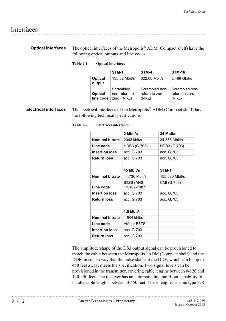
Technical Data
9 - 2 Lucent Technologies – Proprietary 365-312-739Issue a, October 2003
..............................................................................................................................................................................................................................................................
...............................................................................................................................................................................................................................................................Interfaces
Optical interfaces The optical interfaces of the Metropolis® ADM (Compact shelf) have the following optical outputs and line codes.
Electrical interfaces The electrical interfaces of the Metropolis® ADM (Compact shelf) have the following technical specifications.
The amplitude/shape of the DS3 output signal can be provisioned to match the cable between the Metropolis® ADM (Compact shelf) and the DDF, in such a way that the pulse shape at the DDF, which can be up to 450 feet away, meets the specification. Two signal levels can be provisioned in the transmitter, covering cable lengths between 0-120 and 120-450 feet. The receiver has an automatic line build-out capability to handle cable lengths between 0-450 feet. These lengths assume type 728
Table 9-1 Optical interfaces
STM-1 STM-4 STM-16
Optical output
155.52 Mbit/s 622.08 Mbit/s 2.488 Gbit/s
Optical line code
Scrambled non-return to zero, (NRZ)
Scrambled non-return to zero, (NRZ)
Scrambled non-return to zero, (NRZ)
Table 9-2 Electrical interfaces
2 Mbit/s 34 Mbit/s
Nominal bitrate 2048 kbit/s 34.368 Mbit/s
Line code HDB3 (G.703) HDB3 (G.703)
Insertion loss acc. G.703 acc. G.703
Return loss acc. G.703 acc. G.703
45 Mbit/s STM-1
Nominal bitrate 44.736 Mbit/s 155.520 Mbit/s
Line codeB3ZS (ANSI T1.102-1987)
CMI (G.703)
Insertion loss acc. G.703 acc. G.703
Return loss acc. G.703 acc. G.703
1.5 Mbit/
Nominal bitrate 1.544 kbit/s
Line code AMI or B8ZS
Insertion loss acc. G.703
Return loss acc. G.703

Technical Data
9 - 3Lucent Technologies – Proprietary365-312-739Issue a, October 2003
..............................................................................................................................................................................................................................................................
cable (Telcordia GR-139-CORE) with an approximate √f transfer and an attenuation of 5.7 dB and a phase rotation of 38° at a frequency of 22.368 MHz.
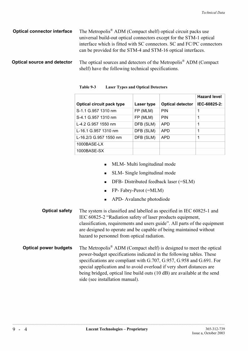
Technical Data
9 - 4 Lucent Technologies – Proprietary 365-312-739Issue a, October 2003
..............................................................................................................................................................................................................................................................
Optical connector interface The Metropolis® ADM (Compact shelf) optical circuit packs use universal build-out optical connectors except for the STM-1 optical interface which is fitted with SC connectors. SC and FC/PC connectors can be provided for the STM-4 and STM-16 optical interfaces.
Optical source and detector The optical sources and detectors of the Metropolis® ADM (Compact shelf) have the following technical specifications.
MLM- Multi longitudinal mode
SLM- Single longitudinal mode
DFB- Distributed feedback laser (=SLM)
FP- Fabry-Perot (=MLM)
APD- Avalanche photodiode
Optical safety The system is classified and labelled as specified in IEC 60825-1 and IEC 60825-2 “Radiation safety of laser products equipment, classification, requirements and users guide”. All parts of the equipment are designed to operate and be capable of being maintained without hazard to personnel from optical radiation.
Optical power budgets The Metropolis® ADM (Compact shelf) is designed to meet the optical power-budget specifications indicated in the following tables. These specifications are compliant with G.707, G.957, G.958 and G.691. For special application and to avoid overload if very short distances are being bridged, optical line build outs (10 dB) are available at the send side (see installation manual).
Table 9-3 Laser Types and Optical Detectors
Optical circuit pack type Laser type Optical detector
Hazard level
IEC-60825-2:
S-1.1 G.957 1310 nm FP (MLM) PIN 1
S-4.1 G.957 1310 nm FP (MLM) PIN 1
L-4.2 G.957 1550 nm DFB (SLM) APD 1
L-16.1 G.957 1310 nm DFB (SLM) APD 1
L-16.2/3 G.957 1550 nm DFB (SLM) APD 1
1000BASE-LX
1000BASE-SX
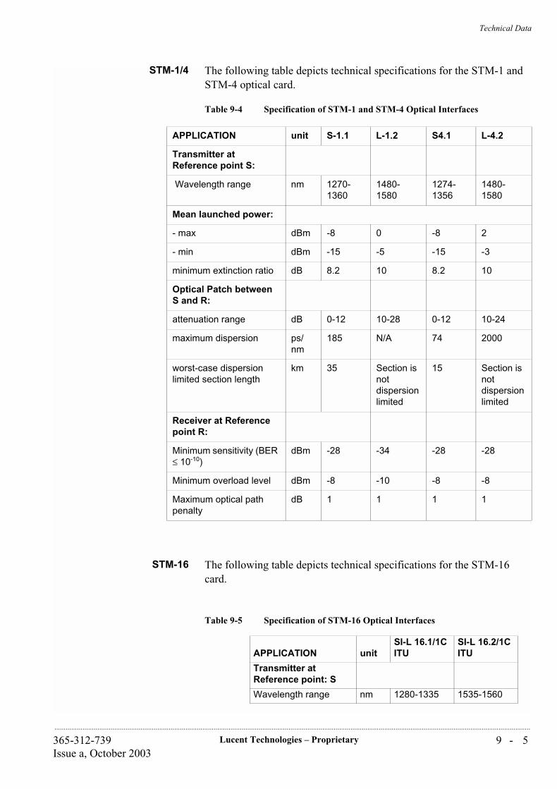
Technical Data
9 - 5Lucent Technologies – Proprietary365-312-739Issue a, October 2003
..............................................................................................................................................................................................................................................................
STM-1/4 The following table depicts technical specifications for the STM-1 and STM-4 optical card.
Table 9-4 Specification of STM-1 and STM-4 Optical Interfaces
STM-16 The following table depicts technical specifications for the STM-16 card.
APPLICATION unit S-1.1 L-1.2 S4.1 L-4.2
Transmitter at Reference point S:
Wavelength range nm 1270-1360
1480-1580
1274-1356
1480-1580
Mean launched power:
- max dBm -8 0 -8 2
- min dBm -15 -5 -15 -3
minimum extinction ratio dB 8.2 10 8.2 10
Optical Patch between S and R:
attenuation range dB 0-12 10-28 0-12 10-24
maximum dispersion ps/nm
185 N/A 74 2000
worst-case dispersion limited section length
km 35 Section is not dispersion limited
15 Section is not dispersion limited
Receiver at Reference point R:
Minimum sensitivity (BER ≤ 10-10)
dBm -28 -34 -28 -28
Minimum overload level dBm -8 -10 -8 -8
Maximum optical path penalty
dB 1 1 1 1
Table 9-5 Specification of STM-16 Optical Interfaces
APPLICATION unitSI-L 16.1/1C ITU
SI-L 16.2/1C ITU
Transmitter at Reference point: S
Wavelength range nm 1280-1335 1535-1560
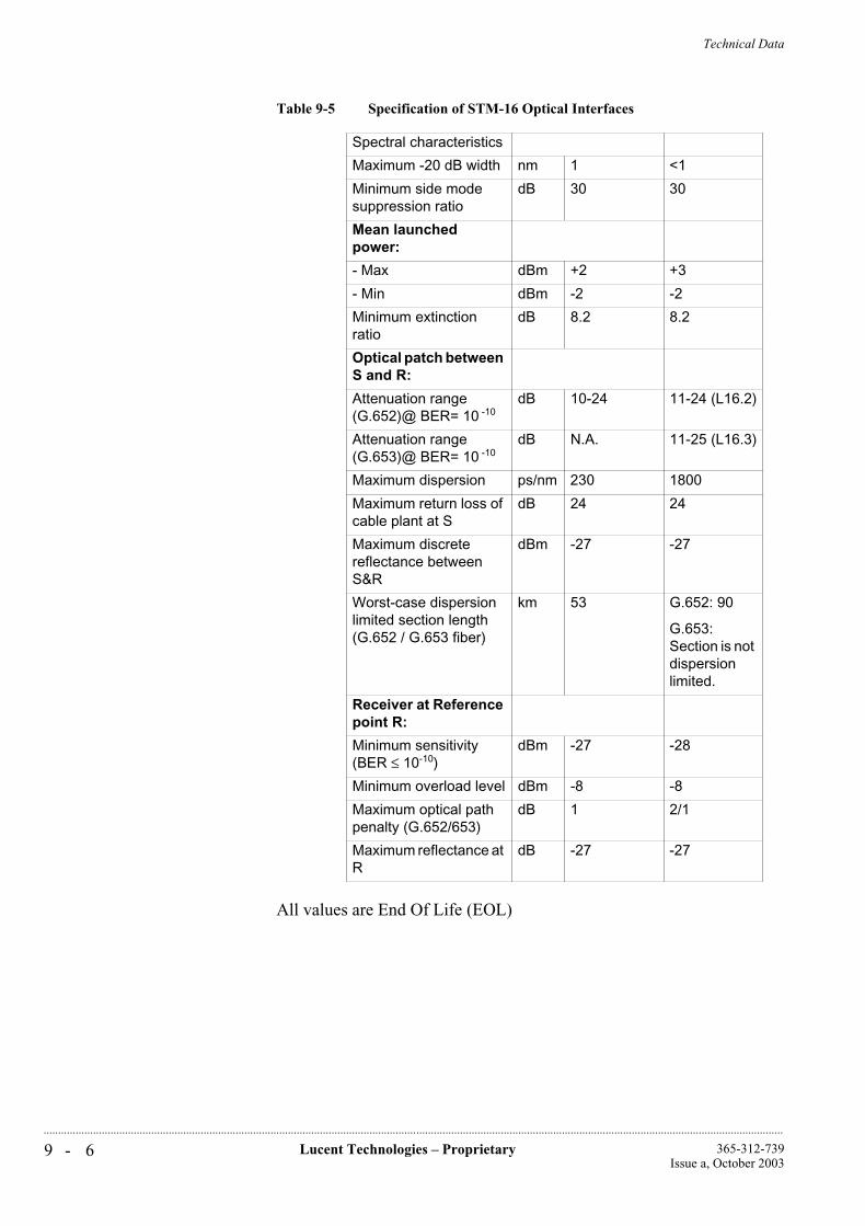
Technical Data
9 - 6 Lucent Technologies – Proprietary 365-312-739Issue a, October 2003
..............................................................................................................................................................................................................................................................
All values are End Of Life (EOL)
Spectral characteristics
Maximum -20 dB width nm 1 <1
Minimum side mode suppression ratio
dB 30 30
Mean launched power:
- Max dBm +2 +3
- Min dBm -2 -2
Minimum extinction ratio
dB 8.2 8.2
Optical patch between S and R:
Attenuation range (G.652)@ BER= 10 -10
dB 10-24 11-24 (L16.2)
Attenuation range (G.653)@ BER= 10 -10
dB N.A. 11-25 (L16.3)
Maximum dispersion ps/nm 230 1800
Maximum return loss of cable plant at S
dB 24 24
Maximum discrete reflectance between S&R
dBm -27 -27
Worst-case dispersion limited section length (G.652 / G.653 fiber)
km 53 G.652: 90
G.653: Section is not dispersion limited.
Receiver at Reference point R:
Minimum sensitivity (BER ≤ 10-10)
dBm -27 -28
Minimum overload level dBm -8 -8
Maximum optical path penalty (G.652/653)
dB 1 2/1
Maximum reflectance at R
dB -27 -27
Table 9-5 Specification of STM-16 Optical Interfaces

Technical Data
9 - 7Lucent Technologies – Proprietary365-312-739Issue a, October 2003
..............................................................................................................................................................................................................................................................
Table 9-6 Specifications of 1000BASE-X Interface
Remarks:
1. Link penalties are used for link budget calculations. They are not requirements and are meant to be tested.
2. Dependent on the modal bandwidth the operating distance can be shorter.
3. A wavelength of 830 nm is used to calculate channel insertion loss, link power penalties and unallocted margin.
4. A wavelength of 1270 nm is used to calculate channel insertion loss, link power penalties and unallocted margin.
1000BASE-SX 1000BASE-LX
Mean launched power:
- Max dBm 0
-9.5
9
-3
-11
9
- Min dBm
Minimum extinction ratio
dB
Worst case link power budget and penaltis:
Fiber typ 62.5 um MMF
50 um MMF 62.5 um MMF, 50 um MMF
10 um SMF
Modal bandwith MHz*km
200 500 400, 500 NA
Link power budget dB 7.5 7.5 7.5 8
Channel insertion loss dB 2.6(3) 3.6(3) 2.35(4) 4.6(4)
Link power penalties(1) dB 4.3 3.6 5.1 3.3
Operating distance m 2 to 275(2) 2 to 550(2) 2 to 550 2 to 5000
Receive characteristics at point TP3:
Minimum sensitivity (BER = 10-12)
dBm -17 -19
Average receive power (Max.)
dBm 0 -3
Return loss dB 12 12
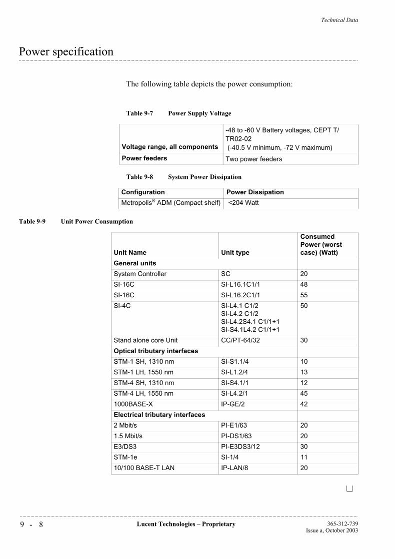
Technical Data
9 - 8 Lucent Technologies – Proprietary 365-312-739Issue a, October 2003
..............................................................................................................................................................................................................................................................
...............................................................................................................................................................................................................................................................Power specification
The following table depicts the power consumption:
Table 9-7 Power Supply Voltage
Voltage range, all components
-48 to -60 V Battery voltages, CEPT T/TR02-02 (-40.5 V minimum, -72 V maximum)
Power feeders Two power feeders
Table 9-8 System Power Dissipation
Configuration Power Dissipation
Metropolis® ADM (Compact shelf) <204 Watt
Table 9-9 Unit Power Consumption
Unit Name Unit type
Consumed Power (worst case) (Watt)
General units
System Controller SC 20
SI-16C SI-L16.1C1/1 48
SI-16C SI-L16.2C1/1 55
SI-4C SI-L4.1 C1/2SI-L4.2 C1/2SI-L4.2S4.1 C1/1+1SI-S4.1L4.2 C1/1+1
50
Stand alone core Unit CC/PT-64/32 30
Optical tributary interfaces
STM-1 SH, 1310 nm SI-S1.1/4 10
STM-1 LH, 1550 nm SI-L1.2/4 13
STM-4 SH, 1310 nm SI-S4.1/1 12
STM-4 LH, 1550 nm SI-L4.2/1 45
1000BASE-X IP-GE/2 42
Electrical tributary interfaces
2 Mbit/s PI-E1/63 20
1.5 Mbit/s PI-DS1/63 20
E3/DS3 PI-E3DS3/12 30
STM-1e SI-1/4 11
10/100 BASE-T LAN IP-LAN/8 20
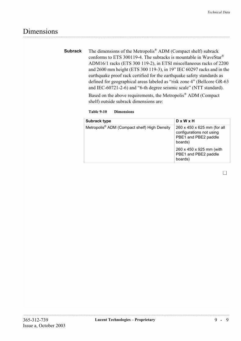
Technical Data
9 - 9Lucent Technologies – Proprietary365-312-739Issue a, October 2003
..............................................................................................................................................................................................................................................................
...............................................................................................................................................................................................................................................................Dimensions
Subrack The dimensions of the Metropolis® ADM (Compact shelf) subrack conforms to ETS 300119-4. The subracks is mountable in WaveStar®
ADM16/1 racks (ETS 300 119-2), in ETSI miscellaneous racks of 2200 and 2600 mm height (ETS 300 119-3), in 19” IEC 60297 racks and in the earthquake proof rack certified for the earthquake safety standards as defined for geographical areas labeled as “risk zone 4” (Bellcore GR-63 and IEC-60721-2-6) and “6-th degree seismic scale” (NTT standard).
Based on the above requirements, the Metropolis® ADM (Compact shelf) outside subrack dimensions are:
Table 9-10 Dimensions
Subrack type D x W x H
Metropolis® ADM (Compact shelf) High Density 260 x 450 x 625 mm (for all configurations not using PBE1 and PBE2 paddle boards)
260 x 450 x 925 mm (with PBE1 and PBE2 paddle boards)

Technical Data
9 - 1 0 Lucent Technologies – Proprietary 365-312-739Issue a, October 2003
..............................................................................................................................................................................................................................................................
...............................................................................................................................................................................................................................................................System weight
The following table depicts the system weight:
Table 9-11 System Weight
System configuration Weight
Metropolis® ADM (Compact shelf) max configuration
less then 70 kg (including internal cables)
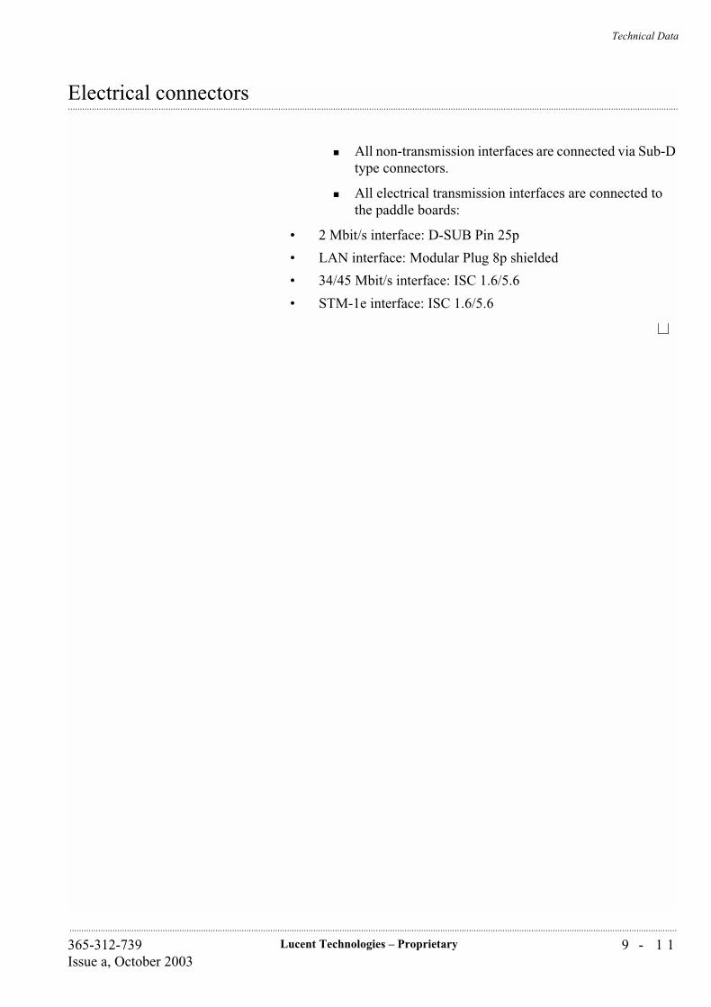
Technical Data
9 - 1 1Lucent Technologies – Proprietary365-312-739Issue a, October 2003
..............................................................................................................................................................................................................................................................
...............................................................................................................................................................................................................................................................Electrical connectors
All non-transmission interfaces are connected via Sub-D type connectors.
All electrical transmission interfaces are connected to the paddle boards:
• 2 Mbit/s interface: D-SUB Pin 25p
• LAN interface: Modular Plug 8p shielded
• 34/45 Mbit/s interface: ISC 1.6/5.6
• STM-1e interface: ISC 1.6/5.6

Technical Data
9 - 1 2 Lucent Technologies – Proprietary 365-312-739Issue a, October 2003
..............................................................................................................................................................................................................................................................
...............................................................................................................................................................................................................................................................Environmental specifications
The following table depicts the environmental specifications:
NC = Non-condensing
The Metropolis® ADM (Compact shelf) fulfills the requirements as specified in ETSI 300 386-1; Public Telecommunication Network Equipment -EMC/ESD requirements as also indicated in the table below.
Table 9-12 Environmental Specifications
Climatic conditionsTemperature range Humidity ETSI Class
Environment -5... +45× C 5 - 90% (NC) 3.1e
Storage -25... +55 C up to 100% (NC) 1.2
Transport -40... +70 C up to 95% (NC) 2.3
Table 9-13 EMC/ESD Requirements
Radiated emission EN 55 022 Class B
Conducted emission:
EN 55 022 Class B
EN 55 022/ETS 300 386-1
CISPR 22 Class B
AC power
DC power
Telecom ports
Electrostatic discharge:
IEC 1000-4-2 level 4
EN 61000-4-2 level 4
Radiated immunity: IEC 1000-4-3 level 3
Electrical fast transient:
IEC 1000-4-4 level 3
IEC 1000-4-4 level 3
IEC 1000-4-4 level 3
AC power
DC power
Telecom ports
Surges:
IEC 1000-4-5 level 4
ETS 300 386-1
AC power
Indoor telecom port
Continuous wave:
IEC 1000-4-6 level 2
IEC 1000-4-6 level 2
IEC 1000-4-6 level 2
AC power
DC power
Telecom ports
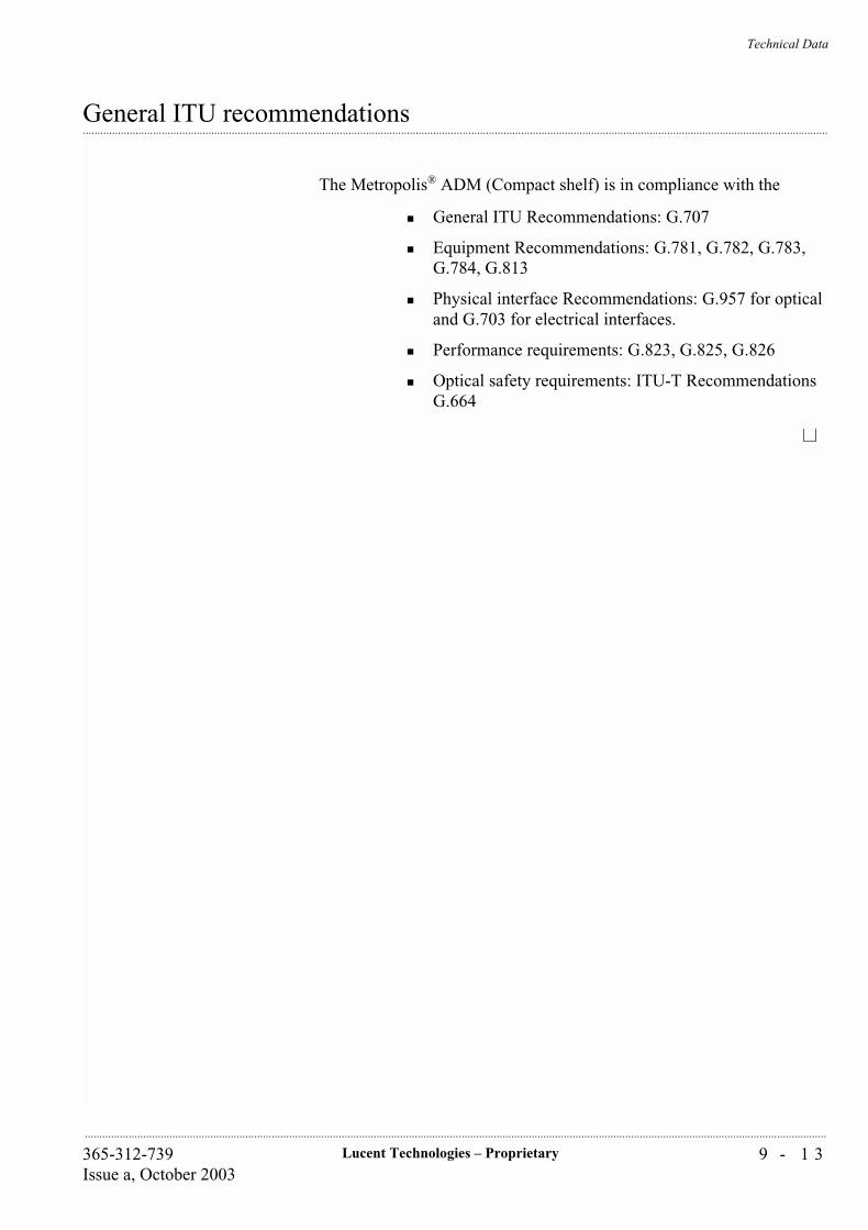
Technical Data
9 - 1 3Lucent Technologies – Proprietary365-312-739Issue a, October 2003
..............................................................................................................................................................................................................................................................
...............................................................................................................................................................................................................................................................General ITU recommendations
The Metropolis® ADM (Compact shelf) is in compliance with the
General ITU Recommendations: G.707
Equipment Recommendations: G.781, G.782, G.783, G.784, G.813
Physical interface Recommendations: G.957 for optical and G.703 for electrical interfaces.
Performance requirements: G.823, G.825, G.826
Optical safety requirements: ITU-T Recommendations G.664
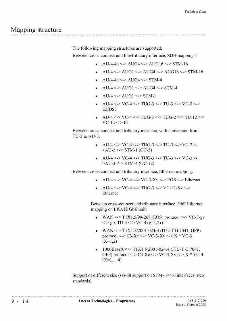
Technical Data
9 - 1 4 Lucent Technologies – Proprietary 365-312-739Issue a, October 2003
..............................................................................................................................................................................................................................................................
...............................................................................................................................................................................................................................................................Mapping structure
The following mapping structures are supported:
Between cross-connect and line/tributary interface, SDH mappings:
AU-4-4c <-> AUG4 <-> AUG16 <-> STM-16
AU-4 <-> AUG1 <-> AUG4 <-> AUG16 <-> STM-16
AU-4-4c <-> AUG4 <-> STM-4
AU-4 <-> AUG1 <-> AUG4 <-> STM-4
AU-4 <-> AUG1 <-> STM-1
AU-4 <-> VC-4 <-> TUG-3 <-> TU-3 <-> VC-3 <-> E3/DS3
AU-4 <-> VC-4 <-> TUG-3 <-> TUG-2 <-> TU-12 <-> VC-12 <-> E1
Between cross-connect and tributary interface, with conversion from TU-3 to AU-3:
AU-4 <-> VC-4 <-> TUG-3 <-> TU-3 <-> VC-3 <->AU-3 <-> STM-1 (OC-3)
AU-4 <-> VC-4 <-> TUG-3 <-> TU-3 <-> VC-3 <->AU-3 <-> STM-4 (OC-12)
Between cross-connect and tributary interface, Ethernet mapping:
AU-4 <-> VC-4 <-> VC-3-Xv <-> EOS <-> Ethernet
AU-4 <-> VC-4 <-> TUG-3 <-> VC-12-Xv <-> Ethernet
Between cross-connect and tributary interface, GbE Ethernet mapping on LKA12 GbE unit:
WAN <-> T1X1.5/99-268 (EOS) protocol <-> VC-3-gv <-> g x TU-3 <-> VC-4 (g=1,2) or
WAN <-> T1X1.5/2001-024r4 (ITU-T G.7041, GFP) protocol <-> C3-Xc <-> VC-3-Xv <-> X * VC-3 (X=1,2)
1000BaseX <-> T1X1.5/2001-024r4 (ITU-T G.7041, GFP) protocol <-> C4-Xc <-> VC-4-Xv <-> X * VC-4 (X=1,.., 4)
Support of different size (ss)-bit support on STM-1/4/16 interfaces (new standards):

Technical Data
9 - 1 5Lucent Technologies – Proprietary365-312-739Issue a, October 2003
..............................................................................................................................................................................................................................................................
In the source direction, the transmitted ss-bits can be provisioned in '10' (SDH mode, default) or '00' (SONET mode)
In the sink direction the incoming ss bits are ignored.
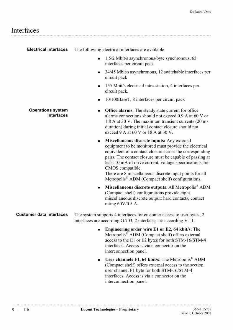
Technical Data
9 - 1 6 Lucent Technologies – Proprietary 365-312-739Issue a, October 2003
..............................................................................................................................................................................................................................................................
...............................................................................................................................................................................................................................................................Interfaces
Electrical interfaces The following electrical interfaces are available:
1.5/2 Mbit/s asynchronous/byte synchronous, 63 interfaces per circuit pack
34/45 Mbit/s asynchronous, 12 switchable interfaces per circuit pack
155 Mbit/s electrical intra-station, 4 interfaces per circuit pack.
10/100BaseT, 8 interfaces per circuit pack
Operations systeminterfaces
Office alarms: The steady state current for office alarms connections should not exceed 0.9 A at 60 V or 1.8 A at 30 V. The maximum transient currents (20 ms duration) during initial contact closure should not exceed 9 A at 60 V or 18 A at 30 V.
Miscellaneous discrete inputs: Any external equipment to be monitored must provide the electrical equivalent of a contact closure across the corresponding pairs. The contact closure must be capable of passing at least 10 mA of drive current, voltage specifications are CMOS compatible.There are 8 miscellaneous discrete input points for all Metropolis® ADM (Compact shelf) configurations.
Miscellaneous discrete outputs: All Metropolis® ADM (Compact shelf) configurations provide eight miscellaneous discrete output: hard contacts, contact rating 60V/0.5 A.
Customer data interfaces The system supports 4 interfaces for customer access to user bytes, 2 interfaces are according G.703, 2 interfaces are according V.11.
Engineering order wire E1 or E2, 64 kbit/s: The Metropolis® ADM (Compact shelf) offers external access to the E1 or E2 bytes for both STM-16/STM-4 interfaces. Access is via a connector on the interconnection panel.
User channels F1, 64 kbit/s: The Metropolis® ADM (Compact shelf) offers external access to the section user channel F1 byte for both STM-16/STM-4 interfaces. Access is via a connector on the interconnection panel.

Technical Data
9 - 1 7Lucent Technologies – Proprietary365-312-739Issue a, October 2003
..............................................................................................................................................................................................................................................................
National Use bytes, RS-NU and MS-NU, 64 kbit/s: The Metropolis® ADM (Compact shelf) offers external access to the section user channel RS-NU and MS-NU byte of STM-1#1 for all STM-1 and STM-16/STM-4 interfaces. Access is via a connector on the interconnection panel.
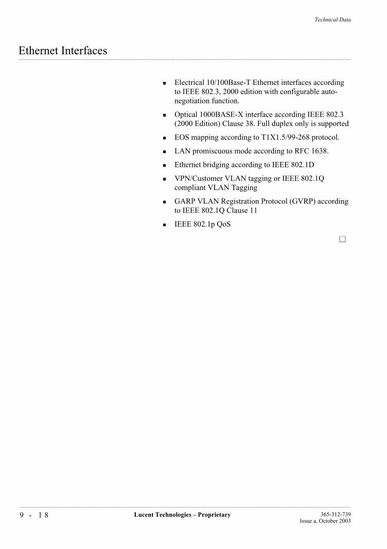
Technical Data
9 - 1 8 Lucent Technologies – Proprietary 365-312-739Issue a, October 2003
..............................................................................................................................................................................................................................................................
...............................................................................................................................................................................................................................................................Ethernet Interfaces
Electrical 10/100Base-T Ethernet interfaces according to IEEE 802.3, 2000 edition with configurable auto-negotiation function.
Optical 1000BASE-X interface according IEEE 802.3 (2000 Edition) Clause 38. Full duplex only is supported
EOS mapping according to T1X1.5/99-268 protocol.
LAN promiscuous mode according to RFC 1638.
Ethernet bridging according to IEEE 802.1D
VPN/Customer VLAN tagging or IEEE 802.1Q compliant VLAN Tagging
GARP VLAN Registration Protocol (GVRP) according to IEEE 802.1Q Clause 11
IEEE 802.1p QoS
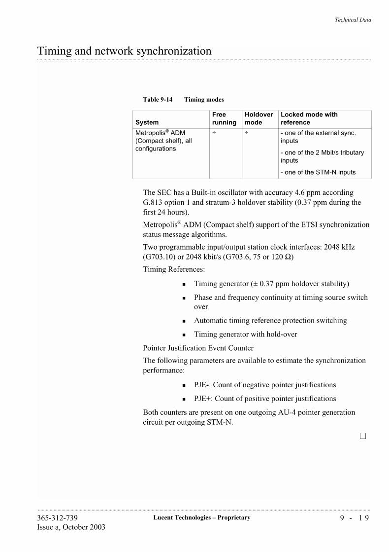
Technical Data
9 - 1 9Lucent Technologies – Proprietary365-312-739Issue a, October 2003
..............................................................................................................................................................................................................................................................
...............................................................................................................................................................................................................................................................Timing and network synchronization
The SEC has a Built-in oscillator with accuracy 4.6 ppm according G.813 option 1 and stratum-3 holdover stability (0.37 ppm during the first 24 hours).
Metropolis® ADM (Compact shelf) support of the ETSI synchronization status message algorithms.
Two programmable input/output station clock interfaces: 2048 kHz (G703.10) or 2048 kbit/s (G703.6, 75 or 120 Ω)
Timing References:
Timing generator (± 0.37 ppm holdover stability)
Phase and frequency continuity at timing source switch over
Automatic timing reference protection switching
Timing generator with hold-over
Pointer Justification Event Counter
The following parameters are available to estimate the synchronization performance:
PJE-: Count of negative pointer justifications
PJE+: Count of positive pointer justifications
Both counters are present on one outgoing AU-4 pointer generation circuit per outgoing STM-N.
Table 9-14 Timing modes
SystemFree running
Holdover mode
Locked mode with reference
Metropolis® ADM (Compact shelf), all configurations
÷ ÷ - one of the external sync. inputs
- one of the 2 Mbit/s tributary inputs
- one of the STM-N inputs
Technical Data
9 - 2 0 Lucent Technologies – Proprietary 365-312-739Issue a, October 2003
..............................................................................................................................................................................................................................................................
...............................................................................................................................................................................................................................................................Transmission performance
Jitter on STM-N interfaces: G.813/G.825
Jitter on PDH interfaces: G.823/G.783
Error performance: G.826
Performance monitoring: G.784/G.826
Technical Data
9 - 2 1Lucent Technologies – Proprietary365-312-739Issue a, October 2003
..............................................................................................................................................................................................................................................................
...............................................................................................................................................................................................................................................................Performance monitoring
The Metropolis® ADM (Compact shelf) has Performance Monitoring capabilities at the following termination points. These points depend on the actual hardware configuration of the Metropolis® ADM (Compact shelf).
Termination points Equipment
VC-12 TTP/CTP for each of the VC-12 termination points
VC-3 TTP/CTP for each of the VC-3 termination points
VC-4 TTP/CTP for each of the VC-4 termination points
RS-16 for each of the 2.488 Gbit/s ports
MS-16 for each of the 2.488 Gbit/s ports
MS-4 for each of the 622 Mbit/s ports
MS-1 for each of the155 Mbit/s ports.
BINS
The following number of bins are available for the Metropolis® ADM (Compact shelf):
Interval History binsTotal History bin storage time
15 minute 164 hours
24 hour 11 day
A threshold can be set for these counts.
The following features are also available for performance monitoring:
Unavailable period registering
Severity settings for alarms on each termination point instance.
Number of Performance Monitoring Points
In releases up to Diamond release 600 performance monitoring points are supported.
From Diamond release onwards 1200 performance monitoring points are supported.
2 Mbit/s non-intrusive monitoring, AIS detection.
Technical Data
9 - 2 2 Lucent Technologies – Proprietary 365-312-739Issue a, October 2003
..............................................................................................................................................................................................................................................................
It is possible to monitor the CRC-4, E-bit and A-bit information in TS0 of any 2 Mbit/s in both directions for performance monitoring purposes for G.704 structured 2 Mbit/s tributaries.
Performance Monitoring for LAN ports 0
On the VC3/VC12 termination points that are connected to a WAN port, the “normal” performance monitoring can be activated. The same counters that apply for VC3/VC12TPs on any other port also apply to the VC3/VC12 TPs on a WAN port.
Apart from this standard SDH PM, a limited amount of counters that are dedicated to LAN/WAN ports are defined. Activation of these counters can be established by setting the LAN port mode to monitored, selecting a LAN port or WAN port as active PM point, and setting the PM point type to LAN or WAN.
The supported dedicated parameters are:
CbS (total number of bytes sent)
CbR (total number of bytes received)
pDe (packets in error dropped)
Note that CbS and CbR are rather traffic monitoring counters than performance monitoring counters, as they give insight in the traffic load in all places in the network. pDe is a real performance monitoring counter as it gives an indication about the performance of the network. Only unidirectional PM is supported for these parameters. Note that because of the difference in units, bytes versus packets, the counters cannot be correlated with each other. Also the counter for dropped packets considers only packets dropped due to errors, and does not include packets dropped due to congestion.
Performance Monitoring on LAN connections (Gigabit Ethernet ports) 0
It is possible to monitor byte and packet related performance parameters on any external Ethernet port and any internal port linked with VC-3/4-Xv channels. The following counters are supported for each port:
· Outgoing number of bytes
Technical Data
9 - 2 3Lucent Technologies – Proprietary365-312-739Issue a, October 2003
..............................................................................................................................................................................................................................................................
...............................................................................................................................................................................................................................................................Network management
The Metropolis® ADM (Compact shelf) can be managed with the following systems:
Fully manageable by Navis® Optical NMS and WaveStar® ITM-SC
Local workstation (ITM-CIT) via RJ45 connections, V.10 (RS-232 compatible)/F-interface
Centralized ITM-CIT alarming. The Metropolis® ADM (Compact shelf) supports a centralized alarm monitoring function on the ITM-CIT.
Access to ECCs via in-station Q-LAN interface, G.773-CLNS1/10-Base-T1 Interfaces.
...................................................................................................................................................................................
1 10BASE-T: Twisted Pair Ethernet
Technical Data
9 - 2 4 Lucent Technologies – Proprietary 365-312-739Issue a, October 2003
..............................................................................................................................................................................................................................................................
...............................................................................................................................................................................................................................................................Bandwidth management
System capacity: 252 x 2 Mbit/s, 48 x E3/DS3, 20 x STM-1, 5 x STM-4, 32 x 10/100BASE-T or 10 x 1000BASE-X
Complete VC-4 cross-connecting
Bi-directional and uni-directional cross-connecting
Higher order and lower order broadcast functionality
Protection access on MS-SPRing
Higher order cross-connect size 64 x 64 VC-4
Lower order cross-connect ranges up to 32 x 32 equivalents, that is 2016 x 2016 VC-12s or 96 x 96 VC-3s.
Technical Data
9 - 2 5Lucent Technologies – Proprietary365-312-739Issue a, October 2003
..............................................................................................................................................................................................................................................................
...............................................................................................................................................................................................................................................................Protection and redundancy
Tributary level redundancy:
• 1: N equipment protection on 1.5 and 2 Mbit/s interface circuit packs (Nmax = 4)
• 1+1 equipment protection on E3/DS3 interface circuit packs
• 1+1 equipment protection on STM-1e interface circuit packs
• 1+1 equipment protection on CORE circuit pack
Non- revertive SNCP/N protection on VC-12/VC-3/VC-4 level
Programmable hold-off times
STM-1 and STM-4 optical interface circuit packs support 1+1 MSP according to G.841 Clause 7.1/ETS 300417-3-1, ANSI T1.105 and Telcordia GR-253-CORE.
STM-16 optical interface circuit packs support 1+1 MSP according to G.841/Clause 7.1 and ETS 300417-3-1.
MS-SPRing in two fiber ring add/drop applications
Selective MS-SPRing. In 2-fiber add/drop ring applications, the VC-4 (-4c)'s in the ring can be protected by the MS-SPRing algorithm according to G.841 and ETS 300417. The user has the option to determine for each VC-4 (-4c) individually, whether or not it participates in the MS-SPRing scheme. If an individual VC-4 (-4c) does not participate then it can be either VC-4 (-4c) SNC protected or not protected at all.
Dual node interworking:
• with drop and continue between SNCP and MS-SPRing on two nodes
• with drop and continue between two MS-SPRings
Maximum of 50 ms. switching time for all protection mechanisms mentioned above
Rapid Spanning Tree Protocol according IEEE 802.1w/D10
LCAS for Ethernet (1000BASE-X “lite”): The implementation is based on Nortel/Lucent contribution to T1X1.5/2000-199r1 (T1X1 T1.105 Section 7.3.4)
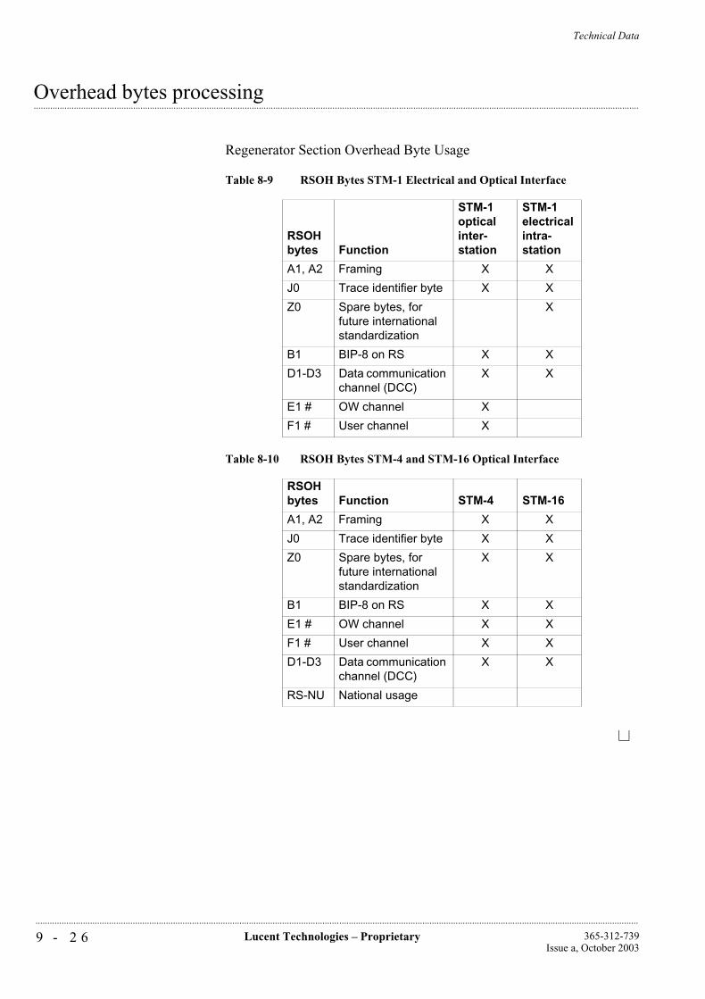
Technical Data
9 - 2 6 Lucent Technologies – Proprietary 365-312-739Issue a, October 2003
..............................................................................................................................................................................................................................................................
...............................................................................................................................................................................................................................................................Overhead bytes processing
Regenerator Section Overhead Byte Usage
Table 8-9 RSOH Bytes STM-1 Electrical and Optical Interface
RSOH bytes Function
STM-1 optical inter-station
STM-1 electrical intra-station
A1, A2 Framing X X
J0 Trace identifier byte X X
Z0 Spare bytes, for future international standardization
X
B1 BIP-8 on RS X X
D1-D3 Data communication channel (DCC)
X X
E1 # OW channel X
F1 # User channel X
Table 8-10 RSOH Bytes STM-4 and STM-16 Optical Interface
RSOH bytes Function STM-4 STM-16
A1, A2 Framing X X
J0 Trace identifier byte X X
Z0 Spare bytes, for future international standardization
X X
B1 BIP-8 on RS X X
E1 # OW channel X X
F1 # User channel X X
D1-D3 Data communication channel (DCC)
X X
RS-NU National usage
Technical Data
9 - 2 7Lucent Technologies – Proprietary365-312-739Issue a, October 2003
..............................................................................................................................................................................................................................................................
...............................................................................................................................................................................................................................................................Metropolis® ADM (Compact shelf) Customer Documentation
General Structure The SDH customer documentation has a task-oriented approach, based on the task-analysis as performed during the development and implementation of the systems. This leads to different documents each intended to perform a specific task, closely related to the deployment phases of a telecommunications network. These phases are to plan, install, test and maintain the network and its elements.
As a rule, a documentation set covers one particular system (-version) or a compilation of closely related members of a system family. Within the system documentation, the documentation on cooperating sub-systems -if any- is integrated in a modular fashion. However, when systems are part of a certain network application network oriented documentation is made. Because of this, a significant difference is made between network element oriented and network oriented documentation, based on the specific definitions of a network element and a network.
Manual organization All manuals are provided with:
front pages, which gives general information about the guide, the overall contents of the guide, how to use it, relations with other documents and conventions and validity statements.
a number of chapters, clearly separated by numbered tabs. Each chapter has its own table of contents and contains a general introduction explaining what is described and how it is organized into sections. Together with the overall contents of the guide incorporated in the front pages readers can quickly select the information of their interests and/or needs.
a chapter called “Acronyms and Abbreviations” that are used within the text of the guide.
a chapter called Glossary, which lists and defines special terms that are used within the text of the guide.
an Index, which provides easy access to important terms and words used within the text of the guide, by means of page number reference.
However, customer documentation is subject to continuous improvement and therefore the manual organization can change on details, the overall subject coverage remains the same or will increase.
Network Element SpecificDocuments
The network element specific guides are system oriented documents on network element level, focusing on hardware and (SDH-)CIT and are shipped to the network element sites only. Types of guides are:
Technical Data
9 - 2 8 Lucent Technologies – Proprietary 365-312-739Issue a, October 2003
..............................................................................................................................................................................................................................................................
Cable Layout Manual (CLM)
Network Element Installation Guide (IG)
Cable Layout Manual (CLM) The Cable Layout Manual describes all mounting and cabling of a specific network element. It forms an important addition to all Physical mounting instructions, that is to mount racks and subracks.
The manual contains functional descriptions of the mechanical part of the subrack as well as technical data, subrack dimensions and instructions how to mount the subrack. Besides, information is given about cable links and arrangement of connectors on the interconnection panel of the subrack.
This manual is intended for installation technicians responsible for mounting the subrack and connecting the interfaces.
Network ElementInstallation Guide (NIG)
The Network Element Installation Guide contains all information to locally install and start-up an network element, hardware-wise and software-wise to a condition, in which it can be used into an SDH network for the first time.
Installation of hardware comprises the complete procedures necessary to set hardware straps on units, to equip the subracks with units, to provision the system software of all network element types to customer specific configurations and to test the system locally.
Installation of software comprises the complete procedures necessary to install and activate software on the workstation, necessary for further configuration and maintenance of the network element.
After installation, the network element is ready for installation in a network and connection to a management system for further configuration, e.g. provisioning timing, transmission paths, etc.
This guide is intended for installation and testing personnel that takes care of deploying the network elements in the network. However, this manual is also useful for those involved in system projecting and planning tasks or network engineering and administrative tasks.
Network ElementMaintenance Guide
The Network Element Maintenance Guide contains all information necessary for local maintenance activities of a network element with the use of a Craft Interface Terminal (CIT), assumed that the network element has functioned properly and no malfunctions are detected so far.
This guide is intended for personnel that takes care of the daily, local maintenance activities on the network element.
Available documents
User Operation Guide (UOG)
Alarm Messages and Trouble Clearing Guide (AMTCG).
Technical Data
9 - 2 9Lucent Technologies – Proprietary365-312-739Issue a, October 2003
..............................................................................................................................................................................................................................................................
Release notes In addition to the Customer Documents as described before, Release Notes are shipped with the product to all sites where equipment is installed. The Release Notes describe general additional guidelines, important things to know, unpredictable behavior and last-minute changes to the parts of the SDH network at delivery time. The Release Notes are intended to guide the user dealing with all operations required during network deployment (installation, testing, maintenance and upgrading) to make optimal use of procedures described in the Customer Documentation. References are made in the Release Notes to the relevant sections, chapters and paragraphs in the Customer Documentation, where applicable.
Related Documentationwith focus on Element and
Network Management
Subnetwork-Controller Installation GuideInformation on installation of the WaveStar® ITM-SC Subnetwork Controller.
Subnetwork Provisioning GuideInformation on configuring or reconfiguring the WaveStar® Network Elements, setting cross-connects and synchronizing your network by using the WaveStar® ITM-SC Subnetwork Controller.
Subnetwork Maintenance GuideInformation on maintaining the WaveStar® Network Elements by using the WaveStar® ITM-SC Subnetwork Controller.
Subnetwork-Controller Administration GuideInformation on how to install and start-up software on the WaveStar® ITM-SC Management System, to give users access to the WaveStar® ITM-SC Subnetwork Controller and to backup and restore databases.
On-line Documentation On-Line Documentation is created from the information available within the User Documentation.With the software package used on the WaveStar® ITM-SC, called HyperHelp viewer, the files can be viewed and printed, navigated- and searched through. In the near future the on-line documentation can be extended to more context-sensitive information, which is in fact an addition to the help text functionality currently being implemented within the WaveStar® ITM-SC help files.

Technical Data
9 - 3 0 Lucent Technologies – Proprietary 365-312-739Issue a, October 2003
..............................................................................................................................................................................................................................................................

1 0 - 1Lucent Technologies – Proprietary365-312-739Issue a, October 2003
..............................................................................................................................................................................................................................................................
10 Quality and reliability
...............................................................................................................................................................................................................................................................Overview
This section describes Lucent Technologies’ commitment to quality and reliability and how quality is ensured.

Quality and reliability
1 0 - 2 Lucent Technologies – Proprietary 365-312-739Issue a, October 2003
..............................................................................................................................................................................................................................................................
...............................................................................................................................................................................................................................................................Lucent Technologies’ commitment to quality and reliability
Overview Lucent Technologies is extremely committed to providing our customers with products of the highest level of quality and reliability in the industry. Metropolis® ADM (Compact shelf) is a prime example of this commitment.
In line with this policy, all major transmission facilities in the USA, Europe and China are ISO-9000 certified. In line with the above, Lucent Technologies’ policy statement in this respect is as follows.
Quality policy Lucent Technologies is committed to achieving sustained business excellence by integrating quality principles and methods into all we do at every level of our company to
• Anticipate and meet customer needs and exceed their expectations, every time
• Relentlessly improve how we work - to deliver the world’s best and most innovative communications solutions - faster and more
Reliability in the productlife-cycle
Each stage of the life cycle of Metropolis® ADM (Compact shelf) relies on people and processes that contribute to the highest product quality and reliability possible. The reliability of a product begins at the earliest planning stage and continues into
• Product architecture
• Design and simulation
• Documentation
• Prototype testing during development
• Design change control
• Manufacturing and product testing (including 100% screening)
• Product quality assurance
• Product field performance
• Product field return management
• The R&D community of Lucent Technologies is certified by ISO 9001
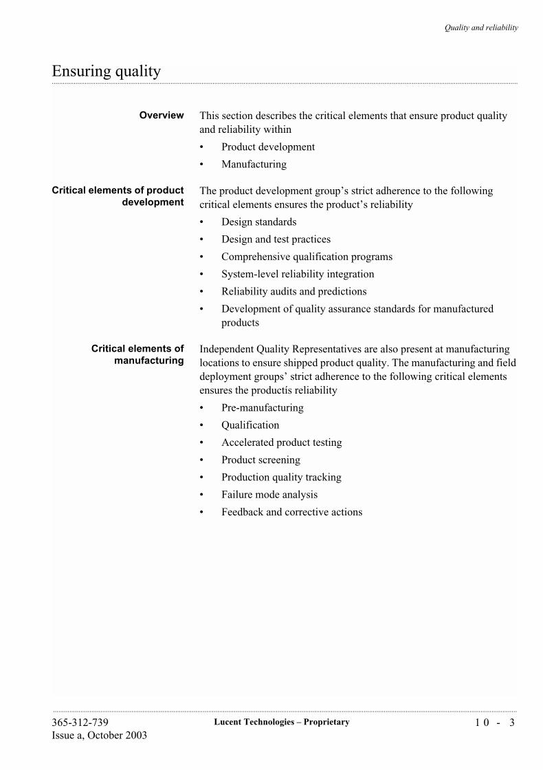
Quality and reliability
1 0 - 3Lucent Technologies – Proprietary365-312-739Issue a, October 2003
..............................................................................................................................................................................................................................................................
...............................................................................................................................................................................................................................................................Ensuring quality
Overview This section describes the critical elements that ensure product quality and reliability within
• Product development
• Manufacturing
Critical elements of productdevelopment
The product development group’s strict adherence to the following critical elements ensures the product’s reliability
• Design standards
• Design and test practices
• Comprehensive qualification programs
• System-level reliability integration
• Reliability audits and predictions
• Development of quality assurance standards for manufactured products
Critical elements ofmanufacturing
Independent Quality Representatives are also present at manufacturing locations to ensure shipped product quality. The manufacturing and field deployment groups’ strict adherence to the following critical elements ensures the productís reliability
• Pre-manufacturing
• Qualification
• Accelerated product testing
• Product screening
• Production quality tracking
• Failure mode analysis
• Feedback and corrective actions

Quality and reliability
1 0 - 4 Lucent Technologies – Proprietary 365-312-739Issue a, October 2003
..............................................................................................................................................................................................................................................................
...............................................................................................................................................................................................................................................................Environmental aspects
EH&S management Lucent Technologies has elected to move forward with ISO 14001 for environmental management systems for its operations and facilities. In fact, as part of our environmental, health, and safety goals, we have committed to have in place EH&S management systems by the year 2003 that are based on recognized standards such as ISO 14001 for at least 95% of our products, services, operations and facilities.
At the end of 1998, 23 Lucent facilities, operations, and services were awarded ISO 14001 certification by third-party auditors. The two manufacturing facilities of the optical networking group (the business unit that makes the Metropolis® ADM (Compact shelf)) had already received ISO 14001 certification in September 1998.
Lucent’s environmental commitment is demonstrated through its structure of environmental and health and safety personnel throughout all levels of the company. A company officer supports the setting of corporate goals and policies, and a Global Environmental Health and Safety Vice President oversees environmental aspects for operations worldwide.
In addition, each of the business units (including the optical networking group, the unit that manufactures the Metropolis® ADM (Compact shelf)) has its own responsible environment and safety officer. Finally, each facility has environmental managers who are for compliance with and the implementation of environmental management systems such as ISO 14001.
Quality and reliability
1 0 - 5Lucent Technologies – Proprietary365-312-739Issue a, October 2003
..............................................................................................................................................................................................................................................................
...............................................................................................................................................................................................................................................................Conformity statements
CE conformity Hereby, Lucent Technologies declares that the Lucent Technologies product
Metropolis® ADM (Compact shelf), Release 3.2
is in compliance with the essential requirements and other relevant provisions of the following Directive:
Directive 1999/5/EC of 9 March 1999 on Radio and Telecommunication Terminal Equipment of the European Parliament and of the Council
is tested and conforms with the essential requirements for protection of health and the safety of the user and any other person and Electromagnetic Compatibility. Conformity is indicated by the CE mark affixed to the product. For more information regarding CE marking and Declaration of Conformity (DoC), please contact your local Lucent Technologies Customer Service Organization.
This product is in conformity with Article 3, Paragraph 3 of the R&TTE Directive and interworks in networks with other equipment connected to the optical telecommunication network.
Conformance with specifications of optical interfaces is granted as stated in the Official Journal of the European Union
Compliance Statement inother European Languages
English
Hereby, Lucent Technologies, declares that this Metropolis® ADM (Compact shelf) is in compliance with the essential requirements and other relevant provisions of Directive 1999/5/EC.
Finnish
Lucent Technologies vakuuttaa täten että Metropolis® ADM (Compact shelf) tyyppinen laite on direktiivin 1999/5/EY oleellisten vaatimusten ja sitä koskevien direktiivin muiden ehtojen mukainen.
Dutch
Bij deze verklaart Lucent Technologies dat deze Metropolis® ADM (Compact shelf) voldoet aan de essentiële eisen en aan de overige relevante bepalingen van Richtlijn 1999/5/EC.
French
Par la présente, Lucent Technologies déclare que ce Metropolis® ADM (Compact shelf) est conforme aux exigences essentielles et aux autres dispositions de la directive 1999/5/CE qui lui sont applicables.
Swedish
Quality and reliability
1 0 - 6 Lucent Technologies – Proprietary 365-312-739Issue a, October 2003
..............................................................................................................................................................................................................................................................
Härmed intygar Lucent Technologies att denna Metropolis® ADM (Compact shelf) står I överensstämmelse med de väsentliga egenskapskrav och övriga relevanta bestämmelser som framgår av direktiv 1999/5/EG.
Danish
Undertegnede Lucent Technologies erklærer herved, at følgende udstyr Metropolis® ADM (Compact shelf) overholder de væsentlige krav og øvrige relevante krav i direktiv 1999/5/EF
German
Hiermit erklärt Lucent Technologies die Übereinstimmung des Gerätes Metropolis® ADM (Compact shelf) mit den grundlegenden Anforderungen und den anderen relevanten Festlegungen der Richtlinie 1999/5/EG.
Greek
ΜΕ ΤΗΝ ΠΑΡΟΨΣΑ Lucent Technologies ∆ΗΛΩΝΕΙ ΟΤΙ Metropolis® ADM (Compact shelf) ΣΨΜΜΟΡΦΩΝΕΤΑΙ ΠΡΟΣ ΤΙΣ ΟΨΣΙΩ∆ΕΙΣ ΑΠΑΙΤΗΣΕΙΣ ΚΑΙ ΤΙΣ ΛΟΙΠΕΣ ΣΧΕΤΙΚΕΣ ∆ΙΑΤΑΞΕΙΣ ΤΗΣ Ο∆ΗΓΙΑΣ 1999/5/EK
Italian
Con la presente Lucent Technologies dichiara che questo Metropolis® ADM (Compact shelf) è conforme ai requisiti essenziali ed alle altre disposizioni pertinenti stabilite dalla direttiva 1999/5/CE.
Spanish
Por medio de la presente Lucent Technologies declara que el Metropolis® ADM (Compact shelf) cumple con los requisitos esenciales y cualesquiera otras disposiciones aplicables o exigibles de la Directiva 1999/5/CE
Portuguese
Lucent Technologies declara que este Metropolis® ADM (Compact shelf) está conforme com os requisitos essenciais e outras provisões da Directiva 1999/5/CE.

Quality and reliability
1 0 - 7Lucent Technologies – Proprietary365-312-739Issue a, October 2003
..............................................................................................................................................................................................................................................................
CE conformity declaration
Figure 8-2 CE conformity declaration

Quality and reliability
1 0 - 8 Lucent Technologies – Proprietary 365-312-739Issue a, October 2003
..............................................................................................................................................................................................................................................................
Technical documentation The technical documentation as required by the Conformity Assessment procedure is kept at Lucent Technologies location which is responsible for this product. For more information please contact your local Lucent Technologies representative.

Quality and reliability
1 0 - 9Lucent Technologies – Proprietary365-312-739Issue a, October 2003
..............................................................................................................................................................................................................................................................
...............................................................................................................................................................................................................................................................Reliability specifications
Overview This section describes how reliability is specified.

Quality and reliability
1 0 - 1 0 Lucent Technologies – Proprietary 365-312-739Issue a, October 2003
..............................................................................................................................................................................................................................................................
...............................................................................................................................................................................................................................................................General specifications
Overview This section provides general reliability specifications for Metropolis® ADM (Compact shelf).
Mean time between failures The mean time between failures (MTBF) for the whole Metropolis® ADM (Compact shelf) is 2.5 years.
Mean time to repair The mean time to repair for Metropolis® ADM (Compact shelf) is assumed to be 2 hours. This figure includes dispatch, diagnostic, and repair time.
Infant mortality factor Note: The steady state failure rate is equal to the failure rate of the system.
The number of failures that a product experiences during the first year of service after turn-up may be greater than the number of subsequent annual steady state failures. This is the early life or infant mortality period. The ratio of the first year failure rate to the steady state failure rate is termed the infant mortality factor (IMF).
The estimation of the Metropolis® ADM (Compact shelf) circuit pack reliability is based on an infant mortality factor (IMF) smaller than 2.5. That means the first year failure rate (or infant mortality rate [IMR]) is assumed to be < 2.5 times the steady state failure rate.
Product design life The product design life for Metropolis® ADM (Compact shelf) is 15 years except for the fan units. The fan unit design life is 7 years.
Maintainabilityspecifications
The air filter, located below the subrack, must be replaced or cleaned under regular conditions once every 3 to 6 months to ensure proper cooling.
Quality and reliability
1 0 - 1 1Lucent Technologies – Proprietary365-312-739Issue a, October 2003
..............................................................................................................................................................................................................................................................
...............................................................................................................................................................................................................................................................Reliability program
Introduction Reliability is a key ingredient of products life cycle from the earliest planning stage. Major occurrences at the start of the project involve modeling of system reliability. During the design and development stage, reliability predictions, qualification and selection of components, definition of quality assurance standards and prototyping of critical system areas ensured built-in reliability. Manufacturing and field deployment, techniques such as pre-manufacturing, qualification, tracking of production quality, burn-in tests, failure mode analysis and feedback and correction further enhance the ongoing reliability of the Metropolis® ADM (Compact shelf).
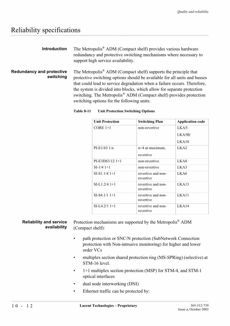
Quality and reliability
1 0 - 1 2 Lucent Technologies – Proprietary 365-312-739Issue a, October 2003
..............................................................................................................................................................................................................................................................
...............................................................................................................................................................................................................................................................Reliability specifications
Introduction The Metropolis® ADM (Compact shelf) provides various hardware redundancy and protective switching mechanisms where necessary to support high service availability.
Redundancy and protectiveswitching
The Metropolis® ADM (Compact shelf) supports the principle that protective switching options should be available for all units and busses that could lead to service degradation when a failure occurs. Therefore, the system is divided into blocks, which allow for separate protection switching. The Metropolis® ADM (Compact shelf) provides protection switching options for the following units:
Table 8-11 Unit Protection Switching Options
Reliability and serviceavailability
Protection mechanisms are supported by the Metropolis® ADM (Compact shelf):
• path protection or SNC/N protection (SubNetwork Connection protection with Non-intrusive monitoring) for higher and lower order VCs
• multiplex section shared protection ring (MS-SPRing) (selective) at STM-16 level.
• 1+1 multiplex section protection (MSP) for STM-4, and STM-1 optical interfaces
• dual node interworking (DNI)
• Ethernet traffic can be protected by:
Unit Protection Switching Plan Application code
CORE 1+1 non-revertive LKA5/
LKA5B/
LKA10
PI-E1/63 1:n n=4 at maximum,
revertive
LKA2
PI-E3DS3/12 1+1 non-revertive LKA8
SI-1/4 1+1 non-revertive LKA3
SI-S1.1/4 1+1 revertive and non-revertive
LKA6
SI-L1.2/4 1+1 revertive and non-revertive
LKA13
SI-S4.1/1 1+1 revertive and non-revertive
LKA11
SI-L4.2/1 1+1 revertive and non-revertive
LKA14

Quality and reliability
1 0 - 1 3Lucent Technologies – Proprietary365-312-739Issue a, October 2003
..............................................................................................................................................................................................................................................................
• spanning tree protocol
• link capacity adjustment scheme (LCAS)
Metropolis® ADM(Compact shelf) circuit-
pack fit rates
The following table gives an overview of the circuit packs fit rates.
Table 8-12 Circuit Pack FIT Rates
Item Unit Name FIT rateApplication Code
Common SC 4424 LKA1B
Standalone CC CC/PT-64/32 Not available LKA15
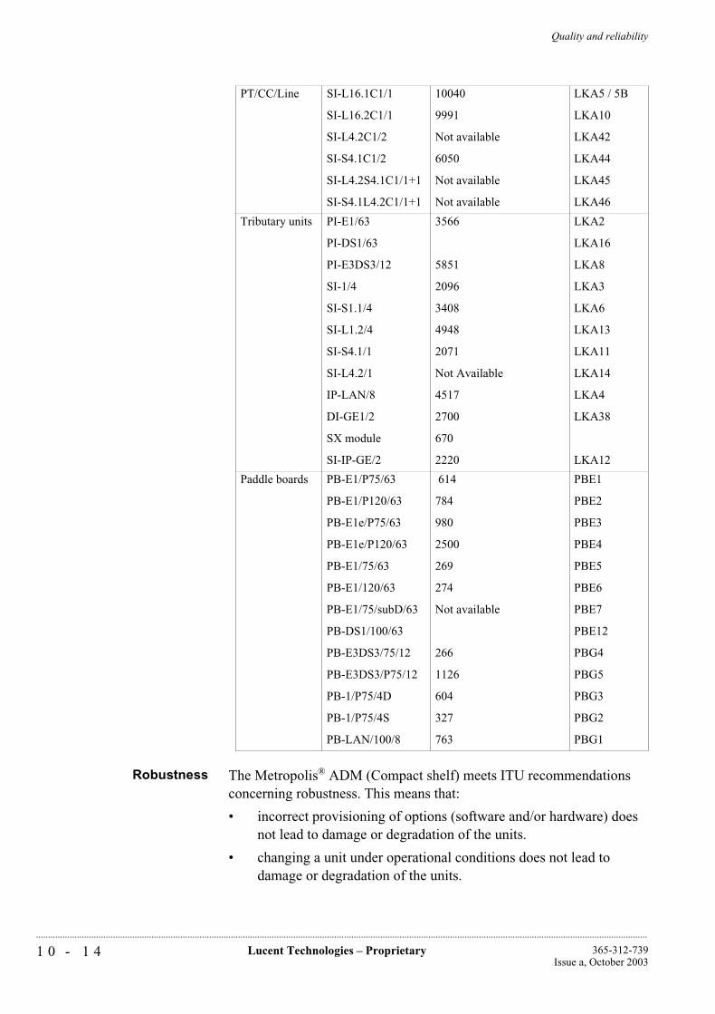
Quality and reliability
1 0 - 1 4 Lucent Technologies – Proprietary 365-312-739Issue a, October 2003
..............................................................................................................................................................................................................................................................
Robustness The Metropolis® ADM (Compact shelf) meets ITU recommendations concerning robustness. This means that:
• incorrect provisioning of options (software and/or hardware) does not lead to damage or degradation of the units.
• changing a unit under operational conditions does not lead to damage or degradation of the units.
PT/CC/Line SI-L16.1C1/1
SI-L16.2C1/1
SI-L4.2C1/2
SI-S4.1C1/2
SI-L4.2S4.1C1/1+1
SI-S4.1L4.2C1/1+1
10040
9991
Not available
6050
Not available
Not available
LKA5 / 5B
LKA10
LKA42
LKA44
LKA45
LKA46
Tributary units PI-E1/63
PI-DS1/63
PI-E3DS3/12
SI-1/4
SI-S1.1/4
SI-L1.2/4
SI-S4.1/1
SI-L4.2/1
IP-LAN/8
DI-GE1/2
SX module
SI-IP-GE/2
3566
5851
2096
3408
4948
2071
Not Available
4517
2700
670
2220
LKA2
LKA16
LKA8
LKA3
LKA6
LKA13
LKA11
LKA14
LKA4
LKA38
LKA12
Paddle boards PB-E1/P75/63
PB-E1/P120/63
PB-E1e/P75/63
PB-E1e/P120/63
PB-E1/75/63
PB-E1/120/63
PB-E1/75/subD/63
PB-DS1/100/63
PB-E3DS3/75/12
PB-E3DS3/P75/12
PB-1/P75/4D
PB-1/P75/4S
PB-LAN/100/8
614
784
980
2500
269
274
Not available
266
1126
604
327
763
PBE1
PBE2
PBE3
PBE4
PBE5
PBE6
PBE7
PBE12
PBG4
PBG5
PBG3
PBG2
PBG1

Quality and reliability
1 0 - 1 5Lucent Technologies – Proprietary365-312-739Issue a, October 2003
..............................................................................................................................................................................................................................................................
• when a non-traffic-carrying unit is plugged in or removed, no transmission errors will be caused in the system.
• when a traffic-carrying unit is plugged in or removed, no errors will be caused in any traffic not directly related to that unit.
• short-circuiting of any electrical inputs and outputs (except the Primary Power feeds) on user accessible connectors will not cause any damage or degradation.
• there will be no degradation in the equipment performance when the subrack and each card are individually subjected to a “percussio test”.
• insertion of the incorrect card in to any slot will not cause damage to card or slot.
• removal of any card will not inhibit the reporting of alarms to the station-alarm scheme or to the management system. When the SC card is removed, only the System Controller Removed alarm loop will close to indicate this situation.
• When a non-traffic-carrying unit is plugged in or removed, no errors will be caused in the transmission of the system.
• When a traffic-carrying unit is plugged in or removed, no errors will be caused in any traffic not directly related to that unit.
• Short-circuiting of any electrical inputs and outputs (except thePrimary Power feeds) on user accessible connectors will not cause any damage or degradation.
• There will be no degradation in the equipment performance when the subrack and each card are individually subjected to a percussio test.
• Insertion of the incorrect card in to any slot will not cause damage to card or slot.
• Removal of any card (including SC) will not inhibit alarms reporting to the station alarm scheme or management system.

Lucent Technologies – ProprietarySee notice on first page
365-312-739Issue a, October 2003
...........................................................................................................................................................................................................................................................
Quality and reliability
1 1 - 1Lucent Technologies – Proprietary365-312-739Issue a, October 2003
..............................................................................................................................................................................................................................................................
11 Product support
...............................................................................................................................................................................................................................................................Overview
This chapter provides information about the support for the Metropolis® ADM (Compact shelf).
Product support
1 1 - 2 Lucent Technologies – Proprietary 365-312-739Issue a, October 2003
..............................................................................................................................................................................................................................................................
...............................................................................................................................................................................................................................................................Installation Services
Overview This section describes the installation services available to support Metropolis® ADM (Compact shelf).
Lucent Technologies offers Installation Services focused on providing the technical support and resources needed to efficiently and cost-effectively install your network equipment. Lucent Technologies Installation Services provide unparalleled network implementation expertise to help install your wire line and wireless networks. We use state-of-the-art tools and technology, and highly skilled technicians to install your equipment and help to ensure the timely and complete implementation of your network solution. By relying on our installation experts, we can rapidly build or expand your network, help manage the complexity of implementing new technologies, reduce operational costs, and help improve your competitive position by enabling your staff to focus on the core aspects of your business rather than focusing on infrastructure details.
Description Within Lucent Technologiesí overall Installation Services portfolio, Basic Equipment Installation and Site Supplemental Installation are the two services most closely linked to the initial deployment of Lucent Technologies’ Metropolis® ADM (Compact shelf) product into your network.
Basic Equipment Installation
Provides the resources, experience and tools necessary to install the Metropolis® ADM (Compact shelf) product into your network. We assemble, cable and wire, and test the Metropolis® ADM (Compact shelf), helping to ensure it is fully functioning as engineered and specified.
Site Supplemental Installation
Enhances the Basic Equipment Installation service by performing supplemental work that is unique to your specific site location, configuration, or working requirements. Includes installation of material other than the main footprint product (such as earthquake bracing); provision of services unique to your site (such as, hauling and hoisting, multi-floor cabling, rental and local purchases) or as may be required by your operations (such as, overtime to meet your compressed schedules, night work requested by you, abnormal travel expenses, abnormal transportation or warehousing); and any other additional effort or charges associated with your environment.
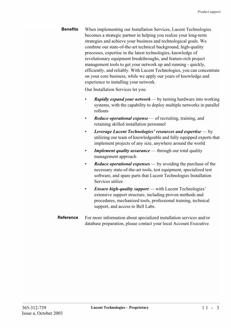
Product support
1 1 - 3Lucent Technologies – Proprietary365-312-739Issue a, October 2003
..............................................................................................................................................................................................................................................................
Benefits When implementing our Installation Services, Lucent Technologies becomes a strategic partner in helping you realize your long-term strategies and achieve your business and technological goals. We combine our state-of-the-art technical background, high-quality processes, expertise in the latest technologies, knowledge of revolutionary equipment breakthroughs, and feature-rich project management tools to get your network up and running - quickly, efficiently, and reliably. With Lucent Technologies, you can concentrate on your core business, while we apply our years of knowledge and experience to installing your network.
Our Installation Services let you:
• Rapidly expand your network — by turning hardware into working systems, with the capability to deploy multiple networks in parallel rollouts
• Reduce operational expense — of recruiting, training, and retaining skilled installation personnel
• Leverage Lucent Technologies’ resources and expertise — by utilizing our team of knowledgeable and fully equipped experts that implement projects of any size, anywhere around the world
• Implement quality assurance — through our total quality management approach
• Reduce operational expenses — by avoiding the purchase of the necessary state-of-the-art tools, test equipment, specialized test software, and spare parts that Lucent Technologies Installation Services utilize
• Ensure high-quality support — with Lucent Technologies’ extensive support structure, including proven methods and procedures, mechanized tools, professional training, technical support, and access to Bell Labs.
Reference For more information about specialized installation services and/or database preparation, please contact your local Account Executive.
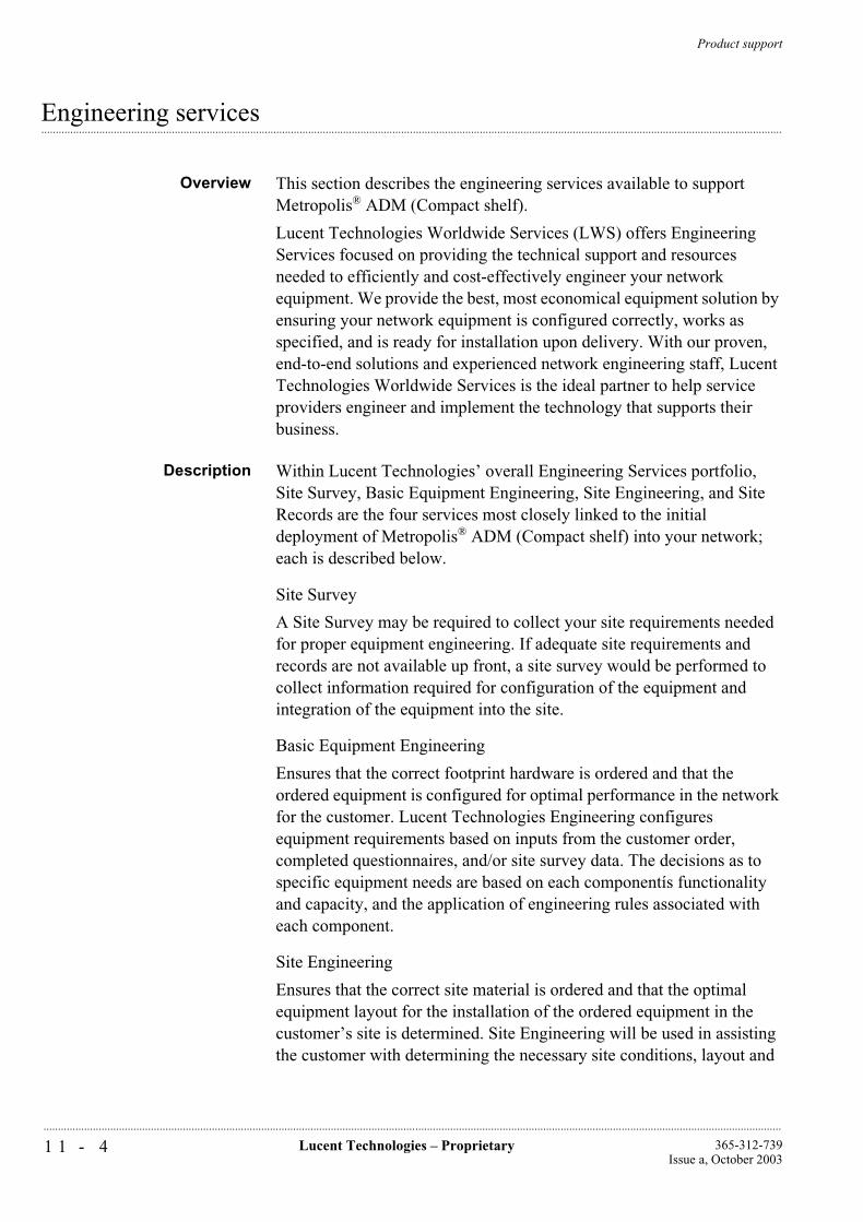
Product support
1 1 - 4 Lucent Technologies – Proprietary 365-312-739Issue a, October 2003
..............................................................................................................................................................................................................................................................
...............................................................................................................................................................................................................................................................Engineering services
Overview This section describes the engineering services available to support Metropolis® ADM (Compact shelf).
Lucent Technologies Worldwide Services (LWS) offers Engineering Services focused on providing the technical support and resources needed to efficiently and cost-effectively engineer your network equipment. We provide the best, most economical equipment solution by ensuring your network equipment is configured correctly, works as specified, and is ready for installation upon delivery. With our proven, end-to-end solutions and experienced network engineering staff, Lucent Technologies Worldwide Services is the ideal partner to help service providers engineer and implement the technology that supports their business.
Description Within Lucent Technologies’ overall Engineering Services portfolio, Site Survey, Basic Equipment Engineering, Site Engineering, and Site Records are the four services most closely linked to the initial deployment of Metropolis® ADM (Compact shelf) into your network; each is described below.
Site Survey
A Site Survey may be required to collect your site requirements needed for proper equipment engineering. If adequate site requirements and records are not available up front, a site survey would be performed to collect information required for configuration of the equipment and integration of the equipment into the site.
Basic Equipment Engineering
Ensures that the correct footprint hardware is ordered and that the ordered equipment is configured for optimal performance in the network for the customer. Lucent Technologies Engineering configures equipment requirements based on inputs from the customer order, completed questionnaires, and/or site survey data. The decisions as to specific equipment needs are based on each componentís functionality and capacity, and the application of engineering rules associated with each component.
Site Engineering
Ensures that the correct site material is ordered and that the optimal equipment layout for the installation of the ordered equipment in the customer’s site is determined. Site Engineering will be used in assisting the customer with determining the necessary site conditions, layout and

Product support
1 1 - 5Lucent Technologies – Proprietary365-312-739Issue a, October 2003
..............................................................................................................................................................................................................................................................
equipment required to properly install/integrate the footprint hardware components into a specific location.
Site Records
Site Records Service provides detailed record keeping which accurately documents the physical placement and configuration of specified customer equipment. Depending on the customer request, this can involve the initial creation of site records, updating of existing records, or ongoing maintenance of the customer’s records.
Benefits When implementing our Engineering Services, Lucent Technologies becomes a strategic partner in helping you realize your long-term strategies and achieve your business and technological goals. Our Engineering Services portfolio delivers quick, responsive support, with state-of-the-art tools, top technicians and end-to-end services to help you engineer an optimal network solution. Whether you are looking to outsource your total engineering effort or simply supplement basic coverage gaps, our portfolio of services provides the flexible level of support you need. With Lucent Technologies, you can concentrate on your core business while we apply our years of knowledge and experience in engineering your equipment solutions.
Our Engineering Services let you:
• Rapidly expand your network — by turning products into working systems, with the capability to deploy multiple networks in parallel rollouts
• Reduce costs — by determining the most cost-effective network configuration and optimal use of office space when planning and providing an equipment solution
• Reduce operational expense — of recruiting, training, and retaining skilled engineering personnel
• Leverage Lucent Technologiesí resources and expertise — by utilizing our team of knowledgeable and fully equipped experts that can plan, design, and implement projects of any size, anywhere around the world
• Implement quality assurance — through our total quality management approach and use of ISO-certified processes
• Provide one-stop shopping — with a globally deployed engineering workforce, saving the time, delays and coordination challenges of dealing with multiple equipment vendors and service providers
• Keep pace with rapidly changing technology — by supporting the latest technologies and equipment breakthroughs, including Lucent Technologies’ and other vendor’s products

Product support
1 1 - 6 Lucent Technologies – Proprietary 365-312-739Issue a, October 2003
..............................................................................................................................................................................................................................................................
• Ensure high-quality support — with Lucent Technologies’ extensive support structure, including proven methods and procedures, mechanized tools, professional training, technical support, and access to Bell Labs
• Maintain and track vital office records — keep track of equipment locations and connections.
Reference For more information about specialized engineering services, engineering consultations, and/or database preparation, please contact your local Account Executive.
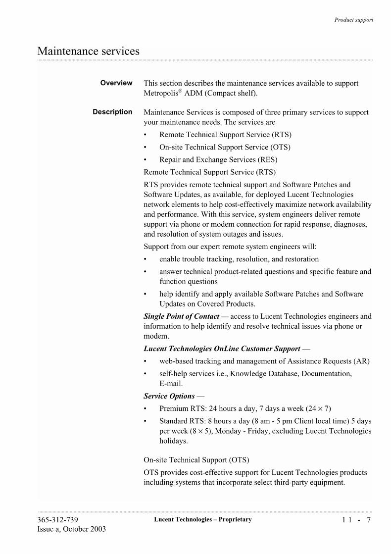
Product support
1 1 - 7Lucent Technologies – Proprietary365-312-739Issue a, October 2003
..............................................................................................................................................................................................................................................................
...............................................................................................................................................................................................................................................................Maintenance services
Overview This section describes the maintenance services available to support Metropolis® ADM (Compact shelf).
Description Maintenance Services is composed of three primary services to support your maintenance needs. The services are
• Remote Technical Support Service (RTS)
• On-site Technical Support Service (OTS)
• Repair and Exchange Services (RES)
Remote Technical Support Service (RTS)
RTS provides remote technical support and Software Patches and Software Updates, as available, for deployed Lucent Technologies network elements to help cost-effectively maximize network availability and performance. With this service, system engineers deliver remote support via phone or modem connection for rapid response, diagnoses, and resolution of system outages and issues.
Support from our expert remote system engineers will:
• enable trouble tracking, resolution, and restoration
• answer technical product-related questions and specific feature and function questions
• help identify and apply available Software Patches and Software Updates on Covered Products.
Single Point of Contact — access to Lucent Technologies engineers and information to help identify and resolve technical issues via phone or modem.
Lucent Technologies OnLine Customer Support —
• web-based tracking and management of Assistance Requests (AR)
• self-help services i.e., Knowledge Database, Documentation,E-mail.
Service Options —
• Premium RTS: 24 hours a day, 7 days a week (24 × 7)
• Standard RTS: 8 hours a day (8 am - 5 pm Client local time) 5 days per week (8 × 5), Monday - Friday, excluding Lucent Technologies holidays.
On-site Technical Support (OTS)
OTS provides cost-effective support for Lucent Technologies products including systems that incorporate select third-party equipment.

Product support
1 1 - 8 Lucent Technologies – Proprietary 365-312-739Issue a, October 2003
..............................................................................................................................................................................................................................................................
• OTS Dispatched Technician — Lucent Technologies will dispatch a technician to your location to provide on-site assistance. We offer multiple coverage options to meet your needs from same-day dispatch, with 24 × 7 or 8× 5 response, to next-business-day dispatch, with 8 × 5 response.
• OTS Dedicated Technician — a Lucent Technologies technician works at your location to perform daily maintenance tasks that keep your system running at peak performance.
• OTS Dedicated Engineer — an expert Lucent Technologies engineer provides you with customized on-site support and assistance in areas such as maintenance of new equipment, administration of software releases, and support with your administrative processes.
Repair and Exchange Services (RES)
RES provides rapid replacement or repair of your defective hardware, eliminating the need for you to purchase and maintain a costly spares inventory. These services can dramatically reduce investment capital and recurring operating expenses while helping to assure maximum network availability. RES offers
• Same Day Advanced Exchange — delivers a replacement part to Customer equipment site within four hours to enable rapid restoration of service to equipment and the ability to return parts to Lucent Technologies later. We have established an infrastructure of multi-point, overlapping-coverage field stocking locations and automated electronic process controls that help us approach a 100% on-time delivery track record.
• Next Day Advanced Exchange — delivers a replacement part on the very next day, 7 days a week, including holidays. Consider what is at risk when you compare this service to a “business day” program.
Return for Repair — is an economical solution, which allows the Customer to return your field-replaceable parts to Lucent Technologies for repair or replacement. Lucent Technologies returns them in a very timely manner and without unexpected repair fees.
For maintenance service contact information please refer to “Technical support”.
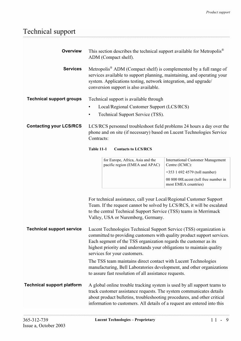
Product support
1 1 - 9Lucent Technologies – Proprietary365-312-739Issue a, October 2003
..............................................................................................................................................................................................................................................................
...............................................................................................................................................................................................................................................................Technical support
Overview This section describes the technical support available for Metropolis® ADM (Compact shelf).
Services Metropolis® ADM (Compact shelf) is complemented by a full range of services available to support planning, maintaining, and operating your system. Applications testing, network integration, and upgrade/conversion support is also available.
Technical support groups Technical support is available through
• Local/Regional Customer Support (LCS/RCS)
• Technical Support Service (TSS).
Contacting your LCS/RCS LCS/RCS personnel troubleshoot field problems 24 hours a day over the phone and on site (if necessary) based on Lucent Technologies Service Contracts:
Table 11-1 Contacts to LCS/RCS
For technical assistance, call your Local/Regional Customer Support Team. If the request cannot be solved by LCS/RCS, it will be escalated to the central Technical Support Service (TSS) teams in Merrimack Valley, USA or Nuremberg, Germany.
Technical support service Lucent Technologies Technical Support Service (TSS) organization is committed to providing customers with quality product support services. Each segment of the TSS organization regards the customer as its highest priority and understands your obligations to maintain quality services for your customers.
The TSS team maintains direct contact with Lucent Technologies manufacturing, Bell Laboratories development, and other organizations to assure fast resolution of all assistance requests.
Technical support platform A global online trouble tracking system is used by all support teams to track customer assistance requests. The system communicates details about product bulletins, troubleshooting procedures, and other critical information to customers. All details of a request are entered into this
for Europe, Africa, Asia and the pacific region (EMEA and APAC)
International Customer Management Centre (ICMC):
+353 1 692 4579 (toll number)
00 800 00Lucent (toll free number in most EMEA countries)
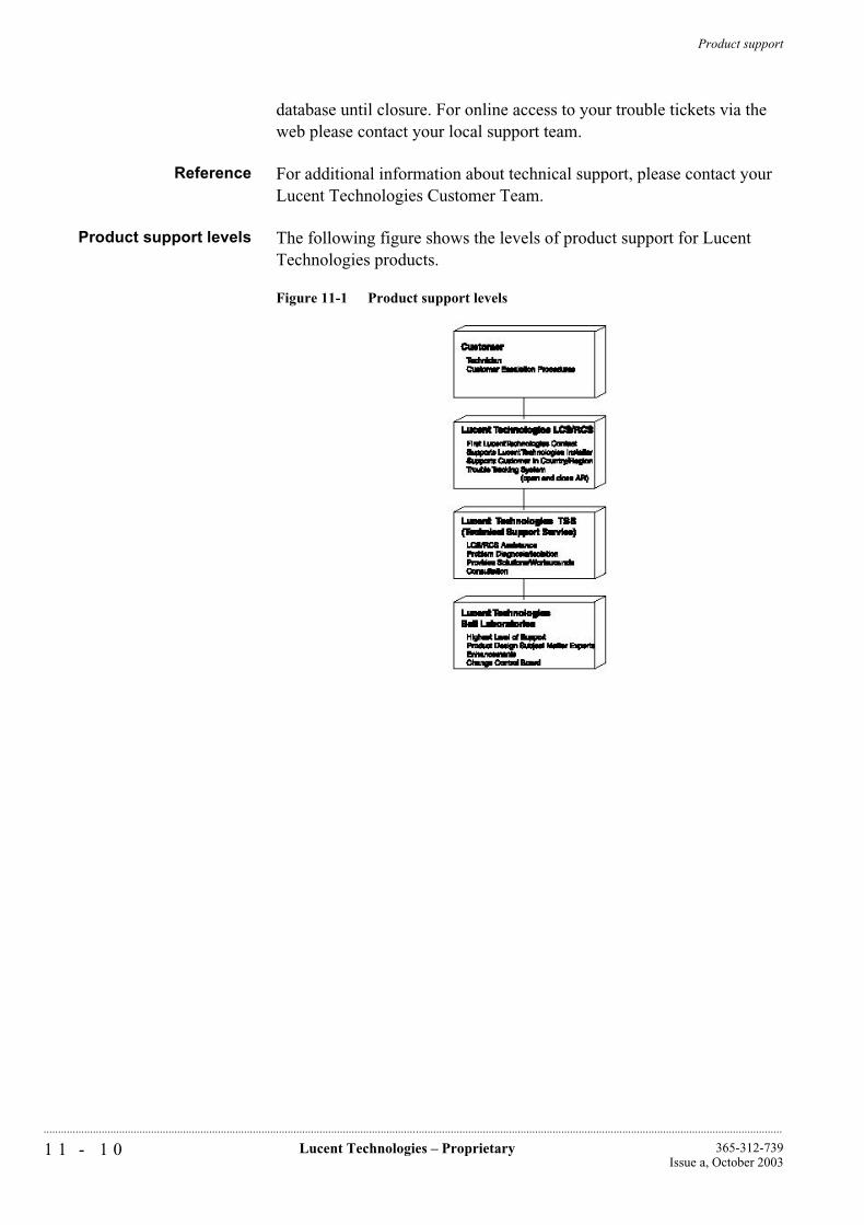
Product support
1 1 - 1 0 Lucent Technologies – Proprietary 365-312-739Issue a, October 2003
..............................................................................................................................................................................................................................................................
database until closure. For online access to your trouble tickets via the web please contact your local support team.
Reference For additional information about technical support, please contact your Lucent Technologies Customer Team.
Product support levels The following figure shows the levels of product support for Lucent Technologies products.
Figure 11-1 Product support levels
Product support
1 1 - 1 1Lucent Technologies – Proprietary365-312-739Issue a, October 2003
..............................................................................................................................................................................................................................................................
...............................................................................................................................................................................................................................................................Documentation support
Overview Lucent Technologies provides comprehensive product documentation tailored to the needs of the different audiences. An overview of the documentation set can be found at “Related documentation” (xviii).
Customer comment As customer satisfaction is extremely important to Lucent Technologies, every attempt is made to encourage feedback from customers about our information products. Thank you for your feedback.
To comment on this information product online, go to http://www.lucent-info.com/comments or email your comments to [email protected].
You can also send or fax comments about this document to:
Lucent Technologies Network Systems GmbHThurn-und-Taxis-Str. 1090411 Nürnberg, GermanyFax: +49 911 526 3545.

Product support
1 1 - 1 2 Lucent Technologies – Proprietary 365-312-739Issue a, October 2003
..............................................................................................................................................................................................................................................................
...............................................................................................................................................................................................................................................................Training support
Overview To complement your product needs, the Lucent Learning organization offers a formal training package, with the single training courses scheduled regularly at Lucent Technologies’ corporate training centers or to be arranged as on-site trainings at your facility.
Registering for a course orarranging an on-site
training
To enroll in a training course at one of the Lucent Technologies corporate training centers or to arrange an on-site training at your facility (suitcasing), please contact:
Table 11-2 Course registering
To review the available courses or to enroll in a training course at one of Lucent Technologies’ corporate training centers you can also visit:
https://www.lucent-product-training.com.
in Germany Birgit Pfaelzner
voice: +49 911 526 3831
fax: +49 911 526 6142
e-mail: [email protected]
in Singapore Jenny Ong
voice: +65 6240 8394
fax: +65 6240 8017
e-mail: [email protected]
in the USA voice: +1-888-582-3688 - prompt 2
(+1-888-LUCENT8 - prompt 2)
Product support
1 1 - 1 3Lucent Technologies – Proprietary365-312-739Issue a, October 2003
..............................................................................................................................................................................................................................................................
...............................................................................................................................................................................................................................................................Training courses
Overview This section describes the Metropolis® ADM (Compact shelf) training
courses:
As a prerequisite for all courses the students should be familiar with
basic SDH principles.
SDH introduction course(TR5951)
This course is designed for technical personnel who need to know the equipmentís functional and physical features and the applications and possibilities of the Metropolis® ADM (Compact shelf) system and its management system. The courseís high-level approach makes it suitable for personnel from service, purchase and planning departments as well.
Duration: 2 days
Metropolis® ADM (Compactshelf) Application and
Planning course (TR6000b)
This course provides an introduction to the features, network applications, unit descriptions, and configurations of the Metropolis® ADM (Compact shelf).
The intended audience for this course are technical personnel who need to know the functional and physical features of the equipment and the application possibilities of the system. The course may also be of interest to personnel from sales, logistics, service, purchasing, or planning environments.
Duration: 1 day
Metropolis® ADM (Compactshelf) Operation and
Maintenance (TR6001)
This course provides an introduction to the features, network applications, unit descriptions and configurations of the Metropolis® ADM (Compact shelf). The course covers installation, testing, provisioning of equipment, monitoring of events, and maintenance using the ITM-CIT.
Duration: 5 days
WaveStar® ITM-SCOperations Course
(TR5965A)
This course provides an introduction to the features, network applications, and configurations of the WaveStar® ITM-SC. In addition, this course covers provisioning, monitoring of events, and maintenance activities by means of hands-on exercises using the WaveStar® ITM-SC, for the following network element equipment:
• SLM-16
• ISM
• ADM 155 C
• WaveStar® OLS 80G
• WaveStar® TM 1
Product support
1 1 - 1 4 Lucent Technologies – Proprietary 365-312-739Issue a, October 2003
..............................................................................................................................................................................................................................................................
• WaveStar® AM 1 Plus
• WaveStar® ADM 4/1
• WaveStar® ADM 16/1
• WaveStar® ADM 16/1 Compact
• WaveStar® DACS 4/4/1
• Metropolis® ADM (Compact shelf).
The course can be modified to cover only those network elements that are deployed in the customer’s network.
The objectives are to enable students to:
• Identify features, applications, descriptions, and configurations
• Provision site-specific configurations of SDH network elements
• Interpret system events and apply corrective actions
• Provide maintenance support.
Duration: 5 days
G L O S S A R YG L - 1
365-312-739Issue a, October 2003
............................................................................................................................................................................................................................................................
............................................................................................................................................................................................................................................................
Glossary
# 5ESS
Number 5 Electronic Switching System
5TAD
Five Tributary Add-Drop subrack
9TAD
Nine Tributary Add-Drop subrack
12 digit Numerical Code (12NC)
Used to as the unique identifier of an item or product. The first ten digits identify an item. The eleventh digit specifies the particular variant of the item. The twelfth digit indicates the revision issue. Items for which the first eleven digitsare the same are functionally equal and may be exchanged.
A AAU
Alarm Adapter Unit. Radio Relay circuit pack that is used for the collection of external alarms and remote control of external equipment.
AC
Alternating Current
ACU
Alarm Collection Unit. Radio Relay circuit pack that collects of equipment alarms, analogue measurements from internal monitoring points and calculation data.
ADM
Add-Drop Multiplexer
Administrative Unit (AU)
Carrier for TUs
G L O S S A R YG L - 2
365-312-739Issue a, October 2003
.........................................................................................................................................................................................................................................................
Administrative-Unit Pointer (AU PTR)
Indicates the phase alignment of the VC-n with respect to the STM-N frame. The pointer position is fixed with respect to the STM-N frame.
Administrator
See WaveStar® ITM-SC System Administrator.
Agent
Performs operations on managed objects and issues events on behalf of these managed objects. All SDH managed objects will support at least one agent. Control of distant agents is possible via local “Managers”.
Alarm
The notification (audible or visual) of a significant event. See also Event.
Alarm Indication Signal (AIS)
Code transmitted downstream in a digital Network that shows that an upstream failure has been detected and also alarmed if the upstream alarm has not been suppressed. Also called to as All OneS.
ALS
Automatic Laser Shutdown
Alarm Severity
An attribute that defines the priority of the alarm message. The way in which alarms are processed depends on the severity.
Aligning
Using a pointer to indicate the head of a virtual container, e.g. to create an Administrative Unit (AU) or a Tributary Unit (TU).
Alternate Mark Inversion (AMI)
A line code that employs a ternary signal to convert binary digits. In this line code successive binary ones are represented by signal elements that are normally of alternately positive and negative polarity but are equal in amplitude, binary zeros are represented by signal elements that have zero amplitude.
American Standard Code for Information Interchange (ASCII)
A standard 8-bit code that is used to exchange information among data processing systems and associated equipment.
Anomaly
A difference between the actual and the desired operation of a function.
ANSI
American National Standards Institute

G L O S S A R YG L - 3
365-312-739Issue a, October 2003
...........................................................................................................................................................................................................................................................
Assembly
Gathering together of payload data with overhead and pointer information (an indication of the direction of the signal).
APS
Automatic Protection Switching
AS
Alarm Suppression assembly
Association
A logical connection between manager and agent through which management information can be exchanged.
Asynchronous
See Non-synchronous.
ATC
Auxiliary Transmission Channel
ATM
Asynchronous Transfer Mode
ATPC
Automatic Transmit-Power Control
AU
Administrative Unit
AU4AD
Administrative Unit 4 Assembler/Disassembler
AUG
Administrative Unit Group
AUTO
Automatic
Automatic Transmit Power Control (ATPC)
Reduces the power output from the transmitter during normal propagation conditions and increases the power output to maximum during fading periods to try to maintain the nominal level of receiver input.
Autonomous Message
A message transmitted from the controlled network element to the WaveStar® ITM-SC that was not a response to a command that orginated in the WaveStar® ITM-SC.

G L O S S A R YG L - 4
365-312-739Issue a, October 2003
.........................................................................................................................................................................................................................................................
............................................................................................................................................................................................................................................................
B B3ZS
Bipolar 3-Zero Substitution
B8ZS
Bipolar 8-Zero Substitution
BBTR
Backplane Bus TRansceiver
BC
Board Controller
BCC
Board Controller Complex
BIN
BINary
BIP
Bit-Interleaved Parity
BISDN
Broadband Integrated Services Digital Network
Bit Error Ratio (BER)
The ratio of bits received in error to bits sent.
Bit Interleaved Parity (BIP)
A method of error monitoring that uses a specified number of bits (BIP-8)
BLD OUT LG
Build-Out Lightguide
Board Controller Local Area Network (BC-LAN)
The internal local area network that provides communications between the Line Controller circuit pack and board controllers on the circuit packs that are associated with a high-speed line.
Branching
Interconnection of independent line systems.
Broadband Communication
Voice, data, and/or video communication at greater than 2 Mbit/s rates.
Broadband Service Transport
STM-1 concatenation transport over the SLM for ATM applications.
G L O S S A R YG L - 5
365-312-739Issue a, October 2003
...........................................................................................................................................................................................................................................................
...............................................................................................................................................................................................................................................................
BUSTR
BUS Transmitter and Receiver
C CAS
Channel Associated Signaling
CAT
CATastrophic
CC
Cross-Connection, Cross-Connect
CCIR
See ITU-R.
CCITT
See ITU-T.
CCS
Common Channel Signaling
CEPT
Conférence Européenne des Administrations des Postes et des Télécommunications
Channel
A sub-unit of transmission capacity within a defined higher level of transmission capacity, e.g. a CEPT-4 (140 Mbit/s) within a 565 Mbit fiber system.
Circuit
A combination of two transmission channels that permits bidirectional transmission of signals between two points to support a single communication.
CIR
Committed Information Rate
CIT
Craft Interface Terminal
Clear Channel (Cl. Ch.)
A provisionable mode for the 34 and 140 Mbit/s tributary outputs that causes parity violations not to be monitored or corrected before the 34 and 140 Mbit/s outputs are encoded.
Client
Computer in a computer network that generally offers a user interface to a server. See also Server.
G L O S S A R YG L - 6
365-312-739Issue a, October 2003
.........................................................................................................................................................................................................................................................
CMI
Coded Mark Inversion
CO
Central Office
Concatenation
A procedure whereby a multiplicity of Virtual Containers are associated with each other with the result that their combined capacity can be used as a single container across which bit-sequence integrity is maintained.
Configuration Management (CM)
Subsystem of the WaveStar® ITM-SC that, among other things, configures the network and processes messages from the network.
CONN PCB
Connector Printed Circuit Board
Container (C)
Carries plesiochronous signal, the “payload”.
Co-resident
A hardware configuration where the WaveStar® ITM-SC and ITM-NM applications can be independently active at the same time on the same hardware and software platform without interfering with each other's functioning.
Common Object Request Broker Architecture (CORBA)
CORBA allows applications to communicate with one another no matter where they are located or who has designed them.
CP
Circuit Pack
Craft Interface Terminal (CIT)
Local manager for SDH network elements.
CRC
Cyclic Redundancy Check
Cross-Connect Map
Connection map for an SDH network element; contains information about how signals are connected between high speed time slots and low speed tributaries. See also Squelch Map.
Cross-Polarization Interference Cancellation
This feature permits both orthogonal polarizations of one Radio Frequency carrier to be used simultaneously, which provides greater spectral efficiency.

G L O S S A R YG L - 7
365-312-739Issue a, October 2003
...........................................................................................................................................................................................................................................................
...............................................................................................................................................................................................................................................................
CTP
Connection Termination Point
CV
Code Violation
D DACS
Digital Access & Cross-connect System
DACScan-T
See Integrated Transport Management Network Manager.
Database Administrator
A user who administers the database of the WaveStar® ITM-SC application. See also User Privilege.
Data Communication Channel (DCC)
The embedded overhead communication channel in the SDH line. The DCC is used for end-to-end communication and maintenance. It carries alarm, control, and status information between network elements in an SDH network.
Data Communication Equipment (DCE)
Provides the signal conversion and coding between the data terminating equipment and the line. The DCE may be separate equipment or a part of the data terminating equipment.
Data Terminating Equipment (DTE)
Originates data for transmission and accepts transmitted data.
DC
Direct Current
DCF
Data Communications Function
DCN
Data Communications Network
DCS
Digital Cross-connect System
DDF
Digital Distribution Frame
Dedicated Protection Ring (DP-Ring)
A protection method used in some network elements.

G L O S S A R YG L - 8
365-312-739Issue a, October 2003
.........................................................................................................................................................................................................................................................
Default Value Provisioning
The original values are preprogrammed at the factory. These values can be overridden using local or remote provisioning.
Defect
A limited interruption of the ability of an item to perform a required function. The defect may or may not lead to maintenance action this depends on the results of additional analysis.
Demultiplexing
A process applied to a multiplexed signal to recover signals combined within it and restore the distinct individual channels of these signals.
Digital Link
A transmission span such as a point-to-point 2 Mbit/s, 34 Mbit/s, 140 Mbit/s, VC12, VC3 or VC4 link between controlled network elements. The channels within a digital link are insignificant.
Digital Section
A transmission span such as an STM-N or 565 Mbit/s signal. A digital section may contain multiple digital channels.
DIL
Dual In Line
Directory-Service Network Element (DSNE)
A designated network element that is responsible for administering a database that maps network element names (node names) to addresses (node Id). There can be one DSNE per (sub)network.
Disassembly
Splitting up of a signal into its constituents as payload data and overhead (an indication of the direction of a signal).
Domain
The domain of an WaveStar® ITM-SC is the set of all SDH network elements that are controlled by that particular WaveStar® ITM-SC.
Downstream
At or towards the destination of the considered transmission stream, i.e. in the direction of transmission.
DPLL
Digital Phase-Locked Loop
DPS
Data communication Packet Switch
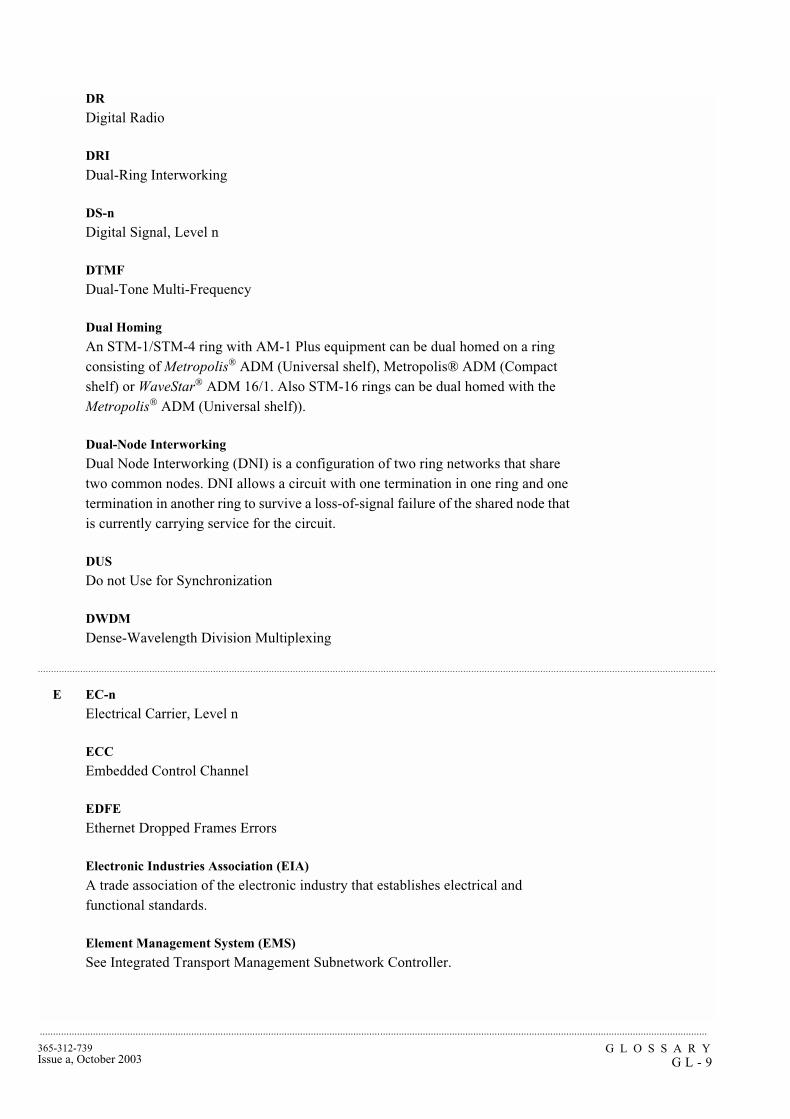
G L O S S A R YG L - 9
365-312-739Issue a, October 2003
...........................................................................................................................................................................................................................................................
...............................................................................................................................................................................................................................................................
DR
Digital Radio
DRI
Dual-Ring Interworking
DS-n
Digital Signal, Level n
DTMF
Dual-Tone Multi-Frequency
Dual Homing
An STM-1/STM-4 ring with AM-1 Plus equipment can be dual homed on a ring consisting of Metropolis® ADM (Universal shelf), Metropolis® ADM (Compact shelf) or WaveStar® ADM 16/1. Also STM-16 rings can be dual homed with the Metropolis® ADM (Universal shelf)).
Dual-Node Interworking
Dual Node Interworking (DNI) is a configuration of two ring networks that share two common nodes. DNI allows a circuit with one termination in one ring and one termination in another ring to survive a loss-of-signal failure of the shared node that is currently carrying service for the circuit.
DUS
Do not Use for Synchronization
DWDM
Dense-Wavelength Division Multiplexing
E EC-n
Electrical Carrier, Level n
ECC
Embedded Control Channel
EDFE
Ethernet Dropped Frames Errors
Electronic Industries Association (EIA)
A trade association of the electronic industry that establishes electrical and functional standards.
Element Management System (EMS)
See Integrated Transport Management Subnetwork Controller.

G L O S S A R YG L - 1 0
365-312-739Issue a, October 2003
.........................................................................................................................................................................................................................................................
EH&S
Environmental Health and Safety
EINB
Ethernet Incoming Number of Mbytes
EMC
ElectroMagnetic Compatibility
EMI
ElectroMagnetic Interference
EONB
Ethernet Outgoing Number of Mbytes
EOW
Engineering Order Wire
Equivalent Bit Error Ratio (EBER)
The calculated average bit error rate over a data stream.
Errored Second (ES)
A performance monitoring parameter.
ES
End System
ESD
ElectroStatic Discharge
ESPG
Elastic Store & Pointer Generator
ETSI
European Telecommunication Standardisation Institute
Event
A significant change. Events in controlled network elements include signal failures, equipment failures, signals exceeding thresholds, and protection switch activity. When an event occurs in a controlled network element, the controlled network element will generate an alarm or status message and send it to the WaveStar® ITM-SC.
Event Management (EM)
Subsystem of the WaveStar® ITM-SC that processes and logs event reports of the network.

G L O S S A R YG L - 1 1
365-312-739Issue a, October 2003
...........................................................................................................................................................................................................................................................
...............................................................................................................................................................................................................................................................
...............................................................................................................................................................................................................................................................
Externally Timed
An operating condition of a clock in which it is locked to an external reference and uses time constants that are altered to quickly bring the local oscillator's frequency into approximate agreement with the synchronization reference frequency.
Extra Traffic
Unprotected traffic that is carried over the protection channels when that capacity is not used for the protection of service traffic.
F Far End Block Error (FEBE)
An indication returned to the transmitting node that an errored block has been detected at the receiving node. A block is a specified grouping of bits.
Far End Receive Failure (FERF)
An indication returned to a transmitting network element that the receiving network element has detected an incoming section failure.
FAS
Frame Alignment Signal
FAW
Frame Alignment Word
FC
Full contact Connector
FCC
Federal Communications Commission
FDDI
Fiber Distributed Data Interface
FEP
Front End Processor
Free Running
An operating condition of a network element in which its local oscillator is not locked to any synchronization reference and uses no storage techniques to sustain its accuracy.
G GARP
Generic Attribute Registration Protocol
Geographic Location
Location of the ITM-SC server. the geographic locationis entered as part of the installation procedure of an ITM-SC.

G L O S S A R YG L - 1 2
365-312-739Issue a, October 2003
.........................................................................................................................................................................................................................................................
............................................................................................................................................................................................................................................................
Gateway Network Element (GNE)
Passes information between other network elements and management systems via a Data Communications Network.
Gbit/s
Gigabits per second
Geographic Redundancy (GR)
Allows protection of management for a network element by assigning the network element to two ITM-SCs. The first primary ITM-SC usually manages the Network Element and is now in the protected domain. If the primary ITM-SC or the link between the network element and the primary ITM-SC fails, the secondary ITM-SC will automatically take over management of the network element and is now in the protecting domain. The two ITM-SCs are connected by a peer to peer link, which they use to pass Geographic Redundancy management information to each other. This link must be established before any network element can be protected by Geographic Redundancy.
GFP
Generic Framing Procedure
Global Wait to Restore Time
The time to wait before switching back to the timing reference occurs after a timing link failure has cleared. This time applies for all timing sources in a system hence the name global. This can be between 0 and 60 minutes, in increments of one minute.
GNE
Gateway network element - A network element that passes information between other network elements and operations systems via a data communications network.
GUI
Graphical User Interface
GVRP
GARP VLAN Registration Protocol (refer to “GARP” (GL-11))
H HE
Host Exchange
High Density Bipolar 3 code (HDB3)
Line code for e.g. 2 Mbit/s transmission systems.
High level Data Link Control (HDLC)
Protocol in the data-link layer of the OSI reference model.

G L O S S A R YG L - 1 3
365-312-739Issue a, October 2003
...........................................................................................................................................................................................................................................................
...............................................................................................................................................................................................................................................................
Higher order Path Adaptation (HPA)
Function that adapts a lower order Virtual Container to a higher order Virtual Container by processing the Tributary Unit pointer which indicates the phase of the lower order Virtual Container Path Overhead relative to the higher order Virtual-Container Path Overhead, and assembling/disassembling the complete higher order Virtual Container.
Higher order Path Connection (HPC)
Function that provides for flexible assignment of higher order Virtual Containers within an STM-N signal.
Higher order Path Termination (HPT)
Function that terminates a higher order path by generating and adding the appropriate Virtual-Container Path Overhead to the relevant container at the path source and removing the Virtual-Container Path Overhead and reading it at the path sink.
HMI
Human Machine Interface
HO
High Order
Holdover
An operating condition of a clock in which its local oscillator is not locked to an external reference but uses storage techniques to maintain its accuracy with respect to the last known frequency comparison with a synchronized reference.
Host Name
Name of the server on which the ITM-SC is running.
HS
High Speed
I ICB
Interconnection Box
ICP
InterConnection Panel
IEC
International Electrotechnical Committee
IEEE
Institute of Electrical and Electronic Engineers

G L O S S A R YG L - 1 4
365-312-739Issue a, October 2003
.........................................................................................................................................................................................................................................................
IF
Intermediate Frequency
IFT
InterFace Terminal
Intelligent Synchronous Multiplexer (ISM)
A network multiplexer that is designed to flexibly multiplex plesiochronous and STM-1 tributary port signals into STM-1 or STM-4 line port signals.
Integrated Transport Management Craft Interface Terminal (ITM-CIT)
Local manager for SDH network elements in a subnetwork. Also called the to as Craft Interface Terminal.
Intermediate System (IS)
A system that routes/relays management information. An SDH network element may be a combined Intermediate and end system.
I/O
Input/Output
IPS
Inter Processor Status
IS
In-Service
ISDN
Integrated Services Digital Network
IS-IS Routing
The network elements in a management network, route packets (data) between each other using an IS-IS level protocol. The size of a network that is running IS-IS Level 1 is limited, and therefore certain mechanisms are employed to facilitate the management of larger networks. For STATIC ROUTING, it is possible to disable the protocol over the LAN connections and thereby effectively cause the management network to be partitioned into separate IS-IS Level 1 areas. In order for the ITM-SC to communicate with a specific network element in one of these areas, the ITM-SC must identify the Gateway network elementthrough which this specific network element is connected to the LAN. All packets to this specific network element are routed directly to the Gateway network element by the ITM-SC, before being re-routed (if necessary) within the Level 1 area. For DYNAMIC ROUTING an IS-IS Level 2 routing protocol is used that allows a number of Level 1 areas to interwork. The network elements that connect an IS-IS area to another area are set to run the IS-IS Level 2 protocol within the network element and on the connection to other network elements. Packets can now be routed between IS-IS areas and the ITM-SC does not have to identify the Gateway network elements.
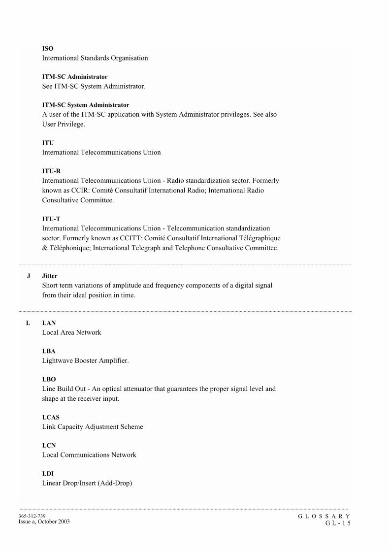
G L O S S A R YG L - 1 5
365-312-739Issue a, October 2003
...........................................................................................................................................................................................................................................................
...............................................................................................................................................................................................................................................................
...............................................................................................................................................................................................................................................................
ISO
International Standards Organisation
ITM-SC Administrator
See ITM-SC System Administrator.
ITM-SC System Administrator
A user of the ITM-SC application with System Administrator privileges. See also User Privilege.
ITU
International Telecommunications Union
ITU-R
International Telecommunications Union - Radio standardization sector. Formerly known as CCIR: Comité Consultatif International Radio; International Radio Consultative Committee.
ITU-T
International Telecommunications Union - Telecommunication standardization sector. Formerly known as CCITT: Comité Consultatif International Télégraphique & Téléphonique; International Telegraph and Telephone Consultative Committee.
J Jitter
Short term variations of amplitude and frequency components of a digital signal from their ideal position in time.
L LAN
Local Area Network
LBA
Lightwave Booster Amplifier.
LBO
Line Build Out - An optical attenuator that guarantees the proper signal level and shape at the receiver input.
LCAS
Link Capacity Adjustment Scheme
LCN
Local Communications Network
LDI
Linear Drop/Insert (Add-Drop)

G L O S S A R YG L - 1 6
365-312-739Issue a, October 2003
.........................................................................................................................................................................................................................................................
LED
Light Emitting Diode
LEN
Local Exchange Node
LF
Low Frequency
LH
Long Haul
License key
An encrypted code that is required to enable the use of specific modules in the ITM-SC. Valid license keys can be obtained from your provider.
Line
Transmission line; refers to a transmission medium, together with the associated high speed equipment, that are required transport information between two consecutive network elements, one of which originates the line signal and the other terminates the line signal.
Line Build Out (LBO)
An optical attenuator that guarantees the proper signal level and shape at the receiver input.
Line Overhead Controller (LOC)
SLM circuit pack that accesses the overhead bytes from the high speed line.
LNC
LiNe Controller (SLM)
LO
Low Order
LOF
Loss Of Frame
LOM
Loss Of Multiframe
Loop Timing
A timing mode in which the terminal derives its transmit timing from the received line signal.
LOP
Loss Of Pointer

G L O S S A R YG L - 1 7
365-312-739Issue a, October 2003
...........................................................................................................................................................................................................................................................
...............................................................................................................................................................................................................................................................
LOS
Loss Of Signal
Lower order Path Adaptation (LPA)
Function that adapts a PDH signal to a synchronous network by mapping the signal into or de-mapping the signal out of a synchronous container.
Lower order Path Connection (LPC)
Function that provides for flexible assignment of lower order VCs in a higher order VC.
Lower order Path Termination (LPT)
Function that terminates a lower order path by generating and adding the appropriate VC POH to the relevant container at the path source and removing the VC POH and reading it at the path sink.
LPU
Line Port Unit
LPU155
Line Port Unit 155 Mbit/s
LRX
Line Receiver
LS
Low Speed
LTA
Line Terminal Application
LTX
Line Transmitter
LTX/EML
Line Transmitter with Electro-absorption Modulated Laser
M Manager
Is capable of issuing network management operations and receiving events
MAF
Management Application Function
Management Connection
Identifies the type of routing used (STATIC or DYNAMIC). If STATIC is selected, Management Connection allows the gateway network element to be identified. See also IS-IS Routing.
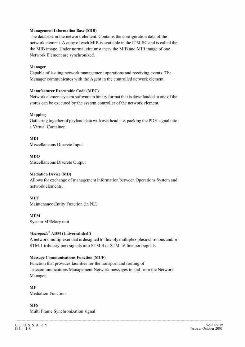
G L O S S A R YG L - 1 8
365-312-739Issue a, October 2003
.........................................................................................................................................................................................................................................................
Management Information Base (MIB)
The database in the network element. Contains the configuration data of the network element. A copy of each MIB is available in the ITM-SC and is called the the MIB image. Under normal circumstances the MIB and MIB image of one Network Element are synchronized.
Manager
Capable of issuing network management operations and receiving events. The Manager communicates with the Agent in the controlled network element.
Manufacturer Executable Code (MEC)
Network element system software in binary format that is downloaded to one of the stores can be executed by the system controller of the network element.
Mapping
Gathering together of payload data with overhead, i.e. packing the PDH signal into a Virtual Container.
MDI
Miscellaneous Discrete Input
MDO
Miscellaneous Discrete Output
Mediation Device (MD)
Allows for exchange of management information between Operations System and network elements.
MEF
Maintenance Entity Function (in NE)
MEM
System MEMory unit
Metropolis® ADM (Universal shelf)
A network multiplexer that is designed to flexibly multiplex plesiochronous and/or STM-1 tributary port signals into STM-4 or STM-16 line port signals.
Message Communications Function (MCF)
Function that provides facilities for the transport and routing of Telecommunications Management Network messages to and from the Network Manager.
MF
Mediation Function
MFS
Multi Frame Synchronization signal

G L O S S A R YG L - 1 9
365-312-739Issue a, October 2003
...........................................................................................................................................................................................................................................................
MIB
The Management Information Base is the database in the node. The MIB contains the configuration data of the node. A copy of each MIB is available in the EMS and is called the MIB image. Under normal circumstances, the MIB and MIB image of one node are synchronized.
MIB image
See Management Information Base.
Midspan Meet
The capability to interface between two lightwave network elements of different vendors. This applies to high speed optical interfaces.
MLAN
MultiLAN
MMI
Man-Machine Interface Also called Human Machine Interface (HMI)
MO
Managed Object
Motif
X-Windows System supplied by Open Software Foundation.
MS
Multiplexer Section
MSOH
Multiplex Section Overhead. Part of the SOH (Section Overhead). Is accessible only at line terminals and multiplexers.
MSP
Multiplex Section Protection. Provides capability of switching a signal from a working to a protection section.
MTBF
Mean Time Between Failures
MTBMA
Mean Time Between Maintenance Activities
MTIE
Maximum Time Interval Error
MTPI
Multiplexer Timing Physical Interface

G L O S S A R YG L - 2 0
365-312-739Issue a, October 2003
.........................................................................................................................................................................................................................................................
............................................................................................................................................................................................................................................................
MTTR
Mean Time To Repair
Multiplexer Section OverHead (MSOH)
Part of the Section Overhead. Is accessible only at line terminals and multiplexers.
Multiplexer Section Protection (MSP)
Provides capability of switching a signal from a working to a protection section.
Multiplexer Section Shared Protection Ring (MS-SPRING)
A protection method used in multiplex line systems.
Multiplexer Section Termination (MST)
Function that generates the Multiplexer Section Overhead in the transmit direction and terminates the Multiplexer Section Overhead in the receive direction.
Multiplexer Timing Source (MTS)
Function that provides the timing reference to the relevant component parts of the multiplex equipment and represents the SDH network element clock.
Multiplexing
A procedure by which multiple lower order path layer signals are adapted into a higher order path, or by which the multiple higher order path layer signals are adapted into a multiplex section.
N NE
Network element. The NE is comprised of telecommunication equipment (or groups/parts of telecommunication equipment) and support equipment that performs network element functions. A Network Element has one or more standard Q-type interfaces.
NEF
Network element function
NEM
Network element manager
Node
A node or network element is defined as all equipment that is controlled by one system controller.
Non-revertive switching
In non-revertive switching, there is an active and standby high-speed line, circuit pack, etc. When a protection switch occurs, the standby line, circuit pack, etc., is selected causing the old standby line, circuit pack, etc., to be used for the new active line, circuit pack, etc. The original active line, circuit pack, etc., becomes the standby line, circuit pack, etc. This status remains in effect when the fault clears.
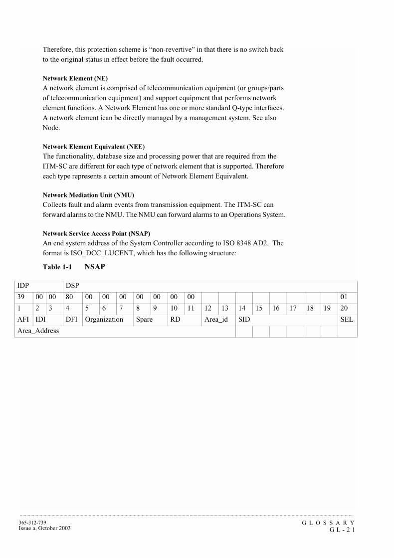
G L O S S A R YG L - 2 1
365-312-739Issue a, October 2003
...........................................................................................................................................................................................................................................................
Therefore, this protection scheme is “non-revertive” in that there is no switch back to the original status in effect before the fault occurred.
Network Element (NE)
A network element is comprised of telecommunication equipment (or groups/parts of telecommunication equipment) and support equipment that performs network element functions. A Network Element has one or more standard Q-type interfaces. A network element ican be directly managed by a management system. See also Node.
Network Element Equivalent (NEE)
The functionality, database size and processing power that are required from the ITM-SC are different for each type of network element that is supported. Therefore each type represents a certain amount of Network Element Equivalent.
Network Mediation Unit (NMU)
Collects fault and alarm events from transmission equipment. The ITM-SC can forward alarms to the NMU. The NMU can forward alarms to an Operations System.
Network Service Access Point (NSAP)
An end system address of the System Controller according to ISO 8348 AD2. The format is ISO_DCC_LUCENT, which has the following structure:
Table 1-1 NSAP
IDP DSP
39 00 00 80 00 00 00 00 00 00 00 01
1 2 3 4 5 6 7 8 9 10 11 12 13 14 15 16 17 18 19 20
AFI IDI DFI Organization Spare RD Area_id SID SEL
Area_Address
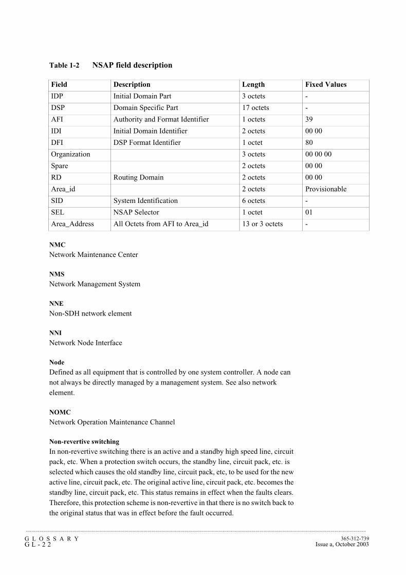
G L O S S A R YG L - 2 2
365-312-739Issue a, October 2003
.........................................................................................................................................................................................................................................................
Table 1-2 NSAP field description
NMC
Network Maintenance Center
NMS
Network Management System
NNE
Non-SDH network element
NNI
Network Node Interface
Node
Defined as all equipment that is controlled by one system controller. A node can not always be directly managed by a management system. See also network element.
NOMC
Network Operation Maintenance Channel
Non-revertive switching
In non-revertive switching there is an active and a standby high speed line, circuit pack, etc. When a protection switch occurs, the standby line, circuit pack, etc. is selected which causes the old standby line, circuit pack, etc, to be used for the new active line, circuit pack, etc. The original active line, circuit pack, etc. becomes the standby line, circuit pack, etc. This status remains in effect when the faults clears. Therefore, this protection scheme is non-revertive in that there is no switch back to the original status that was in effect before the fault occurred.
Field Description Length Fixed Values
IDP Initial Domain Part 3 octets -
DSP Domain Specific Part 17 octets -
AFI Authority and Format Identifier 1 octets 39
IDI Initial Domain Identifier 2 octets 00 00
DFI DSP Format Identifier 1 octet 80
Organization 3 octets 00 00 00
Spare 2 octets 00 00
RD Routing Domain 2 octets 00 00
Area_id 2 octets Provisionable
SID System Identification 6 octets -
SEL NSAP Selector 1 octet 01
Area_Address All Octets from AFI to Area_id 13 or 3 octets -
G L O S S A R YG L - 2 3
365-312-739Issue a, October 2003
...........................................................................................................................................................................................................................................................
...............................................................................................................................................................................................................................................................
Non-synchronous
The essential characteristic of timescales or signals such that their significant instants do not necessarily occur at the same average rate.
Not Protected Domain
The Not Protected Domain for the ITM-SC contains all the network elements that are managed by that ITM-SC and are not currently protected by another ITM-SC. If the ITM-SC fails, the network elements in this domain are not managed by any ITM-SC. See also Geographic Redundancy.
NPI
Null Pointer Indication
NRZ
Non-Return to Zero
NSA
Non-Service Affecting
NUT
Non pre-emptible Unprotected Traffic
NVM
Non-Volatile Memory
O OA
Optical Amplifier
OAA case tools
A software package/tool to aid the process of requirements, analysis, design and implementation of object orientated systems.
OAM&P
Operations, Administration, Maintenance and Provisioning
OC-n
Optical Carrier, Level n
ODF
Optical Distribution Frame
ODU
Optical Demultiplexer Unit
OFS
Out of Frame Second
G L O S S A R YG L - 2 4
365-312-739Issue a, October 2003
.........................................................................................................................................................................................................................................................
............................................................................................................................................................................................................................................................
OI
Optical Interface
OMU
Optical Multiplexer Unit
Operations System (OS)
The Operations System is the system that provides operations, administration and maintenance functions.
Operator
A user of the ITM-SC application with Operator privileges. See also User Privilege.
Optical Line System (OLS)
A high-capacity lightwave system that is designed to multiplex eight optical signals with different wavelengths into one combined signal through an optical fiber. There is a difference of 1.5 micrometer in wavelength between two multiplexed signals.
OOF
Out Of Frame
OOS
Out Of Service
OSB
Optical Splice Box
OS
Operations System - A central computer-based system that is used to provide operations, administration and maintenance functions.
OSI
Open Systems Interconnection
OW
(Engineering) Order Wire
P PABX
Private Automatic Branch eXchange
Paddle Board - Peripheral Control and Timing link (PB-PCT)
A small circuit board used in a 5ESS exchange for protection switching and optical to electrical conversion of the PCT-link.

G L O S S A R YG L - 2 5
365-312-739Issue a, October 2003
...........................................................................................................................................................................................................................................................
Path
A logical connection between one termination point at which a standard format for a signal at the given rate is assembled and from which the signal is transmitted, and another termination point at which the received standard frame format for the signal is disassembled.
Path Overhead (POH)
The Virtual-Container Path Overhead provides integrity of communication between the point of assembly of a Virtual Container and its point of disassembly.
Path AIS
Path Alarm Indication Signal - A path-level code that is sent downstream in a digital network as an indication that an upstream failure has been detected and alarmed.
Path Terminating Equipment
Network elements in which the path overhead is terminated.
PC
Personal Computer
PCB
Printed Circuit Board
PCM
Pulse Code Modulation
PCT-link
Peripheral Control and Timing-link
PDH
Plesiochronous Digital Hierarchy
Peer ITM-SC
ITM-SC at the other end of the peer-to-peer link.
Peer to Peer link
Connection between two ITM-SCs with Geographic Redundancy. The link is used to co-ordinate the management of a network element. See also Geographic Redundancy.
Performance Monitoring (PM)
Measures the quality of service and identifies degrading or marginally operating systems (before an alarm is generated).
Peripheral Control and Timing Facility Interface (PCTFI)
A proprietary physical link interface that supports the transport of 21 * 2 Mbit/s signals.

G L O S S A R YG L - 2 6
365-312-739Issue a, October 2003
.........................................................................................................................................................................................................................................................
PI
Physical Interface, Plesiochronous Interface
PIR
Peak Information Rate
PJE
Pointer Justification Event
Platform
Family of equipment and software configurations that are designed to support a particular Application.
Plesiochronous Network
A network that contains multiple subnetworks, each of which is internally synchronous and operates at the same nominal frequency, but the timing of any of the subnetworks may be slightly different at any particular instant.
PLL
Phase Lock Loop
PM
Performance Monitoring - Measures the quality of service and identifies degrading or marginally operating systems (before an alarm is generated).
PMA
Performance Monitoring Application
Pointer
An indicator whose value defines the frame offset of a virtual container with respect to the frame reference of the transport entity on which the Virtual Container is supported.
POTS
Plain Old Telephone Service
PP
Pointer Processing
PPC
Pointer Processor and Cross-connect
Primary ITM-SC
ITM-SC that is usually managing a network element. If the primary ITM-SC fails, management of the network element is passed over to the secondary ITM-SC. A network element should be provisioned normally on the primary ITM-SC and then be configured for use on the secondary ITM-SC. See also Geographic Redundancy.
G L O S S A R YG L - 2 7
365-312-739Issue a, October 2003
...........................................................................................................................................................................................................................................................
...............................................................................................................................................................................................................................................................
Primary Reference Clock (PRC)
The main timing clock reference in SDH equipment.
Protected Domain
The protected domain for an ITM-SC contains all the network elements for which this manager is the primary ITM-SC and which are protected by another secondary ITM-SC. See also Geographic Redundancy.
Protecting Domain
The protecting domain for an ITM-SC contains all the network elements for which this manager is the secondary ITM-SC. See also Geographic Redundancy.
Protection
Extra capacity (channels, circuit packs) in transmission equipment that is not intended to be used for service, but rather to serve as backup against equipment failures.
Provisioning
Assigning a value to a system parameter.
PSA
Partially Service Affecting
PSDN
Public Switched Data Network
PSF
Power Supply Filter
PSF-SIP
Power Supply Filter; originally designed for an Italian customer.
PSN
Packet-Switched Network
PSTN
Public Switched Telephone Network
PT
Protected Terminal Power-supply filter and Timing circuit pack
PVID
Port VLAN ID
Q QAF
Q-Adapter Function (in NE)
G L O S S A R YG L - 2 8
365-312-739Issue a, October 2003
.........................................................................................................................................................................................................................................................
............................................................................................................................................................................................................................................................
Q-LAN
Thin Ethernet LAN (10BaseT) that connects the manager to gateway network elements so that management information can be exchanged between network elements and management systems.
QOS
Quality Of Service
Quality Level (QL)
The quality of the timing signal(s) that are provided to clock a network element. The level is provided by the Synchronization Status Marker which can accompany the timing signal. If the System and Output Timing Quality Level mode is “Enabled”, and if the signal selected for the Station-Clock Output has a quality level below the Acceptance Quality Level, the network element “squelches” the Station-Clock Output Signal, which means that no signal is forwarded at all. Possible levels are: - PRC (Primary Reference Clock) - SSU_T (Synchronization Supply Unit - Transit) - SSU_L (Synchronization Supply Unit - Local) - SEC (SDH Equipment Clock) - DUS (Do not Use for Synchronization).
R RA
Regenerator Application
Radio Protection Switching system (RPS)
The main function of the RPS is to handle the automatic and manual switching from a main channel to a common protection channel in an N+1 system.
Radio Relay (RR)
A point-to-point Digital Radio system to transport STM-1 signals via microwaves.
RCU
Rigid Connect Unit
RCVR Data Distribution Unit (RCVR)
Radio Relay circuit pack that distributes of the protection channel and the low-priority traffic in the receiver side.
RDDU
RCVR Data Distribution Unit
RDI
Remote Defect Indicator. Previously known as Far End Receive Failure (FERF).
RDI
Ring Drop/Insert (Add-Drop)
RDSV
Running Digital Sum Violations

G L O S S A R YG L - 2 9
365-312-739Issue a, October 2003
...........................................................................................................................................................................................................................................................
Receive-direction
The direction towards the cross-connect.
REGEN
Regenerator
Regenerator Loop
Loop in a network element between the Station Clock Output(s) and one or both Station Clock Inputs, which can be used to dejitterize the selected timing reference in network applications.
Regenerator Overhead Controller (ROC)
SLM circuit pack that provides user access to the SDH overhead channels at repeater sites.
Regenerator Section Termination (RST)
Function that generates the Regenerator Section Overhead (RSOH) in the transmit direction and terminates the RSOH in the receive direction.
REI
Remote Error Indication. Previously known as Far End Block Error (FEBE).
Relay Unit (RU)
Radio Relay circuit pack whose main function is to perform protection switching when the Alignment Switch in the demodulator unit is unable to perform protection switching.
Restore Timer
Counts down the time (in minutes) during which the switch waits to let the worker line recover before switching back to it. This option can be set to prevent the protection switch continually switching if a line has a continual transient fault. This field is greyed out if the mode is non-revertive.
Revertive Switching
In revertive switching, there is a working and protection high speed line, circuit pack, etc. When a protection switch occurs, the protection line, circuit pack, etc. is selected. When the fault clears, service reverts back to the original working line.
RF
Radio Frequency
RFI
Remote-Failure Indicator
RGU
ReGenerator Unit

G L O S S A R YG L - 3 0
365-312-739Issue a, October 2003
.........................................................................................................................................................................................................................................................
............................................................................................................................................................................................................................................................
Route
A series of contiguous digital sections.
RPS
Ring Protection Switching
RSM
Remote Switching Module
RSOH
Regenerator-Section OverHead; part of the SOH.
RZ
Return to Zero
S SA
Service Affecting Synchronous Adapter
SAI
Station Alarm Interface
SC
Square coupled Connector
SD
Signal Degrade
SDH
Synchronous Digital Hierarchy. Definition of the degree of control of the various clocks in a digital network over other clocks.
SDH-TE
SDH - Terminal Equipment
Specification and Design Language (SDL)
This is a standard formal language for specifying (essentially) finite state machines.
SEC
SDH Equipment Clock
Secondary ITM-SC
Backup ITM-SC for a network element should the primary ITM-SC fail. A network element should be provisioned normally on the primary ITM-SC and then be configured for use on the secondary ITM-SC. See also Geographic Redundancy.
G L O S S A R YG L - 3 1
365-312-739Issue a, October 2003
...........................................................................................................................................................................................................................................................
Section
A transport entity in the transmission media layer that provides integrity of information transfer across a section layer network connection by means of a termination function at the section layer.
Section Adaptation (SA)
Function that processes the AU-pointer to indicate the phase of the VC-3/4 POH relative to the STM-N SOH and assembles/disassembles the complete STM-N frame.
Section Overhead (SOH)
Capacity added to either an AU-4 or to an assembly of AU-3s to create an STM-1. Always contains STM-1 framing and can contain maintenance and operational functions. SOH can be subdivided into MSOH (multiplex section overhead) and RSOH (regenerator section overhead).
SEF
Support Entity Function (in NE)
Self-healing
A network's ability to automatically recover from the failure of one or more of its components.
Server
Computer in a computer network that performs dedicated main tasks that require generally sufficient performance. See also Client.
Severely Errored Frame Seconds (SEFS)
A performance monitoring parameter.
Severely Errored Second (SES)
A second that has a binary error ratio. SES is used as a performance monitoring parameter.
Severity
See Alarm Severity
Service
The operational mode of a physical entity that indicates that the entity is providing service. This designation will change with each switch action.
SH
Short Haul
SI
Synchronous Interface
G L O S S A R YG L - 3 2
365-312-739Issue a, October 2003
.........................................................................................................................................................................................................................................................
SIB
Subrack Interface Box
SLC
Subscriber Loop Carrier
SLM
Signal Label Mismatch
Smart Communication Channel (SCC)
An HDLC messaging channel between the SDH-TE and the 5ESS host node. Similar to the DCC messaging channels that are located in the STM-N section overhead.
SML
Service Management Level
SMN
SDH Management Network
SMS
SDH Management Subnetwork
SNC/I
SubNetwork Connection (protection) / Inherent monitoring
SNC/NI
SubNetwork Connection / Non Intrusive monitoring
SNR
Signal to Noise Ratio
Soft Windows
PC emulator package for HP platforms.
SOH
Section Overhead. Capacity added to either an AU-4 or to an assembly of AU-3s to create an STM-1. Always contains STM-1 framing and can contain maintenance and operational functions. SOH can be subdivided in MSOH (Multiplex Section OverHead) and RSOH (Regenerator Section OverHead).
SONET
Synchronous Optical Network
Space Diversity (SD)
Reception of the Radio signal via mirror effects on Earth.
G L O S S A R YG L - 3 3
365-312-739Issue a, October 2003
...........................................................................................................................................................................................................................................................
SPB2M
Subrack Protection for 2 Mbit/s Board
SPI
SDH Physical Interface Synchronous-Plesiochronous Interface
Standby
The operational mode of a physical entity that indicates that the entity is not providing service, but standby. This designation changes with each switch action.
STM
Synchronous Transport Module Building block of SDH.
STP
Spanning Tree Protocol
STVRP
Spanning Tree with VPN Registration Protocol
Squelch Map
Traffic map for SLM Add-Drop Multiplexer network elements that contains information for each cross-connection in the ring and indicates the source and destination network elements for the low-speed circuit to which the cross-connection belongs. This information is used to prevent traffic misconnection in rings that have isolated network elements or segments. See also Cross-Connect Map.
SSM
Synchronization Status Marker
Standby
The operational mode of a physical entity that indicates that the entity is not providing service but is on standby. This designation will change with each switch action.
Station Clock Input (SCI)
An external clock may be connected to a Station Clock Input.
Station Clock Output (SCO)
A clock signal that can be used for other systems.
STM
Synchronous Transport Module building block of SDH
Stretched Ring (STRING)
An open ring in which each node is an Add-Drop Multiplexer. The end nodes operate with one equipped high-speed line.
G L O S S A R YG L - 3 4
365-312-739Issue a, October 2003
.........................................................................................................................................................................................................................................................
STS
Synchronous Transport Signal; used in SONET.
Subnetwork
A group of interconnected/interrelated network elements. The most common connotation is an SDH network in which the network elements have Data Communications Channels (DCC) connectivity.
Supervisor
A user of the ITM-SC application with Supervisor privileges. See also User Privilege.
Supervisory Unit (SU)
Radio Relay circuit pack that gives comprehensive supervision and control facilities to the user by collecting information from the Alarm Collection Units and Alarm Adapter Units.
SVCE
Service
Switch Receive Unit (SWR)
SLM circuit pack that provides the cross-connect in the receive direction between high speed line timeslots and low speed tributaries.
Switch Transmit Unit (SWT)
SLM circuit pack that provides the cross-connect in the transmit direction between high speed line timeslots and low speed tributaries.
Switching Module (SM)
An access module from the 5ESS switch.
Synchronization Supply Unit (SSU)
A circuit pack that recovers and reshapes the clock signal in order to filter out jitter. Local (SSU_L) and Transit (SSU_T) types are available.
Synchronous
The essential characteristic of time-scales or signals such that their corresponding significant instants occur at precisely the same average rate.
Synchronous Digital Hierarchy (SDH)
A hierarchical set of digital transport structures that is standardized for the transport of suitably adapted payloads over transmission networks.
Synchronous Equipment Management Function (SEMF)
Function that converts performance data and implementation-specific hardware alarms into object-oriented messages for transmission over the DCC and/or the Q-interface. The SEMF also converts object-oriented messages that are related to other management functions so that they can pass across the S reference points.
G L O S S A R YG L - 3 5
365-312-739Issue a, October 2003
...........................................................................................................................................................................................................................................................
Synchronous Line Multiplexer (SLM)
A line multiplexer that is designed to multiplex VC-4 and STM-1 tributary port signals into STM-16 line port signals.
Synchronous Network
The synchronization of synchronous transmission systems with synchronous payloads to a master Network clock that can be traced to a single reference clock.
Synchronous Transport Module (STM)
The information structure that is used to support (section layer) connections in SDH.
System Administrator
A user of the computer system on which the ITM-SC application can be installed. See also User Privilege.
System Controller (CTL)
ISM circuit pack that controls the configuration of an Intelligent Synchronous Multiplexer system.
System Controller (SC)
A circuit pack that controls and provisions all units. It also contains the data communication packet switch functionality that is necessary for routing of management information between network elements and their management system.
System Controller (SCT)
SLM Line Terminal and Regenerator network element circuit pack that provides the highest level of system control for the Synchronous Line Multiplexer system. The SCT circuit pack provides overall administrative control of the system. The SCT memory is included in the same one circuit pack.
System Controller (STC)
SLM Add-Drop Multiplexer network element circuit pack that provides the highest level of system control for the Synchronous Line Multiplexer system. The STC circuit pack provides overall administrative control of the system. The STC memory is provided by the MEM circuit pack.
System Controller (SYSCTL)
OLS circuit pack that provides the highest level of system control for the Optical Line System. The SYSCTL circuit pack provides overall administrative control of the system. The SYSCTL memory is provided by the SYSMEM circuit pack.
System Memory Unit (MEM)
SLM Add-Drop Multiplexer network element circuit pack that provides the highest level of system control for the Synchronous Line Multiplexer system. The MEM circuit pack provides memory support for the System Controller (STC) circuit pack.
System Memory Unit (SYSMEM)
OLS circuit pack that provides the highest level of system control for the Optical
G L O S S A R YG L - 3 6
365-312-739Issue a, October 2003
.........................................................................................................................................................................................................................................................
............................................................................................................................................................................................................................................................
Line System. The SYSMEM circuit pack provides memory support for the SYSCTL circuit pack.
T TCA
Threshold Crossing Alarm
TCP/IP
Transmission Control Protocol/Internet Protocol
TDEV
Timing DEViation
TDM
Timing Division Multiplexing
Template
A collection of parameters that define a specific network element configuration. A template gives the user the opportunity to configure parameters in a network element with a single operation. The template is re-usable and allow the user to configure the parameters in many Network Elements in the same way. A set of default templates is provided, and the user can create new templates and edit or delete user-created ones. Note that a template is always associated with one specific network element type and can not be used for other network element types.
TERM
Terminal Multiplexer
TGU
Timing Generator Unit
TI
Timing Interface
TLM
TeLeMetry Unit
TLP
Terminal with Line Protection
TMN
Telecommunications Management Network
TPU
Tributary Port Unit
TPU-PCT
Tributary Port Unit - Peripheral Control and Timing link
G L O S S A R YG L - 3 7
365-312-739Issue a, October 2003
...........................................................................................................................................................................................................................................................
TPU2
Tributary port Unit 2 Mbit/s
TPU34/45
Tributary port Unit 34/45 Mbit/s
TPU155
Tributary port Unit 155 Mbit/s
Transmit-direction
The direction outwards from the cross-connect.
Trellis Code Modulation
A combined coding and modulation scheme for improving the reliability of a digital transmission system without increasing the transmitted power or the required bandwidth.
TRF
TRansFer unit
Tributary
A signal of a specific rate (2 Mbit/s, 34 Mbit/s, 140 Mbit/s, VC12, VC3, VC4, STM-1 or STM-4) that may be added to or dropped from a line signal.
Tributary Overhead Controller (TOC)
SLM circuit pack that allows access to the overhead bytes of the incoming tributary signal.
Tributary Overhead Controller (TOHCTL)
OLS circuit pack that allows access to the overhead bytes of the Supervisory channel.
Tributary Unit (TU)
An information structure that provides adaptation between the lower order path layer and the higher path layer. Consists of a VC-n plus a tributary unit pointer TU PTR.
Tributary Unit Pointer (TU PTR)
Indicates the phase alignment of the VC with respect to the TU in which it resides. The pointer position is fixed with respect to the TU frame.
TSA
Time Slot Assignment
TSI
Time Slot Interchange
TTP
Trail Termination Point
G L O S S A R YG L - 3 8
365-312-739Issue a, October 2003
.........................................................................................................................................................................................................................................................
............................................................................................................................................................................................................................................................
TUG
Tributary Unit Group
U UAS
UnAvailable Seconds
ULDT
Ultra Long Distance Transmission
UIM/X
A package that is used for developing the WaveStar® ITM-SC GUI for X-windows.
Unavailable Seconds
A performance monitoring parameter.
Uninterruptable Power Supply (UPS)
Allows connected computer equipment to gracefully shutdown and therefore prevents damage in the case of a power failure. Also absorbs dips in the power supply.
Universal Co-ordinated Time (UTC)
An indication of the time of an event that is independent of the time-zone in which the event occurred. The local time can be calculated from the Universal Co-ordinated Time.
Upgrade
An upgrade is the addition of new capabilities (feature). An upgrade requires new software and may require new hardware.
UPL
User PaneL
Upstream
At or towards the source of the considered transmission stream, i.e. in the direction that is opposite to the direction of transmission.
User Privilege
A permission of a user that allows to perform actions on the computer system on which the ITM-SC application runs. There are the following different types of users:
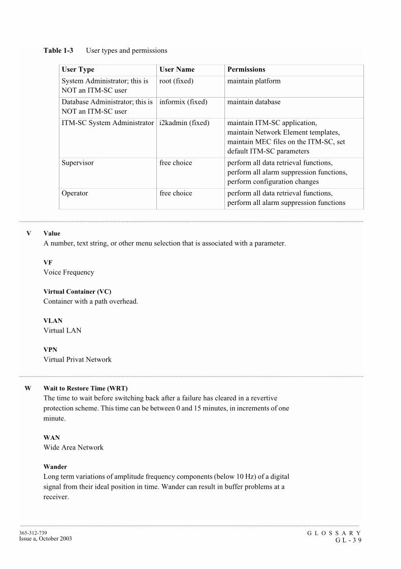
G L O S S A R YG L - 3 9
365-312-739Issue a, October 2003
...........................................................................................................................................................................................................................................................
...............................................................................................................................................................................................................................................................
...............................................................................................................................................................................................................................................................
Table 1-3 User types and permissions
V Value
A number, text string, or other menu selection that is associated with a parameter.
VF
Voice Frequency
Virtual Container (VC)
Container with a path overhead.
VLAN
Virtual LAN
VPN
Virtual Privat Network
W Wait to Restore Time (WRT)
The time to wait before switching back after a failure has cleared in a revertive protection scheme. This time can be between 0 and 15 minutes, in increments of one minute.
WAN
Wide Area Network
Wander
Long term variations of amplitude frequency components (below 10 Hz) of a digital signal from their ideal position in time. Wander can result in buffer problems at a receiver.
User Type User Name Permissions
System Administrator; this is NOT an ITM-SC user
root (fixed) maintain platform
Database Administrator; this is NOT an ITM-SC user
informix (fixed) maintain database
ITM-SC System Administrator i2kadmin (fixed) maintain ITM-SC application,maintain Network Element templates, maintain MEC files on the ITM-SC, set default ITM-SC parameters
Supervisor free choice perform all data retrieval functions,perform all alarm suppression functions, perform configuration changes
Operator free choice perform all data retrieval functions,perform all alarm suppression functions
G L O S S A R YG L - 4 0
365-312-739Issue a, October 2003
.........................................................................................................................................................................................................................................................
............................................................................................................................................................................................................................................................
WaveStar® Integrated Transport Management Subnetwork Controller (ITM-SC)
Manager for SDH network elements in a subnetwork. Also called an Element Management System.
WaveStar® Network Management System (NMS)
Manager for SDH network elements in a network. Formerly known as DACScan-T.
WDM
Wavelength Division Multiplexing
What You See Is What You Get (WYSIWYG)
Information as displayed on the screen will appear in the same way on printed output.
Wideband Communications
Voice, data, and/or video communication at digital rates from 64 kbit/s to 2 Mbit/s.
Windows
Graphical User Interface on PC systems.
Working
Label attached to a physical entity. Inthe case of revertive switching the working line or unit is the entity that carry service under normal operation. In the case of non-revertive switching this label has no particular meaning.
WS
WorkStation
WSF
Work Station Facility
X XMTR
Transmitter
XMTR Switch Unit
Radio Relay circuit pack that performs connections for protection switching and transmission of low priority traffic on the protection channel.
XPIC
Cross Polarization Interference Cancellation
XSU
XMTR Switch Unit
X-Terminal
Workstation that can support an X-Windows interface

G L O S S A R YG L - 4 1
365-312-739Issue a, October 2003
...........................................................................................................................................................................................................................................................

G L O S S A R YG L - 4 2
365-312-739Issue a, October 2003
.........................................................................................................................................................................................................................................................