Adjustable pushrod suspension system - UC DRC Home
42
Adjustable Pushrod Suspension System by ANDREW BAYER Submitted to the MECHANICAL ENGINEERING TECHNOLOGY DEPARTMENT In Partial Fulfillment of the Requirements for the Degree of Bachelor of Science m MECHANICAL ENGINEERING TECHNOLOGY at the OMI College of Applied Science University of Cincinnati May2009 © ...... Andrew Bayer The author hereby grants to the Mechanical Engineering Technology Department permission to reproduce and distribute copies of this thesis document in whole or in part. Accepted by Muthar Al-Ubmd1, , Department Head Mechanical Engineering Technology
Transcript of Adjustable pushrod suspension system - UC DRC Home

Adjustable Pushrod Suspension System
by
ANDREW BAYER
Submitted to the MECHANICAL ENGINEERING TECHNOLOGY DEPARTMENT
In Partial Fulfillment of the Requirements for the
Degree of
Bachelor of Science m
MECHANICAL ENGINEERING TECHNOLOGY
at the
OMI College of Applied Science University of Cincinnati
May2009
© ...... Andrew Bayer
The author hereby grants to the Mechanical Engineering Technology Department permission to reproduce and distribute copies of this thesis document in whole or in part.
Accepted by Muthar Al-Ubmd1, , Department Head Mechanical Engineering Technology
Adjustable Pushrod Suspension Design
Andrew Bayer
University of Cincinnati OCAS, MET
June 1, 2009
Prof. Amir Salehpour

i
TABLE OF CONTENTS
TABLE OF CONTENTS ........................................................................................................... I
LIST OF FIGURES .................................................................................................................. II
LIST OF TABLES .................................................................................................................... II
ABSTRACT .............................................................................................................................. 1
1 - INTRODUCTION ............................................................................................................... 2
2 - CURRENT CATERHAM SUSPENSION PROBLEMS .................................................... 3
3 - CURRENT SUSPENSION DESIGNS ............................................................................... 4
4 - PUSHROD SUSPENSION DISCUSSION ......................................................................... 5
5 - CUSTOMER NEEDS ......................................................................................................... 6
6 - PRODUCT OBJECTIVES .................................................................................................. 7
7 - ALTERNATIVE DESIGNS................................................................................................ 8
8 - DESIGN SELECTION ...................................................................................................... 11
9 - CALCULATING NATURAL FREQUENCY OF THE SUSPENSION.......................... 12
10 - SUSPENSION LOADING CONDITIONS .................................................................... 13 10.1- LOWER CONTROL ARM LOADING ........................................................................... 13
10.2- PUSHROD LOADING ..................................................................................................... 14
10.3- BELLCRANK LOADING ................................................................................................ 15
11 – FABRICATION AND ASSEMBLY .............................................................................. 16
12 - DESIGN TESTING……………………………………………………………………..16
13 – DESING SCHEDULE .................................................................................................... 19
14 - BUDGET PLAN.............................................................................................................. 19
REFERENCES ....................................................................................................................... 20
APPENDIX A - RESEARCH ................................................................................................ A1
APPENDIX B - SURVEY ...................................................................................................... B1
APPENDIX C - QUALITY FUNCTION DEPLOYMENT (QFD) ....................................... C1
APPENDIX D - WEIGHTED DECISION METHOD TABLE ............................................ D1
APPENDIX E - BILL OF MATERIALS ............................................................................... E1
APPENDIX F – LOADING CALCULATIONS .................................................................... F1
APPENDIX G – ASSEMBLY DRAWINGS ........................................................................ G1
APPENDIX H - BUDGET .................................................................................................... H1
APPENDIX I - DESIGN SCHEDULE……………………………………………………....I1

ii
LIST OF FIGURES Figure 1- Caterham………………………………………………………………………. 2 Figure 2- Caterham Suspension Detail and Coil-Over Angle…………………………… 3 Figure 3- Camber Explanation………………………………………………………….... 4 Figure 4- Unequal Length Double Wishbone Suspension………………………………. 5 Figure 5- Design Concept 1 Standard Suspension………………………………………. 8 Figure 6- Design Concept 2- Pullrod Suspension……………………………………….. 9 Figure 7- Design Concept 3- Pushrod Suspension………………………………………. 10 Figure 8- Completed Pushrod Suspension Design………………………………………. 11 Figure 9- Unloaded suspension sitting at ride height……………………………………. 17 Figure 10- Firm suspension setting with 200 lb static load…………………….………... 17 Figure 11- Soft suspension setting with 200 lb static load.............………………….…... 17 Figure 12- Screenshot taken from ride quality testing video…………………….………. 18
LIST OF TABLES Table 1- QFD Results……………………………………………………………………. 6 Table 2- Pushrod Mounting Point Comparison………………………………………….. 12

Adjustable Pushrod Suspension Design Andrew Bayer
1
ABSTRACT The Caterham is a type of car used mostly for everyday driving, but also for occasional trips to the racetrack. This requires a suspension design that is both road friendly but also able to give the handling characteristics needed for track use. The car itself is a lightweight kit car that unfortunately has an inefficient suspension design where the spring and shock assembly is mounted at an extreme angle due to the low ride height and lack of space. Currently to remedy this, much higher spring rates must be used to compensate for the reduced spring efficiency, which results in a very firm and uncomfortable ride quality. Therefore an adjustable pushrod style suspension was designed, like that of open wheel racecars. Modifying this design allowed for adjustability of ride quality without the need to dismantle the suspension to change spring rates. This design allows the driver to have separate settings for ride quality, a softer and more comfortable feeling suspension with better ride quality while driving on the street, as well as a firmer setting that allows for betting handling during track driving. The suspension passed a static loading test to make sure that the settings fell between current industry standards for ride quality. Qualitative testing was also done to make sure that people could feel a difference in ride quality between the firm and soft settings.

Adjustable Pushrod Suspension Design Andrew Bayer
2
1- INTRODUCTION Light and fast are two important characteristics of a great track car, and both can be achieved fully with a Caterham kit car. A Caterham, shown in Figure 1, is a very small and extremely lightweight car that can be purchased fully built, as a kit or be pieced together by the individual builder. Due to reduced cost of building a Caterham from scratch, there is always a rather large group of builders working to design and build their own custom cars. However many people end up confused about designing a correctly functioning suspension for their car. The suspension and handling are one of the most important features of a car of this nature because it utilizes only a small four-cylinder engine that does not produce high levels of horsepower. This means that the suspension and ability to adjust to any condition that the car will encounter is absolutely necessary to maintain the quickness that Caterham cars are famous for around the world.
Figure 1- Caterham

Adjustable Pushrod Suspension Design Andrew Bayer
3
2 - CURRENT CATERHAM SUSPENSION PROBLEMS Currently the mounting positions of the double wishbone type suspension on a Caterham car is flawed because of the extreme angles that the spring and shock assembly must be mounted due to the cars low ride height and lack of space for the suspension. This leads to many disadvantages in terms of performance, reliability and adjustment of suspension parts. Also a spring’s effectiveness is proportional to how close to 90˚ it can be mounted between the upper and lower control arms (2). Because of the angle that the spring and shock assembly must be mounted, as shown in Figure 2, higher spring rates are required to compensate for the loss of effectiveness in the spring and damper. This inadequately transmits more of the forces that the tires encounter into the frame itself rather than absorbing and damping them using the suspension. This suspension setup translates to a good handling car with an extremely harsh ride quality. In comparison, if the softer spring were left in, a softer ride quality would be felt, but there would also be a lack of performance in the handling characteristics of the car. As for the adjustability of the current Caterham suspension components, there is only the ability to slightly change the cars ride height by utilizing a coil-over spring and shock assembly, as well as a slight change of camber. To achieve different handling characteristics or ride quality, the spring and shock assembly must be removed and the spring changed with a different spring rate. While this may be okay for a racing team that has the resources to keep an entire stock of springs with different spring rates available, it is unrealistic for the average weekend racer. Therefore, builders and designers are constantly looking for different ways to allow the drivers to have more adjustability in their suspension setups.
45˚
Figure 2- Caterham Suspension Detail, Spring and Shock Angle

Adjustable Pushrod Suspension Design Andrew Bayer
4
3 - CURRENT SUSPENSION DESIGNS Suspension designs found on today’s street driven passenger cars use everything from the simplistic leaf springs to the complicated electric motors and electromagnets to dampen the forces that the wheels and frame see. Most automotive manufacturers design their car’s suspensions to be on the softer side to increase ride comfort, while track and sports cars use firmer suspension setups to achieve the levels of performance and handling needed for the increased speeds, down force and cornering loads. Suspension is possibly the most important component on a car because it has to be able to keep the tire in contact with the road while encountering any type of forces including potholes and speed bumps. Most passenger cars on the market today use a form of the double wishbone, McPherson strut or multilink suspension design (see Appendix A). Everyday passenger cars use these types of suspensions when standard handling performance is desired, as well as space and cost are taken into account. Whereas most high performance sports cars today utilize a type of unequal length double wishbone design (1). This type of suspension design is suited well for track use because it allows for greater adjustment and can be set up to achieve negative camber to accommodate the roll that a car encounters during hard cornering. By using a shorter upper control arm and the correct suspension geometry, the tire will actually gain negative camber as the cornering forces increase, therefore increasing its cornering ability. Figure 3 shows how designing a suspension to have the correct amount of negative camber will allow for the tire to roll through a turn and increase the contact patch of the tire to the road. The pushrod and pullrod suspension designs are used mostly among open wheel race cars because of the aerodynamic and adjustability advantages it gives. When researching types of suspensions used in the highest forms of motorsports, such as Formula 1 and Indy Car racing it is known that the proven design is a type of inboard pushrod suspension when space is limited and the shock cannot be mounted in the most beneficial location. Opposed to the normal type outboard suspension, the inboard design transmits the wheel forces through a pushrod and bellcrank to transfer the motion of the wheel to an inboard mounted spring and shock assembly.
Figure 3- Camber Explanation

Adjustable Pushrod Suspension Design Andrew Bayer
5
4 - PUSHROD SUSPENSION DISCUSSION Formula 1 and Indy Car racing is technologically the most advanced form of racing in the world. Therefore, the same concepts that are currently being used for suspension design are constantly being applied to different racing applications such as the Caterham track car to improve performance. Currently most Caterhams come with a type of unequal length double wishbone suspension set up as shown in Figure 4. This is not the case however with a Formula 1 pushrod suspension design. These cars cannot use the standard outboard spring and shock assembly because aerodynamic drag is a major concern when racing at high speeds. Like the Caterham, open wheel race cars have such a low ride height that the spring and shock assembly would have to be mounted at an even lower angle than in a Caterham. Therefore a pushrod style suspension is utilized so that the spring and shock assembly and bellcrank can be mounted at any position that will better dampen the large wheel loads that are seen during racing. This design also reduces the car’s drag by moving the spring inboard the frame. The pushrod suspension also gives easy adjustability because of the different motion ratios that can be changed by adjusting the distances that the pushrod and spring and shock assembly are mounted from the pivot point of the bellcrank itself. Changing these mounting locations effectively changes the ratio of wheel movement to spring compression, whereby changing this ratio different handling characteristics can be seen.
Figure 4- Unequal Length Double Wishbone Suspension

Adjustable Pushrod Suspension Design Andrew Bayer
6
5 - CUSTOMER NEEDS In order to specify some specific details about suspension designs, a survey was sent to a number of race mechanics, race team members, drivers and Caterham enthusiasts; this helped to show what the most important issues were in a suspension design (see Appendix B). The results showed that the most emphasis was on the reliability and safety of the suspension and all of its components, so they would not fail under the worst road conditions that the car could encounter. Next on the list of importance was the multiple adjustability characteristics and ease of access to the suspension to make the necessary adjustments. These were the main design criteria that needed to be met to achieve a successful design according to the survey results.
The Quality Function Deployment (QFD), results shown in Table 1, for the pushrod suspension design showed similar results as that of the survey. The highly weighted areas of the design were that of safety at 12.8% and reliability at 11.7%, with adjustability of spring rate close behind at 11.4%. It also showed that the material used in the design and the loading of the suspension members was to be the most important engineering characteristics with importance values of 12.55 and 10.05 respectively.
Table 1- QFD Results
Performance & Features
Relative Weights
Reliability 12.8%
Safety 11.7%
Adjustability of ride quality
11.4%
Accessibility for adjustments
11.2%
Adjustability of ride height
10.8%
Suspension geometry
9.1%
Reducing unsprungmass
8.9%
Compactness ofdesign
8.7%
Ease of installation 8.0%
Adaptability to different chassis
7.4%

Adjustable Pushrod Suspension Design Andrew Bayer
7
6 - PRODUCT OBJECTIVES This is a compiled list of the product objectives and how they were to be achieved or tested to ensure that project goals were met and the project was successful. The project objectives focused on the adjustable pushrod suspension design of a custom built car that would have a soft suspension setting as well as a firm suspension setting. Adjustability of ride quality -Suspension has two settings for ride quality, a soft setting for street use and a firm
setting for track use. -By adding a weight equal to the sprung mass of the car and measuring the static
deflection, the Natural Frequency could be calculated and must fall between the following ranges.
-60 to 90 CPM Soft ride quality, Street use -120 to 200 CPM Stiff ride quality, Track use -By designing an adjustable bellcrank with different mounting locations for the pushrod
to attach, these ranges were achieved. -Qualitative testing was also done do determine if persons riding in the car could tell a
difference in the two separate ride quality settings. Safety and reliability of suspension components -All suspension components were designed to meet the industry standards of 5 G’s shock
loading on any wheel. Accessibility to components for adjustment -All suspension links and adjustment points were designed to give enough room for an
average sized human hand or the needed adjustment tool to fit and work properly through its range of motion.
Compactness of design -The spring and shock assembly as well as most of the bellcrank were designed to be
fully housed within the body of the car, leaving only the upper and lower control arms and pushrods being the only suspension links visible from the exterior of the car.

Adjustable Pushrod Suspension Design Andrew Bayer
8
7 - ALTERNATIVE DESIGNS Three suspension designs were compared to come up with the ideal suspension setup for the Caterham to be used as a street car as well as a track car. The unequal length double wishbone suspension geometry of the actual suspension links themselves were predetermined using geometric methods and was kept constant when comparing the mounting locations of the spring and shock and the bellcrank assembly. Design Option 1, shown in Figure 5, is the standard placement of the spring and shock assembly used in most vehicle suspension designs on the road today. The spring and shock assembly are mounted as close to vertical as possible while still mounting between the lower control arm and the frame of the car. However, Figure 5 shows that to reduce the bending load on the lower control arm the bottom of the spring and shock assembly is mounted as close to the wheel, which gives the unfavorable angle that was explained earlier. This is not as large of a problem in standard passenger cars because the upper mounting location for the spring and shock assembly is able to me mounted much higher in the car to reduce the mounting angle and keep it closer to the more effective 90˚ position.
Design 1 Standard Suspension
Figure 5- Design Concept 1 Standard Suspension

Adjustable Pushrod Suspension Design Andrew Bayer
9
Design Option 2, shown in figure 6, is a pull rod suspension design used on some open wheel race cars. In this design the spring and shock assembly is mounted inboard of the frame and are placed horizontally. The spring forces of the wheel movement are transferred to the spring via a bellcrank that is mounted low in the frame. The bellcrank is actuated by a pullrod that connects the bellcrank to the upper control arm in this case. This design allows for the center of gravity of the suspension to be very low in the car and can improve performance. However, the problem with a pullrod suspension is that all the forces transmitted through the suspension parts put the components is tension, which is the loading condition that most welded joints will fail. Another problem that is specific to this application is that by mounting the bellcrank at this point on the frame will fully encase the bellcrank within the bodywork and would make it difficult to have easy access to the ride quality adjustment.
Design 2 PullrodSuspension
Figure 6- Design Concept 2- Pullrod Suspension

Adjustable Pushrod Suspension Design Andrew Bayer
10
Design Option 3, shown in Figure 7, is a pushrod suspension design used on open
wheel race cars and in applications where space is limited. This design is similar to the pullrod design in that it also transmits the forces that the suspension sees remotely through a bellcrank. In this case however rather than a pullrod, there is a pushrod that is connected to the lower control arm and to the bellcrank. When the tire hits a bump the force is transmitted through the pushrod, causing the bellcrank to pivot and compress the spring that is mounted inboard the frame. This design does raise the center of gravity slightly, but is more beneficial to this application because it puts the links in compression and there will be less of a chance for the welds to fail. The pushrod suspension also places the bellcrank at an optimal position that will put the mounting locations for ride quality just outside the body work, and more accessible than in the other designs.
Design 3 Pushrod Suspension
Figure 7- Design Concept 3- Pushrod Suspension

Adjustable Pushrod Suspension Design Andrew Bayer
11
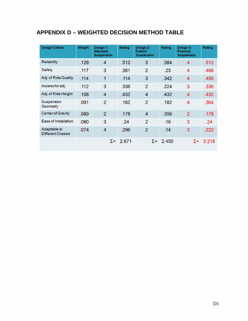
8 - DESIGN SELECTION After choosing the three most likely designs that could be used for this application, a 5-point weighted decision method (see Appendix D) was utilized to choose the best design concept. Completing the weighted decision method showed that all three designs yielded similar ratings because each has its own advantages and disadvantages. The standard suspension design received a rating of 2.67, the pullrod suspension design received a rating of 2.45 and the pushrod suspension design received a rating of 3.22. The pushrod suspension, shown in Figure 8, was decided to be the best design concept for the application because of its ability to transmit the most force seen from tire movement directly into the spring rather than into the frame. The pushrod suspension design also provided the best design for ease of adjustability by utilizing the adjustable bellcrank so that the suspension motion ratios can be changed to achieve the different suspension settings for ride quality.
Figure 8- Completed Pushrod Suspension Design
Adjustable Pushrod Suspension Design Andrew Bayer
12
9 - CALCULATING NATURAL FREQUENCY OF THE SUSPENSION
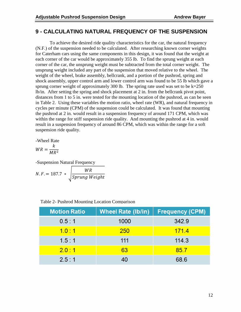
To achieve the desired ride quality characteristics for the car, the natural frequency (N.F.) of the suspension needed to be calculated. After researching known corner weights for Caterham cars using the same components in this design, it was found that the weight at each corner of the car would be approximately 355 lb. To find the sprung weight at each corner of the car, the unsprung weight must be subtracted from the total corner weight. The unsprung weight included any part of the suspension that moved relative to the wheel. The weight of the wheel, brake assembly, bellcrank, and a portion of the pushrod, spring and shock assembly, upper control arm and lower control arm was found to be 55 lb which gave a sprung corner weight of approximately 300 lb. The spring rate used was set to be k=250 lb/in. After setting the spring and shock placement at 2 in. from the bellcrank pivot point, distances from 1 to 5 in. were tested for the mounting location of the pushrod, as can be seen in Table 2. Using these variables the motion ratio, wheel rate (WR), and natural frequency in cycles per minute (CPM) of the suspension could be calculated. It was found that mounting the pushrod at 2 in. would result in a suspension frequency of around 171 CPM, which was within the range for stiff suspension ride quality. And mounting the pushrod at 4 in. would result in a suspension frequency of around 86 CPM, which was within the range for a soft suspension ride quality. -Wheel Rate
-Suspension Natural Frequency
Table 2- Pushrod Mounting Location Comparison

Adjustable Pushrod Suspension Design Andrew Bayer
13
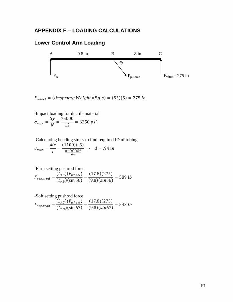
10 - SUSPENSION LOADING CONDITIONS 10.1 Lower Control Arm Loading The suspension was an example of an area on the car where it was better to be overdesigned than to be close to the designed factors of safety. An industry standard for suspension design is to design for the worst-case scenario of 5g’s acceleration directed into the tire. In this case the loading condition turned out to be 275 lb per wheel. In the free body diagram of the lower control arm, A is the mounting location of the control arm to the frame, B is the mounting location of the pushrod and C is the effective center of the wheel where the force would be applied. After completing the shear and moment diagrams for the lower control arm, the force transmitted to the pushrod as well as the maximum bending moment could be found. The force transmitted into the pushrod was calculated to be 589 lb for the firm suspension setting at 543 lb for the soft suspension setting. The maximum bending moment for each tube in the lower control arm was found to be 1100 in-lb. The maximum bending stress for 3140 Chrome Moly under impact loading was found to be 6250 psi. Using these values and setting the outside diameter of the tubing to be 1 in. the inside diameter of the tubing was found to be .94in. The closest standard size tubing available was 1” OD x .065” wall thickness. The increased tubing thickness above the required specifications will add even more to the factor of safety in the lower control arm. Calculations can be found in Appendix F.
FA
Fpushrod
Θ
Fwheel= 275 lb
C 8 in.
9.8 in. A B

Adjustable Pushrod Suspension Design Andrew Bayer
14
10.2 - Pushrod Loading Using the maximum loading of 589 lb for the pushrod in the firm suspension setting, the critical buckling load was needed to make sure that the pushrod was designed with an adequate factor of safety. The k factor, slenderness ratio and column constant was found and compared to find that the column was considered to be short. Therefore the Johnson formula was used to find that the critical buckling load of the column was 13136 lb. Comparing these values yielded a factor of safety that was well above shock loading.
Fpushrod= 589 lb
12 in.
Fbellcrank= 589 lb
Adjustable Pushrod Suspension Design Andrew Bayer
15
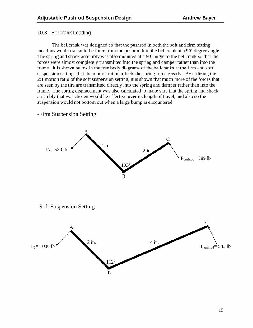
10.3 - Bellcrank Loading The bellcrank was designed so that the pushrod in both the soft and firm setting locations would transmit the force from the pushrod into the bellcrank at a 90˚ degree angle. The spring and shock assembly was also mounted at a 90˚ angle to the bellcrank so that the forces were almost completely transmitted into the spring and damper rather than into the frame. It is shown below in the free body diagrams of the bellcranks at the firm and soft suspension settings that the motion ration affects the spring force greatly. By utilizing the 2:1 motion ratio of the soft suspension setting, it is shown that much more of the forces that are seen by the tire are transmitted directly into the spring and damper rather than into the frame. The spring displacement was also calculated to make sure that the spring and shock assembly that was chosen would be effective over its length of travel, and also so the suspension would not bottom out when a large bump is encountered. -Firm Suspension Setting -Soft Suspension Setting
2 in.
2 in.
103º
A
B
C
Fpushrod= 589 lb
FS= 589 lb
112º
2 in.
4 in.
C
B
A
Fpushrod= 543 lb FS= 1086 lb

Adjustable Pushrod Suspension Design Andrew Bayer
16
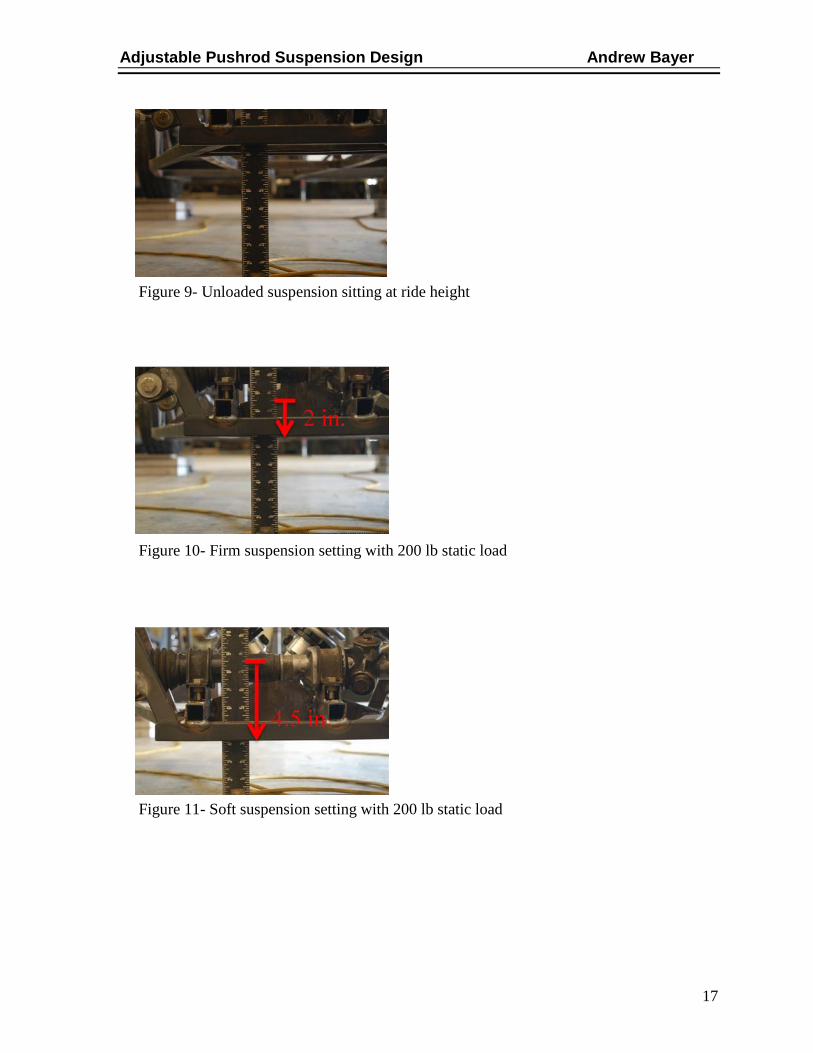
11 - FABRICATION AND ASSEMBLY Fabrication of the suspension components was driven by the calculations for the tubing thickness required for the 5 G shock loading condition. Once the suspension was modeled using SolidWorks, drawings for the components could be generated and dimensioned. Using these drawings the suspension tubing was cut to length and notched to allow for easier welding of the round tubing. All suspension mounting brackets were cut to the drawing specifications using a CNC plasma cutter to achieve a high tolerance and consistency in the parts being manufactured. All suspension pieces were TiG welded together so that heat could be accurately controlled to minimize warping and allow for a stronger weld. After the suspension components had been fabricated, spherical rod ends were used at all the suspension end links which gave the suspension nearly unlimited adjustability. Corner scales, camber gauges and toe plates were utilized to setup and align the suspension. After some rolling testing, the suspension alignment was optimized so that the car was rolling perfectly straight. To adjust the ride quality a jack was placed under the front frame rail of the car to take all the compression forces out of the springs, which in turn allowed for the pushrod mounting location to be easily unbolted and changed by one person. 12 - DESIGN TESTING To make sure the suspension worked effectively, both qualitative and quantitative testing was completed. First, a static load test was used to calculate the natural frequency of the suspension to see if the two suspension settings were within the specified ranges for soft and firm suspension ride quality. A ride quality test was also completed, to prove that a difference could be felt between the soft and firm suspension settings. For the static load test, a 200 lb load, which was equal to the sprung weight of the car’s frame, was placed above the front suspension. By adding a weight equal to the sprung weight of the car, the static deflection of the frame displaced downward could be recorded and used to solve for the natural frequency of the suspension using the equation below. Figure 9 shows the suspension sitting at ride height before testing. After the 200 lb load was applied, the firm suspension deflected 2 in., shown in Figure 10. With 2 in. of deflection the natural frequency was calculated to be 133 CPM, which was within the firm frequency ranges of 120 – 200 CPM. Figure 11 shows that the static deflection for the soft suspension under the 200 lb static load was 4.5 in. This translated to a suspension natural frequency of 88 CPM, which was within the soft frequency ranges of 60 – 90 CPM.
Adjustable Pushrod Suspension Design Andrew Bayer
17
Figure 9- Unloaded suspension sitting at ride height
Figure 10- Firm suspension setting with 200 lb static load
Figure 11- Soft suspension setting with 200 lb static load

Adjustable Pushrod Suspension Design Andrew Bayer
18
To test the ride quality settings, a group of test subjects were assembled from people who had previously filled out the pushrod suspension survey. The test group included race car mechanics and Caterham enthusiasts. Before explaining the workings of the pushrod suspension, each subject sat in the driver’s seat of the car and the car was run over a 2 in. bump in the road at a constant speed as seen in Figure 12. The suspension was then changed to the opposite setting and the test run again so that the test subject could have a comparison suspension setting. Thus far four out of four test subjects could correctly tell the firm suspension setting from the soft suspension setting.
Figure 12- Screenshot taken from ride quality testing video
Adjustable Pushrod Suspension Design Andrew Bayer
19
13 - DESIGN SCHEDULE The design, fabrication and assembly were completed by the final deadline date of the 2009 OCAS Tech Expo on May 7th. The major part of Senior Design 1 was the actual design of the suspension geometry so that everything would function correctly. The preliminary design of the suspension was completed by Feb. 4th. Originally the schedule was planned to design each of the parts separately over the course of a few weeks. However, these plans were flawed because the designs of all the suspension parts were complimentary to each other and were unable to be designed separately. The largest part of Senior Design 2 was the fabrication of the suspension components and was completed by April 20th. The fabrication took slightly longer than originally planned because of all the extra components that had to be fabricated so that the suspension could work properly. This included the extra fabrication of the rear suspension and steering for the front wheels. The project was then assembled and testing of the suspension lasted until May 23 because of the need for safety equipment that had to be installed to perform the ride quality testing. The project was presented at the 2009 OCAS Tech Expo on May 7th. Following the completion of the Senior Design 2 presentation on May 26th and the final paper deadline of June 1, the Adjustable Pushrod Suspension Design Project met all of the required goals. See Appendix I for a full design schedule breakdown. 14 - BUDGET PLAN The budget for the pushrod suspension assembly can be split into two major parts, the raw material and the purchased components. The raw material included the steel that was used for the fabrication of the suspension links, mounting tabs, and bellcranks and was estimated based on current material cost to be approximately $110. The purchased components being the larger portion of the budget were estimated to cost approximately $970. This in turn gave a final estimated cost for the entire pushrod suspension assembly to be $1080. After purchasing all the material and components that were necessary for the fabrication and assembly of the suspension, the final cost of the assembly was $751. The difference in the budget came from finding that the material prices had originally been slightly underestimated, while some of the purchased components had been overestimated. Labor cost was not estimated for the fabrication and assembly of the components, but factoring this in would keep the total assembly cost within the ranges that the customer survey results showed to be a reasonable price for a pushrod suspension assembly.
Adjustable Pushrod Suspension Design Andrew Bayer
20
REFERENCES 1. Longhurst, Chris. The Suspension Bible. The Car Maintenence Bibles. [Online] 1994-2008. [Cited: September 4, 2008.] http://www.carbibles.com/suspension_bible.html. 2. Adams, Herb. Chassis Engineering. New York : The Berkley Publishing Group, 1993. 3. Haney, Paul. Photos from a Phoenix Test. Inside Racing Technology. [Online] March 3, 1999. [Cited: September 23, 2008.] http://www.insideracingtechnology.com/phnxtst.htm.

A1
APPENDIX A - RESEARCH
The transverse leaf spring suspension is an older design that uses either a trailing arm or one control arm, and the other control arm is effectively a leaf spring that is mounted transverse across the body of the car. It can act like a independent suspension in some cases because the center of the leaf spring is bolted to the frame of the car and each end acts independent of the other. However, the wheels are still connected by a single link. An advanced form of this design is used today on the new Chevrolet Corvettes, but if the car is used for racing the leaf spring is almost always removed and replaced with a double wishbone and coil spring suspension like the ones above.
-Cheap design -Can act like an independent suspension is designed correctly -Very limited adjustment
http://www.rodtech.com.au/IBEAM%20ASSEMBLY.htm 9/23/08 Transverse Leaf Spring Suspension

A2
Copyright ©1994 - 2008 Christopher J Longhurst. All Rights Reserved
In a trailing arm suspension design there are two larger links that supports the steering knuckle with the spring and shock assembly mounted to one of trailing links and the other end to the frame of the vehicle. The wheel and tire trails behind the links of the suspension, effectively dragging the tires over any obstructions in the road surface.
-Small overall suspension package -Average independent suspension ride comfort and tire to road adhesion -In high cornering load situations and sudden road irregularities the trailing links are subject to very high loading and bending may occur, resulting in vibrations in the suspension and steering -Camber of the wheels changes as the car body rolls through a turn -Extremely heavy and bulky in some cases
www.carbibles.com/suspension_bible.html 9/20/08 Trailing Arm Suspension

A3
The MacPherson strut type suspension is made up of one lower a-arm(control arm) attached to the bottom of the knuckle. The top of the knuckle connects directly to the spring and shock assembly with the other end being attached to the frame of the vehicle. This is mostly used on smaller front wheel drive cars because it allows for a straight shot for the drive axle to the knuckle. Like the trailing arm suspension this design is best suited for production road cars, but is not very performance oriented for a race car.
-Standard advantages of an independent suspension in ride comfort and performance. -Extremely small compact design -Good for use on small front wheel drive(FWD) cars. -Lacks the ability of using a wider tire because of the placement of the spring and shock assembly. -Lacks the ability to gain camber in hard cornering. -Tall design, not able to be used on lower profile race cars.
www.motorera.com/dictionary/car-dica.htm 9/20/08 Typical MacPherson Strut Suspension
A4
Copyright ©1994 - 2008 Christopher J Longhurst. All Rights Reserved
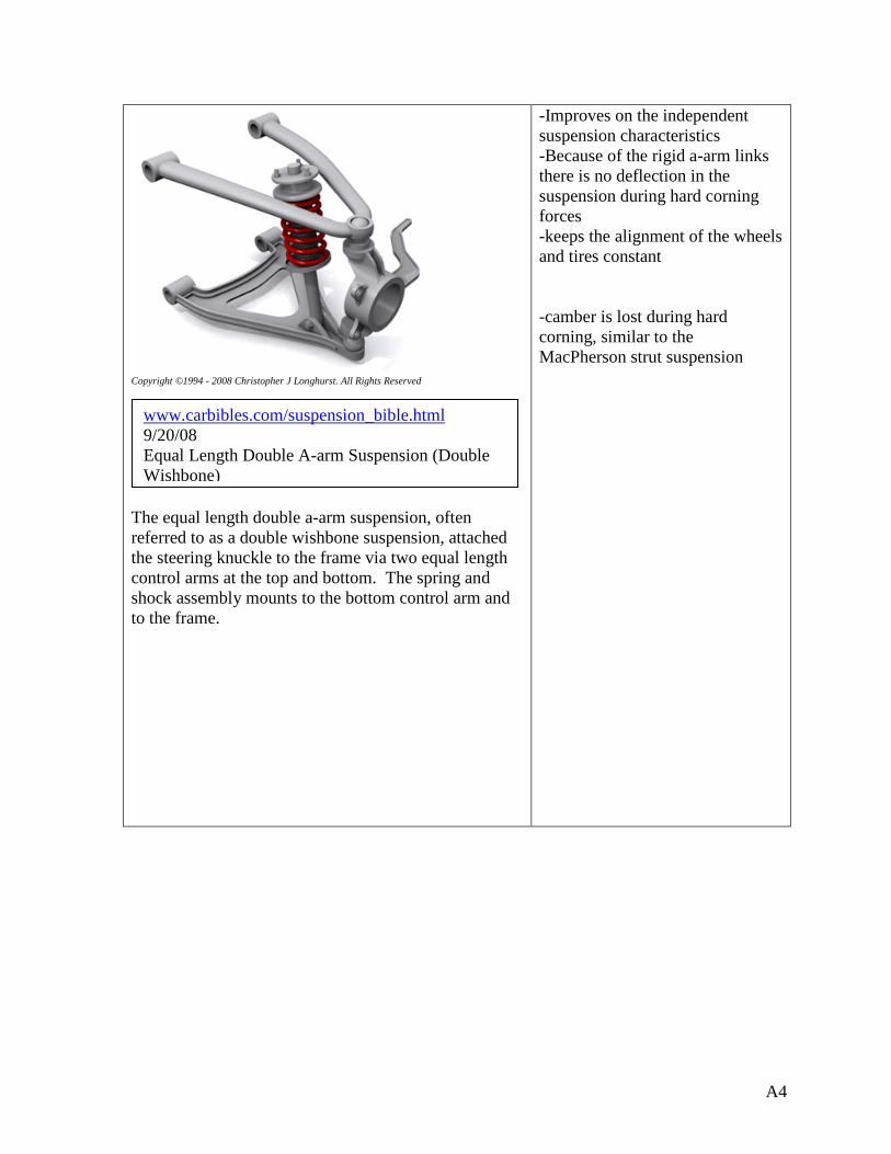
The equal length double a-arm suspension, often referred to as a double wishbone suspension, attached the steering knuckle to the frame via two equal length control arms at the top and bottom. The spring and shock assembly mounts to the bottom control arm and to the frame.
-Improves on the independent suspension characteristics -Because of the rigid a-arm links there is no deflection in the suspension during hard corning forces -keeps the alignment of the wheels and tires constant -camber is lost during hard corning, similar to the MacPherson strut suspension
www.carbibles.com/suspension_bible.html 9/20/08 Equal Length Double A-arm Suspension (Double Wishbone)

A5
The unequal length double a-arm suspension is the same as the design above except that the top a-arm or control arm is shorter than the bottom control arm. This causes the tire to gain negative camber through hard cornering which is ideal for a suspension design. This is the suspension design utilized on most cars from quality manufacturers today.
-Negative camber gain during corning forces -For low profile cars the spring and shock assembly will have to be mounted at an extreme angle. The further from 90 degrees that the shock is mounted the less effective the performance will be -Suspension adjustment can only be made by replacing the springs
http://www.automotivearticles.com/uploads/a-arm_img.jpg 9/20/08 Unequal Length Double A-arm Suspension (Unequal Double Wishbone)

A6
The linear electro magnetic suspension is a design by Bose® that replaces the springs and shocks with linear electromagnetic motors and power amplifiers. When electrical power is applied the motor will extend or retract, which creates the motion between the wheel and the chassis of the car.
-Motor can so fast that almost all vibration caused from inconsistencies in the are not felt in the car -Suspension is able to adapt to hard cornering and firm the correct suspension parts to reduce almost all body roll. -Expensive design -Still in testing phase
www.carbibles.com/suspension_bible.html 9/24/08 Linear Electro Magnetic Suspension

A7
This is an example of a pushrod suspension on an Indy Car. The design utilizes two unequal length control arm to connect the steering knuckle and wheel to the chassis. The spring and shock assembly is not mounted directly to the control arms like in the double wishbone design, but is rather actuated remotely via pushrods and bell cranks.
-Design can be built to achieve a rising spring rate, as the spring compresses during hard cornering -Ease of adjustment in all the links and spring rates -Reduces unsprung weight of the vehicle -any spring rate can be used by changing the bell crank to achieve any desired mechanical advantage
insideracingtechnology.com/phnxtst.htm 9/23/08 Pushrod Suspension used on Indy Cars

A8
The Formula OCAS 2006 team of four MET students designed, built and raced a SCCA autocross car prepared for the A-modified class. The team utilized a pushrod suspension design for their small cars suspension
MET Project Formula OCAS 2006
Interview with Chris Lowe. 9/25/08 [email protected] Mechanic for F1000 open wheel racecar driver Justin Pritchard. Car uses pushrod suspension. To change spring rates according to track and conditions they have to completely swap out springs.
B1
APPENDIX B - SURVEY
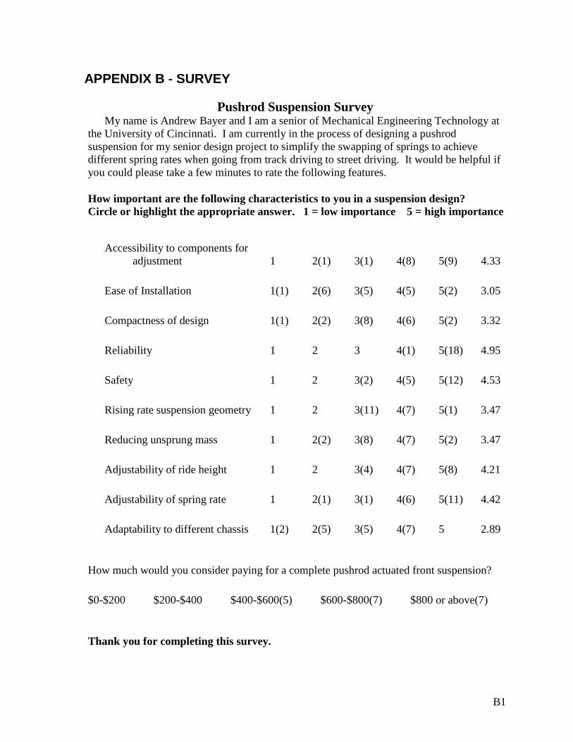
Pushrod Suspension Survey My name is Andrew Bayer and I am a senior of Mechanical Engineering Technology at the University of Cincinnati. I am currently in the process of designing a pushrod suspension for my senior design project to simplify the swapping of springs to achieve different spring rates when going from track driving to street driving. It would be helpful if you could please take a few minutes to rate the following features.
How important are the following characteristics to you in a suspension design? Circle or highlight the appropriate answer. 1 = low importance 5 = high importance
Accessibility to components for adjustment 1 2(1) 3(1) 4(8) 5(9) 4.33
Ease of Installation 1(1) 2(6) 3(5) 4(5) 5(2) 3.05
Compactness of design 1(1) 2(2) 3(8) 4(6) 5(2) 3.32
Reliability 1 2 3 4(1) 5(18) 4.95
Safety 1 2 3(2) 4(5) 5(12) 4.53
Rising rate suspension geometry 1 2 3(11) 4(7) 5(1) 3.47
Reducing unsprung mass 1 2(2) 3(8) 4(7) 5(2) 3.47
Adjustability of ride height 1 2 3(4) 4(7) 5(8) 4.21
Adjustability of spring rate 1 2(1) 3(1) 4(6) 5(11) 4.42
Adaptability to different chassis 1(2) 2(5) 3(5) 4(7) 5 2.89
How much would you consider paying for a complete pushrod actuated front suspension?
$0-$200 $200-$400 $400-$600(5) $600-$800(7) $800 or above(7)
Thank you for completing this survey.

C1
APPENDIX C – QUALITY FUNCTION DEPLOYMENT (QFD)
9 = Strong3 = Moderate1 = Weak
Ove
rall
Siz
e
Wei
ght
Dia
met
er o
f Lin
ks
Mat
eria
l
Sur
face
Fin
ish
Load
ing
Set
up
Cam
ber G
ain
End
links
Use
d
Adj
usta
ble
Coi
love
r Spr
ing/
Sho
ck
Adj
usta
ble
Bel
lcra
nk
Cus
tom
er Im
porta
nce
Rel
ativ
e w
eigh
t
Rel
ativ
e w
eigh
t %
PerformanceAdjustability of spring rate 3 9 4.39 0.11 11.4%Adjustability of ride height 3 4.17 0.11 10.8%Reducing unsprung mass 3 9 9 9 1 1 3.44 0.09 8.9%Adaptability to different chassis 3 1 2.83 0.07 7.4%Suspension geometry 1 1 9 9 3.5 0.09 9.1%
Features
Accesability of components 3 1 1 4.3 0.11 11.2%
Safety 1 3 9 3 1 4.5 0.12 11.7%
Reliability 1 9 9 1 1 1 4.94 0.13 12.8%Compactness of design 9 3 1 3.33 0.09 8.7%Ease of Installation 1 1 3 1 1 3 3 3.06 0.08 8.0%Abs. importance 1.5 1.1 1.5 3.0 0.0 2.4 1.2 0.7 0.2 1.3 38.46 1.00Rel. importance 6.14 4.37 6.27 12.55 0.00 10.05 5.19 2.75 1.00 5.28
Abs. Impt. Total= 12.9
D1
APPENDIX D – WEIGHTED DECISION METHOD TABLE

E1
APPENDIX E – BILL OF MATERIALS
# Description Material Quantity
1 1in x .065 in Tubing 4130 Chrome Moly 130 in
2 QA-1 250 lb/in Springs 2
3 QA-1 Coilover Shocks, 5 in. travel Aluminum 2
4 ½ in Rod End, 12 x 20 RH Thread 4130 Chrome Moly, PTFE 12
5 ½ in Ball Joint, 12 x 20 LH Thread 2
6 12 x 20 RH Threaded Tubing Adapter 4130 Chrome Moly 12
7 12 x 20 LH Threaded Tubing Adapter 4130 Chrome Moly 2
8 ¼ in Sheet Steel 1020 Carbon Steel 80 in^2
9 1/8 in Sheet Steel 1020 Carbon Steel 270 in^2
10 Steering Knuckle Cast Steel 2
F1
APPENDIX F – LOADING CALCULATIONS Lower Control Arm Loading
-Impact loading for ductile material
-Calculating bending stress to find required ID of tubing
-Firm setting pushrod force
-Soft setting pushrod force
FA
Fpushrod
Θ
Fwheel= 275 lb
C 8 in.
9.8 in. A B

F2
Pushrod Loading -Slenderness ratio
-Column constant
-Critical buckling load
Fpushrod= 589 lb
12 in.
Fbellcrank= 589 lb

F3
Bellcrank Loading -Firm Suspension Setting -Force transmitted to spring
-Spring displacement
-Soft Suspension Setting -Force transmitted to spring
-Spring displacement
2 in.
2 in.
103º
A
B
C
Fpushrod= 589 lb
FS= 589 lb
112º
2 in.
4 in.
C
B
A
Fpushrod= 543 lb FS= 1086 lb

G1
APPENDIX G - ASSEMBLY DRAWINGS

H1
APPENDIX H – BUDGET

I1
APPENDIX I – DESIGN SCHEDULE