Adjacent Channel DVB-H Interference into Analogue PAL ... · the audio quality of the signal at...
33
Page 1 of 33 ERA Business Unit: ERA TECHNOLOGY LTD Report Title: Adjacent Channel DVB-H Interference into Analogue PAL Television Author(s): B Randhawa, I Parker Client: Ofcom ERA Report Number: 2007-0581 (Issue 2) ERA Project Number: 7G0403801 Report Version: Final Report ERA Report Checked by: Approved by: Steve Munday Project Manager, RF Group Martin Ganley Head of EMC & RF Group October 2007 Ref. SPM/vs/62/04038/Rep-6180
-
Upload
duongtuyen -
Category
Documents
-
view
216 -
download
0
Transcript of Adjacent Channel DVB-H Interference into Analogue PAL ... · the audio quality of the signal at...

Page 1 of 33
ERA Business Unit: ERA TECHNOLOGY LTD
Report Title: Adjacent Channel DVB-H Interference into Analogue PAL Television
Author(s): B Randhawa, I Parker
Client: Ofcom
ERA Report Number: 2007-0581 (Issue 2)
ERA Project Number: 7G0403801
Report Version: Final Report
ERA Report Checked by: Approved by:
Steve Munday
Project Manager, RF Group
Martin Ganley
Head of EMC & RF Group
October 2007Ref. SPM/vs/62/04038/Rep-6180

ERA Report 2007-0581 (Issue 2)
Ref: S:\CEO\Communications\Publications & Events\Webinfo\Live Sites\New website\Consultations\ConDocs\569 DDR\Reports\ERA1 - ACI DVB-H into PAL TV 2007-0581 (Issue 2).doc
© ERA Technology Ltd
2
© Copyright ERA Technology Limited 2007 All Rights Reserved
No part of this document may be copied or otherwise reproduced without the prior written permission of ERA Technology Limited. If received electronically, recipient is permitted to make such copies as are necessary to: view the document on a computer system; comply with a reasonable corporate computer data protection and back-up policy and produce one paper copy for personal use.
DOCUMENT CONTROL
If no restrictive markings are shown, the document may be distributed freely in whole, without alteration, subject to Copyright.
ERA Technology Ltd Cleeve Road Leatherhead Surrey KT22 7SA UK Tel : +44 (0) 1372 367000 Fax: +44 (0) 1372 367099 E-mail: [email protected]
Read more about ERA Technology on our Internet page at: http://www.era.co.uk/

ERA Report 2007-0581 (Issue 2)
Ref: S:\CEO\Communications\Publications & Events\Webinfo\Live Sites\New website\Consultations\ConDocs\569 DDR\Reports\ERA1 - ACI DVB-H into PAL TV 2007-0581 (Issue 2).doc
© ERA Technology Ltd
3
Summary
As part of the Digital Dividend Review (DDR), ERA was asked by Ofcom to investigate the potential interference of services using digital video broadcast-handheld (DVB-H) into analogue PAL television receivers. Three different types of analogue television were tested:
1. LCD with analogue RF (Receiver 1)
2. Portable television (Receiver 2)
3. Typical home television using a cathode ray tube (CRT) (Receiver 3)
Five different interference cases were investigated based on three different DVB-H bandwidths of 6, 7 and 8 MHz. For three of the cases the DVB-H bandwidths (of 6, 7 and 8 MHz) were centred in a transmission filter of nominally 8 MHz. This was to determine whether DVB-H could minimise interference into PAL by commencing transmissions at a narrower bandwidth, but transition to an 8 MHz bandwidth post digital switch-over without having to change the transmit filters. The remaining two cases investigated assumed that suitable 6 or 7 MHz transmitter filtering was available and that a guard band (of 1 or 0.5 MHz respectively) was therefore created.
These DVB-H signals were used to measure N-1 (channel 37) and N+1 (channel 35) adjacent channel interference into analogue PAL television, using both a non-critical and critical DVB-H transmit filter.
The carrier-to-interference (C/I) ratio was measured using a five-point scale based on Recommendation ITU–R BT.500 [6] to subjectively assess the picture quality of the analogue reception.
From the results shown in Appendix A, it can be concluded that the C/I protection ratios using 6 or 7 MHz transmissions with guard bands created by filtering are similar to those of the DVB-H signal centred in the channel, but using an 8 MHz filter, for both 6 and 7 MHz bandwidths respectively.
When testing for N-1 DVB-H interference, the critical filter was found to improve the initial signal quality for the majority of situations tested compared with the non-critical filter. Also, from the measurement results, the C/I protection ratio improves with respect to a drop from 5 to 4 in the picture quality grade, based on ITU–R BT.500.
The results show that as the bandwidth of the DVB-H is reduced from 8 MHz to 6 MHz, the C/I protection ratio (for a given picture grade):
• Improves by 3 to 5 dB for Receiver 1 using both non-critical and critical filters.

ERA Report 2007-0581 (Issue 2)
Ref: S:\CEO\Communications\Publications & Events\Webinfo\Live Sites\New website\Consultations\ConDocs\569 DDR\Reports\ERA1 - ACI DVB-H into PAL TV 2007-0581 (Issue 2).doc
© ERA Technology Ltd
4
• Improves by 6 dB for Receiver 2 using a non-critical filter and improves between 8 to 12 dB using a critical filter.
• Improves by 1 to 3 dB for Receiver 3 using a non-critical filter and 3 to 6 dB using a critical filter.
For N+1 channel interference, the change in bandwidth does not make such an impact as at N-1, due to the way a PAL analogue demodulator operates (energy in the lower channel will fold-over about the PAL carrier and create unwanted components at comparatively low frequencies where the visual acuity of the eye is greatest).
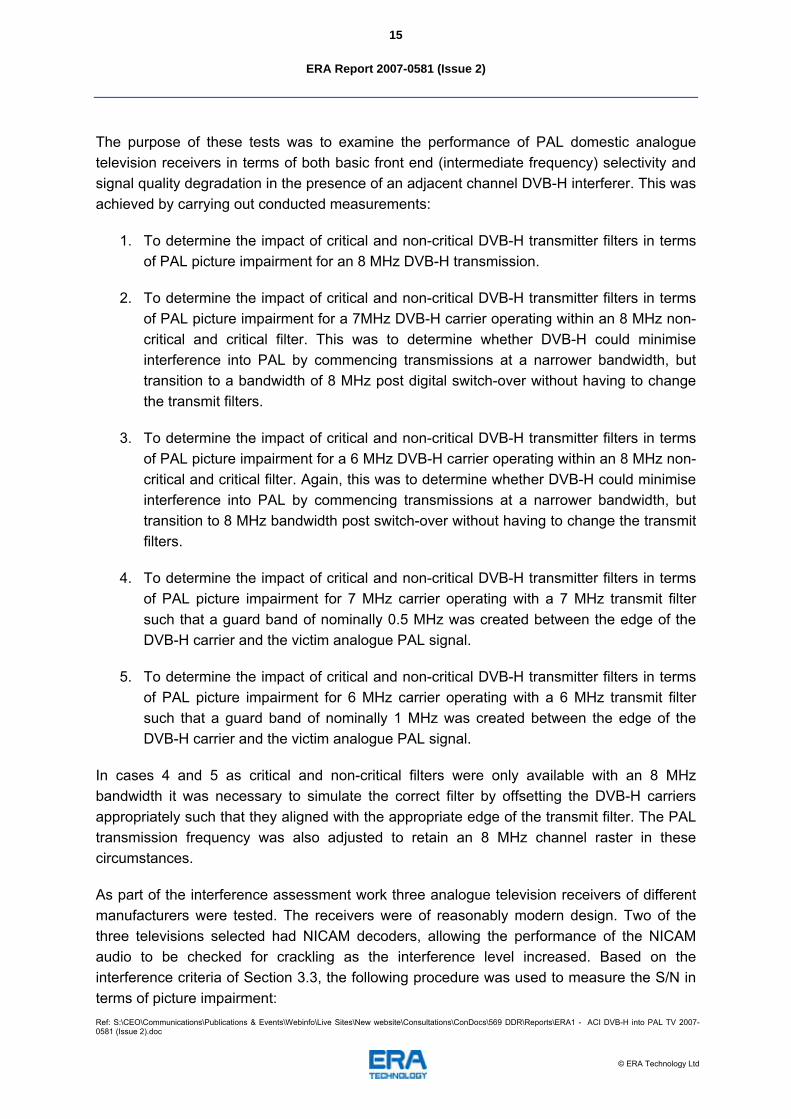
However, the critical filter does improve the C/I protection ratio required for a drop of 5 to 4 in ITU-R scale used to subjectively assess the received picture quality. Also, when testing for the audio quality of the signal at N+1, a distinct crackle or hiss was observed for DVB-H interference producing picture grades of 1 and 2 respectively.
Overall, the results show that Receiver 1 performed the best with regards to adjacent channel DVB-H interference, followed by Receivers 2 and 3 respectively.
If further improvement on the C/I protection ratio results is required, i.e. protection from potential DVB-H interference into analogue PAL television, one of the following must be done:
1. Improve the IF filtering of the analogue PAL television receivers.
2. Improve the filtering of the DVB-H transmit signal.
3. Include a notch filter on channel 36 at the analogue PAL television receive end.
Scenario one would be impractical as many millions of analogue TV sets are already in use and it would be infeasible to change them prior to switch-over. Scenario two is also not a practical proposition because the use of critical filtering already represents a substantial extra degree of cost over non-critical filtering. Further expensive filtering would be impractical given that the analogue PAL receiver intermediate frequency filter response tends to be the dominant factor in determining the overall interference impact in a television receiver.
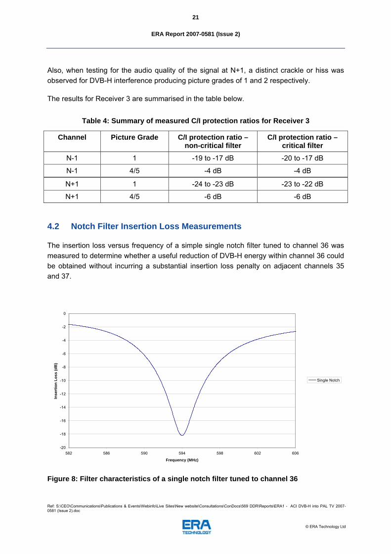
The third solution of using a notch filter at channel 36 (594 MHz) with a band stop rejection around -18 dB may give enough protection to the analogue PAL television from DVB-H interference in certain circumstances, where the analogue signal strength is sufficiently high such that the insertion loss of the filter does not unduly degrade the picture quality.

ERA Report 2007-0581 (Issue 2)
Ref: S:\CEO\Communications\Publications & Events\Webinfo\Live Sites\New website\Consultations\ConDocs\569 DDR\Reports\ERA1 - ACI DVB-H into PAL TV 2007-0581 (Issue 2).doc
© ERA Technology Ltd
5
Contents
Page No.
1. Introduction 9
2. Objectives and Scope of Work 10
3. Test Methodology 11
3.1 Wanted System Parameters 11
3.2 Interfering System Parameters 12
3.3 Interference Criteria 13
3.4 Equipment Set-up and Test Procedure 14
4. Results 16
4.1 Tests using Different DVB-H Bandwidths with Critical and Non-Critical Transmit Filtering 16
4.2 Notch Filter Insertion Loss Measurements 21
5. Conclusions 22
6. Acknowledgements 24
7. References 24
APPENDIX A DVB-H Interference into Analogue PAL Measurement Results 25
A.1 Receiver 1 26
A.2 Receiver 2 28
A.3 Receiver 3 30
APPENDIX B Test Equipment 33
B.1 Test Equipment List 33

ERA Report 2007-0581 (Issue 2)
Ref: S:\CEO\Communications\Publications & Events\Webinfo\Live Sites\New website\Consultations\ConDocs\569 DDR\Reports\ERA1 - ACI DVB-H into PAL TV 2007-0581 (Issue 2).doc
© ERA Technology Ltd
6
Tables List
Page No.
Table 1: DVB-H signal parameters ....................................................................................... 12
Table 2: Summary of measured C/I protection ratios for Receiver 1 .................................... 19
Table 3: Summary of measured C/I protection ratios for Receiver 2 .................................... 20
Table 4: Summary of measured C/I protection ratios for Receiver 3 .................................... 21
Figures List
Page No.
Figure 1: Outline of band plan for 470 – 862 MHz .................................................................. 9
Figure 2: Picture of test card used for assessing picture quality........................................... 11
Figure 3: Typical analogue PAL transmitter signal measured on channel 33....................... 12
Figure 4: Spectrum analyser plot of DVB-H signal with an IP shoulder of -40 dB ................ 13
Figure 5: Measurement set-up of DVB-H interference into analogue TV ............................. 14
Figure 6: Frequency response and return loss of non-critical DVB-H transmit filter ............. 17
Figure 7: Frequency response and return loss of critical DVB-H transmit filter .................... 18
Figure 8: Filter characteristics of a single notch filter tuned to channel 36 ........................... 21
Figure 9: Protection ratios for N-1 DVB-H interference into PAL receiver 1 using a non-critical filter..................................................................................................................... 26
Figure 10: Protection ratios for N-1 DVB-H interference into PAL receiver 1 using a critical filter ................................................................................................................................ 26
Figure 11: Protection ratios for N+1 DVB-H interference into PAL receiver 1 using a non-critical filter..................................................................................................................... 27

ERA Report 2007-0581 (Issue 2)
Ref: S:\CEO\Communications\Publications & Events\Webinfo\Live Sites\New website\Consultations\ConDocs\569 DDR\Reports\ERA1 - ACI DVB-H into PAL TV 2007-0581 (Issue 2).doc
© ERA Technology Ltd
7
Figure 12: Protection ratios for N+1 DVB-H interference into PAL receiver 1 using a critical filter ................................................................................................................................ 27
Figure 13: Protection ratios for N-1 DVB-H interference into PAL receiver 2 using a non-critical filter..................................................................................................................... 28
Figure 14: Protection ratios for N-1 DVB-H interference into PAL receiver 2 using a critical filter ................................................................................................................................ 28
Figure 15: Protection ratios for N+1 DVB-H interference into PAL receiver 2 using a non-critical filter..................................................................................................................... 29
Figure 16: Protection ratios for N+1 DVB-H interference into PAL receiver 2 using a critical filter ................................................................................................................................ 29
Figure 17: Protection ratios for N-1 DVB-H interference into PAL receiver 3 using a non-critical filter..................................................................................................................... 30
Figure 18: Protection ratios for N-1 DVB-H interference into PAL receiver 3 using a critical filter ................................................................................................................................ 30
Figure 19: Protection ratios for N+1 DVB-H interference into PAL receiver 3 using a non-critical filter..................................................................................................................... 31
Figure 20: Protection ratios for N+1 DVB-H interference into PAL receiver 3 using a critical filter ................................................................................................................................ 31

ERA Report 2007-0581 (Issue 2)
Ref: S:\CEO\Communications\Publications & Events\Webinfo\Live Sites\New website\Consultations\ConDocs\569 DDR\Reports\ERA1 - ACI DVB-H into PAL TV 2007-0581 (Issue 2).doc
© ERA Technology Ltd
8
Abbreviations List
DDR
Digital Dividend Review
DTT
Digital Terrestrial Television
DVB-H
Digital Video Broadcast-Handheld
FEC
Forward Error Correction
IF
Intermediate Frequency
IP
Intermodulation Product
PRBS
Pseudo Random Bit Stream
PMSE
Programming Making and Special Events
RF
Radio Frequency
RBW
Resolution Bandwidth
UHF
Ultra High Frequency
UMTS
Universal Mobile Telecommunications System
VBW
Video Bandwidth

ERA Report 2007-0581 (Issue 2)
Ref: S:\CEO\Communications\Publications & Events\Webinfo\Live Sites\New website\Consultations\ConDocs\569 DDR\Reports\ERA1 - ACI DVB-H into PAL TV 2007-0581 (Issue 2).doc
© ERA Technology Ltd
9
1. Introduction
Ofcom announced on 17 November 2005 the beginning of its Digital Dividend Review (DDR) – the project which will examine the options arising from the release of spectrum afforded by the digital switchover program. The available spectrum includes the spectrum released by analogue switch off, the ultra high frequency (UHF) spectrum in bands IV and V (470 – 862 MHz), with the exception of the spectrum reserved for the six digital terrestrial television (DTT) multiplexes [1].
Digital broadcasting is roughly six times more efficient than analogue, allowing more channels to be carried across fewer airwaves. The plans for digital switchover will therefore allow for an increase in the efficiency with which the spectrum is used - including the potential for a large amount of spectrum to be released for wholly new services.
Ofcom estimates that the digital switchover program will release up to approximately 112 MHz of spectrum in the UHF band for new uses. The UHF band is prime spectrum because it offers a technically valuable combination of capacity (bandwidth) and range. This part of the spectrum is much sought after for a whole range of services likely to be used by millions of people every day.
The potential future uses of this spectrum are wide ranging and include: broadband wireless access, cellular mobile (for example, universal mobile telecommunications systems (UMTS) and systems beyond IMT-2000), private mobile radio, further terrestrial digital television services (including standard definition television, high definition television and local digital TV), mobile digital multimedia (including mobile television), and programme making and special events (PMSE).
Figure 1: Outline of band plan for 470 – 862 MHz
The diagram above details the spectrum that will be assigned to six DTT multiplexes post switchover and the spectrum available after switch over.

ERA Report 2007-0581 (Issue 2)
Ref: S:\CEO\Communications\Publications & Events\Webinfo\Live Sites\New website\Consultations\ConDocs\569 DDR\Reports\ERA1 - ACI DVB-H into PAL TV 2007-0581 (Issue 2).doc
© ERA Technology Ltd
10
After switch-over, 14 channels are expected to become completely clear in the UK and available for new uses. New use of channels 31, 40, and 63 have the potential to cause adjacent channel interference to some of the spectrum assigned to the 6 DTT multiplexes. The use of all, but channel 40 of the available spectrum has the potential to cause interference due to the potential N+9 problem. For example, channel 22 has the potential to be interfered with by the use of channel 31 as it is 9 channels away.
Also, were there to be an early release of channel 36 for digital video broadcast – handheld (DVB-H) or similar mobile TV format in a dense network deployment, it is likely that existing Channel 5 analogue transmissions on channel 35 and 37 would suffer interference. Some theoretical assessment work has been carried out to determine the potential impact, but to complement it and to investigate a possible mitigation strategy some practical measurements are necessary. In particular, numerical integration work indicates that the interference level into the PAL receiver from an adjacent channel DVB-H interferer is highly dependent upon the exact characteristics of the filters used and this requires detailed investigation.
As part of the DDR, ERA was asked by Ofcom to investigate the potential interference to digital video broadcast-terrestrial (DVB-T) receivers from UMTS and WiMAX mobile transmitters for adjacent and N+9 channel separation. The results of this initial work were presented in a report to Ofcom in December 2006 [2].
Following on from this work Ofcom commissioned further measurements to characterise the potential interference from DVB-H on channel 36 into analogue PAL transmitting on channel 35 and channel 37.
This report presents the results of conducted measurements to determine the required carrier-to-interference (C/I) protection ratios against frequency separation for adjacent channel DVB-H interference into analogue PAL television.
2. Objectives and Scope of Work
The objective of the work was to enable Ofcom to get a better picture of the performance of DVB-H into analogue PAL television. As there may be an early release of channel 36 for DVB-H or a similar mobile TV format in a dense network deployment it is likely that existing Channel 5 analogue transmissions on channel 35 and 37 would suffer interference.
Some theoretical assessment work has been carried out to determine the potential impact, but to complement it and to investigate a possible mitigation strategy some practical measurements are necessary. In particular, numerical integration work indicates that the interference level into the PAL receiver from an adjacent channel DVB-H interferer is highly dependent upon the exact characteristics of the filters used and this requires detailed investigation [3].

ERA Report 2007-0581 (Issue 2)
Ref: S:\CEO\Communications\Publications & Events\Webinfo\Live Sites\New website\Consultations\ConDocs\569 DDR\Reports\ERA1 - ACI DVB-H into PAL TV 2007-0581 (Issue 2).doc
© ERA Technology Ltd
11
Therefore, conducted measurements to determine the required C/I protection ratios against frequency separation for adjacent channel DVB-H interference into analogue PAL television were carried out.
3. Test Methodology
3.1 Wanted System Parameters
A Philips PM 5418TXS colour TV pattern generator was used to create the wanted analogue PAL-I signal. The wanted PAL-I signal was transmitted on channels 35 and 37, with NICAM stereo using a 1 kHz tone. The analogue TV video transmit signals corresponding to channels 35 and 37 were set to 583.25 and 599.25 MHz respectively. A colour bar chart was used as the pattern of the PAL-I transmission as shown in the figure below.
Figure 2: Picture of test card used for assessing picture quality
The wanted signal level was set to 70 dBµV/m, this being equivalent to a received power level of -53 dBm for a 75 Ω system via an antenna with a gain of 10 dBd and a cable loss of 3 dB. This power level corresponds to the video transmit signal when measured in a 300 kHz resolution bandwidth using a peak detector. The figure below shows a typical analogue PAL transmitter signal measured on channel 33.

ERA Report 2007-0581 (Issue 2)
Ref: S:\CEO\Communications\Publications & Events\Webinfo\Live Sites\New website\Consultations\ConDocs\569 DDR\Reports\ERA1 - ACI DVB-H into PAL TV 2007-0581 (Issue 2).doc
© ERA Technology Ltd
12
Figure 3: Typical analogue PAL transmitter signal measured on channel 33
3.2 Interfering System Parameters
The DVB-H signal used to interfere with the analogue television sets was generated using an Agilent E4438C signal generator controlled by a laptop running Signal Studio option N7623B. A simulation file was created using the following parameters to transmit the unwanted DVB-H signal.
Table 1: DVB-H signal parameters
Parameter Value
Multiple access method OFDM
Modulation 16-QAM
FEC ¾
FFT points 8 k
Guard interval 1/4
Channel raster 8 MHz
Time slicing Yes

ERA Report 2007-0581 (Issue 2)
Ref: S:\CEO\Communications\Publications & Events\Webinfo\Live Sites\New website\Consultations\ConDocs\569 DDR\Reports\ERA1 - ACI DVB-H into PAL TV 2007-0581 (Issue 2).doc
© ERA Technology Ltd
13
The above DVB-H signal parameters were based on ETSI EN 302 304 [4] and EN 300 744 [5]. A pseudo random bit stream (PRBS) sequence containing a PN 9 code was used as data for the transport stream. For the tests the nominally clean DVB-H source from the signal generator was amplified and driven towards non-linearity such that the skirts were representative of those found in an RF amplifier, i.e. typically - 40 dB, with respect to the carrier level prior to attenuation by the subsequent transmitter filter (see figure below).
Figure 4: Spectrum analyser plot of DVB-H signal with an IP shoulder of -40 dB
The DVB-H signal was amplified to replicate signal levels from a typical transmitter compared to analogue PAL, thus allowing measurements to determine whether the intermodulation products coming from the DVB-H interferer could be a significant factor in causing interference to an analogue PAL receiver.
3.3 Interference Criteria
The interference criterion for assessing the quality of the analogue TV signal was based on the ITU-R five-point quality grading scale described in Recommendation ITU–R BT.500 [6].

ERA Report 2007-0581 (Issue 2)
Ref: S:\CEO\Communications\Publications & Events\Webinfo\Live Sites\New website\Consultations\ConDocs\569 DDR\Reports\ERA1 - ACI DVB-H into PAL TV 2007-0581 (Issue 2).doc
© ERA Technology Ltd
14
The aim of the tests was to establish the performance impact (on a minimum of three domestic PAL televisions) of an interfering DVB-H transmitter located on the first adjacent channel from a PAL I transmission.
These tests were carried out for N+1 and N-1 cases. In the N+1 case, where the DVB-H transmission lies above the PAL channel, interference to the NICAM stereo audio sub-carrier at 6.552 MHz was also assessed.
For UK DTT planning purposes, a protection ratio for PAL (either PAL I or PAL I1) of -4 dB was used when the DVB-H signal was on channel N-1, and -6 dB when the DVB-H signal was on channel N+1.
3.4 Equipment Set-up and Test Procedure
DVB-H interference measurements into analogue TV were performed using the conducted measurement set-up shown in the diagram below.
Figure 5: Measurement set-up of DVB-H interference into analogue TV
DVB-H Signal
Matching Pad
DVB-H Filter
Combiner TV Pattern Generator
Splitter Spectrum Analyser
Analogue TV
Amplifier
Attenuator
ERA Report 2007-0581 (Issue 2)
Ref: S:\CEO\Communications\Publications & Events\Webinfo\Live Sites\New website\Consultations\ConDocs\569 DDR\Reports\ERA1 - ACI DVB-H into PAL TV 2007-0581 (Issue 2).doc
© ERA Technology Ltd
15
The purpose of these tests was to examine the performance of PAL domestic analogue television receivers in terms of both basic front end (intermediate frequency) selectivity and signal quality degradation in the presence of an adjacent channel DVB-H interferer. This was achieved by carrying out conducted measurements:
1. To determine the impact of critical and non-critical DVB-H transmitter filters in terms of PAL picture impairment for an 8 MHz DVB-H transmission.
2. To determine the impact of critical and non-critical DVB-H transmitter filters in terms of PAL picture impairment for a 7MHz DVB-H carrier operating within an 8 MHz non-critical and critical filter. This was to determine whether DVB-H could minimise interference into PAL by commencing transmissions at a narrower bandwidth, but transition to a bandwidth of 8 MHz post digital switch-over without having to change the transmit filters.
3. To determine the impact of critical and non-critical DVB-H transmitter filters in terms of PAL picture impairment for a 6 MHz DVB-H carrier operating within an 8 MHz non-critical and critical filter. Again, this was to determine whether DVB-H could minimise interference into PAL by commencing transmissions at a narrower bandwidth, but transition to 8 MHz bandwidth post switch-over without having to change the transmit filters.
4. To determine the impact of critical and non-critical DVB-H transmitter filters in terms of PAL picture impairment for 7 MHz carrier operating with a 7 MHz transmit filter such that a guard band of nominally 0.5 MHz was created between the edge of the DVB-H carrier and the victim analogue PAL signal.
5. To determine the impact of critical and non-critical DVB-H transmitter filters in terms of PAL picture impairment for 6 MHz carrier operating with a 6 MHz transmit filter such that a guard band of nominally 1 MHz was created between the edge of the DVB-H carrier and the victim analogue PAL signal.
In cases 4 and 5 as critical and non-critical filters were only available with an 8 MHz bandwidth it was necessary to simulate the correct filter by offsetting the DVB-H carriers appropriately such that they aligned with the appropriate edge of the transmit filter. The PAL transmission frequency was also adjusted to retain an 8 MHz channel raster in these circumstances.
As part of the interference assessment work three analogue television receivers of different manufacturers were tested. The receivers were of reasonably modern design. Two of the three televisions selected had NICAM decoders, allowing the performance of the NICAM audio to be checked for crackling as the interference level increased. Based on the interference criteria of Section 3.3, the following procedure was used to measure the S/N in terms of picture impairment:

ERA Report 2007-0581 (Issue 2)
Ref: S:\CEO\Communications\Publications & Events\Webinfo\Live Sites\New website\Consultations\ConDocs\569 DDR\Reports\ERA1 - ACI DVB-H into PAL TV 2007-0581 (Issue 2).doc
© ERA Technology Ltd
16
1. A PAL wanted signal with a level of 70 dBuV/m was set up as the incident field into the front end of a typical antenna equating to an input power of -53 dBm into the analogue receiver.
2. The video carrier ‘C’ of the wanted PAL transmission was measured in a 300 kHz RBW using a peak detector.
3. The interfering DVB-H carrier was then set up to establish a C/I protection ratio of -4 dB or -6 dB for N-1 and N+1 channels respectively, by measuring in a 8 MHz channel bandwidth using RMS detection.
4. The resulting PAL picture impairment was assessed and the C/I noted.
5. The level of the interfering DVB-H signal was increased in steps of 1 dB until the picture had degraded by one grade and the C/I was noted.
6. Step 5 was repeated each time the picture observed on the analogue television was impaired by one grade.
Note: The picture was assessed on the five-point scale as described in Section 3.3, for both critical and non-critical masks.
The above tests characterise the impact of varying transmission bandwidths and the filtering on the sample PAL receivers. A further test was carried out to assess whether reducing the level of the DVB-H signal relative to the PAL signal at the receiver was feasible by means of a notch filter. Such a filter could be used in the aerial lead of analogue PAL receivers whose picture performance was degraded by an adjacent DVB-H transmission.
4. Results
4.1 Tests using Different DVB-H Bandwidths with Critical and Non-Critical Transmit Filtering
This section describes the results for the potential interference of DVB-H into analogue PAL television for the following receivers:
1. LCD with analogue RF (Receiver 1)
2. Portable television (Receiver 2)
3. Typical home television (Receiver 3)
Appendix A shows the measured C/I protection ratios for DVB-H interference into analogue PAL. The conducted measurements were performed using the test set-up described in Section 3.4.

ERA Report 2007-0581 (Issue 2)
Ref: S:\CEO\Communications\Publications & Events\Webinfo\Live Sites\New website\Consultations\ConDocs\569 DDR\Reports\ERA1 - ACI DVB-H into PAL TV 2007-0581 (Issue 2).doc
© ERA Technology Ltd
17
The measurement test set-up used two filters; a non-critical and a critical filter (see plots below) to assess the impairment of the transmission against DVB-H interference.
CH1 S 11 log MAG 5 dB/ REF 0 dB
*
Cor
Hld
PRm
CH2 S 21 log MAG REF 0 dB10 dB/
START 569.000 000 MHz STOP 619.000 000 MHz
*
Cor
Hld
PRm
23 Aug 2007 08:58:38
1
1
23
45
3_ -30.558 dB
1_ -30.594 dB 594 MHz
2_ -26.408 dB 597.8 MHz
4_ -9.5084 dB 588 MHz
5_ -8.4522 dB 600 MHz
2
1 2
3
4 5
3_:-.7012 dB
590.200 000 MHz
1_:-.6283 dB 594 MHz
2_:-.6796 dB 597.8 MHz
4_:-1.6115 dB 588 MHz
5_:-1.566 dB 600 MHz
Figure 6: Frequency response and return loss of non-critical DVB-H transmit filter

ERA Report 2007-0581 (Issue 2)
Ref: S:\CEO\Communications\Publications & Events\Webinfo\Live Sites\New website\Consultations\ConDocs\569 DDR\Reports\ERA1 - ACI DVB-H into PAL TV 2007-0581 (Issue 2).doc
© ERA Technology Ltd
18
CH1 S 11 log MAG 5 dB/ REF 0 dB
*
Cor
Hld
PRm
CH2 S 21 log MAG REF 0 dB10 dB/
START 569.000 000 MHz STOP 619.000 000 MHz
*
Cor
Hld
PRm
22 Aug 2007 16:59:03
1
12
3
4 5
3_ -28.964 dB
1_ -21.866 dB 594 MHz
2_ -20.442 dB 597.8 MHz
4_ -.6488 dB 588 MHz
5_ -.2264 dB 600 MHz
2
1 2
3
4 5
3_:-1.6924 dB
590.205 000 MHz
1_:-1.005 dB 594 MHz
2_:-1.6655 dB 597.8 MHz
4_:-40.558 dB 588 MHz
5_:-41.988 dB 600 MHz
Figure 7: Frequency response and return loss of critical DVB-H transmit filter
The filters used for the DVB-H transmission were tuned to channel 36 in between the analogue channels 35 and 37.
From the results shown in Appendix A, it can be seen that the C/I protection ratios using DVB-H transmissions of either 6 or 7 MHz and filtered to that bandwidth are similar to those of the same DVB-H signals centred in an 8 MHz filter.
Receiver 1
When testing for N-1 DVB-H interference into analogue PAL Receiver 1, the critical filter did improve the initial signal quality for 3 out of 5 cases, compared with the non-critical filter.
Figure 9 and Figure 10 (Appendix A) show that as the bandwidth of the DVB-H is reduced from 8 MHz to 6 MHz, the C/I protection ratio (for a given picture grade) decreases by 3 to 5 dB for Receiver 1 using both non-critical and critical filters respectively.
Also, the C/I protection ratio results for the critical filter improve by 5 dB, with respect to a drop of 5 to 4 in the ITU–R BT.500 quality scale, for the 6 MHz bandwidth centred in an 8 MHz filter and 6 MHz bandwidth filtered to 6 MHz cases, when compared to the non-critical results.

ERA Report 2007-0581 (Issue 2)
Ref: S:\CEO\Communications\Publications & Events\Webinfo\Live Sites\New website\Consultations\ConDocs\569 DDR\Reports\ERA1 - ACI DVB-H into PAL TV 2007-0581 (Issue 2).doc
© ERA Technology Ltd
19
Overall, for a given quality picture grade between 1 to 4, the critical filter gives a 3 to 5 dB better performance compared with the non-critical filter results for N-1 channel separation.
When testing for N+1 DVB-H interference into analogue PAL Receiver 1, the critical filter did not improve the initial signal quality compared with the non-critical filter.
Apart form the 8 MHz channel raster, Figure 12 (Appendix A) shows that the C/I protection ratio using the critical filter improves by 5 to 6 dB, with respect to a drop of 5 to 4 in the ITU–R BT.500 quality scale compared to the non-critical results.
Also, for a given quality picture grade between 1 to 3, the critical filter gives a 1 to 3 dB better performance compared with the non-critical filter results.
When testing for the audio quality of the signal at N+1, a distinct crackle or hiss was observed for DVB-H interference producing picture grades of 1 and 2 respectively.
The results for Receiver 1 are summarised in the table below.
Table 2: Summary of measured C/I protection ratios for Receiver 1
Channel Picture grade C/I protection ratio – non-critical filter
C/I protection ratio – critical filter
N-1 1 -28 to -26 dB -30 to -27 dB
N-1 4/5 -4 dB -4 dB
N+1 1 -27 to -26 dB -28 to -26 dB
N+1 4/5 -6 dB -6 dB
Receiver 2
When testing for N-1 DVB-H interference into analogue PAL Receiver 2, the critical filter did improve the initial signal quality for 2 out of 4 cases, compared with the non-critical filter.
Figure 13 and Figure 14 (Appendix A) show that when the bandwidth of the DVB-H is reduced from 8 MHz to 6 MHz, the C/I protection ratio (for a given picture grade) decreases by 6 dB for Receiver 2 using a non-critical filter and decreases between 8 to 12 dB using a critical filter. This also applies to the 7 MHz bandwidth results when using the critical filter.
Also, for drop of 5 to 4 in the picture quality scale, the results show that the C/I protection ratio using the critical filter improves by 7 dB and 5 dB for the 6 MHz bandwidth centred in an 8 MHz filter and 6 MHz bandwidth filtered to 6 MHz cases respectively, when compared to the non-critical results.

ERA Report 2007-0581 (Issue 2)
Ref: S:\CEO\Communications\Publications & Events\Webinfo\Live Sites\New website\Consultations\ConDocs\569 DDR\Reports\ERA1 - ACI DVB-H into PAL TV 2007-0581 (Issue 2).doc
© ERA Technology Ltd
20
When testing for N+1 DVB-H interference into analogue PAL Receiver 2, the critical filter did improve the initial signal quality for 3 out of 5 cases, compared with the non-critical filter.
Overall, for a given quality picture grade between 1 to 3, Figure 16 (Appendix A) shows that the critical filter gives approximately 5 dB better performance compared with the non-critical filter results, for all channel bandwidths except for the 6 MHz centred in an 8 MHz filter and 6 MHz filtered to 6 MHz cases. This performance drops to 2 to 3 dB for a picture grade of 4.
The results for Receiver 2 are summarised in the table below.
Table 3: Summary of measured C/I protection ratios for Receiver 2
Channel Picture Grade C/I protection ratio – non-critical filter
C/I protection ratio – critical filter
N-1 1 -26 to -20 dB -27 to -21 dB
N-1 4/5 -4 dB -4 dB
N+1 1 -26 to -21 dB -26 to -23 dB
N+1 4/5 -6 dB -6 dB
Receiver 3
When testing for N-1 DVB-H interference into analogue PAL Receiver 3, the critical filter did improve the initial signal quality for 4 out of 4 cases, compared with the non-critical filter.
In Figure 17 (Appendix A) the non-critical filter C/I protection results are very similar to within 1 to 2 dB for all DVB-H transmission bandwidths whether filtered to 8 MHz or to the appropriate transmission bandwidth.
With the exception of the 8 MHz channel raster result, Figure 18 shows that the critical filter results improve the C/I protection ratios for all other transmission and filtering bandwidths compared with the non-critical filter results. This improvement in terms of C/I protection ratio gets better with higher quality grades, ranging from 1 dB for a picture grade 1 and 5 to 6 dB for a picture grade of 4.
When testing for N+1 DVB-H interference into analogue PAL Receiver 3, the critical filter did not improve the initial signal quality compared to the non-critical filter.
Figure 20 (Appendix A) shows that the C/I protection ratios for the critical filter improve by 5 to 6 dB, with respect to a drop of 5 to 4 in the ITU–R BT.500 quality scale.
For a given quality picture grade between 1 to 3, Figure 20 shows that the critical filter gives a 1 to 3 dB better performance compared with the non-critical filter results.
ERA Report 2007-0581 (Issue 2)
Ref: S:\CEO\Communications\Publications & Events\Webinfo\Live Sites\New website\Consultations\ConDocs\569 DDR\Reports\ERA1 - ACI DVB-H into PAL TV 2007-0581 (Issue 2).doc
© ERA Technology Ltd
21
Also, when testing for the audio quality of the signal at N+1, a distinct crackle or hiss was observed for DVB-H interference producing picture grades of 1 and 2 respectively.
The results for Receiver 3 are summarised in the table below.
Table 4: Summary of measured C/I protection ratios for Receiver 3
Channel Picture Grade C/I protection ratio – non-critical filter
C/I protection ratio – critical filter
N-1 1 -19 to -17 dB -20 to -17 dB
N-1 4/5 -4 dB -4 dB
N+1 1 -24 to -23 dB -23 to -22 dB
N+1 4/5 -6 dB -6 dB
4.2 Notch Filter Insertion Loss Measurements
The insertion loss versus frequency of a simple single notch filter tuned to channel 36 was measured to determine whether a useful reduction of DVB-H energy within channel 36 could be obtained without incurring a substantial insertion loss penalty on adjacent channels 35 and 37.
-20
-18
-16
-14
-12
-10
-8
-6
-4
-2
0
582 586 590 594 598 602 606
Frequency (MHz)
Inse
rtio
n Lo
ss (d
B)
Single Notch
Figure 8: Filter characteristics of a single notch filter tuned to channel 36

ERA Report 2007-0581 (Issue 2)
Ref: S:\CEO\Communications\Publications & Events\Webinfo\Live Sites\New website\Consultations\ConDocs\569 DDR\Reports\ERA1 - ACI DVB-H into PAL TV 2007-0581 (Issue 2).doc
© ERA Technology Ltd
22
The notch could provide useful attenuation of a DVB-H signal in channel 36 (although substantially less than the peak attenuation of 18 dB when averaged across the channel) at the expense of an insertion loss of about 4dB on adjacent channels 35 and 37. The insertion loss is also not flat across the adjacent channels.
5. Conclusions
As part of the DDR, ERA was asked by Ofcom to investigate the potential interference of DVB-H into analogue PAL television. Three different types of analogue television were tested:
1. LCD with analogue RF (Receiver 1).
2. Portable television (Receiver 2).
3. Typical home television (Receiver 3).
Five different interference cases were investigated based on three different DVB-H bandwidths of 6, 7 and 8 MHz. For three of the cases the DVB-H bandwidths (of 6, 7 and 8 MHz) were centred in a transmission filter of nominally 8 MHz. This was to determine whether DVB-H could minimise interference into PAL by commencing transmissions at a narrower bandwidth, but transition to a bandwidth of 8 MHz post digital switch-over without having to change the transmit filters. The remaining two cases investigated assumed that suitable 6 or 7 MHz transmitter filtering was available and that a guard band (of 1 or 0.5 MHz respectively) was created.
These DVB-H signals were used to measure N-1 (channel 37) and N+1 (channel 35) adjacent channel interference into analogue PAL television, using both a non-critical and critical filter.
The C/I ratio was measured using a five-point scale based on ITU–R BT.500 to subjectively assess the picture quality of the analogue reception.
From the results shown in Appendix A, it can be concluded that the C/I protection ratios using DVB-H transmissions of 6 and 7 MHz filtered to the transmission bandwidth are similar to those of the DVB-H signal centred in an 8 MHz filter for both 6 and 7 MHz bandwidths respectively.
When testing for N-1 DVB-H interference, the critical filter was found to improve the initial signal quality for the majority of situations tested compared with the non-critical filter. Also, from the measurement results, the C/I protection ratio improves with respect to a drop from 5 to 4 in the picture quality grade, based on ITU–R BT.500.

ERA Report 2007-0581 (Issue 2)
Ref: S:\CEO\Communications\Publications & Events\Webinfo\Live Sites\New website\Consultations\ConDocs\569 DDR\Reports\ERA1 - ACI DVB-H into PAL TV 2007-0581 (Issue 2).doc
© ERA Technology Ltd
23
The results show that as the bandwidth of the DVB-H is reduced from 8 MHz to 6 MHz, the C/I protection ratio (for a given picture grade):
• Improves by 3 to 5 dB for Receiver 1 using both non-critical and critical filters.
• Improves by 6 dB for Receiver 2 using a non-critical filter and improves between 8 to 12 dB using a critical filter.
• Improves by 1 to 3 dB for Receiver 3 using a non-critical filter and 3 to 6 dB using a critical filter.
For N+1 channel interference, the change in bandwidth does not make such an impact as at N-1, due to the way a PAL analogue demodulator operates (energy is the lower channel will fold-over about the PAL carrier and create unwanted components at comparatively low frequencies where the visual acuity of the eye is greatest).
However, the critical filter does improve the C/I protection ratio required for a drop of 5 to 4 in ITU-R scale used to subjectively assess the received picture quality. Also, when testing for the audio quality of the signal at N+1, a distinct crackle or hiss was observed for DVB-H interference producing picture grades of 1 and 2 respectively.
Overall, the results show that Receiver 1 performed the best with regards to adjacent channel DVB-H interference, followed by Receivers 2 and 3 respectively.
If further improvement on the C/I protection ratio results is required, i.e. protection from potential DVB-H interference into analogue PAL television, one of the following must be done:
1. Improve the IF filtering of the analogue PAL television.
2. Improve the filtering of the DVB-H transmit signal.
3. Include a notch filter on channel 36 at the analogue PAL television receive end.
Improving the IF filtering of the PAL television receiver is clearly infeasible given the millions of televisions that are already in operation within the UK.
Although improved filtering of the DVB-H signal did provide some benefits, particularly in the N-1 case, the improvement is relatively limited and it suggests that it is the PAL receiver IF characteristic that dominates in determining the overall picture impairment to an adjacent channel DVB-H signal.
Limited tests to characterise a simple notch filter tuned to channel 36 that could be deployed in the aerial lead of an affected analogue television suggest that it may have possible

ERA Report 2007-0581 (Issue 2)
Ref: S:\CEO\Communications\Publications & Events\Webinfo\Live Sites\New website\Consultations\ConDocs\569 DDR\Reports\ERA1 - ACI DVB-H into PAL TV 2007-0581 (Issue 2).doc
© ERA Technology Ltd
24
application. However, any such application would be limited due to the insertion loss on the adjacent wanted channel.
6. Acknowledgements
ERA would like to thank Tim Shergold and Brian Tait from Arqiva for their help in the conducted measurement tests.
7. References
[1] http://www.ofcom.org.uk/radiocomms/ddr/documents/ddr_tor/
[2] “RF measurements to quantify 3G and WiMAX mobile interference to DVB-T receivers”, ERA Technology, December 2006
[3] R.Poole, “DVB-T transmissions – interference with adjacent-channel PAL services”, BBC Research and Development
[4] ETSI EN 302 304: Digital Video Broadcasting (DVB); Transmission system for handheld terminals (DVB-H), v1.1.1 November 2004
[5] ETSI EN 300 744: Digital Video Broadcasting (DVB); Framing structure, channel coding and modulation for digital terrestrial television, v1.5.1 November 2004
[6] Recommendation ITU-R BT.500-11, “Methodology for the subjective assessment of the quality of television pictures”

ERA Report 2007-0581 (Issue 2)
Ref: S:\CEO\Communications\Publications & Events\Webinfo\Live Sites\New website\Consultations\ConDocs\569 DDR\Reports\ERA1 - ACI DVB-H into PAL TV 2007-0581 (Issue 2).doc
© ERA Technology Ltd
25
APPENDIX A DVB-H Interference into Analogue PAL Measurement Results

ERA Report 2007-0581 (Issue 2)
Ref: S:\CEO\Communications\Publications & Events\Webinfo\Live Sites\New website\Consultations\ConDocs\569 DDR\Reports\ERA1 - ACI DVB-H into PAL TV 2007-0581 (Issue 2).doc
© ERA Technology Ltd
26
A.1 Receiver 1
0
1
2
3
4
5
6
-30 -25 -20 -15 -10 -5 0
Protection Ratio (dB)
Qua
lity
Scal
e 8 MHz in 8 MHz filter7 MHz in 8 MHz filter7 MHz in 7 MHz filter6 MHz in 8 MHz filter6 MHz in 6 MHz filter
Figure 9: Protection ratios for N-1 DVB-H interference into PAL receiver 1 using a non-critical filter
0
1
2
3
4
5
6
-30 -25 -20 -15 -10 -5 0
Protection Ratio (dB)
Qua
lity
Scal
e 8 MHz in 8 MHz filter7 MHz in 8 MHz filter7 MHz in 7 MHz filter6 MHz in 8 MHz filter6 MHz in 6 MHz filter
Figure 10: Protection ratios for N-1 DVB-H interference into PAL receiver 1 using a critical filter

ERA Report 2007-0581 (Issue 2)
Ref: S:\CEO\Communications\Publications & Events\Webinfo\Live Sites\New website\Consultations\ConDocs\569 DDR\Reports\ERA1 - ACI DVB-H into PAL TV 2007-0581 (Issue 2).doc
© ERA Technology Ltd
27
0
1
2
3
4
5
6
-30 -25 -20 -15 -10 -5 0
Protection Ratio (dB)
Qua
lity
Scal
e 8 MHz in 8 MHz filter7 MHz in 8 MHz filter7 MHz in 7 MHz filter6 MHz in 8 MHz filter6 MHz in 6 MHz filter
Figure 11: Protection ratios for N+1 DVB-H interference into PAL receiver 1 using a non-critical filter
0
1
2
3
4
5
6
-30 -25 -20 -15 -10 -5 0
Protection Ratio (dB)
Qua
lity
Scal
e 8 MHz in 8 MHz filter7 MHz in 8 MHz filter7 MHz in 7 MHz filter6 MHz in 8 MHz filter6 MHz in 6 MHz filter
Figure 12: Protection ratios for N+1 DVB-H interference into PAL receiver 1 using a critical filter

ERA Report 2007-0581 (Issue 2)
Ref: S:\CEO\Communications\Publications & Events\Webinfo\Live Sites\New website\Consultations\ConDocs\569 DDR\Reports\ERA1 - ACI DVB-H into PAL TV 2007-0581 (Issue 2).doc
© ERA Technology Ltd
28
A.2 Receiver 2
0
1
2
3
4
5
6
-30 -25 -20 -15 -10 -5 0
Protection Ratio (dB)
Qua
lity
Scal
e 8 MHz in 8 MHz filter7 MHz in 8 MHz filter7 MHz in 7 MHz filter6 MHz in 8 MHz filter6 MHz in 6 MHz filter
Figure 13: Protection ratios for N-1 DVB-H interference into PAL receiver 2 using a non-critical filter
0
1
2
3
4
5
6
-30 -25 -20 -15 -10 -5 0
Protection Ratio (dB)
Qua
lity
Scal
e 8 MHz in 8 MHz filter7 MHz in 8 MHz filter7 MHz in 7 MHz filter6 MHz in 8 MHz filter6 MHz in 6 MHz filter
Figure 14: Protection ratios for N-1 DVB-H interference into PAL receiver 2 using a critical filter

ERA Report 2007-0581 (Issue 2)
Ref: S:\CEO\Communications\Publications & Events\Webinfo\Live Sites\New website\Consultations\ConDocs\569 DDR\Reports\ERA1 - ACI DVB-H into PAL TV 2007-0581 (Issue 2).doc
© ERA Technology Ltd
29
0
1
2
3
4
5
6
-30 -25 -20 -15 -10 -5 0
Protection Ratio (dB)
Qua
lity
Scal
e 8 MHz in 8 MHz filter7 MHz in 8 MHz filter7 MHz in 7 MHz filter6 MHz in 8 MHz filter6 MHz in 6 MHz filter
Figure 15: Protection ratios for N+1 DVB-H interference into PAL receiver 2 using a non-critical filter
0
1
2
3
4
5
6
-30 -25 -20 -15 -10 -5 0
Protection Ratio (dB)
Qua
lity
Scal
e 8 MHz in 8 MHz filter7 MHz in 8 MHz filter7 MHz in 7 MHz filter6 MHz in 8 MHz filter6 MHz in 6 MHz filter
Figure 16: Protection ratios for N+1 DVB-H interference into PAL receiver 2 using a critical filter

ERA Report 2007-0581 (Issue 2)
Ref: S:\CEO\Communications\Publications & Events\Webinfo\Live Sites\New website\Consultations\ConDocs\569 DDR\Reports\ERA1 - ACI DVB-H into PAL TV 2007-0581 (Issue 2).doc
© ERA Technology Ltd
30
A.3 Receiver 3
0
1
2
3
4
5
6
-30 -25 -20 -15 -10 -5 0
Protection Ratio (dB)
Qua
lity
Scal
e 8 MHz in 8 MHz filter7 MHz in 8 MHz filter7 MHz in 7 MHz filter6 MHz in 8 MHz filter6 MHz in 6 MHz filter
Figure 17: Protection ratios for N-1 DVB-H interference into PAL receiver 3 using a non-critical filter
0
1
2
3
4
5
6
-30 -25 -20 -15 -10 -5 0
Protection Ratio (dB)
Qua
lity
Scal
e 8 MHz in 8 MHz filter7 MHz in 8 MHz filter7 MHz in 7 MHz filter6 MHz in 8 MHz filter6 MHz in 6 MHz filter
Figure 18: Protection ratios for N-1 DVB-H interference into PAL receiver 3 using a critical filter

ERA Report 2007-0581 (Issue 2)
Ref: S:\CEO\Communications\Publications & Events\Webinfo\Live Sites\New website\Consultations\ConDocs\569 DDR\Reports\ERA1 - ACI DVB-H into PAL TV 2007-0581 (Issue 2).doc
© ERA Technology Ltd
31
0
1
2
3
4
5
6
-30 -25 -20 -15 -10 -5 0
Protection Ratio (dB)
Qua
lity
Scal
e 8 MHz in 8 MHz filter7 MHz in 8 MHz filter7 MHz in 7 MHz filter6 MHz in 8 MHz filter6 MHz in 6 MHz filter
Figure 19: Protection ratios for N+1 DVB-H interference into PAL receiver 3 using a non-critical filter
0
1
2
3
4
5
6
-30 -25 -20 -15 -10 -5 0
Protection Ratio (dB)
Qua
lity
Scal
e 8 MHz in 8 MHz filter7 MHz in 8 MHz filter7 MHz in 7 MHz filter6 MHz in 8 MHz filter6 MHz in 6 MHz filter
Figure 20: Protection ratios for N+1 DVB-H interference into PAL receiver 3 using a critical filter

ERA Report 2007-0581 (Issue 2)
Ref: S:\CEO\Communications\Publications & Events\Webinfo\Live Sites\New website\Consultations\ConDocs\569 DDR\Reports\ERA1 - ACI DVB-H into PAL TV 2007-0581 (Issue 2).doc
© ERA Technology Ltd
32
This page is intentionally left blank

ERA Report 2007-0581 (Issue 2)
Ref: S:\CEO\Communications\Publications & Events\Webinfo\Live Sites\New website\Consultations\ConDocs\569 DDR\Reports\ERA1 - ACI DVB-H into PAL TV 2007-0581 (Issue 2).doc
© ERA Technology Ltd
33
APPENDIX B: Test Equipment
B.1 Test Equipment List
• Agilent E4438C signal generator
• Laptop
• Critical UHF filter tuned to channel 36
• Non-critical UHF filter tuned to channel 36
• Amplifier Research amplifier (5W)
• Wiltron VSWR bridge (0.5 MHz to 2 GHz)
• HP splitter (DC to 18 GHz)
• Marconi programmable 20 GHz attenuator
• R&S SFU spectrum analyser
• Analogue PAL television x3
• 50 Ω to 75 Ω matching pads