Adiabatic Surface Temperature and the Plate … · Calculating Heat Transfer and Controlling Fire...
12
Adiabatic Surface Temperature and the Plate Thermometer for Calculating Heat Transfer and Controlling Fire Resistance Furnaces ULF WICKSTRÖM Department of Fire Technology SP Technical Research Institute of Sweden P O Box 857, SE-501 15 BORÅS, Sweden ABSTRACT The concept of adiabatic surface temperature AST can be used to express fire exposure or insult on a structure. Thus it has been used to facilitate data transfer from the FDS computer fire model to finite element models for calculating temperature in fire exposed structures. It is also shown that the Plate Thermometer as specified in the international fire resistance test standards ISO 834 and EN 1363-1 for harmonizing fire resistance testing approximately measures adiabatic surface temperature. Therefore furnace temperature as measured with the PTs can be used directly to calculate the heat transfer to a specimen and thereby its temperature. The definition and applications of the concept of AST is described in this paper including an analogy with electric current and voltage to illustrate the concept in a graphical format. Finally it is recommended that PTs are introduced in all fire resistance standards as it harmonizes fire resistance testing as well as it provides reliable data for numerical predictions of heat transfer to fire exposed structures. KEYWORDS: adiabatic surface temperature, plate thermometer, heat transfer, FDS. NOMENCLATURE LISTING q ′ ′ heat flux or heat flow per unit area (W/m 2 ) Subscripts T temperature (K) c convection h heat transfer coefficient (W/m 2 K) r radiation T temperature (K) inc incident F view factor (-) PT Plate Thermometer R heat resistance (m 2 K/W) AST adiabatic surface temperature t time tot total Greek g gas ε emissivity (-) s surface σ Stefan-Boltzmann constant (W/m 2 K 4 ) f fire INTRODUCTION A basic and common understanding of heat transfer to solids exposed to fire conditions is very important for the advancement of fire safety engineering in areas such as the prediction of the temperature and load bearing capacity of structural components as well as time to ignition and burning behaviour of real materials. However, because researchers and test standard developers have different ways of expressing and measuring convection and radiation heat flux, confusion often arises. Thus the total heat flux meters of the commonly used Gordon or Schmidt-Boelter types measure just the heat flux to a cooled surface. The actual total heat flux to a real surface will always depend on the temperature response of target surface. It will decrease with the temperature rise of the target surface. This in turn depends very much on the thermal properties of the solid body of behind the surface. Therefore heat flux can in practice not be measured and used as a basis for solid body temperature calculations [1]. 1227 FIRE SAFETY SCIENCE–PROCEEDINGS OF THE NINTH INTERNATIONAL SYMPOSIUM, pp. 1227-1238 COPYRIGHT © 2008 INTERNATIONAL ASSOCIATION FOR FIRE SAFETY SCIENCE / DOI:10.3801/IAFSS.FSS.9-1227
Transcript of Adiabatic Surface Temperature and the Plate … · Calculating Heat Transfer and Controlling Fire...
Adiabatic Surface Temperature and the Plate Thermometer for Calculating Heat Transfer and Controlling Fire Resistance Furnaces
ULF WICKSTRÖM Department of Fire Technology SP Technical Research Institute of Sweden P O Box 857, SE-501 15 BORÅS, Sweden
ABSTRACT
The concept of adiabatic surface temperature AST can be used to express fire exposure or insult on a structure. Thus it has been used to facilitate data transfer from the FDS computer fire model to finite element models for calculating temperature in fire exposed structures. It is also shown that the Plate Thermometer as specified in the international fire resistance test standards ISO 834 and EN 1363-1 for harmonizing fire resistance testing approximately measures adiabatic surface temperature. Therefore furnace temperature as measured with the PTs can be used directly to calculate the heat transfer to a specimen and thereby its temperature.
The definition and applications of the concept of AST is described in this paper including an analogy with electric current and voltage to illustrate the concept in a graphical format.
Finally it is recommended that PTs are introduced in all fire resistance standards as it harmonizes fire resistance testing as well as it provides reliable data for numerical predictions of heat transfer to fire exposed structures.
KEYWORDS: adiabatic surface temperature, plate thermometer, heat transfer, FDS.
NOMENCLATURE LISTING
q ′′ heat flux or heat flow per unit area (W/m2) Subscripts
T temperature (K) c convection h heat transfer coefficient (W/m2K) r radiation T temperature (K) inc incident F view factor (-) PT Plate Thermometer R heat resistance (m2K/W) AST adiabatic surface temperature t time tot total Greek g gasε emissivity (-) s surface
σ Stefan-Boltzmann constant (W/m2K4) f fire
INTRODUCTION
A basic and common understanding of heat transfer to solids exposed to fire conditions is very important for the advancement of fire safety engineering in areas such as the prediction of the temperature and load bearing capacity of structural components as well as time to ignition and burning behaviour of real materials. However, because researchers and test standard developers have different ways of expressing and measuring convection and radiation heat flux, confusion often arises. Thus the total heat flux meters of the commonly used Gordon or Schmidt-Boelter types measure just the heat flux to a cooled surface. The actual total heat flux to a real surface will always depend on the temperature response of target surface. It will decrease with the temperature rise of the target surface. This in turn depends very much on the thermal properties of the solid body of behind the surface. Therefore heat flux can in practice not be measured and used as a basis for solid body temperature calculations [1].
1227FIRE SAFETY SCIENCE–PROCEEDINGS OF THE NINTH INTERNATIONAL SYMPOSIUM, pp. 1227-1238
COPYRIGHT © 2008 INTERNATIONAL ASSOCIATION FOR FIRE SAFETY SCIENCE / DOI:10.3801/IAFSS.FSS.9-1227
Calculating heat transfer under fire conditions is in general complex depending on both radiation and on convection conditions. Therefore simplified methods are needed. Usually post flash-over fires are characterized by a single uniform temperature. This is, however, a crude approximation even for fire resistance tests where various test furnaces have different characteristics, i.e. for a given gas temperature the incident radiation intensity to the specimen surface may vary considerably depending on furnace geometry and thermal properties of the furnace linings.
To facilitate the calculations of heat transfer the concept of adiabatic surface temperature AST has been introduced. It is by definition the surface temperature of an ideally perfectly insulating surface, i.e. a surface that cannot absorb any heat. Thus the sum of the radiation and convection heat transfer to the surface is zero. The AST is based on basic heat transfer theory and algebra as will be described below. An analogy with electric flow and voltage is also presented to illustrate how AST is used for calculating heat transfer to a fire exposed structure. The electrical analogy is just an attempt to facilitate the understanding of the concept.
The AST is in effect an effective fluid phase temperature which can be used for calculating both the radiation and convection heat transfer. It is in particular useful for transferring data from numerical fire simulations (CFD calculations) in the form of single temperatures as boundary input to finite element codes for calculating temperatures in fire exposed structures[2].
The AST can indeed be measured. As a matter of fact the Plate Thermometers as specified in the fire resistance test standards ISO 834 and EN 1363-1 measures approximately the adiabatic temperature except for the first five minutes of a standard furnace test when the thermal inertia delays the PT response. The PT was originally introduced just to assure that tests performed in various furnaces would yield similar results. The PT measures the AST with heat transfer characteristics (emissivity and convection heat transfer coefficient) similar to a surface of a structure exposed to fire conditions which implies that it can be used in a straightforward way for accurately calculating heat transfer to fire exposed surfaces. This is shown here by comparing measured temperature of calibration units in tests carried out in several European test furnaces with corresponding temperatures obtained by numerical calculations based on PT recordings.
BASIC AST AND PT THEORY
The set of equations and theories presented here are general and may be derived from theories presented in textbooks on heat transfer, see e.g. Holman [3].
Heat is transferred from fire hot gases and flames to structures by radiation rq ′′ and convection cq ′′ . The two contributions can be added as
crtot qqq ′′+′′=′′ (1)
where totq ′′ is the total heat flow per unit area.
The radiation term in the above equation is the difference between the absorbed incident radiation and the emitted radiation from the surface. The heat energy being transmitted through the surfaces is here neglected, and the absorptivity and emissivity are assumed equal (Kirchhoff’s law). Thus the net heat received by the surface per unit area may be written as
( )4incr sTqq σε − ′′=′′ (2)
where incq ′′ is the incident radiation per unit area, σ the Stefan Boltzmann constant and Ts the surface temperature. The emissivity ε is a property of the material surface. It can be measured. For most structural materials it may for design purposes be assumed equal 0.8 [4] except for shiny steel where it can be much lower. In any case the emissivity has a negligible influence on temperature field inside structural elements with the important exception of bare steel structures.
As fires are characterized by non-homogeneous temperature distributions, radiation heat transfer should ideally include contributions from nearby flames, gas masses and surfaces for which view factors
1228
corresponding to the surface analyzed is greater than zero. Then the incident radiation per unit area may be written as the sum of the contributions from several surfaces and gas volumes as
4inc ii
ii TFq σε∑=′′ (3)
where εi is the emissivity of the i:th flame or surface, Fi and Ti the corresponding view factor and temperature, respectively. (3) is in general very complicated and therefore approximations must be introduced in practice. Ideally the incident radiation to a surface is calculated as
4inc rTq σ=′′ (4)
where Tr is identified as an effective black body temperature or “the radiation temperature”. It may be obtained by combining (2) and (3).
Now the net heat transfer per unit area by radiation may be written as
( )44r sr TTq − =′′ εσ (5)
or
)( r srr TThq −=′′ (6)
where the radiation heat transfer coefficient rh is identified as
))(( 22srsrr TTTTh ++= εσ (7)
The heat transfer by convection to a surface from adjacent gases depends on the temperature difference between the gas and the surface and on gas velocities and geometries of the target body. In fire safety engineering it is usually assumed that the convection heat transfer can be written as proportional to the temperature difference as
)(c sgc TThq −=′′ (8) where hc is denoted the convection heat transfer coefficient.
The total heat transfer to a surface may be obtained by combining (1), (5) and (8) as
)() ( 44tot sgcsr TThTTq −+−=′′ εσ (9)
or alternatively by applying (6) as
)()(tot sgcsrr TThTThq −+−=′′ (10)
Note that the above equations contain two temperatures, one representing the radiation boundary conditions, rT and one representing the convection boundary conditions gT . These two can be combined into one effective boundary temperature which has been denoted the adiabatic surface temperature AST [2]. By definition this is the temperature an ideally perfectly insulated surface would get if exposed to the same thermal conditions as a real surface assuming the same boundary properties ε and ch . Thus the AST
ASTT is implicitly defined by (11):
or alternatively
0)() ( 44 =−+− ASTgcASTr TThTTεσ (11)
1229

0)() ( =−+− ASTgcASTrr TThTTh (12)
Now the total heat transfer per unit area may be expressed by the effective boundary temperature ASTT . Thus the following equations are obtained by subtracting (11) from (9).
or subtracting (12) from (10)
)()(tot sASTcsASTr TThTThq −+−=′′ (14)
The heat transfer expression as written in (13) resembles the expression given in e.g. Eurocode 1 [4] to calculate the heat transfer to fire exposed structures. Then the effective boundary temperature ASTT is just
replaced by the prescribed standard fire or furnace temperature fT as a function of time. This can be very useful as in many finite element computer codes the input fire conditions are specified by just one fire temperature varying with time.
Visualizing the heat transfer equation by an electric analogy
Instead of expressing heat transfer conditions in terms of heat transfer coefficients as in (10) it may expressed in terms of heat transfer resistance as
csgrsr RTTRTTq /)(/)(tot −+−=′′ (15)
where by definition rr hR /1= and cc hR /1= .
With an electrical analogy the heat transfer processes may in graphical form be drawn as shown in Fig. 1. Temperature corresponds then to electrical potential (voltage) and heat flow to electric current. At any moment the flow is the sum of the radiation and the convection heat transfer depending on the radiation temperature and the gas temperature.
Fig. 1. Electrical analogy visualizing the total heat transfer as the sum of the radiation and convection contributions according to (15).
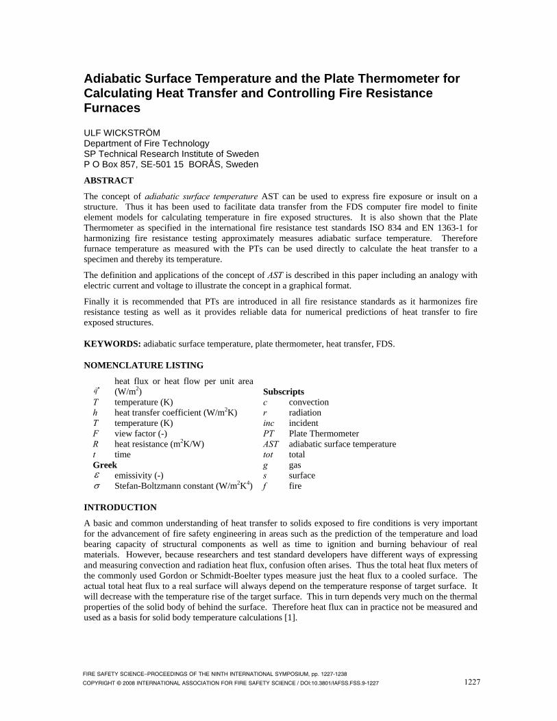
Alternatively the total heat transfer may be expressed in terms of one single temperature, i.e. the adiabatic surface temperature. This temperature is defined as the temperature a surface would get if it absorbs no heat. In an electrical analogy it is the potential of a point between the potentials corresponding to the radiation temperature and the gas temperature as visualized in Fig. 2.
)() ( 44tot sASTcsAST TThTTq −+−=′′ εσ (13)
Tr Tg
Rc cr qq ′′+′′ Rr
Ts Ts
1230
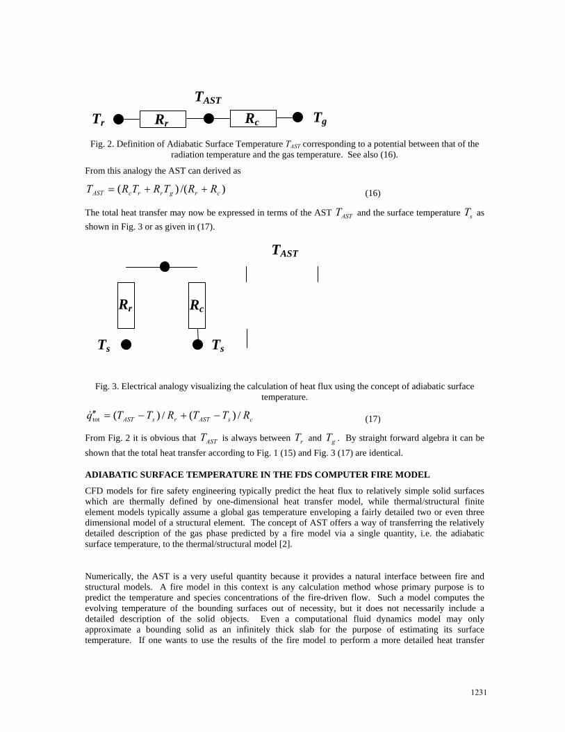
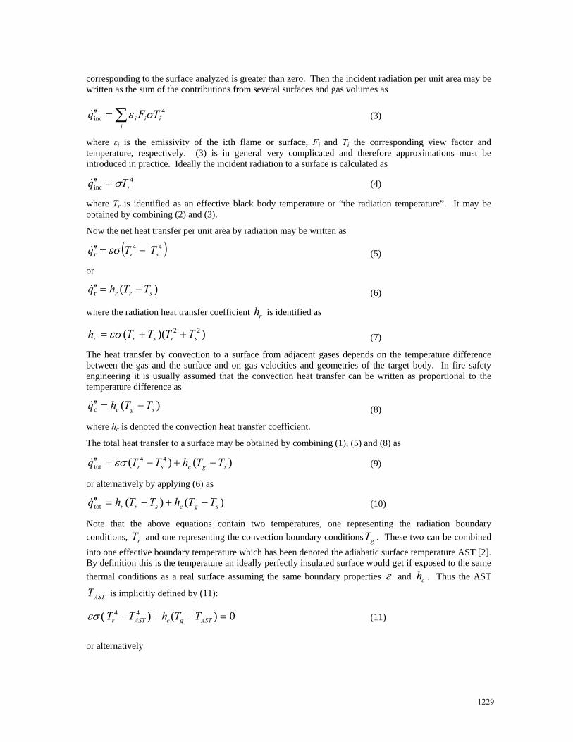
Fig. 2. Definition of Adiabatic Surface Temperature TAST corresponding to a potential between that of the radiation temperature and the gas temperature. See also (16).
From this analogy the AST can derived as
)/()( crgrrcAST RRTRTRT ++= (16)
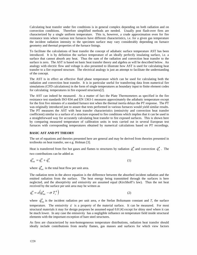
The total heat transfer may now be expressed in terms of the AST ASTT and the surface temperature sT as shown in Fig. 3 or as given in (17).
Fig. 3. Electrical analogy visualizing the calculation of heat flux using the concept of adiabatic surface temperature.
csASTrsAST RTTRTTq /)(/)(tot −+−=′′ (17)
From Fig. 2 it is obvious that ASTT is always between rT and gT . By straight forward algebra it can be shown that the total heat transfer according to Fig. 1 (15) and Fig. 3 (17) are identical.
ADIABATIC SURFACE TEMPERATURE IN THE FDS COMPUTER FIRE MODEL
CFD models for fire safety engineering typically predict the heat flux to relatively simple solid surfaces which are thermally defined by one-dimensional heat transfer model, while thermal/structural finite element models typically assume a global gas temperature enveloping a fairly detailed two or even three dimensional model of a structural element. The concept of AST offers a way of transferring the relatively detailed description of the gas phase predicted by a fire model via a single quantity, i.e. the adiabatic surface temperature, to the thermal/structural model [2].
Numerically, the AST is a very useful quantity because it provides a natural interface between fire and structural models. A fire model in this context is any calculation method whose primary purpose is to predict the temperature and species concentrations of the fire-driven flow. Such a model computes the evolving temperature of the bounding surfaces out of necessity, but it does not necessarily include a detailed description of the solid objects. Even a computational fluid dynamics model may only approximate a bounding solid as an infinitely thick slab for the purpose of estimating its surface temperature. If one wants to use the results of the fire model to perform a more detailed heat transfer
Rc Rr
Ts Ts
Tr
TAST
Tg RcRr
TAST
1231

calculation within the solid, then some sort of interface is required to transfer information at the gas-solid interface.
To test the idea of using the adiabatic surface temperature as an interface between a fire and structural model, a series of compartment fire experiments performed at NIST was modelled using Version 5 of the CFD model Fire Dynamics Simulator (FDS)5 and the commercial finite-element program ANSYS6. , which were then input into ANSYS following the procedure defined above. There is nothing within FDS or ANSYS that was deliberately set to facilitate the exchange of information. FDS simply used a 10 cm uniform mesh, and all solid obstructions were forced to conform to this mesh. ANSYS used a finite element mesh that conformed exactly to the shapes of the structural components. A simple interpolation scheme was worked out to translate uniformly spaced values of the adiabatic surface temperature calculated by FDS into boundary conditions appropriate for the solid phase heat transfer calculation performed by ANSYS.
Actually adiabatic surface temperatures can be calculated and obtained from version 5 of the NIST Fire Dynamic Simulator (FDS) [7]. FDS then computes the gas phase temperatures and heat fluxes to structural steel components, and produces as output a file of temporally and spatially varying values of the adiabatic surface temperature[2]. These temperatures may then be used directly as input to e.g. finite element computer codes for calculating temperature in fire exposed structures. The transfer of boundary condition data from the CFD calculations is in general very complex as it must consider contributions by radiation from several surfaces and smoke layers with various temperatures and by convection from adjacent gases. All these compounds can be included in the AST. Thus the heat transfer in the finite element calculation stage is thoroughly simplified. The heat transfer can be calculated as shown by (13).
Fig. 4 shows results from a combined FDS and finite element calculation for a truss coated with a specified insulation thickness of 19 mm (for details see [2] and [8]). The web of the truss consisted of circular steel bars, 25 mm in diameter. The steel temperature was calculated in two ways for comparison, firstly by just using the FDS code and its internal algorithm for calculating boundary temperatures and secondly by using the AST obtained from FDS as the only boundary condition for a separate finite element calculation. Note the good agreement between the temperatures obtained directly with FDS code and the corresponding temperature calculated with the finite element code ANSYS [9]. The third upper curve in Fig. 4 shows measured temperatures from experiments giving an indication on how the FDS code can predict the fire development. The small discrepancy between the two theoretical curves in Fig. 4 may be explained by the fact that FDS curve is obtained by a one-dimensional analysis and the ANSYS curve by a two-dimensional analysis.
Truss A Web Steel Temperature
Time (min)
0 15 30 45 60 75 90
Tem
pera
ture
(°C
)
0
100
200
300
400
500
600
700
800
ExperimentFDSANSYS
Fig. 4. Steel temperatures predicted and measured at a location on a truss from the investigation of the World Trade Center collapse [2]. The predictions were made for comparison of steel temperatures computed directly with FDS and alternatively with ANSYS using AST as the only boundary input.
1232
ADIABATIC SURFACE TEMPERATURE AND THE PLATE THERMOMETER
The Plate Thermometer according to ISO 834 and EN 1363-1
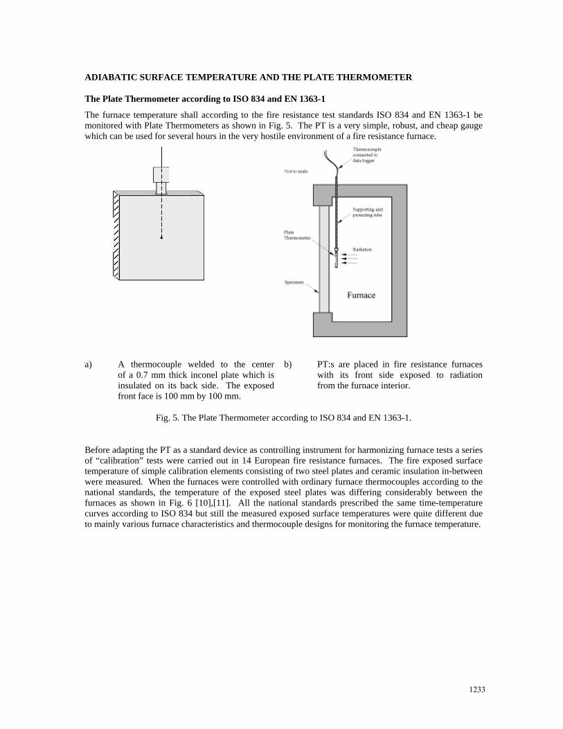
The furnace temperature shall according to the fire resistance test standards ISO 834 and EN 1363-1 be monitored with Plate Thermometers as shown in Fig. 5. The PT is a very simple, robust, and cheap gauge which can be used for several hours in the very hostile environment of a fire resistance furnace.
a) A thermocouple welded to the center of a 0.7 mm thick inconel plate which is insulated on its back side. The exposed front face is 100 mm by 100 mm.
b) PT:s are placed in fire resistance furnaces with its front side exposed to radiation from the furnace interior.
Fig. 5. The Plate Thermometer according to ISO 834 and EN 1363-1.
Before adapting the PT as a standard device as controlling instrument for harmonizing furnace tests a series of “calibration” tests were carried out in 14 European fire resistance furnaces. The fire exposed surface temperature of simple calibration elements consisting of two steel plates and ceramic insulation in-between were measured. When the furnaces were controlled with ordinary furnace thermocouples according to the national standards, the temperature of the exposed steel plates was differing considerably between the furnaces as shown in Fig. 6 [10],[11]. All the national standards prescribed the same time-temperature curves according to ISO 834 but still the measured exposed surface temperatures were quite different due to mainly various furnace characteristics and thermocouple designs for monitoring the furnace temperature.
1233
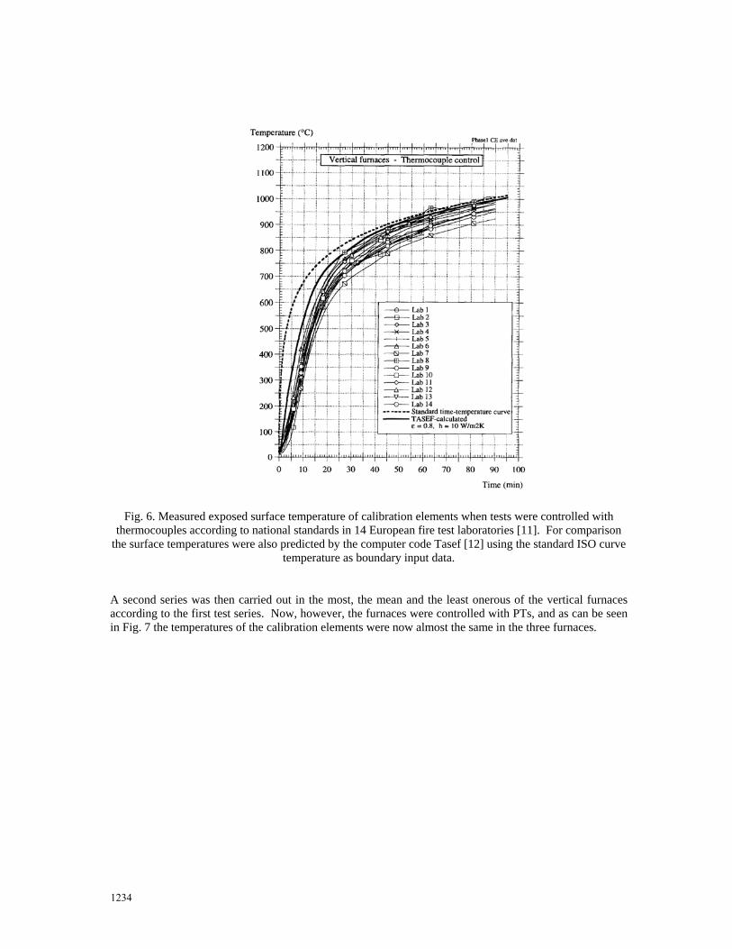
Fig. 6. Measured exposed surface temperature of calibration elements when tests were controlled with thermocouples according to national standards in 14 European fire test laboratories [11]. For comparison
the surface temperatures were also predicted by the computer code Tasef [12] using the standard ISO curve temperature as boundary input data.
A second series was then carried out in the most, the mean and the least onerous of the vertical furnaces according to the first test series. Now, however, the furnaces were controlled with PTs, and as can be seen in Fig. 7 the temperatures of the calibration elements were now almost the same in the three furnaces.
1234

Fig. 7. Measured exposed surface temperature of the calibration element when the furnaces were controlled using PTs [11]. The surface temperatures are also predicted by the computer code Tasef [12] using the PT
temperatures, i.e. in this case the standard ISO fire curve, as boundary input data.
The calibration element temperature was also successfully predicted with the finite element computer code Tasef [12] using the standard time-temperature curve, i.e. the target curve for the PT readings, as boundary input conditions. Then it was assumed that the PT actually measures the AST as outlined in the section below.
The PT can measure AST
The PT exchanges heat by radiation and convection as any fire exposed surface:
where the index PT refers to the Plate Thermometer.
A heat balance equation can now be established for the PT. Thus the heat flux according to (18) equals the transient heat for raising the temperature of the inconel plate of the PT.
Fig. 8 shows the calculated response of the PT, when exposed to a uniform furnace temperature fT according to the ISO 834 standard time-temperature curve. It was then assumed that the heat transfer to the PT is calculated according to (18) assuming that fgr TTT == and that the plate has a uniform
)() ( 44PTtot, PTgPTPTrPT TThTTq −+−=′′ σε (18)
1235

temperature (lumped heat). The emissivity PTε and the convection heat transfer coefficient PTh are assumed equal 0.9 and 25 W/(m2 K), respectively.
0
200
400
600
800
1000
0 10 20 30 40 50 60
Time [min]
Tem
pera
ture
[ºC
]
Plate thermometer
ISO 834
Fig. 8. Calculated response of a PT when exposed standard fire test conditions according to ISO 834.
Note that the PT temperature follows the nominal temperature curve very closely except for the first few minutes. Thus the time delay of the PT temperature recordings due to its inertia in a standard fire test may be neglected (except for the first four to five minutes). The inconel plate of the PT is thin and the heat lost on its back side is negligible. Thus the net heat transferred to the surface is small and can be neglected, which implies that the PT actually measures the AST for a given surface emissivity PTε and a given
convection heat transfer coefficient PTh . As negligible heat is absorbed by the PT, its heat balance equation can be written as
0)()( 44 =−+− PTgPTPTrPT TThTTσε (19)
An approximate alternative expression of the net heat transfer totq ′′ to a specimen surface with an
emissivity ε and a convection heat transfer coefficient ch can now be obtained in terms of the PT temperature from (13) as:
)()( 44sPTcsPTtot TThTTq −+−=′′ εσ (20)
where the AST has been replaced by the PT temperature.
The heat transfer according (20) was used when calculating the calibration element temperature shown in Fig. 7. As you can see the match between calculated and measured temperatures in the three furnaces is excellent. Some of the small deviations that can be observed in Fig. 7 can even be accounted for by the fact that the nominal time-temperature curve has been used as input for calculating the temperature. The actual furnace temperatures measured with the PTs are slightly different as the furnace operators were of course not fully able to perfectly follow the target standard curve.
Error analysis discussion
As the PT and specimen surfaces in general have different heat transfer properties (emissivities and convection heat transfer coefficients) an error q ′′Δ is introduced when applying (20). The magnitude of
1236
this error is obtained by subtracting (9) from (20) and then by adding (19). The following expression is then obtained:
))(()()( 44PTgPTsPTrPTs TThhTTq −−+−−=′′Δ σεε (21)
Thus the error is small when the surface emissivities as well as the convective heat transfer coefficients of the PT and the specimen are nearly the same. Therefore the surfaces of the PTs are blasted and heat treated before being used to get an emissivity similar to most building material (about 0.8). The PT has also a relatively large surface, 100 mm by 100 mm, to obtain a convection heat transfer coefficient similar to a specimen. As PTT always has a value between rT and gT the error vanishes when these two temperatures are close. The equation above (21) indicates also implicitly that ordinary small thermocouples with much higher convection heat transfer coefficients than most test specimen surfaces (could be an order of magnitude) yield temperatures that are not suitable to be used directly for calculations of heat flux to fire exposed structures.
In practice the internal temperatures of a structural element is in most fire resistance cases not very sensitive to the heat transfer conditions. However, the fire or the furnace temperatures are in general not a well defined quantities. They depend very much on how they are measured when the gas temperature and the radiation temperatures are not equal. A small bead thermocouple will monitor a temperature close to the actual gas temperature while the bigger standard PT will monitor a temperature close to the radiation temperature. But as the convection heat transfer coefficient and the emissivity of a PT in general is of the same magnitude as that of a structural element surface, the PT measurements yield suitable adiabatic temperatures to be used in (13.
Calculation of incident radiation
The plate thermometer measures temperature. Based on that temperature the incident radiation level may under certain conditions, like a standard fire resistance furnace test, be accurately estimated. Thus given PT the yields the adiabatic surface temperature, the incident radiation heat flux incq ′′ may be obtained from (4) and (11) as
PTPTgPTPT TThTq εσ /)(4inc −−=′′ (22)
The latter term in (22), i.e. PTPTgPT TTh ε/)( − , is relatively small and may be treated as an error term.
For example with εPT = 0.8, hPT = 25 W/m2 K, )( PTg TT − =50 K and a temperature level of 1 000 K the latter term of (22) is less than 3%. At higher temperature levels and at minor deviations between gas and radiation temperatures this error is much smaller and probably seldom greater than must be anticipated when measuring incident radiation directly with e.g. water cooled heat flux meters or any slug calorimeter as being discussed to be introduced in the American furnace test standard ASTM E119 [13,14]. For the first few minutes when the inertia of the PT has an influence, the PT may of course also be treated as a slug calorimeter and the incident heat flux may be obtained by an inverse analysis in a similar way as for the Differential Flame Thermometers (also named Double Plate Thermometer [14]).
It has been demonstrated in a paper by Ingason and Wickström [15] that the PT as described in the fire resistance test standards ISO 834-1 and EN 1363-1 can also be used for measuring incident radiant flux even under ambient gas temperature conditions as an alternative to water cooled total flux heat meters (HFMs). Measurements with a PT mounted in the cone calorimeter and exposed to different heat flux levels were analysed, and simultaneous measurements with total HFMs and PTs were performed in large scale tests. The incident radiant flux to a target was derived from measurements with total HFMs and PTs, respectively. The measurements with the two methods matched well, and it was therefore concluded that the PT is a practical alternative for monitoring thermal conditions including incident radiant heat flux particularly under field conditions.
1237
SUMMARY AND CONCLUSIONS
In this paper it has been shown how the concept of AST can be used to express fire exposure or insult on a structure. The concept has been used to facilitate data transfer from the FDS fire computer model to finite element models for calculating temperature in fire exposed structures. It is also shown that PTs as specified in the international fire resistance test standards ISO 834 and EN 1363-1 approximately measure adiabatic temperature. Thus the furnace temperatures as measured with the PTs can in a straightforward simple way be used to calculate the heat transfer to a specimen surface.
It is the strong conviction of the author that the PT is the most suitable instrument for monitoring temperature and controlling fire resistance furnaces. It harmonizes testing and it provides reliable data for numerical calculations. No alternative instruments or gauges are as simple to use, robust, accurate, and cheap. It is therefore strongly recommended to be specified in all fire resistance test standards.
REFERENCES
[1] Wickström, U.and Wetterlund I., Total heat flux cannot be measured, Interflam 2004, pp 269
[2] Wickström, U., Duthinh, D. and McGrattan, K., Adiabatic Surface Temperature for Calculating Heat Transfer to Fires Exposed Structures, Interflam 2007, London, England, September 3-5, 2007, pp. 943.
[3] Holman, , J.P., Heat Transfer, 4th ed., McGraw Hill, 1976
[4] EN 1991-1-2, Eurocode 1: Actions on structures – Part 1-2: General actions – Actions on structures exposed to fire
[5] McGrattan, K.B., S. Hostikka, J.E. Floyd, H.R. Baum and R.G. Rehm, Fire Dynamics Simulator (Version 5), Technical Reference Guide, NIST SP 1018-5, National Institute of Standards and Technology, Gaithersburg, Maryland, July 2005
[6] ANSYS Inc., 275 Technology Drive, Canonsburg, Pennsylvania (http://www.ansys.com) [7] McGrattan, K.B., S. Hostikka, J.E. Floyd, H.R. Baum and R.G. Rehm, Fire Dynamics Simulator
(Version 5), Technical Reference Guide, NIST SP 1018-5, National Institute of Standards and Technology, Gaithersburg, Maryland, July 2005, section 12.3.7
[8] Gann, R. et al., Reconstruction of the Fires in the World Trade Center Towers, Federal Building and Fire Safety Investigation of the World Trade Center Disaster, NIST NCSTAR 1-5, National
[9] ANSYS Inc., 275 Technology Drive, Canonsburg, Pennsylvania
[10] Van de Leur, P.H.E. and Twilt, L., Fire Resistance Furnace Calibration. TNO-Report 96-CVB-R1323, 1996.
[11] Wickström, U. and Hermodsson, T., Comments on Paper by Kay, Kirby and Preston ‘Calculation of the Heating Rate of an Unprotected Steel Member in a Standard Fire Resistance Test’, Fire Safety Journal 29 (1997) 337-343, doi:10.1016/S0379-7112(97)00034-9.
[12] Sterner, E. and Wickström, U., TASEF - Temperature Analysis of Structures Exposed to Fire, SP Report 1990:05, Swedish National Testing and Research Institute, Borås, 1990.
[13] Sultan, M.A., A comparison of heat exposure in fire resistance test furnaces controlled by plate thermometers and by shielded thermocouples, Interflam 2004, Edinburgh, Scotland, July 5-7, 2004, pp. 219-229.
[14] Keltner, Ned R. and Jansens, Marc, Private communication.
[15] Haukur Ingason and Ulf Wickström, “Measuring incident radiant heat flux using the plate thermometer”, Fire Safety Journal, Volume 42, Issue 2, March 2007, Pages 161-166.
1238