ADIABATIC SHEAR BANDING IN DYNAMIC PLANE STRAIN ...rbatra/pdfpapers/plasticity1990(231-246).pdf ·...
16
International Journal of Plasticity, Vol. 6, pp. 231-246, 1990 0749-6419/90 $3.00 + .00 Printed in the U.S.A. Copyright © 1990Pergamon Pressplc ADIABATIC SHEAR BANDING IN DYNAMIC PLANE STRAIN COMPRESSION OF A VISCOPLASTIC MATERIAL R.C. BATRA and DE-SHIN Ltu University of Missouri-Rolla Abstract-- Dynamic plane strain thermomechanical deformations of a thermally softening vis- coplastic body subjected to compressive loads on the top and bottom faces are studied with the objective of exploring the effect of (a) modeling the material inhomogeneity by introduc- ing a temperature perturbation or assuming the existence of a weak material within the block, (b) introducing two defects symmetrically placed on the vertical axis of the block. The effect of setting the thermal conductivity equal to zero is also studied in the latter case. It is found that, irrespective of the way the material inhomogeneity is modeled, a shear band initiates from the site of the defect and propagates in the direction of maximum shearing stress. The value of the average strain at the instant of the initiation of the band depends upon the strength of the material defect introduced. Once the shear band reaches the boundaries of the block it is reflected back, the angle of reflection being nearly equal to the angle of incidence. 1. INTRODUCTION Adiabatic shear banding refers to the localization of the deformation into thin narrow bands of intense plastic deformation that usually form during high-rate plastic defor- mation. These bands often precede shear fractures. The experimental work in this area is due to ZENER and HOI.I.OMON [1944], COSXI~ et ai. [1980], Moss [1981], LINDHOI.M and JOHNSON[1983], HAR~EY, DLrFF¢ and HAW~.EY[1987], and M,~RCR~qD and DUFl~ [1988]. HARTI.EY et al. [1987], and MARCR,M~D and Du~Y [1988], have given a detailed history of the temperature and strain fields within a band formed in a thin steel tube deformed in simple torsion. During the last ten years, there have been numerous studies aimed at analyzing the initiation and growth of shear bands in the one-dimensional simple shearing problem. For example, CLWrON [1980] and B~ [1981] analyzed the growth of infinitesimal peri- odic perturbations superimposed on a body deformed by a finite amount in simple shear. BURNS [1985] used a dual asymptotic expansion to account for the time depen- dence of the homogeneous solution in the analysis of the growth of superimposed pe- riodic perturbations. Other works include those of MEgZER [1983], WU and FREUND [1984], CLrFTON et al. [1984], COLEMA~ and HODGDON [1985], WRIGHT and B^TL~ [1985], WgmRT and WALTER [1987], BATg,J, [1987a,1987b], Znm and An:~TIs [1988], and BATgXand IOM [1990]. We note that ROGERS[1979,1983] and T~Moxmc [1987] have reviewed various aspects of shear banding, and AN,~gD et al. [1988] have generalized one-dimensional stability analysis of CLmrON [1980] tO three-dimensional problems. Recently LEMONDSand NEEDI~MAJ~r [1986a,1986b], AN,~rD et al. [1988], NEEDLE- MAN [1989], BATgA and Ln~ [1989], and Sm.rrrLE and SMIXR [1988] have studied the initiation and growth of shear bands in plane strain deformations of a softening mate- rial. Except for Needleman, and Batra and Liu, these works neglected the effect of inertia forces. Batra and Liu studied the coupled thermomechanical deformations of a thermally softening viscoplastic solid and modeled the material inhomogeneity by 231
Transcript of ADIABATIC SHEAR BANDING IN DYNAMIC PLANE STRAIN ...rbatra/pdfpapers/plasticity1990(231-246).pdf ·...

International Journal o f Plasticity, Vol. 6, pp. 231-246, 1990 0749-6419/90 $3.00 + .00 Printed in the U.S.A. Copyright © 1990 Pergamon Press plc
A D I A B A T I C S H E A R B A N D I N G IN D Y N A M I C P L A N E S T R A I N C O M P R E S S I O N O F A V I S C O P L A S T I C M A T E R I A L
R.C. BATRA and DE-SHIN Ltu
University of Missouri-Rolla
Abstract-- Dynamic plane strain thermomechanical deformations of a thermally softening vis- coplastic body subjected to compressive loads on the top and bottom faces are studied with the objective of exploring the effect of (a) modeling the material inhomogeneity by introduc- ing a temperature perturbation or assuming the existence of a weak material within the block, (b) introducing two defects symmetrically placed on the vertical axis of the block. The effect of setting the thermal conductivity equal to zero is also studied in the latter case. It is found that, irrespective of the way the material inhomogeneity is modeled, a shear band initiates from the site of the defect and propagates in the direction of maximum shearing stress. The value of the average strain at the instant of the initiation of the band depends upon the strength of the material defect introduced. Once the shear band reaches the boundaries of the block it is reflected back, the angle of reflection being nearly equal to the angle of incidence.
1. INTRODUCTION
Adiabatic shear banding refers to the localization of the deformation into thin narrow bands of intense plastic deformation that usually form during high-rate plastic defor- mation. These bands often precede shear fractures. The experimental work in this area is due to ZENER and HOI.I.OMON [1944], COSXI~ et ai. [1980], Moss [1981], LINDHOI.M and JOHNSON [1983], HAR~EY, DLrFF¢ and HAW~.EY [1987], and M,~RCR~qD and DUFl~ [1988]. HARTI.EY et al. [1987], and MARCR,M~D and Du~Y [1988], have given a detailed history of the temperature and strain fields within a band formed in a thin steel tube deformed in simple torsion.
During the last ten years, there have been numerous studies aimed at analyzing the initiation and growth of shear bands in the one-dimensional simple shearing problem. For example, CLWrON [1980] and B~ [1981] analyzed the growth of infinitesimal peri- odic perturbations superimposed on a body deformed by a finite amount in simple shear. BURNS [1985] used a dual asymptotic expansion to account for the time depen- dence of the homogeneous solution in the analysis of the growth of superimposed pe- riodic perturbations. Other works include those of MEgZER [1983], WU and FREUND [1984], CLrFTON et al. [1984], COLEMA~ and HODGDON [1985], WRIGHT and B^TL~ [1985], WgmRT and WALTER [1987], BATg,J, [1987a,1987b], Znm and An:~TIs [1988], and BATgX and IOM [1990]. We note that ROGERS [1979,1983] and T~Moxmc [1987] have reviewed various aspects of shear banding, and AN,~gD et al. [1988] have generalized one-dimensional stability analysis of CLmrON [1980] tO three-dimensional problems.
Recently LEMONDS and NEEDI~MAJ~r [1986a,1986b], AN,~rD et al. [1988], NEEDLE- MAN [1989], BATgA and Ln~ [1989], and Sm.rrrLE and SMIXR [1988] have studied the initiation and growth of shear bands in plane strain deformations of a softening mate- rial. Except for Needleman, and Batra and Liu, these works neglected the effect of inertia forces. Batra and Liu studied the coupled thermomechanical deformations of a thermally softening viscoplastic solid and modeled the material inhomogeneity by
231
232 R . C . BATRA and D-S. D u
introducing a temperature bump at the center of the block whose boundaries were taken to be perfectly insulated. Two different loadings, namely, those corresponding to sim- ple shearing and simple compression of the block, were considered. Here, we examine the effect of (a) modeling the material inhomogeneity in two different ways, namely, introducing a temperature perturbation and assuming the existence of a weak mate- rial, (b) introducing two defects placed symmetrically on the vertical axis of the block, (c) varying the reduction in the flow stress of the weak material, and (d) two different sets of initial conditions.
11. F O R M U L A T I O N OF THE PROBLEM
We use an updated Lagrangian description (e.g., see BATHE [1982]) to analyze the plane strain thermomechanical deformations of the viscoplastic body. That is, in or- der to solve for the deformations of the body at time (t + At) , the configuration at time t is taken as the reference configuration. However, it is not assumed that the defor- mations of the body from time t to time (t + ,at) are infinitesimal. With respect to a fixed set of rectangular Cartesian coordinate axes, we denote the position of a mate- rial particle in the configuration at time t by X,, and in the configuration at time (t + ,at) by x~. In terms of the referential description the governing equations are
(p J)" = 0, (2.1)
poV~ = T~,~, (2.2)
pop = -Q~ .~ + T,-~v~,,. (2.3)
supplemented by appropriate constitutive relations, and initial and boundary condi- tions. Equations (2.1), (2.2), and (2.3) express, respectively, the balance of mass, the balance of linear momentum, and the balance of internal energy. Here p is the mass density of a material particle in the current configuration at time t + At , Po its mass density in the reference configuration; a superimposed dot indicates a material time derivative; J = po/p equals the determinant of the deformation gradient F,~ -~ xi.,~; vi is the velocity of a material particle in the xrdirection, T~ is the first Piola-Kirchoff stress tensor; a comma followed by oe(i) implies partial differentiation with respect to X~(xi); a repeated index signifies summation over the range of the index; e is the internal energy per unit mass; and Q~ is the heat flux. We assume that plane strain deformations occur in the X~ - X2 plane, so that x3 = X3 and the indices i and oL range over 1,2.
We note that even when the applied overall strain-rate is kept fixed, different mate- rial particles undergo deformations at varying strain-rates. During the course of a loading process in which a shear band forms, the temperature of a material particle may also increase considerably. A constitutive relation that can model the material response over changes in plastic strain-rate and temperature of several orders of magnitude is needed to properly analyze the shear band problem. HARTLEY et al. [1987], and M A R C ~ D and D t ~ r t [1988], have proposed a power law that seems to describe adequately the simple shearing deformations of the steels tested. However, a constitutive relation ap- plicable to more general deformations is not readily available in the open literature.

Adiabatic shear banding 233
Here we assume that the following constitutive relations describe adequately the mate- rial response:
a e = --p(p)5ij + 2I~D~j,
Ti,~ = ( po /p )X~ , , j o i j , (2.4)
2# = [ O o / ( , ' 3 1 ) ] (1 -- J,O)(l + bl) m,
2Di j = vi.j + uj.i, (2.5)
2 /2 = [)ijC)j,, D v = D~j - (1 /3)DkkSi . i , (2.6)
p ( p ) = B ( p / p r - - 1), (2.7)
Q,, = - k ( p o / p ) X , , . i O , i , (2.8)
Poe = poCO + p o p p ( p ) / p 2. (2.9)
Here, ai.i is the Cauchy stress tensor, ao is the yield stress in a quasi-static simple ten- sion or compression test, v is the coefficient of thermal softening,/Sij is the deviatoric strain-rate tensor, Di2 is the strain-rate tensor, 6 0 is the Kronecker delta, B may be interpreted as the bulk modulus, Pr is the mass density in the stress free reference con- figurations, c is the specific heat, k is the thermal conductivity, and parameters b and m describe the strain-rate sensitivity of the material. The material parameters b, m, B, k, and c are taken to be independent of the temperature. Equation (2.8) is the Fou- rier law of heat conduction, and eqn (2.4)1 may be interpreted as a constitutive rela- tion for a non-Newtonian fluid whose viscosity t~ depends upon the temperature and the strain-rate. Alternatively, defining s u by
s V = o V + [ p -- ( 2 / 3 ) / ~ D k , ] 6 i j (2.10)
= 2/~bij, (2.11)
we can write eqns (2.4) and (2.5) as
[ (1 /2 ) (s~ js j , ) ] ' /2 = [oo /x ,~ ] (1 -- =,0)(1 + b / ) m (2.12)
which can be viewed as a generalized von Mises yield surface when the flow stress (given by the right-hand side of (2.12)) at a material panicle depends upon its straLmrate and temperature. That the flow stress decreases linearly with the temperature rise has been observed by BEu. [1968], Ltl, rOnOtM and Jo~so lq [1983], and Ln~ and W^c_,o~R [1986]. The range of temperatures examined by these investigators is not as large as that ex- pected to occur in the shear band problem. However, constitutive relations akin to eqn (2.4) have been used by Zmlqicmwicz et al. [1981] for analyzing the extrusion prob- lem, by BATRA [1988] in studying the steady-state penetration of a viscoplastic target by a rigid cylindrical penetrator, and by BATRA and L ~ [1989] for studying the shear band problem.

234 R.C. BATRA and D-S. Liu
In terms of the nondimensional variables
# = aloo, p = p / % , g = s / % , ~ = V/Vo,
i = tvo/H, T = T /%,
£ = x / H , 0 = 0 / 0 o , b = b ( v o / H ) , ~ = ~0o,
= P/Pr, P "~ Po/Pr, X = X / H ,
(2.13)
m arl)2o/(7o, ~ = k/(PrCVoH),
Oo = a o / ( a r c ) , B = B/ao,
the governing equations can be written as
+ av~,i = O, (2.14)
6at)i = T, . . . . (2.15)
PO ----" ~O,ii -{- (P/Pr) [ 1 / ( x / 3 l ) ] (1 + b t ) m ( l - vO)ff)Off)O, (2.16)
o o = - B ( p - 1)~ o + [ l / x / 3 I ) ] (1 + b I ) " ( 1 - ~O)D o, (2.17)
where we have dropped the superimposed bars. In eqns (2.13) 2H is the height of the block and vo the imposed velocity on the top and bottom surfaces. In eqns (2.14)- (2.16) all of the differentiations are with respect to nondimensional variables. We note that in eqn (2.16) all, rather than 90-95% as stated by TAYLOR and QtrISSEY [1934], of the plastic working is assumed to be converted into heat.
For the viscoplastic block being deformed in simple compression we study only those deformations that remain symmetric about the horizontal and vertical planes passing through the center of the block. Thus we analyze the deformations of the material in the first quadrant. With the origin of the coordinate axes situated at the center of the undeformed block (cf. Fig. 1), we can write the pertinent boundary conditions as follows
z['- t xz, . . . . . . . . . . . . . . . . . . . . .
u
zH : o
i
, . . . . . . . . . . . . . . . . . . . . . . . . . . * ~ r
2U
w X |
1 . 0 " E ~ 0.8-
0 . 5
$0.4 T R 0.2 E0.0 S $ . . . . i . . . . i . . . . i . . . . i
2 4 5
100 * A V G . ~ T R A I N
( b )
Fig. 1. (a) The problem studied, (b) Stress-strain curve in simple compression for the material studied.
Adiabatic shear banding 235
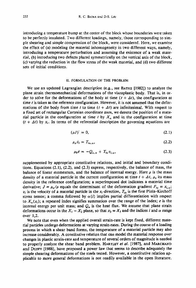
vl = O, T 2 t = 0 , Qt = O at xt = X l = O,
U 2 = 0 , TI2 ~- 0, Q 2 = O a t x 2 = X 2 = O ,
Ti~N~ = O, Q~N~ = 0 on the right face, (2.18)
v2 = - U ( t ) , T~2 = 0, Q2 = 0 on the top surface.
That is, boundary conditions resulting f rom the assumed symmetry of deformations are applied to the left and bo t tom faces, the right face of the block is taken to be trac- tion free, and a prescribed normal velocity and zero tangential tractions are applied on the top face. Note that the initially flat top surface is assumed to stay flat through- out the deformations of the block. All four sides of the block are assumed to be per- fectly insulated.
We consider two different sets of initial conditions. First we take
p(X,O) = 1.0, vt(X,O) = O, vz(X,O) = O, O(X,O) = O, (2.19)
and model a material inhomogenei ty/ f law by assuming that
t~ = [1 - ¢(1 - r2 )9exp( -5 r2 ) ] 1[(1 + bl)m/(x /3I )] (1 - ~0)1 (2.20)
r 2 = ( X I - Xl° ) 2 + (X2 - X ° ) 2. (2:21)
That is, the material around the point X ° is weaker than the surrounding material. In this case we took
U ( t ) = t/0.005, 0 < t -< 0.005 (2.22)
= I t -_- 0.005.
Another set of initial conditions studied involved perturbing the steady state solution corresponding to
vl = 0.37xl, v2 = - x 2 (2.23)
for an average applied strain-rate of 5,000 sec - I by superposing on it a temperature perturbat ion given by
AO = ~(1 - r 2 ) 9 e x p ( - 5 r 2 ) . (2.24)
The velocity field (2.23) and the temperature distribution (2.24) were taken as the ini- tial conditions, and U ( t ) was set equal to 1.0 for t _ 0. We note that the value of
in eqns (2.20) and (2.24) models, in some sense, the strength of the defect. We refer the reader to B A T ~ and L ~ [1989] for details of seeking an approximate
solution of the problem numerically.
236 R . C . RATRA and D-S. LIu
IIl. C O M P U T A T I O N AND DISCUSSION OF RESULTS
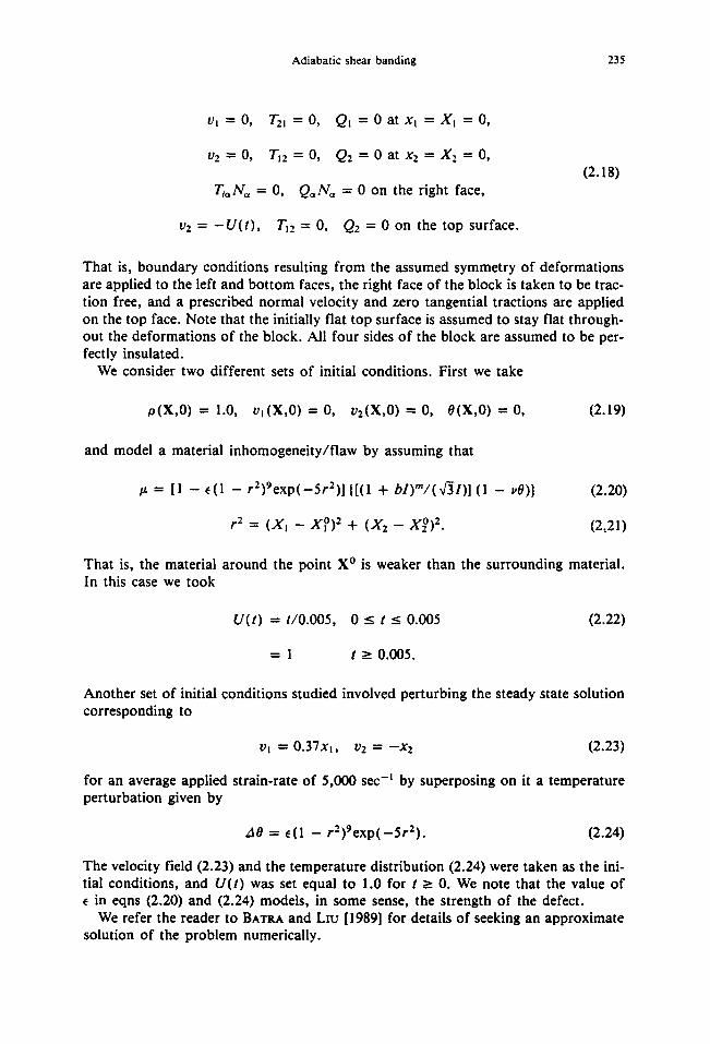
In order to compute numerical results we assigned following values to various mate- rial and geometric parameters.
b = 10,000 sec, v = 0.0222°C - l , oo = 333 MPa,
k = 4 9 . 2 2 W m -l °C- t , c = 4 7 3 J k g -I °C - l ,
Po = 7,800 kg m -3, B = 128 GPa, H = 5 mm, (3.1)
Vo = 2 5 m sec - l , m =0 .025 .
Except for the value of the thermal softening coefficient u, these values are for a typical hard steel. We assigned a rather large value to ~, to reduce the CPU time required to solve the problem. For the values given in (3. I), 0o = 89.6°C, the nondimensional melt- ing temperature equals 0.5027, and the average applied strain-rate equals 5,000 sec -I . Figure Ib depicts the effective stress se, defined as the left-hand side of eqn (2.12), versus the average strain. The presumed high value of the thermal softening coeffi- cient results in material softening due to the heating of the material overcoming the material hardening due to strain-rate effects right from the beginning.
III. 1. Results with initial temperature perturbation
Figure 2a depicts the isotherms for the initial temperature distribution (2.24) with e = 0.2 centered around the point (0.0, 0.375). In this case the initial velocity field is assumed to be given by (2.23) and U(t) = 1.0 for t _> 0. The peak temperature 0ma x
of 0.2 occurs at the center of perturbation. The isotherms look elliptical because of the different scales along the horizontal and vertical axes. Since the boundaries of the block are taken to be perfectly insulated the heat generated due to plastic working raises the temperature of every material point. The isotherms at five different values of the average strain are plotted in Figs. 2b through 2e. These suggest that material points along lines passing through the center of perturbation and inclined at ___45 ° with the horizontal axis are heated more than other particles. Also contours of successively higher temperatures seem to originate from (0.0, 0.375) and propagate in the direction of max- imum shearing stress. They get arrested temporarily at the boundaries of the block and when the material at the boundary where these contours meet it gets heated up, these start propagating into the material as if the incident contours were reflected back into the body, the angle of reflection being almost equal to the angle of incidence. This phenomenon becomes more evident from the plots in Fig. 3 of the contours of the second invariant I of the deviatoric strain-rate tensor. In Figs. 3a through 3f the contours of I are plotted at successively higher values of the average strain "tavg. In each case the peak value/max of I occurs at the point (0.0, 0.375) where the tempera- ture is maximum. At an average strain of 0.04,/max = 11.44 implying thereby that the material surrounding it is deforming at a strain-rate greater than 50,000 sec -~. For 3'avs = 0.04, 0rex = 0.341 occurs at (0.0, 0.375) and equals 68.2% of the presumed melting temperature of the material. We note that when the temperature perturbation was introduced at (0.0, 0.0) (BATRA • Lrv [1989]),/max and 0max at 3'avg = 0.04 equalled 8.73 and 0.313, respectively. For the problem being currently analyzed, the contours

Adiabatic shear banding 237
l .O0|
J ' 7 5 L
0 . 2 5 ~ . ~ I
0 . 0 0 I ~ . . . . , . . . . . ~ . . . . . , . . . . . 0 . 2 5 0 . 5 0 0 . 7 5 1 . 0 0
.oo! -- I 0.75~_________~
0,0 i i 0 . 2 5 ~ . ~
0 . 0 0 1 . . . . . v . ( ' ~ , . . . . . , . . . . .
0.25 0.50 0.75 1.00
(a) (b)
0 . 2 5 0 . 5 0 0 . 7 5 1 .00 0 . 2 5 0 . 5 0 0 . 7 5 l .O0
(c) (d)
X 2 l.o0 j ,-~ ~ .
0.5o
0 .25
o.oo,---o.~-';)-.~o o.~s ,.oo
(e)
Fig. 2. Isotherms plotted in the reference configuration at different values of the average strain when the mate- rial defect is modeled by introducing a temperature perturbation,
(a) ray8 = 0.0, 0ma~ = 0.2; __ 0.I0 ..... 0.125 ....... 0.150. (b) "l.vs = 0.03, 0max = 0.28; _ _ 0.10 . . . . . 0.15 . . . . . . . 0 .20 . . . . . 0 .25, (c) Yavg = 0.035, #max = 0.304; _ _ 0.10 . . . . . 0.15 . . . . . . . 0 .20 . . . . . 0 .25. (d) ")'ave = 0.0375, 0, , , , , , = 0.3213; _ _ O.10 . . . . . 0.15 . . . . . . . 0 .20 . . . . . 0.25 . . . . 0 .30. (e) "lave = 0.04, 0m~x = 0.341; _ _ 0.10 . . . . . 0.15 . . . . . . . 0 .20 . . . . . 0.25 . . . . 0 .30.
of I originate at (0.0, 0.375) and then fan out along the direction of maximum shear- ing. There appear to be sources of energy building up at (0.0, 0.375) and three other points on the boundary where the parallelogram through (0.0, 0.375) with adjacent sides making angles of ±45 ° with the horizontal axis intersect it. When there is suffi- cient energy built up at these points contours of successively higher values of I origi- nate from these points and propagate along the direction of maximum shearing stress. Also as the deformation of the block progresses, these contours become narrower im- plying thereby that severe deformations are localizing into thin bands.
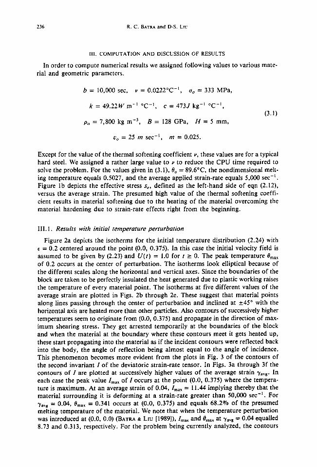
Figures 4a through 4c depict the velocity field in the Xt and X2 direction for "Yavg = 0.0, 0.035 and 0.040. The velocity field at "Yug = 0.0 is a graphical representa- tion of eqns (2.23) and corresponds to a homogeneous deformation of the block. Once the deformation localizes the velocity field within the material adjoining the sides of the parallelogram stated above varies sharply, and it varies almost linearly within the

238 R . C . BATRA and D-S. Ltu
t . oo ~ ~ . _ - e 7
0 . 0 o 0 . 0 0 0 . 2 5 0 . 5 0 0 . 7 5 1 .00
(a)
0 . 7 5 - ~ "@'~ - 0 . 7 5
?o2, ! o.oo 0 . 2 5 0 . 5 0 0 . 7 5 1 .00
(c)
1 .00 ....~ 1 . 0 0
o.,o o.,o I 0.25
o.oo I ~ ~ ( . . . . . , . . . . I o.oo 0 . 2 5 0 . 5 0 0 . 7 5 1 .00
1. O0
t )!0
, . . . . , . . . . . , . . . . . I
0 . 2 5 0 . 5 0 0 . 7 5 1 .00
(b)
! . . . . . I . . . . . ~ . . . . . I . . . . . I
0 . 2 5 0 . 5 0 0 . 7 5 1 .00
(d)
x 2
(e) (f)
Fig. 3. Contours of the second invariant I of the deviatoric strain-rate tensor at different values of the average s t ra in when the mater ia l defect is mode l e d by a t e m p e r a t u r e pe r tu rba t ion .
(a) 7avg = 0.02, /max = 3.5; _ _ i .50 . . . . . 1.75 . . . . . . . 2.0. (b) "/a~8 = 0.025, /max = 4.51; _ _ 1.50 . . . . . 2 .0 . . . . . . . 2.5. (C))'a~g = 0.030, /max = 4.83; _ _ 1.50 . . . . . 2 .0 . . . . . . . 2.5. (d) ? ~ g = 0.035, /max = 7.91; _ _ 2.50 . . . . . 3.75 . . . . . . . 5.0. (e) ~'~vs = 0.0375, /max = 10.51; _ _ 2.50 . . . . . 5.0 . . . . . . . 7.5. ( f ) 7~vg = 0.040, lma~ = 11.44; _ _ 2.50 . . . . 5.0 . . . . . . . 7.5.
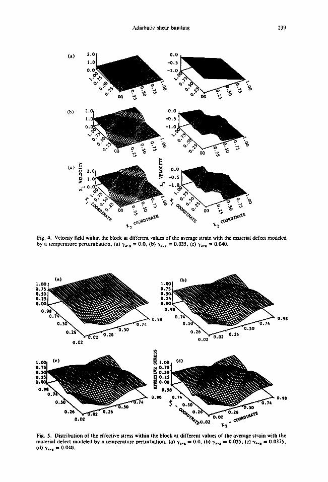
remainder of the material. This contrast between the velocity field in separate regions becomes sharper (e.g. see Fig. 4c) as the deformation becomes more localized.
The variation of the effective stress se, defined as being equal to the left-hand side of eqn (2.12), within the block at "Yavg = 0.0, 0.035, 0.0375 and 0.040 is plotted in Figs. 5a through 5d. Initially the effective stress is lower within the material sur- rounding the center o f temperature perturbation because it is computed from the pre- scribed velocity and temperature fields. Since se satisfies eqn (2.12), the initially higher temperature around (0.0, 0.375) reduces the flow stress needed there to deform the material plastically. Even though the values o f both the temperature and I are higher within the band as compared to those in the surrounding material, the effect of ther- mal softening exceeds the material hardening due to strain-rate effects, and the effec- tive stress within the band is lower than that in the rest of the material. The plots of se and the velocity field suggest that the band first forms along the shorter side of the parallelogram that passes through the center of the temperature bump. Also the mag- nitude of the deformation within the band along the four sides of the parallelogram is not the same.
Adiabatic shear banding 239
(a) 2 . r l . I
0.1
%
0O
(b) 2.
t .
0.
%
~. -
/ • o ".a oooe"_ L oo
7"'2.-
Fig. 4. Velocity field within the block at different values of the average strain with the material defect modeled by a temperature perturabation, (a) Vl~g = 0.0, (b) -yav~ = 0.035, (c) ~'av8 = 0.040.
l.O0 0.75 0.50 0.25 0.00
O. 0.9
0.02
O ' S O 0 ~ " 7~
0.02
U.UL
0 .98
0.98
Fig. 5. Distribution o f the effective stress within the block at different values o f the average strain with the material defect modeled by a temperature perturbat ion, (a) Viv, -- 0.0, (b) rays = 0.035, (c) rays -- 0.0375, (d) "Yavs -- 0.040.
240 R.C. BATRA and D-S. LIu
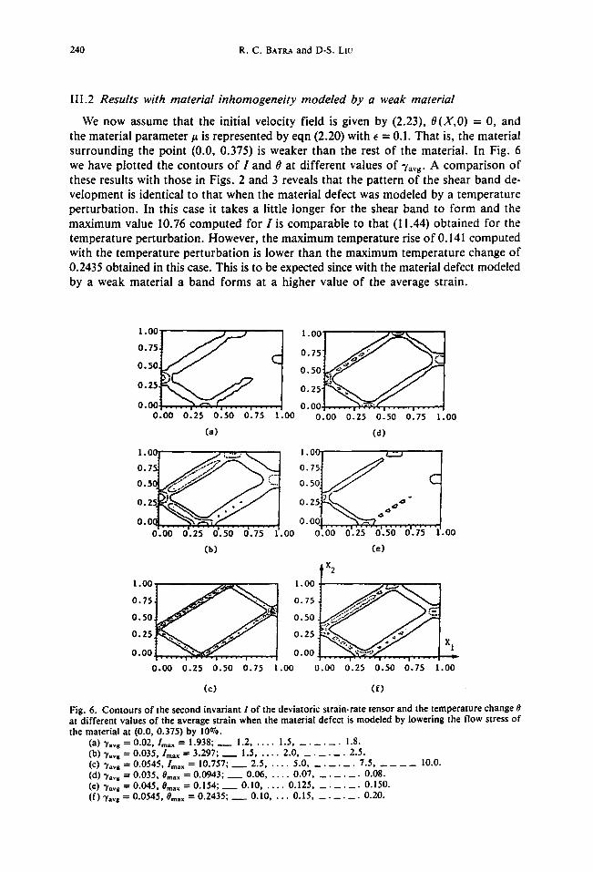
I I I . 2 Results with material inhomogeneity modeled by a weak material
We n o w a s s u m e t h a t the in i t ia l ve loc i t y f ie ld is g iven by (2.23), O(X,O) = 0, a n d
the m a t e r i a l p a r a m e t e r / ~ is r e p r e s e n t e d by e q n (2.20) wi th e = 0.1. T h a t is, the m a t e r i a l
s u r r o u n d i n g the p o i n t (0.0, 0 .375) is w e a k e r t h a n the rest o f t he m a t e r i a l . In Fig. 6
we h a v e p lo t t ed the c o n t o u r s o f I a n d 0 at d i f f e r e n t va lues o f 3'avs- A c o m p a r i s o n o f
these resul t s w i th t h o s e in Figs . 2 a n d 3 r evea l s t ha t the p a t t e r n o f the shea r b a n d de-
v e l o p m e n t is i den t i ca l to t ha t w h e n the m a t e r i a l de fec t was m o d e l e d by a t e m p e r a t u r e
p e r t u r b a t i o n . In th is case it t akes a l i t t le l o n g e r f o r the shea r b a n d to f o r m a n d the
m a x i m u m v a l u e 10.76 c o m p u t e d fo r I is c o m p a r a b l e to tha t (11.44) o b t a i n e d fo r the
t e m p e r a t u r e p e r t u r b a t i o n . H o w e v e r , t he m a x i m u m t e m p e r a t u r e r ise o f 0.141 c o m p u t e d
wi th the t e m p e r a t u r e p e r t u r b a t i o n is l o w e r t h a n the m a x i m u m t e m p e r a t u r e c h a n g e o f
0.2435 o b t a i n e d in this case. This is to be expec ted since with the mate r ia l defec t m o d e l e d
by a w e a k m a t e r i a l a b a n d f o r m s at a h i g h e r v a l u e o f the a v e r a g e s t ra in .
1oo i t l oo . . . . . o,,1 o.7,t / J 7
o.ool . . . . . , - , . ~ . : , . . . . . , . . o . o o I ~ 4 . . . . , . . . . . ! 0.00 0.25 0.50 0.75 1.00 0.00 0.25 0..50 0.75 1.00
Ca) (d)
1 .00 | . ~ ' ;..-~-," ~ I 1. O0 / ~ I 1 o . , ~ ~ ~ A o ,o~ "-1
o.oo o.~~ o.~o o . i ; ~.oo o . o ~ . o,.-,.~o,.~o., o,.. ;...,I. oo (b) Ce)
x 2
0.75 0.75
o 5 o ~ ~ Z 1 o,o o . ~ , ~ . ~ . . . . . f ~ I o.~
x 1 o.ooi . . . . . ~ - . ' ~ ' - < . . . . . . - . . . . I o.oo . . . . . , . . . . . , . . . . . , . . . . . . . , _
0.00 0.25 0.50 0.7:5 l . o o 0.00 0.25 0.50 0.7.5 1.oo
(c) ( f )
Fig. 6. Contours of the second invariant I of the deviatoric strain-rate tensor and the temperature change 0 at different values of the average strain when the material defect is modeled by lowering the flow stress of the material at (0.0, 0.375) by 10%.
(a) 3'avs = 0.02,/max -- 1.938; w 1.2 . . . . . 1.5 . . . . . . . 1.8. (b) ~'avs = 0.035,/max = 3.297; _ _ 1.5 . . . . . 2.0 . . . . . . . 2.5. (c) 7avs = 0.0545, lm~ x = 10.757; ~ 2.5 . . . . . 5.0 . . . . . . . 7.5 . . . . . . 10.0. (d) "rays ---- 0.035, Ore,,,, ----" 0.0943, _ _ 0.06 . . . . . 0.07 . . . . . . . 0.08. (e) 3'ava = 0.045, 0ma~ = 0.154; _ _ 0.10 . . . . . 0.125 . . . . . . . 0.150. (f) 3"a~g = 0.0545, 0ma~ = 0.2435; _ _ 0.10 . . . . 0.15 . . . . . . . 0.20.
Adiabatic shear banding 241
The plots of the velocity field and the effective stress look similar to those shown in Figs. 4 and 5, and are therefore omitted.
The determination of the equivalent amplitudes of the temperature perturbation and the weakness in the material parameter/~ in the sense that the two will result in the formation of the shear band at the same value of the average strain is laborious and has not been attempted here.
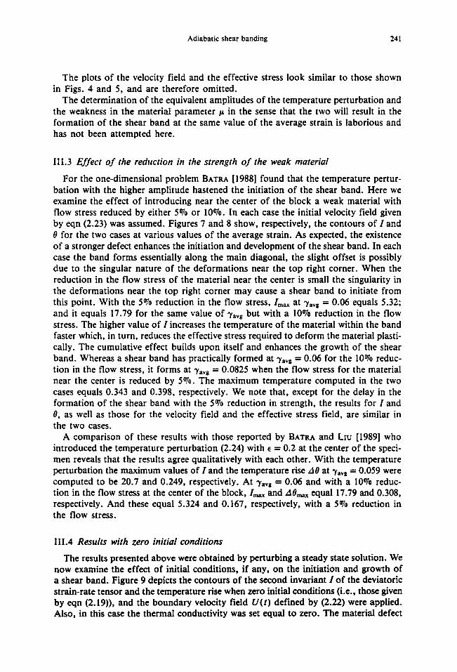
III.3 Effect o f the reduction in the strength of the weak material
For the one-dimensional problem Baa't~, [1988] found that the temperature pertur- bation with the higher amplitude hastened the initiation of the shear band. Here we examine the effect of introducing near the center of the block a weak material with flow stress reduced by either 5070 or 10°70. In each case the initial velocity field given by eqn (2.23) was assumed. Figures 7 and 8 show, respectively, the contours of I and 0 for the two cases at various values of the average strain. As expected, the existence of a stronger defect enhances the initiation and development of the shear band. In each case the band forms essentially along the main diagonal, the slight offset is possibly due to the singular nature of the deformations near the top right corner. When the reduction in the flow stress of the material near the center is small the singularity in the deformations near the top right corner may cause a shear band to initiate from this point. With the 5a70 reduction in the flow stress,/max at "tavB = 0.06 equals 5.32; and it equals 17.79 for the same value of "Yavg but with a 10°70 reduction in the flow stress. The higher value of I increases the temperature of the material within the band faster which, in turn, reduces the effective stress required to deform the material plasti- cally. The cumulative effect builds upon itself and enhances the growth of the shear band. Whereas a shear band has practically formed at -yavg = 0.06 for the 1007o reduc- tion in the flow stress, it forms at ~a~g = 0.0825 when the flow stress for the material near the center is reduced by 507o. The maximum temperature computed in the two cases equals 0.343 and 0.398, respectively. We note that, except for the delay in the formation of the shear band with the 5070 reduction in strength, the results for I and 0, as well as those for the velocity field and the effective stress field, are similar in the two cases.
A comparison of these results with those reported by BATRA and Ln: [1989] who introduced the temperature perturbation (2.24) with ~ = 0.2 at the center of the speci- men reveals that the results agree qualitatively with each other. With the temperature perturbation the maximum values of I and the temperature rise 40 at 3'a~s = 0.059 were computed to be 20.7 and 0.249, respectively. At "Ya~s = 0.06 and with a 1007o reduc- tion in the flow stress at the center of the block,/max and AOmax equal 17.79 and 0.308, respectively. And these equal 5.324 and 0.167, respectively, with a 507o reduction in the flow stress.
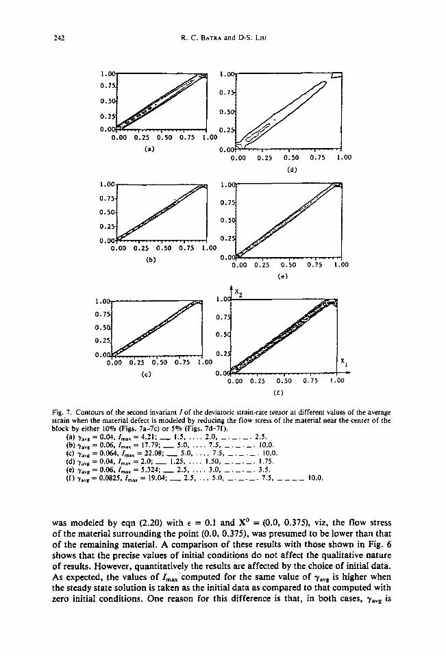
III.4 Results with zero initial conditions
The results presented above were obtained by perturbing a steady state solution. We now examine the effect of initial conditions, if any, on the initiation and growth of a shear band. Figure 9 depicts the contours of the second invariant I of the deviatoric strain-rate tensor and the temperature rise when zero initial conditions (i.e., those given by eqn (2.19)), and the boundary velocity field U(t) defined by (2.22) were applied. Also, in this case the thermal conductivity was set equal to zero. The material defect
242 R . C . BATRAand D-S. L z u
l - ° ° t o., t 0 " 5 5 ~ ~
0 . 2
0 0C~ . ' - ~ . . . . , . . . . . , . . . . . , . . . . . 0.00
l . O0
0.75
0.50
0.23 0.25 0.50 0.75 1 .00
(a)
1.00, - ,
°"°l . f I
0 . 0 0 0 . 2 5 0 . 5 0 0 . 7 5 l .O0
(b)
0 . 0 0 .00 0.25 0.50 0.75 1.00
(a)
1 . 0 C
0.75
0.5C
0.25
O.OC p.O0 0.25 0.50 0.75 1 .00
(e)
x 2
0 . 5 0 .5 (
0 . 2
0 . 0 n ~ C T . . . , . . . . . , - - - ,L. : l 0.2. ' 0 . 0 0 0 . 2 5 0 . 5 0 0 . 7 5 1 .00 X 1
(c ) 0 . o ( . . . . . . . . . . . . . . . . . . . . . o . o o 0 . 2 5 0 . 5 0 0 . 7 5 1 .oo
(r)
Fig. 7. Contours of the second invar iant I o f the deviatoric strain-rate tensor at different values of the average s t ra in when the ma te r i a l defect is mode l ed by reduc ing the f low stress o f the mate r ia l near the center o f the b lock by e i ther 10% (Figs. 7a -7c) or 5 % (Figs. 7d -7 f ) .
(a) 3'avg = 0.04, lma~ = 4.21; _ _ 1.5 . . . . . 2.0 . . . . . . . 2.5. (b) ~'=vg = 0.06, /max = 17.79; _ _ 5.0 . . . . . 7.5 . . . . . . . 10.0. (C) "y=vS = 0.064, Im=~ = 22.08; _ _ 5.0 . . . . . 7.5 . . . . . . . 10.0. (d) 2"avg = 0.04, l,,a~ = 2.0; _ _ ! .25 . . . . . 1.50 . . . . . . . ! .75. (e) ")'~8 = 0.06, /max = 5.324; m 2.5 . . . . . 3 .0 . . . . . . . 3.5. ( f ) ~,=~s = 0.0825, l m ~ = 19.04; ~ 2.5 . . . . 5.0 . . . . . . . 7.5 . . . . . i0 .0 .
was modeled by eqn (2.20) with e = 0.1 and X ° = (0.0, 0.375), viz, the flow stress o f the material surrounding the point (0.0, 0.375), was presumed to be lower than that o f the remaining material. A comparison of these results with those shown in Fig. 6 shows that the precise values of initial conditions do not affect the qualitative nature of results. However, quantitatively the results are affected by the choice of initial data. As expected, the values of/max computed for the same value of Vavg is higher when the steady state solution is taken as the initial data as compared to that computed with zero initial conditions. One reason for this difference is that, in both cases, "yavg is

Adiabatic shear banding 243
1oo .... ill0o 0 . 7 5 ] / ~ " 0 .75
0.50 0 .50
0 " 2 5 L ~ 0.25
O.OOp~, . . . . , . . . . . , . . . . . , . . . . . 0 .00 0 .25 0 .50 0 .75 1.00
(a)
1 . 0 0
0.75
0 .50
0.25
0 . 0 0
. . . . 1. O0
~ . ~ 0.75
/ / i o.'o 0.25
• l ~ - ' - i . . . . . e . . . . . t . . . . : [
.00 0 ,25 0 .50 0 .75 1.00
(b)
l . O O f • .~.... 1.00
0751 o,5 o o! / 7 1 o 0 . 2 5 ~ 0 ..... , ..... 0 2 5
0.00 0.25 0.50 0.75 1.00
m
0.00 0.25 0.50 0.75 1.00
(d) / " 0 .00 0 .25 0 .50 0 .75 1.00
( e )
112
i t !
X 1
0 .00 0 .25 0 .50 0 .75 1.O0 (c)
( f )
Fig. 8. Contours o f the temperature rise 0 at different values of the average strain when the material defect is modeled by reducing the Now stress of the material near the center of the block by either 10% (Figs. 8a-8c) or 5% (Figs. 8d-8f) .
(a) 3'avs = 0.045, 0max = 0.149; ~ 0.10 . . . . . 0.1125 . . . . . . . 0.1250. (b) V*vs = 0.05, 0max = 0.192; ~ 0.10 . . . . . 0.125 . . . . . . . 0.150. (C) "Yavg = 0.063, 0max = 0.343; ~ 0.15 . . . . . 0.20 . . . . . . . 0.25 . . . . . 0.30. (d) "Y,,vs = 0.045, O,,,,x = 0.099; ~ _ _ 0.08. (e) "y,~g = 0.065, 0,~,,~ = 0.2113; _ _ 0.125 . . . . . 0.150 . . . . . . . 0.175. ( f) "Ya,,I = 0.0825, Om,x = 0.3984; _ _ 0.15 . . . . 0.20 . . . . . . . 0.25 . . . . . 0.30.
taken to be zero at time t - 0. The difference is reduced somewhat because of neglect= ing the heat transfer due to conduction. Setting k = 0 should result in a slightly higher temperature locally than would be obtained if k were positive. The higher temperature softens the material more which, in turn, results in higher values of L What effect the thermal conductivity has on the computed results has not yet been ascertained. For the one-dimensional simple shearing problem, B A ~ [1987b] used a constitutive rela- tion similar to eqn (2.4) and found that the thermal conductivity had very little effect on the initiation of the shear band. However, MmtZER [1983] used BoD~R and P,~- TOM'S [1975] constitutive relation and found that the thermal conductivity significantly affects the width of the shear band.
244 R.C. BATRA and D-S. LIu
1.00
0.7
0.2. ~ 0.0(
o / - ' oo . . . . . ' . . . . . ' 0.25 0.50 0.75 . v o
(a)
o7: 0.5(
0.2! 0 . 0 ( , , , ,
0.00 0.25 0.50 0.75 1.00 (e)
' ° ° t 0 . ~ ~ 0.5
0.2
0.0 0.00 0.25 0.50 0.75 1.(
(b)
1.00
O. 75 I ~ 0.50 0.25
°'°°o.ooo~2~ '6.%"bi~"i.~ (e)
1.00
0.75. 0.50 i 0.25i O.OC
0.00 . . . . . i . . . . . s . . . . . I . . . . .
0.25 0.50 0.75 1.00
x 2 1.00
0.75
0.50
0.25
0.00 . . . . . . . . . . . . . . . . . . . . 0.00 0.25 0.50 0.75
(c) ( f )
X 1
1.00
Fig. 9. Contours of the second invariant i of the deviatoric strain-rate tensor and the temperature change 0 at different values of the average strain when the material defect is modeled by reducing the flow stress of the material by 10%, taking zero initial conditions and setting the thermal conductivity k = 0.
(a) "Yavg = 0.035,/max = 2.39; ~ 1.25 . . . . . 1.50 . . . . . . . 1.75. (b) ray8 = 0.055, /max = 9.68; _ _ 2.50 . . . . . 3.75 . . . . . . . 5.00. (C) "tavg = 0.065, Ima x = 12.47; ~ 5.0 . . . . . 7.5 . . . . . . . 10.0. (d) "Ya~g = 0.04, 0rnax = 0.1; _ _ 0.075 . . . . . 0.085 . . . . . . . 0.095. (e) ~',vg = 0.055, 0max = 0.211; _ _ 0.10 . . . . . 0.15 . . . . . . . 0.20. (f) ?avg = 0.065, 0m~ = 0.310; _ _ 0.15 . . . . 0.20 . . . . . . . 0.25.
I I I . 5 M a t e r i a l d a m a g e as a s o f t e n i n g m e c h a n i s m
T h e r e s u l t s p r e s e n t e d t h u s f a r h a v e c o n s i d e r e d t h e m a t e r i a l s o f t e n i n g c a u s e d b y t h e
r i se in i t s t e m p e r a t u r e . A n o t h e r p o s s i b l e s o f t e n i n g m e c h a n i s m is t h e n u c l e a t i o n , coa l e s -
c e n c e a n d g r o w t h o f v o i d s a n d / o r c r a c k s in t h e b o d y . O n e w a y t o m o d e l t h i s is t o
i n t r o d u c e a n i n t e r n a l p a r a m e t e r ~ w h o s e r a t e o f e v o l u t i o n d is a f u n c t i o n o f t h e h i s -
t o r y o f d e f o r m a t i o n a n d / o r p l a s t i c w o r k i n g . I f w e a s s u m e t h a t ~ is a f u n c t i o n o f t h e
p l a s t i c w o r k i n g a n d t h e m a t e r i a l s o f t e n i n g c a u s e d b y ~ c a n b e a d e q u a t e l y r e p r e s e n t e d
b y l o w e r i n g t h e f l o w s t r e s s b y (1 - 0~) w h e r e 0 is a m a t e r i a l p a r a m e t e r , t h e n w e m a y
w r i t e
Adiabatic shear banding 245
= A(l -- O~p)L)iy~)ij(1 -I- bI)m/(pr~f3I), (4.2)
o'ij = - f l ( p -- 1)(Sij + ( l / , J - 3 I ) ( l + b [ ) m ( l - O$)D i j , (4.3)
where A is a constant. In this case the results of section 4.4 may be thought of as repre- senting the dynamic development of an adiabatic shear band in plane strain compres- sion of a viscoplastic block when the material softening mechanism is the internal damage caused by plastic working.
IV. CONCLUSIONS
The development of a shear band in plane strain compression of a block made of a thermally softening viscoplastic material being deformed at an overall strain-rate of 5,000 sec -~ has been studied. The results computed when the material defect is modeled by perturbing the steady-state solution for a homogeneous body (a) with a superimposed temperature bump, and (b) with the introduction of a weaker material agree with each other qualitatively. The qualitative nature of the results remains un- changed even when zero initial conditions are assumed and the transient problem solved.
When the material defect is on the vertical axis of symmetry and away from the cen- ter of the block, a shear band initiates from the site of the defect, it propagates along the direction of maximum shearing and is reflected back from the boundaries, the an- gle of reflection being nearly equal to the angle of incidence. The shear stress within the band is considerably lower than that in the surrounding material. The eventual de- velopment of the band along the sides of the parallelogram divides the block into five regions. The velocity field within each region varies linearly and sharp gradients in the velocity field occur at the sides of the parallelogram.
We add that the conclusions drawn above are strictly valid for the constitutive model used herein. However, similar results were obtained by N~DLE~4~,~ [1989], LEMO~'DS and NEEDT-E~',~ [1986a,1986b] and A ~ D et al. [1988] who used different constitu- tive relations and the latter two papers ignored the effect of inertia forces. Possibly sharper results could be obtained by using a finer mesh and/or a different space of trial solutions and test functions.
Acknowledgments--This work was supported by the U.S. National Science Foundation grant MSM-8715952 and the U.S. Army Research Office Contract DAAL03-88K-OI84 to the University of Missouri-Rolla.
REFERENCES
1934 T^YtoR, G.I. and QUISNEY, H., "The Latent Energy Remaining in a Metal After Cold Working," Proc. Roy. Soc. A 413, 307.
1944 ZENm~, C. and HOLLOMON, J.H., "Effect of Strain Rate on Plastic Flow of Steel," J. Appl. Phys., lS, 22.
1968 BELL, J.F., Physics of Large Deformations of Crystalline Solids, Springer-Verlag, New York. 1975 BODNm~, S.R. and P~TOM, Y., "Constitutive Equations for Elastic-Viscoplastic Strain Hardening
Materials," J. Appl. Mechs., 42, 385. 1979 RoGm~s, H.C., "Adiabatic Plastic Deformation," Ann. Rev. Mat. Sci., 9, 23. 1980 CLWrON, R.J., "Material Response to Ultra High Loading Rates," NRC National Material Advi-
sory Board (U.S.) Report 356. 1980 COSTn% L.S., C m s ~ , E.E., I-IAW~V, R.H., and D~ln~, J., "On the Localization of Plastic Flow
in Mild Steel Tubes Under Dynamic Torsional Loading," in H~U)ING, J. (¢d.), Mechanical Prop- erties at High Rates of Strain, Proc. 2nd Oxford Conf. Inst. Phys., London, 90-100.
246 R.C. BATRA and D-S. L~u
1981 BM, Y.L., "A Criterion for Thermoplastic Shear Instability," in MEYERS, M.A. and MURR, L.E. (eds.), Shock Waves and High Strain Rate Phenomenon in Metals, Plenum Press, New York, 277-283.
1981 Moss, G.L., "Shear Strain, Strain Rates, and Temperature Changes in Adiabatic Shear Bands," in MEYEt~s, M.A. and Mu'~t, L.E. (eds.), Shock Waves and High Strain Rate Phenomenon in Met- als, Plenum Press, New York, 229-312.
1981 Zm~Emwlcz, O.C., ORATE, E. and HEmpacH, J.C., "A General Formulation for Coupled Ther- mal Flow of Metals using Finite Elements," Int. J. Num. Meth. Engng., 17, 1497.
1982 B^~m, K.J., Finite Element Procedures in Engineering Analysis, Prentice Hall, Inc., Engiewood, N.J. 1983 Ln, rDHOt~, U.S. and J o n s o n , G.R., "Strain-Rate Effects in Metals at Large Strain-Rates," in MES-
cmL J. and WEISS, V. (eds.), Material Behavior Under High Stress and Ultrahigh Loading Rates, Plenum Press, New York, 61-79.
1983 MERZER, A.M., "Modelling of Adiabatic Shear Band from Small Imperfections," J. Mech. Phys. Solids, 30, 323.
1983 ROGERS, H.C., "A Review of Adiabatic Shearing," in MESCALL, J. and WEIss, V. (eds.), Material Behavior Under High Stress and Ultrahigh Loading Rates, Plenum Press, New York, 101-118.
1984 CLIV'rON, R.J., Du~Y, J., HARTLEY, K.A., and SHAWKI, T.G., "On Critical Conditions for Shear Band Formation at High Strain Rates," Scripta Metall., 18, 443.
1984 Wu, F.H. and Ft~UND, L.B., "Deformation Trapping due to Thermoplastic Instability in One-Di- mensional Wave Propagation," J. Mech. Phys. Sol., 32, 119.
1985 BURNS, T. J., "Approximate Linear Stability Analysis of a Model of Adiabatic Shear Band Forma- tion," Quart, Appl. Math., 43, 65.
1985 COLEM~q, B.D. and Ho~3Dos, M.L., "On Shear Bands in Ductile Materials," Arch. Rat'l Mech. Anal., 90, 219.
1985 WnIGHT, T.W. and B^TRA, R.C., "Adiabatic Shear Bands in Simple and Dipolar Plastic Materi- als," in Proc. IUTAM Syrup. On Macro- and Micro-Mechanics of High Velocity Deformation and Fracture, Aug. 1985, Kawata, K. and Shiori, J. (eds.), Springer-Verlag, NY, 1987, 189-201.
1986a LEMONDS, J. and NEEDLEMA.S, A., "Finite Element Analysis of Shear Localization in Rate and Tem- perature Dependent Solids," Mechs. Materials, 5, 339.
1986b LEMONDS, J. and NEEDLEMAS, A., "An Analysis of Shear Band Development Incorporating Heat Conduction," Mechs. Materials, 5, 363.
1986 LI~, M.R. and WAGONER, R.H., "Effect of Temperature, Strain, and Strain-Rate on the Tensile Flow Stress of I.F. Steel and Stainless Steel Type 310," Scripta Metall., 20, 143.
1987a B^T~, R.C., "The Initiation and Growth of, and the Interaction Among Adiabatic Shear Bands in Simple and Dipolar Materials," Int. J. Plast., 3, 75.
1987b BA~tA, R.C., "Effect of Material Parameters on the Initiation and Growth of Adiabatic Shear Bands," Int. J. Solids Structures, 23, 1435.
1987 H^RTLEY, K.A., DUFFY, J., and HAWLEY, R.H., "Measurement of the Temperature Profile During Shear Band Formation in Steels Deforming at High Strain Rates," J. Mech. Phys. Solids, 35, 283.
1987 Tn~oTw¢, S.P., "The Structure of Adiabatic Shear Bands in Metals: A Critical Review," Acta Metail., 35, 301.
1987 WRIGHT, T.W. and WALTER, J., "On Stress Collapse in Adiabatic Shear Bands," J. Mech. Phys. Sol., 35, 701.
1988 BATRA, R.C., "Steady State Penetration of Thermoviscoplastic Targets," Comp. Mechs., 3, 1. 1988 MARCttA~D, A. and DUVFV, J., "An Experimental Study of the Formation of Adiabatic Shear Bands
in a Structural Steel," J. Mech. Phys. Solids, 36, 251. 1988 AsA,~D, L., LUSH, A.M., and KIM, K.H., "Thermal Aspects of Shear Localization in Viscoplastic
Solids," in ATTI^, M.H. and KoPs, L. (eds.), Thermal Aspects in Manufacturing, ASME-PED- Vol. 30, 89-103.
1988 SmJ'rrLE, D.A. and S~UTH, I.M., "Numerical Simulation of Shear Band Formation in Soils," Int. J. Num. Anaiyt. Methods Geomechanics, 12, 611.
1988 Zsm, H.M. and AIFANTIS, E.C., "On the Structure and Width of Shear Bands," Scripta Metall., 22, 703.
1989 BATRA, R.C. and LIu, DE-Sm~, "Adiabatic Shear Banding in Plane Strain Problems," J. Appl. Mechs., 56, 527.
1989 NEEDLEMAN, A., "Dynamic Shear Band Development in Plane Strain," J. Appl. Mechs., 56, 1. 1990 B^T~A, R.C. and IOM, C.H., "Adiabatic Shear Banding in Elastic-Viscoplastic Nonpolar and Dipolar
Materials," Int. J. Plast. 6, 127-141.
Department of Mechanical and Aerospace Engineering and Engineering Mechanics University of Missouri-Rolla Rolla, MO 65401, USA
(Received 6 February 1989; in Final rev/sed form 16 June 1989)