AddPac Technology Digital E1/T1 Voice Module Installation ... · Digital E1/T1 Voice Module...
97
Digital E1/T1 Voice Module Installation Guide [Data, Voice, Video & IP Telephony Solution] August, 2005. AddPac Technology Co. , Ltd. Technical Sales Division www.addpac.com
Transcript of AddPac Technology Digital E1/T1 Voice Module Installation ... · Digital E1/T1 Voice Module...
Digital E1/T1 Voice Module
Installation Guide [Data, Voice, Video & IP Telephony Solution]
August, 2005.
AddPac Technology Co. , Ltd. Technical Sales Division
www.addpac.com

Digital E1/T1 Voice Module Installation Guide (Release 1.00E) Aug. 2005
AddPac Technology Proprietary & Documentation 97 - 2
Note. The specifications and information in this guide are subject to change without notice. All statements, information, and recommendations in this guide are believed to be accurate but are presented without warranty of any kind, express or implied. In no event shall AddPac or its suppliers disclaim all warranties, expressed or implied, including, without limitation, lost profits or loss or damage to data arising out of the use or inability to use this guide. For detail specification, information or sales and warranty, please contact to AddPac Technical Sales division.
Digital E1/T1 Voice Module Installation Guide (Release 1.00E) Aug. 2005
AddPac Technology Proprietary & Documentation 97 - 3
[ INDEX ]
Chapter 1. Overview............................................................8
Preface ...................................................................................................................................8
Release History............................................................................................................8
Guide Organization ......................................................................................................9
Additional Information ..................................................................................................9
Consulting Service .......................................................................................................9
Digital Voice Internetworking Products Profiles ..............................................................10
Digital E1/T1 VoIP Products .......................................................................................10
Product Features (Digital E1/T1)................................................................................10
Digital E1/T1 Voice Module Features.........................................................................13
AddPac Technology VoIP Internetworking Solution ...................................................15
APOS Internetworking Software........................................................................................16
APOS Overview .........................................................................................................16
Product Highlights ......................................................................................................16
Chapter 2. Installation and Configuration ...................18
Cable connection .......................................................................................................18
LOS/ACT LEDs ..........................................................................................................18
Call Test .....................................................................................................................19
Configuration Examples.....................................................................................................20
ISDN-PRI command...................................................................................................20
R2/DTMF PRI command............................................................................................23
Chapter 3. APOS Commands ........................................26
E1/T1 signaling type...................................................................................................26
Clock Master/Slave ....................................................................................................28
Digital E1/T1 Slave-main............................................................................................30
Channel Ascending/Descending ................................................................................31
Compand-type [ulaw/Alaw /au-law/ua-law] ................................................................32
ISDN-PRI Overlap......................................................................................................33
ISDN-PRI Network/User Mode...................................................................................34
ISDN-PRI Overlap-sending ........................................................................................35
ISDN PRI Numbering-type .........................................................................................37
R2-MFC Overlap ........................................................................................................40
R2-MFC Get-Calling-Number.....................................................................................41
Digital E1/T1 Voice Module Installation Guide (Release 1.00E) Aug. 2005
AddPac Technology Proprietary & Documentation 97 - 4
Channel based Out-bound Call block ........................................................................41
E1/T1 Signaling Interface Debug COmmands ...........................................................42
Chapter 4. APOS Command Configuration...............53
ISDN-PRI Signaling .............................................................................................................53
R2/DTMF Signaling .............................................................................................................57
Chapter 5. Digital Voice Module.....................................60
Chapter 6. Appendix .........................................................63
ISDN Signaling Standard....................................................................................................63
ISDN Signaling structure............................................................................................63
ISDN Layer 3 protocol................................................................................................65
R2 Signaling Standard........................................................................................................76
MFC-R2 signaling ......................................................................................................76
Signaling System .......................................................................................................76
Line Signal .................................................................................................................77
Register Signal...........................................................................................................78
Usage Guideline.........................................................................................................85
Glossary...............................................................................................................................86

Digital E1/T1 Voice Module Installation Guide (Release 1.00E) Aug. 2005
AddPac Technology Proprietary & Documentation 97 - 5
[ Table List ] [Table 1-1] Installation Guide Release Description..................................................................8
[Table 1-2] Installation Guide Organization .............................................................................9
[Table 1-3] Digital E1/T1 Voice Module Features ..................................................................13
[Table 2-1] Digital E1 ISDN-PRI configuration.......................................................................20
[Table 2-2] Digital T1 ISDN-PRI configuration .......................................................................21
[Table 2-3] ISDN-PRI configuration commands.....................................................................23
[Table 2-4] Digital E1 R2/DTMF configuration .......................................................................24
[Table 2-5] Digital T1 R2-DTMF configuration .......................................................................24
[Table 2-6] R2/DTMF configuration commands.....................................................................25
[Table 3-1] Signaling type configuration ................................................................................26
[Table 3-2] Signaling type configuration commands..............................................................26
[Table 3-3] Clock Master/Slave configuration........................................................................28
[Table 3-4] Clock Master/Slave configuration commands .....................................................29
[Table 3-5] Clock slave main configuration............................................................................30
[Table 3-6] Clock slave main configuration commands .........................................................31
[Table 3-7] Channel Ascending/Descending configuration....................................................31
[Table 3-8] Channel Ascending/Descending configuration commands .................................32
[Table 3-9] Compand type configuration................................................................................32
[Table 3-10] Compand Type configuration commands ..........................................................33
[Table 3-11] ISDN-PRI overlap configuration.........................................................................33
[Table 3-12] ISDN-PRI Overlap configuration commands .....................................................34
[Table 3-13] ISDN-PRI Interface protocol setting ..................................................................34
[Table 3-14] ISDN-PRI protocol setting commands...............................................................35
[Table 3-15] ISDN-PRI Overlap-Sending configuration .........................................................36
[Table 3-16] ISDN-PRI Overlap-sending configuration commands .......................................37
[Table 3-17] ISDN-PRI Numbering-type configuration...........................................................38
[Table 3-18] ISDN-PRI Numbering-type configuration commands........................................38
[Table 3-19] R2-MFC Overlap configuration..........................................................................40
[Table 3-20] R2-MFC Overlap configuration commands .......................................................40
[Table 3-21] R2-MFC Get-Calling-Number configuration ......................................................41
[Table 3-22] R2-MFC Get-Calling-Number configuration commands....................................41
[Table 3-23] Out-barred-group configuration .........................................................................42
[Table 3-24] Out-barred-group configuration commands.......................................................42
[Table 3-25] Digital E1/T1 debug commands ........................................................................43
[Table 3-26] Digital E1/T1 ISDN-PRI debug (Call-setup).......................................................43
[Table 3-27] Digital E1/T1 R2-MFC debug (Call-setup).........................................................47

Digital E1/T1 Voice Module Installation Guide (Release 1.00E) Aug. 2005
AddPac Technology Proprietary & Documentation 97 - 6
[Table 4-1] Digital E1/T1 ISDN-PRI configuration..................................................................53
[Table 4-2] Show Interface Command for ISDN PRI .............................................................54
[Table 4-3] Digital E1/T1 configuration commands................................................................56
[Table 4-4] Digital E1/T1 R2/DTMF configuration..................................................................57
[Table 4-5] Show Inteface Command for R2/DTMF ..............................................................58
[Table 4-6] R2/DTMF Configuration commands....................................................................59
[Table 5-1] Digital Voice Modules ..........................................................................................60
[Table 6-1] SAPI and TEI assignment ...................................................................................64
[Table 6-2] ISDN signaling channel combination...................................................................65
[Table 6-3] Q.931 messages .................................................................................................66
[Table 6-4] R2-MFC Signal Transmission..............................................................................78
[Table 6-5] MFC Call Spec.(ITU-T R2) ..................................................................................79
[Table 6-6] MFC Call Spec.(Korea ver R2) ............................................................................79
[Table 6-7] MFC Call Spec.(ITU-T R2) ..................................................................................80
[Table 6-8] MFC Call Spec.(Korea ver. R2)...........................................................................81
[Table 6-9] R2 End-to-End Signaling Procedure ...................................................................82
[Table 6-10] R2 Link-by-Link Signaling Procedure ................................................................83
[Table 6-11] Called party’s Option .........................................................................................84
[Table 6-12] Calling number identification .............................................................................85
Digital E1/T1 Voice Module Installation Guide (Release 1.00E) Aug. 2005
AddPac Technology Proprietary & Documentation 97 - 7
[ Figure List ] (Figure 1-1) AddPac Technology Internetworking Solution ...................................................15
(Figure 1-2) APOS Diagram ..................................................................................................16
(Figure 2-1) LOS/ACT LEDs .................................................................................................18
(Figure 3-1) Digital E1/T1 ISDN-PRI Sending Diagram ........................................................35
(Figure 3-2) ISDN-PRI Numbering-type Diagram..................................................................38
(Figure 4-1) Network Diagram for ISDN-PRI setup...............................................................53
(Figure 4-2) Network Diagram for E1/T1 R2/DTMF setup.....................................................57
(Figure 6-1) ISDN Call control (Q931)...................................................................................66
(Figure 6-2) ISDN Message Structure...................................................................................67
(Figure 6-3) Single octet information element format ............................................................69
(Figure 6-4) Single octet information elements .....................................................................69
(FIgure 6-5) Variable length information element ..................................................................69
(FIgure 6-6) Information element identifier ............................................................................70
(Figure 6-7) Call Establishment Phase..................................................................................71
(Figure 6-8) Call Information Phase ......................................................................................71
(Figure 6-9) Call Clearing Phase...........................................................................................71
(Figure 6-10) Miscellaneous..................................................................................................71

Digital E1/T1 Voice Module Installation Guide (Release 1.00E) Aug. 2005
AddPac Technology Proprietary & Documentation 97 - 8
Chapter 1. Overview
Preface
This guide offers information of AddPac Technology’s digital E1/T1 voice module installation and configuration. Various kinds of digital E1/T1 voice modules are designed to be equipped on module slot on VoIP products and to be upgradable on user’s need with good extensibility and easy maintainance. This guide shows coverage and functions of each signaling on AddPac’s digital voice module for E1/T1 interface, setup guidance, related commands and examples. User can have a thorough grasp of the problem at installation and operation, and cope that, with having understand AddPac’s VoIP gateway which supports digital voice module and E1/T1 signaling. Please refer to 『APOS Quick Operation Guide』for general installation, not mentioned in this guide.
Release History
The release history of digital E1/T1 voice module installation guide is as follows.
[Table 1-1] Installation Guide Release Description
Title Release No. Date Content Written By Digital E1/T1 Voice Module
Configuration Guide
1.00E Aug, 2005 Initial
Released
AddPac
R&D Center

Digital E1/T1 Voice Module Installation Guide (Release 1.00E) Aug. 2005
AddPac Technology Proprietary & Documentation 97 - 9
Guide Organization
This guide contaions the following chapters:
[Table 1-2] Installation Guide Organization
Section Title Description
Chapter 1 Overview • Introduction, revision history and AddPac’s
Internetworking Solutions
• Introduction on APOS™ Internetworking Software
Chapter 2 Installation and Configuration • Digital voice module installation and basic
configuration
Chapter 3 APOS Commands • Summary and explaination of APOS commands for
digital voice module
Chapter 4 APOS Command Configuration • Examples of APOS commands for digital E1/T1 voice
module
Chapter 5 E1/T1 Digital Voice Interface
Module
• AddPac’s digital voice module specifitaions for E1/T1
Chapter 6 Appendix • ISDN signaling standard
• R2 signaling standard
• Glossary
Additional Information
For more informations on this internetworking solution, training and others, contact AddPac Technical sales division. It is available from Monday to Friday (9:00AM ~ 7:00PM, GMT+8:00, Tel:+82 2 568 3848, Fax:+82 2 568 3847). Also, feel free to send e-mails to [email protected] for world-wide technical supports.
Consulting Service
AddPac Technology supports various technical consulting, specific network planning. This service is for optimized AddPac Technologies internetworking solution with seperation, integration, interworking of different kinds of network environment such as data, voice, video, security, multimedia, IP telephony. It will increase business competiveness through consulting service for the network design, planning in customer’s current network environment. For Inquiries and consulting service, please do not hesitate to ack us from Monday to Friday (9:00AM ~ 7:00PM, GMT+8:00, Tel:+82 2 568 3848, Fax:+82 2 568 3847). Also, feel free to send e-mails to [email protected] for the advanced technical supports.

Digital E1/T1 Voice Module Installation Guide (Release 1.00E) Aug. 2005
AddPac Technology Proprietary & Documentation 97 - 10
Digital Voice Internetworking Products Profiles
Digital E1/T1 VoIP Products
AddPac’s various VoIP products such as media gateway, VoIP gateway and VoIP router support the digital E1/T1 voice interface modules. These products provide complete connectivity with other vendor’s VoIP gateway, general commercialized PBX(PABX), PSTN switch on diverse digital E1/T1 standard signaling. Make stable and reliable network environment with various products listed below. For the products that are not mentioned in this guide, please contact AddPac Technologies technical sales division.
Product Features (Digital E1/T1)
[Table1-3] Product Features
Category Model Key Specifications AP2110 Enterprise-level VoIP Gateway
1U x 19inch Rack-mountable Hardware chassis 1-port 10/100M fast-Ethernet WAN 1-port 10M Ethernet LAN 1-port PSTN backup 1-port RS-232C console 1 Voice interface module slot (Module) 4~8-port FXS/FXO/E&M Analog voice (Module) Multichannel Voice/Audio/MP3 broadcasting (Module) 1-port Digital E1(30channel) Voice (Module) 1-port Digital T1(24channel) Voice Built-in AC110~220V Power supplier APOS Internetworking Software
VoIP Gateway Products VoIP Gateway IP Centric VoIP Gateway
AP2520G Enterprise-level VoIP Gateway 1U x 19inch Rack-mountable Hardware chassis 1-port 10/100M fast-Ethernet WAN 1-port 10M Ethernet LAN 1-port RS-232C console 2 Voice interface module slot (Module) 4~8-port FXS/FXO/E&M Analog voice (Module) Multichannel Voice/Audio/MP3 broadcasting (Module) 1-port Digital E1(30channel) Voice (Module) 1-port Digital T1(24channel) Voice Built-in AC110~220V Power supplier APOS Internetworking Software

Digital E1/T1 Voice Module Installation Guide (Release 1.00E) Aug. 2005
AddPac Technology Proprietary & Documentation 97 - 11
AP2620 Enterprise-level VoIP Gateway 1U x 19inch Rack-mountable Hardware chassis 2-port 10/100M fast-Ethernet WAN 1-port RS-232C console 2 Voice interface module slot (Module) 4~8-port FXS/FXO/E&M Analog voice (Module) Multichannel Voice/Audio/MP3 broadcasting (Module) 1-port Digital E1(30channel) Voice (Module) 1-port Digital T1(24channel) Voice Built-in AC110~220V Power supplier APOS Internetworking Software (IPv4/IPv6)
AP2650 Enterprise-level VoIP Gateway 1.75U x 19inch Rack-mountable hardware chassis 1 CPU interface module slot 4 Voice interface module slot (Module) CPU interface module, 2-port 10/100M fast-Ethernet, 1-port RS-232C console, status LED (Module) 8~32-port FXS/FXO/E&M Analog voice (Module) 1/2-port Digital E1(30/60channel) Voice (Module) 1/2-port Digital T1(24/48channel) Voice Built-in AC110~220V Power supplier (Dual) APOS Internetworking Software (IPv4/IPv6)
AP-MG3000
Media Gateway 1.5U x 19inch Rack-mountable Hardware chassis 120 Status LEDs (on Front Pannel) 1 Network interface module slot 2 Digital voice interface module slot (Module) AP-2LAN Network interface module, 2-port 10/100M fast-Ethernet, 1-port RS-232C console, 1-port Asyn. AUX Serial (Module) 1-port Digital E1(30channel) Voice (Module) 1-port DIgital T1(24channel) Voice (Module) 2-port Digital E1(60channel) Voice (Module) 2-port Digital T1(48channel) Voice (Module) 4-port Digital E1(120channel) Voice (Module) 4-port Digital T1(96channel) Voice Built-in AC110~220V Power supplier APOS Internetworking Software (IPv4/IPv6)
VoIP Networking Products Media Gateway
AP-MG5000 Premium Media Gateway
3U x 19inch Rack-mountable Hardware chassis 1 System interface module slot 4 Digital voice interface module slot (System Interface Module) 2-port 10/100/100M Gigabit Ethernet, 6-port 10/100M fast-Ethernet, 1-port RS-232C console (Module) 2-port Digital E1/T1 Voice (Module) 4-port Digital E1/T1 Voice Built-in AC110~220V Power supplier (Dual, detatchable) APOS Internetworking Software (IPv4/IPv6)
Digital E1/T1 Voice Module Installation Guide (Release 1.00E) Aug. 2005
AddPac Technology Proprietary & Documentation 97 - 12
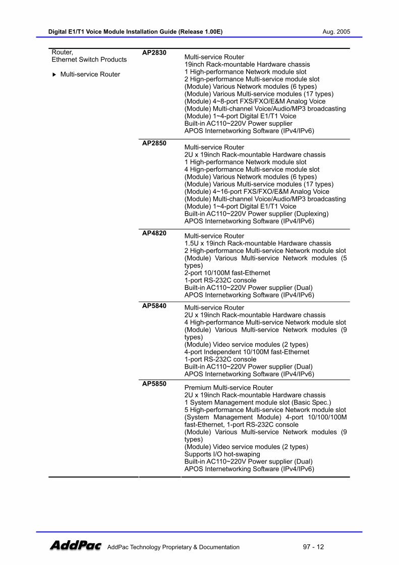
AP2830 Multi-service Router 19inch Rack-mountable Hardware chassis 1 High-performance Network module slot 2 Hign-performance Multi-service module slot (Module) Various Network modules (6 types) (Module) Various Multi-service modules (17 types) (Module) 4~8-port FXS/FXO/E&M Analog Voice (Module) Multi-channel Voice/Audio/MP3 broadcasting(Module) 1~4-port Digital E1/T1 Voice Built-in AC110~220V Power supplier APOS Internetworking Software (IPv4/IPv6)
AP2850 Multi-service Router 2U x 19inch Rack-mountable Hardware chassis 1 High-performance Network module slot 4 Hign-performance Multi-service module slot (Module) Various Network modules (6 types) (Module) Various Multi-service modules (17 types) (Module) 4~16-port FXS/FXO/E&M Analog Voice (Module) Multi-channel Voice/Audio/MP3 broadcasting(Module) 1~4-port Digital E1/T1 Voice Built-in AC110~220V Power supplier (Duplexing) APOS Internetworking Software (IPv4/IPv6)
AP4820 Multi-service Router 1.5U x 19inch Rack-mountable Hardware chassis 2 High-performance Multi-service Network module slot(Module) Various Multi-service Network modules (5 types) 2-port 10/100M fast-Ethernet 1-port RS-232C console Built-in AC110~220V Power supplier (Dual) APOS Internetworking Software (IPv4/IPv6)
AP5840 Multi-service Router 2U x 19inch Rack-mountable Hardware chassis 4 High-performance Multi-service Network module slot(Module) Various Multi-service Network modules (9 types) (Module) Video service modules (2 types) 4-port Independent 10/100M fast-Ethernet 1-port RS-232C console Built-in AC110~220V Power supplier (Dual) APOS Internetworking Software (IPv4/IPv6)
Router, Ethernet Switch Products Multi-service Router
AP5850 Premium Multi-service Router 2U x 19inch Rack-mountable Hardware chassis 1 System Management module slot (Basic Spec.) 5 High-performance Multi-service Network module slot(System Management Module) 4-port 10/100/100M fast-Ethernet, 1-port RS-232C console (Module) Various Multi-service Network modules (9 types) (Module) Video service modules (2 types) Supports I/O hot-swaping Built-in AC110~220V Power supplier (Dual) APOS Internetworking Software (IPv4/IPv6)
Digital E1/T1 Voice Module Installation Guide (Release 1.00E) Aug. 2005
AddPac Technology Proprietary & Documentation 97 - 13
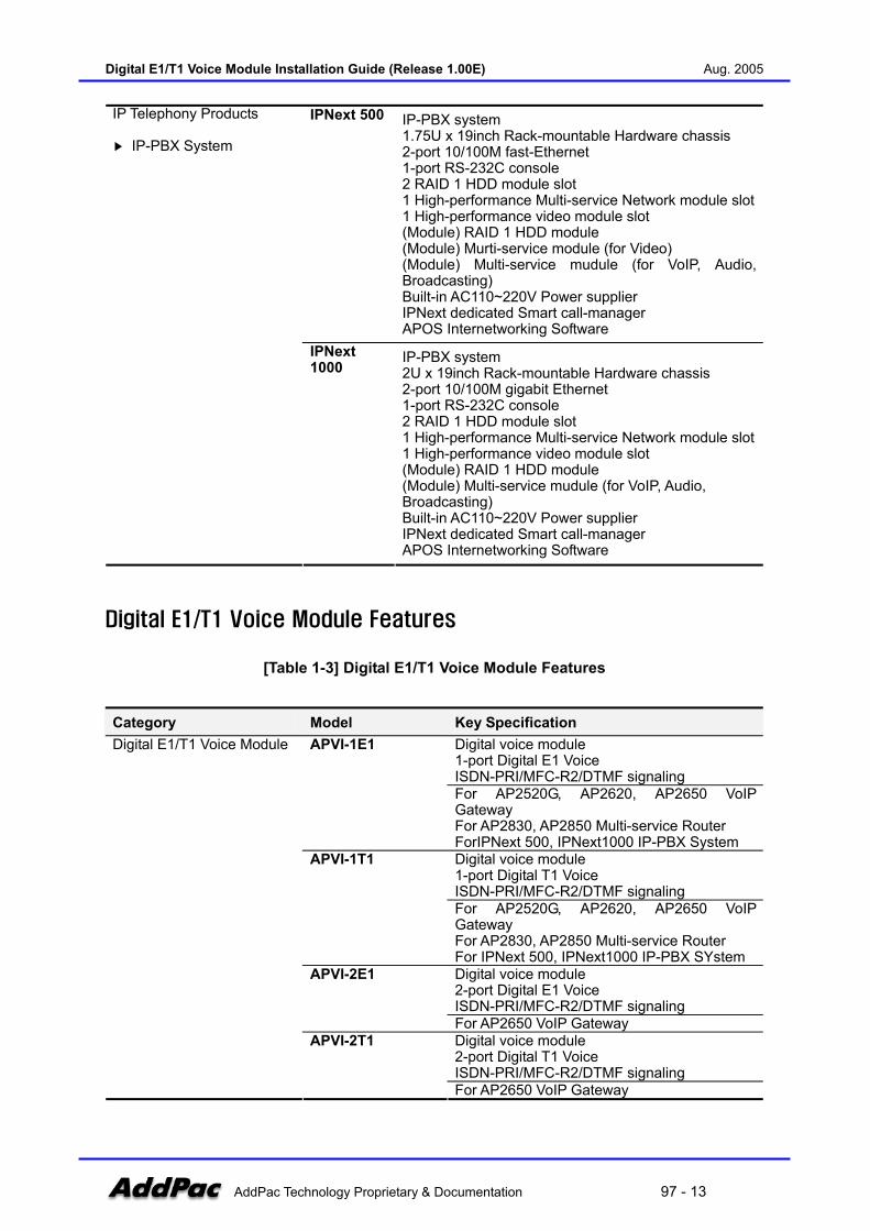
IPNext 500 IP-PBX system 1.75U x 19inch Rack-mountable Hardware chassis 2-port 10/100M fast-Ethernet 1-port RS-232C console 2 RAID 1 HDD module slot 1 High-performance Multi-service Network module slot1 High-performance video module slot (Module) RAID 1 HDD module (Module) Murti-service module (for Video) (Module) Multi-service mudule (for VoIP, Audio, Broadcasting) Built-in AC110~220V Power supplier IPNext dedicated Smart call-manager APOS Internetworking Software
IP Telephony Products IP-PBX System
IPNext 1000
IP-PBX system 2U x 19inch Rack-mountable Hardware chassis 2-port 10/100M gigabit Ethernet 1-port RS-232C console 2 RAID 1 HDD module slot 1 High-performance Multi-service Network module slot1 High-performance video module slot (Module) RAID 1 HDD module (Module) Multi-service mudule (for VoIP, Audio, Broadcasting) Built-in AC110~220V Power supplier IPNext dedicated Smart call-manager APOS Internetworking Software
Digital E1/T1 Voice Module Features
[Table 1-3] Digital E1/T1 Voice Module Features
Category Model Key Specification Digital voice module 1-port Digital E1 Voice ISDN-PRI/MFC-R2/DTMF signaling
APVI-1E1
For AP2520G, AP2620, AP2650 VoIP Gateway For AP2830, AP2850 Multi-service Router ForIPNext 500, IPNext1000 IP-PBX System Digital voice module 1-port Digital T1 Voice ISDN-PRI/MFC-R2/DTMF signaling
APVI-1T1
For AP2520G, AP2620, AP2650 VoIP Gateway For AP2830, AP2850 Multi-service Router For IPNext 500, IPNext1000 IP-PBX SYstem Digital voice module 2-port Digital E1 Voice ISDN-PRI/MFC-R2/DTMF signaling
APVI-2E1
For AP2650 VoIP Gateway Digital voice module 2-port Digital T1 Voice ISDN-PRI/MFC-R2/DTMF signaling
Digital E1/T1 Voice Module
APVI-2T1
For AP2650 VoIP Gateway
Digital E1/T1 Voice Module Installation Guide (Release 1.00E) Aug. 2005
AddPac Technology Proprietary & Documentation 97 - 14
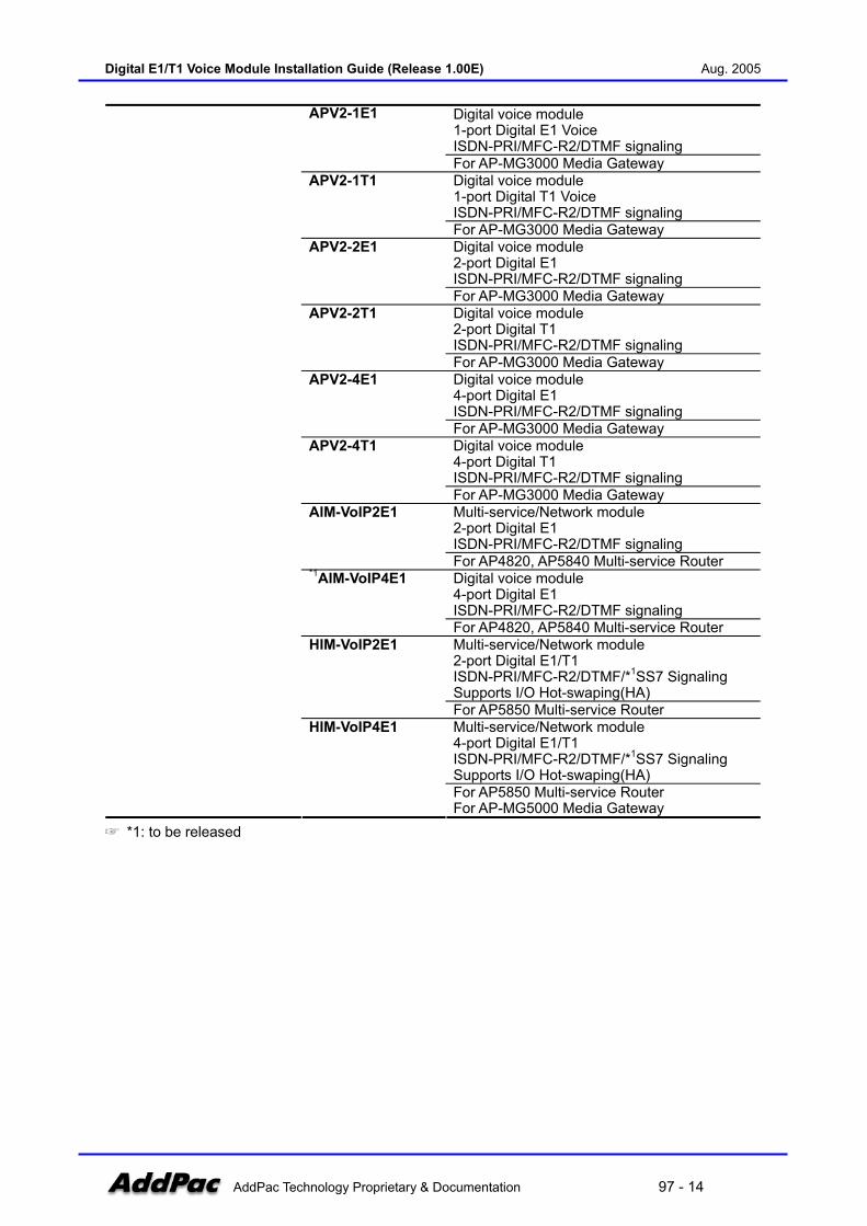
Digital voice module 1-port Digital E1 Voice ISDN-PRI/MFC-R2/DTMF signaling
APV2-1E1
For AP-MG3000 Media Gateway Digital voice module 1-port Digital T1 Voice ISDN-PRI/MFC-R2/DTMF signaling
APV2-1T1
For AP-MG3000 Media Gateway Digital voice module 2-port Digital E1 ISDN-PRI/MFC-R2/DTMF signaling
APV2-2E1
For AP-MG3000 Media Gateway Digital voice module 2-port Digital T1 ISDN-PRI/MFC-R2/DTMF signaling
APV2-2T1
For AP-MG3000 Media Gateway Digital voice module 4-port Digital E1 ISDN-PRI/MFC-R2/DTMF signaling
APV2-4E1
For AP-MG3000 Media Gateway Digital voice module 4-port Digital T1 ISDN-PRI/MFC-R2/DTMF signaling
APV2-4T1
For AP-MG3000 Media Gateway Multi-service/Network module 2-port Digital E1 ISDN-PRI/MFC-R2/DTMF signaling
AIM-VoIP2E1
For AP4820, AP5840 Multi-service Router Digital voice module 4-port Digital E1 ISDN-PRI/MFC-R2/DTMF signaling
*1AIM-VoIP4E1
For AP4820, AP5840 Multi-service Router Multi-service/Network module 2-port Digital E1/T1 ISDN-PRI/MFC-R2/DTMF/*1SS7 Signaling Supports I/O Hot-swaping(HA)
HIM-VoIP2E1
For AP5850 Multi-service Router Multi-service/Network module 4-port Digital E1/T1 ISDN-PRI/MFC-R2/DTMF/*1SS7 Signaling Supports I/O Hot-swaping(HA)
HIM-VoIP4E1
For AP5850 Multi-service Router For AP-MG5000 Media Gateway
*1: to be released

Digital E1/T1 Voice Module Installation Guide (Release 1.00E) Aug. 2005
AddPac Technology Proprietary & Documentation 97 - 15
AddPac Technology VoIP Internetworking Solution
AddPac Technology’s internetworking solution products offer high performance networking solutions not only for voice but also for data, video, multimedia and IP telephony network applications. The following figure shows the overall AddPac’s internetworking products and access networking solutions.
(Figure 1-1) AddPac Technology Internetworking Solution
AddPac’s internetworking products include VoIP Gateway, Media Gateway, IP Broadcasting System, Multi-service Router, Ethernet Switch and Video Equipments delivering a seamless integration of multimedia network of voice, data and video. Moreover, AddPac is newly focusing on Next Gneration Network Products such as IP-PBX, IP-Phone, IP-Video Phone and Call Manager to provide ALL-IP solution to the customers worldwide.
Digital E1/T1 Voice Module Installation Guide (Release 1.00E) Aug. 2005
AddPac Technology Proprietary & Documentation 97 - 16
APOS Internetworking Software
APOS Overview
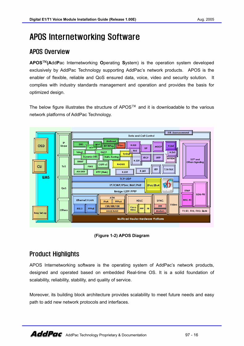
APOS™(AddPac Internetworking Operating System) is the operation system developed exclusively by AddPac Technology supporting AddPac’s network products. APOS is the enabler of flexible, reliable and QoS ensured data, voice, video and security solution. It complies with industry standards management and operation and provides the basis for optimized design. The below figure illustrates the structure of APOS™ and it is downloadable to the various network platforms of AddPac Technology.
(Figure 1-2) APOS Diagram
Product Highlights
APOS Internetworking software is the operating system of AddPac’s network products, designed and operated based on embedded Real-time OS. It is a solid foundation of scalability, reliability, stability, and quality of service. Moreover, its building block architecture provides scalability to meet future needs and easy path to add new network protocols and interfaces.
Digital E1/T1 Voice Module Installation Guide (Release 1.00E) Aug. 2005
AddPac Technology Proprietary & Documentation 97 - 17
Supports industry standard network protocols APOS Internetworking software supports industry standard network protocols. It includes WAN/LAN, ATM network protocols for data networking, voice/data integration protocols such as VoIP and various supplementary protocols of network management, encryption/decryption, ISDN, VPN, video, DVR/VOD, IPv6, and IP telephony.
Multimedia Internetworking solution
APOS Internetworking software not only delivers data networking, but also provides secure multimedia communications and transactions of Voice over Internet Protocol (VoIP), Video and VPN on the integrated systems.
Optimized performance and features
Superior data packet processing and traffic management capability of APOS Internetworking software ensures that AddPac’s network products meet the high standard of the optimized network integration.
Increased Convenience and Maintanance
For easy deployment, APOS Internetworking software supports industry standard Command Line Interface (CLI). Moreover, Web Based Management, Remote Management and EMS interoperability realizes easy management of sophisticated features.
Next generation IP networking, supports Pv4/IPv6
APOS Internetworking software supports not only IPv4 but also IPv6 simultaniously for next generation IP networking environment. APOS IPv4/IPv6 internetworking software conforms to international IPv6 standards certified by IPv6 international standard program(http://www. ipv6ready.org) from IPv6 forum (http://www. ipv6forum. org).
Multimedia based IP Telephony solution
APOS Internetworking software supports various products for next IP telephony networking. It performs wide range of products and standards for complete IP telephony solution such as IP-PBX system, IP video phone, IP phone.
Digital E1/T1 Voice Module Installation Guide (Release 1.00E) Aug. 2005
AddPac Technology Proprietary & Documentation 97 - 18
Chapter 2. Installation and Configuration The setup procedure and operation commands for AddPac digital E1/T1 voice module are as follows.
Pre-configuration
Like as analog VoIP gateway, digital E1/T1 VoIP gateway should assign the IP address, E.164 number, H.323/SIP related VoIP signaling parameter. Also the configuration setting for E1/T1 digital interface is needed. To learn more, please refer to『APOS Quick Operation Guide』and APOS command configuration examples on this guide.
Cable connection
The digital E1/T1 voice interface between two peers is connected using category-5 UTP cable with RJ-45 connector. The RJ-45 connector pin assignment of 1,2/3,4 is to Rx/Tx on PBX respectively.
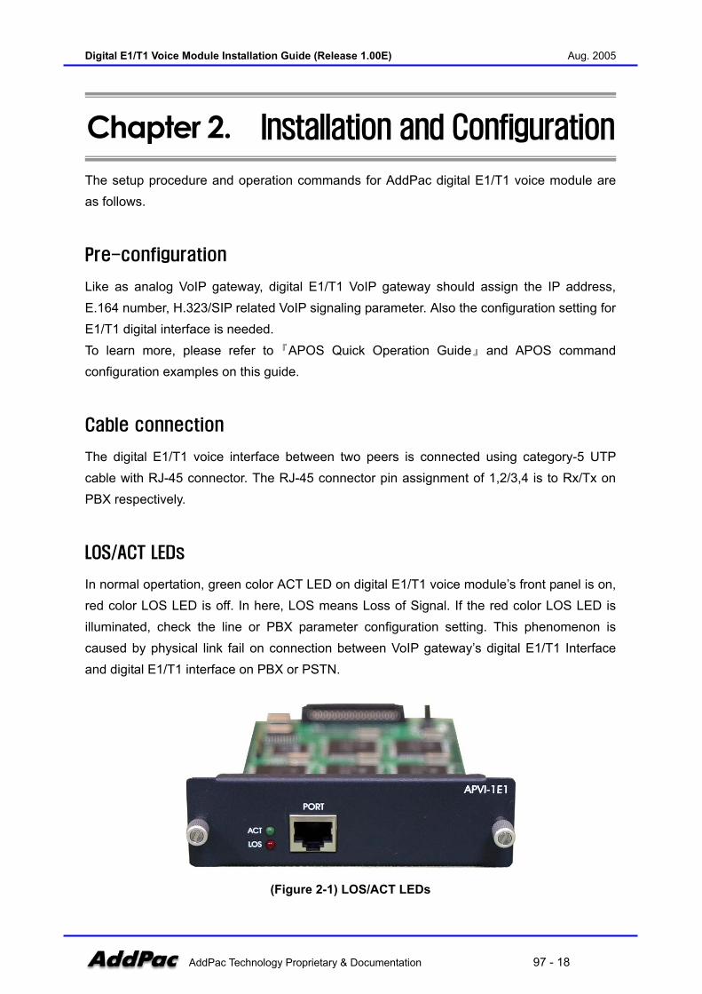
LOS/ACT LEDs
In normal opertation, green color ACT LED on digital E1/T1 voice module’s front panel is on, red color LOS LED is off. In here, LOS means Loss of Signal. If the red color LOS LED is illuminated, check the line or PBX parameter configuration setting. This phenomenon is caused by physical link fail on connection between VoIP gateway’s digital E1/T1 Interface and digital E1/T1 interface on PBX or PSTN.
(Figure 2-1) LOS/ACT LEDs
Digital E1/T1 Voice Module Installation Guide (Release 1.00E) Aug. 2005
AddPac Technology Proprietary & Documentation 97 - 19
If red color LOS LED is on but green color ACT LED is off, check “ISDN protocol-emulation mode” configuration of VoIP gateway and PBX whether there is no problem in physical line connection. For ISDN-PRI mode, set AddPac digital E1/T1 VoIP gateway as “User Side” when ISDN-PRI interface board of PBX is “Network Side”, and PBX as “User Side” when AddPac digital E1/T1 VoIP gateway is “Network Side”.
Call Test
When green color ACT LED is normally operated, it is considered that basic E1/T1 link conection between AddPac E1/T1 VoIP module and PBX or PSTN E1/T1 VoIP Interface is OK. And then, execute call test to check dial-plan and other parameter configuration setting between two end-to-end peers.
Digital E1/T1 Voice Module Installation Guide (Release 1.00E) Aug. 2005
AddPac Technology Proprietary & Documentation 97 - 20
Configuration Examples
AddPac VoIP gateway’s digital E1/T1 module supports two types of signaling for configuring E1/T1 interface such as ISDN–PRI and R2/DTMF.
ISDN-PRI command
WAN(IP Network)
Analog Phone
Router
AddPacVoIP Gateway(Head Office)PBX
Access Code : 8Signaling Type : ISDNClock : MasterNo. of Channels : 30 or 24Compand Type : U LawProtocol : User
Access Code (E.164) : 99Signaling Type : ISDNClock : SlaveNo. of Channels : 30 or 24Compand Type : A-LawProtocol : NetworkVoice Port 0/0IP Address : 192.168.1.1
Digital E1 or T1
Setting ISDN-PRI Command for Digital E1 or T1
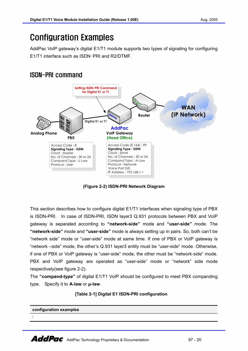
(Figure 2-2) ISDN-PRI Network Diagram
This section describes how to configure digital E1/T1 interfaces when signaling type of PBX is ISDN-PRI. In case of ISDN-PRI, ISDN layer3 Q.931 protocols between PBX and VoIP gateway is separated according to “network-side” mode and “user-side” mode. The “network-side” mode and “user-side” mode is always setting up in pairs. So, both can’t be “network side” mode or “user-side” mode at same time. If one of PBX or VoIP gateway is “network –side” mode, the other’s Q.931 layer3 entity must be “user-side” mode. Otherwise, if one of PBX or VoIP gateway is “user-side” mode, the other must be “network-side” mode. PBX and VoIP gateway are operated as “user-side” mode or “network” side mode respectively(see figure 2-2). The “compand-type” of digital E1/T1 VoIP should be configured to meet PBX companding type. Specify it to A-law or µ-law.
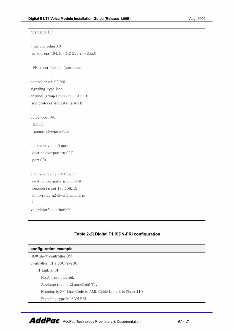
[Table 2-1] Digital E1 ISDN-PRI configuration
configuration examples
!
Digital E1/T1 Voice Module Installation Guide (Release 1.00E) Aug. 2005
AddPac Technology Proprietary & Documentation 97 - 21
hostname HO
!
interface ether0.0
ip address 194.168.1.2 255.255.255.0
!
! PRI controller configuration.
!
controller e1(t1) 0/0
signaling-type isdn
channel-group timeslots 1-31 0
isdn protocol-emulate network
!
voice-port 0/0
! E1(t1)
compand-type u-law
!
dial-peer voice 0 pots
destination-pattern 99T
port 0/0
!
dial-peer voice 1000 voip
destination-pattern 5683848
session target 193.158.1.2
dtmf-relay h245-alphanumeric
!
voip-interface ether0.0
!
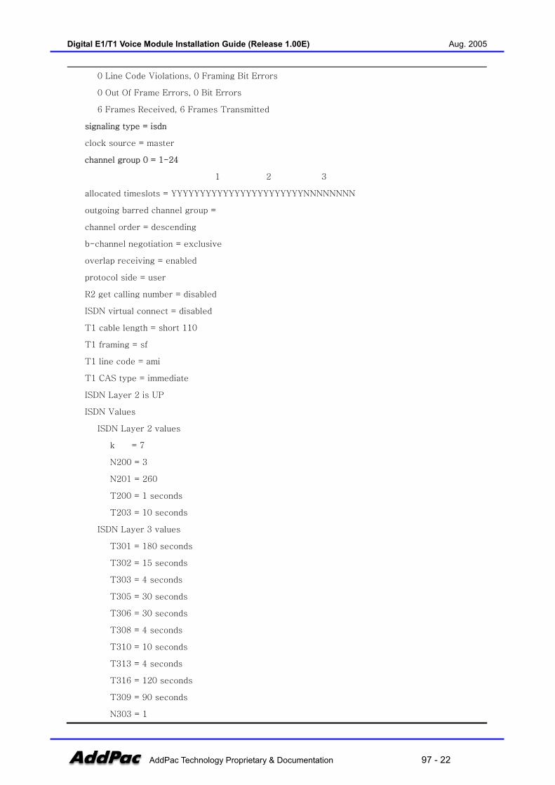
[Table 2-2] Digital T1 ISDN-PRI configuration
configuration example
HO# show controller 0/0
Controller T1 slot(0)/port(0)
T1 Link is UP
No Alarm detected.
Applique type is Channelized T1.
Framing is SF, Line Code is AMI, Cable Length is Short 110.
Signaling type is ISDN PRI.
Digital E1/T1 Voice Module Installation Guide (Release 1.00E) Aug. 2005
AddPac Technology Proprietary & Documentation 97 - 22
0 Line Code Violations, 0 Framing Bit Errors
0 Out Of Frame Errors, 0 Bit Errors
6 Frames Received, 6 Frames Transmitted
signaling type = isdn
clock source = master
channel group 0 = 1-24
1 2 3
allocated timeslots = YYYYYYYYYYYYYYYYYYYYYYYNNNNNNNN
outgoing barred channel group =
channel order = descending
b-channel negotiation = exclusive
overlap receiving = enabled
protocol side = user
R2 get calling number = disabled
ISDN virtual connect = disabled
T1 cable length = short 110
T1 framing = sf
T1 line code = ami
T1 CAS type = immediate
ISDN Layer 2 is UP
ISDN Values
ISDN Layer 2 values
k = 7
N200 = 3
N201 = 260
T200 = 1 seconds
T203 = 10 seconds
ISDN Layer 3 values
T301 = 180 seconds
T302 = 15 seconds
T303 = 4 seconds
T305 = 30 seconds
T306 = 30 seconds
T308 = 4 seconds
T310 = 10 seconds
T313 = 4 seconds
T316 = 120 seconds
T309 = 90 seconds
N303 = 1
Digital E1/T1 Voice Module Installation Guide (Release 1.00E) Aug. 2005
AddPac Technology Proprietary & Documentation 97 - 23
[Table 2-3] ISDN-PRI configuration commands
Step APOS command Purpose
1 HO(config-ether0.0)# controller e1 0/0 Enter E1 interface configuration mode
2 HO(config-controller-e1-0/0)#signaling-type isdn Specify signaling type
3 HO(config-controller-e1-0/0)#channel-group
timeslots 1-31 0
Specify channel group (use all 30
channels)
4 HO(config-ether0.0)# isdn protocol-emulate
Network
5 HO(config-ether0.0)# voice-port 0/0 Start setting up voice port 0/0
6 HO(config-voice-port-0/0)# compand-type u-law Specify compand type (note that this
command is exist under voice-port
configuration CLI(command line
interface) command tree)
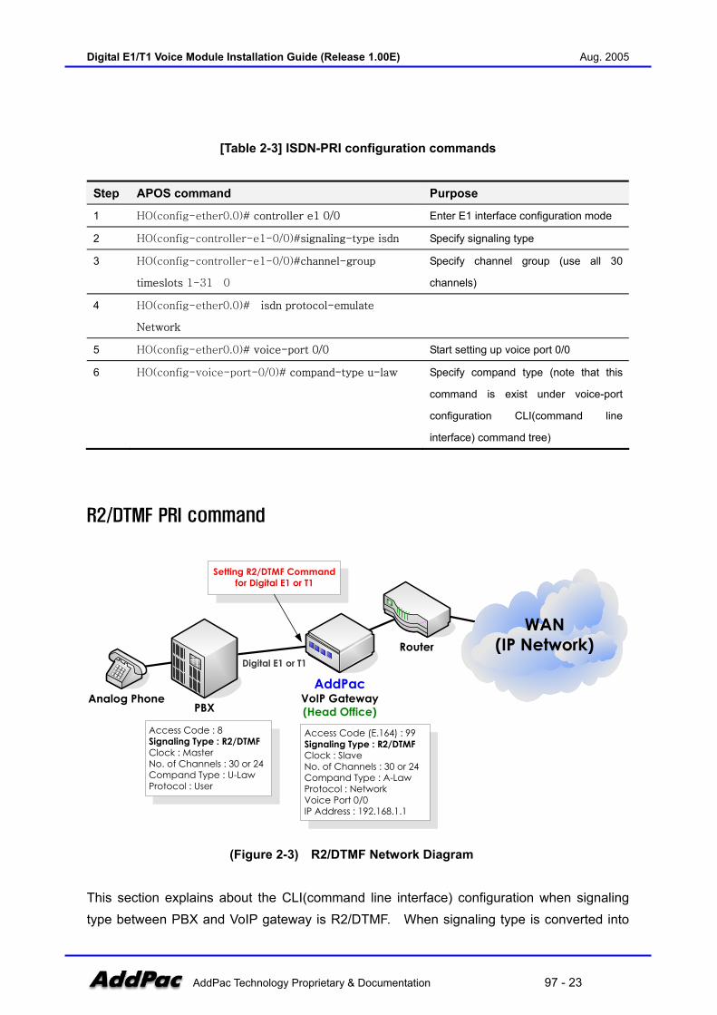
R2/DTMF PRI command
WAN(IP Network)
Analog Phone
Router
AddPacVoIP Gateway(Head Office)PBX
Access Code : 8Signaling Type : R2/DTMFClock : MasterNo. of Channels : 30 or 24Compand Type : U-LawProtocol : User
Access Code (E.164) : 99Signaling Type : R2/DTMFClock : SlaveNo. of Channels : 30 or 24Compand Type : A-LawProtocol : NetworkVoice Port 0/0IP Address : 192.168.1.1
Setting R2/DTMF Command for Digital E1 or T1
Digital E1 or T1
(Figure 2-3) R2/DTMF Network Diagram
This section explains about the CLI(command line interface) configuration when signaling type between PBX and VoIP gateway is R2/DTMF. When signaling type is converted into
Digital E1/T1 Voice Module Installation Guide (Release 1.00E) Aug. 2005
AddPac Technology Proprietary & Documentation 97 - 24
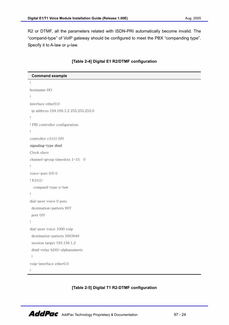
R2 or DTMF, all the parameters related with ISDN-PRI automatically become invalid. The “compand-type” of VoIP gateway should be configured to meet the PBX “companding type”. Specify it to A-law or µ-law.
[Table 2-4] Digital E1 R2/DTMF configuration
Command example
!
hostname HO
!
interface ether0.0
ip address 194.168.1.2 255.255.255.0
!
! PRI controller configuration.
!
controller e1(t1) 0/0
signaling-type dtmf
Clock slave
channel-group timeslots 1-31 0
!
voice-port 0/0 0
! E1(t1)
compand-type u-law
!
dial-peer voice 0 pots
destination-pattern 99T
port 0/0
!
dial-peer voice 1000 voip
destination-pattern 5683848
session target 193.158.1.2
dtmf-relay h245-alphanumeric
!
voip-interface ether0.0
!
[Table 2-5] Digital T1 R2-DTMF configuration
Digital E1/T1 Voice Module Installation Guide (Release 1.00E) Aug. 2005
AddPac Technology Proprietary & Documentation 97 - 25
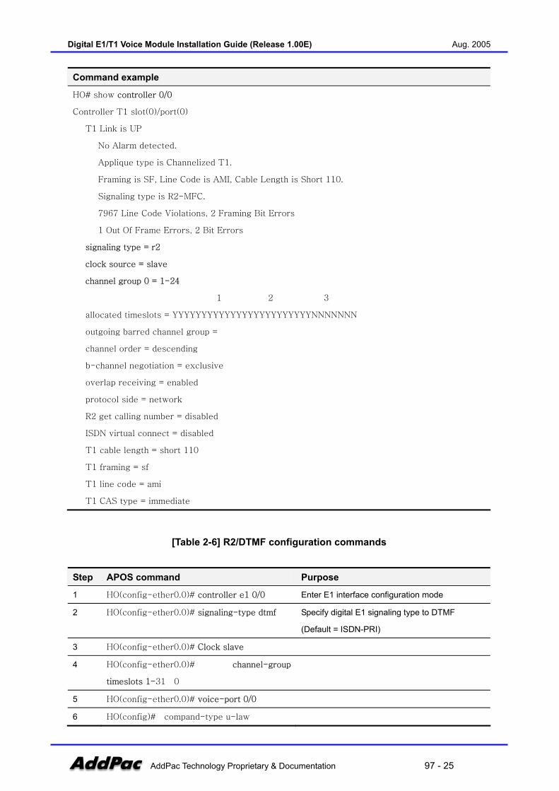
Command example
HO# show controller 0/0
Controller T1 slot(0)/port(0)
T1 Link is UP
No Alarm detected.
Applique type is Channelized T1.
Framing is SF, Line Code is AMI, Cable Length is Short 110.
Signaling type is R2-MFC.
7967 Line Code Violations, 2 Framing Bit Errors
1 Out Of Frame Errors, 2 Bit Errors
signaling type = r2
clock source = slave
channel group 0 = 1-24
1 2 3
allocated timeslots = YYYYYYYYYYYYYYYYYYYYYYYYNNNNNNN
outgoing barred channel group =
channel order = descending
b-channel negotiation = exclusive
overlap receiving = enabled
protocol side = network
R2 get calling number = disabled
ISDN virtual connect = disabled
T1 cable length = short 110
T1 framing = sf
T1 line code = ami
T1 CAS type = immediate
[Table 2-6] R2/DTMF configuration commands
Step APOS command Purpose
1 HO(config-ether0.0)# controller e1 0/0 Enter E1 interface configuration mode
2 HO(config-ether0.0)# signaling-type dtmf Specify digital E1 signaling type to DTMF
(Default = ISDN-PRI)
3 HO(config-ether0.0)# Clock slave
4 HO(config-ether0.0)# channel-group
timeslots 1-31 0
5 HO(config-ether0.0)# voice-port 0/0
6 HO(config)# compand-type u-law
Digital E1/T1 Voice Module Installation Guide (Release 1.00E) Aug. 2005
AddPac Technology Proprietary & Documentation 97 - 26
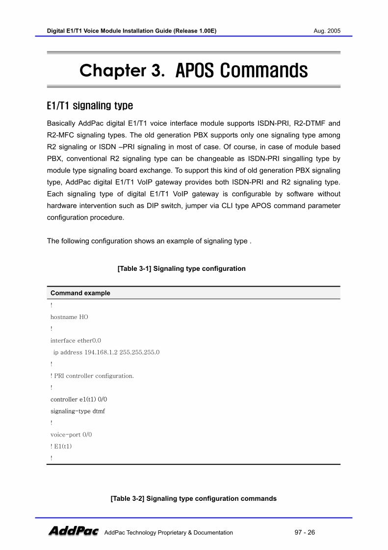
Chapter 3. APOS Commands
E1/T1 signaling type
Basically AddPac digital E1/T1 voice interface module supports ISDN-PRI, R2-DTMF and R2-MFC signaling types. The old generation PBX supports only one signaling type among R2 signaling or ISDN –PRI signaling in most of case. Of course, in case of module based PBX, conventional R2 signaling type can be changeable as ISDN-PRI singalling type by module type signaling board exchange. To support this kind of old generation PBX signaling type, AddPac digital E1/T1 VoIP gateway provides both ISDN-PRI and R2 signaling type. Each signaling type of digital E1/T1 VoIP gateway is configurable by software without hardware intervention such as DIP switch, jumper via CLI type APOS command parameter configuration procedure. The following configuration shows an example of signaling type .
[Table 3-1] Signaling type configuration
Command example
!
hostname HO
!
interface ether0.0
ip address 194.168.1.2 255.255.255.0
!
! PRI controller configuration.
!
controller e1(t1) 0/0
signaling-type dtmf
!
voice-port 0/0
! E1(t1)
!
[Table 3-2] Signaling type configuration commands

Digital E1/T1 Voice Module Installation Guide (Release 1.00E) Aug. 2005
AddPac Technology Proprietary & Documentation 97 - 27
Step APOS command Purpose
1 HO(config-ether0.0)# controller e1 0/0 Enter E1 interface configuration mode
2 HO(config-controller-e1-0/0)# signaling-type
<dtmf | isdn | r2>
Specify Digital E1 Signaling type to DTMF, to
ISDN-PRI or to R2-MFC (Default = ISDN-PRI)

Digital E1/T1 Voice Module Installation Guide (Release 1.00E) Aug. 2005
AddPac Technology Proprietary & Documentation 97 - 28
Clock Master/Slave
To obatin uninterruptable error-free voice channel on digital E1/ T1 trunk between VoIP gateway and PBX, frame synchronization and data clock recovery is very important issue. The error-free accurate data recovery on E1/T1 interface between PBX and VoIP gateway is obtained by clock recovery technology, mechnism such as PLL, clock master/slave between peer-to-peer interface. The “clock-source master” mode and “clock-source slave” mode between PBX and digital VoIP gateway E1/T1 interface is always setting up in pairs. So, both can’t be “clock-source master” mode or “clock-source slave” mode at same time. When clock-source mode is same on peer-to-peer interface, digital E1/T1 frame can be out of sync and occurred LOS(loss of singal) singal, that causes the voice packet loss on digital E1/T1 interface. If the digital E1/T1 interface clock mode in one of PBX or VoIP gateway is “clock-source master” mode, the other’s digital E1/T1 interface must be “clock-source slave” mode. Otherwise, if one of PBX or VoIP gateway is “clock-source slave” mode, the other must be “clock-source master” mode
[Table 3-3] Clock Master/Slave configuration
Command example
!
hostname HO
!
interface ether0.0
ip address 194.168.1.2 255.255.255.0
!
! PRI controller configuration.
!
controller e1(t1) 0/0
clock-source slave
!
voice-port 0/0
! E1(t1)
!
Digital E1/T1 Voice Module Installation Guide (Release 1.00E) Aug. 2005
AddPac Technology Proprietary & Documentation 97 - 29
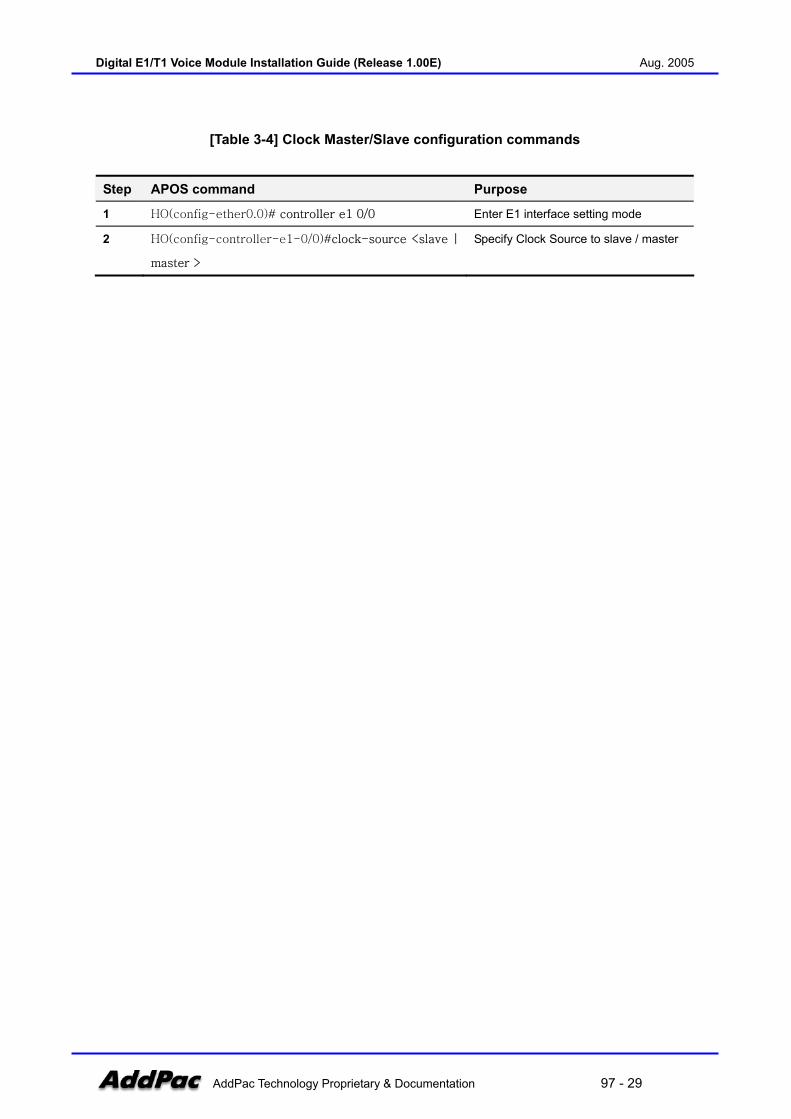
[Table 3-4] Clock Master/Slave configuration commands
Step APOS command Purpose
1 HO(config-ether0.0)# controller e1 0/0 Enter E1 interface setting mode
2 HO(config-controller-e1-0/0)#clock-source <slave |
master >
Specify Clock Source to slave / master
Digital E1/T1 Voice Module Installation Guide (Release 1.00E) Aug. 2005
AddPac Technology Proprietary & Documentation 97 - 30
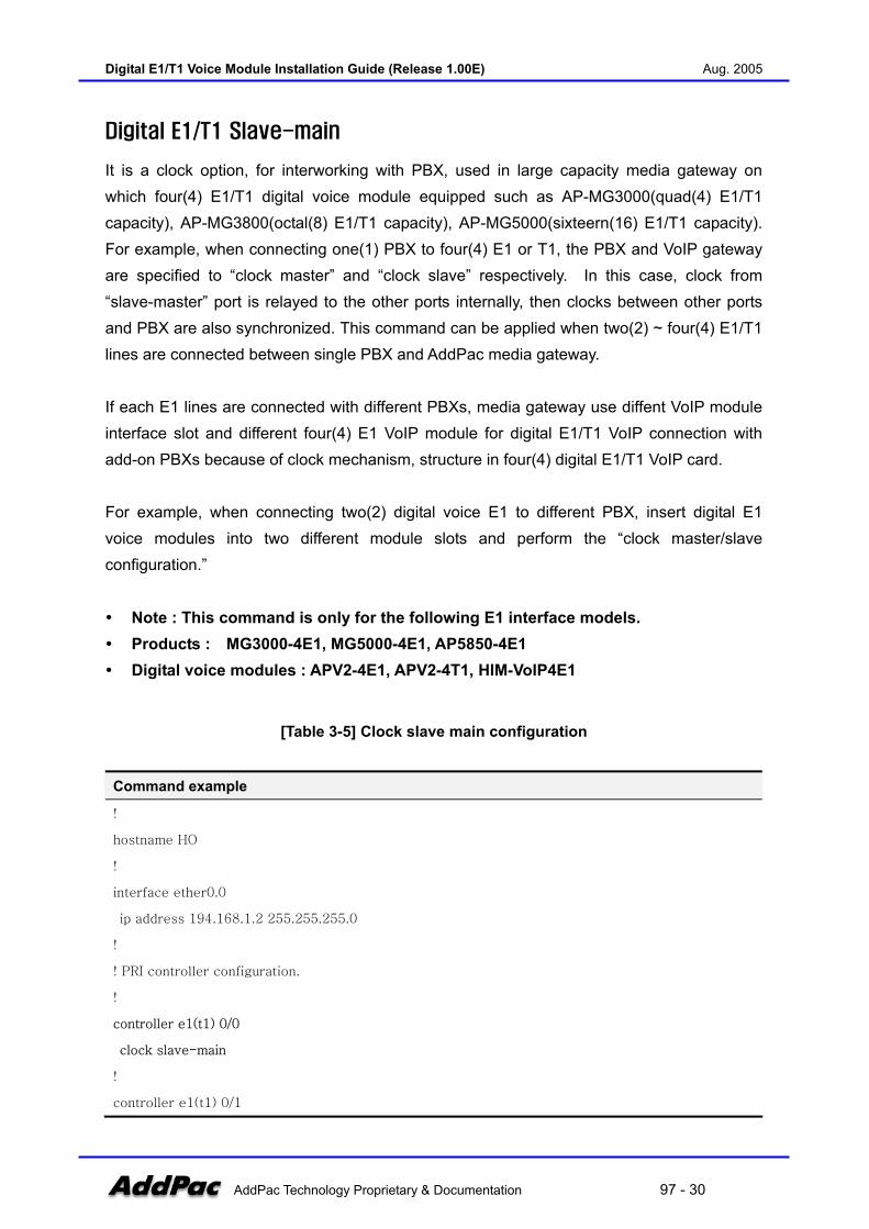
Digital E1/T1 Slave-main
It is a clock option, for interworking with PBX, used in large capacity media gateway on which four(4) E1/T1 digital voice module equipped such as AP-MG3000(quad(4) E1/T1 capacity), AP-MG3800(octal(8) E1/T1 capacity), AP-MG5000(sixteern(16) E1/T1 capacity). For example, when connecting one(1) PBX to four(4) E1 or T1, the PBX and VoIP gateway are specified to “clock master” and “clock slave” respectively. In this case, clock from “slave-master” port is relayed to the other ports internally, then clocks between other ports and PBX are also synchronized. This command can be applied when two(2) ~ four(4) E1/T1 lines are connected between single PBX and AddPac media gateway. If each E1 lines are connected with different PBXs, media gateway use diffent VoIP module interface slot and different four(4) E1 VoIP module for digital E1/T1 VoIP connection with add-on PBXs because of clock mechanism, structure in four(4) digital E1/T1 VoIP card. For example, when connecting two(2) digital voice E1 to different PBX, insert digital E1 voice modules into two different module slots and perform the “clock master/slave configuration.” Note : This command is only for the following E1 interface models. Products : MG3000-4E1, MG5000-4E1, AP5850-4E1 Digital voice modules : APV2-4E1, APV2-4T1, HIM-VoIP4E1
[Table 3-5] Clock slave main configuration
Command example
!
hostname HO
!
interface ether0.0
ip address 194.168.1.2 255.255.255.0
!
! PRI controller configuration.
!
controller e1(t1) 0/0
clock slave-main
!
controller e1(t1) 0/1
Digital E1/T1 Voice Module Installation Guide (Release 1.00E) Aug. 2005
AddPac Technology Proprietary & Documentation 97 - 31
clock slave
!
controller e1(t1) 0/1
clock slave
!
controller e1(t1) 0/1
clock slave
!
!
voice-port 0/0
! E1(t1)
!
[Table 3-6] Clock slave main configuration commands
Step APOS command Purpose
1 HO(config-ether0.0)# controller e1 0/0 Enter E1 interface setting mode
2 HO(config-controller-e1-0/0)# clock slave-main Clock slave-main function setting
3 HO(config-controller-e1-0/0)# no clock Enable clock slave-main function
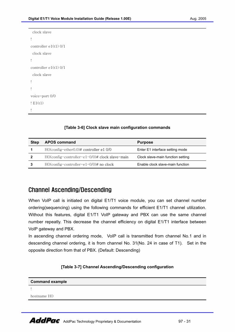
Channel Ascending/Descending
When VoIP call is initiated on digital E1/T1 voice module, you can set channel number ordering(sequencing) using the following commands for efficient E1/T1 channel utilization. Without this features, digital E1/T1 VoIP gateway and PBX can use the same channel number repeatly. This decrease the channel efficiency on digital E1/T1 interface between VoIP gateway and PBX. In ascending channel ordering mode, VoIP call is transmitted from channel No.1 and in descending channel ordering, it is from channel No. 31(No. 24 in case of T1). Set in the opposite direction from that of PBX. (Default: Descending)
[Table 3-7] Channel Ascending/Descending configuration
Command example
!
hostname HO

Digital E1/T1 Voice Module Installation Guide (Release 1.00E) Aug. 2005
AddPac Technology Proprietary & Documentation 97 - 32
!
interface ether0.0
ip address 194.168.1.2 255.255.255.0
!
! PRI controller configuration.
!
controller e1(t1) 0/0
chan-number-order ascending(descending/redom)
!
voice-port 0/0
! E1(t1)
!
[Table 3-8] Channel Ascending/Descending configuration commands
Step APOS command Purpose
1 HO(config-ether0.0)# controller e1 0/0 Enter E1 interface setting mode
2 HO(config-controller-e1-0/0)# chan-number-order <
ascending | descending |redom >
Set channel number order
Compand-type [ulaw/Alaw /au-law/ua-law]
Use “compand-type” command in voice-companding configuration. Threre are two kinds of PCM companding scheme; µ-law, the North American version and a-law, the Europian version. In most of PBX, the companding type is configurable as one of A-law or µ-law. But, some old generation PBXs only supports single companding type: the µ-law or A-law. For this kind of PBX, AddPac VoIP gateway supports the both A-law and µ-law companding type through controlling “compand-type” to PBX.
[Table 3-9] Compand type configuration
Command example
!
hostname HO
!
interface ether0.0
ip address 194.168.1.2 255.255.255.0
!
Digital E1/T1 Voice Module Installation Guide (Release 1.00E) Aug. 2005
AddPac Technology Proprietary & Documentation 97 - 33
! PRI controller configuration.
!
controller e1(t1) 0/0
!
voice-port 0/0
! E1(t1)
compand-type a-law
!
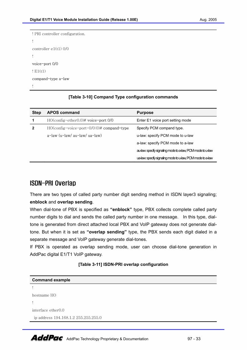
[Table 3-10] Compand Type configuration commands
Step APOS command Purpose
1 HO(config-ether0.0)# voice-port 0/0 Enter E1 voice port setting mode
2 HO(config-voice-port-0/0:0)# compand-type
a-law (u-law/ au-law/ ua-law)
Specify PCM compand type.
u-law: specify PCM mode to u-law
a-law: specify PCM mode to a-law
au-law: specify signaling mode to a-law, PCM mode to u-law
ua-law: specify signaling mode to u-law, PCM mode to a-law
ISDN-PRI Overlap
There are two types of called party number digit sending method in ISDN layer3 signaling; enblock and overlap sending. When dial-tone of PBX is specified as “enblock” type, PBX collects complete called party number digits to dial and sends the called party number in one message. In this type, dial-tone is generated from direct attached local PBX and VoIP gateway does not generate dial-tone. But when it is set as “overlap sending” type, the PBX sends each digit dialed in a separate message and VoIP gateway generate dial-tones. If PBX is operated as overlap sending mode, user can choose dial-tone generation in AddPac digital E1/T1 VoIP gateway.
[Table 3-11] ISDN-PRI overlap configuration
Command example
!
hostname HO
!
interface ether0.0
ip address 194.168.1.2 255.255.255.0
Digital E1/T1 Voice Module Installation Guide (Release 1.00E) Aug. 2005
AddPac Technology Proprietary & Documentation 97 - 34
!
! PRI controller configuration.
!
controller e1 0/0
clock-source slave
channel-group timeslots 1-31 0
!
voice-port 0/0
! E1(t1)
dial-tone-generate
!
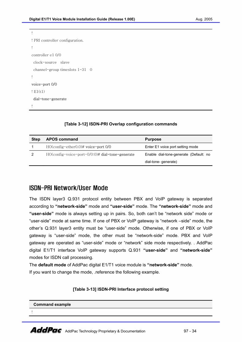
[Table 3-12] ISDN-PRI Overlap configuration commands
Step APOS command Purpose
1 HO(config-ether0.0)# voice-port 0/0 Enter E1 voice port setting mode
2 HO(config-voice-port-0/0:0)# dial-tone-generate Enable dial-tone-generate (Default: no
dial-tone- generate)
ISDN-PRI Network/User Mode
The ISDN layer3 Q.931 protocol entity between PBX and VoIP gateway is separated according to “network-side” mode and “user-side” mode. The “network-side” mode and “user-side” mode is always setting up in pairs. So, both can’t be “network side” mode or “user-side” mode at same time. If one of PBX or VoIP gateway is “network –side” mode, the other’s Q.931 layer3 entity must be “user-side” mode. Otherwise, if one of PBX or VoIP gateway is “user-side” mode, the other must be “network-side” mode. PBX and VoIP gateway are operated as “user-side” mode or “network” side mode respectively. . AddPac digital E1/T1 interface VoIP gateway supports Q.931 “user-side” and “network-side” modes for ISDN call processing. The default mode of AddPac digital E1/T1 voice module is “network-side” mode. If you want to change the mode, .reference the following example.
[Table 3-13] ISDN-PRI Interface protocol setting
Command example
!

Digital E1/T1 Voice Module Installation Guide (Release 1.00E) Aug. 2005
AddPac Technology Proprietary & Documentation 97 - 35
hostname HO
!
interface ether0.0
ip address 194.168.1.2 255.255.255.0
!
! PRI controller configuration.
!
controller e1 0/0
clock-source slave
channel-group timeslots 1-31 0
isdn protocol-emulate user
!
voice-port 0/0
! E1(t1)
!
[Table 3-14] ISDN-PRI protocol setting commands
Step APOS command Purpose
1 HO(config-ether0.0)# controller e1 0/0 Enter E1 interface setting mode
2 HO(config-controller-e1-0/0)# isdn protocol-emulate
user
Specify ISDN PRI layer3 protocol
entity mode.
ISDN-PRI Overlap-sending
When overlap-sending called party number transmission mechanism is configured in called party digital E1/T1 VoIP gateway interworking with PBX, if there is no called party number in call-setup message from VoIP gateway, PBX recognizes it as overlap sending called party number transmission mode and sends Setup-ACK layer3 message. VoIP gateway, which received Setup-ACK from called party PBX, translates digit transmitted from calling party to INFO message and sends it to PBX side. When dialing is completed, PBX sends ALERTING message and CONNECT message, and VoIP gateway sends CONNECT ACK message to called party PBX. After the procedure is completed, the channel is occupied and start the voice conversation.
(Figure 3-1) Digital E1/T1 ISDN-PRI Sending Diagram

Digital E1/T1 Voice Module Installation Guide (Release 1.00E) Aug. 2005
AddPac Technology Proprietary & Documentation 97 - 36
[Table 3-15] ISDN-PRI Overlap-Sending configuration
Command example
!
hostname HO
!
interface ether0.0
ip address 194.168.1.2 255.255.255.0
!
! PRI controller configuration.
!
controller e1 0/0
clock-source slave
channel-group timeslots 1-31 0
isdn overlap-sending
!
voice-port 0/0
! E1(t1)
!
Digital E1/T1 Voice Module Installation Guide (Release 1.00E) Aug. 2005
AddPac Technology Proprietary & Documentation 97 - 37
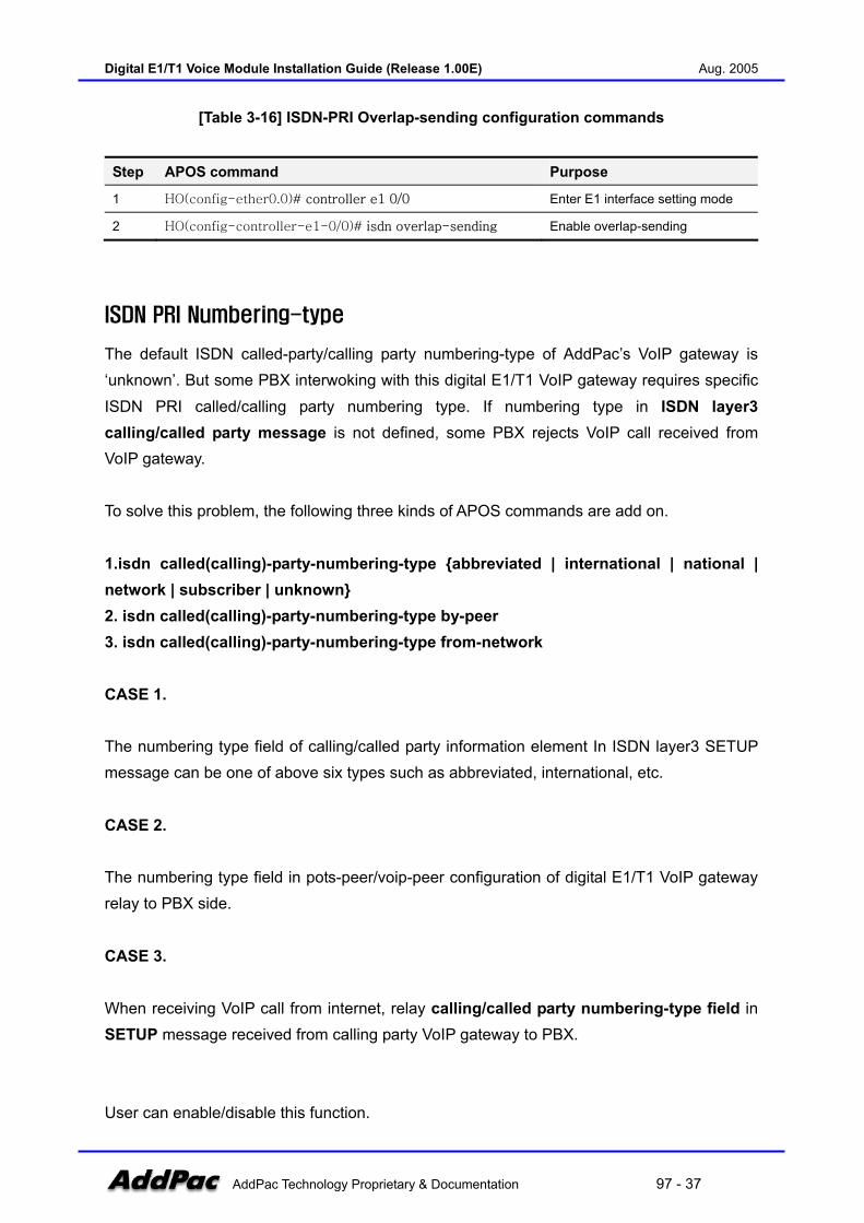
[Table 3-16] ISDN-PRI Overlap-sending configuration commands
Step APOS command Purpose
1 HO(config-ether0.0)# controller e1 0/0 Enter E1 interface setting mode
2 HO(config-controller-e1-0/0)# isdn overlap-sending Enable overlap-sending
ISDN PRI Numbering-type
The default ISDN called-party/calling party numbering-type of AddPac’s VoIP gateway is ‘unknown’. But some PBX interwoking with this digital E1/T1 VoIP gateway requires specific ISDN PRI called/calling party numbering type. If numbering type in ISDN layer3 calling/called party message is not defined, some PBX rejects VoIP call received from VoIP gateway. To solve this problem, the following three kinds of APOS commands are add on. 1.isdn called(calling)-party-numbering-type abbreviated | international | national | network | subscriber | unknown 2. isdn called(calling)-party-numbering-type by-peer 3. isdn called(calling)-party-numbering-type from-network CASE 1. The numbering type field of calling/called party information element In ISDN layer3 SETUP message can be one of above six types such as abbreviated, international, etc. CASE 2. The numbering type field in pots-peer/voip-peer configuration of digital E1/T1 VoIP gateway relay to PBX side. CASE 3. When receiving VoIP call from internet, relay calling/called party numbering-type field in SETUP message received from calling party VoIP gateway to PBX. User can enable/disable this function.

Digital E1/T1 Voice Module Installation Guide (Release 1.00E) Aug. 2005
AddPac Technology Proprietary & Documentation 97 - 38
IPAddPac
VoIP GatewayAddPac
VoIP Gateway
controller e1 0/0isdn called-party-numbering-type from-networkisdn calling-party-numbering-type from-network
PBX
AnalogPhone
AnalogPhone
cd = nationalcg = network
Setup
cd = nationalcg = network
Setup
(Figure 3-2) ISDN-PRI Numbering-type Diagram
[Table 3-17] ISDN-PRI Numbering-type configuration
Command example
!
hostname HO
!
interface ether0.0
ip address 194.168.1.2 255.255.255.0
!
! PRI controller configuration.
!
controller e1 0/0
clock-source slave
channel-group timeslots 1-31 0
isdn called-party-numbering-type from-network
isdn calling-party-numbering-type from-network
!
voice-port 0/0
! E1(t1)
!
[Table 3-18] ISDN-PRI Numbering-type configuration commands
Digital E1/T1 Voice Module Installation Guide (Release 1.00E) Aug. 2005
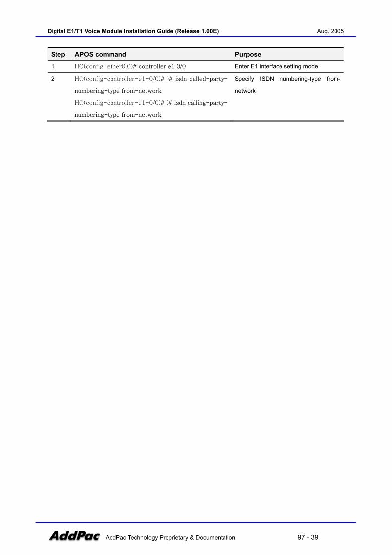
AddPac Technology Proprietary & Documentation 97 - 39
Step APOS command Purpose
1 HO(config-ether0.0)# controller e1 0/0 Enter E1 interface setting mode
2 HO(config-controller-e1-0/0)# )# isdn called-party-
numbering-type from-network
HO(config-controller-e1-0/0)# )# isdn calling-party-
numbering-type from-network
Specify ISDN numbering-type from-
network

Digital E1/T1 Voice Module Installation Guide (Release 1.00E) Aug. 2005
AddPac Technology Proprietary & Documentation 97 - 40
R2-MFC Overlap
In R2 signaling section, digit transmission should use the overlap type to receive digit number due to the signaling characteristic. But, PBX or VoIP gateway can collect digit number in either enblock or overlap type before passing through R2 interface. After calling party (PBX internal line user) press the access code, PBX generates dial-tone when PBX is operated as enblock type, VoIP gateway generates dial-tone when PBX is operated as overlap type. In AddPac digital E1/T1 VoIP gateway, dial-tone is generated selectively to calling party (PBX internal line user) when PBX is operated as overlap type.
[Table 3-19] R2-MFC Overlap configuration
Displays configuration instruction
!
hostname HO
!
interface ether0.0
ip address 194.168.1.2 255.255.255.0
!
! R2 Controller configuration.
!
controller e1 0/0
signaling-type r2
channel-group timeslots 1-31 0
!
voice-port 0/0
dial-tone-generate
!
[Table 3-20] R2-MFC Overlap configuration commands
Step APOS command Purpose
1 HO(config-ether0.0)# voice-port 0/0 Enter E1 voice port setting mode
2 HO(config-voice-port-0/0:0)# dial-tone-generate Enable dial-tone-generate (Default: no
dial-tone- generate)
Digital E1/T1 Voice Module Installation Guide (Release 1.00E) Aug. 2005
AddPac Technology Proprietary & Documentation 97 - 41
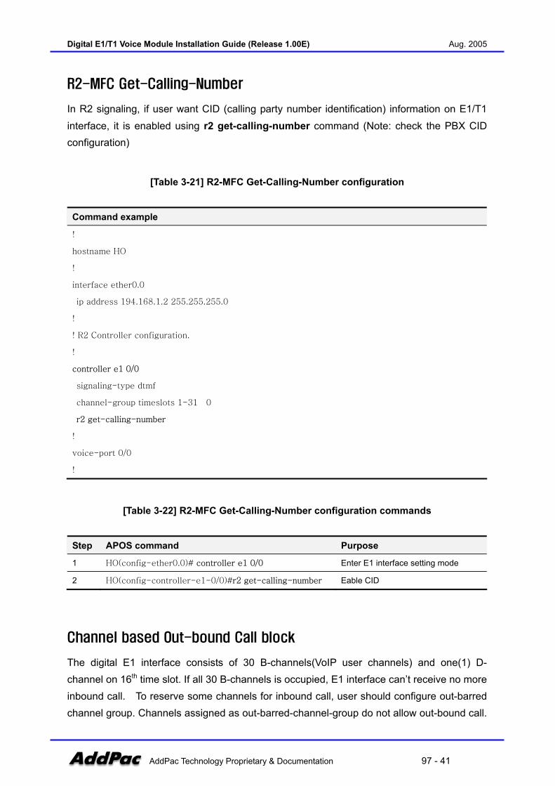
R2-MFC Get-Calling-Number
In R2 signaling, if user want CID (calling party number identification) information on E1/T1 interface, it is enabled using r2 get-calling-number command (Note: check the PBX CID configuration)
[Table 3-21] R2-MFC Get-Calling-Number configuration
Command example
!
hostname HO
!
interface ether0.0
ip address 194.168.1.2 255.255.255.0
!
! R2 Controller configuration.
!
controller e1 0/0
signaling-type dtmf
channel-group timeslots 1-31 0
r2 get-calling-number
!
voice-port 0/0
!
[Table 3-22] R2-MFC Get-Calling-Number configuration commands
Step APOS command Purpose
1 HO(config-ether0.0)# controller e1 0/0 Enter E1 interface setting mode
2 HO(config-controller-e1-0/0)#r2 get-calling-number Eable CID
Channel based Out-bound Call block
The digital E1 interface consists of 30 B-channels(VoIP user channels) and one(1) D-channel on 16th time slot. If all 30 B-channels is occupied, E1 interface can’t receive no more inbound call. To reserve some channels for inbound call, user should configure out-barred channel group. Channels assigned as out-barred-channel-group do not allow out-bound call.
Digital E1/T1 Voice Module Installation Guide (Release 1.00E) Aug. 2005
AddPac Technology Proprietary & Documentation 97 - 42
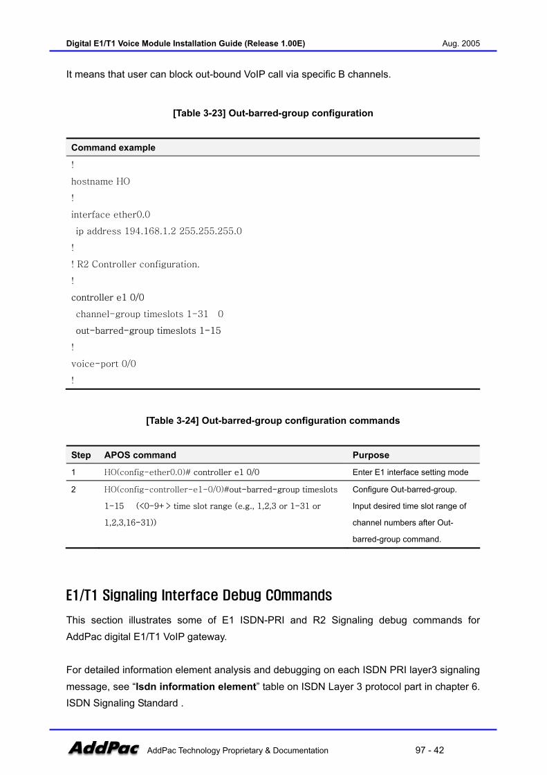
It means that user can block out-bound VoIP call via specific B channels.
[Table 3-23] Out-barred-group configuration
Command example
!
hostname HO
!
interface ether0.0
ip address 194.168.1.2 255.255.255.0
!
! R2 Controller configuration.
!
controller e1 0/0
channel-group timeslots 1-31 0
out-barred-group timeslots 1-15
!
voice-port 0/0
!
[Table 3-24] Out-barred-group configuration commands
Step APOS command Purpose
1 HO(config-ether0.0)# controller e1 0/0 Enter E1 interface setting mode
2 HO(config-controller-e1-0/0)#out-barred-group timeslots
1-15 (<0-9+> time slot range (e.g., 1,2,3 or 1-31 or
1,2,3,16-31))
Configure Out-barred-group.
Input desired time slot range of
channel numbers after Out-
barred-group command.
E1/T1 Signaling Interface Debug COmmands
This section illustrates some of E1 ISDN-PRI and R2 Signaling debug commands for AddPac digital E1/T1 VoIP gateway. For detailed information element analysis and debugging on each ISDN PRI layer3 signaling message, see “Isdn information element” table on ISDN Layer 3 protocol part in chapter 6. ISDN Signaling Standard .
Digital E1/T1 Voice Module Installation Guide (Release 1.00E) Aug. 2005
AddPac Technology Proprietary & Documentation 97 - 43
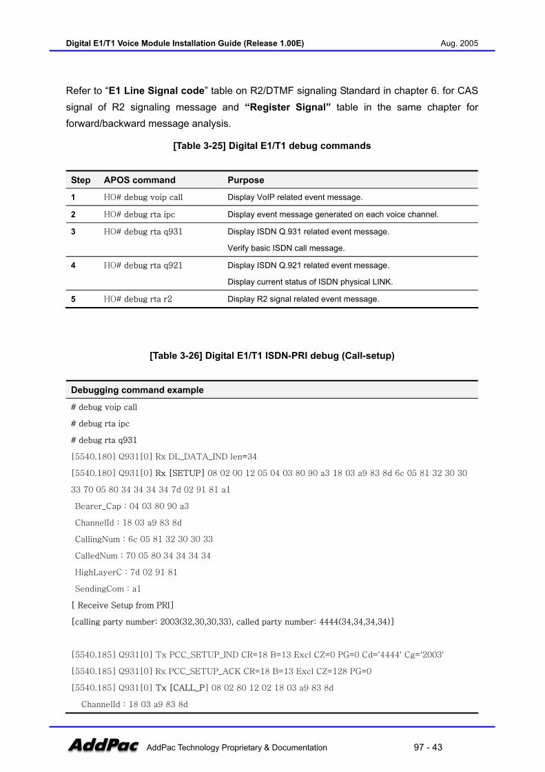
Refer to “E1 Line Signal code” table on R2/DTMF signaling Standard in chapter 6. for CAS signal of R2 signaling message and “Register Signal” table in the same chapter for forward/backward message analysis.
[Table 3-25] Digital E1/T1 debug commands
Step APOS command Purpose
1 HO# debug voip call Display VoIP related event message.
2 HO# debug rta ipc Display event message generated on each voice channel.
3 HO# debug rta q931 Display ISDN Q.931 related event message.
Verify basic ISDN call message.
4 HO# debug rta q921 Display ISDN Q.921 related event message.
Display current status of ISDN physical LINK.
5 HO# debug rta r2 Display R2 signal related event message.
[Table 3-26] Digital E1/T1 ISDN-PRI debug (Call-setup)
Debugging command example
# debug voip call
# debug rta ipc
# debug rta q931
[5540.180] Q931[0] Rx DL_DATA_IND len=34
[5540.180] Q931[0] Rx [SETUP] 08 02 00 12 05 04 03 80 90 a3 18 03 a9 83 8d 6c 05 81 32 30 30
33 70 05 80 34 34 34 34 7d 02 91 81 a1
Bearer_Cap : 04 03 80 90 a3
ChannelId : 18 03 a9 83 8d
CallingNum : 6c 05 81 32 30 30 33
CalledNum : 70 05 80 34 34 34 34
HighLayerC : 7d 02 91 81
SendingCom : a1
[ Receive Setup from PRI]
[calling party number: 2003(32,30,30,33), called party number: 4444(34,34,34,34)]
[5540.185] Q931[0] Tx PCC_SETUP_IND CR=18 B=13 Excl CZ=0 PG=0 Cd='4444' Cg='2003'
[5540.185] Q931[0] Rx PCC_SETUP_ACK CR=18 B=13 Excl CZ=128 PG=0
[5540.185] Q931[0] Tx [CALL_P] 08 02 80 12 02 18 03 a9 83 8d
ChannelId : 18 03 a9 83 8d
Digital E1/T1 Voice Module Installation Guide (Release 1.00E) Aug. 2005
AddPac Technology Proprietary & Documentation 97 - 44
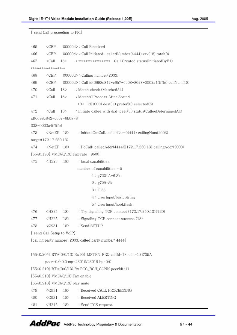
[ send Call proceeding to PRI]
465 <CEP 00000d> : Call Received
466 <CEP 00000d> : Call Initiated : calledNumber(4444) crv(18) total(0)
467 <Call 18> : ****************** Call Created status(InitiatedByE1)
*******************
468 <CEP 00000d> : Calling number(2003)
469 <CEP 00000d> : Call id(0698c842-c6b7-6b08-8028-0002a4fffffe) callNum(18)
470 <Call 18> : Match check (MatchedAll)
471 <Call 18> : MatchAllProcess After Sorted
<0> id(1000) dest(T) prefer(0) selected(8)
472 <Call 18> : Initiate callee with dial-peer(T) status(CalleeDeterminedAll)
id(0698c842-c6b7-6b08-8
028-0002a4fffffe)
473 <NetEP 18> : InitiateOutCall: calledNum(4444) callingNum(2003)
target(172.17.250.13)
474 <NetEP 18> : DoCall: calledAddr([email protected]) callingAddr(2003)
[5540.190] VM(0/0/13) Fax rate 9600
475 <H323 18> : local capabilities.
number of capabilities = 5
1 : g7231A-6.3k
2 : g729-8k
3 : T.38
4 : UserInput/basicString
5 : UserInput/hookflash
476 <H225 18> : Try signaling TCP connect (172.17.250.13:1720)
477 <H225 18> : Signaling TCP connect success (18)
478 <Q931 18> : Send SETUP
[ send Call Setup to VoIP]
[calling party number: 2003, called party number: 4444]
[5540.205] RTA(0/0/13) Rx RS_LISTEN_REQ callId=18 ssId=1 G729A
peer=0.0.0.0 mp=23018/23019 hp=0/0
[5540.210] RTA(0/0/13) Rx PCC_BCH_CONN peerId(-1)
[5540.210] VM(0/0/13) Fax enable
[5540.210] VM(0/0/13) play mute
479 <Q931 18> : Received CALL PROCEEDING
480 <Q931 18> : Received ALERTING
481 <H245 18> : Send TCS request.
Digital E1/T1 Voice Module Installation Guide (Release 1.00E) Aug. 2005
AddPac Technology Proprietary & Documentation 97 - 45
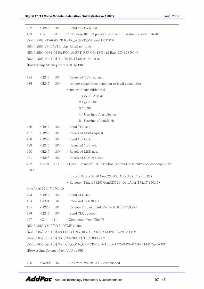
482 <H245 18> : Send MSD request.
483 <Call 18> : Alert from(ffffffff) pseudo(0) inband(0) status(CalleeInitiated)
[5540.250] RTA(0/0/13) Rx CC_ALERT_RSP peerId(0/0/0)
[5540.250] VM(0/0/13) play RingBack tone
[5540.250] Q931[0] Rx PCC_ALERT_RSP CR=18 B=13 Excl CZ=128 PG=0
[5540.250] Q931[0] Tx [ALERT] 08 02 80 12 01
[Forwarding Alerting from VoIP to PRI]
484 <H245 18> : Received TCS request.
485 <H245 18> : remote capabilities matching to local capabilities.
number of capabilities = 5
1 : g7231A-6.3k
2 : g729-8k
3 : T.38
4 : UserInput/basicString
5 : UserInput/hookflash
486 <H245 18> : Send TCS ack.
487 <H245 18> : Received MSD request.
488 <H245 18> : Send MSD ack.
489 <H245 18> : Received TCS ack..
490 <H245 18> : Received MSD ack.
491 <H245 18> : Received OLC request.
492 <Chan 18> : Open - number(101) direction(receive) session(voice) codec(g7231A-
6.3k)
- Local : Data(23018) Cont(23019) Addr(172.17.203.101)
- Remote : Data(23328) Cont(23329) DataAddr(172.17.250.13)
ContAddr(172.17.250.13)
493 <H245 18> : Send OLC ack.
494 <Q931 18> : Received CONNECT
495 <H225 18> : Remote Endpoint (AddPac VoIP,8.10,97,0,22)
496 <H245 18> : Send OLC request.
497 <Call 18> : Connected from(ffffffff)
[5543.985] VM(0/0/13) DTMF enable
[5543.985] Q931[0] Rx PCC_CONN_REQ CR=18 B=13 Excl CZ=128 PG=0
[5543.985] Q931[0] Tx [CONNECT] 08 02 80 12 07
[5543.985] Q931[0] Tx PCC_CONN_CNF CR=18 B=13 Excl CZ=0 PG=0 Cd='4444' Cg='2003'
[Forwarding Connect from VoIP to PRI]
498 <NetEP 18> : Call with mskim-2003 established
Digital E1/T1 Voice Module Installation Guide (Release 1.00E) Aug. 2005
AddPac Technology Proprietary & Documentation 97 - 46
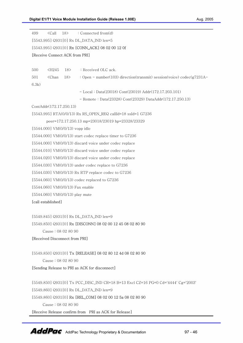
499 <Call 18> : Connected from(d)
[5543.995] Q931[0] Rx DL_DATA_IND len=5
[5543.995] Q931[0] Rx [CONN_ACK] 08 02 00 12 0f
[Receive Connect ACK from PRI]
500 <H245 18> : Received OLC ack.
501 <Chan 18> : Open - number(103) direction(transmit) session(voice) codec(g7231A-
6.3k)
- Local : Data(23018) Cont(23019) Addr(172.17.203.101)
- Remote : Data(23328) Cont(23329) DataAddr(172.17.250.13)
ContAddr(172.17.250.13)
[5543.995] RTA(0/0/13) Rx RS_OPEN_REQ callId=18 ssId=1 G7236
peer=172.17.250.13 mp=23018/23019 hp=23328/23329
[5544.000] VM(0/0/13) vopp idle
[5544.000] VM(0/0/13) start codec replace timer to G7236
[5544.000] VM(0/0/13) discard voice under codec replace
[5544.010] VM(0/0/13) discard voice under codec replace
[5544.020] VM(0/0/13) discard voice under codec replace
[5544.030] VM(0/0/13) under codec replace to G7236
[5544.030] VM(0/0/13) Rx RTP replace codec to G7236
[5544.060] VM(0/0/13) codec replaced to G7236
[5544.060] VM(0/0/13) Fax enable
[5544.060] VM(0/0/13) play mute
[call established]
[5549.845] Q931[0] Rx DL_DATA_IND len=9
[5549.850] Q931[0] Rx [DISCONN] 08 02 00 12 45 08 02 80 90
Cause : 08 02 80 90
[Received Disconnect from PRI]
[5549.850] Q931[0] Tx [RELEASE] 08 02 80 12 4d 08 02 80 90
Cause : 08 02 80 90
[Sending Release to PRI as ACK for disconnect]
[5549.850] Q931[0] Tx PCC_DISC_IND CR=18 B=13 Excl CZ=16 PG=0 Cd='4444' Cg='2003'
[5549.860] Q931[0] Rx DL_DATA_IND len=9
[5549.860] Q931[0] Rx [REL_COM] 08 02 00 12 5a 08 02 80 90
Cause : 08 02 80 90
[Receive Release confirm from PRI as ACK for Release]

Digital E1/T1 Voice Module Installation Guide (Release 1.00E) Aug. 2005
AddPac Technology Proprietary & Documentation 97 - 47
[5549.860] Q931[0] Tx PCC_DISC_CNF CR=18 B=13 Excl CZ=16 PG=0 Cd='4444' Cg='2003'
502 <CEP 00000d> : Disconnected(16)
[5549.860] RTA(0/0/13) Rx PCC_BCH_DISC peerId(0/0/0)
[5549.860] VM(0/0/13) vopp idle
[5549.860] VM(0/0/13) Rx BchDISC close sep in force
[5549.865] VM(0/0/13) RTP session close force
[5549.865] RTA(0/0/13) close Media socket
[5549.865] RTA(0/0/13) close RTCP socket
503 <Call 18> : Terminated from(d) this(Local:CallClear) before(NULL) forced(0)
[5549.865] RTA(0/0/13) Rx RS_CLOSE_REQ callId=18 ssId=1 dir=reve
[5549.865] RTA(0/0/13) no session, ignore
504 <Chan 18> : Close - number(101) direction(receive)
[5549.865] RTA(0/0/13) Rx RS_CLOSE_REQ callId=18 ssId=1 dir=forw
[5549.865] RTA(0/0/13) no session, ignore
505 <Chan 18> : Close - number(103) direction(transmit)
506 <Q931 18> : Send RELEASE COMPLETE
[Sending Release complete to VoIP]
507 <NetEP 18> : Call TO <mskim-2003> terminated reason(Local:CallClear)
[Table 3-27] Digital E1/T1 R2-MFC debug (Call-setup)
R2 debugging command example (call-setup)
# debug voip call
# debug rta ipc
# debug rta r2
[103.285] R2(0/0/31) Rx CAS A=0 B=0
[received channel seizure confirmation from R2]
[103.285] R2(0/0/31) Tx CAS A=1 B=1
[Sending Rchannel seizure comfirmation to R2]
[103.285] VM(0/0/31) Tx OFFHOOK_IND
1 <CEP 00001f> : Call Received
2 <CEP 00001f> : Call Initiated : calledNumber() crv(0) total(0)
3 <Call 1> : ****************** Call Created status(InitiatedByE1)
*******************

Digital E1/T1 Voice Module Installation Guide (Release 1.00E) Aug. 2005
AddPac Technology Proprietary & Documentation 97 - 48
4 <CEP 00001f> : Calling number()
5 <CEP 00001f> : Call id(75a0c842-e098-29c2-8001-0002a4fffffe) callNum(1)
[103.290] VM(0/0/31) play mute
[103.335] R2(0/0/31) Rx FW I-4: Digit 4
[103.335] VM(0/0/31) Tx DIGIT_IND '4'
[received digit 4 from R2]
[103.335] R2(0/0/31) Tx BW A1: Send Next Digit
[send next digit request to R2]
6 <Call 1> : Digit(4) at InitiatedByE1
7 <Call 1> : MatchedAll
[103.515] R2(0/0/31) MFC signal OFF, mute ON
[103.515] VM(0/0/31) play mute
[103.615] R2(0/0/31) mute timeout
[103.725] R2(0/0/31) Rx FW I-4: Digit 4
[103.725] VM(0/0/31) Tx DIGIT_IND '4'
[received digit 4 from R2]
[103.725] R2(0/0/31) Tx BW A1: Send Next Digit
[send next digit request to R2]
8 <Call 1> : Digit(4) at CalleeDeterminedWaitDigit
9 <Call 1> : MatchedAll
[103.905] R2(0/0/31) MFC signal OFF, mute ON
[103.905] VM(0/0/31) play mute
[104.005] R2(0/0/31) mute timeout
[104.115] R2(0/0/31) Rx FW I-4: Digit 4
[104.115] VM(0/0/31) Tx DIGIT_IND '4'
[received digit 4 from R2]
[104.115] R2(0/0/31) Tx BW A1: Send Next Digit
[send next digit request to R2]
10 <Call 1> : Digit(4) at CalleeDeterminedWaitDigit
11 <Call 1> : MatchedAll
[104.295] R2(0/0/31) MFC signal OFF, mute ON
[104.295] VM(0/0/31) play mute
[104.395] R2(0/0/31) mute timeout

Digital E1/T1 Voice Module Installation Guide (Release 1.00E) Aug. 2005
AddPac Technology Proprietary & Documentation 97 - 49
[104.505] R2(0/0/31) Rx FW I-4: Digit 4
[104.505] VM(0/0/31) Tx DIGIT_IND '4'
[received digit 4 from R2]
[104.505] R2(0/0/31) Tx BW A1: Send Next Digit
[send next digit request to R2]
12 <Call 1> : Digit(4) at CalleeDeterminedWaitDigit
13 <Call 1> : MatchedAll
[104.685] R2(0/0/31) MFC signal OFF, mute ON
[104.685] VM(0/0/31) play mute
[104.785] R2(0/0/31) mute timeout
[104.895] R2(0/0/31) Rx FW I-15: Sending Comp
[received sending complete from R2]
[104.895] VM(0/0/31) Tx DIGIT_IND '#'
14 <Call 1> : Digit(#) at CalleeDeterminedWaitDigit
[104.895] RTA(0/0/31) Rx RCC_ADDR_CMP peerId(0/0/0)
[104.895] R2(0/0/31) Tx BW A3: Address Comp, Changeover Group-B Rx
[sending Address complete change over to reception of Group B Signal to R2]
15 <Call 1> : MatchAllProcess After Sorted
<0> id(1000) dest(T) prefer(0) selected(0)
16 <Call 1> : Initiate callee with dial-peer(T) status(CalleeDeterminedAll)
id(75a0c842-e098-29c2-8001-0002a4fffffe)
17 <NetEP 1> : InitiateOutCall: calledNum(4444) callingNum() target(172.17.250.13)
18 <NetEP 1> : DoCall: calledAddr([email protected]) callingAddr()
[104.895] VM(0/0/31) Fax rate 9600
19 <H323 1> : local capabilities.
number of capabilities = 5
1 : g7231A-6.3k
2 : g729-8k
3 : T.38
4 : UserInput/basicString
5 : UserInput/hookflash
20 <H225 1> : Try signaling TCP connect (172.17.250.13:1720)
21 <H225 1> : Signaling TCP connect success (1)
22 <Q931 1> : Send SETUP
[sending Setup to VoIP]
Digital E1/T1 Voice Module Installation Guide (Release 1.00E) Aug. 2005
AddPac Technology Proprietary & Documentation 97 - 50
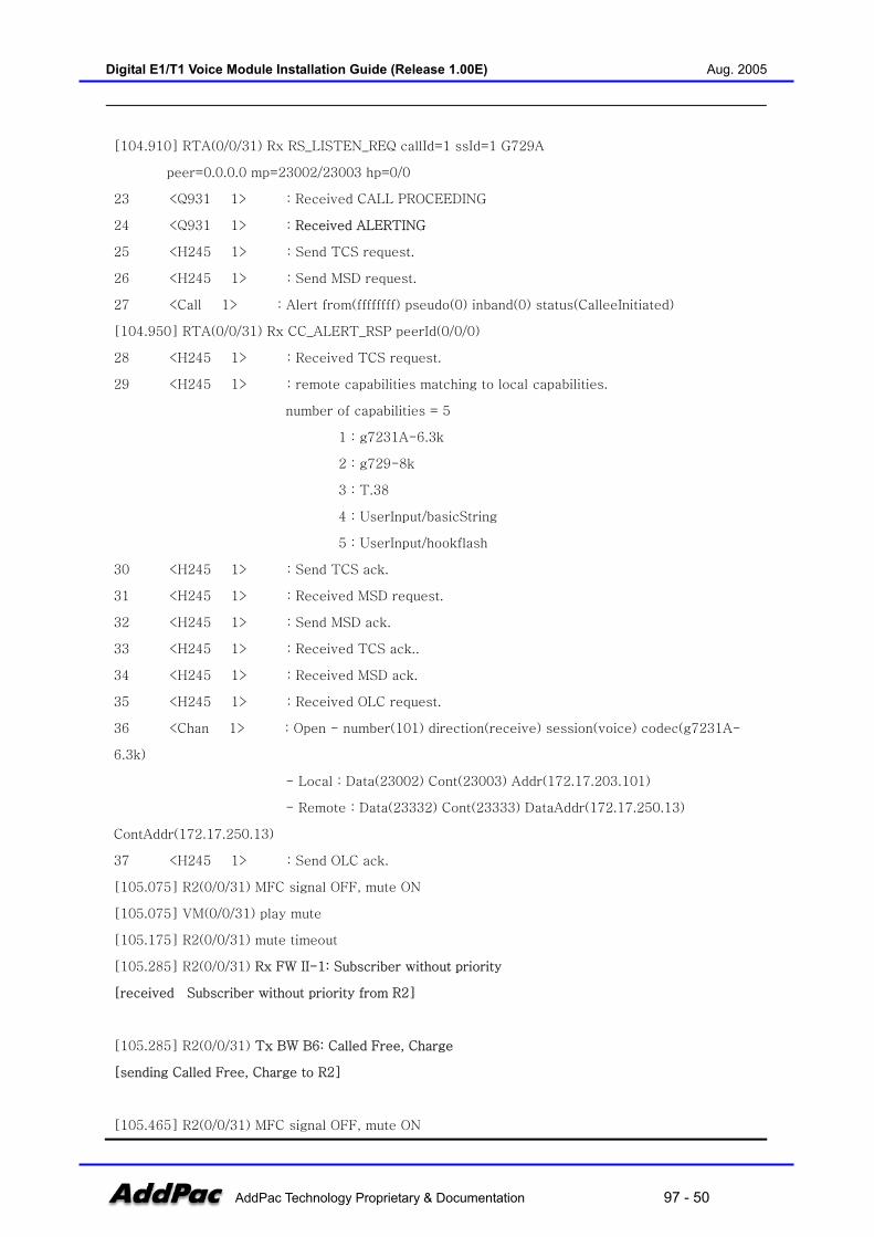
[104.910] RTA(0/0/31) Rx RS_LISTEN_REQ callId=1 ssId=1 G729A
peer=0.0.0.0 mp=23002/23003 hp=0/0
23 <Q931 1> : Received CALL PROCEEDING
24 <Q931 1> : Received ALERTING
25 <H245 1> : Send TCS request.
26 <H245 1> : Send MSD request.
27 <Call 1> : Alert from(ffffffff) pseudo(0) inband(0) status(CalleeInitiated)
[104.950] RTA(0/0/31) Rx CC_ALERT_RSP peerId(0/0/0)
28 <H245 1> : Received TCS request.
29 <H245 1> : remote capabilities matching to local capabilities.
number of capabilities = 5
1 : g7231A-6.3k
2 : g729-8k
3 : T.38
4 : UserInput/basicString
5 : UserInput/hookflash
30 <H245 1> : Send TCS ack.
31 <H245 1> : Received MSD request.
32 <H245 1> : Send MSD ack.
33 <H245 1> : Received TCS ack..
34 <H245 1> : Received MSD ack.
35 <H245 1> : Received OLC request.
36 <Chan 1> : Open - number(101) direction(receive) session(voice) codec(g7231A-
6.3k)
- Local : Data(23002) Cont(23003) Addr(172.17.203.101)
- Remote : Data(23332) Cont(23333) DataAddr(172.17.250.13)
ContAddr(172.17.250.13)
37 <H245 1> : Send OLC ack.
[105.075] R2(0/0/31) MFC signal OFF, mute ON
[105.075] VM(0/0/31) play mute
[105.175] R2(0/0/31) mute timeout
[105.285] R2(0/0/31) Rx FW II-1: Subscriber without priority
[received Subscriber without priority from R2]
[105.285] R2(0/0/31) Tx BW B6: Called Free, Charge
[sending Called Free, Charge to R2]
[105.465] R2(0/0/31) MFC signal OFF, mute ON

Digital E1/T1 Voice Module Installation Guide (Release 1.00E) Aug. 2005
AddPac Technology Proprietary & Documentation 97 - 51
[105.465] VM(0/0/31) play mute
[105.565] R2(0/0/31) mute timeout
[105.565] VM(0/0/31) vopp idle
[105.565] VM(0/0/31) start codec replace timer to G729A
[105.575] VM(0/0/31) discard voice under codec replace
[105.625] VM(0/0/31) codec replaced to G729A
[105.625] VM(0/0/31) Fax enable
[105.625] VM(0/0/31) play mute
[105.625] VM(0/0/31) play RingBack tone
[play Ringback tone to R2]
38 <Q931 1> : Received CONNECT
[received CONNECT from VoIP]
39 <H225 1> : Remote Endpoint (AddPac VoIP,8.10,97,0,22)
40 <H245 1> : Send OLC request.
41 <Call 1> : Connected from(ffffffff)
[121.430] VM(0/0/31) DTMF enable
[121.430] RTA(0/0/31) Rx CC_CONNECT_RSP peerId(0/0/0)
[121.430] VM(0/0/31) Fax enable
[121.430] VM(0/0/31) play mute
[121.430] R2(0/0/31) Tx CAS A=0 B=1
[Sending CONNECT to R2]
42 <NetEP 1> : Call with mskim-2003 established
43 <H245 1> : Received OLC ack.
44 <Chan 1> : Open - number(103) direction(transmit) session(voice) codec(g7231A-
6.3k)
- Local : Data(23002) Cont(23003) Addr(172.17.203.101)
- Remote : Data(23332) Cont(23333) DataAddr(172.17.250.13)
ContAddr(172.17.250.13)
[121.440] RTA(0/0/31) Rx RS_OPEN_REQ callId=1 ssId=1 G7236
peer=172.17.250.13 mp=23002/23003 hp=23332/23333
[121.440] VM(0/0/31) vopp idle
[121.440] VM(0/0/31) start codec replace timer to G7236
[121.450] VM(0/0/31) discard voice under codec replace
[121.460] VM(0/0/31) discard voice under codec replace
[121.470] VM(0/0/31) discard voice under codec replace
[121.475] VM(0/0/31) under codec replace to G7236
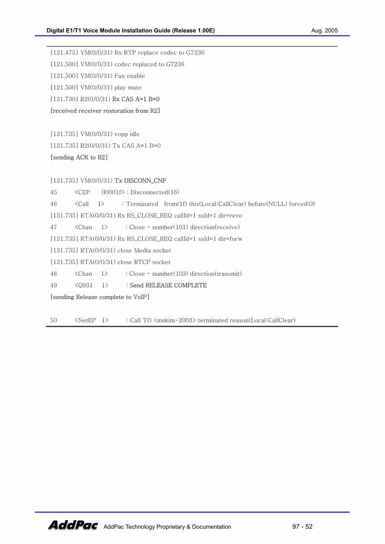
Digital E1/T1 Voice Module Installation Guide (Release 1.00E) Aug. 2005
AddPac Technology Proprietary & Documentation 97 - 52
[121.475] VM(0/0/31) Rx RTP replace codec to G7236
[121.500] VM(0/0/31) codec replaced to G7236
[121.500] VM(0/0/31) Fax enable
[121.500] VM(0/0/31) play mute
[131.730] R2(0/0/31) Rx CAS A=1 B=0
[received receiver restoration from R2]
[131.735] VM(0/0/31) vopp idle
[131.735] R2(0/0/31) Tx CAS A=1 B=0
[sending ACK to R2]
[131.735] VM(0/0/31) Tx DISCONN_CNF
45 <CEP 00001f> : Disconnected(16)
46 <Call 1> : Terminated from(1f) this(Local:CallClear) before(NULL) forced(0)
[131.735] RTA(0/0/31) Rx RS_CLOSE_REQ callId=1 ssId=1 dir=reve
47 <Chan 1> : Close - number(101) direction(receive)
[131.735] RTA(0/0/31) Rx RS_CLOSE_REQ callId=1 ssId=1 dir=forw
[131.735] RTA(0/0/31) close Media socket
[131.735] RTA(0/0/31) close RTCP socket
48 <Chan 1> : Close - number(103) direction(transmit)
49 <Q931 1> : Send RELEASE COMPLETE
[sending Release complete to VoIP]
50 <NetEP 1> : Call TO <mskim-2003> terminated reason(Local:CallClear)

Digital E1/T1 Voice Module Installation Guide (Release 1.00E) Aug. 2005
AddPac Technology Proprietary & Documentation 97 - 53
Chapter 4. APOS Command Configuration
ISDN-PRI Signaling
WAN(IP Network)
Analog Phone
Router
AddPacVoIP Gateway(Head Office)PBX
Access Code : 8Signaling Type : ISDNClock : MasterNo. of Channels : 30 or 24Compand Type : U LawProtocol : User
Access Code (E.164) : 99Signaling Type : ISDNClock : SlaveNo. of Channels : 30 or 24Compand Type : A-LawProtocol : NetworkVoice Port 0/0IP Address : 192.168.1.1
Digital E1 or T1
Setting ISDN-PRI Command for Digital E1 or T1
(Figure 4-1) Network Diagram for ISDN-PRI setup
To support old generation PBX’s digital E1/T1signaling type, AddPac digital E1/T1 VoIP gateway provides both ISDN-PRI and R2 signaling type. Each signaling type of digital E1/T1 VoIP gateway is configurable by software without hardware intervention such as DIP switch, jumper via CLI(command line interface) type APOS command parameter configuration procedure. This chapter shows the ISDN-PRI command configuration example for digital E1/T1 VoIP interface.
[Table 4-1] Digital E1/T1 ISDN-PRI configuration
Digital E1/T1 ISDN-PRI command example
!
hostname HO
!
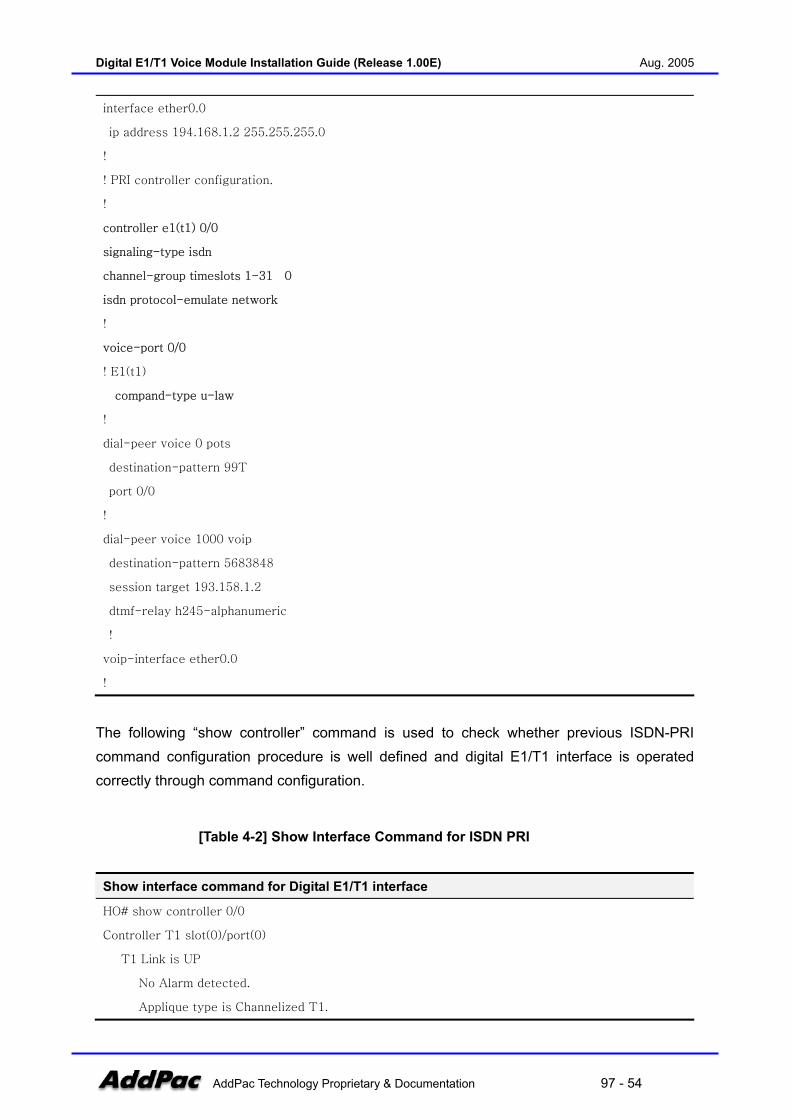
Digital E1/T1 Voice Module Installation Guide (Release 1.00E) Aug. 2005
AddPac Technology Proprietary & Documentation 97 - 54
interface ether0.0
ip address 194.168.1.2 255.255.255.0
!
! PRI controller configuration.
!
controller e1(t1) 0/0
signaling-type isdn
channel-group timeslots 1-31 0
isdn protocol-emulate network
!
voice-port 0/0
! E1(t1)
compand-type u-law
!
dial-peer voice 0 pots
destination-pattern 99T
port 0/0
!
dial-peer voice 1000 voip
destination-pattern 5683848
session target 193.158.1.2
dtmf-relay h245-alphanumeric
!
voip-interface ether0.0
!
The following “show controller” command is used to check whether previous ISDN-PRI command configuration procedure is well defined and digital E1/T1 interface is operated correctly through command configuration.
[Table 4-2] Show Interface Command for ISDN PRI
Show interface command for Digital E1/T1 interface
HO# show controller 0/0
Controller T1 slot(0)/port(0)
T1 Link is UP
No Alarm detected.
Applique type is Channelized T1.

Digital E1/T1 Voice Module Installation Guide (Release 1.00E) Aug. 2005
AddPac Technology Proprietary & Documentation 97 - 55
Framing is SF, Line Code is AMI, Cable Length is Short 110.
Signaling type is ISDN PRI.
0 Line Code Violations, 0 Framing Bit Errors
0 Out Of Frame Errors, 0 Bit Errors
6 Frames Received, 6 Frames Transmitted
signaling type = isdn
clock source = master
channel group 0 = 1-24
1 2 3
allocated timeslots = YYYYYYYYYYYYYYYYYYYYYYYNNNNNNNN
outgoing barred channel group =
channel order = descending
b-channel negotiation = exclusive
overlap receiving = enabled
protocol side = user
R2 get calling number = disabled
ISDN virtual connect = disabled
T1 cable length = short 110
T1 framing = sf
T1 line code = ami
T1 CAS type = immediate
ISDN Layer 2 is UP
ISDN Values
ISDN Layer 2 values
k = 7
N200 = 3
N201 = 260
T200 = 1 seconds
T203 = 10 seconds
ISDN Layer 3 values
T301 = 180 seconds
T302 = 15 seconds
T303 = 4 seconds
T305 = 30 seconds
T306 = 30 seconds
T308 = 4 seconds
T310 = 10 seconds
T313 = 4 seconds
T316 = 120 seconds

Digital E1/T1 Voice Module Installation Guide (Release 1.00E) Aug. 2005
AddPac Technology Proprietary & Documentation 97 - 56
T309 = 90 seconds
N303 = 1
[Table 4-3] Digital E1/T1 configuration commands
Step APOS command Purpose
1 HO(config-ether0.0)# controller e1 0/0 Enter E1 interface setting mode
2 HO(config-controller-e1-0/0)#signaling-type isdn Specify signaling type
3 HO(config-controller-e1-0/0)#channel-group timeslots
1-31 0
Specify channel group (Use all the 30
channels)
4 HO(config-ether0.0)# isdn protocol-emulate Network Specifiy “network-side” mode
5 HO(config-ether0.0)# voice-port 0/0 Start setting of voice-port 0/0.
6 HO(config-voice-port-0/0)# compand-type u-law Specify compand type configuration
(Note that this command is under
voice-port CLI command tree)
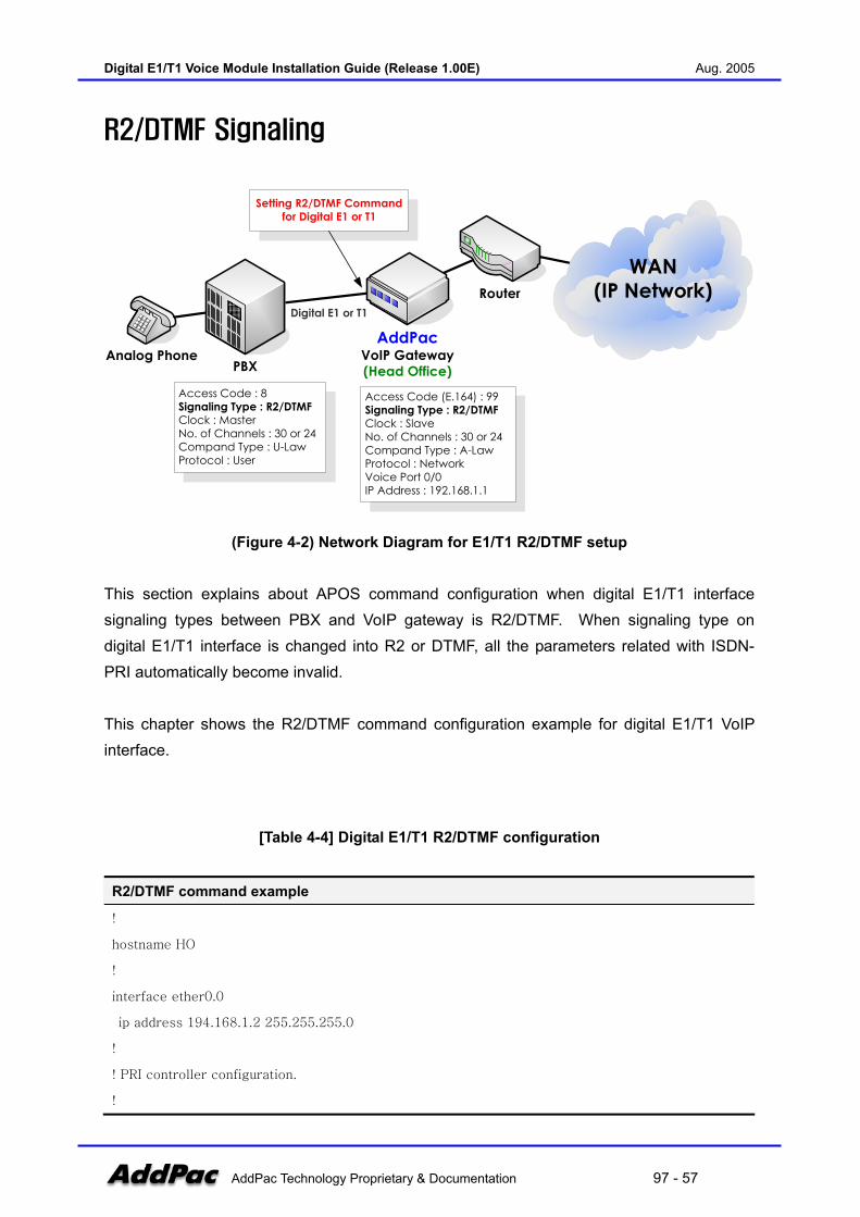
Digital E1/T1 Voice Module Installation Guide (Release 1.00E) Aug. 2005
AddPac Technology Proprietary & Documentation 97 - 57
R2/DTMF Signaling
WAN(IP Network)
Analog Phone
Router
AddPacVoIP Gateway(Head Office)PBX
Access Code : 8Signaling Type : R2/DTMFClock : MasterNo. of Channels : 30 or 24Compand Type : U-LawProtocol : User
Access Code (E.164) : 99Signaling Type : R2/DTMFClock : SlaveNo. of Channels : 30 or 24Compand Type : A-LawProtocol : NetworkVoice Port 0/0IP Address : 192.168.1.1
Setting R2/DTMF Command for Digital E1 or T1
Digital E1 or T1
(Figure 4-2) Network Diagram for E1/T1 R2/DTMF setup
This section explains about APOS command configuration when digital E1/T1 interface signaling types between PBX and VoIP gateway is R2/DTMF. When signaling type on digital E1/T1 interface is changed into R2 or DTMF, all the parameters related with ISDN-PRI automatically become invalid. This chapter shows the R2/DTMF command configuration example for digital E1/T1 VoIP interface.
[Table 4-4] Digital E1/T1 R2/DTMF configuration
R2/DTMF command example
!
hostname HO
!
interface ether0.0
ip address 194.168.1.2 255.255.255.0
!
! PRI controller configuration.
!
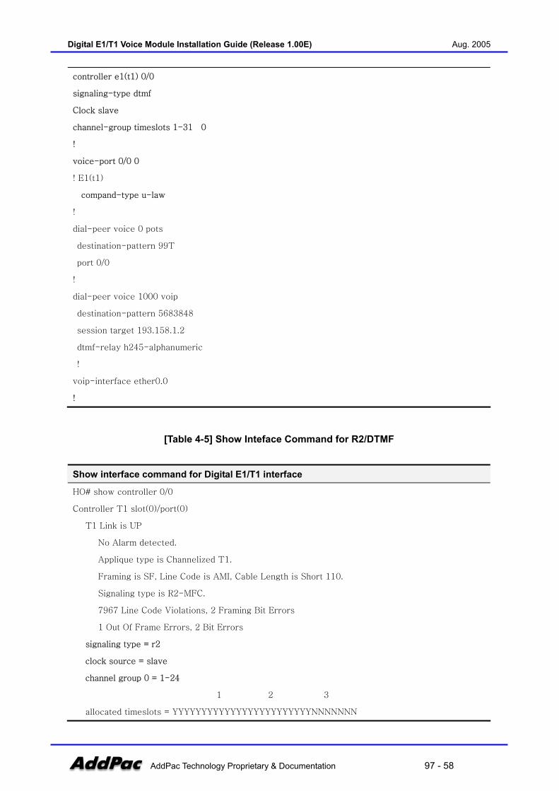
Digital E1/T1 Voice Module Installation Guide (Release 1.00E) Aug. 2005
AddPac Technology Proprietary & Documentation 97 - 58
controller e1(t1) 0/0
signaling-type dtmf
Clock slave
channel-group timeslots 1-31 0
!
voice-port 0/0 0
! E1(t1)
compand-type u-law
!
dial-peer voice 0 pots
destination-pattern 99T
port 0/0
!
dial-peer voice 1000 voip
destination-pattern 5683848
session target 193.158.1.2
dtmf-relay h245-alphanumeric
!
voip-interface ether0.0
!
[Table 4-5] Show Inteface Command for R2/DTMF
Show interface command for Digital E1/T1 interface
HO# show controller 0/0
Controller T1 slot(0)/port(0)
T1 Link is UP
No Alarm detected.
Applique type is Channelized T1.
Framing is SF, Line Code is AMI, Cable Length is Short 110.
Signaling type is R2-MFC.
7967 Line Code Violations, 2 Framing Bit Errors
1 Out Of Frame Errors, 2 Bit Errors
signaling type = r2
clock source = slave
channel group 0 = 1-24
1 2 3
allocated timeslots = YYYYYYYYYYYYYYYYYYYYYYYYNNNNNNN

Digital E1/T1 Voice Module Installation Guide (Release 1.00E) Aug. 2005
AddPac Technology Proprietary & Documentation 97 - 59
outgoing barred channel group =
channel order = descending
b-channel negotiation = exclusive
overlap receiving = enabled
protocol side = network
R2 get calling number = disabled
ISDN virtual connect = disabled
T1 cable length = short 110
T1 framing = sf
T1 line code = ami
T1 CAS type = immediate
[Table 4-6] R2/DTMF Configuration commands
Step APOS Command Purpose
1 HO(config-ether0.0)# controller e1 0/0 Enter E1 interfase configuration
mode.
2 HO(config-ether0.0)# signaling-type dtmf Specify E1 signaling type as
DTMF.
3 HO(config-ether0.0)# clock slave
4 HO(config-ether0.0)# channel-group timeslots 1-31 0
5 HO(config-ether0.0)# voice-port 0/0
6 HO(config)# compand-type u-law
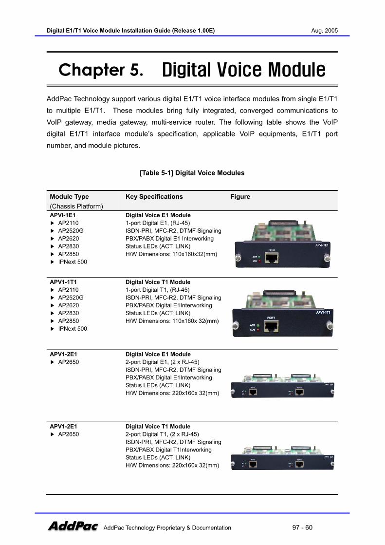
Digital E1/T1 Voice Module Installation Guide (Release 1.00E) Aug. 2005
AddPac Technology Proprietary & Documentation 97 - 60
Chapter 5. Digital Voice Module AddPac Technology support various digital E1/T1 voice interface modules from single E1/T1 to multiple E1/T1. These modules bring fully integrated, converged communications to VoIP gateway, media gateway, multi-service router. The following table shows the VoIP digital E1/T1 interface module’s specification, applicable VoIP equipments, E1/T1 port number, and module pictures.
[Table 5-1] Digital Voice Modules
Module Type (Chassis Platform)
Key Specifications Figure
APVI-1E1 AP2110 AP2520G AP2620 AP2830 AP2850 IPNext 500
Digital Voice E1 Module 1-port Digital E1, (RJ-45) ISDN-PRI, MFC-R2, DTMF Signaling PBX/PABX Digital E1 Interworking Status LEDs (ACT, LINK) H/W Dimensions: 110x160x32(mm)
APV1-1T1 AP2110 AP2520G AP2620 AP2830 AP2850 IPNext 500
Digital Voice T1 Module 1-port Digital T1, (RJ-45) ISDN-PRI, MFC-R2, DTMF Signaling PBX/PABX Digital E1Interworking Status LEDs (ACT, LINK) H/W Dimensions: 110x160x 32(mm)
APV1-2E1 AP2650
Digital Voice E1 Module 2-port Digital E1, (2 x RJ-45) ISDN-PRI, MFC-R2, DTMF Signaling PBX/PABX Digital E1Interworking Status LEDs (ACT, LINK) H/W Dimensions: 220x160x 32(mm)
APV1-2E1 AP2650
Digital Voice T1 Module 2-port Digital T1, (2 x RJ-45) ISDN-PRI, MFC-R2, DTMF Signaling PBX/PABX Digital T1Interworking Status LEDs (ACT, LINK) H/W Dimensions: 220x160x 32(mm)

Digital E1/T1 Voice Module Installation Guide (Release 1.00E) Aug. 2005
AddPac Technology Proprietary & Documentation 97 - 61
APV2-1E1 AP-MG3000
Digital Voice T1 Module 1-port Digital E1, (RJ-45) ISDN-PRI, MFC-R2, DTMF Signaling PBX/PABX Digital E1Interworking Status LEDs (ACT, LINK) H/W Dimensions: 110x160x 32(mm)
APV2-1T1 AP-MG3000
Digital Voice T1 Module 1-port Digital T1, (RJ-45) ISDN-PRI, MFC-R2, DTMF Signaling PBX/PABX Digital E1Interworking Status LEDs (ACT, LINK) H/W Dimensions: 110x160x 32(mm)
APV2-2E1 AP-MG3000
Digital Voice E1 Module 2-port Digital E1, (2 x RJ-45) ISDN-PRI, MFC-R2, DTMF Signaling PBX/PABX Digital E1Interworking Status LEDs (ACT, LINK) H/W Dimensions : 110x160x 32(mm)
APV2-2T1 AP-MG3000
Digital Voice T1 Module 1-port Digital T1, (2 x RJ-45) ISDN-PRI, MFC-R2, DTMF Signaling PBX/PABX Digital E1Interworking Status LEDs (ACT, LINK) H/W Dimensions: 110x160x 32(mm)
APV2-4E1 AP-MG3000
Digital Voice E1 Module 4-port Digital E1, (4 x RJ-45) ISDN-PRI, MFC-R2, DTMF Signaling PBX/PABX Digital E1Interworking Status LEDs (ACT, LINK) H/W Dimensions: 110x160x 32(mm)
APV2-4T1 AP-MG3000
Digital Voice T1 Module 4-port Digital T1, (4 x RJ-45) ISDN-PRI, MFC-R2, DTMF Signaling PBX/PABX Digital E1Interworking Status LEDs (ACT, LINK) H/W Dimensions: 110x160x 32(mm)

Digital E1/T1 Voice Module Installation Guide (Release 1.00E) Aug. 2005
AddPac Technology Proprietary & Documentation 97 - 62
AIM-VoIP2E1 AP4820 AP5840
Digital Voice Module 2-port Digital T1, (4 x RJ-45) ISDN-PRI, MFC-R2, DTMF Signaling PBX/PABX Digital E1Interworking Status LEDs (ACT, LINK) H/W Dimensions: 139x162x 37(mm)
AIM-VoIP4E1 AP4820 AP5840
Digital Voice Module 4-port Digital T1, (4 x RJ-45) ISDN-PRI, MFC-R2, DTMF Signaling PBX/PABX Digital E1Interworking Status LEDs (ACT, LINK) H/W Dimensions: 139x162x 37(mm)
HIM-VoIP2E1 AP5850 AP-MG5000
Digital Voice Module 2-port Digital E1/T1, (2 x RJ-45) ISDN-PRI, MFC-R2, DTMF Signaling SS7 Signaling PBX/PABX Digital E1Interworking Status LEDs (ACT, LINK) H/W Dimensions: 165x215x 25(mm)
HIM-VoIP4E1 AP5850 AP-MG5000
Digital voice module 4-port Digital E1/T1 (4 x RJ-45) ISDN-PRI, MFC-R2, DTMF Signaling SS7 Signaling PBX/PABX Digital E1Interworking Status LEDs (ACT, LINK) H/W Dimensions: 165x215x 25(mm)
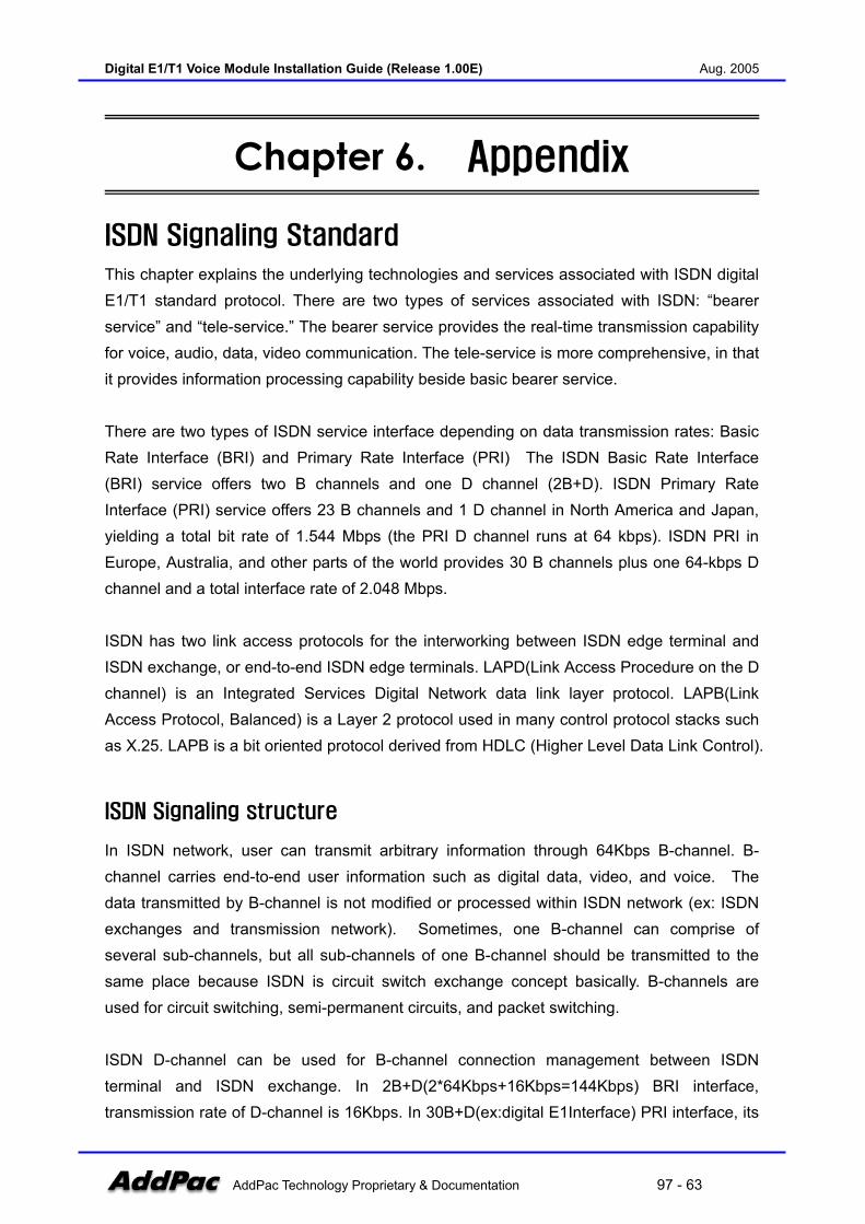
Digital E1/T1 Voice Module Installation Guide (Release 1.00E) Aug. 2005
AddPac Technology Proprietary & Documentation 97 - 63
Chapter 6. Appendix
ISDN Signaling Standard
This chapter explains the underlying technologies and services associated with ISDN digital E1/T1 standard protocol. There are two types of services associated with ISDN: “bearer service” and “tele-service.” The bearer service provides the real-time transmission capability for voice, audio, data, video communication. The tele-service is more comprehensive, in that it provides information processing capability beside basic bearer service. There are two types of ISDN service interface depending on data transmission rates: Basic Rate Interface (BRI) and Primary Rate Interface (PRI) The ISDN Basic Rate Interface (BRI) service offers two B channels and one D channel (2B+D). ISDN Primary Rate Interface (PRI) service offers 23 B channels and 1 D channel in North America and Japan, yielding a total bit rate of 1.544 Mbps (the PRI D channel runs at 64 kbps). ISDN PRI in Europe, Australia, and other parts of the world provides 30 B channels plus one 64-kbps D channel and a total interface rate of 2.048 Mbps. ISDN has two link access protocols for the interworking between ISDN edge terminal and ISDN exchange, or end-to-end ISDN edge terminals. LAPD(Link Access Procedure on the D channel) is an Integrated Services Digital Network data link layer protocol. LAPB(Link Access Protocol, Balanced) is a Layer 2 protocol used in many control protocol stacks such as X.25. LAPB is a bit oriented protocol derived from HDLC (Higher Level Data Link Control).
ISDN Signaling structure
In ISDN network, user can transmit arbitrary information through 64Kbps B-channel. B-channel carries end-to-end user information such as digital data, video, and voice. The data transmitted by B-channel is not modified or processed within ISDN network (ex: ISDN exchanges and transmission network). Sometimes, one B-channel can comprise of several sub-channels, but all sub-channels of one B-channel should be transmitted to the same place because ISDN is circuit switch exchange concept basically. B-channels are used for circuit switching, semi-permanent circuits, and packet switching. ISDN D-channel can be used for B-channel connection management between ISDN terminal and ISDN exchange. In 2B+D(2*64Kbps+16Kbps=144Kbps) BRI interface, transmission rate of D-channel is 16Kbps. In 30B+D(ex:digital E1Interface) PRI interface, its
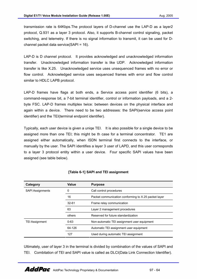
Digital E1/T1 Voice Module Installation Guide (Release 1.00E) Aug. 2005
AddPac Technology Proprietary & Documentation 97 - 64
transmission rate is 64Kbps.The protocol layers of D-channel use the LAP-D as a layer2 protocol, Q.931 as a layer 3 protocol. Also, it supports B-channel control signaling, packet switching, and telemetry. If there is no signal information to transmit, it can be used for D-channel packet data service(SAPI = 16). LAP-D is D channel protocol. It provides acknowledged and unacknowledged information transfer. Unacknowledged information transfer is like UDP. Acknowledged information transfer is like X.25. Unacknowledged service uses unsequenced frames with no error or flow control. Acknowledged service uses sequenced frames with error and flow control similar to HDLC LAPB protocol. LAP-D frames have flags at both ends, a Service access point identifier (6 bits), a command-response bit, a 7-bit terminal identifier, control or information payloads, and a 2-byte FSC. LAP-D frames multiplex twice: between devices on the physical interface and again within a device. There need to be two addresses: the SAPI(service access point identifier) and the TEI(terminal endpoint identifier). Typically, each user device is given a uniqe TEI. It is also possible for a single device to be assigned more than one TEI; this might be th case for a terminal concentrator. TE1 are assigned either automatically, when ISDN terminal first connects to the interface, or manually by the user. The SAPI identifies a layer 3 user of LAPD, and this user corresponds to a layer 3 protocol entity within a user device. Four specific SAPI values have been assigned (see table below).
[Table 6-1] SAPI and TEI assignment
Category Value Purpose
0 Call control procedures
16 Packet communication conforming to X.25 packet layer
32-61 Frame relay communication
63 Layer 2 management procedures
SAPI Assignments
others Reserved for future standardization
0-63 Non-automatic TEI assignment user equipment
64-126 Automatic TEI assignment user equipment
TEI Assignment
127 Used during automatic TEI assignment
Ultimately, user of layer 3 in the terminal is divided by combination of the values of SAPI and TEI. Combitation of TEI and SAPI value is called as DLCI(Data Link Connection Identifier).

Digital E1/T1 Voice Module Installation Guide (Release 1.00E) Aug. 2005
AddPac Technology Proprietary & Documentation 97 - 65
Channel H performs the same function as B-Channels, but operates at rates exceeding DS-0 (64 Kbps). User can be allocated two kinds of channel combination by ISDN; basic access and primary access.
[Table 6-2] ISDN signaling channel combination
Category Bandwidth Combination Channel B Channel D
ISDN BRI 192Kbps 2B+D+syn. And framing 64Kbps 16Kbps
ISDN PRI(T1) 1.544Mbps 23B+D 64Kbps
ISDN PRI(E1) 2.048Mbps 30B+D
ISDN Layer 3 protocol
Basic Call Control ITU-T Recommendation Q.930(I.450) describes the general call control schemes in ISDN and ITU-T Recommendation Q.931(I.451) describes ISDN user-network interface layer 3 specification for basic call control. Q.931 layer3 protocol describes the call control procedures of circuit switching and packet switching. Each parts of Layer 3 message implement the functions as follows; Protocol Discriminator: Prototols such as Q.931 and X.25 for call control can share channel D. Protocol discriminator shows which protocol the message belongs to. Call Reference Value: At the ISDN user-network Interface, it identifies which value the requirement related with call control belongs to. This value has meaning not in the network but at the ISDN user - network interface. The message, having no part for “call reference value” and “the length of call reference value” is 0, is used for supplementary service. Also the message, “call reference value” is 0, is used for link restart, and for all the call related to relevant DLCI. Message Type: There are the messages related with configuration, release and control of all connection of circuit switching and packet switching described in Q.931. The following figure shows general message sequence for call control.

Digital E1/T1 Voice Module Installation Guide (Release 1.00E) Aug. 2005
AddPac Technology Proprietary & Documentation 97 - 66
(Figure 6-1) ISDN Call control (Q931)
The table bellow has list of possible Q.931 messages seen during call establishment and call clearing; call establishment phase, call information phase, call clearing phase, and miscellaneous.
[Table 6-3] Q.931 messages
Category Messages
call establishment phase ALTERING, CALL PROCEEDING, CONNECT, CONNECT
ACKNOWLEDGE, PROGRESS, SETUP, SETUP ACKNOWLEDGE
call information phase SUSPEND, SUSPEND ACKNOWLEDGE, SUSPEND REJECT, RESUME,
RESUME ACKNOWLEDGE, RESUME REJECT, USER INFORMATION
call clearing phase DISCONNECT, RELEASE, RELEASE COMPLETE, RESTART,
RESTART ACKNOWLEDGE
miscellaneous CONGESTION CONTROL, FACILITY, INFORMATION, NOTIFY, STATUS,
STATUS ENQUIRY
Call establishment messages are transmitted between (call establishment initiator - network) or (network - call establishment answerer) during call establishment. These messages help user setup channel B call establishment, and help network support requirement for user’s call establishment. Call information phase messages transmit additional informations related with connection while user sets up call extablisment and call clearing or make suspension when it is needed. Call clearing messages release call, and miscellaneous messages are for exchange of

Digital E1/T1 Voice Module Installation Guide (Release 1.00E) Aug. 2005
AddPac Technology Proprietary & Documentation 97 - 67
information such as connection status, network performance. Each messages having these functions are consist of various information elements. Heres are the details about bearer capability information element.
ISDN Message Structure
ISDN layer3 Q.931 message structure consists of protocol discriminator, call reference value, Q.931 message type, information elements. The message type field is used for Q.931 layer3 message (SETUP, ALERT, CALL PROCEEDING, etc) identification. A Q.931 message such as SETUP message has several information elements such as bearer capability, called party address, calling party address, etc through the extension field, information element idenfier, length of information elements.
8 7 6 5 4 3 2 1
Protocol discriminator
0 0 0 0 Length of reference call value
Flag Call reference value
0 Message type
Other information elements as required
1 Information element identifier Information element
0 Information element identifier
Length of information elements
Information elements (multiple bytes)
(Figure 6-2) ISDN Message Structure
Protocol discriminator ISDN protocol discriminator length of call reference value Define the length of call reference value. Flag Set to 1 or 0. 1: messages sent by party that allocated the call reference value 0: other
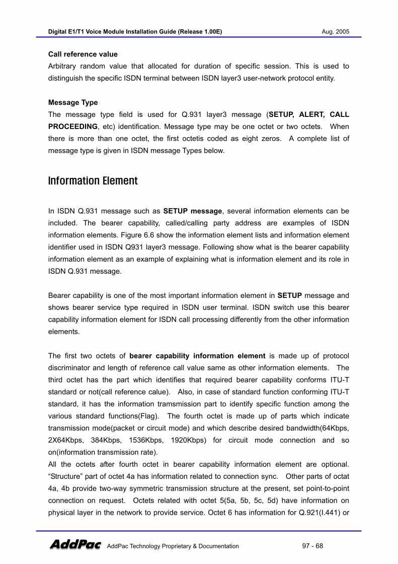
Digital E1/T1 Voice Module Installation Guide (Release 1.00E) Aug. 2005
AddPac Technology Proprietary & Documentation 97 - 68
Call reference value Arbitrary random value that allocated for duration of specific session. This is used to distinguish the specific ISDN terminal between ISDN layer3 user-network protocol entity. Message Type The message type field is used for Q.931 layer3 message (SETUP, ALERT, CALL PROCEEDING, etc) identification. Message type may be one octet or two octets. When there is more than one octet, the first octetis coded as eight zeros. A complete list of message type is given in ISDN message Types below.
Information Element
In ISDN Q.931 message such as SETUP message, several information elements can be included. The bearer capability, called/calling party address are examples of ISDN information elements. Figure 6.6 show the information element lists and information element identifier used in ISDN Q931 layer3 message. Following show what is the bearer capability information element as an example of explaining what is information element and its role in ISDN Q.931 message. Bearer capability is one of the most important information element in SETUP message and shows bearer service type required in ISDN user terminal. ISDN switch use this bearer capability information element for ISDN call processing differently from the other information elements. The first two octets of bearer capability information element is made up of protocol discriminator and length of reference call value same as other information elements. The third octet has the part which identifies that required bearer capability conforms ITU-T standard or not(call reference calue). Also, in case of standard function conforming ITU-T standard, it has the information tramsmission part to identify specific function among the various standard functions(Flag). The fourth octet is made up of parts which indicate transmission mode(packet or circuit mode) and which describe desired bandwidth(64Kbps, 2X64Kbps, 384Kbps, 1536Kbps, 1920Kbps) for circuit mode connection and so on(information transmission rate). All the octets after fourth octet in bearer capability information element are optional. “Structure” part of octet 4a has information related to connection sync. Other parts of octat 4a, 4b provide two-way symmetric transmission structure at the present, set point-to-point connection on request. Octets related with octet 5(5a, 5b, 5c, 5d) have information on physical layer in the network to provide service. Octet 6 has information for Q.921(I.441) or
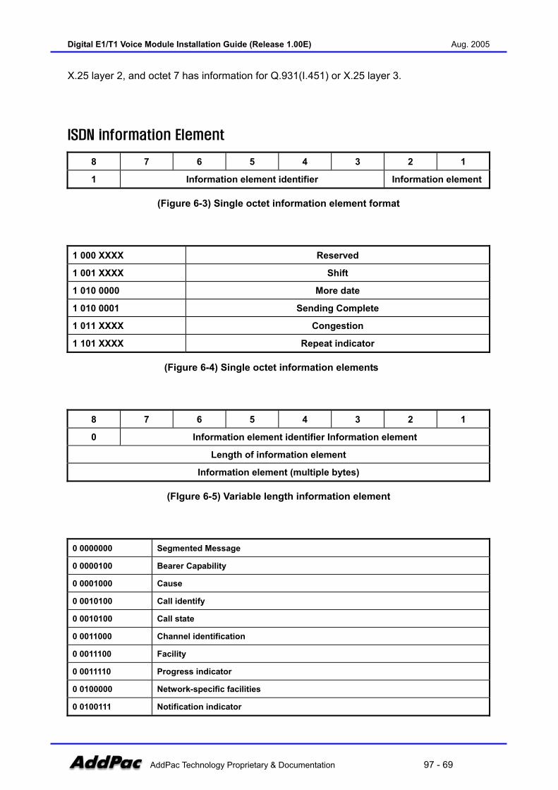
Digital E1/T1 Voice Module Installation Guide (Release 1.00E) Aug. 2005
AddPac Technology Proprietary & Documentation 97 - 69
X.25 layer 2, and octet 7 has information for Q.931(I.451) or X.25 layer 3.
ISDN information Element
8 7 6 5 4 3 2 1
1 Information element identifier Information element
(Figure 6-3) Single octet information element format
1 000 XXXX Reserved
1 001 XXXX Shift
1 010 0000 More date
1 010 0001 Sending Complete
1 011 XXXX Congestion
1 101 XXXX Repeat indicator
(Figure 6-4) Single octet information elements
8 7 6 5 4 3 2 1
0 Information element identifier Information element
Length of information element
Information element (multiple bytes)
(FIgure 6-5) Variable length information element
0 0000000 Segmented Message
0 0000100 Bearer Capability
0 0001000 Cause
0 0010100 Call identify
0 0010100 Call state
0 0011000 Channel identification
0 0011100 Facility
0 0011110 Progress indicator
0 0100000 Network-specific facilities
0 0100111 Notification indicator

Digital E1/T1 Voice Module Installation Guide (Release 1.00E) Aug. 2005
AddPac Technology Proprietary & Documentation 97 - 70
0 0101000 Display
0 0101001 Date/time
0 0101100 Keypad facility
0 0110100 Signal
0 0110110 Switchhook
0 0111000 Feature activation
0 0111001 Feature indication
0 1000000 Information rate
0 1000010 End-to-end transit delay
0 1000011 Transit delay selection and indication
0 1000100 Packet layer binary parameters
0 1000101 Packet layer window size
0 1000110 Packet size
0 1101100 Calling party number
0 1101101 Calling party subaddress
0 1110000 Called party number
0 1110001 Called Party subaddress
0 1110100 Redirecting number
0 1111000 Transit network selection
0 1111001 Restart indicator
0 1111100 Low layer compatibility
0 1111101 High layer compatibility
0 1111110 User-user
0 1111111 Escape for ex
Other values Reserved
(FIgure 6-6) Information element identifier
ISDN Message Type
000 00001 Alerting
000 00010 Call Proceeding
000 00011 Progress
000 00101 Setup
000 00111 Connect
000 01101 Setup Acknowledge
000 01111 Connect Acknowledge
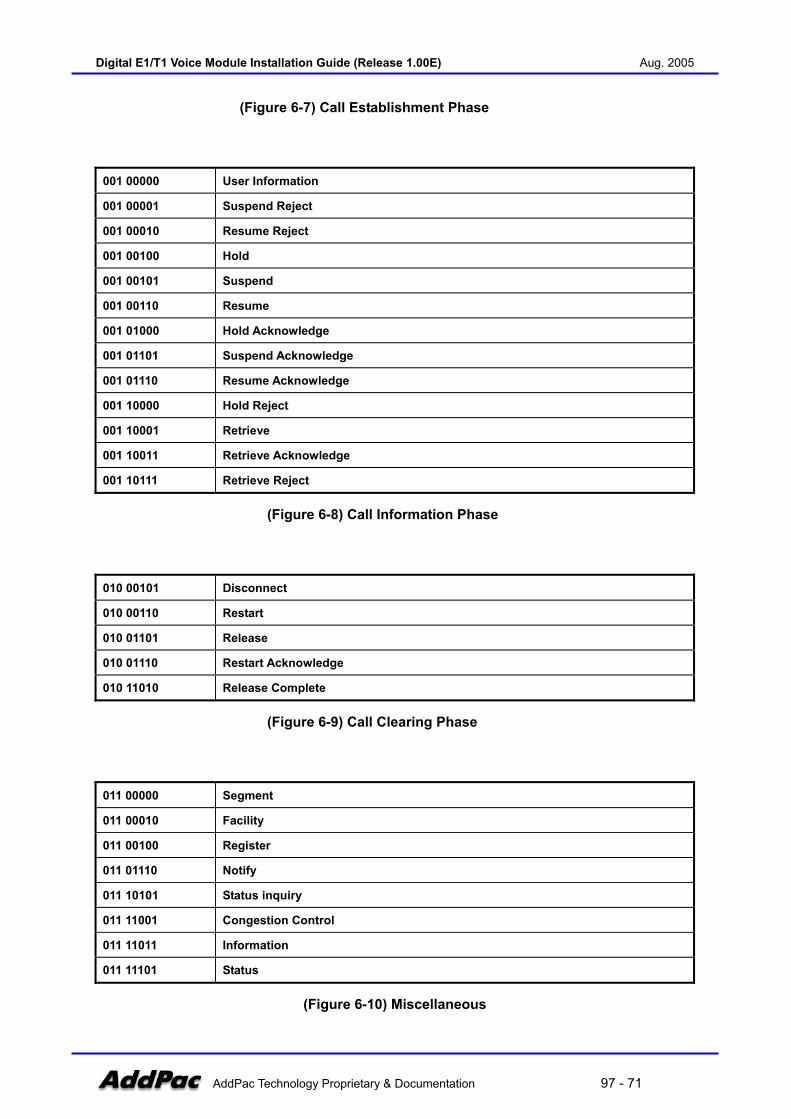
Digital E1/T1 Voice Module Installation Guide (Release 1.00E) Aug. 2005
AddPac Technology Proprietary & Documentation 97 - 71
(Figure 6-7) Call Establishment Phase
001 00000 User Information
001 00001 Suspend Reject
001 00010 Resume Reject
001 00100 Hold
001 00101 Suspend
001 00110 Resume
001 01000 Hold Acknowledge
001 01101 Suspend Acknowledge
001 01110 Resume Acknowledge
001 10000 Hold Reject
001 10001 Retrieve
001 10011 Retrieve Acknowledge
001 10111 Retrieve Reject
(Figure 6-8) Call Information Phase
010 00101 Disconnect
010 00110 Restart
010 01101 Release
010 01110 Restart Acknowledge
010 11010 Release Complete
(Figure 6-9) Call Clearing Phase
011 00000 Segment
011 00010 Facility
011 00100 Register
011 01110 Notify
011 10101 Status inquiry
011 11001 Congestion Control
011 11011 Information
011 11101 Status
(Figure 6-10) Miscellaneous

Digital E1/T1 Voice Module Installation Guide (Release 1.00E) Aug. 2005
AddPac Technology Proprietary & Documentation 97 - 72
International Variants of ISDN
ISDN is presented at CCITT(Comite Consultatif Internationale de Telegraphique et Telephonique or Consultative Committee on International Telephone and Telegraphy) conference in november of 1980. Prior to this publication, various geographical areas had developed different versions of ISDN.
Following is a description of most ISDN variants: National ISDN1(Bellcore) This variant is used in U.S. by Bellcore. It has four(4) network-specific message types. It
does not have any single octet information elements. In addition to Codeset 0 elements it
has four(4) Codeset 5 and five(5) Codeset 6 information elements.
National ISDN-2(Bellcore) The main difference between national ISDN-1 and ISDN-2 is parameter downloading via
components. These components are used to communicate parameter information between
ISDN terminal such as ISDN phone, ISDN TA, ISDN video phone and the ISDN switch.
Other changes are the addition of the SEGMENT, FACILITY and REGISTER message type
and the segmented message and extended facility information elements.
5ESS(AT&T) This variant is used in U.S. by AT&T. It is the most widely used of the ISDN protocols and
contains nineteen(19) network-specific message types. It does not have Codeset 5, but
does have eighteen(18) Codeset 6 elements and an extensive information management
element.
Euro ISDN(ETSI) This variant is to be adopted by all of the Erupean countries. Presently, it contains single
octet message types and has five(5) single octet information elements. Within the framework
of the protocol there are no Codeset 5 and Codeset 6 elements, however each country is
permitted to define its own individual elements.
VN3, VN4(France) There variants are prevalent in France. The VN3 decoding and some of its error messages
are translated into French. It is a sub-set of the CCITT document and only has single octet
message types. The more recent VN4 is not fully backward compatible but closely follows
the CCITT recommendations. As with VN3, some translation has taken place. It has only
single octet message types, five(5) single octet information elements, and two(2) Codeset 6
Digital E1/T1 Voice Module Installation Guide (Release 1.00E) Aug. 2005
AddPac Technology Proprietary & Documentation 97 - 73
elements.
1TR6(Germany) This variant is prevalent in Germany. It is a sub-set of the CCITT version, with minor
amendments. The protocol’s language is English partly and German partly.
ISDN 30[DASS-2] (Britain) This variant is used by British Telecom in addition to ETSI(see above). At layers 2 and 3 this
standard does not conform to CCITT recommendation. Frames are headed by one octet and
optionally followed by information. However, most of the information is IA5 coded, and
therefore ASCII decoded.
Australia This protocol is being superseded by a new Australian protocol (The name of the protocol
has not been released). It is a subset of the CCITT standard and has only single octet
message types and information elements; it only has Codeset 5 elements.
TS014 Australia This is the new Australian ISDN PRI standard issued by Austel. This standard is very smilat
to ETSI.
NTT-Japan The Japanese ISDN service provided by NTT is known as INS-Net and its main features are
as follow:
• Provides a user-network interface that conforms to the CCITT recommendation blue book • Provides both BRI(basic rate interface) and PRI (primary rate interfaces). • Provides a packet-mode using Case B. • Supported by signalling system No. 7 ISDN user art with the network. • Offered as a public network service.
ARINC 746 In passenger airlines today there are phones in front of each passenger. These telephones
are connected in T1 network and the conversation channel is establsihed via a satellite. The
signaling protocol used is based on Q.931, but with a few modifications and is known as
ARINC 746. The leading companies in this area are GTE and AT&T. In order to analyze
ARINC, the LAPD variant should also be specified as ARINC.
Digital E1/T1 Voice Module Installation Guide (Release 1.00E) Aug. 2005
AddPac Technology Proprietary & Documentation 97 - 74
ARINC 746 Attachment 11 ARINC (Aeronautical Radio, INC.) Attachment 11 describes the network layer(layer 3)
message necessary for equipment control and circuit switched all control procedures
between the Cabin Telecommunications Unit(CTU) and SATCOM system, North American
Telephone System(NATS), and Terrestrial Flight Telephone System(TFTS). The interface
described in this attachment is derived from the CCITT recommendations Q.930, Q931 and
Q.932 for call control and the ISO/OSI standards DIS 9595 and DIS 9596 for equipment
control.
ARINC 746 Attachment 17 ARINC(Aeronautical Radio, INC) Attachment 17 represents a system which provides
passenger and cabin crew access to services provided by the CTU and intelligent cabin
equipment. The distribution portion of the CDS transports the signaling and voice channels
from headend units to the individual seat units. Each zone within the aircraft has a zone unit
that controls and services seat units within that zone.
Northern Telecom - DMS 100 This variant represents Northen Telecom’s implementation of National ISDN-1. It provides
ISDN BRI user-network interfaces between the Northen Telecom ISDN DMS-100 switch and
ISDN terminals designed for ISDN BRI(basic rate interface: 2B+D). It is based on CCITT
ISDN-1 and Q Series Recommendations and the ISDN BRI Interface call control switching
and signaling requirements and supplementary service technical references published by
Bellcore.
DPNSS1 DPNSS1(Digital Private Network Signaling System No. 1) is a common channel signaling
system used in Britain. It extends facilities normally only available between extensions on a
single PBX to all extensions on PBXs that are connected together in a private network. It is
primarily intended for use between PBXs in private networks via time-slot 16 of a 2048 kbit/s
digital transmission system. Similarly it may be used in time-slot 24 of a 1.544 kbit/s digital
transmission system. Note that the LAPD variant should also be selected to be DPNSS1.
Swiss Telecom The ISDN variant operated by the Swiss Telecom PTT is called SwissNet. The DSS1
protocol for SwissNet is fully based on ETS. Amendments to this standard for SwissNet fall
into the category of definitions of various options in the standard and of missing

Digital E1/T1 Voice Module Installation Guide (Release 1.00E) Aug. 2005
AddPac Technology Proprietary & Documentation 97 - 75
requirements. They also address SwissNet-specific conditions, e.g., assuring compatibility
between user equipment SwissNet exchanges of different evolution step.
QSIG QSIG is a modern, powerful and intelligent inter-private PABX signaling system. QSIG
standards specify a signaling system at the Q reference point which is primarily intended for
use on a common channel; e.g. a G.703 interface.
However, QSIG will work on any suitable method of connecting the PINX equipment. The
QSIG protocol stack is identical in structure to the DSSI protocol stack. Both follow the ISO
reference model.

Digital E1/T1 Voice Module Installation Guide (Release 1.00E) Aug. 2005
AddPac Technology Proprietary & Documentation 97 - 76
R2 Signaling Standard
MFC-R2 signaling
The R2 protocol is a signaling protocol in an inter-register family of signaling systems standardized by the ITU-T. R2 is used mostly in Europe and other regions in the world, but is not used in North America. The "R" stands for Regional standard recommendation and includes ITU-T Q-series standards, Q.400 to Q.490 and the "2" stands for the second regional standard. R2 is used over trunks in an international telecommunications system. As is known in the telecommunication arts, a trunk is a circuit connecting two switching elements such as telecommunication exchanges. Trunks are combined into trunk groups, creating a high capacity circuit capable of transmitting multiple channels of information between two telecommunication exchanges. The R2 protocol is broken down into two parts: line signaling; and register signaling. Line signaling coveys call status information about a state of a call such as off-hook, on-hook, busy, etc. with call setup and call tear down states (e.g., idle, seize, seize acknowledgment, answered, clear-back, clear-forward and blocked). Register signaling, also known as Multi-Frequency Compelled ("MFC") signaling, is used for addressing. It conveys an ANI ("Automatic Number Identification", i.e., a calling number) and a DNIS ("Dialed Number Identification Service", i.e., a called number), a calling party's category and other network connections with handshaking or an acknowledgment process that includes "forward" (i.e., send) and "backward" (i.e., receive) signals. A forward signal is the signal transmitted by an R2 outgoing register to a remote R2 incoming register. When the signal is confirmed by an R2 incoming register, a backward signal is then transmitted back to the R2 outgoing register. For register signaling in the MFC mode, compelled signaling is achieved by sending pairs of two out of six designated frequencies simultaneously. A maximum of six frequencies are used for signaling between international telecommunication exchanges. Different sets of frequencies are used for the forward and backward signals. This provides a total of 15 multi-frequency combinations in each direction (i.e., forward and backward) for a maximum of 30. Each combination number has a defined meaning of a signal that varies with different forward and backward groups.
Signaling System
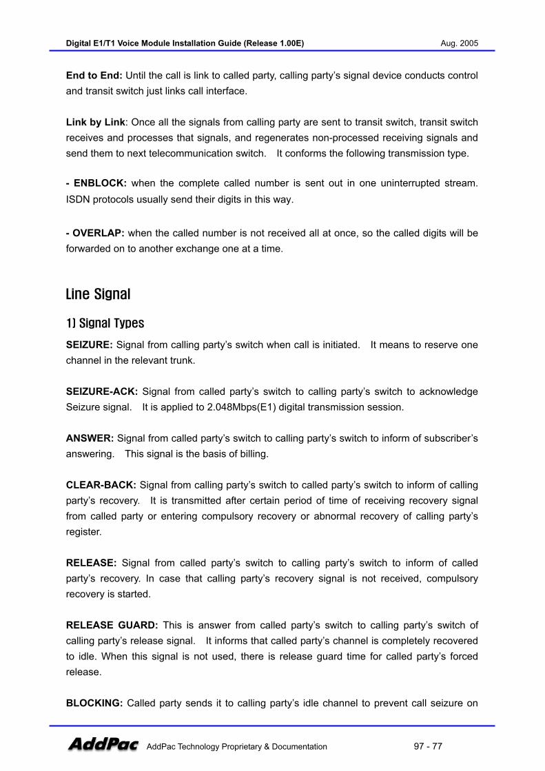
Digital E1/T1 Voice Module Installation Guide (Release 1.00E) Aug. 2005
AddPac Technology Proprietary & Documentation 97 - 77
End to End: Until the call is link to called party, calling party’s signal device conducts control and transit switch just links call interface. Link by Link: Once all the signals from calling party are sent to transit switch, transit switch receives and processes that signals, and regenerates non-processed receiving signals and send them to next telecommunication switch. It conforms the following transmission type. - ENBLOCK: when the complete called number is sent out in one uninterrupted stream. ISDN protocols usually send their digits in this way.
- OVERLAP: when the called number is not received all at once, so the called digits will be forwarded on to another exchange one at a time.
Line Signal
1) Signal Types
SEIZURE: Signal from calling party’s switch when call is initiated. It means to reserve one channel in the relevant trunk. SEIZURE-ACK: Signal from called party’s switch to calling party’s switch to acknowledge Seizure signal. It is applied to 2.048Mbps(E1) digital transmission session. ANSWER: Signal from called party’s switch to calling party’s switch to inform of subscriber’s answering. This signal is the basis of billing. CLEAR-BACK: Signal from calling party’s switch to called party’s switch to inform of calling party’s recovery. It is transmitted after certain period of time of receiving recovery signal from called party or entering compulsory recovery or abnormal recovery of calling party’s register. RELEASE: Signal from called party’s switch to calling party’s switch to inform of called party’s recovery. In case that calling party’s recovery signal is not received, compulsory recovery is started. RELEASE GUARD: This is answer from called party’s switch to calling party’s switch of calling party’s release signal. It informs that called party’s channel is completely recovered to idle. When this signal is not used, there is release guard time for called party’s forced release. BLOCKING: Called party sends it to calling party’s idle channel to prevent call seizure on
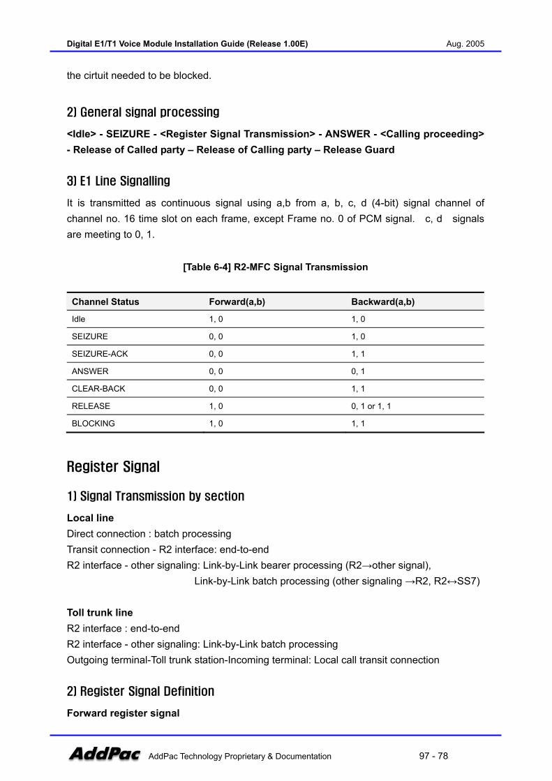
Digital E1/T1 Voice Module Installation Guide (Release 1.00E) Aug. 2005
AddPac Technology Proprietary & Documentation 97 - 78
the cirtuit needed to be blocked.
2) General signal processing
<Idle> - SEIZURE - <Register Signal Transmission> - ANSWER - <Calling proceeding> - Release of Called party – Release of Calling party – Release Guard
3) E1 Line Signalling
It is transmitted as continuous signal using a,b from a, b, c, d (4-bit) signal channel of channel no. 16 time slot on each frame, except Frame no. 0 of PCM signal. c, d signals are meeting to 0, 1.
[Table 6-4] R2-MFC Signal Transmission
Channel Status Forward(a,b) Backward(a,b)
Idle 1, 0 1, 0
SEIZURE 0, 0 1, 0
SEIZURE-ACK 0, 0 1, 1
ANSWER 0, 0 0, 1
CLEAR-BACK 0, 0 1, 1
RELEASE 1, 0 0, 1 or 1, 1
BLOCKING 1, 0 1, 1
Register Signal
1) Signal Transmission by section
Local line Direct connection : batch processing Transit connection - R2 interface: end-to-end R2 interface - other signaling: Link-by-Link bearer processing (R2→other signal),
Link-by-Link batch processing (other signaling →R2, R2↔SS7) Toll trunk line R2 interface : end-to-end R2 interface - other signaling: Link-by-Link batch processing Outgoing terminal-Toll trunk station-Incoming terminal: Local call transit connection
2) Register Signal Definition
Forward register signal
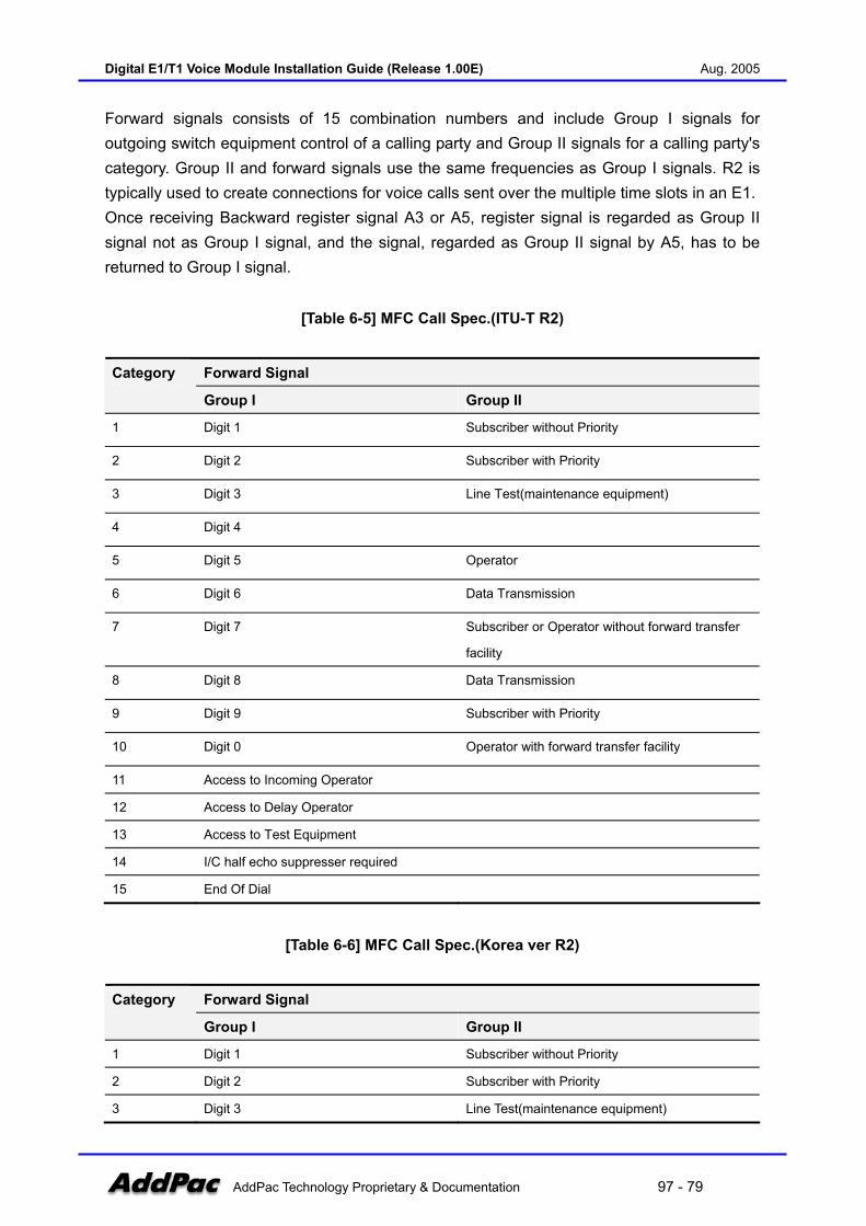
Digital E1/T1 Voice Module Installation Guide (Release 1.00E) Aug. 2005
AddPac Technology Proprietary & Documentation 97 - 79
Forward signals consists of 15 combination numbers and include Group I signals for outgoing switch equipment control of a calling party and Group II signals for a calling party's category. Group II and forward signals use the same frequencies as Group I signals. R2 is typically used to create connections for voice calls sent over the multiple time slots in an E1. Once receiving Backward register signal A3 or A5, register signal is regarded as Group II signal not as Group I signal, and the signal, regarded as Group II signal by A5, has to be returned to Group I signal.
[Table 6-5] MFC Call Spec.(ITU-T R2)
Forward Signal Category
Group I Group II
1 Digit 1 Subscriber without Priority
2 Digit 2 Subscriber with Priority
3 Digit 3 Line Test(maintenance equipment)
4 Digit 4
5 Digit 5 Operator
6 Digit 6 Data Transmission
7 Digit 7 Subscriber or Operator without forward transfer
facility
8 Digit 8 Data Transmission
9 Digit 9 Subscriber with Priority
10 Digit 0 Operator with forward transfer facility
11 Access to Incoming Operator
12 Access to Delay Operator
13 Access to Test Equipment
14 I/C half echo suppresser required
15 End Of Dial
[Table 6-6] MFC Call Spec.(Korea ver R2)
Forward Signal Category
Group I Group II
1 Digit 1 Subscriber without Priority
2 Digit 2 Subscriber with Priority
3 Digit 3 Line Test(maintenance equipment)
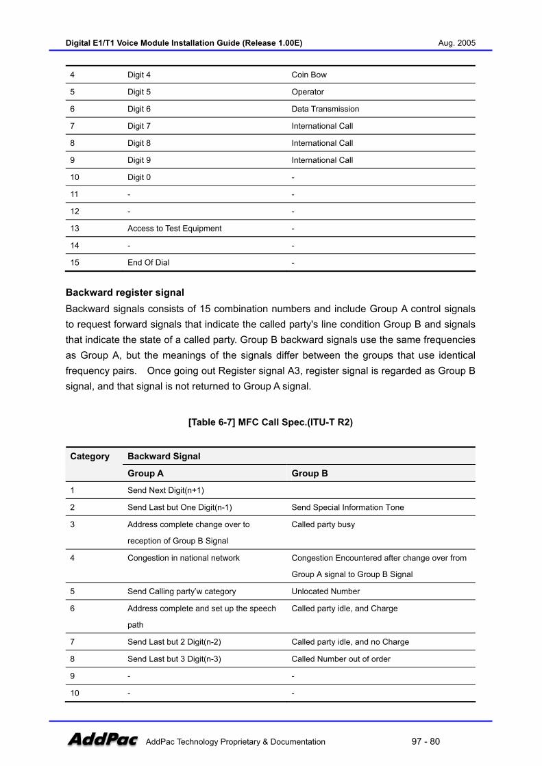
Digital E1/T1 Voice Module Installation Guide (Release 1.00E) Aug. 2005
AddPac Technology Proprietary & Documentation 97 - 80
4 Digit 4 Coin Bow
5 Digit 5 Operator
6 Digit 6 Data Transmission
7 Digit 7 International Call
8 Digit 8 International Call
9 Digit 9 International Call
10 Digit 0 -
11 - -
12 - -
13 Access to Test Equipment -
14 - -
15 End Of Dial -
Backward register signal Backward signals consists of 15 combination numbers and include Group A control signals to request forward signals that indicate the called party's line condition Group B and signals that indicate the state of a called party. Group B backward signals use the same frequencies as Group A, but the meanings of the signals differ between the groups that use identical frequency pairs. Once going out Register signal A3, register signal is regarded as Group B signal, and that signal is not returned to Group A signal.
[Table 6-7] MFC Call Spec.(ITU-T R2)
Backward Signal Category
Group A Group B
1 Send Next Digit(n+1)
2 Send Last but One Digit(n-1) Send Special Information Tone
3 Address complete change over to
reception of Group B Signal
Called party busy
4 Congestion in national network Congestion Encountered after change over from
Group A signal to Group B Signal
5 Send Calling party’w category Unlocated Number
6 Address complete and set up the speech
path
Called party idle, and Charge
7 Send Last but 2 Digit(n-2) Called party idle, and no Charge
8 Send Last but 3 Digit(n-3) Called Number out of order
9 - -
10 - -

Digital E1/T1 Voice Module Installation Guide (Release 1.00E) Aug. 2005
AddPac Technology Proprietary & Documentation 97 - 81
11 Send Country Code Indicator -
12 Send Language or Discrimination Digit -
13 a)Send Nature Of circuit
b)Send Location Of outgoing Internatial
R2 register
-
14 Request for information on use of
exchange Of suppresser
-
15 Congestion in On international exchange
or at it’s Output
-
[Table 6-8] MFC Call Spec.(Korea ver. R2)
Backward Signal Category
Group A Group B
1 Send Next Digit(n+1) Called party release
2 Send Last but One Digit(n-1) Called party busy
3 Address complete change
over of Group B Signal
Called party busy
4 Congestion in national network Congestion Encountered after change over from
Group A signal to Group B Signal
5 Send Calling party’s category Unlocated Number
6 Address complete and set up the speech
path
Called party idle, and Charge
7 Send Last but 2 Digit(n-2) Called party idle, and no Charge
8 Send Last but 3 Digit(n-3) Counter party out of order or restrict of incoming
call
9 Send first Digit of called number Called party idle, and no Charge
* In case of using R2 signaling in DID section, R2 register of PABX must not to feature outgoing A5,
B1, B7 signal of Backword signal.
3) Signaling Procedure
When calling party start digit sending, calling party’s switch accumulates digit. When complete digts are received then starts signaling procedure as follows.
- Select outgoing trunk and send out SEIZURE signal - Send out register signal, which is the first digit signal - Called party relay R2 incoming register signal to incoming trunk
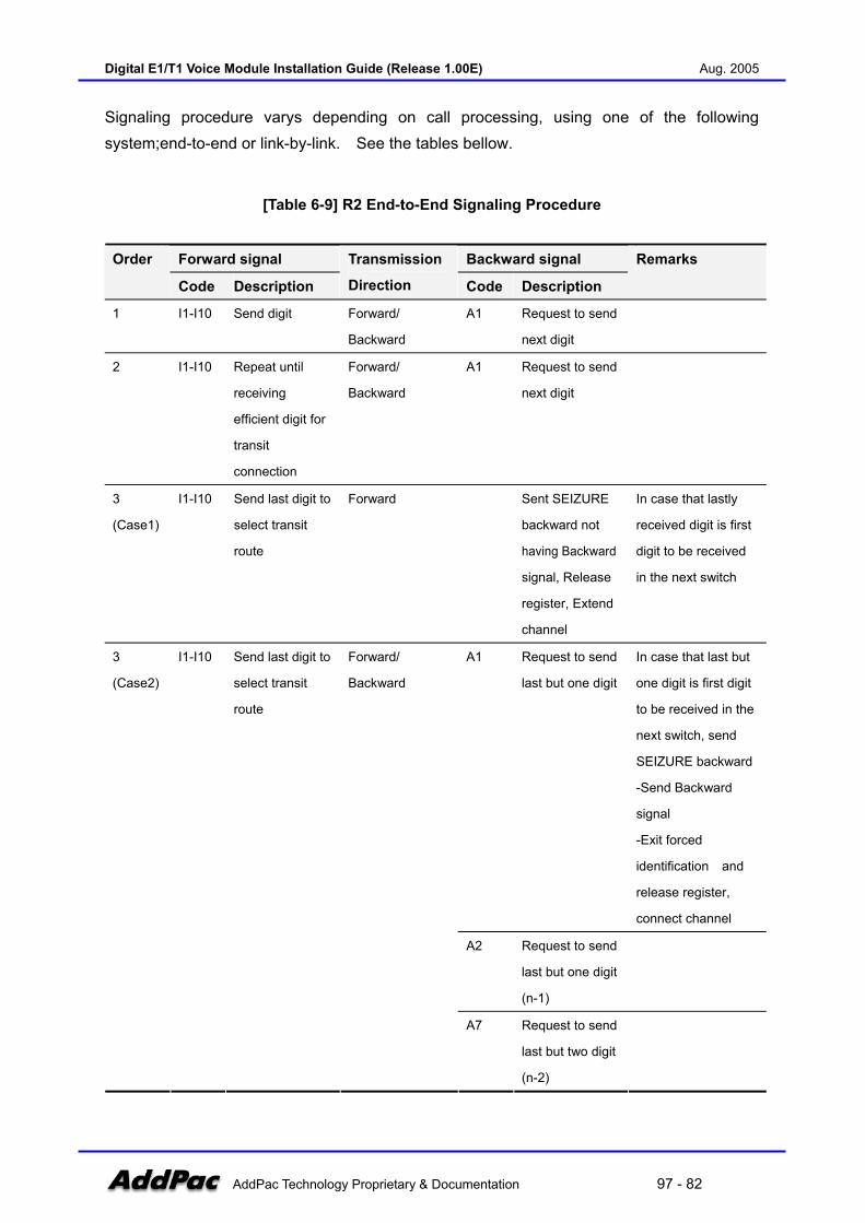
Digital E1/T1 Voice Module Installation Guide (Release 1.00E) Aug. 2005
AddPac Technology Proprietary & Documentation 97 - 82
Signaling procedure varys depending on call processing, using one of the following system;end-to-end or link-by-link. See the tables bellow.
[Table 6-9] R2 End-to-End Signaling Procedure
Forward signal Backward signal Order
Code Description
Transmission
Direction Code Description
Remarks
1 I1-I10 Send digit Forward/
Backward
A1 Request to send
next digit
2 I1-I10 Repeat until
receiving
efficient digit for
transit
connection
Forward/
Backward
A1 Request to send
next digit
3
(Case1)
I1-I10 Send last digit to
select transit
route
Forward Sent SEIZURE
backward not
having Backward
signal, Release
register, Extend
channel
In case that lastly
received digit is first
digit to be received
in the next switch
A1 Request to send
last but one digit
In case that last but
one digit is first digit
to be received in the
next switch, send
SEIZURE backward
-Send Backward
signal
-Exit forced
identification and
release register,
connect channel
A2 Request to send
last but one digit
(n-1)
3
(Case2)
I1-I10 Send last digit to
select transit
route
Forward/
Backward
A7 Request to send
last but two digit
(n-2)
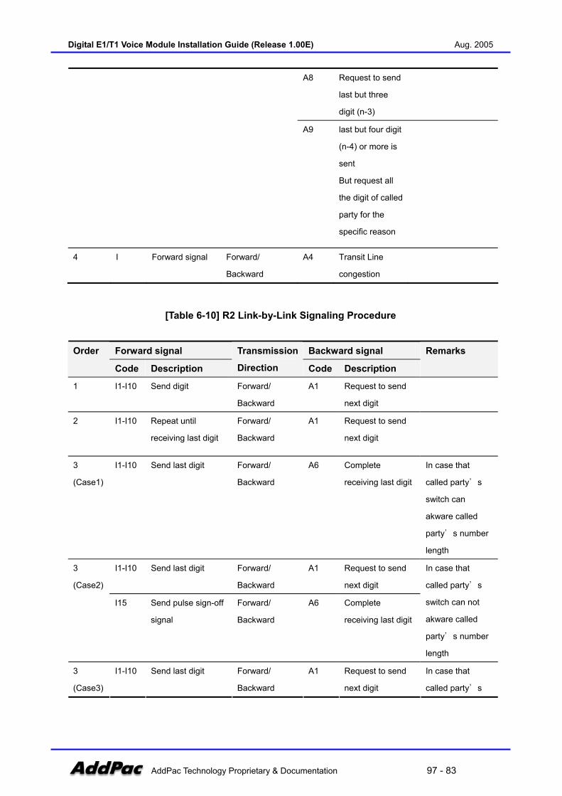
Digital E1/T1 Voice Module Installation Guide (Release 1.00E) Aug. 2005
AddPac Technology Proprietary & Documentation 97 - 83
A8 Request to send
last but three
digit (n-3)
A9 last but four digit
(n-4) or more is
sent
But request all
the digit of called
party for the
specific reason
4 I Forward signal Forward/
Backward
A4 Transit Line
congestion
[Table 6-10] R2 Link-by-Link Signaling Procedure
Forward signal Backward signal Order
Code Description
Transmission
Direction Code Description
Remarks
1 I1-I10 Send digit Forward/
Backward
A1 Request to send
next digit
2 I1-I10 Repeat until
receiving last digit
Forward/
Backward
A1 Request to send
next digit
3
(Case1)
I1-I10 Send last digit Forward/
Backward
A6 Complete
receiving last digit
In case that
called party’s
switch can
akware called
party’s number
length
I1-I10 Send last digit Forward/
Backward
A1 Request to send
next digit
3
(Case2)
I15 Send pulse sign-off
signal
Forward/
Backward
A6 Complete
receiving last digit
In case that
called party’s
switch can not
akware called
party’s number
length
3
(Case3)
I1-I10 Send last digit Forward/
Backward
A1 Request to send
next digit
In case that
called party’s

Digital E1/T1 Voice Module Installation Guide (Release 1.00E) Aug. 2005
AddPac Technology Proprietary & Documentation 97 - 84
Backward A6 Transmit last digit
receiving
completion signal
after timeout(5
sec.) for last digit
decision
switch can not
akware called
party’s number
length and calling
party’s switch
can not send
pulse sign-off
4 I Forward signal Forward/
Backward
A4 Transit line
congestion
[Table 6-11] Called party’s Option
Forward signal Backward signal Order
Code Description
Transmission
Direction Code Description
Remarks
1 I1-I10 Send digit Forward/
Backward
A1 Request to send
next digit
2 I1-I10 Repeat until
receiving last
digit
Forward/
Backward
A1 Request to send
next digit
3
(Case1)
I1-I10 Send last digit Forward/
Backward
A6 Complete
receiving last digit
In case of no need
to control Forward
signal any more
I1-I10 Send last digit Forward/
Backward
A3 Complete
receiving last digit 3
(Case2) II Calling party’s
grade and type
Forward/
Backward
B Send called
party’s status
In case that possible
to send called
party’s status
I1-I10 Send last digit Forward/
Backward
A1 Request to send
next digit
I15 Pulse sign-off
signal
Forward/
Backward
A3 Complete
receiving last digit
3
(Case3)
II Calling party’s
grade and type
Forward/
Backward
B Send called
party’s status
In case that
impossible to
akware called
party’s status.
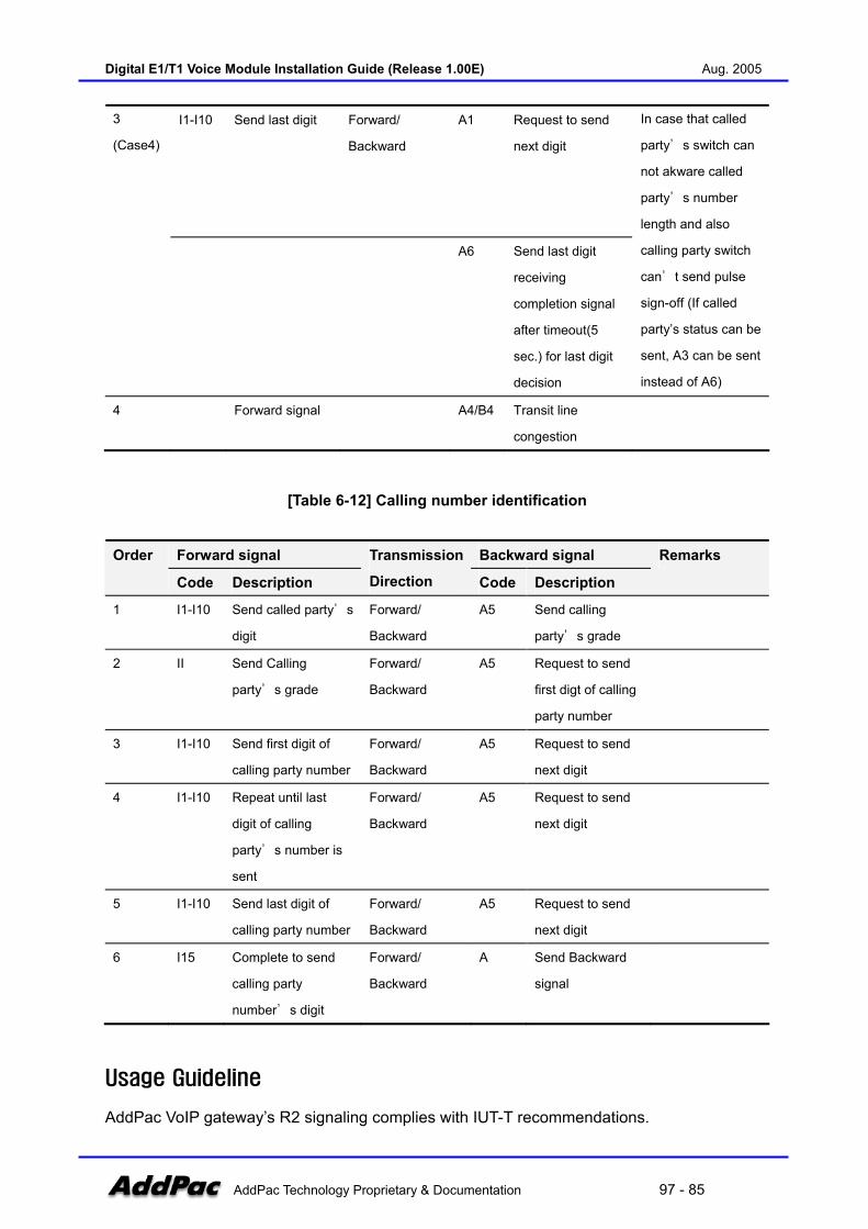
Digital E1/T1 Voice Module Installation Guide (Release 1.00E) Aug. 2005
AddPac Technology Proprietary & Documentation 97 - 85
I1-I10 Send last digit Forward/
Backward
A1 Request to send
next digit
3
(Case4)
A6 Send last digit
receiving
completion signal
after timeout(5
sec.) for last digit
decision
In case that called
party’s switch can
not akware called
party’s number
length and also
calling party switch
can’t send pulse
sign-off (If called
party’s status can be
sent, A3 can be sent
instead of A6)
4 Forward signal A4/B4 Transit line
congestion
[Table 6-12] Calling number identification
Forward signal Backward signal Order
Code Description
Transmission
Direction Code Description
Remarks
1 I1-I10 Send called party’s
digit
Forward/
Backward
A5 Send calling
party’s grade
2 II Send Calling
party’s grade
Forward/
Backward
A5 Request to send
first digt of calling
party number
3 I1-I10 Send first digit of
calling party number
Forward/
Backward
A5 Request to send
next digit
4 I1-I10 Repeat until last
digit of calling
party’s number is
sent
Forward/
Backward
A5 Request to send
next digit
5 I1-I10 Send last digit of
calling party number
Forward/
Backward
A5 Request to send
next digit
6 I15 Complete to send
calling party
number’s digit
Forward/
Backward
A Send Backward
signal
Usage Guideline
AddPac VoIP gateway’s R2 signaling complies with IUT-T recommendations.
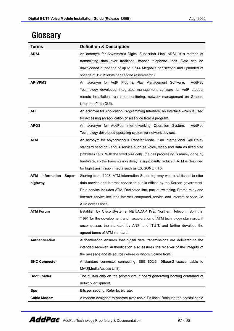
Digital E1/T1 Voice Module Installation Guide (Release 1.00E) Aug. 2005
AddPac Technology Proprietary & Documentation 97 - 86
Glossary
Terms Definition & Description ADSL An acronym for Asymmetric Digital Subscriber Line, ADSL is a method of
transmitting data over traditional copper telephone lines. Data can be
downloaded at speeds of up to 1.544 Megabits per second and uploaded at
speeds of 128 Kilobits per second (asymmetric).
AP-VPMS An acronym for VoIP Plug & Play Management Software. AddPac
Technology developed integrated management software for VoIP product
remote installation, real-time monitoring, network management on Graphic
User Interface (GUI).
API An acronym for Application Programming Interface, an Interface which is used
for accessing an application or a service from a program.
APOS An acronym for AddPac Internetworking Operation System, AddPac
Technology developed operating system for network devices.
ATM An acronym for Asynchronous Transfer Mode. It an International Cell Relay
standard sending various service such as voice, video and data as fixed size
(53bytes) cells. With the fixed size cells, the cell processing is mainly done by
hardware, so the transmission delay is significantly reduced. ATM is designed
for high transmission media such as E3, SONET, T3.
ATM Information Super-
highway
Starting from ‘1993, ATM information Super-highway was established to offer
data service and internet service to public offices by the Korean government.
Data service includes ATM, Dedicated line, packet switching, Frame relay and
Internet service includes Internet compound service and internet service via
ATM access lines.
ATM Forum Establish by Cisco Systems, NET/ADAPTIVE, Northern Telecom, Sprint in
‘1991 for the development and acceleration of ATM technology star nards. It
encompasses the standard by ANSI and ITU-T, and further develops the
agreed terms of ATM standard.
Authentication Authentication ensures that digital data transmissions are delivered to the
intended receiver. Authentication also assures the receiver of the integrity of
the message and its source (where or whom it came from).
BNC Connector A standard connector connecting IEEE 802.3 10Base-2 coaxial cable to
MAU(Media Access Unit).
Boot Loader The built-in chip on the printed circuit board generating booting command of
network equipment.
Bps Bits per second. Refer to: bit rate.
Cable Modem A modem designed to operate over cable TV lines. Because the coaxial cable

Digital E1/T1 Voice Module Installation Guide (Release 1.00E) Aug. 2005
AddPac Technology Proprietary & Documentation 97 - 87
used by cable TV provides much greater bandwidth than telephone lines, a
cable modem can be used to achieve more bandwidth. Cable network also
requires modularization and demutualization process while sending the data.
Call Center A call center is a central place where customer and other telephone calls are
handled by an organization, usually with some amount of computer
automation. Typically, a call center has the ability to handle a considerable
volume of calls at the same time, to screen calls and forward them to someone
qualified to handle them, and to log calls. Call centers are used by mail-order
catalog organizations, telemarketing companies, computer product help desks,
and any large organization that uses the telephone to sell or service products
and services.
Caller ID A feature that displays the name and/or number of the calling party on
the phone's display when an incoming call is received. Virtually all
digital phones - as well as many analog phones - have this capability.
While typically only the number is received, most phones will display the
name, if the number matches an entry in the phone's built-in phone
book.
Category 5 cabling unshielded twisted pair (UTP) cabling. An Ethernet network operating at 10
Mbits/second (10BASE-T) will often tolerate low quality cables, but at 100
Mbits/second (10BASE-Tx) the cable must be rated as Category 5, or Cat 5 or
Cat V, by the Electronic Industry Association (EIA).
CBR Constant Bit Rate. A data transmission that can be represented by a non-
varying, or continuous, stream of bits or cell payloads. Applications such as
voice circuits generate CBR traffic patterns. CBR is an ATM service type in
which the ATM network guarantees to meet the transmitter's bandwidth and
Quality of Service requirements
CES An acronym for Circuit Emulation Service. enables users to multiplex or to
concentrate multiple circuit emulation streams for voice and video with packet
data on a single, high-speed ATM link without a separate ATM access
multiplexer.
Checksum A computed value which is dependent upon the contents of a packet. This
value is sent along with the packet when it is transmitted. The receiving
system computes a new checksum based upon the received data and
compares this value with the one sent with the packet. If the two values are
the same, the receiver has a high degree of confidence that the data was
received correctly.
Coaxial cable A cable with a single inner conductor with foam insulation and braided shield.
There are two types of this cable; 50Ω cable for digital signaling process and

Digital E1/T1 Voice Module Installation Guide (Release 1.00E) Aug. 2005
AddPac Technology Proprietary & Documentation 97 - 88
75Ω cable for analog signal process and high speed digital signal process.
CODEC An acronym for COder-DECoder 1. Built-in circuit device for coding/decoding
of analog signal to bit stream with Pulse Code Modulation method. 2. DSP
software algorithm for compressing/ decompressing voice or audio signal
Console DTE interface whether the command is delivered to the host.
CoS Class of Service (CoS) is a way of managing traffic in a network by grouping
similar types of traffic (for example, e-mail, streaming video, voice, large
document file transfer) together and treating each type as a class with its own
level of service priority. Unlike Quality of Service (QoS) traffic management,
Class of Service technologies do not guarantee a level of service in terms of
bandwidth and delivery time; they offer a "best-effort."
Decryption The process of converting encrypted data back into its original form, so it can
be understood.
DHCP Dynamic Host Configuration Protocol. A protocol which allows a host to obtain
configuration information, such as its IP address and the default router from a
server. This simplifies network administration because the software keeps
track of IP addresses. With DHCP device can have a different IP address
every time it connects to the network
DNS Domain Name Server, an Internet service that translates domain names into
IP addresses.
DS-3 Digital signal level 3, A line capable of delivering 44.7 Mbps (44,700 Kbps) in
both directions
DSP Digital Signal Processor. Dedicated microprocessor for digital signal process.
DTMF Dual Tone Multi-Frequency. Using two types of voice-band tones for dialing.
E&M An acronym for recEive and transmit or ear and mouth. E&M interface uses
a RJ-48 telephone cable to connect remote calls from an IP network to PBX
trunk lines (tie lines) for local distribution. It is a signaling technique for two-
wire and four-wire telephone and trunk interfaces.
E1 The basic building block for European multi-megabit data rates, with a
bandwidth of 2.048Mbps.
Encryption the manipulation of a packet's data in order to prevent any but the intended
recipient from reading that data.
Ethernet Broadband LAN standard initiated by Xerox Corporation and co-developed by
Intel and DEC. Utilizing CSMA/CD and the various cables of 10Mbps are
used. It is similar to IEEE 802.3. Refer to: 10Base-2, 10Base5, 10Base-F,
10Base-T, 10Broad-36, Fast Ethernet, IEEE 802.3.
FAX Short for "FACSimile." In essence, a fax machine sends an electronic
"facsimile" or copy of the document. An optical scanner in the machine scans

Digital E1/T1 Voice Module Installation Guide (Release 1.00E) Aug. 2005
AddPac Technology Proprietary & Documentation 97 - 89
the document and the resulting bit stream is then sent to the receiving
machine via telephone line. The transmission and the reproduction at a
distance of still pictures printed matter and similar documented material
Frame data that is transmitted between network points as a unit complete with
addressing and necessary protocol control information. A frame is usually
transmitted serial bit by bit and contains a header field and a trailer field that
"frame" the data. (Some control frames contain no data.)
Frame-Relay Switching type Data Link Layer Protocol. Using HDLC capsule, process multi-
number of virtual circuits between devices.
FTP an acronym for File Transfer Protocol, a very common method of transferring
one or more files from one computer to another. Defined at RFC 959.
FXO Foreign Exchange Office. An FXO interface connects to the Public Switched
Telephone Network (PSTN) central office and is the interface offered on a
standard telephone.
FXS Foreign Exchange Station. An FXS interface connects directly to a standard
telephone and supplies ring, voltage, and dial tone.
G.711 Describes the 64-kbps PCM voice coding technique. In G.711, encoded voice
is already in the correct format for digital voice delivery in the PSTN or through
PBXs.
G.723.1 Describes a compression technique that can be used for compressing speech
or audio signal components at a very low bit rate as part of the H.324 family of
standards. This CODEC has two bit rates associated with it: 5.3 and 6.3 kbps.
The higher bit rate is based on ML-MLQ technology and provides a somewhat
higher quality of sound. The lower bit rate is based on CELP and provides
system designers with additional flexibility.
G.726 Describes ADPCM coding at 40, 32, 24 and 16 kbps. ADPCM encoded voice
can be interchanged between packet voice, PSTN, and PBX networks if the
PBX networks are configured to support ADPCM. Described in the ITU-T
standard in its G-series recommendations.
G.728 Describes a 16 kbps low-delay variation of CELP voice compression. CELP
voice coding must be translated into a public telephony format for delivery to
or through the PSTN. Described in the ITU-T standard in its G-series
recommendations..
Gatekeeper The component of an H.323 conferencing system that performs call address
resolution, admission control, and subnet bandwidth management. H.323
entity on a LAN that provides address translation and control access to the
LAN for H.323 terminals and gateways. The gatekeeper can provide other
services to the H.323 terminals and gateways, such as bandwidth
Digital E1/T1 Voice Module Installation Guide (Release 1.00E) Aug. 2005
AddPac Technology Proprietary & Documentation 97 - 90
management and locating gateways. A gatekeeper maintains a registry of
devices in the multimedia network. The devices register with the gatekeeper at
startup and request admission to a call from the gatekeeper.
H.225 An International Telecommunication Union (ITU-T) standard for H.225.0
session control and packetization. It defines various protocols of RAS,
Q.931, RTP and etc.
H.245 An International Telecommunication Union (ITU-T) standard for H.245 end-
point control.
H.323 An International Telecommunication Union (ITU-T) standard that describes
packet-based video, audio, and data conferencing.
HBD3 Line code type of E1 line.
HDLC An acronym for High-Level Data Link Control. A transmission protocol for the
Data Link Layer. In HDLC, data is organized into a unit (called a frame) and
sent across a network to a destination that verifies its successful arrival.
Variations of HDLC are also used for the public networks that use the X.25
communications protocol and for frame relay, a protocol used in both and wide
area network, public and private.
Hookflash Short on-hook period usually generated by a telephone-like device during a
call to indicate that the telephone is attempting to perform a dial-tone recall
from a PBX. Hookflash is often used to perform call transfer.
HTTP An acronym for Hypertext Transfer Protocol. A file transfer protocol used by
web browser or web server for transmitting text or graphic files.
IPSec Internet Protocol Security protocol, a framework for a set of protocols for
security at the network or packet processing layer of network communication.
Earlier security approaches have inserted security at the Application layer of
the communications model. IPsec is said to be especially useful for
implementing virtual private networks and for remote user access through dial-
up connection to private networks. A big advantage of IPsec is that security
arrangements can be handled without requiring changes to individual user
computers. Cisco has been a leader in proposing IPsec as a standard (or
combination of standards and technologies) and has included support for it in
its network routers.
IPv6 IPv6 (Internet Protocol Version 6) is the latest level of the Internet Protocol (IP)
and is now included as part of IP support in many products including the major
computer operating systems. IPv6 has also been called "IPng" (IP Next
Generation). Formally, IPv6 is a set of specifications from the Internet
Engineering Task Force (IETF). IPv6 was designed as an evolutionary set of
improvements to the current IP Version 4. Network hosts and intermediate
Digital E1/T1 Voice Module Installation Guide (Release 1.00E) Aug. 2005
AddPac Technology Proprietary & Documentation 97 - 91
nodes with either IPv4 or IPv6 can handle packets formatted for either level of
the Internet Protocol. Users and service providers can update to IPv6
independently without having to coordinate with each other.
ISP An ISP (Internet service provider) is a company that provides individuals and
other companies access to the Internet and other related services such as
Web site building and virtual hosting. An ISP has the equipment and the
telecommunication line access required to have a point-of-presence on the
Internet for the geographic area served. The larger ISPs have their own high-
speed leased lines so that they are less dependent on the telecommunication
providers and can provide better service to their customers. Among the largest
national and regional ISPs are AT&T WorldNet, IBM Global Network, MCI,
Netcom, UUNet, and PSINet.
ITU-T The ITU-T (for Telecommunication Standardization Sector of the International
Telecommunications Union) is the primary international body for fostering
cooperative standards for telecommunications equipment and systems. It was
formerly known as the CCITT. It is located in Geneva, Switzerland
IVR Interactive Voice Response (IVR) is a software application that accepts a
combination of voice telephone input and touch-tone keypad selection and
provides appropriate responses in the form of voice, fax, callback, e-mail and
perhaps other media. IVR is usually part of a larger application that includes
database access. Common IVR applications include: Bank and stock account
balances and transfers.
LAN A local area network is a group of computers and associated devices that
share a common communications line and typically share the resources of a
single processor or server within a small geographic area (for example, within
an office building). LAN standard defines cable connection and signal
processing on Physical Layer and Data Link Layer.
Link Network communication channels consisting of sending and receiving devices,
circuits, transmission path. Usually refer to WAN connection. Referred as
Line, or transmission link.
Loopback test A loopback test is a test in which a signal in sent from a communications
device and returned (looped back) to it as a way to determine whether the
device is working right or as a way to pin down a failing node in a network.
MAC Address Standardized data link layer address that is required for every port or device
that connects to a LAN. Other devices in the network use these addresses to
locate specific ports in the network and to create and update routing tables
and data structures. MAC addresses are 6 bytes long and are controlled by
the IEEE. Also known as a hardware address, MAC-layer address, and
Digital E1/T1 Voice Module Installation Guide (Release 1.00E) Aug. 2005
AddPac Technology Proprietary & Documentation 97 - 92
physical address. Compare with network address.
MAN A data network designed for a town or city. MANs are considered
larger than LANs but smaller than WANs. Compare with: LAN, WAN.
MGCP MGCP, also known as H.248 and Megaco, is a standard protocol for
handling the signaling and session management needed during a
multimedia conference. The protocol defines a means of
communication between a media gateway, which converts data from
the format required for a circuit-switched network to that required for a
packet-switched network and the media gateway controller. MGCP
can be used to set up, maintain, and terminate calls between multiple
endpoints. Megaco and H.248 refer to an enhanced version of MGCP
NAT NAT (Network Address Translation) is the translation of an Internet Protocol
address (IP address) used within one network to a different IP address known
within another network. One network is designated the inside network and the
other is the outside.
NTP Network Time Protocol (NTP) is a protocol that is used to synchronize
computer clock times in a network of computers. In common with similar
protocols, NTP uses Coordinated Universal Time (UTC) to synchronize
computer clock times to a millisecond, and sometimes to a fraction of a
millisecond.
PABX Private Automatic Branch Exchange. A telephone switch for use inside a
corporation. It connects offices (internal extensions) with each other and
provides access (typically by dialing an access number such as 9) to the
public telephone network PABX is the preferred term in Europe, PBX is used
in the USA.
Packet Packets contain a source and destination address as well as the actual
message. Packets also known as Datagrams.
PBX A PBX (private branch exchange) is a telephone system within an enterprise
that switches calls between enterprise users on local lines while allowing all
users to share a certain number of external phone lines.
PING Packet INternet Groper, a packet (small message) sent to test the validity /
availability of an IP address on a network
Point to Point Connection Basic connection type. In ATM, point to point connection is half duplex
connection between two ATM end systems or full duplex connection.
Pont to Multipoint
Connection
Basic connection type. In ATM, point to multipoint connection is half duplex
connection among one sending end system (root node) and multiple receiving
end system. Compare with: point-to-point connection.
POTS Plain Old Telephone Service. Compare with: PSTN.
Digital E1/T1 Voice Module Installation Guide (Release 1.00E) Aug. 2005
AddPac Technology Proprietary & Documentation 97 - 93
PPP The most popular method for transporting IP packets over a serial link
between the user and the ISP. Developed in 1994 by the IETF and
superseding the SLIP protocol, PPP establishes the session between the
user's computer and the ISP using its own Link Control Protocol (LCP). PPP
supports PAP, CHAP and other authentication protocols as well as
compression and encryption.
Protocol Stack Any set of communication protocols, such as TCP/IP, that consists of two or
more layers of software and hardware. It's called a stack because each layer
builds on the functionality in the layer below
PSTN Public Switched Telephone Network – term for the entire, world-wide
telephone network. Sometimes refers to as POTS.
PVC Permanent Virtual Circuit or permanent virtual connection. A continuously
available communications path that connects two fixed end points.
Q.931 Signaling ITU-T specification for network layer of ISDN. Q.931 uses out-of-band
signaling on the D-channel to control calls.
QoS This refers to the assumption that data transmission rates, error rates, and
other characteristics can be measured, improved, and to some degree,
guaranteed in advance. Basically, QoS describes a collective measure of the
level of service a provider delivers to its customers or subscribers.
RAM Random-Access Memory, a non-retentive memory, whose contents get lost
after a switch-off or reset. Application programs run in the random access
memory and data is stored and processed.
RAS Registration Admission Status protocol. The communication protocol used to
convey registration, admission and status messages between H.323 endpoints
and the gatekeeper.
RISC Reduced Instruction Set Computing
Router On the Internet, a router is a device or, in some cases, software in a computer,
that determines the next network point to which a packet should be forwarded
toward its destination. The router is connected to at least two networks and
decides which way to send each information packet based on its current
understanding of the state of the networks it is connected to. A router is
located at any gateway (where one network meets another), including each
Internet point-of-presence. A router is often included as part of a network
switch. Compare with: gateway. Refer to: relay.
RS-232 Most common Physical Layer interface. Known as EIA/TIA-232.
RTCP Real-time Control Protocol (RTCP) is a companion protocol of RTP that is
used to maintain quality of service. Refer to: RTP(Real-Time Transport
Protocol).

Digital E1/T1 Voice Module Installation Guide (Release 1.00E) Aug. 2005
AddPac Technology Proprietary & Documentation 97 - 94
RTP 1. Routing Table Protocol, VINES routing protocol based on RIP. Distributes
network topology, and aids VINES servers in finding neighboring clients,
servers, and routers. Uses delay as a routing metric. Refer to: SRTP.
2. Rapid Transport Protocol. Provides pacing and error recovery for APPN
data as it crosses the APPN network. With RTP, error recovery and flow
control are done end-to-end rather than at every node. RTP prevents
congestion rather than reacts to it.
3. Real-Time Transport Protocol. Commonly used with IP networks. RTP is
designed to provide end-to-end network transport functions for applications
transmitting real-time data, such as audio, video, or simulation data, over
multicast or unicast network services. RTP provides such services as payload
type identification, sequence numbering, time-stamping, and delivery
monitoring to real-time applications.
SIP The Session Initiation Protocol (SIP) is an Internet Engineering Task Force
(IETF) standard protocol for initiating an interactive user session that involves
multimedia elements such as video, voice, chat, gaming, and virtual reality.
Like HTTP or SMTP, SIP works in the Application layer of the Open Systems
Interconnection (OSI) communications model. The Application layer is the
level responsible for ensuring that communication is possible. SIP can
establish multimedia sessions or Internet telephony calls, and modify, or
terminate them. The protocol can also invite participants to unicast or multicast
sessions that do not necessarily involve the initiator. Because the SIP supports
name mapping and redirection services, it makes it possible for users to
initiate and receive communications and services from any location, and for
networks to identify the users whatever they are. SIP is a request-response
protocol, dealing with requests from clients and responses from servers.
Participants are identified by SIP URLs. Requests can be sent through any
transport protocol, such as UDP, SCTP, or TCP. SIP determines the end
system to be used for the session, the communication media and media
parameters, and the called party's desire to engage in the communication.
Once these are assured, SIP establishes call parameters at either end of the
communication, and handles call transfer and termination. The Session
Initiation Protocol is specified in IETF Request for Comments [RFC] 2543.
SmartViewer The real-time monitoring, statistical data search and management GUI based
software developed by AddPac Technology for AP-GK1000, AP-GK2000, AP-
GK3000 models.
SNMP Simple Network Management Protocol. Network management protocol used
almost exclusively in TCP/IP networks. SNMP provides a means to monitor

Digital E1/T1 Voice Module Installation Guide (Release 1.00E) Aug. 2005
AddPac Technology Proprietary & Documentation 97 - 95
and control network devices, and to manage configurations, statistics
collection, performance, and security. Refer to: SGMP, SNMP2.
T1 A TDM physical transmission standard consisting of two twisted wire pairs and
related equipment capable of carrying a 1.544 Mbps DS-1 signal. Term often
used interchangeably with DS-1. Refer to: AMI, B8ZS, DS-1.
TCP/IP Transmission Control Protocol/Internet Protocol, The protocol suit developed
by DoD (USA) in 1970s for the worldwide inter-network development. TCP &
IP is the most well known protocols of the suite. Refer to: IP, TCAP.
Telco Telephone Company, referring to the company offering telephone service to
customers. Typically, it refers to an individual company such as Bell
operating company offering local telephone service, however, sometimes local
telephony service providers are included.
Telnet Standard Terminal Emulation program covered by TCP/IP protocol stack. Used
for remote terminal connection. Via Telnet, users can log-in to the system
and operate the resources as working on the local system. Defined on RFC
854.
VCI the address or label of a VC; a value stored in a field in the ATM cell header
that identifies an individual virtual channel to which the cell belongs. VCI
values may be different for each data link hop of an ATM virtual connection.
VDSL New DSL technology that accepts bandwidths of up to 27 Mbps over relatively
short distances. VDSL, in the process of being standardized, allows symmetric
or asymmetric throughputs that are much higher than other xDSL standards
(up to 27 Mbps when downloading and 3 Mbps when uploading under
asymmetric or 14 Mbps in symmetric), as well as the simultaneous transport of
ISDN (Numeris) services but with much shorter ranges that do not exceed 900
m to 1 km. In practice, this technique may require the deployment of optical
remotes and the setting up of active equipment in the local loop. Compare
with: ADSL, HDSL, SDSL.
VoATM Voice Over ATM. Voice over ATM enables an ATM switch to carry voice traffic
(for example, telephone calls and faxes) over an ATM network. When sending
voice traffic over ATM, the voice traffic is encapsulated using AAL1/AAL2 ATM
packets.
VoFR Voice Over Frame Relay. Voice over Frame Relay enables a router to carry
voice traffic (for example, telephone calls and faxes) over a Frame Relay
network. When sending voice traffic over Frame Relay, the voice traffic is
segmented and encapsulated for transit across the Frame Relay network
using FRF.12 encapsulation.
VoHDLC Voice Over HDLC. Voice over HDLC enables a router to carry live voice traffic
Digital E1/T1 Voice Module Installation Guide (Release 1.00E) Aug. 2005
AddPac Technology Proprietary & Documentation 97 - 96
(for example, telephone calls and faxes) back-to-back to a second router over
a serial line.
VoIP VoIP (Voice delivered using the Internet Protocol) is a term used in IP
telephony for a set of facilities for managing the delivery of voice information
using the Internet Protocol (IP). In general, this means sending voice
information in digital form in discrete packets rather than in the traditional
circuit-committed protocols of the public switched telephone network (PSTN).
A major advantage of VoIP and Internet telephony is that it avoids the tolls
charged by ordinary telephone service.
VPN Virtual Private Network, VPN allows IP traffic to travel securely over a public
TCP/IP network by encrypting all traffic from one network to another. A VPN
uses "tunneling" to encrypt all information at the IP level.
WAN A network that covers a large geographical area. Typical WAN technologies
include point-to-point, X.25 and frame relay. Compare with: LAN, MAN.
#####

Digital E1/T1 Voice Module Installation Guide (Release 1.00E) Aug. 2005
AddPac Technology Proprietary & Documentation 97 - 97
AddPac Technology Co., Ltd.2F & 3F, Jeong-Am Bldg., 769-12 Yeoksam-dong, Gangnam-gu, Seoul, 135-080, Korea
Tel: +82 2 568 3848 Fax: +82 2 568 3847
Email: [email protected]:// www.addpac.com