ADDITIVE MANUFACTURING WITH COMPOSITES FOR … · 2.1 Additive Manufacturing Additive Manufacturing...
15
SAMPE 2016, Long Beach, CA, USA, May 23 rd – 26 th , 2016 ADDITIVE MANUFACTURING WITH COMPOSITES FOR INTEGRATED AIRCRAFT STRUCTURES Daniel-Alexander Türk 1 , Ralph Kussmaul 2 , Markus Zogg 2 , Christoph Klahn 2 , Adriaan Spierings 2 , Holger Könen 3 , Paolo Ermanni 1 , Mirko Meboldt 1 1 ETH Zürich Leonhardstr. 21 Zürich 8092, Switzerland 2 inspire AG Technoparkstr. 1 Zürich 8005, Switzerland 3 RUAG Schweiz AG Seetalstrasse 175 Emmen 6032, Switzerland ABSTRACT The combination of additive manufacturing (AM) with advanced composites unlocks potentials in the design and development of highly integrated lightweight structures. This paper investigates two design potentials where the combination of AM and carbon fiber prepreg technology is applied to honeycomb sandwich structures: (i) Reduction of number of parts: The use of selective laser sintered cores allows the integration of various functions into one single part. These include structural as well as tooling, positioning and assembly functions. (ii) Tailored mechanical performance: With AM it is possible to adapt the mechanical properties of the core according to local load requirements. These potentials are demonstrated using the example of the development of an aircraft instrument panel. The approach of combining AM with advanced composites is evaluated by assessing the weight and the number of parts for the demonstrator panel compared to a state-of-the-art aluminum machined instrument panel. Weight savings of 40 % and parts reduction by 50 % indicate that the technology is competitive for complex low volume parts. 1. INTRODUCTION Differential design and integral design are two major engineering approaches in lightweight design, that ultimately decide on the system’s lightweight efficiency [1]. Both approaches differ fundamentally in the following two aspects: First, structural complexity, that includes but is not limited to the capability of producing geometrically complex structures. Second, the degree of integration, that is the reduction of joining interfaces necessary for the assembly of the structure. Figure 1 maps both approaches according to these characteristics. Differential design is a classic design approach where single structural elements are joined additively. In aerospace industry Türk, D. ([email protected]) & Kussmaul, R. ([email protected]) 1
Transcript of ADDITIVE MANUFACTURING WITH COMPOSITES FOR … · 2.1 Additive Manufacturing Additive Manufacturing...

SAMPE 2016, Long Beach, CA, USA, May 23rd – 26th, 2016
ADDITIVE MANUFACTURING WITH COMPOSITES FOR INTEGRATED AIRCRAFT STRUCTURES
Daniel-Alexander Türk1, Ralph Kussmaul2, Markus Zogg2, Christoph Klahn2, Adriaan Spierings2, Holger Könen3, Paolo Ermanni1, Mirko Meboldt1
1ETH Zürich
Leonhardstr. 21 Zürich 8092, Switzerland
2inspire AG Technoparkstr. 1
Zürich 8005, Switzerland
3RUAG Schweiz AG Seetalstrasse 175
Emmen 6032, Switzerland
ABSTRACT
The combination of additive manufacturing (AM) with advanced composites unlocks potentials in the design and development of highly integrated lightweight structures. This paper investigates two design potentials where the combination of AM and carbon fiber prepreg technology is applied to honeycomb sandwich structures: (i) Reduction of number of parts: The use of selective laser sintered cores allows the integration of various functions into one single part. These include structural as well as tooling, positioning and assembly functions. (ii) Tailored mechanical performance: With AM it is possible to adapt the mechanical properties of the core according to local load requirements. These potentials are demonstrated using the example of the development of an aircraft instrument panel. The approach of combining AM with advanced composites is evaluated by assessing the weight and the number of parts for the demonstrator panel compared to a state-of-the-art aluminum machined instrument panel. Weight savings of 40 % and parts reduction by 50 % indicate that the technology is competitive for complex low volume parts.
1. INTRODUCTION Differential design and integral design are two major engineering approaches in lightweight design, that ultimately decide on the system’s lightweight efficiency [1]. Both approaches differ fundamentally in the following two aspects: First, structural complexity, that includes but is not limited to the capability of producing geometrically complex structures. Second, the degree of integration, that is the reduction of joining interfaces necessary for the assembly of the structure. Figure 1 maps both approaches according to these characteristics. Differential design is a classic design approach where single structural elements are joined additively. In aerospace industry
Türk, D. ([email protected]) & Kussmaul, R. ([email protected]) 1

SAMPE 2016, Long Beach, CA, USA, May 23rd – 26th, 2016
typical designs are conducted with machined sheet metal parts that are assembled with rivets and rivet nuts. On one hand, this approach allows the manufacturing of parts with high structural complexity. On the other hand, differential designs show a high number of parts (e.g. joints) that accumulate weight. In contrast, integral design pursues a maximum reduction of single parts forming the structure. An integral design avoids extensive and heavy joints, thereby reducing the total weight and the number of assembly steps. However, the structural complexity of integral designs is limited. This is mainly due to manufacturing constraints. E.g. in metal design the machinability (accessibility for milling tools) must be ensured.
Figure 1. Lightweight construction approaches In composites, there are two major strategies to achieve integral designs: co-curing and sandwich designs. In a co-curing process uncured composite adherends (e.g. composite skin and stringers) are cured together in one process step forming one integral part. Co-curing eliminates additional processing steps and reduces the number of parts [2]. However, integral composites manufacturing requires complex tooling to fulfil three main functions: positioning and shaping of the uncured reinforcement textile to its part geometry and fixation of inserts. This leads to the first challenge: Tooling for complex integral composite parts is very costly when made with conventional (machining) technologies. Composite sandwich designs consist of fiber-reinforced polymers (FRP) face sheets that enclose a lightweight honeycomb or foam core. Typically, the sandwich core is a full length continuous element and substitutes a high number of ribs and spars necessary in differential designs. To overcome local stress peaks in load introduction areas, at corners and joints, particular considerations are necessary. The integration of load introduction elements requires extensive additional processing steps such as machining, local filling the core with a potting compound, insertion of the insert and post processing [3]. This leads to the second challenge: The integration of functions into state-of-the-art sandwich designs is costly and effortful. Both challenges imply a need for increased geometric freedom and easy integration of functions into sandwich cores. Additive Manufacturing (AM) technologies, colloquially called 3D printing, seem to fulfil these needs, as they allow the direct production of parts with extremely high geometric complexity. Therefrom follows the possibility of integrating various functions within one part. The combination of additive manufacturing with advanced composites (CFRP) offers potentials in the design of integrated lightweight parts with high structural complexity. The present authors recently proposed load introduction elements and inner tooling as two design potentials for the combination of AM with CFRP. Load introduction elements are made with Selective Laser
Türk, D. ([email protected]) & Kussmaul, R. ([email protected]) 2
SAMPE 2016, Long Beach, CA, USA, May 23rd – 26th, 2016
Melting (SLM). This powder bed fusion process produces objects using lasers to selectively melt metal powder layer by layer. [4]. The trade journal Composites World states that 3D printing of aerospace tooling is a growing trend [5]. The authors mention applications as master models, layup tools used to produce composite parts for autoclave processes, washout mandrels for trapped tooling, as well as holding fixtures. Riss et al. optimized a structural honeycomb core made by additive manufacturing that has integrated functions such as threads and bearing carriers [6]. Kausch investigated a combined processing route where a cured CFRP plate was inserted in an interrupted SLM process to form an integral hybrid manifold [7]. In this paper, we investigate how the combination of additive manufacturing with advanced composites can lead to innovative integral lightweight designs with increased complexity. The following two design principles are proposed where the use of AM influences either the lightweight properties or the manufacturing effort of the AM-CFRP part. First, selective laser sintered (SLS) honeycomb cores with integrated positioning and fixation elements reduce the number of parts and therefore the number of assembly steps. Second, AM allows to tailor the mechanical properties according to local loads. This paper proceeds as follows: Section 2 provides background information about SLM and SLS, the two additive manufacturing technologies relevant in this research. Furthermore, the novel manufacturing route using autoclave prepregs, a co-curing process and inserting complex elements made by AM is illustrated. Section 3 introduces three design principles and their areas of impact. In Section 4 the design principles are demonstrated by using the example of the development of an aircraft instrument panel. Section 5 evaluates the novel approach by assessing the weight, the number of parts and the number of assembly steps for the demonstrator panel compared to a state-of-the-art aluminum machined instrument panel. Section 6 concludes.
2. BACKGROUND INFORMATION 2.1 Additive Manufacturing Additive Manufacturing is a process of joining materials to make objects from 3D model data, usually layer upon layer, as opposed to subtractive manufacturing methodologies [8]. AM technologies have reached a manufacturing readiness level ranging from 5 to 10, depending on the application. For aerospace, production is demonstrated in a production environment (TRL7) and for tooling, low rate production is state of the art [9]. Amongst others, material powder based fusion processes such as Selective Laser Melting (SLM) and Selective Laser Sintering (SLS) are applicable for high performance functional parts. SLM and SLS have in common that a laser beam is directed onto the powder bed in such way that it thermally melts, respectively fuses the powder material to form the slice of the parts’ cross-section [10]. This leads to the consolidation of the powder particles in the scanned area, resulting in a nearly fully dense layer of the part being built. The building platform is lowered and the process is repeated until the final physical part is produced. SLM typically uses metal powders to generate parts, whereas the most common material used in SLS is polyamide 12. The high amount of energy required to melt metal powder leads to residual stresses. To overcome distortions, manufacturers attach the part to a base plate and add support structures for some inclined geometries. Further design guidelines can be found in [11, 12]. These design restrictions do not exist for parts made with SLS since the energy amount required to sinter plastic powders is much lower.
Türk, D. ([email protected]) & Kussmaul, R. ([email protected]) 3
SAMPE 2016, Long Beach, CA, USA, May 23rd – 26th, 2016
2.2 Advanced Composites Composites are multi-phase materials. They result from the combination of two or more constituent materials with different properties to form a fully new material [13]. Carbon Fiber Reinforced Polymers (CFRP) consist of aligned continuous carbon fibers reinforcements that are embedded in a polymeric resin (e.g. epoxy). For many high performance applications PREimPREGnated (prepreg) fibers are used. Prepregs are resin-impragnated semifinished products in fiber, fabric or mat form, in which the resin is kept in a non-polymerized state through cooling. Semifinished products with fibers laid at 0° orientation are called unidirectional (UD). UD materials provide the ability to tailor the composite properties in a desired direction. Woven fabric prepregs are used to make contoured parts. Prepregs common in industry are based on epoxy resins [14]. The autoclave process is the state-of-the-art manufacturing technique for high performance industrial applications. In this process prepregs are cut and laid down in the desired fiber orientation on a tool. The layup is vacuum bagged and put in an autoclave where defined temperatures ranging up to 180°C and pressures up to 10 bar are applied for curing and consolidation of the part. The prepreg layup process is labor intensive but shows great flexibility in design and therefore is suited for low volume production [15]. In the co-curing sandwich manufacturing process no additional adhesive film but only the resin of the prepreg is used to generate skin-core bonding, thus reducing the number of joints and process steps.
2.3 General Manufacturing Process Route: Co-Cured Autoclave Prepregs The manufacturing technique applied in this research is a co-curing autoclave process. The novelty in the process is the insertion of complex elements made by additive manufacturing during the prepreg layup. This combination allows the manufacturing of complex integral parts. The general manufacturing concept is shown in Figure 2 and the detailed steps are now described: (i) Preparation: The tooling consists of a CFRP base plate. Metal blocks which are positioned by pins act as support and are screwed to the tooling plate. Cleaning agents and release agents are applied on the tool and the metal supports. The prepreg is removed from the refrigerator, thawed and cut in the desired orientation to near-net shape. (ii) Layup: First, the prepreg plies are draped on the tooling. Then, elements made by AM are positioned on the prepreg and, if required by design, pinned to the metal support. Those are the sandwich cores elements made by SLS and the SLM inserts. The SLS core elements are split for the production of parts that exceed the building space of the respective SLS machine. The SLS core elements are subsequently laid down and assembled. The remaining prepreg sheets are placed on the core. (iii) Bagging: A vacuum bagging is conducted. This includes the application of a release film, bleeder and the covering with a vacuum bag. The entire assembly is placed in the autoclave. (iv) Curing & Consolidation: The composite is co-cured and consolidated in one shot according to the cure cycle data of the resin system in a standard autoclave process. (v) Demolding & Postprocessing: After cooling, the bagging is removed and the part is taken out of the tool. Subsequently, the part is milled to its final shape. Pockets for plugs etc. are milled and holes are drilled. Finally, surface finish is applied.
Türk, D. ([email protected]) & Kussmaul, R. ([email protected]) 4

SAMPE 2016, Long Beach, CA, USA, May 23rd – 26th, 2016
Figure 2. Manufacturing concept combining CFRP and additive manufacturing
3. MAJOR DESIGN PRINCIPLES This chapter introduces two major design principles that are (i) integrated positioning and fixation elements and (ii) tailored mechanical properties. These design principles promise benefits in design and manufacturing of highly integrated composite structures. They are based on two fundamental characteristics of additive manufacturing: The first one is the possibility to design very complex geometries, often referred to as complexity for free. From this follows the second advantage, that is the integration of various functions into one single part.
3.1 Integrated Positioning and Fixation Elements: Plug and Play Composites manufacturing is an additive process as reinforcement plies, inserts, and sandwich core elements are subsequently added to form the part. Draping prepreg as well as positioning and fixation of inserts during the manufacturing process is crucial to meet design tolerances for the attachment of further components (e.g. instruments) or load introductions. Positioning and fixation of inserts into conventional honeycomb structures is effortful and requires many process steps. To install a molded-in fastener a hole is drilled into the honeycomb panel. Potting resin is applied to flow underneath the insert. The insert is placed in the drilled hole and a temporary tab is used to hold and fix the fastener during the potting process [16].
Figure 3. Integrated positioning and fixation elements in an additive honeycomb core
Türk, D. ([email protected]) & Kussmaul, R. ([email protected]) 5

SAMPE 2016, Long Beach, CA, USA, May 23rd – 26th, 2016
Additive Manufacturing allows the integration of such positioning and fixation elements in the core structure. Figure 3 shows a honeycomb element made by SLS. It features various pockets to integrate metal inserts. The throughout insert (1 in Figure 3) is positioned and fixed through the pocket in the additive honeycomb. Bonding of the inserts to the face sheets is done by excessive resin of the prepreg facings. A further possibility is the integration of snap-in joints as a fundamental part of the design (2 in Figure 3). Snap-in connections are very common since their assembly is one of the quickest, cheapest and easiest to handle [17]. This plug & play approach reduces the assembly effort as each insert is simply placed into the corresponding pocket or connection element. The structure is preassembled before autoclave curing and the effort for integration is shifted away from post-fabrication. Furthermore, AM allows to shift shape complexity from external to integrated tooling. This principle can be seen in (3) of Figure 3 where a tooling for a support strap directly emerges from the honeycomb. The tooling not only takes over a shaping function for the prepreg but also guarantees smooth transitions of the load into the strap.
3.2 Tailored Mechanical Performance In conventional design the whole structure is dimensioned for the most heavily loaded point and the design is not adapted in less loaded areas. Some areas are therefore over-dimensioned and not weight-optimal. With AM it is easily possible to add or remove material and thereby to tailor the mechanical properties of the part according to local loads. This principle is illustrated using the example of an additive honeycomb core. Figure 4 shows a respective core made with SLS. It features a constant cell geometry in areas with similar loads whereas the cells are filled to become a full dense core in areas with high local stress concentrations. These areas are for example corners or webs with reduced widths. Furthermore it is possible to vary the height of the core while keeping the overall sandwich thickness constant. This is relevant for doublers, i.e. reinforcement patches that are put into or on a sandwich panel in highly stressed areas. A doubler should distribute high local forces over a larger area as gradually as possible [16]. The pocket necessary for internal doublers can be included during the design of the AM core element and manufactured directly without having to machine the honeycomb as can be seen in Figure 4, right.
Figure 4. SLS core (left) and patch placement (right)
Türk, D. ([email protected]) & Kussmaul, R. ([email protected]) 6

SAMPE 2016, Long Beach, CA, USA, May 23rd – 26th, 2016
4. EXPERIMENTATION In this section the design principles emerging from the combination of AM and CFRP are highlighted by the example of an aircraft instrument panel. First, the reference panel is introduced. Second, the development of an innovative aircraft instrument panel made by the combination of additive manufacturing with CFRP is presented.
4.1 Reference: an Aluminum Aircraft Instrument Panel The selected reference is a state-of-the-art instrument panel for a small multi-purpose aircraft that is produced in low volume. It is connected to the aircraft fuselage and is part of the cockpit. Its main function is the attachment of various instruments ranging from radio equipment to GPS. The structural concept is shown in Figure 5 and consists of a differential sheet metal design. All parts are made from aluminum. The overall dimensions are 900 x 300 x 300 mm. The panel features a total number of 49 interface points for the attachment of instruments and housings for plugs. The base plate is integrally machined down to a thickness of 3.2 mm. Two support straps are riveted to the webs of the base plate requiring eight additional interface points. The panel therefore consists of three sheet metal parts and 115 joining elements, resulting in 118 parts. The joining elements can be classified into rivets, rivet nuts and turn-lock DZUS fasteners. The total structural weight (without instruments) amounts to 1481 g, where over 98 % account for the sheet metal parts.
Figure 5. Reference aircraft instrument panel
Türk, D. ([email protected]) & Kussmaul, R. ([email protected]) 7

SAMPE 2016, Long Beach, CA, USA, May 23rd – 26th, 2016
4.2 Concept and Development of the AM-CFRP Sandwich Panel 4.2.1 Concept A novel aircraft instrument panel is developed using additive manufacturing and autoclave prepregs. The combined approach is used in a way to benefit from the specific advantages of each material and production technology, resulting in a highly integrated lightweight structure as shown in Figure 6. The mechanical concept is a sandwich design, where CFRP prepregs constitute the face sheets. The core consists of multifunctional honeycombs made by selective laser sintering in areas with need for the integration of functions. These functions are interface points for the attachment of instruments or plugs, complex geometries, sealing or edge damming during manufacturing. In areas where the only function is of structural nature, conventional aramid honeycomb C2-3.2-29-8 mm is used. Load introduction elements are made of stainless steel 1.4404 with SLM and are inserted into the multifunctional printed core. Since the part dimensions exceed the SLS building space, the SLS core elements are split into eight pieces. The total sandwich height is 10 mm, with 8 mm core height and 1 mm for each facing.
Figure 6. Aircraft instrument panel made by combining additive manufacturing and advanced composites
4.2.2 Stress analysis The stress analysis of the instrument panel is dedicated to emergency landing situations, in which high inertial loads occur. These inertial loads are mainly caused by the heavy instruments, which are attached to the panel. For reasons of passenger safety, structural failure of the panel must be ruled out.
Türk, D. ([email protected]) & Kussmaul, R. ([email protected]) 8

SAMPE 2016, Long Beach, CA, USA, May 23rd – 26th, 2016
4.2.2.1 Loads The certification basis is the CS-23 for Normal, Utility, Aerobatic, and Commuter Category Aeroplanes, Amendment 3. CS 23.561 General (b) (3) “Emergency landing conditions” defines the following ultimate load factors:
Table 1. Loads [18]
Direction Acceleration
upward 3.0 g
sideward 4.5 g
forward 18.0 g
downward 6.0 g
4.2.2.2 Material allowables The maximum material allowables for the CFRP UD prepreg are as follows:
Table 2. Material allowable for the CFRP UD prepreg The maximum material allowable for the steel is as follows:
Table 3. Material allowable for the steel
Parameter Value Unit Tensile strength 650 MPa
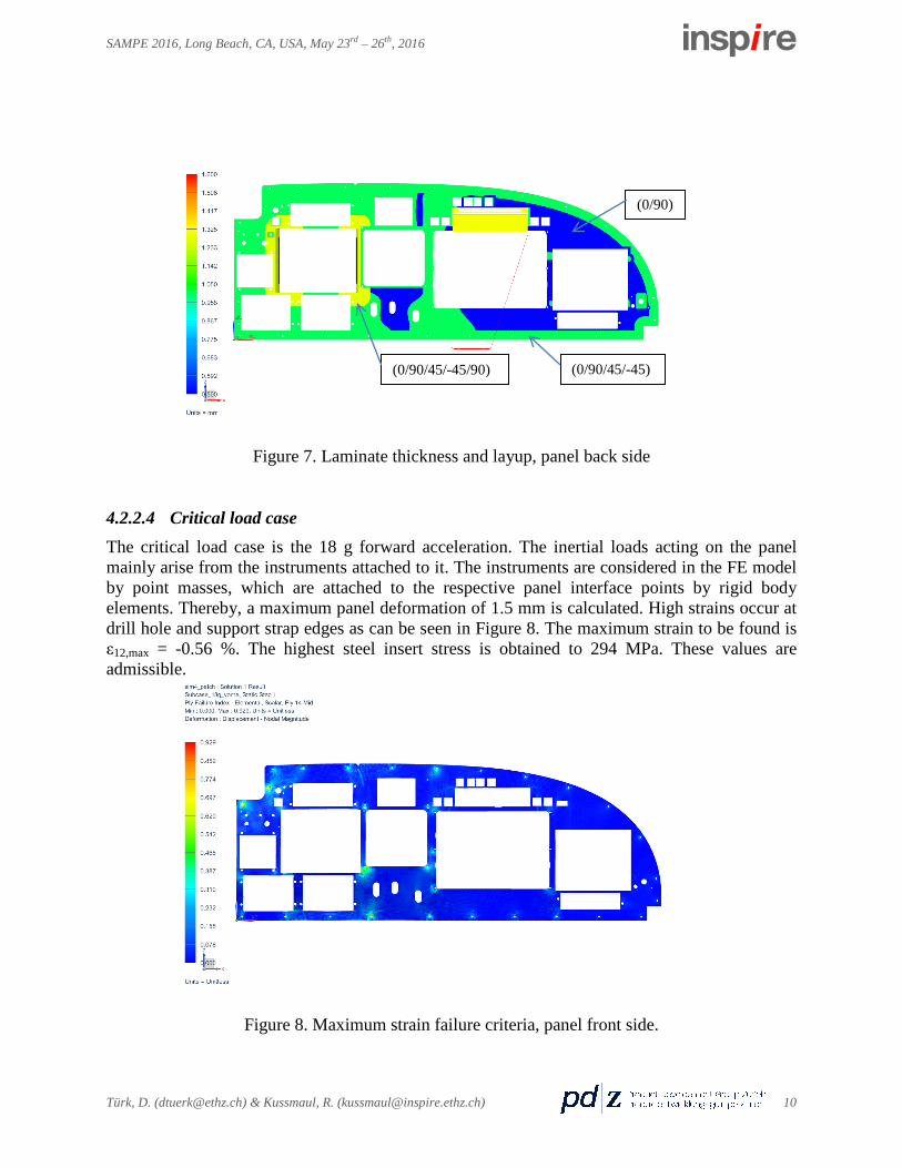
4.2.2.3 Layup The instrument panel face sheets are made from UD CFRP plies. The front side of the panel has a quasi-isotropic layup with a constant total thickness of 1 mm. On the backside of the panel a variable stiffness design with local reinforcements is pursued. The respective laminate layup is depicted in Figure 7. The 0° direction is along the X-axis.
Parameter Value Unit Strain fiber parallel 0.4 % Strain transverse 0.4 % Shear strain 0.6 %
upward
sideward forward
Türk, D. ([email protected]) & Kussmaul, R. ([email protected]) 9
SAMPE 2016, Long Beach, CA, USA, May 23rd – 26th, 2016
Figure 7. Laminate thickness and layup, panel back side
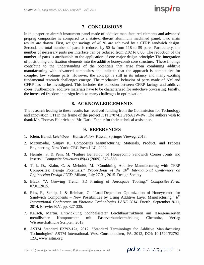
4.2.2.4 Critical load case The critical load case is the 18 g forward acceleration. The inertial loads acting on the panel mainly arise from the instruments attached to it. The instruments are considered in the FE model by point masses, which are attached to the respective panel interface points by rigid body elements. Thereby, a maximum panel deformation of 1.5 mm is calculated. High strains occur at drill hole and support strap edges as can be seen in Figure 8. The maximum strain to be found is ε12,max = -0.56 %. The highest steel insert stress is obtained to 294 MPa. These values are admissible.
Figure 8. Maximum strain failure criteria, panel front side.
(0/90/45/-45)
(0/90)
(0/90/45/-45/90)
Türk, D. ([email protected]) & Kussmaul, R. ([email protected]) 10

SAMPE 2016, Long Beach, CA, USA, May 23rd – 26th, 2016
4.3 Manufacturing of the Instrument Panel Made of AM and CFRP The general manufacturing route is described in Section 2 and consists of an autoclave process. A simple, 4 mm thick CFRP tooling plate is used. Three milled aluminum blocks are pin-positioned and screwed to the tooling plate. These blocks are used as reference points for attachments that stick out of the sandwich plane. Prepreg plies are cut to near-netshape. Four plies are draped on the tooling plate. Then, eight prefabricated SLS honeycomb cores are assembled via puzzle joints (cf. Figure 9). SLM inserts are placed in the SLS cores and those sticking out of the sandwich are pinned to the aluminum blocks. Six Nomex honeycomb segments are cut and inserted in designated areas. Machined Teflon blocks are used as placeholders for bigger cutouts. Top facings are placed on the core without additional adhesive (co-curing). Vacuum bagging is applied and the part is cured at 100°C and 1.5 bar. The part is heated at a rate of 1°C/min, held at 100°C for 2 h and cooled down to room temperature at a rate of 1°C/min. Next, the part is demolded and the final contour is machined. The final part is depicted in Figure 10.
Figure 9. Panel made of AM and CFRP during manufacturing, without facings.
Figure 10. Final part.
Türk, D. ([email protected]) & Kussmaul, R. ([email protected]) 11

SAMPE 2016, Long Beach, CA, USA, May 23rd – 26th, 2016
5. RESULTS This section presents the findings of the case study. Weight and number of parts of the aircraft instrument panel made by additive manufacturing and CFRP are assessed and compared to the reference panel.
5.1 Weight Figure 11 compares the weight of the aluminum reference panel with the demonstrator panel manufactured in this research. The weight is subdivided in areal (sheet metal, sandwich) components and elements used for connections and attachments (inserts). It can be seen that most weight savings arise from the sandwich concept with CFRP. The structural weight of the sandwich amounts to 716 g, including the CFRP facings and both the additive and the Nomex honeycomb cores. This stands against a sheet metal weight of 1335 g, resulting in weight savings of 46.4 % or 619 g. This implies on the other hand, that the load introduction elements are heavier in the demonstrator panel as they amount for 164 g compared to 146 g in the reference panel. This is an increase of 11.2 % or 18 g. The results show total weight savings of 40.6 % or 601 g.
Figure 11. Weight comparison
5.2 Number of Parts Figure 12 compares the number of parts of the demonstrator panel to the aluminum reference panel. Results indicate that the number of parts is reduced by 50 % from 118 to 59 parts. The integral panel made with AM and CFRP is considered to be composed of the following parts: 8 additive honeycomb core elements, 7 conventional honeycombs, 2 CFRP facings and 42 inserts. The aluminum panel uses 115 parts to provide 49 attachment interfaces for instruments and 8 interfaces for the mounting of the two sheet metal support straps. Therefore 2.02 parts per interface (PPI) are necessary for the differentially designed instrument panel. The demonstrator panel manages 49 interface points with 42 additive inserts, which results in 0.86 parts per interface. This is around 2.3 times less parts per interface. Due to the integration of the support
Türk, D. ([email protected]) & Kussmaul, R. ([email protected]) 12

SAMPE 2016, Long Beach, CA, USA, May 23rd – 26th, 2016
straps eight interface points are saved. In the differential design two rivets are required to position and fix one rivet nut, compared to the combined approach where one insert is plugged into the additive core. Furthermore, additive manufacturing allows to cover several interface points with one insert, thereby pushing the PPI below one. This is how the number of joining elements is reduced from 115 to 42 which corresponds to a decrease of 63.5 % or 73 parts.
Figure 12. Comparison of the number of parts
6. DISCUSSION The obtained weight savings of roughly 40 % mainly arise from the sandwich design which correlates with typical values in literature [19]. However, the design is not optimized yet. Through optimization weight savings of around 20 % are expected. With this assumption, the CFRP facing weight could be reduced to 344 g, an optimized additive core would amount to 215 g and the SLM inserts would weigh 131 g. The highly integrated panel would therefore weigh 708 grams, which corresponds to savings of 773 g or 52 %. Figure 13 shows a solid SLM insert (left) and an optimized insert (right). The solid insert weighs 4.43 g whereas with additive design the weight was reduced to only 1.58 g. This is a reduction of 64.3 %, highlighting the potential of tailored design with additive manufacturing. Weight reductions by AM of 30 to 40 % compared to conventional machined design are confirmed in literature [20, 21].
Figure 13. Comparison of a solid SLM insert (left) with an insert designed for AM (right).
Potential weight savings of 64.3 %.
Türk, D. ([email protected]) & Kussmaul, R. ([email protected]) 13
SAMPE 2016, Long Beach, CA, USA, May 23rd – 26th, 2016
7. CONCLUSIONS In this paper an aircraft instrument panel made of additive manufactured elements and advanced prepreg composites is compared to a state-of-the-art aluminum machined panel. Two main results are drawn. First, weight savings of 40 % are achieved by a CFRP sandwich design. Second, the total number of parts is reduced by 50 % from 118 to 59 parts. Particularly, the number of necessary parts per interface can be reduced from 2.02 to 0.86. The reduction of the number of parts is attributable to the application of one major design principle: The integration of positioning and fixation elements into the additive honeycomb core structure. These findings contribute to the understanding of the potentials that arise from combining additive manufacturing with advanced composites and indicate that the approach is competitive for complex low volume parts. However, the concept is still in its infancy and many exciting fundamental research challenges emerge. The mechanical behavior of parts made of AM and CFRP has to be investigated. This includes the adhesion between CFRP facings and additive cores. Furthermore, additive materials have to be characterized for autoclave processing. Finally, the increased freedom in design leads to many challenges in optimization.
8. ACKNOWLEDGEMENTS The research leading to these results has received funding from the Commission for Technology and Innovation CTI in the frame of the project KTI 17874.1 PFSATW-IW. The authors wish to thank Mr. Thomas Heinrich and Mr. Dario Fenner for their technical assistance.
9. REFERENCES 1. Klein, Bernd. Leichtbau – Konstruktion. Kassel, Springer Vieweg, 2013.
2. Mazumadar, Sanjay K. Composites Manufacturing: Materials, Product, and Process Engineering. New York: CRC Press LLC, 2002.
3. Heimbs, S. & Pein, M. “Failure Behaviour of Honeycomb Sandwich Corner Joints and Inserts.” Composite Structures 89(4) (2009): 575–588.
4. Türk, D., Klahn, C. & Meboldt, M. “Combining Additive Manufacturing with CFRP Composites: Design Potentials.” Proceedings of the 20th International Conference on Engineering Design ICED. Milano, July 27-31, 2015. Design Society.
5. Black. “A Growing Trend : 3D Printing of Aerospace Tooling.” CompositesWorld. 07.01.2015.
6. Riss, F., Schilp, J. & Reinhart, G. “Load-Dependent Optimization of Honeycombs for Sandwich Components – New Possibilities by Using Additive Layer Manufacturing.” 8th International Conference on Photonic Technologies LANE 2014. Fuerth, September 8-11, 2014. Elsevier B.V. pp. 327-335.
7. Kausch, Martin. Entwicklung hochbelasteter Leichtbaustrukturen aus lasergenerierten metallischen Komponenten mit Faserverbundverstärkung. Chemnitz, Verlag Wissenschaftliche Scripten, 2013.
8. ASTM Standard F2792-12a, 2012, “Standard Terminology for Additive Manufacturing Technologies” ASTM International. West Conshohocken, PA, 2012, DOI: 10.1520/F2792-12A, www.astm.org.
Türk, D. ([email protected]) & Kussmaul, R. ([email protected]) 14
SAMPE 2016, Long Beach, CA, USA, May 23rd – 26th, 2016
9. Roland Berger. Additive Manufacturing: A Game Changer for the Manufacturing Industry. Munich, Roland Berger Strategy Consultants, November 2013.
10. Gibson, Ian. Additive Manufacturing Technologies: Rapid Prototyping to Direct Digital Manufacturing. New York: Springer Science+Business Media, LLC 2010.
11. Zimmer, D. & Adam, G. A. O. “Direct Manufacturing Design Rules.” 5th International Conference on Advanced Research in Virtual and Rapid Prototyping. Leiria, 28.09 – 01.10.2011. Ed. Paulo Jorge da Silva Bartolo. Innovative Developments in Virtual and Physical Prototyping. pp. 545-551.
12. Leutenecker, B., Klahn, C. & Meboldt, M. “Indicators and Design Strategies for Direct Part Production by Additive Manufacturing.” Proceedings of the 20th International Conference on Engineering Design ICED. Milano, July 27-31, 2015. Design Society.
13. Jones, Robert M. Mechanics of Composite Materials. Philadelphia: Taylor & Francis, 1999.
14. Mallick, P.K. Fiber-Reinforced Composites: Materials, Manufacturing and Design, Third Edition. Boca Raton: CRC Press, 2007.
15. Gutowski, Timothy G. Advanced Composites Manufacturing. Cambridge: John Wiley & Sons, Inc., 1997.
16. Bitzer, Tom. Honeycomb Technology: Materials, Design, Manufacturing, Applications and Testing. Dublin: Springer-Science+Business Media, B.V., 1997.
17. Sodhi, R. S. & Sonnenberg, M. “Use of Snap-Fit Fasteners in the Multi-Life-Cycle Design of Products.“ Proceedings of the 1999 IEEE International Symposium on Electronics and the Environment. Danvers. May 11-13, 1999. IEEE. pp. 160-165.
18. EASA CS-23, 2012, “Certification Specifications for Normal, Utility, Aerobatic, and Commuter Category Aeroplanes” European Aviation Safety Agency. http://easa.europa.eu/system/files/dfu/CS-23%20Amdt%203.pdf
19. Johnson, A. F. & Sims, G. D. “Mechanical Properties and Design of Sandwich Materials.” Composites 17(4) (1986): 321-328.
20. Spierings, A. B., Levy, G., Labhart & Wegener, K. “Production of Functional Parts Using SLM – Opportunities and Limitations.” 5th International Conference on Advanced Research in Virtual and Rapid Prototyping. Leiria, 28.09 – 01.10.2011. Ed. Paulo Jorge da Silva Bartolo. Innovative Developments in Virtual and Physical Prototyping. pp. 785-790.
21. Emmelmann, C., Sander, P., Kranz, J. & Wycisk, E. „Laser Additive Manufacturing and Bionics: Redefining Lightweight Design:“ Physics Procedia 12 (2011): 364-368.
Türk, D. ([email protected]) & Kussmaul, R. ([email protected]) 15