Additional Channels for SC Instrumentation - Honeywell€¦ · Additional Channels for SC Series...
62
Pressure Transducers Load & Torque Cells Accelerometers Displacement Transducers Instrumentation Additional Channels for SC Instrumentation Temperature (RTD) Input, Frequency Input
Transcript of Additional Channels for SC Instrumentation - Honeywell€¦ · Additional Channels for SC Series...

PressureTransducers
Load & TorqueCells
Accelerometers
DisplacementTransducers
Instrumentation
Additional Channels forSC Instrumentation
Temperature (RTD) Input,Frequency Input

Sensotec, Inc.2080 Arlingate LaneColumbus, Ohio 43228 USACopyright © 2002 by Sensotec, Inc. all rights reservedTelephone: (614)850-5000FAX: (614)850-1111Toll Free: 1-800-848-6564E-mail: [email protected]: http://www.sensotec.com
Additional Channels for SC Series Instrumentation
Sensotec Document Number: 008-0608-01Rev. -: March, 2002
IMPORTANT It is recommended that you read the “SC Series Instruction Manual”, Sen-sotec document 008-0608-00 before using the channels described herein.
CAUTION: The operator of this instrument is advised that if the equipmentis not used in a manner not specified in this manual, the protection pro-vided by the equipment may be impaired.
CAUTION: Only qualified, service-trained personnel who are aware of thehazards involved should remove the cover from the instrument or connectexternal wiring to the instrument.
Sensotec and the Sensotec logo are registered trademarks of Sensotec,Inc.
Printed in U.S.A.
Sensotec continually improves its products, and thus the information hereinis subject to change without notice.

C
ON
TE
NT
S
Contents
Contents . . . . . . . . . . . . . . . . . . . . . . . . . . . . . . . . . . 3
Chapter 1 Introduction . . . . . . . . . . . . . . . . . . . . . . . . . . . . . . . . 5
1.1 About This Manual . . . . . . . . . . . . . . . . . . . . . . . 51.1.1 Scope . . . . . . . . . . . . . . . . . . . . . . . . . . . . . . . . . . . . . . 51.1.2 Conventions . . . . . . . . . . . . . . . . . . . . . . . . . . . . . . . . . 51.1.3 Organization . . . . . . . . . . . . . . . . . . . . . . . . . . . . . . . . 5
1.2 Related Documents . . . . . . . . . . . . . . . . . . . . . . 6
Chapter 2 RTD Input Channel . . . . . . . . . . . . . . . . . . . . . . . . . . 9
2.1 Features . . . . . . . . . . . . . . . . . . . . . . . . . . . . . . . 92.2 Getting Started Quickly . . . . . . . . . . . . . . . . . . . . 92.3 Wiring . . . . . . . . . . . . . . . . . . . . . . . . . . . . . . . . . 10
2.3.1 Channel Connector . . . . . . . . . . . . . . . . . . . . . . . . . . . 102.3.2 4-Wire RTD Connection . . . . . . . . . . . . . . . . . . . . . . . . 102.3.3 3-Wire RTD Connection . . . . . . . . . . . . . . . . . . . . . . . . 112.3.4 2-Wire RTD Connection . . . . . . . . . . . . . . . . . . . . . . . . 11
2.4 Calibration . . . . . . . . . . . . . . . . . . . . . . . . . . . . . . 122.5 Channel Specifications . . . . . . . . . . . . . . . . . . . . 132.6 Channel Menu . . . . . . . . . . . . . . . . . . . . . . . . . . . 14
2.6.1 OPEROPEROPEROPERAAAATIONTIONTIONTION Sub-Menu . . . . . . . . . . . . . . . . . . . . . . . . . 142.6.2 DISPDISPDISPDISPLLLLAY UNITSAY UNITSAY UNITSAY UNITS Menu Item . . . . . . . . . . . . . . . . . . . . . 152.6.3 AUXnAUXnAUXnAUXn FUNCTIONFUNCTIONFUNCTIONFUNCTION Menu Items . . . . . . . . . . . . . . . . . . . . 152.6.4 CALICALICALICALIBBBBRATION TRATION TRATION TRATION TYYYYPEPEPEPE Menu Item . . . . . . . . . . . . . . . . . . . 162.6.5 CALICALICALICALIBBBBRATION DRATION DRATION DRATION DAAAATATATATA Sub-Menu . . . . . . . . . . . . . . . . . . . 172.6.6 CALICALICALICALIBBBBRATERATERATERATE Menu Item . . . . . . . . . . . . . . . . . . . . . . . . . 172.6.7 DACDACDACDAC SSSSETUPETUPETUPETUP Sub-Menu . . . . . . . . . . . . . . . . . . . . . . . . . 192.6.8 DIAGDIAGDIAGDIAGNNNNOSTICSOSTICSOSTICSOSTICS Sub-Menu . . . . . . . . . . . . . . . . . . . . . . . 20
2.7 Analog Output Configuration . . . . . . . . . . . . . . . . 212.7.1 Identifying the Output Type . . . . . . . . . . . . . . . . . . . . . 212.7.2 Channel Menu Items . . . . . . . . . . . . . . . . . . . . . . . . . . 212.7.3 Output Selection . . . . . . . . . . . . . . . . . . . . . . . . . . . . . 21
2.8 Troubleshooting . . . . . . . . . . . . . . . . . . . . . . . . . 222.8.1 Error Messages . . . . . . . . . . . . . . . . . . . . . . . . . . . . . . 222.8.2 Common Problems and Solutions . . . . . . . . . . . . . . . . 22
2.9 Communication Commands . . . . . . . . . . . . . . . . 232.9.1 Introduction . . . . . . . . . . . . . . . . . . . . . . . . . . . . . . . . . 232.9.2 Descriptions . . . . . . . . . . . . . . . . . . . . . . . . . . . . . . . . . 23
Chapter 3 Frequency Input Channel . . . . . . . . . . . . . . . . . . . . . 33
3.1 Features . . . . . . . . . . . . . . . . . . . . . . . . . . . . . . . 333.2 Getting Started Quickly . . . . . . . . . . . . . . . . . . . . 333.3 Wiring . . . . . . . . . . . . . . . . . . . . . . . . . . . . . . . . . 34
3.3.1 Channel Connector . . . . . . . . . . . . . . . . . . . . . . . . . . . 34
Additional Channels for SC Series Instrumentation page 3

3.3.2 NPN Open-Collector Connection . . . . . . . . . . . . . . . . . 343.3.3 PNP Open-Collector . . . . . . . . . . . . . . . . . . . . . . . . . . . 353.3.4 TTL/CMOS Logic Connection . . . . . . . . . . . . . . . . . . . 353.3.5 Magnetic Pickup Connection . . . . . . . . . . . . . . . . . . . . 35
3.4 Calibration . . . . . . . . . . . . . . . . . . . . . . . . . . . . . 363.5 Channel Specifications . . . . . . . . . . . . . . . . . . . . 373.6 Channel Menu . . . . . . . . . . . . . . . . . . . . . . . . . . 38
3.6.1 OPEROPEROPEROPERAAAATIONTIONTIONTION Sub-Menu . . . . . . . . . . . . . . . . . . . . . . . . . . 383.6.2 AUXnAUXnAUXnAUXn FUNCTIONFUNCTIONFUNCTIONFUNCTION Menu Items . . . . . . . . . . . . . . . . . . . . . 383.6.3 CALICALICALICALIBBBBRATION TRATION TRATION TRATION TYYYYPEPEPEPE Menu Item . . . . . . . . . . . . . . . . . . . 393.6.4 CALICALICALICALIBBBBRATION DRATION DRATION DRATION DAAAATATATATA Sub-Menu . . . . . . . . . . . . . . . . . . . 403.6.5 CALICALICALICALIBBBBRATERATERATERATE Menu Item . . . . . . . . . . . . . . . . . . . . . . . . . 403.6.6 DACDACDACDAC SSSSETUPETUPETUPETUP Sub-Menu . . . . . . . . . . . . . . . . . . . . . . . . . . 413.6.7 DIAGDIAGDIAGDIAGNNNNOSTICSOSTICSOSTICSOSTICS Sub-Menu . . . . . . . . . . . . . . . . . . . . . . . . 42
3.7 Analog Output Configuration . . . . . . . . . . . . . . . 433.7.1 Identifying the Output Type . . . . . . . . . . . . . . . . . . . . . 433.7.2 Channel Menu Items . . . . . . . . . . . . . . . . . . . . . . . . . . 433.7.3 Output Selection . . . . . . . . . . . . . . . . . . . . . . . . . . . . . . 43
3.8 Troubleshooting . . . . . . . . . . . . . . . . . . . . . . . . . 443.8.1 Error Messages . . . . . . . . . . . . . . . . . . . . . . . . . . . . . . 443.8.2 Common Problems and Solutions . . . . . . . . . . . . . . . . 44
3.9 Communication Commands . . . . . . . . . . . . . . . . 453.9.1 Introduction . . . . . . . . . . . . . . . . . . . . . . . . . . . . . . . . . 453.9.2 Descriptions . . . . . . . . . . . . . . . . . . . . . . . . . . . . . . . . . 45
Chapter 4 Setup Menu Reference . . . . . . . . . . . . . . . . . . . . . . . 55
4.1 Navigation instructions . . . . . . . . . . . . . . . . . . . . 55
Index . . . . . . . . . . . . . . . . . . . . . . . . . . . . . . . . . . . . . 59
Warranty/Repair Policy . . . . . . . . . . . . . . . . . . . . . . 61
page 4 008-0608-01

IN
TR
OD
UC
TIO
N1
Chapter 1Introduction
1.1 About This Manual
1.1.1 Scope This manual will explain the setup, features and operation of additional Input andOutput channels that may be installed into Sensotec’s 3rd generation SC SEriesinstruments. This series includes the models SC1000, SC2000, SC2001 andSC3004.
1.1.2 Conventions This manual uses the following conventions to present information:
1.1.3 Organization Chapter 1, “Introduction”, offers general information about this instruction man-ual.
Chapter 2, “RTD Input Channel”, explains how to wire, configure, operate andcalibrate the RTD Input channel.
Chapter 3, “Frequency Input Channel”, explains how to wire, configure, oper-ate and calibrate the Frequency Input channel.
Chapter 4, “Setup Menu Reference”, is a list of all SETUP menus and a cross-reference to related information in this instruction manual.
[TEXT IN BRACKETS] The label of a front panel button.
DDDDIIIISSSSPPPPLLLLAAAAYYYY Text that appears on the display, such as error messages or menu items.
-> Indicates that what follows is an item from a sub-menu, such as SSSSYYYYSSSSTTTTEEEEMMMM MENMENMENMENUUUU -> DDDDIIIIAAAAGGGGNNNNOOOOSSSSTTTTIIIICCCCSSSS.
DATA Serial communications commands sent to (or replies from) the instrument
↵ The carriage-return character, ASCII code decimal 13
Note
Notes contain important information set off from the text.
A stop sign highlights procedures or information necessary to avoid damage to equipment, dam-age to software, loss of data, loss of calibration, or invalid test results.
The caution symbol alerts that a specific proce-dure or practice which, is not followed correctly, could cause serious personal injury.
Additional Channels for SC Series Instrumentation page 5

1.2 Related Documents
SC Series InstructionManual
The “SC Series Instruction Manual”, Sensotec p/n 008-0608-00, describes the wiring,setup and operation of the chassis and channels of SC Series Instruments. The chan-nels described in this document are:
• Strain-Gage Input channel• AC/AC-LVDT Input channel• High-Level Input channel• Relay Output channel• DAC Output channel• Split-Display Virtual channel• Mathematics Virtual channel
A printed copy of this document is available for order, or you may download it for freeSensotec’s web site, www.sensotec.com.
Customer InformationSheet
Every instrument is shipped with a Customer Information Sheet which documents theconfiguration of the instrument when it left the factory. Such information includes:
• Sensotec part number,• date of manufacture,• list of all installed channels and their setup information,• customer specific SensoCode programming of Mathematics Virtual channels and
operation notes.
CommunicationsGuide
The “SC Series Communications Guide”, Sensotec p/n 008-0610-00, describes indetail how to communicate with an SC Series instrument using RS-232 and RS-485.Wiring diagrams, sample programs, and command descriptions are included.
A printed copy of this document is available for order, or you may download it for freeSensotec’s web site, www.sensotec.com.
page 6 008-0608-01

IN
TR
OD
UC
TIO
N1
Additional Channels for SC Series Instrumentation page 7

page 8 008-0608-01

R
TD
INP
UT
CH
AN
NE
L2
Chapter 2RTD Input Channel
2.1 Features
The RTD Input channel provides a DC excitation current to and accepts millivoltsignals from a standard platinum, 100Ω Resistance Temperature Detector (RTD).These signals are digitized, converted into engineering units, and placed into thetrack, peak and valley data values of the channel.
Setup and calibration of the channel is made at the factory for operation with acustomer-supplied Pt-100 RTD with a DIN-43760 standard calibration curve. Re-calibration can be made manually through the SETUP mode with the known-loadcalibration method and a customer-supplied RTD calibrator.
The engineering units used to display the temperature readings are field select-able from a built-in conversion table. In addition, the engineering units used forcalibration can be independently selected.
Two rear panel control inputs can be field-configured for such functions as remotetrack/hold, disabling peak/valley detection and clearing the peak/valley values. Avoltage or current digital-to-analog output is also provided.
2.2 Getting Started Quickly
As shipped from the factory, the RTD Input channel is calibrated for a standardPt100 (platinum, 100Ω @ 100ºC) RTD that conforms to the DIN-43760 / IEC751standards (∝=0.00385). No further calibration is required prior to use.
Connect the RTD to the RTD Input channel according to “Wiring” on page 10.
Additional Channels for SC Series Instrumentation page 9

2.3 Wiring
2.3.1 ChannelConnector
The pin-out for the channel’s connector is shown in the following table.
The Analog Output and Analog Return pins are electrically isolated from all other pinson the instrument.
Do not connect anything to the pins labeled as “N/C”. Damage to the instru-ment or loss of accuracy may result.
2.3.2 4-Wire RTDConnection
Use a 4-wire RTD connection when the highest possible accuracy is desired. Theexcitation current from the instrument will be carried by two wires and the voltage dropacross the RTD will be sensed with the other two wires. Since the (+)Signal and (-)Signal pins are high impedance inputs, there is little current flow through these wirestherefore the resistance of the wires doesn’t add to the resistance of the RTD.
Figure 2-1: “4-wire RTD Connection” to RTD Input Channel
Table 2-1: RTD Input Channel Pin Connections
Pin Label Function NOTES
1 (top) +EXC (+)Excitation referenced to pin 10
2 N/C N/C DO NOT CONNECT!
3 N/C N/C DO NOT CONNECT!
4 -EXC (-)Excitation referenced to pin 10
5 +SIG (+)Signal referenced to pin 10
6 -SIG (-)Signal referenced to pin 10
7 +OUT Analog Output referenced to pin 8
8 -OUT Analog Return -
9 N/C N/C DO NOT CONNECT!
10 DGND Digital Ground -
11 AUX1 Auxiliary Function 1 (connect to pin 10 to activate)
referenced to pin 10
12(bottom)
AUX2 Auxiliary Function 2 (connect to pin 10 to activate)
referenced to pin 10
page 10 008-0608-01

R
TD
INP
UT
CH
AN
NE
L2
2.3.3 3-Wire RTDConnection
If the cost of 4-wire cable is an issue, it is possible to use a 3-wire RTD connec-tion that shares many of the benefits of the 4-wire connection. The wire lengthsshould be equal and the wire type should be identical. This will equalize wireresistance and thus obtain the best accuracy.
Figure 2-2: “3-Wire RTD” Connection to RTD Input Channel
2.3.4 2-Wire RTDConnection
The 2-wire connection scheme is not recommended unless the cable length isshort. The wire’s resistance will add to the resistance of the RTD and result inreduced accuracy.
Figure 2-3: “2-Wire RTD Connection” to RTD Input Channel
Additional Channels for SC Series Instrumentation page 11

2.4 Calibration
A listing of all menu items for this channel is given in “Setup Menu Reference” onpage 55.
A customer-supplied RTD simulator/calibrator is required for re-calibration.
Although not recommended, field re-calibration of the channel for operation with RTDs with outputs other than the Pt100 DIN-43760 / IEC751 standards
can be made; this may result in reduced accuracy and resolution.
Step 1: Wire the RTD simulator/calibrator to the channel’s connector.See “Wiring” on page 10.
Step 2: Enter the CCCCAAAALLLLIBIBIBIBRRRRAAAATTTTIIIIOOOONNNN DATDATDATDATAAAA. See “CALIBRATION DATA Sub-Menu” on page17.
If you wish to re-calibrate the instrument using a unit-of-measure other thandegrees Celsius, you can use the CCCCALALALALIIIIBBBBRRRRAAAATTTTIIIIOOOON UN UN UN UNNNNIIIITTTTSSSS menu item to change theunits-of-measure that the instrument uses for calibration.
Step 3: Perform the calibration.See “CALIBRATE Menu Item” on page 17.
Using the CCCCAAAALLLLIIIIBBBBRRRRAAAATTTTEEEE menu item starts the calibration process. You will beprompted to use your RTD simulator/calibrator to apply simulated RTD signalsto the channel as required.
page 12 008-0608-01

R
TD
INP
UT
CH
AN
NE
L2
2.5 Channel Specifications
RTD INPUT
Excitation Current 0.25mA
Factory Calibration For use with Pt100 RTD that use DIN-43760 / IEC751 standard (∝=0.00385)
Absolute Accuracy of Factory Calibra-tion
±0.5ºC max. from -200ºC to +200ºC
Resolution ±0.2ºC
A/D Converter 24-bit Sigma-Delta
Low-pass filter digital, 24-tap FIR
Frequency Response 16 Hz
Step Response 55 ms (typical)
Maximum Input Resistance ~250Ω
AUXILLIARY INPUTS
Quantity 2
Type momentary contact closure
Response Time < 5ms
Field-Selectable Functions peak/valley clear, peak/valley hold,track hold
ANALOG OUTPUT
Output voltage range 5, ±5, 10 or ±10 VDC (field selectable)
Output current range (optional currentoutput channels)
4-20 mA
Source any channel’s track, peak or valley value
Isolation 500V
Resolution 13 bits
Frequency Response same as input when driven by the same channel’s tracking data
Additional Channels for SC Series Instrumentation page 13

2.6 Channel Menu
The RTD Input channel is configured and calibrated via its channel menu. Detailedinstructions on operating the instrument in the SETUP Menu mode can be found inthe “SC Series Instruction Manual”, Sensotec p/n 008-0608-00.
2.6.1 OPOPOPOPEEEERATIONRATIONRATIONRATION
Sub-MenuThis menu controls the operation of this channel when the instrument is in the RUNmode.
PPPPOOOOWWWWEEEERRRR----OOOONNNN SOURCSOURCSOURCSOURCEEEE MenuItem
This menu selects which value is displayed by the channel when first entering theRUN mode.
The choices are:
• “TTTTRRRRAAAACCCCKKKK” means the live tracking value of the channel. • “PPPPEEEEAAAAKKKK” means the highest value of the channel.• “VVVVAAAALLLLLLLLEEEEYYYY” means the lowest value of the channel.
page 14 008-0608-01
R
TD
INP
UT
CH
AN
NE
L2
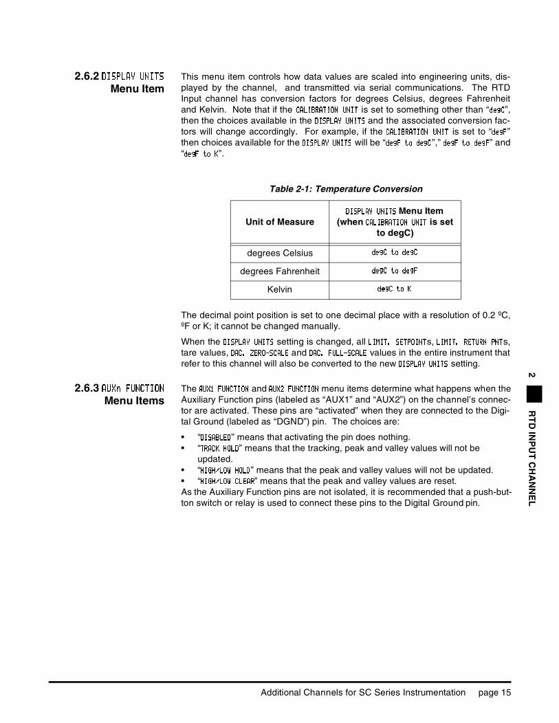
2.6.2 DISPLADISPLADISPLADISPLAYYYY UNITSUNITSUNITSUNITS
Menu ItemThis menu item controls how data values are scaled into engineering units, dis-played by the channel, and transmitted via serial communications. The RTDInput channel has conversion factors for degrees Celsius, degrees Fahrenheitand Kelvin. Note that if the CCCCAAAALLLLIIIIBBBBRRRRAAAATTTTIIIIOOOON UN UN UN UNNNNIIIITTTT is set to something other than “ddddeeeeggggCCCC”,then the choices available in the DDDDIIIISSSSPPPPLLLLAAAAY UNIY UNIY UNIY UNITTTTSSSS and the associated conversion fac-tors will change accordingly. For example, if the CCCCAAAALLLLIIIIBBBBRRRRAAAATTTTIIIIOOOON UN UN UN UNNNNIIIITTTT is set to “ddddeeeeggggFFFF”then choices available for the DDDDIIIISSSSPPPPLALALALAYYYY UNITUNITUNITUNITSSSS will be “ddddeeeeggggFFFF to degto degto degto degCCCC”,” ddddeeeeggggFFFF to degto degto degto degFFFF” and“ddddeeeeggggFFFF tttto Ko Ko Ko K”.
The decimal point position is set to one decimal place with a resolution of 0.2 ºC,ºF or K; it cannot be changed manually.
When the DDDDIIIISSSSPPPPLLLLAAAAYYYY UUUUNNNNIIIITTTTSSSS setting is changed, all LLLLIIIIMMMMIIIITTTT.... SSSSEEEETTTTPPPPOOOOIIIINNNNTTTTs, LLLLIIIIMMMMITITITIT. R. R. R. REEEETTTTUUUURRRRNNNN PPPPNNNNTTTTs,tare values, DDDDAAAACCCC. Z. Z. Z. ZEEEERRRROOOO----SSSSCCCCAAAALLLLEEEE and DDDDACACACAC.... FFFFUUUULLLLLLLL----SSSSCACACACALLLLEEEE values in the entire instrument thatrefer to this channel will also be converted to the new DIDIDIDISSSSPPPPLLLLAAAAYYYY UNITUNITUNITUNITSSSS setting.
2.6.3 AUXn FAUXn FAUXn FAUXn FUUUUNCTIONNCTIONNCTIONNCTION
Menu ItemsThe AAAAUUUUXXXX1 FU1 FU1 FU1 FUNNNNCCCCTTTTIIIIOOOONNNN and AAAAUUUUXXXX2222 FFFFUUUUNNNNCCCCTTTTIIIIOOOONNNN menu items determine what happens when theAuxiliary Function pins (labeled as “AUX1” and “AUX2”) on the channel’s connec-tor are activated. These pins are “activated” when they are connected to the Digi-tal Ground (labeled as “DGND”) pin. The choices are:
• “DDDDIIIISSSSAAAABBBBLLLLEEEEDDDD” means that activating the pin does nothing.• “TTTTRRRRAAAACCCCKKKK HOLHOLHOLHOLDDDD” means that the tracking, peak and valley values will not be
updated.• “HHHHIIIIGGGGHHHH////LLLLOOOOWWWW HOLHOLHOLHOLDDDD” means that the peak and valley values will not be updated.• “HHHHIIIIGGGGHHHH////LLLLOOOOWWWW CLEACLEACLEACLEARRRR” means that the peak and valley values are reset.As the Auxiliary Function pins are not isolated, it is recommended that a push-but-ton switch or relay is used to connect these pins to the Digital Ground pin.
Table 2-1: Temperature Conversion
Unit of MeasureDDDDIIIISSSSPPPPLLLLAAAAYYYY UNITUNITUNITUNITSSSS Menu Item
(when CCCCAAAALLLLIIIIBBBBRRRRAAAATTTTIIIIOOOONNNN UNIUNIUNIUNITTTT is set to degC)
degrees Celsius ddddeeeeggggCCCC to dto dto dto deeeeggggCCCC
degrees Fahrenheit ddddeeeeggggCCCC to dto dto dto deeeeggggFFFF
Kelvin ddddeeeeggggCCCC totototo KKKK
Additional Channels for SC Series Instrumentation page 15

2.6.4 CALICALICALICALIBBBBRATIONRATIONRATIONRATION
TYPETYPETYPETYPE Menu ItemThe only choice is:
• “TTTTYYYYPPPPEEEE==== 5 P5 P5 P5 POOOOIIIINNNNT CAT CAT CAT CALLLL ” means 5-Point Known Load Calibration. You are prompted to use your RTD simulator/calibrator to simulate the RTD output at the temperatures entered in the “KKKKNNNNOWOWOWOWN PN PN PN POOOOIIIINNNNTTTT 1111////5555”, “KKKKNNNNOOOOWWWWNNNN PPPPOOOOIIIINNNNT 2T 2T 2T 2////5555”, “KKKKNNNNOOOOWWWWNNNN PPPPOOOOIIIINNNNTTTT 3333////5555”, “KKKKNNNNOOOOWWWWN PN PN PN POIOIOIOINNNNT 4T 4T 4T 4////5555” and “KKKKNNNNOOOOWWWWNNNN POINT 5/POINT 5/POINT 5/POINT 5/5555 ” registers. This technique is used to compensate for the non-linearity inherent in RTDs.
The calibration points used for factory calibration are -200ºC, -100ºC, +0ºC, +100ºCand +200ºC. Using these temperatures for calibration is recommended for most appli-cations. If desired, accuracy may be improved by calibrating over a narrower temper-ature range which decreases the difference between the points.
Choosing calibration points where the difference between points is larger than 100ºC will result in greatly reduced accuracy.
page 16 008-0608-01

R
TD
INP
UT
CH
AN
NE
L2
2.6.5 CALIBRATICALIBRATICALIBRATICALIBRATIOOOON DATAN DATAN DATAN DATA
Sub-Menu
CCCCALALALALIIIIBBBBRRRRAAAATTTTIIIIOOOONNNN UNIUNIUNIUNITTTT Menu Item This menu item controls what units of measure are used for the known-load cali-bration points.
KKKKNNNNOOOOWWWWNNNN POINT x/POINT x/POINT x/POINT x/yyyy Menu Items This enters the engineering unit values for the known-load calibration points.These points must match the actual temperatures that you will apply to the instru-ment during calibration. The following menu items are available:
• “KKKKNNNNOOOOWWWWNNNN POINT 1/POINT 1/POINT 1/POINT 1/5555 ”: point 1 of 5, usually -200ºC.• “KKKKNNNNOOOOWWWWNNNN POINT 2/POINT 2/POINT 2/POINT 2/5555 ”: point 2 of 5, usually -100ºC.• “KKKKNNNNOOOOWWWWNNNN POINT 3/POINT 3/POINT 3/POINT 3/5555 ”: point 3 of 5, usually 0 ºC.• “KKKKNNNNOOOOWWWWNNNN POINT 4/POINT 4/POINT 4/POINT 4/5555 ”: point 4 of 5, usually +100ºC.• “KKKKNNNNOOOOWWWWNNNN POINT 5/POINT 5/POINT 5/POINT 5/5555 ”: point 5 of 5, usually +200ºC.
The instrument expects the input signal applied at each known-load point to be increasing. For example, the load applied at Known-Load Point 2/5
must cause the transducer to produce a more positive output than at Known-Load Point 1/5.
2.6.6 CALIBRATCALIBRATCALIBRATCALIBRATEEEE MenuItem
This menu item performs a calibration according to what was entered in the CCCCAAAALLLLIIII----BBBBRRRRAAAATTTTIIIIOOOONNNN TYPTYPTYPTYPEEEE and CCCCAAAALLLLIIIIBBBBRRRRAAAATTTTIIIIOOOONNNN DATDATDATDATAAAA menu items.
Before performing a calibration, the CCCCAAAALLLLIIIIBBBBRRRRAAAATTTTIIIIOOOON DN DN DN DAAAATTTTAAAA must be entered (see “CALIBRATION DATA Sub-Menu” on page 17).
For maximum accuracy, allow at least five minutes of warm-up before cal-ibration.
The CCCCAAAALLLLIIIIBBBBRRRRAAAATTTTIIIIOOOONNNN TYPTYPTYPTYPEEEE is 5-Point Known Load Calibration.
• The display will read DDDDOOOOIIIINNNNGGGG 5555PPPPOIOIOIOINNNNTTTT CCCCAAAALLLL, and prompt you to AAAAPPPPPPPPLLLLYYYY ----222200000000....00000000 degdegdegdegCCCC (or whatever the settings of KNOWN PKNOWN PKNOWN PKNOWN POOOOIIIINNNNT 1/T 1/T 1/T 1/5555 and CCCCAAAALLLLIIIIBBBBRRRRAAAATTTTIIIIOOOONNNN UNIUNIUNIUNITTTT are). When you have applied this simulated temperature, press [ENTER].
• The display will read WWWWOOOORRRRKKKKIIIINNNNGGGG, then AAAAPPPPPPPPLLLLYYYY -100.00 d-100.00 d-100.00 d-100.00 degegegegCCCC (or whatever the settings of KKKKNNNNOOOOWWWWNNNN POINT 2POINT 2POINT 2POINT 2////5555 and CACACACALLLLIIIIBBBBRRRRAAAATTTTIIIIOOOONNNN UNIUNIUNIUNITTTT are). When you have applied this simu-
Table 2-2: Temperature Conversion
Unit of Measure CCCCAAAALLLLIBIBIBIBRRRRAAAATTTTIIIIOOOONNNN UNIUNIUNIUNITTTT Menu Item
degrees Celsius ddddeeeeggggCCCC
degrees Fahrenheit ddddeeeeggggFFFF
Kelvin KKKK
Additional Channels for SC Series Instrumentation page 17
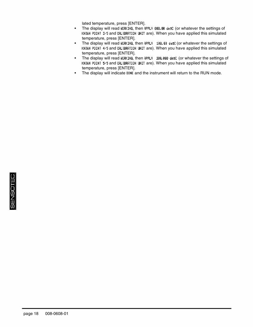
lated temperature, press [ENTER].• The display will read WWWWOOOORRRRKKKKIIIINNNNGGGG, then AAAAPPPPPPPPLLLLYYYY 000.00 d000.00 d000.00 d000.00 deeeeggggCCCC (or whatever the settings of
KKKKNNNNOOOOWWWWNNNN POINT 3POINT 3POINT 3POINT 3/5/5/5/5 and CCCCAAAALLLLIIIIBBBBRRRRAAAATTTTIIIIOOOONNNN UNIUNIUNIUNITTTT are). When you have applied this simulated temperature, press [ENTER].
• The display will read WWWWOOOORRRRKKKKIIIINNNNGGGG, then AAAAPPPPPPPPLLLLYYYY 100.00 d100.00 d100.00 d100.00 degegegegCCCC (or whatever the settings of KKKKNNNNOOOOWWWWNNNN POINT 4POINT 4POINT 4POINT 4/5/5/5/5 and CCCCAAAALLLLIIIIBBBBRRRRAAAATTTTIIIIOOOONNNN UNIUNIUNIUNITTTT are). When you have applied this simulated temperature, press [ENTER].
• The display will read WWWWOOOORRRRKKKKIIIINNNNGGGG, then AAAAPPPPPPPPLLLLYYYY 200.000 d200.000 d200.000 d200.000 deeeeggggCCCC (or whatever the settings of KKKKNNNNOOOOWWWWNNNN POINT 5POINT 5POINT 5POINT 5/5/5/5/5 and CCCCAAAALLLLIIIIBBBBRRRRAAAATTTTIIIIOOOONNNN UNIUNIUNIUNITTTT are). When you have applied this simulated temperature, press [ENTER].
• The display will indicate DDDDOOOONNNNEEEE and the instrument will return to the RUN mode.
page 18 008-0608-01

R
TD
INP
UT
CH
AN
NE
L2
2.6.7 DADADADACCCC SETUPSETUPSETUPSETUP
Sub-MenuThis sub-menu contains four items that control the Digital-to-Analog Converter(DAC) output of the channel.
DDDDAAAACCCC.... CHANNECHANNECHANNECHANNELLLL Menu Item This chooses which channel will drive the DAC output. Normally, the DAC locatedon a particular channel will be driven by that channel, but that need not be thecase. For example, if a Mathematics Virtual channel is installed on the instru-ment, the output of this Virtual channel could be used to drive this channel’s DACoutput.
If the DAC is set-up to be driven by its own channel’s tracking value, the AnalogOutput will have the frequency response specified by “Channel Specifications” onpage 13. Otherwise, the Analog Output will operate more slowly.
DDDDAAAACCCC.... SOURCSOURCSOURCSOURCEEEE Menu Item This designates the data source of the channel monitored by the analog output.Each channel has three data sources: the live tracking value (TRACK), its highestvalue (PEAK), and its lowest value (VALLEY).
The options for this menu item are:
• “TTTTRRRRAAAACCCCKKKK” means the live tracking value of the channel. • “PPPPEEEEAAAAKKKK” means the highest value of the channel since the peak/valley detector
was last cleared.• “VVVVAAAALLLLLLLLEEEEYYYY” means the lowest value of the channel since the peak/valley detector
was last cleared.If the DAC is set-up to be driven by its own channel’s tracking value, the AnalogOutput will have the frequency response specified by “Channel Specifications” onpage 13. Otherwise, the Analog Output will operate more slowly.
DADADADACCCC.... ZERO-SCALZERO-SCALZERO-SCALZERO-SCALEEEE Menu Item This specifies what value, in engineering units, corresponds to zero output on theAnalog Output.
“Zero output” might be 0 Volts, 2.5 Volts, 5 Volts, 4 mA or 12 mA depending on ifthe channel has a voltage or current output and how it is configured. See the“Digital-to-Analog Output” section of this chapter for details.
DADADADACCCC.... FULL-SCALFULL-SCALFULL-SCALFULL-SCALEEEE Menu Item Specifies what value, in engineering units, corresponds to full output on the Ana-log Output.
“Full output” might be 5 Volts, 10 Volts or 20 mA depending on if the channel hasa voltage or current output and how it is configured. See the “Digital-to-AnalogOutput” section of this chapter for details.
Additional Channels for SC Series Instrumentation page 19

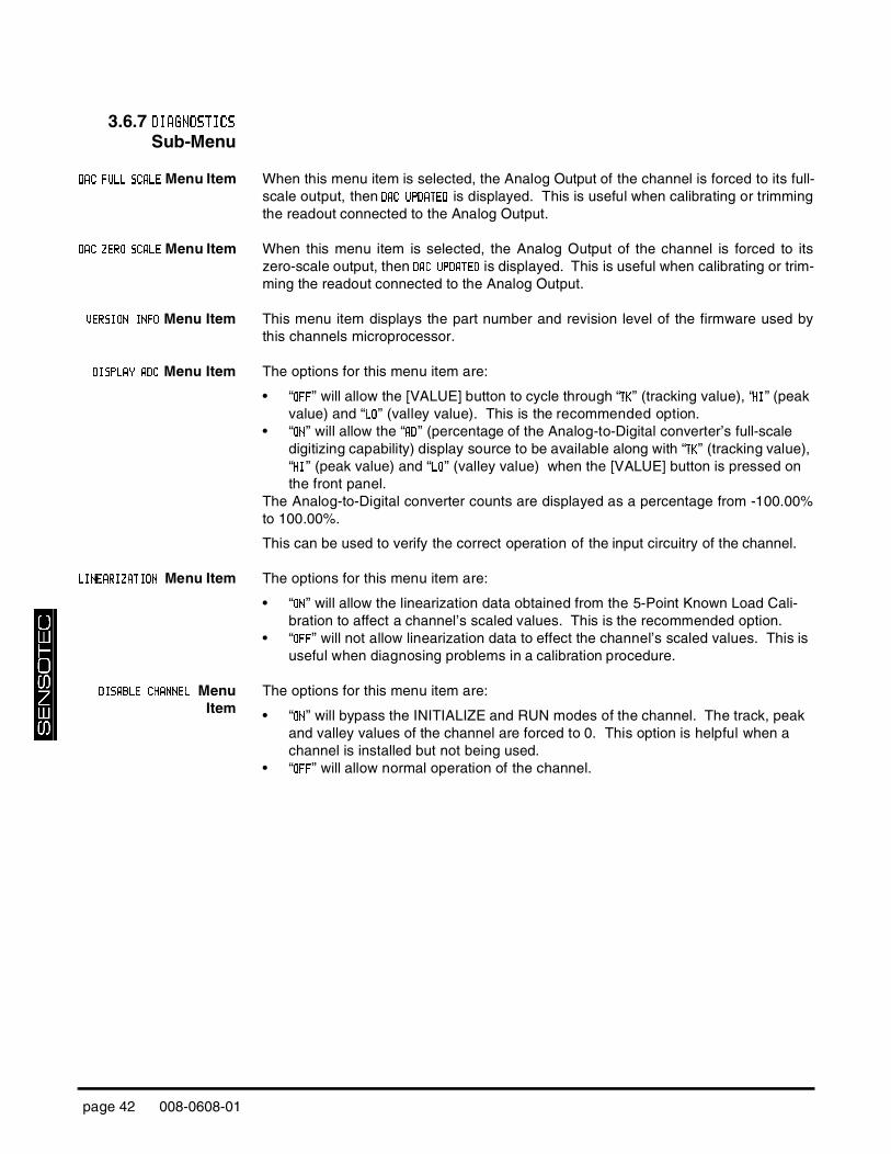
2.6.8 DIAGDIAGDIAGDIAGNNNNOSTICSOSTICSOSTICSOSTICS
Sub-Menu
DDDDAAAACCCC FFFFUUUULLLLL SL SL SL SCCCCAAAALLLLEEEE Menu Item When this menu item is selected, the Analog Output of the channel is forced to its full-scale output, then DDDDAAAACCCC UUUUPPPPDDDDAAAATTTTEEEEDDDD is displayed. This is useful when calibrating or trimmingthe readout connected to the Analog Output.
DDDDAAAACCCC ZZZZEEEERRRRO SO SO SO SCCCCAAAALLLLEEEE Menu Item When this menu item is selected, the Analog Output of the channel is forced to itszero-scale output, then DDDDAAAAC UPC UPC UPC UPDDDDAAAATTTTEEEEDDDD is displayed. This is useful when calibrating or trim-ming the readout connected to the Analog Output.
VVVVEEEERRRRSSSSIIIIOOOONNNN INFINFINFINFOOOO Menu Item This menu item displays the part number and revision level of the firmware used bythis channels microprocessor.
DDDDIIIISSSSPPPPLLLLAAAAYYYY ADADADADCCCC Menu Item The options for this menu item are:
• “OOOOFFFFFFFF” will allow the [VALUE] button to cycle through “TTTTKKKK” (tracking value), “HHHHIIII” (peak value) and “LLLLOOOO” (valley value). This is the recommended option.
• “OOOONNNN” will allow the “AAAADDDD” (percentage of the Analog-to-Digital converter’s full-scale digitizing capability) display source to be available along with “TTTTKKKK” (tracking value), “HHHHIIII” (peak value) and “LLLLOOOO” (valley value) when the [VALUE] button is pressed on the front panel.
The Analog-to-Digital converter counts are displayed as a percentage from -100.00%to 100.00%.
This can be used to verify the correct operation of the input circuitry of the channel.
LLLLIIIINNNNEEEEAAAARRRRIIIIZZZZAAAATTTTIIIIONONONON Menu Item The options for this menu item are:
• “OOOONNNN” will allow the linearization data obtained from the 5-Point Known Load Cali-bration to affect a channel’s scaled values. This is the recommended option.
• “OOOOFFFFFFFF” will not allow linearization data to effect the channel’s scaled values. This is useful when diagnosing problems in a calibration procedure.
DDDDIIIISSSSAAAABBBBLLLLEEEE CCCCHHHHAAAANNNNNNNNEEEELLLL MenuItem
The options for this menu item are:
• “OOOONNNN” will bypass the INITIALIZE and RUN modes of the channel. The track, peak and valley values of the channel are forced to 0. This option is helpful when a channel is installed but not being used.
• “OOOOFFFFFFFF” will allow normal operation of the channel.
page 20 008-0608-01

R
TD
INP
UT
CH
AN
NE
L2
2.7 Analog Output Configuration
2.7.1 Identifying theOutput Type
A RTD Input channel is available with one of two types of digital-to-analog (DAC)outputs: voltage or current. You can determine which type of output a channelhas by one of three ways:
• Consulting the instrument’s Customer Information Sheet• Examining the SSSSYYYYSSSSTTTTEEEEMMMM MENMENMENMENUUUU -> CCCCOOOONNNNFFFFIIIIGGGGUUUURRRRAAAATTTTIIIIOOOONNNN -> CCCCHHHHAAAANNNNNNNNEEEELLLL nn TTTTYYYYPPPPEEEE menu item where
nn is the number of the channel. If the channel’s type is RRRRTTTTDDDD VVVVoooouuuutttt, it has a volt-age output. If the channel’s type is RRRRTTTTDDDD IoIoIoIoutututut, it has a current output.
• Examining the channel’s circuit board as shown in the figure below.
2.7.2 Channel MenuItems
The Analog Output can be driven by any channel’s track, peak or valley value.
See the “Channel Menu” section earlier in this chapter for a complete listing ofSETUP menu items available on the DDDDAAAACCCC.... SETUSETUSETUSETUPPPP sub-menu.
2.7.3 Output Selection Jumpers located on the channel’s circuit board determine what outputs are gener-ated when the value selected to drive the Analog Output (from the DDDDAAAACCCC. CH. CH. CH. CHAAAANNNNNNNNEEEELLLL andDDDDAAAACCCC.... SOURCSOURCSOURCSOURCEEEE menu items) equals the DADADADACCCC.... FULL SFULL SFULL SFULL SCCCCALALALALEEEE and DDDDAAAACCCC.... ZERO SZERO SZERO SZERO SCCCCAAAALLLLEEEE settings.
Figure 2-4: Digital-to-Analog Output Jumper Locations
DDDDAAAACCCC.... ZZZZEEEERRRROOOO SCALSCALSCALSCALEEEE
OutputDDDDAAAACCCC.... FFFFUUUULLLLLLLL SCALSCALSCALSCALEEEE
OutputJ30
jumperJ31
jumper
CHANNELS WITH VOLTAGE OUPUT
0-5V 2.5 Volts 5 Volts open closed
±5V 0 Volts 5 Volts open open
0-10V 5 Volts 10 Volts closed closed
±10V 0 Volts 10 Volts closed open
CHANNELS WITH CURRENT OUTPUT
4-20mA 4 mA 20 mA open open
4-20mA 12 mA 20 mA open closed
Additional Channels for SC Series Instrumentation page 21

2.8 Troubleshooting
2.8.1 ErrorMessages
See the “Error Messages” chapter of the “SC Series Instruction Manual”, Sensotec p/n 008-0608-00, for information relating to error messages.
2.8.2 CommonProblems and
Solutions
Erratic Display Make sure that the temperature on the RTD is constant. A RTD simulator/calibratormay be used.
The RTD Input channel is calibrated at the factory for Pt100 RTD’s with the DIN stan-dard output curve. See “Channel Specifications” on pag e13.
It is recommended that the RTD Input channel be calibrated at -200ºC, -100ºC, 0ºC,+100ºC and +200ºC for rated accuracy.
+OVLD or -OVLD onDisplay
Check “Wiring” on page 10 and make certain that nothing is connected to the pinslabeled as “N/C”.
The RTD Input channel is calibrated at the factory for Pt100 RTD’s with the DIN stan-dard output curve. See “Channel Specifications” on pag e13.
Analog OutputIncorrect
Make certain of the type of Analog Output (voltage or current) that the channel isequipped with; see “Identifying the Output Type” on page21.
Use the DDDDIIIIAAAAGGGGNONONONOSSSSTTTTIIIICCCCSSSS -> DDDDACACACAC FFFFULULULULLLLL SCSCSCSCAAAALLLLEEEE and DDDDIIIIAAAAGGGGNNNNOOOOSSSSTTTTIIIICCCCSSSS -> DDDDAAAAC ZC ZC ZC ZEEEERRRRO SO SO SO SCCCCAAAALLLLEEEE menu items toforce the Analog Output to a known output. Then, adjust your readout device, panelmeter, PLC or data acquisition system to match.
Check the output selection jumpers; see “Output Selection” on page 21.
Auxiliary FunctionPins Not Operating
Make sure that the AAAAUXUXUXUX1111 FFFFUUUUNNNNCCCCTTTTIIIIOOOONNNN or AAAAUUUUXXXX2 F2 F2 F2 FUUUUNNNNCCCCTTTTIIIIOOOONNNN SETUP menu items are set correctly;if they are set to DDDDIIIISSSSAAAABBBBLLLLEEEEDDDD then they will not operate.
The Auxiliary Function (“AUX1” and “AUX2”) pins must be connected to pin 10, not pin8, to activate them.
page 22 008-0608-01

R
TD
INP
UT
CH
AN
NE
L2
2.9 Communication Commands
2.9.1 Introduction This section only documents the communication commands that affect the operationof the RTD Input channel. Refer to document p/n 008-0610-00, “SC Series Communi-cations Guide” for details regarding serial communications. This document can bedownloaded from Sensotec’s web site, www.sensotec.com.
2.9.2 Descriptions
F0 Transmit Track Data
Purpose To transmit the channel’s tracking data value
Usage "#aaccF0↵"
# is the ‘pound’ or ‘hash’ character (ASCII decimal 35).aa is the two-character instrument address.cc is the two-character channel number↵ is the ‘carriage return’ character (ASCII decimal 13).
Example "#0001F0↵"
Reply " 0037.5” (typical)
Remarks The input channel continuously reads the RTD. This function transmits the most recent reading.
F9 Transmit Peak Data
Purpose To transmit the channel’s peak data value
Usage "#aaccF9↵"
# is the ‘pound’ or ‘hash’ character (ASCII decimal 35).aa is the two-character instrument address.cc is the two-character channel number↵ is the ‘carriage return’ character (ASCII decimal 13).
Example "#0001F9↵"
Reply " 0162.5” (typical) or "N/A”
Additional Channels for SC Series Instrumentation page 23

FA Transmit Valley Data
Purpose To transmit the channel’s valley data value
Usage "#aaccFA↵"
# is the ‘pound’ or ‘hash’ character (ASCII decimal 35).aa is the two-character instrument address.cc is the two-character channel number↵ is the ‘carriage return’ character (ASCII decimal 13).
Example "#0001FA↵"
Reply "-0012.5” (typical) or "N/A”
FB Clear Peak and Valley Data
Purpose To reset the channel’s peak and valley data values to the track value.
Usage "#aaccFB↵"
# is the ‘pound’ or ‘hash’ character (ASCII decimal 35).aa is the two-character instrument address.cc is the two-character channel number↵ is the ‘carriage return’ character (ASCII decimal 13).
Example "#0001FB↵"
Reply "OK” or "N/A”
Remarks This command is not available on the Model SC1000.
FF Transmit Analog-to-Digital Converter Reading
Purpose To transmit the Analog-to-Digital converter reading as a per-centage from -100% to +100% of the A/D converters’s full scale.
Usage "#aaccFF↵"
# is the ‘pound’ or ‘hash’ character (ASCII decimal 35).aa is the two-character instrument address.cc is the two-character channel number↵ is the ‘carriage return’ character (ASCII decimal 13).
Example "#0001FF↵"
Reply " 50.000” (typical)
Remarks none
page 24 008-0608-01

R
TD
INP
UT
CH
AN
NE
L2
FH Write DAC Control Value
Purpose To control the channel’s Digital-to-Analog Converter (DAC) manually or automatically.
Usage "#aaccFHn↵"
# is the ‘pound’ or ‘hash’ character (ASCII decimal 35).aa is the two-character instrument address.cc is the two-character channel numbern is the argument defined below.↵ is the ‘carriage return’ character (ASCII decimal 13).
Argument "AUTO” returns the DAC to its normal automatic operation (power-on default). That is, it is controlled by the "DDDDAAAACCCC.... CCCCHHHHAAAANNNNNNNNEEEELLLL”, "DDDDAAAACCCC. SO. SO. SO. SOUUUURRRRCCCCEEEE”, "DDDDAAAACCCC. Z. Z. Z. ZEEEERRRROOOO----SSSSCCCCAAAALLLLEEEE” and "DDDDAAAACCCC. F. F. F. FUUUULLLLLLLL----SSSSCCCCAAAALLLLEEEE” menu items.
If the argument is a numeric value between -1 and +1, the DAC is forced to manual control and the value is used to drive the DAC from -100% to +100% of its output.
Example "#0001FH.5↵" will force channel 01’s DAC to +50% of full-scale.
Reply "OK” or "ERROR”
Remarks You might wish to force a channel’s DAC to a certain output to help calibrate the attached data acquisition system or other device.
R6 Read Display Units
Purpose Reads the channel’s "DDDDISISISISPPPPLLLLAAAAYYYY UNITUNITUNITUNITSSSS” menu item
Usage "#aaccR6↵" to read.
# is the ‘pound’ or ‘hash’ character (ASCII decimal 35).aa is the two-character instrument address.cc is the two-character channel number↵ is the ‘carriage return’ character (ASCII decimal 13).
Example "#0001R6↵”
Reply When reading: a four-character string.
Additional Channels for SC Series Instrumentation page 25

RK/WK Read/Write Known-Load Calibration Point
Purpose Reads or writes the channel’s "KKKKNNNNOOOOWWWWNNNN POINT xPOINT xPOINT xPOINT x////yyyy” menu items
Usage "#aaccRKpp↵" to read, "#aaccWKppn↵" to write.
# is the ‘pound’ or ‘hash’ character (ASCII decimal 35).aa is the two-character instrument address.cc is the two-character channel numberpp is the parameter defined below.n is the known-load calibration point in engineering units.↵ is the ‘carriage return’ character (ASCII decimal 13).
Parameter "00” accesses the "KKKKNNNNOOOOWWWWNNNN POINT 1POINT 1POINT 1POINT 1////5555” menu item."01” accesses the "KKKKNNNNOOOOWWWWNNNN POINT 2POINT 2POINT 2POINT 2////5555” menu item."02” accesses the "KKKKNNNNOOOOWWWWNNNN POINT 3POINT 3POINT 3POINT 3////5555” menu item."03” accesses the "KKKKNNNNOOOOWWWWNNNN POINT 4POINT 4POINT 4POINT 4////5555” menu item."04” accesses the "KKKKNNNNOOOOWWWWNNNN POINT 5POINT 5POINT 5POINT 5////5555” menu item.
Example "#0001RK01↵”
Reply When writing: "OK" or "ERROR”.
When reading: an ASCII-floating-point value.
Changing this value has no effect until the channel is re-cali-brated to the RTD with the Known-Load Calibration method.
page 26 008-0608-01

R
TD
INP
UT
CH
AN
NE
L2
RM/WM Read/Write DAC Channel & Value
Purpose Reads or writes the channel’s "DDDDAAAACCCC.... CHANNECHANNECHANNECHANNELLLL” and "DDDDACACACAC.... SOURCSOURCSOURCSOURCEEEE” menu items
Usage "#aaccRM↵" to read, "#aaccWMn↵" to write.
# is the ‘pound’ or ‘hash’ character (ASCII decimal 35).aa is the two-character instrument address.cc is the two-character channel number.n is the argument defined below.↵ is the ‘carriage return’ character (ASCII decimal 13).
Argument A number which selects a channel’s value. This number is created by adding together the values of the desired options as shown.
Channel Value Source Value01 1. TRACK 0.02 2. PEAK 16.03 3. VALLEY 32.04 4.05 5.06 6.07 7.08 8.09 9.10 10.11 11.12 12.13 13.14 14.15 15.16 64.17 65.18 66.19 67.20 68.21 69.22 70.23 71.
Example "#0001RM33↵" will cause the channel 01’s DAC to monitor channel 01’s valley value.
Reply When writing: "OK", "ERROR” or "N/A”.
When reading: a number corresponding to a channel number and data value as shown above.
Remarks none
Additional Channels for SC Series Instrumentation page 27

RN/WN Read/Write DAC Zero-Scale Value
Purpose Reads or writes the channel’s "DDDDAAAACCCC.... ZERO-SCALZERO-SCALZERO-SCALZERO-SCALEEEE” menu item
Usage "#aaccRN↵" to read, "#aaccWNn↵" to write.
# is the ‘pound’ or ‘hash’ character (ASCII decimal 35).aa is the two-character instrument address.cc is the two-character channel numbern is the zero Analog Output value in engineering units.↵ is the ‘carriage return’ character (ASCII decimal 13).
Example "#0001WN-8000↵”
Reply When writing: "OK" or "ERROR”.
When reading: an ASCII-floating-point value.
RO/WO Read/Write DAC Full-Scale Value
Purpose Reads or writes the channel’s "DDDDAAAACCCC.... FULL-SCALFULL-SCALFULL-SCALFULL-SCALEEEE” menu item
Usage "#aaccRO↵" to read, "#aaccWOn↵" to write.
# is the ‘pound’ or ‘hash’ character (ASCII decimal 35).aa is the two-character instrument address.cc is the two-character channel numbern is the full Analog Output value in engineering units.↵ is the ‘carriage return’ character (ASCII decimal 13).
Example "#0001WO8000↵”
Reply When writing: "OK" or "ERROR”.
When reading: an ASCII-floating-point value.
page 28 008-0608-01

R
TD
INP
UT
CH
AN
NE
L2
RP/WP Read/Write Operation
Purpose Read or write the operation settings of the channel
Usage "#aaccRPpp↵" to read, "#aaccWPppn↵" to write.
# is the ‘pound’ or ‘hash’ character (ASCII decimal 35).aa is the two-character instrument address.cc is the two-character channel number.pp is one of the two-character parameters given below.n is the argument.↵ is the ‘carriage return’ character (ASCII decimal 13).
Parameters & Arguments
Using pp="00” accesses the "AAAAUUUUTTTTOOOO----ZZZZEEEERRRROOOO” and "LLLLIIIINNNNEEEEAAAARRRRIIIIZZZZAAAATTTTIIIIOOOONNNN” menu items.
When writing this parameter, the argument n is a number which selects different operating features. This number is created by adding together the values of the desired options as shown.
Linearization ValueOFF 0.ON 16.
Using pp="01” accesses the "CCCCAAAALLLLIIIIBBBBRRRRAAAATTTTIIIIOOOONNNN TYPTYPTYPTYPEEEE” menu item.When reading this parameter:
n=5 means 5-Point Known-Load Calibration.
Using pp="02” accesses the "AAAAUUUUXXXX1111 FUNCTIOFUNCTIOFUNCTIOFUNCTIONNNN” menu item.Using pp="03” accesses the "AAAAUUUUXXXX2222 FUNCTIOFUNCTIOFUNCTIOFUNCTIONNNN” menu item.
When writing these parameters:n=0 means the Auxiliary Function pin is disabled.n=1 means track hold.n=2 means peak & valley hold.n=4 means peak & valley clear (edge triggered).
Using pp="04” accesses the "CCCCAAAALLLLIIIIBBBBRRRRAAAATTTTIIIIOOOON UN UN UN UNNNNIIIITTTT” menu item.This parameter can be read from, not written to.
Example Sending "#0001WP0216↵" will allow the assertion of channel 01’s Auxiliary 1 Function pin to activate the Tare function. The instrument will reply with "OK".
Reply When writing: "OK" or "ERROR”
When reading: a numeric value or text string according to the information above.
Additional Channels for SC Series Instrumentation page 29

RR Read Version Info
Purpose Read version information found on the "VVVVEEEERRRRSSSSIIIIOOOONNNN INFINFINFINFOOOO” menu item.
Usage "#aaccRR↵"
# is the ‘pound’ or ‘hash’ character (ASCII decimal 35).aa is the two-character instrument address.cc is the two-character channel number↵ is the ‘carriage return’ character (ASCII decimal 13).
Example "#0001RR↵"
Reply A text string such as
084-1169-01 04
Remarks This is the part number and version of the firmware used by the channel’s microprocessor.
RT/WT Read/Write Front Panel Switch Operation
Purpose Reads or writes the operation of the front panel switches when the Protection jumper is installed.
Usage "#aaccRT↵" to read, "#aaccWTn↵" to write.
# is the ‘pound’ or ‘hash’ character (ASCII decimal 35).aa is the two-character instrument address.cc is the two-character channel number.n is the argument defined below.↵ is the ‘carriage return’ character (ASCII decimal 13).
Argument The argument is created by adding together the values of the desired options as shown.
[VALUE] Value [CLEAR] ValueENABLED 0. ENABLED 0.DISABLED 8. DISABLED 4.
[CHANNEL] Value [TARE] ValueENABLED 0. ENABLED 0.DISABLED 2. DISABLED 1.
Example It is desired to disable the [TARE] button for channel 02 when the Protection jumper is installed. Sending "#0002WT1↵" will accomplish this.
Reply When writing: "OK" or "ERROR”.
When reading: an ASCII-floating-point value described above.
Remarks If a disabled front panel button is pressed, the message " PPPPRRRROOOO----TTTTEEEECCCCTTTTEEEEDDDD” will appear on the display.
page 30 008-0608-01

R
TD
INP
UT
CH
AN
NE
L2
Additional Channels for SC Series Instrumentation page 31

page 32 008-0608-01

F
RE
QU
EN
CY
INP
UT
CH
AN
NE
L3
Chapter 3Frequency Input Channel
3.1 Features
The Frequency Input channel accepts square wave or sine wave input signalsfrom such transducers as magnetic pickups, devices with TTL outputs, or deviceswith PNP or NPN transistor outputs. These signals are AC coupled into a zero-crossing detector, digitized, converted into engineering units, and placed into thetrack, peak and valley data values of the channel. A 5V excitation is available incase it is required by the device.
Setup and calibration of the channel is made at the factory. Re-calibration can bemade manually through the SETUP mode with the known-load calibration methodand a customer-supplied frequency calibrator.
The engineering units used to display the frequency are Hz. A Mathematics Vir-tual channel can be factory programmed for specific applications that requiredconversion into units of RPM or horsepower.
Two rear panel control inputs can be field-configured for such functions as remotetrack/hold, disabling peak/valley detection and clearing the peak/valley values. Avoltage or current digital-to-analog output is also provided.
3.2 Getting Started Quickly
As shipped from the factory, the Frequency Input channel is calibrated and readyfor use.
Connect the output of your transdcuer to the Frequency Input channel accordingto “Wiring” on pag e34.
Additional Channels for SC Series Instrumentation page 33

3.3 Wiring
3.3.1 ChannelConnector
The pin-out for the channel’s connector is shown in the following table.
The Analog Output and Analog Return pins are electrically isolated from all other pinson the instrument.
Do not connect anything to the pins labeled as “N/C”. Damage to the instru-ment or loss of accuracy may result.
3.3.2 NPN Open-Collector
Connection
.
Figure 3-1: NPN Open-Collector Connection to Frequency Input Channel
Table 3-1: Frequency Input Channel Pin Connections
Pin Label Function NOTES
1 (top) +EXC (+)Excitation referenced to pin 10
2 N/C N/C DO NOT CONNECT!
3 N/C N/C DO NOT CONNECT!
4 -EXC (-)Excitation referenced to pin 10
5 +SIG (+)Signal referenced to pin 10
6 -SIG (-)Signal referenced to pin 10
7 +OUT Analog Output referenced to pin 8
8 -OUT Analog Return -
9 N/C N/C DO NOT CONNECT!
10 DGND Digital Ground -
11 AUX1 Auxiliary Function 1 (connect to pin 10 to activate)
referenced to pin 10
12(bottom)
AUX2 Auxiliary Function 2 (connect to pin 10 to activate)
referenced to pin 10
page 34 008-0608-01

F
RE
QU
EN
CY
INP
UT
CH
AN
NE
L3
3.3.3 PNP Open-Collector
Figure 3-2: PNP Open-Collector Connection to Frequency Input Channel
3.3.4 TTL/CMOS LogicConnection
Figure 3-3: TTL or CMOS Logic Connection to Frequency Input Channel
3.3.5 Magnetic PickupConnection
Figure 3-4: Magnetic Pickup Connection to Frequency Input Channel
Additional Channels for SC Series Instrumentation page 35

3.4 Calibration
A listing of all menu items for this channel is given in “Setup Menu Reference” onpage 55.
A customer-supplied signal generator is required for re-calibration. It should be set upto produce a square wave output at 1V peak-to-peak amplitude.
Step 1: Wire the signal generator to the channel’s connector.See “Wiring” on page 34.
Step 2: Enter the CCCCAAAALLLLIBIBIBIBRRRRAAAATTTTIIIIOOOONNNN DATDATDATDATAAAA. See “CALIBRATION DATA Sub-Menu” on page40.
Step 3: Perform the calibration.See “CALIBRATE Menu Item” on page 40.
Using the CCCCAAAALLLLIIIIBBBBRRRRAAAATTTTEEEE menu item starts the calibration process. You will beprompted to use your signal generator to apply signals at various frequencies tothe channel as required.
page 36 008-0608-01

F
RE
QU
EN
CY
INP
UT
CH
AN
NE
L3
3.5 Channel Specifications
FREQUENCY INPUT
Frequency Range 15 Hz to 40kHz (square wave)200Hz to 40kHz (sine wave)
Threshold Zero Crossing (AC coupled)
Level 0.2Vpp to 30Vpp
Minimum Pulse Width 20us
Non-linearity 0.05% ful-scale
Temperature Effect 150 ppm/ºC
Frequency Response 2 Hz
Step Response 40 ms (typical)
EXCITATION OUTPUT
Output 5V @ 100mA max.
AUXILLIARY INPUTS
Quantity 2
Type momentary contact closure
Response Time < 5ms
Field-Selectable Functions peak/valley clear, peak/valley hold,track hold
ANALOG OUTPUT
Output voltage range 5, ±5, 10 or ±10 VDC (field selectable)
Output current range (optional currentoutput channels)
4-20 mA
Source any channel’s track, peak or valley value
Isolation 500V
Resolution 13 bits
Frequency Response same as input when driven by the same channel’s tracking data
Additional Channels for SC Series Instrumentation page 37

3.6 Channel Menu
The Frequency Input channel is configured and calibrated via its channel menu.Detailed instructions on operating the instrument in the SETUP Menu mode can befound in the “SC Series Instruction Manual”, Sensotec p/n 008-0608-00.
3.6.1 OPOPOPOPEEEERATIONRATIONRATIONRATION
Sub-MenuThis menu controls the operation of this channel when the instrument is in the RUNmode.
PPPPOOOOWWWWEEEERRRR----OOOONNNN SOURCSOURCSOURCSOURCEEEE MenuItem
This menu selects which value is displayed by the channel when first entering theRUN mode.
The choices are:
• “TTTTRRRRAAAACCCCKKKK” means the live tracking value of the channel. • “PPPPEEEEAAAAKKKK” means the highest value of the channel.• “VVVVAAAALLLLLLLLEEEEYYYY” means the lowest value of the channel.
3.6.2 AUXn FAUXn FAUXn FAUXn FUUUUNCTIONNCTIONNCTIONNCTION
Menu ItemsThe AAAAUUUUXXXX1 F1 F1 F1 FUNUNUNUNCCCCTTTTIIIIOOOONNNN and AAAAUUUUXXXX2 F2 F2 F2 FUUUUNNNNCCCCTTTTIIIIOOOONNNN menu items determine what happens when theAuxiliary Function pins (labeled as “AUX1” and “AUX2”) on the channel’s connectorare activated. These pins are “activated” when they are connected to the DigitalGround (labeled as “DGND”) pin. The choices are:
• “DDDDIIIISSSSAAAABBBBLLLLEEEEDDDD” means that activating the pin does nothing.• “TTTTRRRRAAAACCCCKKKK HOLHOLHOLHOLDDDD” means that the tracking, peak and valley values will not be updated.• “HHHHIIIIGGGGHHHH////LLLLOOOOWWWW HOLHOLHOLHOLDDDD” means that the peak and valley values will not be updated.• “HHHHIIIIGGGGHHHH////LLLLOOOOWWWW CLEACLEACLEACLEARRRR” means that the peak and valley values are reset.As the Auxiliary Function pins are not isolated, it is recommended that a push-buttonswitch or relay is used to connect these pins to the Digital Ground pin.
page 38 008-0608-01

F
RE
QU
EN
CY
INP
UT
CH
AN
NE
L3
3.6.3 CCCCALIBRATIALIBRATIALIBRATIALIBRATIOOOON TYPEN TYPEN TYPEN TYPE
Menu ItemThe only choice is:
• “TTTTYYYYPPPPEEEE= 5= 5= 5= 5 PPPPOOOOIIIINNNNT CT CT CT CAAAALLLL” means 5-Point Known Load Calibration. You are prompted to use your singal generator to apply the frequencies that were entered in the “KKKKNNNNOOOOWWWWN PON PON PON POIIIINNNNTTTT 1111////5555”, “KKKKNNNNOOOOWWWWN PN PN PN POOOOIIIINNNNTTTT 2222////5555”, “KKKKNNNNOOOOWWWWNNNN PPPPOOOOIIIINNNNT 3/T 3/T 3/T 3/5555”, “KKKKNNNNOOOOWNWNWNWN PPPPOOOOIIIINNNNT 4/T 4/T 4/T 4/5555” and “KKKKNNNNOOOOWWWWNNNNPPPPOOOOIIIINNNNTTTT 5/5/5/5/5555” registers. This technique is used to compensate for the non-linear-ity inherent in the channel’s frequency-to-voltage converter.
The calibration points used for factory calibration are 0 Hz, 35kHz, 45kHz,47.5kHz and 50kHz.
Choosing calibration points other than these will result in greatly reduced accuracy.
Additional Channels for SC Series Instrumentation page 39

3.6.4 CALICALICALICALIBBBBRATIONRATIONRATIONRATION
DADADADATTTTAAAA Sub-Menu
KKKKNNNNOOOOWWWWNNNN POINT x/POINT x/POINT x/POINT x/yyyy MenuItems
This enters the engineering unit values for the known-load calibration points. Thesepoints must match the actual frequencies that you will apply to the instrument duringcalibration. The following menu items are available:
• “KKKKNNNNOOOOWWWWNNNN POINT 1/POINT 1/POINT 1/POINT 1/5555 ”: point 1 of 5, must be 0Hz.• “KKKKNNNNOOOOWWWWNNNN POINT 2/POINT 2/POINT 2/POINT 2/5555 ”: point 2 of 5, must be 35kHz.• “KKKKNNNNOOOOWWWWNNNN POINT 3/POINT 3/POINT 3/POINT 3/5555 ”: point 3 of 5, must be 45kHz.• “KKKKNNNNOOOOWWWWNNNN POINT 4/POINT 4/POINT 4/POINT 4/5555 ”: point 4 of 5, must be 47.5kHz.• “KKKKNNNNOOOOWWWWNNNN POINT 5/POINT 5/POINT 5/POINT 5/5555 ”: point 5 of 5, must be 50kHz.
The instrument expects the frequency applied at each known-load point to be increasing. For example, the frequency applied at Known-Load Point 2/5
must be greater than the frequency applied at Known-Load Point 1/5.
3.6.5 CACACACALLLLIBRATEIBRATEIBRATEIBRATE
Menu ItemThis menu item performs a calibration according to what was entered in the CCCCAAAALLLLIIIIBBBBRRRRAAAA----TTTTIIIIOOOONNNN TYPTYPTYPTYPEEEE and CCCCAAAALLLLIIIIBBBBRRRRAAAATTTTIIIIOOOONNNN DATDATDATDATAAAA menu items.
Before performing a calibration, the CCCCAAAALLLLIIIIBBBBRRRRAAAATTTTIIIIOOOONNNN DATDATDATDATAAAA must be entered (see “CALIBRATION DATA Sub-Menu” on page40).
For maximum accuracy, allow at least five minutes of warm-up before calibra-tion.
The CCCCAAAALLLLIIIIBBBBRRRRAAAATTTTIIIIOOOONNNN TYPTYPTYPTYPEEEE is 5-Point Known Load Calibration.
• The display will read DDDDOOOOIIIINNNNGGGG 5POINT C5POINT C5POINT C5POINT CAAAALLLL, and prompt you to AAAAPPPPPPPPLLLLYYYY 00000. H00000. H00000. H00000. Hzzzz . When you have applied this frequency, press [ENTER].
• The display will read WWWWOOOORRRRKKKKIIIINNNNGGGG, then AAAAPPPPPPPPLLLLYYYY 37500. H37500. H37500. H37500. Hzzzz. When you have applied this fre-quency, press [ENTER].
• The display will read WWWWOOOORRRRKKKKIIIINNNNGGGG, then AAAAPPPPPPPPLLLLYYYY 45000. H45000. H45000. H45000. Hzzzz. When you have applied this fre-quency, press [ENTER].
• The display will read WWWWOOOORRRRKKKKIIIINNNNGGGG, then AAAAPPPPPPPPLLLLYYYY 44447777555500000000.... HHHHzzzz. When you have applied this fre-quency, press [ENTER].
• The display will read WWWWOOOORRRRKKKKIIIINNNNGGGG, then AAAAPPPPPPPPLLLLYYYY 55550000000000000000.... HHHHzzzz. When you have applied this fre-quency, press [ENTER].
• The display will indicate DDDDOOOONNNNEEEE and the instrument will return to the RUN mode.
page 40 008-0608-01

F
RE
QU
EN
CY
INP
UT
CH
AN
NE
L3
3.6.6 DADADADACCCC SETUPSETUPSETUPSETUP
Sub-MenuThis sub-menu contains four items that control the Digital-to-Analog Converter(DAC) output of the channel.
DDDDAAAACCCC.... CHANNECHANNECHANNECHANNELLLL Menu Item This chooses which channel will drive the DAC output. Normally, the DAC locatedon a particular channel will be driven by that channel, but that need not be thecase. For example, if a Mathematics Virtual channel is installed on the instru-ment, the output of this Virtual channel could be used to drive this channel’s DACoutput.
If the DAC is set-up to be driven by its own channel’s tracking value, the AnalogOutput will have the frequency response specified by “Channel Specifications” onpage 37. Otherwise, the Analog Output will operate more slowly.
DDDDAAAACCCC.... SOURCSOURCSOURCSOURCEEEE Menu Item This designates the data source of the channel monitored by the analog output.Each channel has three data sources: the live tracking value (TRACK), its highestvalue (PEAK), and its lowest value (VALLEY).
The options for this menu item are:
• “TTTTRRRRAAAACCCCKKKK” means the live tracking value of the channel. • “PPPPEEEEAAAAKKKK” means the highest value of the channel since the peak/valley detector
was last cleared.• “VVVVAAAALLLLLLLLEEEEYYYY” means the lowest value of the channel since the peak/valley detector
was last cleared.If the DAC is set-up to be driven by its own channel’s tracking value, the AnalogOutput will have the frequency response specified by “Channel Specifications” onpage 37. Otherwise, the Analog Output will operate more slowly.
DADADADACCCC.... ZERO-SCALZERO-SCALZERO-SCALZERO-SCALEEEE Menu Item This specifies what value, in engineering units, corresponds to zero output on theAnalog Output.
“Zero output” might be 0 Volts, 2.5 Volts, 5 Volts, 4 mA or 12 mA depending on ifthe channel has a voltage or current output and how it is configured. See the“Digital-to-Analog Output” section of this chapter for details.
DADADADACCCC.... FULL-SCALFULL-SCALFULL-SCALFULL-SCALEEEE Menu Item Specifies what value, in engineering units, corresponds to full output on the Ana-log Output.
“Full output” might be 5 Volts, 10 Volts or 20 mA depending on if the channel hasa voltage or current output and how it is configured. See the “Digital-to-AnalogOutput” section of this chapter for details.
Additional Channels for SC Series Instrumentation page 41
3.6.7 DIAGDIAGDIAGDIAGNNNNOSTICSOSTICSOSTICSOSTICS
Sub-Menu
DDDDAAAACCCC FFFFUUUULLLLL SL SL SL SCCCCAAAALLLLEEEE Menu Item When this menu item is selected, the Analog Output of the channel is forced to its full-scale output, then DDDDAAAACCCC UUUUPPPPDDDDAAAATTTTEEEEDDDD is displayed. This is useful when calibrating or trimmingthe readout connected to the Analog Output.
DDDDAAAACCCC ZZZZEEEERRRRO SO SO SO SCCCCAAAALLLLEEEE Menu Item When this menu item is selected, the Analog Output of the channel is forced to itszero-scale output, then DDDDAAAAC UPC UPC UPC UPDDDDAAAATTTTEEEEDDDD is displayed. This is useful when calibrating or trim-ming the readout connected to the Analog Output.
VVVVEEEERRRRSSSSIIIIOOOONNNN INFINFINFINFOOOO Menu Item This menu item displays the part number and revision level of the firmware used bythis channels microprocessor.
DDDDIIIISSSSPPPPLLLLAAAAYYYY ADADADADCCCC Menu Item The options for this menu item are:
• “OOOOFFFFFFFF” will allow the [VALUE] button to cycle through “TTTTKKKK” (tracking value), “HHHHIIII” (peak value) and “LLLLOOOO” (valley value). This is the recommended option.
• “OOOONNNN” will allow the “AAAADDDD” (percentage of the Analog-to-Digital converter’s full-scale digitizing capability) display source to be available along with “TTTTKKKK” (tracking value), “HHHHIIII” (peak value) and “LLLLOOOO” (valley value) when the [VALUE] button is pressed on the front panel.
The Analog-to-Digital converter counts are displayed as a percentage from -100.00%to 100.00%.
This can be used to verify the correct operation of the input circuitry of the channel.
LLLLIIIINNNNEEEEAAAARRRRIIIIZZZZAAAATTTTIIIIONONONON Menu Item The options for this menu item are:
• “OOOONNNN” will allow the linearization data obtained from the 5-Point Known Load Cali-bration to affect a channel’s scaled values. This is the recommended option.
• “OOOOFFFFFFFF” will not allow linearization data to effect the channel’s scaled values. This is useful when diagnosing problems in a calibration procedure.
DDDDIIIISSSSAAAABBBBLLLLEEEE CCCCHHHHAAAANNNNNNNNEEEELLLL MenuItem
The options for this menu item are:
• “OOOONNNN” will bypass the INITIALIZE and RUN modes of the channel. The track, peak and valley values of the channel are forced to 0. This option is helpful when a channel is installed but not being used.
• “OOOOFFFFFFFF” will allow normal operation of the channel.
page 42 008-0608-01

F
RE
QU
EN
CY
INP
UT
CH
AN
NE
L3
3.7 Analog Output Configuration
3.7.1 Identifying theOutput Type
A Frequency Input channel is available with one of two types of digital-to-analog(DAC) outputs: voltage or current. You can determine which type of output achannel has by one of three ways:
• Consulting the instrument’s Customer Information Sheet• Examining the SSSSYYYYSSSSTTTTEEEEMMMM MENMENMENMENUUUU -> CCCCOOOONNNNFFFFIIIIGGGGUUUURRRRAAAATTTTIIIIOOOONNNN -> CCCCHHHHAAAANNNNNNNNEEEELLLL nn TTTTYYYYPPPPEEEE menu item where
nn is the number of the channel. If the channel’s type is FFFFRRRREEEEQQQQUUUUEEEENNNNCCCCY VoY VoY VoY Vouuuutttt, it has a voltage output. If the channel’s type is FFFFRRRREEEEQQQQUUUUEEEENNNNCCCCYYYY IouIouIouIoutttt, it has a current output.
• Examining the channel’s circuit board as shown in the figure below.
3.7.2 Channel MenuItems
The Analog Output can be driven by any channel’s track, peak or valley value.
See the “Channel Menu” section earlier in this chapter for a complete listing ofSETUP menu items available on the DDDDAAAACCCC.... SETUSETUSETUSETUPPPP sub-menu.
3.7.3 Output Selection Jumpers located on the channel’s circuit board determine what outputs are gener-ated when the value selected to drive the Analog Output (from the DDDDAAAACCCC. CH. CH. CH. CHAAAANNNNNNNNEEEELLLL andDDDDAAAACCCC.... SOURCSOURCSOURCSOURCEEEE menu items) equals the DADADADACCCC.... FULL SFULL SFULL SFULL SCCCCALALALALEEEE and DDDDAAAACCCC.... ZERO SZERO SZERO SZERO SCCCCAAAALLLLEEEE settings.
Figure 3-5: Digital-to-Analog Output Jumper Locations
DDDDAAAACCCC.... ZZZZEEEERRRROOOO SCALSCALSCALSCALEEEE
OutputDDDDAAAACCCC.... FFFFUUUULLLLLLLL SCALSCALSCALSCALEEEE
OutputJ30
jumperJ31
jumper
CHANNELS WITH VOLTAGE OUPUT
0-5V 2.5 Volts 5 Volts open closed
±5V 0 Volts 5 Volts open open
0-10V 5 Volts 10 Volts closed closed
±10V 0 Volts 10 Volts closed open
CHANNELS WITH CURRENT OUTPUT
4-20mA 4 mA 20 mA open open
4-20mA 12 mA 20 mA open closed
Additional Channels for SC Series Instrumentation page 43

3.8 Troubleshooting
3.8.1 ErrorMessages
See the “Error Messages” chapter of the “SC Series Instruction Manual”, Sensotec p/n 008-0608-00, for information relating to error messages.
3.8.2 CommonProblems and
Solutions
Erratic Display Check “Wiring” on page 34 and make certain that nothing is connected to the pinslabeled as “N/C”.
Incorrect displayreadings over 50kHz
The Frequency Input channel can only digitize signals with the minimum pulse speci-fied in “Channel Specifications” on pag e37.
Analog OutputIncorrect
Make certain of the type of Analog Output (voltage or current) that the channel isequipped with; see “Identifying the Output Type” on page43.
Use the DDDDIIIIAAAAGGGGNONONONOSSSSTTTTIIIICCCCSSSS -> DDDDACACACAC FFFFULULULULLLLL SCSCSCSCAAAALLLLEEEE and DDDDIIIIAAAAGGGGNNNNOOOOSSSSTTTTIIIICCCCSSSS -> DDDDAAAAC ZC ZC ZC ZEEEERRRRO SO SO SO SCCCCAAAALLLLEEEE menu items toforce the Analog Output to a known output. Then, adjust your readout device, panelmeter, PLC or data acquisition system to match.
Check the output selection jumpers; see “Output Selection” on page 43.
Auxiliary FunctionPins Not Operating
Make sure that the AAAAUXUXUXUX1111 FFFFUUUUNNNNCCCCTTTTIIIIOOOONNNN or AAAAUUUUXXXX2 F2 F2 F2 FUUUUNNNNCCCCTTTTIIIIOOOONNNN SETUP menu items are set correctly;if they are set to DDDDIIIISSSSAAAABBBBLLLLEEEEDDDD then they will not operate.
The Auxiliary Function (“AUX1” and “AUX2”) pins must be connected to pin 10, not pin8, to activate them.
page 44 008-0608-01

F
RE
QU
EN
CY
INP
UT
CH
AN
NE
L3
3.9 Communication Commands
3.9.1 Introduction This section only documents the communication commands that affect the opera-tion of the Frequency Input channel. Refer to document p/n 008-0610-00, “SCSeries Communications Guide” for details regarding serial communications. Thisdocument can be downloaded from Sensotec’s web site, www.sensotec.com.
3.9.2 Descriptions
F0 Transmit Track Data
Purpose To transmit the channel’s tracking data value
Usage "#aaccF0↵"
# is the ‘pound’ or ‘hash’ character (ASCII decimal 35).aa is the two-character instrument address.cc is the two-character channel number↵ is the ‘carriage return’ character (ASCII decimal 13).
Example "#0001F0↵"
Reply " 0037.5” (typical)
Remarks The input channel continuously reads the RTD. This function transmits the most recent reading.
F9 Transmit Peak Data
Purpose To transmit the channel’s peak data value
Usage "#aaccF9↵"
# is the ‘pound’ or ‘hash’ character (ASCII decimal 35).aa is the two-character instrument address.cc is the two-character channel number↵ is the ‘carriage return’ character (ASCII decimal 13).
Example "#0001F9↵"
Reply " 0162.5” (typical) or "N/A”
Additional Channels for SC Series Instrumentation page 45

FA Transmit Valley Data
Purpose To transmit the channel’s valley data value
Usage "#aaccFA↵"
# is the ‘pound’ or ‘hash’ character (ASCII decimal 35).aa is the two-character instrument address.cc is the two-character channel number↵ is the ‘carriage return’ character (ASCII decimal 13).
Example "#0001FA↵"
Reply "-0012.5” (typical) or "N/A”
FB Clear Peak and Valley Data
Purpose To reset the channel’s peak and valley data values to the track value.
Usage "#aaccFB↵"
# is the ‘pound’ or ‘hash’ character (ASCII decimal 35).aa is the two-character instrument address.cc is the two-character channel number↵ is the ‘carriage return’ character (ASCII decimal 13).
Example "#0001FB↵"
Reply "OK” or "N/A”
Remarks This command is not available on the Model SC1000.
FF Transmit Analog-to-Digital Converter Reading
Purpose To transmit the Analog-to-Digital converter reading as a per-centage from -100% to +100% of the A/D converters’s full scale.
Usage "#aaccFF↵"
# is the ‘pound’ or ‘hash’ character (ASCII decimal 35).aa is the two-character instrument address.cc is the two-character channel number↵ is the ‘carriage return’ character (ASCII decimal 13).
Example "#0001FF↵"
Reply " 50.000” (typical)
Remarks none
page 46 008-0608-01

F
RE
QU
EN
CY
INP
UT
CH
AN
NE
L3
FH Write DAC Control Value
Purpose To control the channel’s Digital-to-Analog Converter (DAC) manually or automatically.
Usage "#aaccFHn↵"
# is the ‘pound’ or ‘hash’ character (ASCII decimal 35).aa is the two-character instrument address.cc is the two-character channel numbern is the argument defined below.↵ is the ‘carriage return’ character (ASCII decimal 13).
Argument "AUTO” returns the DAC to its normal automatic operation (power-on default). That is, it is controlled by the "DDDDAAAACCCC.... CCCCHHHHAAAANNNNNNNNEEEELLLL”, "DDDDAAAACCCC. SO. SO. SO. SOUUUURRRRCCCCEEEE”, "DDDDAAAACCCC. Z. Z. Z. ZEEEERRRROOOO----SSSSCCCCAAAALLLLEEEE” and "DDDDAAAACCCC. F. F. F. FUUUULLLLLLLL----SSSSCCCCAAAALLLLEEEE” menu items.
If the argument is a numeric value between -1 and +1, the DAC is forced to manual control and the value is used to drive the DAC from -100% to +100% of its output.
Example "#0001FH.5↵" will force channel 01’s DAC to +50% of full-scale.
Reply "OK” or "ERROR”
Remarks You might wish to force a channel’s DAC to a certain output to help calibrate the attached data acquisition system or other device.
R6 Read Display Units
Purpose Reads the channel’s "DDDDISISISISPPPPLLLLAAAAYYYY UNITUNITUNITUNITSSSS” menu item
Usage "#aaccR6↵" to read.
# is the ‘pound’ or ‘hash’ character (ASCII decimal 35).aa is the two-character instrument address.cc is the two-character channel number↵ is the ‘carriage return’ character (ASCII decimal 13).
Example "#0001R6↵”
Reply When reading: a four-character string.
Additional Channels for SC Series Instrumentation page 47

RK/WK Read/Write Known-Load Calibration Point
Purpose Reads or writes the channel’s "KKKKNNNNOOOOWWWWNNNN POINT xPOINT xPOINT xPOINT x////yyyy” menu items
Usage "#aaccRKpp↵" to read, "#aaccWKppn↵" to write.
# is the ‘pound’ or ‘hash’ character (ASCII decimal 35).aa is the two-character instrument address.cc is the two-character channel numberpp is the parameter defined below.n is the known-load calibration point in engineering units.↵ is the ‘carriage return’ character (ASCII decimal 13).
Parameter "00” accesses the "KKKKNNNNOOOOWWWWNNNN POINT 1POINT 1POINT 1POINT 1////5555” menu item."01” accesses the "KKKKNNNNOOOOWWWWNNNN POINT 2POINT 2POINT 2POINT 2////5555” menu item."02” accesses the "KKKKNNNNOOOOWWWWNNNN POINT 3POINT 3POINT 3POINT 3////5555” menu item."03” accesses the "KKKKNNNNOOOOWWWWNNNN POINT 4POINT 4POINT 4POINT 4////5555” menu item."04” accesses the "KKKKNNNNOOOOWWWWNNNN POINT 5POINT 5POINT 5POINT 5////5555” menu item.
Example "#0001RK01↵”
Reply When writing: "OK" or "ERROR”.
When reading: an ASCII-floating-point value.
Changing this value has no effect until the channel is re-cali-brated to the RTD with the Known-Load Calibration method.
page 48 008-0608-01

F
RE
QU
EN
CY
INP
UT
CH
AN
NE
L3
RM/WM Read/Write DAC Channel & Value
Purpose Reads or writes the channel’s "DDDDAAAACCCC.... CHANNECHANNECHANNECHANNELLLL” and "DDDDACACACAC.... SOURCSOURCSOURCSOURCEEEE” menu items
Usage "#aaccRM↵" to read, "#aaccWMn↵" to write.
# is the ‘pound’ or ‘hash’ character (ASCII decimal 35).aa is the two-character instrument address.cc is the two-character channel number.n is the argument defined below.↵ is the ‘carriage return’ character (ASCII decimal 13).
Argument A number which selects a channel’s value. This number is created by adding together the values of the desired options as shown.
Channel Value Source Value01 1. TRACK 0.02 2. PEAK 16.03 3. VALLEY 32.04 4.05 5.06 6.07 7.08 8.09 9.10 10.11 11.12 12.13 13.14 14.15 15.16 64.17 65.18 66.19 67.20 68.21 69.22 70.23 71.
Example "#0001RM33↵" will cause the channel 01’s DAC to monitor channel 01’s valley value.
Reply When writing: "OK", "ERROR” or "N/A”.
When reading: a number corresponding to a channel number and data value as shown above.
Remarks none
Additional Channels for SC Series Instrumentation page 49

RN/WN Read/Write DAC Zero-Scale Value
Purpose Reads or writes the channel’s "DDDDAAAACCCC.... ZERO-SCALZERO-SCALZERO-SCALZERO-SCALEEEE” menu item
Usage "#aaccRN↵" to read, "#aaccWNn↵" to write.
# is the ‘pound’ or ‘hash’ character (ASCII decimal 35).aa is the two-character instrument address.cc is the two-character channel numbern is the zero Analog Output value in engineering units.↵ is the ‘carriage return’ character (ASCII decimal 13).
Example "#0001WN-8000↵”
Reply When writing: "OK" or "ERROR”.
When reading: an ASCII-floating-point value.
RO/WO Read/Write DAC Full-Scale Value
Purpose Reads or writes the channel’s "DDDDAAAACCCC.... FULL-SCALFULL-SCALFULL-SCALFULL-SCALEEEE” menu item
Usage "#aaccRO↵" to read, "#aaccWOn↵" to write.
# is the ‘pound’ or ‘hash’ character (ASCII decimal 35).aa is the two-character instrument address.cc is the two-character channel numbern is the full Analog Output value in engineering units.↵ is the ‘carriage return’ character (ASCII decimal 13).
Example "#0001WO8000↵”
Reply When writing: "OK" or "ERROR”.
When reading: an ASCII-floating-point value.
page 50 008-0608-01

F
RE
QU
EN
CY
INP
UT
CH
AN
NE
L3
RP/WP Read/Write Operation
Purpose Read or write the operation settings of the channel
Usage "#aaccRPpp↵" to read, "#aaccWPppn↵" to write.
# is the ‘pound’ or ‘hash’ character (ASCII decimal 35).aa is the two-character instrument address.cc is the two-character channel number.pp is one of the two-character parameters given below.n is the argument.↵ is the ‘carriage return’ character (ASCII decimal 13).
Parameters & Arguments
Using pp="00” accesses the "AAAAUUUUTTTTOOOO----ZZZZEEEERRRROOOO” and "LLLLIIIINNNNEEEEAAAARRRRIIIIZZZZAAAATTTTIIIIOOOONNNN” menu items.
When writing this parameter, the argument n is a number which selects different operating features. This number is created by adding together the values of the desired options as shown.
Linearization ValueOFF 0.ON 16.
Using pp="01” accesses the "CCCCAAAALLLLIIIIBBBBRRRRAAAATTTTIIIIOOOONNNN TYPTYPTYPTYPEEEE” menu item.When reading this parameter:
n=5 means 5-Point Known-Load Calibration.
Using pp="02” accesses the "AAAAUUUUXXXX1111 FUNCTIOFUNCTIOFUNCTIOFUNCTIONNNN” menu item.Using pp="03” accesses the "AAAAUUUUXXXX2222 FUNCTIOFUNCTIOFUNCTIOFUNCTIONNNN” menu item.
When writing these parameters:n=0 means the Auxiliary Function pin is disabled.n=1 means track hold.n=2 means peak & valley hold.n=4 means peak & valley clear (edge triggered).
Using pp="04” accesses the "CCCCAAAALLLLIIIIBBBBRRRRAAAATTTTIIIIOOOON UN UN UN UNNNNIIIITTTT” menu item.This parameter can be read from, not written to.
Example Sending "#0001WP0216↵" will allow the assertion of channel 01’s Auxiliary 1 Function pin to activate the Tare function. The instrument will reply with "OK".
Reply When writing: "OK" or "ERROR”
When reading: a numeric value or text string according to the information above.
Additional Channels for SC Series Instrumentation page 51

RR Read Version Info
Purpose Read version information found on the "VVVVEEEERRRRSSSSIIIIOOOONNNN INFINFINFINFOOOO” menu item.
Usage "#aaccRR↵"
# is the ‘pound’ or ‘hash’ character (ASCII decimal 35).aa is the two-character instrument address.cc is the two-character channel number↵ is the ‘carriage return’ character (ASCII decimal 13).
Example "#0001RR↵"
Reply A text string such as
084-1169-01 04
Remarks This is the part number and version of the firmware used by the channel’s microprocessor.
RT/WT Read/Write Front Panel Switch Operation
Purpose Reads or writes the operation of the front panel switches when the Protection jumper is installed.
Usage "#aaccRT↵" to read, "#aaccWTn↵" to write.
# is the ‘pound’ or ‘hash’ character (ASCII decimal 35).aa is the two-character instrument address.cc is the two-character channel number.n is the argument defined below.↵ is the ‘carriage return’ character (ASCII decimal 13).
Argument The argument is created by adding together the values of the desired options as shown.
[VALUE] Value [CLEAR] ValueENABLED 0. ENABLED 0.DISABLED 8. DISABLED 4.
[CHANNEL] Value [TARE] ValueENABLED 0. ENABLED 0.DISABLED 2. DISABLED 1.
Example It is desired to disable the [TARE] button for channel 02 when the Protection jumper is installed. Sending "#0002WT1↵" will accomplish this.
Reply When writing: "OK" or "ERROR”.
When reading: an ASCII-floating-point value described above.
Remarks If a disabled front panel button is pressed, the message " PPPPRRRROOOO----TTTTEEEECCCCTTTTEEEEDDDD” will appear on the display.
page 52 008-0608-01

F
RE
QU
EN
CY
INP
UT
CH
AN
NE
L3
Additional Channels for SC Series Instrumentation page 53

page 54 008-0608-01

S
ET
UP
ME
NU
RE
FE
RE
NC
E4
Chapter 4Setup Menu Reference
4.1 Navigation instructions
• Press [UP]+[DOWN] to enter the SETUP menu mode.• Press [UP] to move up.• Press [DOWN] to move down.• Press [ENTER] to select an item.• Press [EXIT] to re-start the instrument.
Additional Channels for SC Series Instrumentation page 55
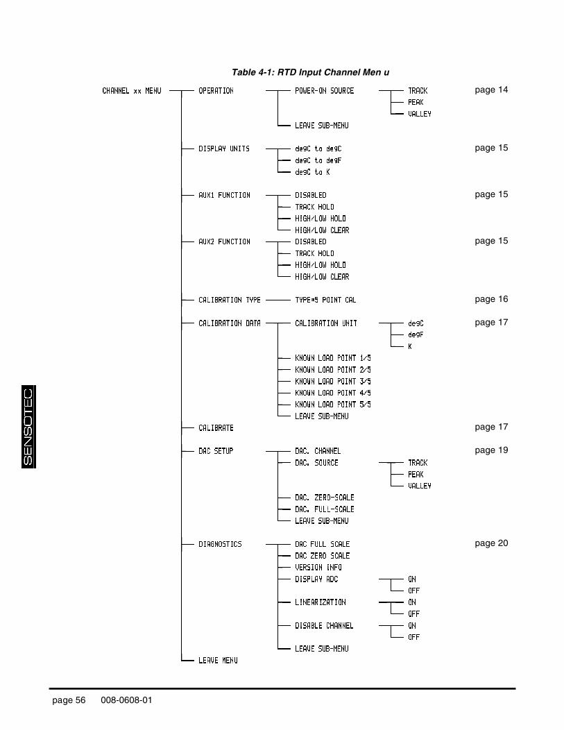
Table 4-1: RTD Input Channel Men u
CCCCHHHHAAAANNNNNNNNEEEELLLL xx MExx MExx MExx MENNNNUUUU OOOOPPPPEEEERRRRAAAATTTTIIIIOOOONNNN PPPPOOOOWWWWEEEERRRR----OOOONNNN SOURCSOURCSOURCSOURCEEEE TTTTRRRRAAAACCCCKKKK page 14
PPPPEEEEAAAAKKKK
VVVVAAAALLLLLLLLEEEEYYYY
LLLLEEEEAAAAVVVVEEEE SUB-MENSUB-MENSUB-MENSUB-MENUUUU
DDDDIIIISSSSPPPPLLLLAAAAYYYY UNIUNIUNIUNITSTSTSTS ddddeeeeggggCCCC to dto dto dto deeeeggggCCCC page 15
ddddeeeeggggCCCC to dto dto dto deeeeggggFFFF
ddddeeeeggggCCCC tttto Ko Ko Ko K
AAAAUUUUXXXX1111 FUNCTIFUNCTIFUNCTIFUNCTIONONONON DDDDIIIISSSSAAAABBBBLLLLEEEEDDDD page 15
TTTTRRRRAAAACCCCKKKK HOLHOLHOLHOLDDDD
HHHHIIIIGGGGHHHH////LLLLOOOOWWWW HOHOHOHOLDLDLDLD
HHHHIIIIGGGGHHHH////LLLLOOOOWWWW CLEACLEACLEACLEARRRR
AAAAUUUUXXXX2222 FUNCTIFUNCTIFUNCTIFUNCTIONONONON DDDDIIIISSSSAAAABBBBLLLLEEEEDDDD page 15
TTTTRRRRAAAACCCCKKKK HOLHOLHOLHOLDDDD
HHHHIIIIGGGGHHHH////LLLLOOOOWWWW HOHOHOHOLDLDLDLD
HHHHIIIIGGGGHHHH////LLLLOOOOWWWW CLEACLEACLEACLEARRRR
CCCCAAAALLLLIIIIBBBBRRRRAAAATITITITIOOOONNNN TYPTYPTYPTYPEEEE TTTTYYYYPPPPEEEE====5555 POINT CAPOINT CAPOINT CAPOINT CALLLL page 16
CCCCAAAALLLLIIIIBBBBRRRRAAAATITITITIOOOONNNN DATDATDATDATAAAA CCCCAAAALLLLIIIIBBBBRRRRAAAATITITITIOOOONNNN UNIUNIUNIUNITTTT ddddeeeeggggCCCC page 17
ddddeeeeggggFFFF
KKKK
KKKKNNNNOOOOWWWWNNNN LOAD POINT 1/LOAD POINT 1/LOAD POINT 1/LOAD POINT 1/5555
KKKKNNNNOOOOWWWWNNNN LOAD POINT 2/LOAD POINT 2/LOAD POINT 2/LOAD POINT 2/5555
KKKKNNNNOOOOWWWWNNNN LOAD POINT 3/LOAD POINT 3/LOAD POINT 3/LOAD POINT 3/5555
KKKKNNNNOOOOWWWWNNNN LOAD POINT 4/LOAD POINT 4/LOAD POINT 4/LOAD POINT 4/5555
KKKKNNNNOOOOWWWWNNNN LOAD POINT 5/LOAD POINT 5/LOAD POINT 5/LOAD POINT 5/5555
LLLLEEEEAAAAVVVVEEEE SUB-MENSUB-MENSUB-MENSUB-MENUUUU
CCCCAAAALLLLIIIIBBBBRRRRAAAATETETETE page 17
DDDDAAAACCCC SETUSETUSETUSETUPPPP DDDDAAAACCCC.... CHANNECHANNECHANNECHANNELLLL page 19
DDDDAAAACCCC.... SOURSOURSOURSOURCECECECE TTTTRRRRAAAACCCCKKKK
PPPPEEEEAAAAKKKK
VVVVAAAALLLLLLLLEEEEYYYY
DDDDAAAACCCC.... ZERO-SCALZERO-SCALZERO-SCALZERO-SCALEEEE
DDDDAAAACCCC.... FULL-SCALFULL-SCALFULL-SCALFULL-SCALEEEE
LLLLEEEEAAAAVVVVEEEE SUB-MENSUB-MENSUB-MENSUB-MENUUUU
DDDDIIIIAAAAGGGGNNNNOOOOSSSSTTTTIIIICCCCSSSS DDDDAAAACCCC FULL SCFULL SCFULL SCFULL SCALALALALEEEE page 20
DDDDAAAACCCC ZERO SCZERO SCZERO SCZERO SCALALALALEEEE
VVVVEEEERRRRSSSSIIIIOOOONNNN INFINFINFINFOOOO
DDDDIIIISSSSPPPPLLLLAAAAYYYY AAAADCDCDCDC OOOONNNN
OOOOFFFFFFFF
LLLLIIIINNNNEEEEAAAARRRRIIIIZZZZAAAATITITITIOOOONNNN OOOONNNN
OOOOFFFFFFFF
DDDDIIIISSSSAAAABBBBLLLLEEEE CHANNECHANNECHANNECHANNELLLL OOOONNNN
OOOOFFFFFFFF
LLLLEEEEAAAAVVVVEEEE SUB-MENSUB-MENSUB-MENSUB-MENUUUU
LLLLEEEEAAAAVVVVEEEE MENMENMENMENUUUU
page 56 008-0608-01

S
ET
UP
ME
NU
RE
FE
RE
NC
E4
Table 4-2: Frequency Input Channel Menu
CCCCHHHHAAAANNNNNNNNEEEELLLL xx MExx MExx MExx MENNNNUUUU OOOOPPPPEEEERRRRAAAATTTTIIIIOOOONNNN PPPPOOOOWWWWEEEERRRR----OOOONNNN SOURCSOURCSOURCSOURCEEEE TTTTRRRRAAAACCCCKKKK page 38 PPPPEEEEAAAAKKKK
VVVVAAAALLLLLLLLEEEEYYYY
LLLLEEEEAAAAVVVVEEEE SUB-MENSUB-MENSUB-MENSUB-MENUUUU
AAAAUUUUXXXX1111 FUNCTIFUNCTIFUNCTIFUNCTIONONONON DDDDIIIISSSSAAAABBBBLLLLEEEEDDDD page 38
TTTTRRRRAAAACCCCKKKK HOLHOLHOLHOLDDDD
HHHHIIIIGGGGHHHH////LLLLOOOOWWWW HOHOHOHOLDLDLDLD
HHHHIIIIGGGGHHHH////LLLLOOOOWWWW CLEACLEACLEACLEARRRR
AAAAUUUUXXXX2222 FUNCTIFUNCTIFUNCTIFUNCTIONONONON DDDDIIIISSSSAAAABBBBLLLLEEEEDDDD page 38
TTTTRRRRAAAACCCCKKKK HOLHOLHOLHOLDDDD
HHHHIIIIGGGGHHHH////LLLLOOOOWWWW HOHOHOHOLDLDLDLD
HHHHIIIIGGGGHHHH////LLLLOOOOWWWW CLEACLEACLEACLEARRRR
CCCCAAAALLLLIIIIBBBBRRRRAAAATITITITIOOOONNNN TYPTYPTYPTYPEEEE TTTTYYYYPPPPEEEE====5555 POINT CAPOINT CAPOINT CAPOINT CALLLL page 39 CCCCAAAALLLLIIIIBBBBRRRRAAAATITITITIOOOONNNN DATDATDATDATAAAA CCCCAAAALLLLIIIIBBBBRRRRAAAATITITITIOOOONNNN UNIUNIUNIUNITTTT ddddeeeeggggCCCC page 40 ddddeeeeggggFFFF
KKKK
KKKKNNNNOOOOWWWWNNNN LOAD POINT 1/LOAD POINT 1/LOAD POINT 1/LOAD POINT 1/5555
KKKKNNNNOOOOWWWWNNNN LOAD POINT 2/LOAD POINT 2/LOAD POINT 2/LOAD POINT 2/5555
KKKKNNNNOOOOWWWWNNNN LOAD POINT 3/LOAD POINT 3/LOAD POINT 3/LOAD POINT 3/5555
KKKKNNNNOOOOWWWWNNNN LOAD POINT 4/LOAD POINT 4/LOAD POINT 4/LOAD POINT 4/5555
KKKKNNNNOOOOWWWWNNNN LOAD POINT 5/LOAD POINT 5/LOAD POINT 5/LOAD POINT 5/5555
LLLLEEEEAAAAVVVVEEEE SUB-MENSUB-MENSUB-MENSUB-MENUUUU
CCCCAAAALLLLIIIIBBBBRRRRAAAATETETETE page 40
DDDDAAAACCCC SETUSETUSETUSETUPPPP DDDDAAAACCCC.... CHANNECHANNECHANNECHANNELLLL page 41
DDDDAAAACCCC.... SOURSOURSOURSOURCECECECE TTTTRRRRAAAACCCCKKKK
PPPPEEEEAAAAKKKK
VVVVAAAALLLLLLLLEEEEYYYY
DDDDAAAACCCC.... ZERO-SCALZERO-SCALZERO-SCALZERO-SCALEEEE
DDDDAAAACCCC.... FULL-SCALFULL-SCALFULL-SCALFULL-SCALEEEE
LLLLEEEEAAAAVVVVEEEE SUB-MENSUB-MENSUB-MENSUB-MENUUUU
DDDDIIIIAAAAGGGGNNNNOOOOSSSSTTTTIIIICCCCSSSS DDDDAAAACCCC FULL SCFULL SCFULL SCFULL SCALALALALEEEE page 42
DDDDAAAACCCC ZERO SCZERO SCZERO SCZERO SCALALALALEEEE
VVVVEEEERRRRSSSSIIIIOOOONNNN INFINFINFINFOOOO
DDDDIIIISSSSPPPPLLLLAAAAYYYY AAAADCDCDCDC OOOONNNN
OOOOFFFFFFFF
LLLLIIIINNNNEEEEAAAARRRRIIIIZZZZAAAATITITITIOOOONNNN OOOONNNN
OOOOFFFFFFFF
DDDDIIIISSSSAAAABBBBLLLLEEEE CHANNECHANNECHANNECHANNELLLL OOOONNNN
OOOOFFFFFFFF
LLLLEEEEAAAAVVVVEEEE SUB-MENSUB-MENSUB-MENSUB-MENUUUU
LLLLEEEEAAAAVVVVEEEE MENMENMENMENUUUU
Additional Channels for SC Series Instrumentation page 57

page 58 008-0608-01

IN
DE
X
Index
CCommunications Guide 6Customer Information Sheet 6
FFrequency Input channel
Analog Output 41–44Auxilliary Function pins 38, 44calibration 36communication commands 45features 33frequency response 37Getting Started Quickly 33remote control of Track/Hold, Peak/Valley clear,
Peak/Valley hold 38SETUP menu 38software revision 42specifications 37step response 37troubleshooting 44wiring 34
RRTD Input channel
Analog Output 19, 21–22Auxilliary Function pins 15, 22calibration 12communication commands 23display
OVLD message 22units of measure 15
features 9frequency response 13getting started quickly 9remote control of Track/Hold, Peak/Valley clear,
Peak/Valley hold 15SETUP Menu 14software revision 20specifications 13step response 13troubleshooting 22wiring 10
SSerial Communications Guide 6
Additional Channels for SC Series Instrumentation page 59

page 60 008-0608-01

W
AR
RA
NT
Y/R
EP
AIR
PO
LIC
Y
W arranty/Repair Policy
Limitation of Remedy andDisclaimer of Warranty
Any of our products which, under normal operating conditions, proves defective inmaterial or in workmanship within one year from the date of shipment by Senso-tec, Inc., will be repaired or replaced free of charge, provided that the buyer (1)promptly notifies Sensotec, Inc. of any such defect; (2) provides Sensotec, Inc.with satisfactory proof of the defect and that the product was properly installed,maintained, and operated within the limits of rated and normal usage; and (3)obtains from Sensotec, Inc. authorization to return the product. Any such productshall be returned with transportation charges prepaid. The replacement productwill be shipped F.O.B. our plant.
The remedy set forth herein does not extend to any product or part thereof which,under normal usage, has an inherently shorter useful life than one year. The rem-edy set forth herein does not apply to damage or to defects in any product causedby the buyer’s misuse or neglect, nor does it apply to any product which has beenrepaired or disassembled which, in the sole judgement of Sensotec, Inc. affectsthe performance of the product.
The remedy set forth herein is the buyer's exclusive remedy, and will satisfy allobligations of Sensotec, Inc. whether based on contract, negligence, or otherwise.Sensotec, Inc. is not responsible for any incidental or consequential loss or dam-age which might result from a failure of any Sensotec, Inc. product.
THIS EXPRESS WARRANTY IS MADE IN LIEU OF ANY AND ALL OTHERWARRANTIES, EXPRESSED OR IMPLIED, INCLUDING IMPLIED WARRANTYOF MERCHANTABILITY OR FITNESS FOR PARTICULAR PURPOSE.
Obtaining Service UnderWarranty
Advanced authorization is required prior to the return to Sensotec, Inc. Beforereturning the items, either write to the Repair Department c/o Sensotec, Inc., 2080Arlingate Lane, Columbus, Ohio 43228, or call (800) 848-6564 with: 1) a partnumber; 2) a serial number of the defective product; 3) a technical description* ofthe defect; 4) a no-charge purchase order number (so products can be returned toyou correctly); and 5) ship and bill addresses. Shipment to Sensotec, Inc. shall beat Buyer's expense and repaired or replacement items will be shipped F.O.B. ourplant in Columbus, Ohio. Non-verified problems or defects may be subject to anevaluation charge. Please return the original calibration data with the unit.
Obtaining Non-warrantyService
Advance authorization is required prior to the return to Sensotec, Inc. Beforereturning the item, either write to the Repair Department c/o Sensotec, Inc., 2080Arlingate Lane, Columbus, Ohio 43228, or call (800) 848-6564 with: 1) a partnumber; 2) a serial number of the defective product; 3) a technical description* ofthe malfunction; 4) a purchase order number to cover Sensotec, Inc.'s repair cost;and 5) ship and bill addresses. After the product is evaluated by Sensotec, Inc.,we will contact you to provide the estimated repair costs before proceeding. Theminimum evaluation charge is $95. Shipment to Sensotec, Inc. shall be at Buyer'sexpense and repaired items will be shipped to you F.O.B., our plant in Columbus,Ohio. Please return the original calibration data with the unit.
Repair Warranty All repairs of Sensotec, Inc. products are warranted for a period of 90 days fromdate of shipment. This warranty applies only to those items which were founddefective and repaired. It does not apply to products in which no defect was foundand returned as is or merely re-calibrated. Out of warranty products may not becapable of being returned to the exact original specifications or dimensions.*Technical description of the defect: In order to properly repair a product, it is necessary forSensotec, Inc. to receive information specifying the reason the product is being returned.Specific test data, written observations on the failure and specific corrective action yourequire is needed.
Additional Channels for SC Series Instrumentation page 61

(800)848-65642080 Arlingate Lane
Columbus, Ohio 43228Tel: (614)850-5000Fax: (614)850-1111
E-mail: [email protected]://www.sensotec.com