AdderLink AV100 series · Transmitter cascading ... Introduction The AdderLink AV range of digital...
26
AdderLink AV100 series Digital Signage Extenders TRANSMITTER LINK 2 LINK 3 LINK 4 104 ADDERLINK IN IN
Transcript of AdderLink AV100 series · Transmitter cascading ... Introduction The AdderLink AV range of digital...

AdderLink AV100 seriesDigital Signage Extenders
TRANSMITTER
LINK2
LINK3
LINK4
104
ADDERLINK
IN
IN

1
SECT 1
Contents
WelcomeIntroduction .................................................................................2
Standard AdderLink AV models .............................................2
Support for DDC (Display Data Channel) ..............................3
Further expansion ...................................................................4
Transmitter cascading ........................................................4
Receiver cascading .............................................................4
What’s in the box ........................................................................5
What you may additionally need ...............................................5
Module features ..........................................................................6
InstallationLocations ......................................................................................7
Mounting .....................................................................................8
Using the self adhesive feet ...................................................8
Using the rear mounting slot .................................................8
Using the optional rack mount chassis ..................................9
Making standard connections ..................................................10
Connections at the transmitter ............................................10
Connections at the receiver .................................................13
Making cascade connections ....................................................15
Important limitations when cascading ................................15
Cascade connection examples ..............................................15
Cascading transmitters .........................................................16
Cascading receivers (AdderLink AV101 only) ......................17
OperationIndicators....................................................................................18
Adjustments ...............................................................................18
Brightness and sharpness adjustments ................................18
Skew compensation adjustments (AV101 only) ..................19
Further informationTroubleshooting ........................................................................21
Getting assistance ......................................................................21
Safety information ....................................................................22
Warranty ....................................................................................22
Products in the AdderLink AV range ........................................23
Cables .........................................................................................23
Emissions and Immunity ............................................................24

2
SECT 2
WelcomeIntroduction
The AdderLink AV range of digital signage extenders are designed and built specifically for use wherever high quality video and sound must be faithfully reproduced at distant locations. Mindful of the need for variety and flexibility to suit disparate installations, Adder have created a family of products that can fulfil your current requirements and be easily expanded at any future stage.
Standard AdderLink AV100 modelsThere are three different AdderLink AV100 series transmitter and receiver module types available, the choice of each depends upon the quantity and types of devices that need to be driven:
AdderLink AV100 pairThe AdderLink AV100 package provides a single transmitter and single receiver capable of directly supporting two remote display and speaker sets. The transmitter can additionally support a local monitor and speaker set located adjacent to the source system. Expansion is made possible by connecting further AV100 transmitters to the original module, each supporting their own AV100 receiver modules. The AV100 transmitter and receiver modules are also available separately and are known as the AV100T and AV100R respectively.
AdderLink AV104 and AV101 (or AV100)The AdderLink AV104 transmitter and multiple AV101 modules are designed to provide potentially enormous expansion possibilities from the outset. Each AV104 transmitter is capable of directly feeding up to four AV101 receivers. Each receiver supports two remote display and speakers sets, but additionally can also drive a further three receivers and their respective displays/speakers. Additional expansion is also possible by connecting further AV104 transmitters to the original module, each supporting their own multiple AV101 receiver modules.
RECEIVER
RECEIVER
RECEIVER
VIDEOCATx LINKS UP TO 300m
AUDIO
POWER POWER
PC
TRANSMITTER RECEIVER
101
101
101
101
104
VIDEO
CATx LINK
UP TO 300m
AUDIO
POWER POWER
PC
TRANSMITTER
100 100
RECEIVER
AdderLink AV100 transmitter and receiver pair driving two remote displays and speakers in addition to a local monitor and speaker set
AdderLink AV104 transmitter and four AV101 (or AV100) receivers driving up to eight remote displays and speakers in addition to a local monitor and speaker set

3
Support for DDC (Display Data Channel)The Display Data Channel standard allows video monitors to define their characteristics so that the source computers to which they are connected can optimise their video outputs accordingly. By their nature, the AdderLink AV extenders enable multiple video displays to be attached to a single source computer. This causes a complication for handling the DDC standard, however, in characteristic style we have devised an elegant solution, as detailed below.
Whenever an AdderLink AV transmitter is powered on, it checks its local video port for a working display monitor with DDC information. The following strictly ordered actions occur to automatically locate the most suitable DDC data:
• Ifadisplaymonitorisdiscoveredonthelocalvideoportofthetransmitter,the DDC data are cloned from it and stored within the transmitter.
• Ifnodisplaymonitorisdiscoveredonthelocalvideoportofthetransmitter,the DDC data held within the transmitter will remain unchanged.
• IftheDDCdataorclocklinesofthetransmitter’slocalvideoportarediscovered to be connected to ground, then a default set of DDC data will be reloaded and used.
After the initial search period, the stored DDC data are then presented to the video port of the source computer. When transmitters are cascaded, only the primary transmitter (the one connected to the source computer) will perform the search for DDC data.
AdderLink AV transmitters hold two pages of DDC data in order to support the most advanced display monitors. The DDC data are held within non-volatile memory so that they are retained when power is removed.
Themannerinwhichthetransmitterssearchforsuitable‘DDCdonors’could have an impact if your installation contains display units with differing capabilities. Generally, you should arrange for the display monitor with the most representative capabilities of your whole installation to be the one that the transmitter locates on its local port, either initially (and temporarily) while commissioning or permanently.
4
Further expansion
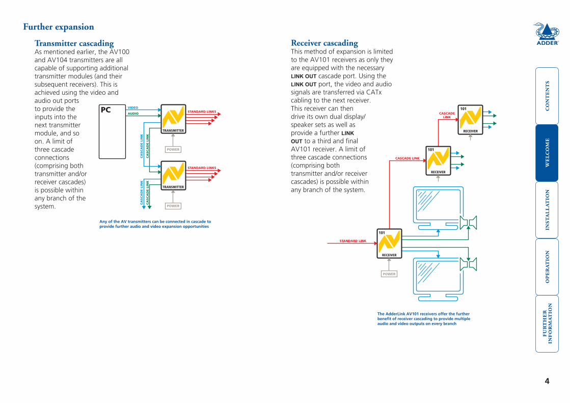
Transmitter cascadingAs mentioned earlier, the AV100 and AV104 transmitters are all capable of supporting additional transmitter modules (and their subsequent receivers). This is achieved using the video and audio out ports to provide the inputs into the next transmitter module, and so on. A limit of three cascade connections (comprising both transmitter and/or receiver cascades) is possible within any branch of the system.
VIDEO
CA
SC
AD
E L
INK
CA
SC
AD
E L
INK
STANDARD LINKS
STANDARD LINKS
AUDIO
CA
SC
AD
E L
INK
CA
SC
AD
E L
INK
POWER
POWER
PC
TRANSMITTER
TRANSMITTER
STANDARD LINK
CASCADE LINK
CASCADELINK
POWER
RECEIVER
RECEIVER
RECEIVER
101
101
101
Receiver cascadingThis method of expansion is limited to the AV101 receivers as only they are equipped with the necessary LINK OUT cascade port. Using the LINK OUT port, the video and audio signals are transferred via CATx cabling to the next receiver. This receiver can then drive its own dual display/speaker sets as well as provide a further LINK OUT to a third and final AV101 receiver. A limit of three cascade connections (comprising both transmitter and/or receiver cascades) is possible within any branch of the system.
Any of the AV transmitters can be connected in cascade to provide further audio and video expansion opportunities
The AdderLink AV101 receivers offer the further benefit of receiver cascading to provide multiple audio and video outputs on every branch

5
For each AV module: Power supply adapter and country-specific mains cable
Self adhesive rubber feet
Video cable to connect a transmitter to the source PC and optionally to connect additional transmitter modules in cascade.
Adder P/N: VSC18
RECEIVER
BRIGHTSHARP
100
ADDERLINK
OUT
OUT
TRANSMITTER
ADDERLINK
IN
IN
100
What’s in the box What you may additionally need
AdderLink AV transmitter*
AdderLink AV receiver*
* AdderLink AV100 models are
packaged as transmitter and receiver pairs. AV104, AV101, AV100R
and AV100T modules are packaged separately.
Stereo audio cable to connect a transmitter to the source PC and optionally to connect additional transmitter modules in cascade.
Adder P/N: VSC22
CD-ROM containing skew test pattern and documentation
For part numbers of other items, please also refer to the section Products in the AdderLink AV range.
< Rack mount fascia plate for modules.
Adder P/N: ALAV-RMK-FASCIA
19” rack mount chassis >Adder P/N: ALAV-RMK-CHASSIS

6
RECEIVER
SKEWGB
SKEWRG
BRIGHTSHARP
LINK OUT
101
ADDERLINK
OUT
OUT
Module features
TRANSMITTER
LINK2
LINK3
LINK4
104
ADDERLINK
IN
IN
Transmitter module(AV104 model pictured)
Power supply connection
Local video output Local
audio output
Video input from source PC
Audio input from source PC
Link output to receiver 1
Link outputs to receivers 2, 3 & 4 (AV104 only)
Indicators
Receiver module(AV101 model pictured)
Power supply connection
Link output to cascaded receiver (AV101 only)
Indicators
Link input from transmitter (or cascade input)
Audio output to speakers
Video output to display
Audio output to speakers
Video output to display
Variation for AV100 transmitter
Single link out connector
Brightness control
Sharpness control
Skew adjusters (not AV100)
Variation for AV100 receiver
Single link in connector
(also no skew compensation adjusters)

7
InstallationLocations
Please consider the following important points when planning the positions of your AdderLink AV modules:
• Takecarenottoexceedthemaximumlinkcablelengths(pleaserefertothesection Making cascade connections).
• EnsurethatthetransmittersareascloseaspossibletothesourcePCsystemand the receivers are similarly close to the display modules. Use video connection cables that are correctly shielded and are no longer than 6m in length.
• Whereverpossible,chooseroutesfortheCATxtwistedpairlinkcablesthatavoid mains power cables.
• Rememberamainspowersocketisrequiredforeachtransmitterandreceiver.
• ConsulttheprecautionslistedwithintheSafety information section.
SECT 3
8
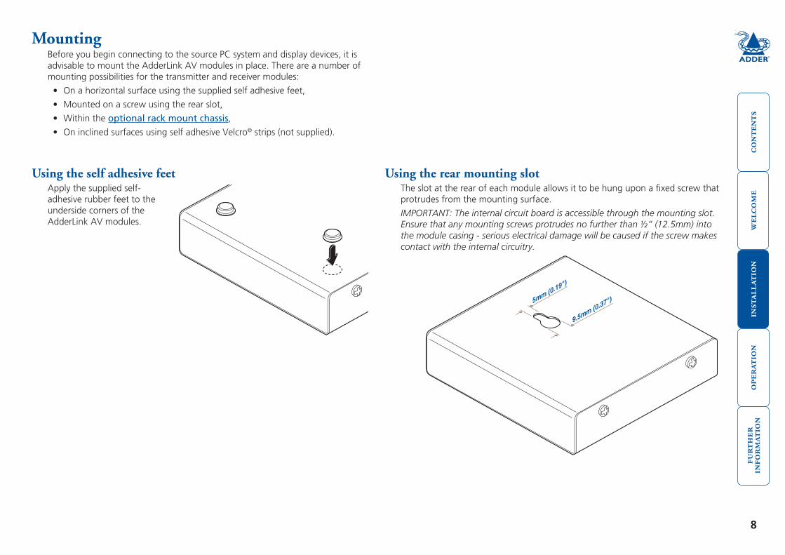
Using the rear mounting slotThe slot at the rear of each module allows it to be hung upon a fixed screw that protrudes from the mounting surface.
IMPORTANT: The internal circuit board is accessible through the mounting slot. Ensure that any mounting screws protrudes no further than ½” (12.5mm) into the module casing - serious electrical damage will be caused if the screw makes contact with the internal circuitry.
5mm ()
0.19"
9.5mm0.37"
()
Using the self adhesive feetApply the supplied self-adhesive rubber feet to the underside corners of the AdderLink AV modules.
MountingBefore you begin connecting to the source PC system and display devices, it is advisable to mount the AdderLink AV modules in place. There are a number of mounting possibilities for the transmitter and receiver modules:
• Onahorizontalsurfaceusingthesuppliedselfadhesivefeet,
• Mountedonascrewusingtherearslot,
• Withintheoptional rack mount chassis,
• OninclinedsurfacesusingselfadhesiveVelcro© strips (not supplied).

9
Using the optional rack mount chassis1 Place the optional rack plate onto the front of the transmitter or receiver
module and secure it with the countersunk screws.
2 Orientthemoduleonitssidesothatitslabelledfaceisthecorrectwayupand the securing plate is facing away from the rack.
3 Slide the module into the required rack position.
4 The rack mount chassis has a series of holes in its floor that are spaced to accommodatethescrewsonthemodule’sloweredge.Ensurethatthescrews correctly locate into the holes of the chosen slot. The rack securing plate on the module should now be flush with the front of the rack mount chassis.
5 Use the supplied (pan-head) screws, in the top hole of the rack securing plate to fasten the module to the rack.
TRANSMITTER
LIN
K2
LIN
K3
LIN
K4
104
ADDERLINKIN
IN

10
Making standard connectionsConnections to the AdderLink AV modules do not need to follow the precise order given in this user guide although it is recommended that you do not apply power to the modules until all other connections have been made.
Note: Unless stated otherwise, all connection information given here applies to all modules in the AdderLink AV family.
Connections at the transmitter
To connect video and audio from the source PC system1 Attach a video cable of suitable type and length (fully shielded with 15 way
male D-type connectors at both ends, 2m or less - Adder part number: VSC18) to the socket labelled
IN on the AdderLink AV transmitter.
2 Attach the other end of the video cable to the appropriate VGA video output socket on the source PC system.
3 Attach a stereo audio cable (shielded with three way 3.5mm jack plugs at both ends - Adder part number: VSC22) to the socket labelled
IN on
the AdderLink AV transmitter.
4 Attach the other end of the stereo audio cable to the appropriate audio output socket on the source PC system.
To connect a monitor and speakersThe video and audio out ports of the AdderLink AV transmitter can optionally be used either to:
• Attachamonitorand/orspeakersinthevicinityofthesourcePCsystem–See below,
or
• Makeacascadelinktoanothertransmittermodule–Pleaserefertothesection Making cascade connections – Cascading transmitters.
1 Attach the video cable from the monitor to the socket labelled OUT
on the AdderLink AV transmitter.
2 Attach the stereo audio cable from the speakers to the socket labelled
OUT on the AdderLink AV
transmitter.
TRANSMITTER
LINK2
LINK3
LINK4
104
ADDERLINK
IN
IN
TRANSMITTER
LINK2
LINK3
LINK4
104
ADDERLINK
IN
IN

11
To connect the link cable(s)The links between the transmitter and receiver modules are made using between one and four twisted pair cables, specified to Category 5 or higher. Each cable carries video and audio signals to each receiver module.
When a single receiver is attached to a link cable, the maximum length of that link cable is 300m (1000 feet).
AdderLink AV104 models1 Attach the connector of the first link cable to the socket
labelled L1 OUT on the AdderLink AV104 transmitter. There should be a click when the cable is fully inserted and locked in place.
2 Attach the connectors of the remaining link cables to the sockets labelled L2 OUT to L4 OUT, as required.
Inallcases,thereshouldbea click when the cable is fully inserted and locked in place.
TRANSMITTER
ADDERLINK
IN
IN
100
TRANSMITTER
LINK 2
LINK 3
LINK 4
104
ADDERLINK
IN
IN
RECEIVERTRANSMITTER
Overall maximum link length: 300m
STANDARD LINK
However, if further receivers are connected in cascade to the initial receiver using its LINK OUT port (AdderLink AV101 models only), then the overall length of the link cables used must be reduced. For further information, please refer to the section Making cascade connections.
NOTE: Where possible, avoid laying the twisted pair link cable(s) alongside power cables.
AdderLink AV100 models1 Attach the connector of the link cable to the socket labelled
LINK on the AdderLink AV100 transmitter. There should be a click when the cable is fully inserted and locked in place.

12
To connect the power supplyNOTE: Please read and adhere to the electrical safety information given within the Safety information section of this guide. In particular, do not use an unearthed power socket or extension cable.
1 Attach the output connector of the power supply to the socket labelled POWER on the AdderLink AV transmitter.
2 InserttheIECconnectorofthepowercableinto the corresponding socket of the power supply.
3 When all other connections have been made at the transmitter and receiver modules, connect the other end of the power cable to a nearby earthed mains socket.
TRANSMITTER
ADDERLINK
IN
IN
100

13
Link inThe link from the transmitter to each receiver module is made using a twisted pair cable, specified to Category 5 or higher.
When a single receiver is attached to a link cable, the maximum length of that link cable is 300 metres (1000 feet).
RECEIVER
SKEWGB
SKEWRG
BRIGHTSHARP
LINK OUT
101
ADDERLINK
OUT
OUT
RECEIVERTRANSMITTER
Overall maximum link length: 300m
STANDARD LINK
However, if further receivers are connected in cascade to the initial receiver (using the LINK OUTport–AdderLinkAV101modulesonly),thentheoveralllength of the link cables used must be reduced. For further information, please refer to the section Making cascade connections.
NOTE: Where possible, avoid laying the twisted pair link cable(s) alongside power cables.
1 Attach the connector of the link cable to the socket labelled LINK IN on the AdderLink AV receiver. There should be a click when the cable is fully inserted and locked in place.
Connections at the receiver
To connect displays and speakersDual video and audio outputs are provided on the AdderLink AV receiver. Both sets of ports provide identical signals and their connection procedures are the same:
1 Attach the video cable from the display module to the socket labelled
OUT on the AdderLink AV receiver.
2 Attach the stereo audio cable from the speakers (or amplifier) to the socket labelled
OUT on the AdderLink AV
receiver.
RECEIVER
SKEWGB
SKEWRG
BRIGHTSHARP
LINKOUT
101
ADDERLINK
OUT
OUT

14
To connect the power supplyNOTE: Please read and adhere to the electrical safety information given within the Safety information section of this guide. In particular, do not use an unearthed power socket or extension cable.
1 Attach the output connector of the power supply to the socket labelled POWER on the AdderLink AV receiver.
2 InserttheIECconnectorofthepowercableintothe corresponding socket of the power supply.
3 When all other connections have been made at the transmitter and receiver modules, connect the other end of the power cable to a nearby earthed mains socket.
RECEIVER
SKEWGB
SKEWRG
BRIGHTSHARP
LINK OUT
101
ADDERLINK
OUT
OUT

15
Making cascade connectionsThe AdderLink AV series of products have been specifically designed to be flexible in order to support both your immediate and future needs for media streaming.Inadditiontothestandardconnectionsmadefromtransmitterstoreceivers, you can also link extra transmitters to transmitters and/or receivers to receivers in order to provide more display/speaker outputs. These non-standard links are called cascade connections.
Important limitations when cascading• Thereshouldneverbemorethanthreecascadeconnectionsbetweenthe
primary transmitter (the one connected to the source PC) and any receiver. The cascade connections can all occur at the transmitter end or all at the receiver end (AV101 modules only) or at a mixture of both.
• Eachcascadeconnectionreducestheoveralllinklengthpermissiblefromatransmitter to the final receiver in a branch. To calculate the recommended overall maximum link length for a branch, count the number of cascade connections between the primary transmitter and the final receiver in that branch. The effects of cascade connections on overall branch link lengths are as follows:
Number of cascade connections Overall length of links for a branch (in a branch) (from transmitter to furthest receiver)
0 300m (1000 feet)
1 250m (800 feet)
2 200m (650 feet)
3 175m (600 feet)
Notes The lengths of transmitter cascade (video) connections should never be
longer than 2m (6 feet) and can be considered to have a negligible effect upon overall link lengths.
Themaximumresolutionsachievableare:1600x1200x60Hzat200mand1280x1024x60Hzat300m.Ifyouareusinglowerresolutionsthenitmay be possible to achieve longer transmission distances than shown in the above table although we do not recommend runs longer than 300m in any installation.Ifyouarerunningshortercablesthenitmaybepossibletousemore cascades than shown in the above table.
Cascade connection examplesThese examples demonstrate valid configurations and the effect of cascade connections upon overall link lengths:
RECEIVER
RECEIVER
RECEIVER
TRANSMITTER
Overall maximum length for link with no cascades: 300m
Overall maximum length for link with 1 cascade: 250m
Cascade 1Branch 1
Branch 2STANDARD LINK
STANDARD LINK
RECEIVER
RECEIVER
RECEIVER
RECEIVER
RECEIVER
RECEIVER
RECEIVER
RECEIVER
RECEIVER
PrimaryTransmitter
TRANSMITTER
TRANSMITTER
TRANSMITTER
Cascade 1
Cascade 2
Cascade 2
Cascade 3
Cascade 3
From PC
Branch 1
Branch 2
Branch 3
Overall maximum length for link with 3 cascades: 175m
Cascade 1
Cascade 3
Cascade 2
STANDARD LINK
STANDARD LINK
STANDARD LINK

16
Cascading transmittersExpansion at the transmitter end is achieved using the video and audio output ports. The signals from these ports are connected to the video and audio inputs of the next transmitter and so on. AdderLink AV100 and AV104 transmitters can be mixed in a cascade in any order using the method discussed here.
NOTE: Ensure that there are no more than three cascades (transmitter or receiver cascades) between the primary transmitter and the furthest receiver in any branch.
CA
SC
AD
E L
INK
CA
SC
AD
E L
INK
STANDARD LINKS
STANDARD LINKS
CA
SC
AD
E L
INK
CA
SC
AD
E L
INK
VIDEO
AUDIO
POWER
POWER
PC
TRANSMITTER
TRANSMITTER
PrimaryTransmitter
To connect cascaded transmitters1 Attach a video cable of suitable type and length (fully shielded with
15 way male D-type connectors at both ends, 2m or less - Adder part number: VSC18) to the socket labelled
OUT on the primary AdderLink AV
transmitter.
2 Attach the other end of the video cable to the socket labelled
IN on the secondary AdderLink AV transmitter.
3 Attach a stereo audio cable (shielded with three way 3.5mm jack plugs at both ends - Adder part number: VSC22) to the socket labelled
OUT on
the primary AdderLink AV transmitter.
4 Attach the other end of the stereo audio cable to the socket labelled
IN on the
secondary AdderLink AV transmitter.
5 Repeat such cascade links until the required number of transmitters (up to a maximum of four) are present. Connect the remaining signal and power cables to the added transmitters (and their respective receivers) as discussed earlier within this chapter.
TRANSMITTER
LINK2
LINK3
LINK4
104
ADDERLINK
IN
IN
TRANSMITTER
LINK2
LINK3
LINK4
104
ADDERLINK
IN
IN
Primary transmitter
Secondary transmitter

17
Cascading receivers (AdderLink AV101 only)Expansion at the receiver end is made possible using the LINK OUT ports present on AdderLink AV101 receivers. Receiver cascade links are made using twisted pair cables, specified to Category 5 or higher.
NOTE: Ensure that there are no more than three cascades (transmitter or receiver cascades) between the primary transmitter and the furthest receiver in any branch.
RECEIVER
101
STANDARDLINK
CASCADE LINK
CASCADE LINK
POWER
RECEIVER
RECEIVER
101
101
PrimaryReceiver
Video image adjustmentsAs link cable lengths increase and more receivers are cascaded, colour separation effects may become noticeable within displayed video images, particularly at higher resolutions. Theseeffectsarecalled‘skew’and result from differing delays on the red, green and blue colour signals as they travel to the receivers. Each AdderLink AV101 receiver provides two extra adjustment dials to counter skew effects. For further information, please refer to the section Skew compensation adjustments.
RECEIVER
SKEWGB
SKEWRG
BRIGHTSHARP
LINK OUT
101
ADDERLINK
OUT
OUT
RECEIVER
SKEWGB
SKEWRG
BRIGHTSHARP
LINK OUT
101
ADDERLINK
OUT
OUT
To connect cascaded receiversNOTE: Please observe the recommended overall link cable lengths (including receiver cascade connections) in order to avoid signal degradation.
1 Attach the connector of the cascade link cable to the socket labelled LINK OUT on the primary AdderLink AV101 receiver.
2 At the other end of the cascade link cable, attach the connector to the socket labelled LINK IN on the secondary AdderLink AV101 receiver.
Inallcases,thereshouldbeaclickwhenthecableisfullyinserted and locked in place.
3 Ifnecessary,repeattheaboveprocedureforatertiaryAdderLink AV101 receiver.
4 Connect the remaining signal and power cables to the added receivers, as discussed earlier within this chapter.
Primary receiver
Secondary receiver

18
OperationInoperation,theAdderLinkAVmodulesaredesignedtobecompletelytransparent - high quality video and audio from the source PC system are played as normal, the only difference is that they are now being seen and heard up to 300 metres away.
IndicatorsAll AdderLink AV modules are equipped with two indicators to confirm operation and, if necessary, assist with quick troubleshooting of potential problems.
The indicators are located on one of the end panels, near to the LINK port and operate as follows:
• RED When lit, indicates the presence of power into the module,
• GREEN When lit, indicates the presence of a video input into the module.
LINK OUT
Brightness and sharpness adjustmentsThe brightness and sharpness adjustments provided on every AdderLink AV receiver allow you to compensate for any losses incurred within long cable links. These two adjustments can be made in any order and independently of each other.
When making adjustments it is necessary to have access to the AdderLink AV receiver and to be able to view one or both connected display screens. Both adjustments, sharpness in particular, are made easier when viewing high contrast images with vertical edges, such as black lines on a white background.
NOTE: Both video outputs are equally affected by your brightness and/or sharpness adjustments.
To display a suitable high contrast image • Openawordprocessor,typethecapital
letter‘H’,or‘M’andincreasethepointsizeto72orhigher.Forbestresults,thebackground should be white and the character should be black.
•ABLACKshadowontherightofthecharacter indicates UNDER compensation.
•AWHITEshadowontherightofthecharacterindicatesOVERcompensation.
BRIGHTSHARP
ADDERLINK
Sharpness dialBrightness dial
High contrast black character on white background
Black or bright white shadow on the right indicates the need for sharpness adjustment
To adjust brightness and/or sharpness 1 Carefully insert a small screwdriver into the dial labelled BRIGHT or SHARP, as
appropriate.
2 Slowly turn the dial clockwise or anticlockwise and observe the effect shown on the screen. Withdraw the screwdriver when the displayed image is shown at its optimum clarity.
3 Ifnecessary,repeatstep2fortheotherdial.
SECT 4
AdjustmentsVideo signals are susceptible to the effects of long distance cables and for this reason, every AdderLink AV receiver includes brightness and sharpness adjustment dials. Additionally, the AdderLink AV101 receivers are also equipped with two extra dials to eliminate the effects of colour skew within the video image.

19
Skew compensation adjustments (AV101 only)The twisted pair cabling used to link the AdderLink AV modules consists of four pairs of wires per cable. Three of these pairs are used to convey the red, green and blue video signals. Due to slight differences in twist rate between the wire pairs, the red, green and blue video signals may not arrive at precisely the same time. This effect is visible as separate colour shadows on high contrast images and is particularly apparent when using higher screen resolutions over long distances and also when using certain types of category 5e cables.
Skew compensation adjustments are made using two rotary dials, the first affects the relationship between the green and blue colour signals (SKEW GB) while the second (SKEW RG) operates similarly on the red and green signals. Each dial delays one of its stated colours in relation to the other. By using both dials it is possible to correctly align all three colours. The effects of skew are easiest to view and adjust when distinct red, green and blue elements, in close proximity, are present within the screen image. An appropriate test pattern is supplied on the AdderLink AV CD-ROMoralternativelyyoucancreateyourowntestpatternasdiscussedopposite.
NOTE: Both video outputs are equally affected by your skew adjustments.
SKEWGB
SKEWRG
BRIGHTSHARP
ADDERLINK
SKEW RG dialSKEW GB dial
To create a skew test pattern 1 Run any image creation/editing application, such as the Paint program
supplied with Windows.
2 Using the image application create three stackedhorizontalrectangles(onered,onegreen and one blue) that fill the width of the screen.
3 Draw a vertical black line down across the coloured bars and then repeat this vertical line at intervals along the width of the coloured bars. These lines create breaks across the colours and give you moreopportunitiestoviewthehorizontalposition of each colour relative to the others.
To display the supplied skew test pattern 1 InsertthesuppliedAdderCD-ROMintothe
CD player of the computer.
2 Within Windows, use the My Computer option (usually available as a desktop icon or within the Start menu) to view the contentsoftheCD-ROM.Double-clicktheSkewTest entry to display the standard test pattern.Ifnecessary,selecttheFull screen option from the File menu to maximise the application window so that the image fills the screen.
The screen will show a series of fine red, green and blue crosses which should all beinline,verticallyandhorizontally-skewaffectsthehorizontalplacementofthecolours.
1 2 3 4 5 6 7 8
8
6
5
2
8
6
5
2
Data signal
Redvideo signal
Greenvideo signal
Bluevideo signal
7
3
4
1
7
3
4
1

20
To zero the skew adjustment dialsWhen supplied, the two skew dials are set in their neutral positions. i.e. no delay to either of its colours. However, if the module has been previously used and adjusted then you mayneedtorelocatethezeropoint.Thereareno setting markers around the two skew dials and the dial itself does not have a pointer.
1 Insertasmallscrewdriverintotheskewdial and twist it all the way anticlockwise. Note the position of the dial when it reaches its end point.
2 Rotate the screwdriver fully clockwise and again note the endpoint position of the dial.
3 Now rotate the screw driver anticlockwise until the dial reaches the position that lies midway between the two end points. This is the neutral position.
4 Repeat this procedure for the other skew dial, if necessary.
0(no compensation)
Max Max
To adjust the skew compensationYour chances of achieving a successful skew compensation adjustment will be improved if you do the following:
• Ensurethatyouhaveaclearviewofoneorbothdisplayscreens,
• DisplayasuitableRGBtestpattern,eitherthesupplied pattern or a self-created version,
• Useascrewdriverofanappropriatesizetoadjustthedials,
• Beginwithbothskewdialsintheirneutralpositions-ifthemodulehasbeenpreviouslyusedandskewadjustedforanalternativeinstallation,zerothedialsasdescribedinthesection‘Tozerotheskewadjustmentdials’left.
0(no compensation)
Skew RG Skew GB0
(no compensation)
DelayRED
DelayGREEN
DelayGREEN
DelayBLUE
1 Turn the SKEW RG dial clockwise or anticlockwise until you observe that the red and green colours are aligned.
2 Turn the SKEW GB dial clockwise or anticlockwise until you observe that the green and blue colours are aligned.
3 Your actions in step 2mayaltertheRed/Greenalignment.Ifso,gobacktothe SKEW RG dial and turn it clockwise or anticlockwise until you observe that the Red and Green colours are aligned, at which point all of the colours will be aligned.

21
Further informationTroubleshooting
IfyouexperienceproblemswheninstallingorusingtheAdderLinkAVmodules,pleasecheckthroughthissectionforapossiblesolution.Ifyourproblemisnotlisted here and you cannot resolve the issue, then please refer to the ‘Getting assistance’section.
No video image is received at the receiver module.•Checkthattheboththeredpowerindicatorsarelitonboththetransmitter
and receiver modules - if they are not, then there is a power problem. Both modules require power from their supplied power adapters.
•Checkthatthegreenvideoinputindicatorsarelitonboththetransmitterand receiver modules - if one or both are not lit, then a valid video input signal is not present at the input to that module.
•Checkthelinkcable(s)thatconnectthetransmitterandreceivermodule(s)for soundness and correct wiring as per the diagram in the ‘Skew compensationadjustments’sectioninthe‘Operation’chapter.
•Ifpossible,tryusinganalternativetwistedpairlinkconnectionbetweenthemodules.
•Ifthesharpnesscontrolissettoohigh,themonitormaynotbeabletodisplay a picture. Try reducing the sharpness setting. Please refer to the ‘Adjustments’sectioninthe‘SpecialConfiguration’chapter.
•Ifnotalreadyfitted,connectamonitortotheOUT
port of the transmitter module and check for a correct video image output.
Video image at the receiver module is distorted or shadows appear to the right of displayed objects.Adjustments are required to compensate for the length of the twisted pair cable beingused.Ifvideoproblemspersist:
• Pleaserefertothe‘Brightnessandsharpnessadjustments’sectioninthe‘Operation’chapter.
• Iftheoverallvideoimageis‘fuzzy’and/orhascolouredshadowsyoumayneed to make skew adjustments (AdderLink AV101 receivers only). This procedure allows you to finely tune the red, green and blue video signal timings to overcome most colour separation problems. Please refer to the ‘Skewcompensationadjustment’sectioninthe‘Operation’chapter.
Power is applied via the power supply but the module operation has stopped.
•Eachmodulehasaninternalautomaticcut-outfusetoprotectagainstpower surges. To reset, remove power from the module for one second and then reconnect.
No sound can be heard on the speakers connected to the receiver module
•Ifnotalreadyfitted,connectspeakerstotheOUT
port of the transmitter module and check for a correct audio output.
•Checkthattheboththeredpowerindicatorsarelitonboththetransmitterand receiver modules - if they are not, then there is a power problem. Both modules require power from their supplied power adapters.
SECT 5
Getting assistanceIfyouarestillexperiencingproblemsaftercheckingtheinformationcontainedwithin this guide, then we provide a number of other solutions:
• Online solutions and updates–www.adder.com/support
Check the Support section of the adder.com website for the latest solutions and firmware updates.
• Adder Forum–forum.adder.com
Use our forum to access FAQs and discussions.
• Technical support–www.adder.com/contact-support-form
For technical support, use the contact form in the Support section of the adder.com website - your regional office will then get in contact with you.

22
Safety information• Foruseindry,oilfreeindoorenvironmentsonly.
• Donotusetolinkbetweenbuildings.
• Notsuitableforuseinhazardousorexplosiveenvironmentsornexttohighlyflammable materials.
• Ensurethatalltwistedpairinterconnectcablesareinstalledincompliancewith all applicable wiring regulations.
• DonotconnecttheCATxlinkinterface(RJ45styleconnector)toanyotherequipment, particularly network or telecommunications equipment.
• Wherepossible,avoidlayingthetwistedpairlinkcable(s)alongsidepowercables.
• Warning–thepoweradaptercontainsliveparts.
• Nouserserviceablepartsarecontainedwithinthepoweradapter-donotdismantle.
• Theprimarymeanstoceaseoperationofthemodulesistoremovethepower adapter lead. Ensure that the power adapter is positioned near to the equipment and is easily accessible.
• Donotusethepoweradapterifthepoweradaptercasebecomesdamaged,cracked or broken or if you suspect that it is not operating properly.
• Replacethepoweradapterwithamanufacturerapprovedtypeonly.
• Ifyouuseapowerextensioncablewiththemodules,makesurethetotalampere rating of the devices plugged into the extension cable do not exceed thecable’sampererating.Also,makesurethatthetotalampereratingofallthedevicespluggedintothewalloutletdoesnotexceedthewalloutlet’sampere rating.
• Donotattempttoservicethemodulesyourself.
• Themodulesandpowersuppliescangetwarminoperation–donotsituatethem in an enclosed space without any ventilation.
• Themodulesdonotprovidegroundisolationandshouldnotbeusedforany applications that require ground isolation or galvanic isolation.
• Useonlywithgroundedoutletsatboththecomputerandmonitor.Whenusing a backup power supply (UPS), power the computer, the monitor and the module from the same supply.
• Forcorrectoperation,thetransmitterandreceivermodulesmusthaveground connections. At the computer end, this is achieved by ensuring that the computer that the module is connected to has a ground connection. At the audio/visual device end, this can be achieved by ensuring that the power supply is connected to a grounded power outlet. Alternatively, a ground connection will be made via the monitor, if the monitor is itself grounded.
WarrantyAdder Technology Ltd warrants that this product shall be free from defects in workmanship and materials for a period of two years from the date of original purchase.Iftheproductshouldfailtooperatecorrectlyinnormaluseduringthewarranty period, Adder will replace or repair it free of charge. No liability can be acceptedfordamageduetomisuseorcircumstancesoutsideAdder’scontrol.Also Adder will not be responsible for any loss, damage or injury arising directly orindirectlyfromtheuseofthisproduct.Adder’stotalliabilityunderthetermsof this warranty shall in all circumstances be limited to the replacement value ofthisproduct.Ifanydifficultyisexperiencedintheinstallationoruseofthisproduct that you are unable to resolve, please contact your supplier.

23
Products in the AdderLink AV rangeThe following items are available within the AdderLink AV product range:
•AdderLink AV100 pair (part number: ALAV100P) OneAdderLinkAV100transmitterandoneAdderLinkAV100receiver.
•AdderLink AV100 transmitter (part number: ALAV100T) Single AdderLink AV100 transmitter.
•AdderLink AV100 receiver (part number: ALAV100R) Single AdderLink AV100 receiver.
•AdderLink AV104 transmitter (part number: ALAV104T) Single AdderLink AV104 transmitter.
•AdderLink AV101 receiver (part number: ALAV101R) Single AdderLink AV101 receiver.
•Replacement power supply (part number: PSU-ALAV-IEC) Oneauto-voltagesensingpowersupplywithcountryspecificIECcable
•Rack mount chassis (part number: ALAV-RMK-CHASSIS) One19”chassisis3UhighandcapableofaccommodatinguptosixteenAdderLink AV transmitter or receiver modules.
•Universal rack mount securing plate (part number: ALAV-RMK-FASCIA)
CablesThese cables are available for use when connecting the modules to systems and peripherals:
•Video cable - 2 metres (part number: VSC18)
• Audiocable-3.5metres(partnumber:VSC22)
•Serial cable - 9 way male to 9 way female D-type, 2 metres (part number: CAB-9M/9F-2M)

24
Emissions and ImmunityA Category 5 (or better) twisted pair cable must be used to connect the modules in order to maintain compliance with radio frequency energy emission regulations and ensure a suitably high level of immunity to electromagnetic disturbances.
All other interface cables used with this equipment must be shielded in order to maintain compliance with radio frequency energy emission regulations and ensure a suitably high level of immunity to electromagnetic disturbances.
European EMC directive 89/336/EECThis equipment has been tested and found to comply with the limits for a class A computing device in accordance with the specifications in the European standard EN55022. These limits are designed to provide reasonable protection against harmful interference. This equipment generates, uses and
can radiate radio frequency energy and if not installed and used in accordance with the instructions may cause harmful interference to radio or television reception. However, there is no guarantee that harmful interference will not occur inaparticularinstallation.Ifthisequipmentdoescause
interference to radio or television reception, which can be determined by turning the equipment on and off, the user is encouraged to correct the interference with one or more of the following measures: (a) Reorient or relocate the receivingantenna.(b)Increasetheseparationbetweentheequipmentandthereceiver. (c) Connect the equipment to an outlet on a circuit different from that to which the receiver is connected. (d) Consult the supplier or an experienced radio/TV technician for help.
FCC Compliance Statement (United States)This equipment generates, uses and can radiate radio frequency energy and if not installed and used properly, that is, in strict accordance with the manufacturer’sinstructions,maycauseinterferencetoradiocommunication.IthasbeentestedandfoundtocomplywiththelimitsforaclassAcomputingdeviceinaccordancewiththespecificationsinSubpartJofpart15ofFCCrules,which are designed to provide reasonable protection against such interference whentheequipmentisoperatedinacommercialenvironment.Operationofthisequipment in a residential area may cause interference, in which case the user at his own expense will be required to take whatever measures may be necessary to correct the interference. Changes or modifications not expressly approved by themanufacturercouldvoidtheuser’sauthoritytooperatetheequipment.
Canadian Department of Communications RFI statementThis equipment does not exceed the class A limits for radio noise emissions from digital apparatus set out in the radio interference regulations of the Canadian Department of Communications.
Le présent appareil numérique n’émet pas de bruits radioélectriques dépassant les limites applicables aux appareils numériques de la classe A prescrites dans le règlement sur le brouillage radioélectriques publié par le ministère des Communications du Canada.

25
www.ctxd.com Documentation by:
© 2012 Adder Technology Limited
All trademarks are acknowledged.
PartNo.MAN-ALAV•Release1.3b
Web: www.adder.com
Contact: www.adder.com/contact-details
Support: forum.adder.com