Addendum to kWh Meter Installation Instructions … Power Monitoring/PDFs/Class 2000...Addendum to...
8
Addendum to kWh Meter Installation Instructions For Use with E-MON Meters in High Voltage Applications This document is intended as a supplement to the kWh Meter Installation and Instruction Manual and is not intended to be used without it. E-MON, LLC 850 Town Center Drive Langhorne, PA (800) 334-3666 FAX: (215) 752-3094 www.emon.com E-Mail: [email protected]
Transcript of Addendum to kWh Meter Installation Instructions … Power Monitoring/PDFs/Class 2000...Addendum to...

Addendum to kWh Meter Installation Instructions For Use with E-MON Meters in High Voltage Applications
This document is intended as a supplement to the kWh Meter Installation and Instruction
Manual and is not intended to be used without it.
E-MON, LLC 850 Town Center Drive Langhorne, PA (800) 334-3666 FAX: (215) 752-3094
www.emon.com E-Mail: [email protected]

FORWARD
The E-MON model # 12025HV kWh meter is designed to be used for monitoring high voltage (2400, 4160, 13200, etc) circuits, either “stand alone” or in an AMR application. This meter is intended to be used with the appropriate high voltage Potential Transformers (PTs) and Current Transformers CTs) supplied by others. The meter application is centered around a 120 VAC secondary output from the high voltage PTs and a 5 amp secondary output from the high voltage CTs. Items addressed by this document include the installation of the 12025HV meter on high voltage circuits as well as the calculations to provide the correct meter multiplier based on the PT and CT sizes used on the high voltage conductors. Installation should be performed by qualified personnel and only according to all applicable electrical codes. E-MON Corporation or its representatives assume no responsibility for damage or injury resulting from the improper installation of this meter.

INDEX
Page 1 Current Sensor Wiring Details Page 2 Meter Wiring Page 3 Meter Multiplier Calculations
CURRENT SENSOR WIRING DETAILS
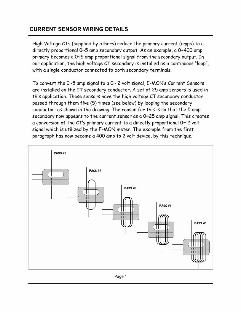
High Voltage CTs (supplied by others) reduce the primary current (amps) to a directly proportional 0~5 amp secondary output. As an example, a 0~400 amp primary becomes a 0~5 amp proportional signal from the secondary output. In our application, the high voltage CT secondary is installed as a continuous “loop”, with a single conductor connected to both secondary terminals. To convert the 0~5 amp signal to a 0~ 2 volt signal, E-MON’s Current Sensors are installed on the CT secondary conductor. A set of 25 amp sensors is used in this application. These sensors have the high voltage CT secondary conductor passed through them five (5) times (see below) by looping the secondary conductor as shown in the drawing. The reason for this is so that the 5 amp secondary now appears to the current sensor as a 0~25 amp signal. This creates a conversion of the CT’s primary current to a directly proportional 0~ 2 volt signal which is utilized by the E-MON meter. The example from the first paragraph has now become a 400 amp to 2 volt device, by this technique.
Page 1

HIGH VOLTAGE METER WIRING
Page 2
This special high voltage meter installation shows the correct wiring procedure for 3-wire high voltage circuits. In this application, the 2 element meter connection is used on the secondary circuits of the user supplied high voltage PTs and CTs. The E-MON meter used in this application is the model 12025 HV. Installation of these meters requires the use of two (2) current sensors mounted on the secondaries of the high voltage Current Transformers. See the drawing above for proper wiring. For correct operation, the meter must be installed correctly.

METER MULTIPLIER CALCULATIONS
Page 3
This special high voltage meter installation utilizes high voltage PTs (Potential Transformers) and CTs (Current Transformers) supplied by others. The E-MON meter is installed using the secondary outputs of these devices. High voltage PTs reduce the primary voltage (4160v, 13200v, etc.) to a Secondary output of 120v. This secondary is connected to the E-MON meter voltage inputs as shown in the wiring diagram. High voltage CTs reduce the primary current (amps) to a directly proportional 0~5 amp output. As an example, a 0~400 amp primary becomes a 0~5 amp proportional signal from the secondary output. This allows much smaller wiring to be utilized in the meter hookup. The high voltage CT secondary is installed as a continuous “loop”, with a single lead connected to both secondary terminals. E-MON meters accept a 0~2 volt signal from their Current Sensors. To convert the 0~5 amp signal, the Current Sensors are installed on the CT secondary lead. A set of 25 amp sensors is used in this application. These sensors have the high voltage CT secondary lead passed through them five (5) times by looping the wire as shown in the drawing. This allows a direct conversion of the CTs primary current to a directly proportional 0~2 volt signal, which is used by the meter. Since there is a signal ratio introduced by the high voltage CTs and PTs, it will be necessary to multiply the number on the meter’s display for a correct reading. The meter multiplier is calculated by using the CT ratio and the PT Ratio. [PTr x CTr / Number of Secondary Lead Passes Through Sensor]. The E-MON 25 amp HV kWh meter with 5 wraps of the high voltage CT secondary will have its multiplier calculated by the formula shown below.
EXAMPLE: CT = 400:5 = 80:1 (CTr = 80) PT = 4200:120 = 35:1 (PTr = 35) Wraps (Passes) = 5 METER MULTIPLIER = PTr x (CTr/Wraps) 35 x (80/5) 35 x (16) = 560

NOTES:

HIGHVOLTAGEClass2000.pub