ADDENDUM NUMBER ONE - USC Purchasingpurchasing.sc.edu/solicitations/H27-6069-AC-3 Addendum...
73
Addendum Number One Page 1 ADDENDUM NUMBER ONE ADDENDUM NUMBER ONE ADDENDUM NUMBER ONE ADDENDUM NUMBER ONE for DARLA MOORE SCHOOL OF BUSINESS CONSTRUCTION – BP3 ENCLOSURE/SITE/MEFP/INTERIOR UNIVERSITY OF SOUTH CAROLINA STATE PROJECT NUMBER H276069AC3 DATE OF ISSUE: DATE OF ISSUE: DATE OF ISSUE: DATE OF ISSUE: June June June June 04 04 04 04, 20 , 20 , 20 , 2012 12 12 12 TO: ALL BIDDERS OF RECORD This Addendum is issued pursuant to the Conditions of the Contract and is hereby made part of the Contract Documents. The addendum serves to clarify, revise, and supersede information in the Project Manual, the Drawings, and previously issued Addenda. The Bidder shall acknowledge receipt of this Addendum in the appropriate space on the Bid Form. Failure to do so may subject the Bidder to disqualification. A list of attachments, if any, is part of this document. BIDDER SHALL ACKNOWLEDGE RECEIPT OF ADDENDUM IN THE SPACE PROVIDE BIDDER SHALL ACKNOWLEDGE RECEIPT OF ADDENDUM IN THE SPACE PROVIDE BIDDER SHALL ACKNOWLEDGE RECEIPT OF ADDENDUM IN THE SPACE PROVIDE BIDDER SHALL ACKNOWLEDGE RECEIPT OF ADDENDUM IN THE SPACE PROVIDED ON THE BID FORM. D ON THE BID FORM. D ON THE BID FORM. D ON THE BID FORM. FAILURE TO DO SO MAY CONSTITUTE AN INFORMALITY IN THE BID. FAILURE TO DO SO MAY CONSTITUTE AN INFORMALITY IN THE BID. FAILURE TO DO SO MAY CONSTITUTE AN INFORMALITY IN THE BID. FAILURE TO DO SO MAY CONSTITUTE AN INFORMALITY IN THE BID. This addendum con This addendum con This addendum con This addendum consists of sists of sists of sists of 9 pages a pages a pages a pages and the following attachments: nd the following attachments: nd the following attachments: nd the following attachments: Meeting Minutes and List of Attendees – NONMANDATORY PREBID CONFERENCE ASK001: Level 1 Shower / Changing room 143, 102 ASK002: Door Clearance Dimensions ASK003: Site Accessibility ASK004: Flared Curb Ramp ASK005: Accessible Companion Seats Clarification ASK006: Transformer Vault ASK007: Transformer Vault ASK008: Guardrail at Level 2 perimeter ASK009: Level 2 guardrail section ASK0010: Elevation East ASK0011: Elevation West ASK0012: Elevation South ASK0013: Elevation South 2 ASK0014: Glazing Type A4631.5: EWS details. Full Size Sheet (30”x42”) as replacement (see Description below) CSK001: Sump pump discharge piping location revision ESK001: Add routing for primary ductbank ESK002: Revision at Kitchen Area ESK003: Revision at Kitchen Area ESK004: Add CCT for Kitchen Office Receptacles ESK005: Relocated KLB panel in Kitchen 21 31 13: Specification: Electric Drive Centrifugal Fire Pumps 23 74 33: Specification: Dedicated Outdoor Air Units
Transcript of ADDENDUM NUMBER ONE - USC Purchasingpurchasing.sc.edu/solicitations/H27-6069-AC-3 Addendum...

Addendum Number One
Page 1
ADDENDUM NUMBER ONEADDENDUM NUMBER ONEADDENDUM NUMBER ONEADDENDUM NUMBER ONE
for
DARLA MOORE SCHOOL OF BUSINESS CONSTRUCTION – BP 3 ENCLOSURE/SITE/MEFP/INTERIOR UNIVERSITY OF SOUTH CAROLINA
STATE PROJECT NUMBER H27 6069 AC 3
DATE OF ISSUE: DATE OF ISSUE: DATE OF ISSUE: DATE OF ISSUE: JuneJuneJuneJune 04040404, 20, 20, 20, 2012121212
TO: ALL BIDDERS OF RECORD
This Addendum is issued pursuant to the Conditions of the Contract and is hereby made part of the Contract Documents. The addendum serves to clarify, revise, and supersede information in the Project Manual, the Drawings, and previously issued Addenda. The Bidder shall acknowledge receipt of this Addendum in the appropriate space on the Bid Form. Failure to do so may subject the Bidder to disqualification. A list of attachments, if any, is part of this document. BIDDER SHALL ACKNOWLEDGE RECEIPT OF ADDENDUM IN THE SPACE PROVIDEBIDDER SHALL ACKNOWLEDGE RECEIPT OF ADDENDUM IN THE SPACE PROVIDEBIDDER SHALL ACKNOWLEDGE RECEIPT OF ADDENDUM IN THE SPACE PROVIDEBIDDER SHALL ACKNOWLEDGE RECEIPT OF ADDENDUM IN THE SPACE PROVIDED ON THE BID FORM. D ON THE BID FORM. D ON THE BID FORM. D ON THE BID FORM. FAILURE TO DO SO MAY CONSTITUTE AN INFORMALITY IN THE BID.FAILURE TO DO SO MAY CONSTITUTE AN INFORMALITY IN THE BID.FAILURE TO DO SO MAY CONSTITUTE AN INFORMALITY IN THE BID.FAILURE TO DO SO MAY CONSTITUTE AN INFORMALITY IN THE BID. This addendum conThis addendum conThis addendum conThis addendum consists of sists of sists of sists of 9999 pages apages apages apages and the following attachments:nd the following attachments:nd the following attachments:nd the following attachments:
Meeting Minutes and List of Attendees – NON MANDATORY PRE BID CONFERENCE A SK 001: Level 1 Shower / Changing room 143, 102 A SK 002: Door Clearance Dimensions A SK 003: Site Accessibility A SK 004: Flared Curb Ramp A SK 005: Accessible Companion Seats Clarification A SK 006: Transformer Vault A SK 007: Transformer Vault A SK 008: Guardrail at Level 2 perimeter A SK 009: Level 2 guardrail section A SK 0010: Elevation East A SK 0011: Elevation West A SK 0012: Elevation South A SK 0013: Elevation South 2 A SK 0014: Glazing Type A4631.5: EWS details. Full Size Sheet (30”x42”) as replacement (see Description below) C SK 001: Sump pump discharge piping location revision E SK 001: Add routing for primary ductbank E SK 002: Revision at Kitchen Area E SK 003: Revision at Kitchen Area E SK 004: Add CCT for Kitchen Office Receptacles E SK 005: Relocated KLB panel in Kitchen 21 31 13: Specification: Electric Drive Centrifugal Fire Pumps 23 74 33: Specification: Dedicated Outdoor Air Units

Addendum Number One
Page 2
A.A.A.A. CHANGES TO BIDDING REQUIREMENTS:CHANGES TO BIDDING REQUIREMENTS:CHANGES TO BIDDING REQUIREMENTS:CHANGES TO BIDDING REQUIREMENTS:
Item No.Item No.Item No.Item No. DescriptionDescriptionDescriptionDescription 1.1.1.1. None.
B.B.B.B. GENERAL:GENERAL:GENERAL:GENERAL: Item No.Item No.Item No.Item No. DescriptionDescriptionDescriptionDescription
1.1.1.1. See attached copy of Sign In and Meeting Minutes from the Non Mandatory Pre bid
Conference held May 31, 2012.
2.2.2.2. USC Supplemental General Conditions for Construction Projects ADD the following sentences to Item 14: “The Contractor shall supply a Site Specific Safety Program. The Certificate of Insurance shall list the University of South Carolina and Gilbane | Cumming as additionally insured.”
C.C.C.C. CHANGES TO TECHNICAL SPECIFICATIONS AND DRAWINGS:CHANGES TO TECHNICAL SPECIFICATIONS AND DRAWINGS:CHANGES TO TECHNICAL SPECIFICATIONS AND DRAWINGS:CHANGES TO TECHNICAL SPECIFICATIONS AND DRAWINGS:
SPECIFICATIONSSPECIFICATIONSSPECIFICATIONSSPECIFICATIONS Item No.Item No.Item No.Item No. DescriptionDescriptionDescriptionDescription
1.1.1.1. Include the following acceptable mechanical equipment manufacturers under the following sections:
Spec. Section:Spec. Section:Spec. Section:Spec. Section: Description:Description:Description:Description: Manufacturer:Manufacturer:Manufacturer:Manufacturer:
22.11.23.13 Domestic Water Packaged Booster Pumps
Patterson
23.21.23
Hydronic Pumps Patterson
23.22.23
Steam Condensate Pumps
Therma Flo Engineering
23.57.00 Package Heating Hot Water System
Therma Flo Engineering
23.57.00.01
Chill Water Pump Package Therma Flo Engineering
23.37.13.01
Underfloor Air Distribution Trox and Krueger Price Industries
23.34.23
HVAC Power Ventilators
Addendum Number One
Page 3
Sec. 2.1 Utility Set Fans Sec. 2.2 Tubeaxial Fans
PennBarry PennBarry and MK Plastics
23.33.00
Air Duct Accessories Sec. 2.2 Manual Volume Dampers Sec. 2.3 Control Dampers Sec. 2.4 Fire Dampers Sec. 2.5 Smoke Dampers Sec. 2.6 Combination Fire Smoke Dampers Sec. 2.8 Duct Silencers
Leaders Industries Leaders Industries Leaders Industries Leaders Industries Leader Industries AreoSonics Inc.
23 81 26 Split System Air Conditioners Daikin AC
23 31 13 2.2, 2.3, 2.4 Metal Ducts Eastern Sheet Metal
23 82 45 Chilled Beams Price Industries
2.2.2.2. Include the following acceptable architectural product manufacturers under the following sections:
Spec. Section:Spec. Section:Spec. Section:Spec. Section: Description:Description:Description:Description: Manufacturer:Manufacturer:Manufacturer:Manufacturer:
07 27 00 2.1 Fluid Applied Membrane Air Barrier
BASF Wall Systems
08 63 00
2.1 Metal Framed Skylights Acurlite Structural Skylights
3. Add the following to Specification Section 08 83 00, Art. 3.9.C, Glass Schedule, Exterior Glazing:
GL EX 10 – Strip Windows, Level 4; Outer Perimeter Facades, South, East and West Facing:
1. Outer Lite: 1/4" HS Gray, High Performance Low E on #2 2. Air Space: 1/2", Mill Spacer, Black Silicone 3. Inner lite: 1/4" HS Clear
4. Coating: Viracon VNE 3 63 or Equal
5. Thermal / Optical:

Addendum Number One
Page 4
Transmittance
Visible Light 30% Solar Energy 12% Ultra Violet 2%
Reflectance Visible Light Exterior 7% Visible Light Interior 10% Solar Energy 16%
NFRC U Value Winter 0.29 Btu/(hr x sqft x °F) Summer 0.26 Btu/(hr x sqft x °F)
Shading Coefficient 0.22 Relative Heat Gain 47 Btu/(hr x sqft) Solar Factor (SHGC) 0.19
GL EX 11 – Strip Windows, Level 4; Outer Perimeter Facades, South, East and West Facing, Fire Dept. Venting Only:
1. Outer Lite: 1/4" FT Gray, High Performance Low E on #2 2. Air Space: 1/2", Mill Spacer, Black Silicone 3. Inner lite: 1/4" FT Clear
4. Coating: Viracon VNE 3 63 or Equal
5. Thermal / Optical:
Transmittance Visible Light 30% Solar Energy 12% Ultra Violet 2%
Reflectance Visible Light Exterior 7% Visible Light Interior 10% Solar Energy 16%
NFRC U Value Winter 0.29 Btu/(hr x sqft x °F) Summer 0.26 Btu/(hr x sqft x °F)
Shading Coefficient 0.22 Relative Heat Gain 47 Btu/(hr x sqft) Solar Factor (SHGC) 0.19
4.4.4.4. Specification Section 07 41 20 (Metal Panels) – Art. 2.5.C – Concealed Fastener, Lap Seam Metal Wall Panels Revise: 2.c 2.c 2.c 2.c Product: (MP 9) subject to compliance with requirements, provide IW
Series, IW 10A thickness .040 by CENTRIA Architectural Systems or comparable product approved by the Architect.

Addendum Number One
Page 5
Add: 2.e 2.e 2.e 2.e Product: (MP 3) (MP 6) Provide custom, shop formed panels of shape and
profile indicated on the Drawings, .040 thickness.
5.5.5.5. Specification Section 07 41 20 – Metal Wall Panels Art. 2.4.C Revise wall panel thickness – Aluminum Faced Composite Wall Panels: Formed
with 6MM thick,6MM thick,6MM thick,6MM thick, painted aluminum sheet facings. Art. 2.4.D Revise wall panel thickness – Product: (MP 01) (MP 04) Provide metal faced 6 MM6 MM6 MM6 MM
thickthickthickthick Rout & Return Panel composite wall panels “FormaBond” as manufactured by CENTRIA Architectural systems or an equal acceptable to the Architect.
6.6.6.6. Specification Section 21 31 13 – Replace Section in its entirety
The pump has been changed from a vertical inline to a horizontal split case pump and FM approval for the flowmeters has been deleted. Only UL listed flowmeters will be acceptable.
7.7.7.7. Specification Section 22 47 16
Add 2.1.A.11, stating: “Spout height, location and flow shall be in accordance with Sections 602.4, 602.5 & 602.6 of ANSI A117.1 2003.”
8.8.8.8. Specification Section 26 01 00 General Electrical Requirements Add Paragraph 1.2.E, which reads as follows:
“E. The facility is being constructed in multiple, overlapping phases. The Division 26 sections and related drawings described herein are intended to define the scope of work required for the third phase, hereinafter referred to as Bid Package Three, and/or BP3. The second phase of the project, entitled “BP2”, includes portions of the foundation and superstructure which may be completed prior to the start of BP3. A certain quantity of “openings” in the BP2 provided concrete core stair towers and concrete retaining walls, have been included in BP2 to help facilitate the installation of the electrical infrastructure that will be provided in BP3. The contractor is directed to review the A4 series of drawings (included in BP3) which illustrate the size, location, and quantity of these core tower openings. The Division 26 contractor may utilize these core openings at his/her discretion. Any additional penetrations to these walls and floors required for the installation of any BP3 required raceways, shall be provided by the BP3 contractor, and these additional penetrations shall be included in the BP3 base bid. “
9.9.9.9. Specification Section 26 70 00 – Empty Raceway Systems: Delete Paragraphs 3.2.A, 3.2.B, and
3.2.D, and replace each with the following, respectively:
“A. Riser diagrams and branch raceway systems are not shown on the electrical drawings for all of the communication systems, but shall be provided in compliance with the associated contract requirements for each of these systems, and with the respective, approved system shop drawings. All raceways shall be concealed. The Division 26 Contractor shall review the architectural, structural, electrical, and mechanical drawings to determine the available paths for routing the communication system conduits concealed within the building. Furnish raceways to accommodate system wiring and devices based on the floor plan layouts and the applicable drawings and specifications.
Addendum Number One
Page 6
B. Refer to T series drawings & specs for raceway requirements associated with the IT system, including cable trays, and conduit requirements (size and quantity) to each device, and the required termination points for each section of raceway. Notify the architect if this information is not available prior to bid.
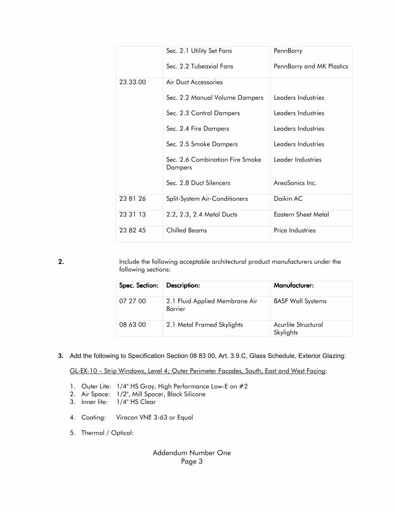
D. Refer to the electrical drawings (E Series) for raceway requirements associated with the Access Control & CCTV systems, including conduit requirements (size and quantity) to each device, and the required termination points for each section of raceway. Certain equipment and cable to support these Owner furnished systems will be provided under Division 26, including low voltage relays to interface ADA door operators with card reader controlled doors, and the installation and line voltage connections to power supplies furnished with the door hardware.”
10.10.10.10. Specification Section 26 32 13 – Emergency Power Generating System: Delete reference to the
“environmental housing” in paragraph 1.3.B regarding submittal information.
11.11.11.11. Specification Section 26 32 13 – Emergency Power Generating System: Delete paragraph 2.3.A, and replace with the following: ““““A. An isosynchronous governor shall maintain frequency regulation not to exceed 3% (1.8 hertz) from no load to full rated load. The governor shall include electronic speed control.”
12.12.12.12. Specification Section 26 32 13 – Emergency Power Generating System: Delete paragraph
2.14.A.3, and replace with the following: ““““3.... Amps interrupting capacity (AIC ratings) shall match ratings shown on the drawings.
13.13.13.13. Specification Section 26 32 13 – Emergency Power Generating System: Revise paragraph 2.10.A,
to delete the reference to remote mounting in paralleling switchgear section, so that it reads: ““““A.... Type A generator mounted Nema 1 vibration isolated steel control panel shall be provided. Panel shall contain but not be limited to the following equipment:” with currently listed items in subparagraphs A. 1 A.10, remaining as is.
14.14.14.14. Specification Section 26 23 00 – Service Switchgear: Add paragraph 2.17 , which shall read as
follows:
“2.17 EMERGENCY SWITCHBOARD ‘XSB”:
A. All sections of the emergency switchboard –designated on the drawings as “XSB”, shall be UL 891 listed and labeled, and shall consist of group mounted, molded case or insulated case circuit breakers in switchboard style construction. All sections shall be front accessible only, and all sections shall be front connected. All circuit breakers shall include electronic trip mechanisms, with adjustable LSI bands.
B. Separate vertical sections shall be provided to house the multiple, individual branches of emergency power including the “emergency branch” feeder circuit breaker, the “optional emergency branch” feeder circuit breaker, and the legally required standby emergency branch” feeder circuit breaker.
C. The switchboard shall be equipped with a PLC based control system to automatically and continuously monitor its load bus and the condition of each fire pump ATS, and upon receiving a signal from either Fire Pump controller that its respective fire pump is running – when on emergency generator power— shall immediately electrically open the feeder circuit breaker serving the “optional emergency loads”, through ATS OP when the load

Addendum Number One
Page 7
on its bus is at, or greater than an initially programmed load of: 290KVA. Automatic re closing of the Optional Branch CB shall be performed when all “fire pump running” signals have reset.”
15.15.15.15. Specification Section 26 23 00 – Service Switchgear: Delete paragraph 2.8 , and replace with the
following: “A. Protective Relays shall be solid state or microprocessor based, high reliability, utility grade
devices mounted in drawout cases in the front switchgear panel. 1. One Reverse Power Relay” 16.16.16.16. Specification Section 26 23 00 – Service Switchgear: Delete requirement for synchroscope from
paragraph 2.5.A.7 , and renumber the remaining items in the list: 7 10, respectively.
DRAWINGSDRAWINGSDRAWINGSDRAWINGS Item No.Item No.Item No.Item No. DescriptionDescriptionDescriptionDescription
1.1.1.1. Plan Sheet A5101: Refer to attached sketch A SK 001. Dimension of accessible toilet made 5’6”.
2.2.2.2. Plan Sheets A1110, A1110A, A1110B, A1110C, A1110D, A1110F: Refer to attached sketch A SK 002. Dimensional clearance clarification.
3.3.3.3. Plan Sheet A0302: Refer to attached sketch A SK 003. Accessible site parking
dimension clarifications.
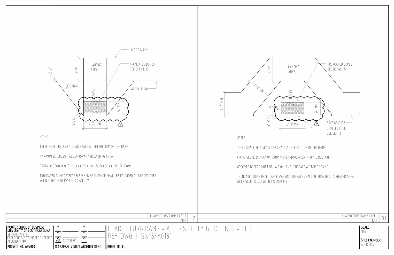
4.4.4.4. Detail Sheet A0131: Refer to attached sketch A SK 004. Revised location of truncated domes on site paving.
5.5.5.5. Plan Sheet A5112 & A5121: Refer to attached sketch A SK 005. Accessible site
parking dimension clarifications.
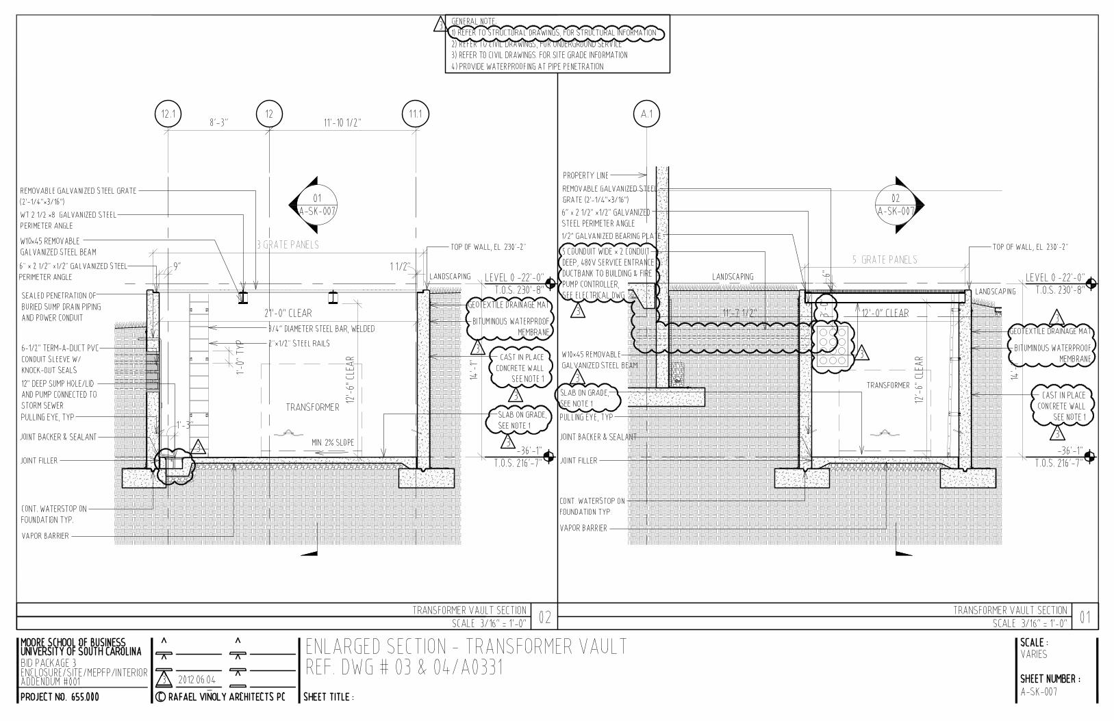
6.6.6.6. Detail Sheet A0331: Refer to attached sketch A SK 006 and A SK 007. Revisions to subgrade electrical transformer vault construction.
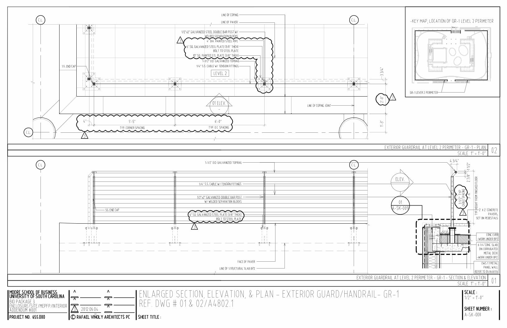
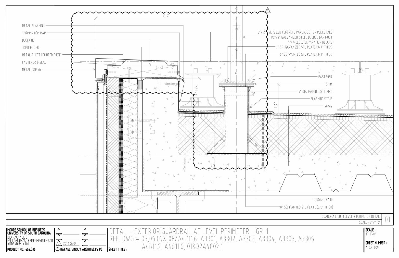
7.7.7.7. Detail Sheet A4802.1, A3301, A3302, A3303, A3304, A3305, A3306, A4611.6:
Refer to attached sketch A SK 008 and A SK 009. Revised guardrail type 1 (GR 1) post connection to deck instead of parapet. Revised post spacing. Revised horizontal cable spacing.
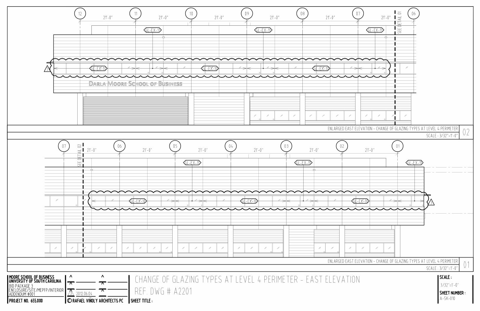
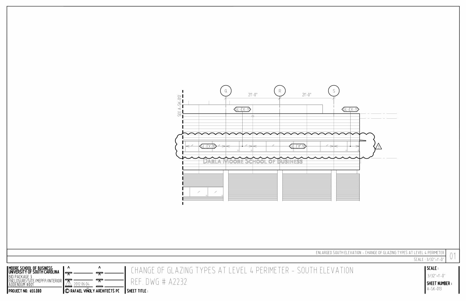
8.8.8.8. Elevations Sheet A2201, A2221, A2222, A2231, A2232, A2202, A3304, A3305,
A3306 and Glazing Schedule A4602: Refer to attached sketch A SK 010, A SK 011, A SK 012, A SK 013, and A SK 014. Revisions to exterior glazing type at Level 4.
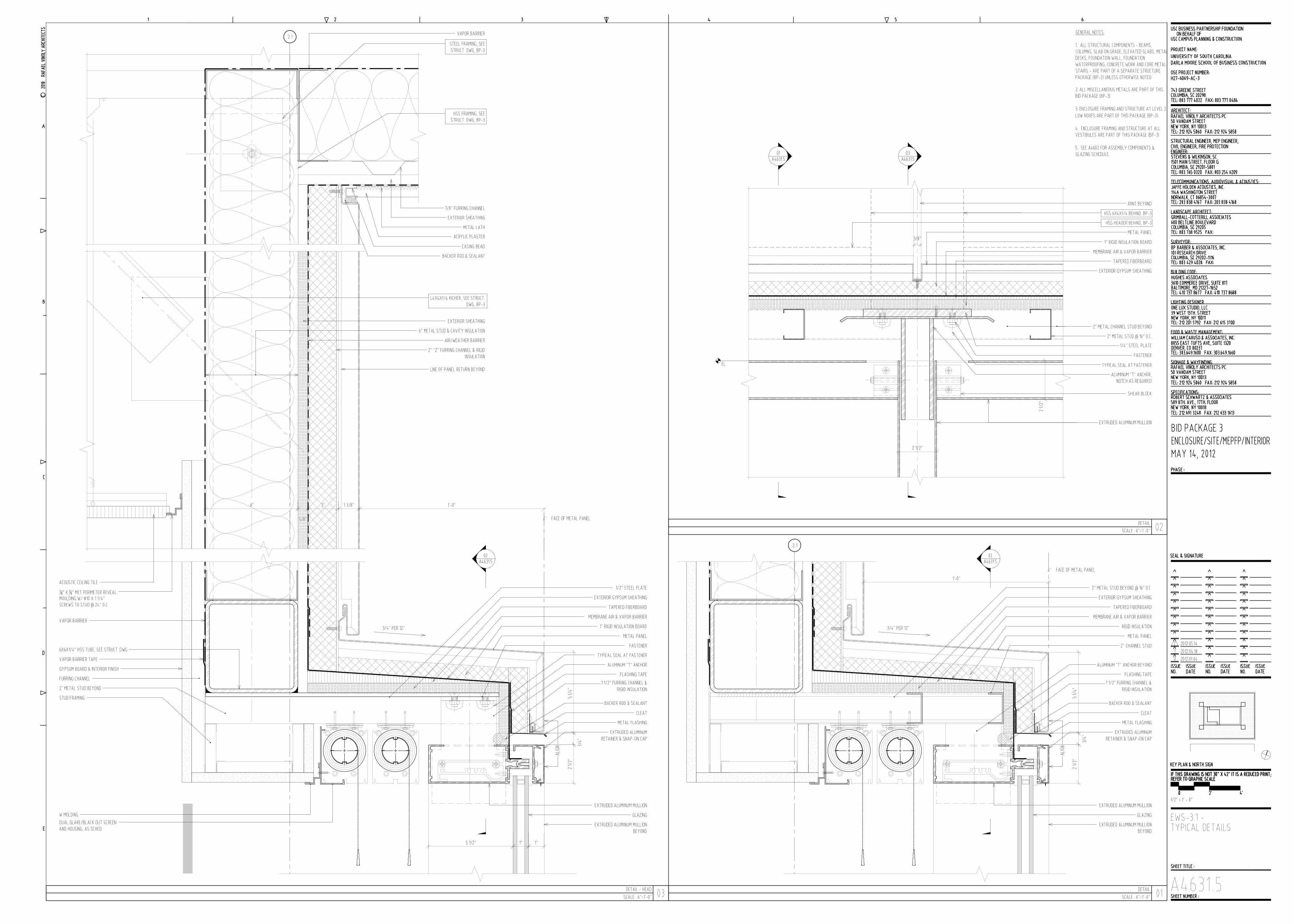
9.9.9.9. Detail Sheet A4631.5. Full sheet (30”x42”) is included to replace one copy of
A4631.4, which was inadvertently printed twice.

Addendum Number One
Page 8
10.10.10.10. Plan Sheet C1500_bp3: Refer to attached sketch C SK 001 Revise location of
electrical vault sump discharge piping.
11.11.11.11. Plan Sheet M9150C & M9150D, revised scale from 1/16”= 1’0” to ¼”=1’0”.
12.12.12.12. Plan Sheet P9250C & P9250D, add the following: “NOTE: ALL PLUMBING VENTS SHALL BE LOCATED 20’ FROM ANY STAIR OR SHAFT PRESSURIZATION FAN INTAKE AND 15’ FROM ANY OTHER AIR INTAKE.”
13.13.13.13. Plan Sheet M0101, add Mechanical Note #41 stating: “For Horizontal Shaft
Enclosures, refer to Reflected Ceiling Plans and Details (A1200 series, A4293/4, A7903.1)”
14.14.14.14. Plan Sheets M1101B, M1101C & M1101D, the fire dampers shown shall be
combination Fire3Smoke Dampers as indicated on M1100B, M1100C & M1100D.
15.15.15.15. Plan Sheet FP0101, delete the Seismic & Wind Requirement Table and delete the text of Note #23 and replace with the following: “As this is a Seismic Design Category C, the system shall be designed & installed in accordance with NFPA 13 which is deemed to meet the requirements of ASCE 7 05 13.6.8.2.”
16.16.16.16. Plan Sheet FP0101, revise Note #7 to state: The fire protection contractor shall
coordinate the location and quantity of all tamper and water flow switches with the fire alarm contractor. The fire protection contractor is responsible for providing the flow and tamper devices and the fire alarm contractor shall provide termination of all wiring.
17.17.17.17. Sheet E0102 Power Riser Diagram: Revise the leader note for SCE&G primary service conduits from the vault to read as follows:
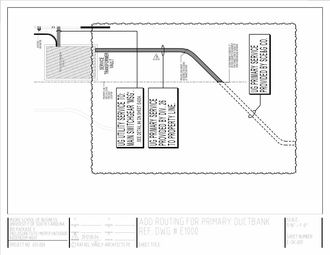
“SIX, 6”C (CONCRETE ENCASED PVC TYPE EB) TO PROPERTY LINE FOR SCE&G PROVIDED MEDIUM VOLTAGE SERVICE CABLES. SEE E1000 FOR ROUTING. INSTALL WITH TOP OF SIX WAY DUCTBANK @ 42” (MINIMUM) BFG.”
*�The Primary service ductbank has been revised from two�6” conduits, to six�6” conduits. The primary ductbank will be similar in section to the one shown in Detail #04 on sheet E4004, except that the primary conduits will be arranged as a 2x3 (or two�wide x three deep) ductbank, in lieu of the 4x2 ductbank shown in the referenced detail.
18.18.18.18. Sheet E1000 Electrical Site & Subgrade Plan: Revise drawing to reflect information contained in the attached Sketch E SK 001, which illustrates the proposed primary electrical ductbank routing from the electrical vault to the property line for tie ins to the local electric utility company’s network.
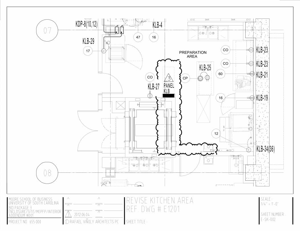
19.19.19.19. Sheet E1201 Kitchen Power Plan Level 0: Revise drawing to reflect information contained in the attached Sketch E SK 002, which illustrates the relocation of Panel KLB.

Addendum Number One
Page 9
20.20.20.20. Sheet E1201 Kitchen Power Plan Level 0: Revise drawing to reflect information contained in the attached Sketch E SK 003, which illustrates the relocation of safety switches serving items in the dishwashing area, and the addition of convenience receptacles in the kitchen office.
21.21.21.21. Sheet E3000 Panelboard Schedules Level 0: Revise drawing to reflect information contained in the attached Sketch E SK 004, which illustrates the addition of a branch circuit to feed the kitchen office receptacles.
22.22.22.22. Sheet E0105 Electrical Energy Monitoring System & TVSS Diagram: Revise drawing to reflect Modbus connections to the electrical meters on the Main Utility CB, and the Distributed Resource (DR) CB. Label Connection to Main Utility CB using Meter Keynote “15”. Label Connection to DR CB using Meter Keynote “16”.
23.23.23.23. Sheet E0105 Electrical Energy Monitoring System & TVSS Diagram: Add Keynotes 15 & 16 to the Power Metering Schedule to read as follows:
“15. Main Utility CB for metering Total Building Loads;
16. Main DR CB for metering future Photovoltaic system supply load”
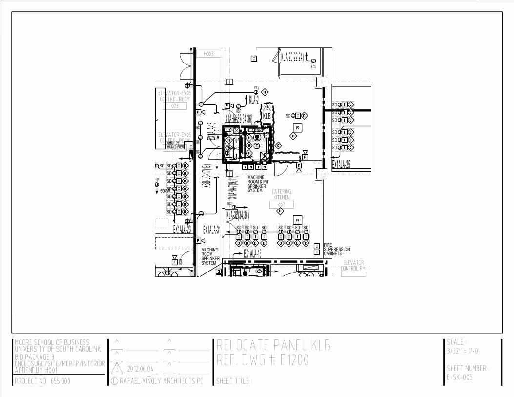
24.24.24.24. Sheet E1200 Power & Signal Plan Level 0: Revise drawing to reflect information contained in the attached Sketch E SK 005, which illustrates the relocation of Panel KLB.
D.D.D.D. BIDDERS RFI’S:BIDDERS RFI’S:BIDDERS RFI’S:BIDDERS RFI’S:
1.1.1.1. Is the Data/Communication portion of this project being Bid separately? I did not see any specifications for it. If so is there a pre qualification form for the Data portion?
Response: For the infrastructure requirements for Low Voltage systems, refer to Telecommunications and Audio Visual Drawings. Also see the Electrical drawings and specifications (including, but not limited to 267000 Empty Raceway Systems). Division 27 Communications specifications are not included in Bid Package 3. Audio Visual and Telecommunications cabling and equipment are not part of Bid Package 3. Only the infrastructure for it is. Infrastructure (defined as conduits, backboxes, j hooks, etc) for AV and IT is to be installed by the Bid Package 3 Div 26 (electrical) contractor.
END OF ADDENDUMEND OF ADDENDUMEND OF ADDENDUMEND OF ADDENDUM

1
MINUTES OF MEETING
Project: DARLA MOORE SCHOOL OF BUSINESS
BP- 3: ENCLOSURE/SITE/MEPFP/INTERIOR STRUCTURE State Project Number H27-6069-AC-3 Subject: PRE-BID MEETING Date: May 31, 2012 at 2:00 PM EST Location: University of South Carolina – Campus Planning and Construction Attendees: See attached Sign-in Sheet A Non-Mandatory Pre-bid Meeting was conducted at the University of South Carolina office of Campus Planning and Construction at 743 Greene Street in Columbia, SC on May 31, 2012 at 2:00 PM. The attached Agenda was followed and additional discussion was noted as follows: 1. The scope and nature of the project was described and its importance to the
University was discussed. It was noted that the work of this bid package would be the fourth bid package associated with the multi-phase construction of a new School of Business for the University of South Carolina. The first phase (BP-1A Electrical Relocation) has been completed. The initial portion of work for the second phase (BP-1C Civil) has been completed and this contractor will return near the end of the project for remaining civil work in their scope. The third phase (BP-2 Structure) is currently underway.
2. The Design Team presented a brief slide presentation to provide an overview of the
entire project and key components associated with each of the work packages. Special design features and elements of the BP-3 base bid and three included alternates were reviewed.
3. The University’s desire to encourage participation of small, local and minority
business enterprises was discussed at length. Bidders were strongly encouraged to seek participation through subcontracting and partnering. Ms. Helen Zeigler, Associate Vice President for Business Affairs for the University spoke on behalf of President Harris Pastides on this matter. Ms. Zeigler stressed that participation in this critical Outreach Initiative was a vital business driver for the City, the State and the

2
University. Ms. Zeigler asked that all parties do their best to seek participation and to document their efforts towards this end. Mr. Anthony Lawrence also spoke on this matter and indicated that Brownstone Construction Group was a resource available to all parties to assist in these efforts. Brownstone will be sponsoring a Participation Fair at the existing Business School at 1705 College Street at 6:00 PM on June 14th. Formal announcements will be distributed to all in attendance at the Pre-Bid, all plan-holders, and others. General Contractors and vendors were encouraged to participate and invited to set up booths or displays. Anthony and his staff can be contacted for assistance at Brownstone Construction Group, 1213 Lady Street, Suite 214, Columbia, SC 29201. Office: (803) 376-6044 | Fax: (803) 376-6099 [email protected] www.bstonegroup.com
4. The date and location for the bid opening were reviewed. Bidders were cautioned to
arrive early and take care of visitor sign in and parking passes prior to the time of the bid opening. The official time was noted as the time indicated on the wall clock in the conference room. Any late bids will be rejected as non-responsive. Bidders were cautioned to ensure that persons delivering bids were familiar with the location and time requirements. Bidders should confirm receipt of any bids delivered by FedEx or delivery services.
5. The Supplementary Instructions to Bidders (AIA A701) and O201-OSE
Supplementary Instructions to Bidders were reviewed. Bidder’s attention was brought to paragraph 9.7 for requirements of the contractor to provider Builder’s Risk insurance. Attention was brought to paragraph 9.9 of the 0201-OSE as to the involvement in the project of the Construction Manager.
6. Bidding requirements and the Bid Form were reviewed including provisions for
alternates and subcontractor listings.
7. Licensing requirements were reviewed. Bidders must be properly licensed as General Contractor - Building to bid as a prime bidder per State Law.
8. Any requests for substitutions must be received by end of the day Monday June 18th
at the latest. At least one addendum will be issued. The last addenda will be issued no later than June 22nd at 2:00 PM. All questions must be submitted in writing prior to this time.
9. Supplementary Conditions, including the University of South Carolina
Supplementary Conditions, were reviewed. Attention was called to information concerning the contractor’s lay-down area and related parking requirements. It was noted that contractors for other bid packages will also be on sight during portions of the work of this bid package and these contractors will share in the use of the lay-down area.
10. The scope and phasing of the project work and timing of the other bid packages were
reviewed in general terms. Bidders were referred to section 01 10 00 Summary for
3
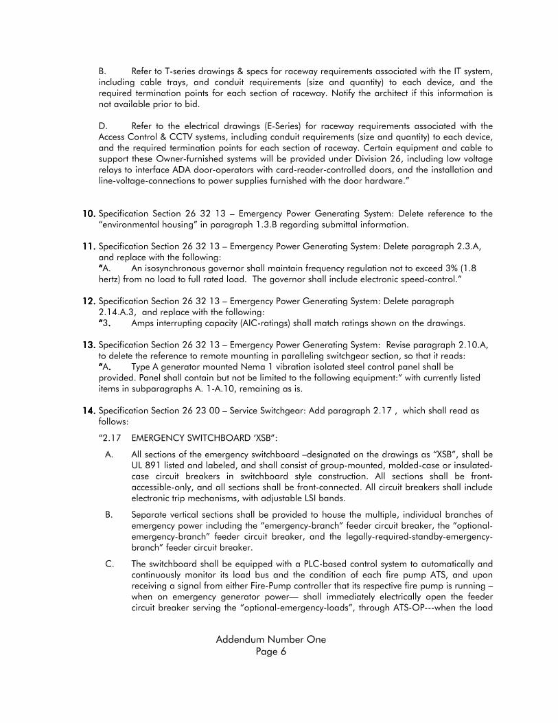
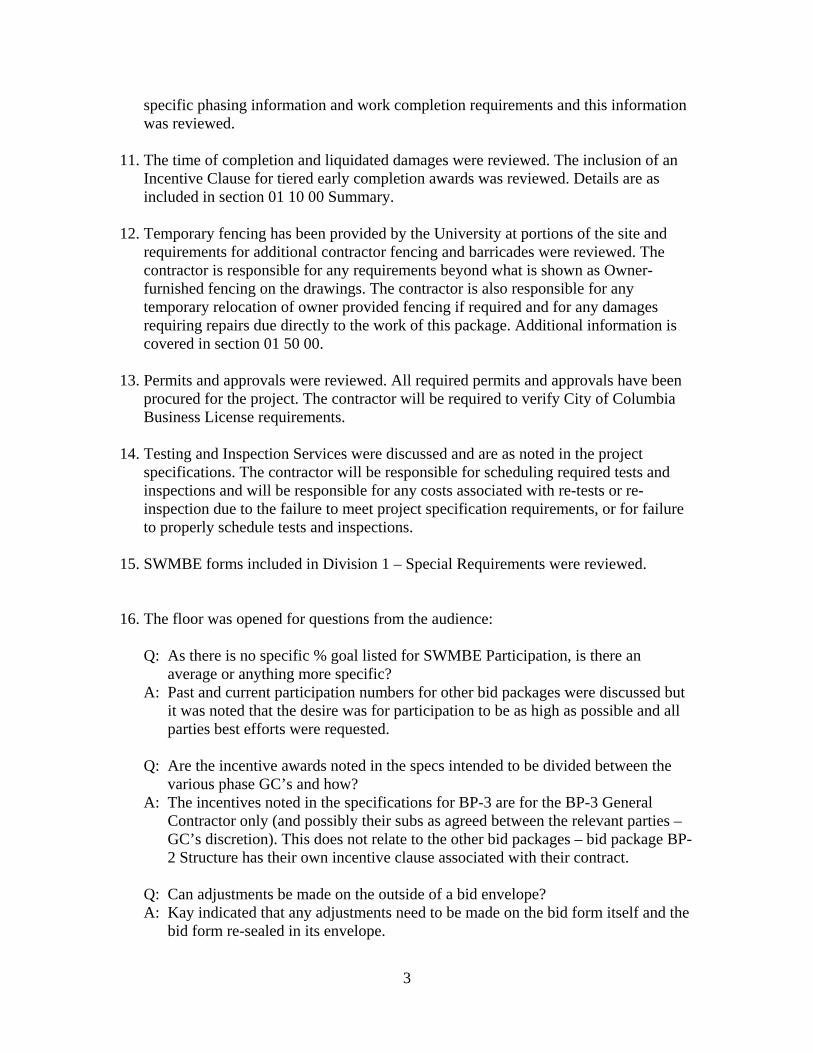
specific phasing information and work completion requirements and this information was reviewed.
11. The time of completion and liquidated damages were reviewed. The inclusion of an
Incentive Clause for tiered early completion awards was reviewed. Details are as included in section 01 10 00 Summary.
12. Temporary fencing has been provided by the University at portions of the site and
requirements for additional contractor fencing and barricades were reviewed. The contractor is responsible for any requirements beyond what is shown as Owner-furnished fencing on the drawings. The contractor is also responsible for any temporary relocation of owner provided fencing if required and for any damages requiring repairs due directly to the work of this package. Additional information is covered in section 01 50 00.
13. Permits and approvals were reviewed. All required permits and approvals have been
procured for the project. The contractor will be required to verify City of Columbia Business License requirements.
14. Testing and Inspection Services were discussed and are as noted in the project
specifications. The contractor will be responsible for scheduling required tests and inspections and will be responsible for any costs associated with re-tests or re-inspection due to the failure to meet project specification requirements, or for failure to properly schedule tests and inspections.
15. SWMBE forms included in Division 1 – Special Requirements were reviewed.
16. The floor was opened for questions from the audience:
Q: As there is no specific % goal listed for SWMBE Participation, is there an average or anything more specific?
A: Past and current participation numbers for other bid packages were discussed but it was noted that the desire was for participation to be as high as possible and all parties best efforts were requested.
Q: Are the incentive awards noted in the specs intended to be divided between the
various phase GC’s and how? A: The incentives noted in the specifications for BP-3 are for the BP-3 General
Contractor only (and possibly their subs as agreed between the relevant parties – GC’s discretion). This does not relate to the other bid packages – bid package BP-2 Structure has their own incentive clause associated with their contract.
Q: Can adjustments be made on the outside of a bid envelope? A: Kay indicated that any adjustments need to be made on the bid form itself and the
bid form re-sealed in its envelope.

4
Q: Will local contractors have an advantage in the awards process? A: No, this is a straight bid following the State’s standard procurement guidelines.
END OF MINUTES

PRE-BID CONFERENCE UNIVERSITY OF SOUTH CAROLINA – DARLA MOORE SCHOOL OF BUSINESS
BP-3: ENCLOSURE/SITE/MEPFP/INTERIOR – STATE PROJECT NO. H27-6069-AC-3 MAY 31, 2012 @ 2:00 PM
AGENDA
I. Introductions II. Project Description and Scope III. Bid Date and Location
University of South Carolina - Campus Planning and Construction 743 Greene Street Columbia, South Carolina 29208
Thursday, June 28, 2012 Bids Due: 2:00 P.M. EST
IV. Bidding Requirements
1 Instructions to Bidders – AIA A701 – 1997 Edition 2 Standard Supplementary Instructions to Bidders – OSE 00201 3 Bid Security – 5% of the Base Bid 4 Bidders must be properly licensed for this project 5 Bids must be received by the time indicated. Late bids will be rejected 6 Bids may not be qualified 7 Bid Form – Completed SE-330. Enclosed in a sealed, opaque envelope, bearing name,
address of the bidder, and name and number of project. 6 Acknowledge Receipt of addenda 7 Time of Completion and Liquidated Damages 7 All bids must be signed and must comply with the laws of South Carolina
V. Substitution Requests- 10 days prior (Monday, June 18, 2012) VI. Addenda – Last addenda to be issued no later than 2:00 PM, Friday, June 22, 2012
VII. Review of Plans and Specifications
1 Owner and Contractor Agreement – AIA A201, 2007 Edition 2 Standard Modifications – OSE 00501 3 Standard Supplementary Conditions – OSE 00811 4 USC Supplemental Conditions 5 Summary of Work 6 Permits & Rights of Way 7 Testing & Inspection Services 8 LEED Initiatives
VIII. SWMBE Overview
IX. Questions and Answers


GLAZING SCHEDULE
GL-EX-01 STRIP WINDOWS AND WINDOW WALLS OUTER LITE: 1/4" HEAT STRENGTHENED CLEAR, HIGH PERFORMANCE LOW-E ON #2 VIRACON VUE 1-50 OR EQUAL


Darla Moore School of Business Construction State Project No. H27-6069-AC-3
UNIVERSITY OF SOUTH CAROLINA ELECTRIC-DRIVE, CENTRIFUGAL FIRE PUMPS ISSUE 3 2012.06.04 21 31 13 - 1
SECTION 21 31 13 - ELECTRIC-DRIVE, CENTRIFUGAL FIRE PUMPS
PART 1 - GENERAL
1.1 RELATED DOCUMENTS
A. Drawings and general provisions of the Contract, including General and Supplementary Conditions and Division 01 Specification Sections, apply to this Section.
1.2 SUMMARY
A. Section Includes:
1. Split-case fire pumps. 2. Fire-pump accessories and specialties. 3. Flowmeter systems.
1.3 PERFORMANCE REQUIREMENTS
A. Seismic Performance: Fire pumps shall withstand the effects of earthquake motions determined according to ASCE/SEI 7.
1. The term "withstand" means "the unit will remain in place without separation of any parts from the device when subjected to the seismic forces specified and the unit will be fully operational after the seismic event."
B. Pump Equipment, Accessory, and Specialty Pressure Rating: 175 psig (1200 kPa) minimum unless higher pressure rating is indicated.
1.4 ACTION SUBMITTALS
A. Product Data: For each type of product indicated. Include rated capacities, operating characteristics, performance curves, electrical characteristics, and furnished specialties and accessories.
B. Shop Drawings: For fire pumps, motor drivers, and fire-pump accessories and specialties. Include plans, elevations, sections, details, and attachments to other work.
1. Detail equipment assemblies and indicate dimensions, weights, loads, required clearances, method of field assembly, components, and location and size of each field connection.
2. Wiring Diagrams: For power, signal, and control wiring.
1.5 INFORMATIONAL SUBMITTALS
A. Seismic Qualification Certificates: For fire pumps, accessories, and components, from manufacturer.

Darla Moore School of Business Construction State Project No. H27-6069-AC-3
UNIVERSITY OF SOUTH CAROLINA ELECTRIC-DRIVE, CENTRIFUGAL FIRE PUMPS ISSUE 3 2012.06.04 21 31 13 - 2
1. Basis for Certification: Indicate whether withstand certification is based on actual test of assembled components or on calculation.
2. Dimensioned Outline Drawings of Equipment Unit: Identify center of gravity and locate and describe mounting and anchorage provisions.
3. Detailed description of equipment anchorage devices on which the certification is based and their installation requirements.
B. Product Certificates: For each fire pump, from manufacturer.
C. Source quality-control reports.
D. Field quality-control reports.
1.6 CLOSEOUT SUBMITTALS
A. Operation and Maintenance Data: For fire pumps to include in operation and maintenance manuals.
1.7 QUALITY ASSURANCE
A. Electrical Components, Devices, and Accessories: Listed and labeled as defined in NFPA 70, by a qualified testing agency, and marked for intended location and application.
B. NFPA Compliance: Comply with NFPA 20, "Installation of Stationary Pumps for Fire Protection."
1.8 COORDINATION
A. Coordinate sizes and locations of concrete bases with actual equipment provided.
PART 2 - PRODUCTS
2.1 GENERAL REQUIREMENTS FOR CENTRIFUGAL FIRE PUMPS
A. Description: Factory-assembled and -tested fire-pump and driver unit.
B. Base: Fabricated and attached to fire-pump and driver unit with reinforcement to resist movement of pump during seismic events when base is anchored to building substrate.
C. Finish: Red paint applied to factory-assembled and -tested unit before shipping.
2.2 HORIZONTALLY MOUNTED, SINGLE-STAGE, SPLIT-CASE FIRE PUMPS
A. Manufacturers: Subject to compliance with requirements, available manufacturers offering products that may be incorporated into the Work include, but are not limited to, the following:
1. A-C Fire Pump Systems; a business of ITT Industries. 2. Patterson Pump Company; a subsidiary of the Gorman-Rupp Company. 3. Peerless Pump, Inc.

Darla Moore School of Business Construction State Project No. H27-6069-AC-3
UNIVERSITY OF SOUTH CAROLINA ELECTRIC-DRIVE, CENTRIFUGAL FIRE PUMPS ISSUE 3 2012.06.04 21 31 13 - 3
4. S.A. Armstrong Limited. 5. Equal
B. Pump:
1. Standard: UL 448, for split-case pumps for fire service. 2. Casing: Axially split case, cast iron with ASME B16.1 pipe-flange connections. 3. Impeller: Cast bronze, statically and dynamically balanced, and keyed to shaft. 4. Wear Rings: Replaceable bronze. 5. Shaft and Sleeve: Steel shaft with bronze sleeve.
a. Shaft Bearings: Grease-lubricated ball bearings in cast-iron housing. b. Seals: Stuffing box with minimum of four rings of graphite-impregnated braided
yarn and bronze packing gland.
6. Mounting: Pump and driver shafts are horizontal, with pump and driver on same base.
C. Coupling: Flexible and capable of absorbing torsional vibration and shaft misalignment. Include metal coupling guard.
D. Driver:
1. Standard: UL 1004A. 2. Type: Electric motor; NEMA MG 1, polyphase Design B.
2.3 FIRE-PUMP ACCESSORIES AND SPECIALTIES
A. Automatic Air-Release Valves: Comply with NFPA 20 for installation in fire-pump casing.
B. Circulation Relief Valves: UL 1478, brass, spring loaded; for installation in pump discharge piping.
C. Relief Valves:
1. Manufacturers: Subject to compliance with requirements, provide products by one of the following or equal:
a. BERMAD Control Valves. b. CLA-VAL Automatic Control Valves. c. Kunkle Valve; a part of Tyco International Ltd. d. OCV Control Valves. e. Watts Regulator Company; a division of Watts Water Technologies, Inc. f. Zurn Plumbing Products Group; Wilkins Water Control Products.
2. Description: UL 1478, bronze or cast iron, spring loaded; for installation in fire-suppression water-supply piping.
D. Inlet Fitting: Eccentric tapered reducer at pump suction inlet.
E. Outlet Fitting: Concentric tapered reducer at pump discharge outlet.
F. Discharge Cone: Closed or open type.

Darla Moore School of Business Construction State Project No. H27-6069-AC-3
UNIVERSITY OF SOUTH CAROLINA ELECTRIC-DRIVE, CENTRIFUGAL FIRE PUMPS ISSUE 3 2012.06.04 21 31 13 - 4
G. Hose Valve Manifold Assembly:
1. Standard: Comply with requirements in NFPA 20. 2. Header Pipe: ASTM A 53/A 53M, Schedule 40, galvanized steel with ends threaded
according to ASME B1.20.1. 3. Header Pipe Fittings: ASME B16.4, galvanized cast-iron threaded fittings. 4. Automatic Drain Valve: UL 1726. 5. Manifold:
a. Test Connections: Comply with UL 405 except provide outlets without clappers instead of inlets.
b. Body: Flush type, brass or ductile iron, with number of outlets required by NFPA 20. c. Nipples: ASTM A 53/A 53M, Schedule 40, galvanized-steel pipe with ends
threaded according to ASME B1.20.1. d. Adapters and Caps with Chain: Brass or bronze, with outlet threaded according to
NFPA 1963 and matching local fire-department threads. e. Escutcheon Plate: Brass or bronze; rectangular. f. Hose Valves: UL 668, bronze, with outlet threaded according to NFPA 1963 and
matching local fire-department threads. g. Exposed Parts Finish: [Polished] [Rough] [brass] [, chrome plated]. h. Escutcheon Plate Marking: Equivalent to "FIRE PUMP TEST."
6. Manifold:
a. Test Connections: Comply with UL 405 except provide outlets without clappers instead of inlets.
b. Body: Exposed type, brass, with number of outlets required by NFPA 20. c. Escutcheon Plate: Brass or bronze; round. d. Hose Valves: UL 668, bronze, with outlet threaded according to NFPA 1963 and
matching local fire-department threads. Include caps and chains. e. Exposed Parts Finish: Rough, chrome plated. f. Escutcheon Plate Marking: Equivalent to "FIRE PUMP TEST."
2.4 FLOWMETER SYSTEMS
A. Manufacturers: Subject to compliance with requirements, provide products by one of the following or equal:
1. Fire Research Corp. 2. Reddy-Buffaloes Pump Company 3. Equal
B. Description: UL-listed, fire-pump flowmeter system with capability to indicate flow to not less than 175 percent of fire-pump rated capacity.
C. Pressure Rating: 175 psig (1200 kPa) minimum.
D. Sensor: Annubar probe, orifice plate, or venturi unless otherwise indicated. Sensor size shall match pipe, tubing, flowmeter, and fittings.
E. Permanently Mounted Flowmeter: Compatible with flow sensor; with dial not less than 4-1/2 inches (115 mm) in diameter. Include bracket or device for wall mounting.

Darla Moore School of Business Construction State Project No. H27-6069-AC-3
UNIVERSITY OF SOUTH CAROLINA ELECTRIC-DRIVE, CENTRIFUGAL FIRE PUMPS ISSUE 3 2012.06.04 21 31 13 - 5
1. Tubing Package: NPS 1/8 or NPS 1/4 (DN 6 or DN 10) soft copper tubing with copper or brass fittings and valves.
F. Portable Flowmeter: Compatible with flow sensor; with dial not less than 4-1/2 inches (115 mm) in diameter and with two 12-foot- (3.7-m-) long hoses in carrying case.
2.5 GROUT
A. Standard: ASTM C 1107, Grade B, post-hardening and volume-adjusting, dry, hydraulic-cement grout.
B. Characteristics: Nonshrink and recommended for interior and exterior applications.
C. Design Mix: 5000-psi (34-MPa), 28-day compressive strength.
D. Packaging: Premixed and factory packaged.
2.6 SOURCE QUALITY CONTROL
A. Testing: Test and inspect fire pumps according to UL 448 requirements for "Operation Test" and "Manufacturing and Production Tests."
1. Verification of Performance: Rate fire pumps according to UL 448.
B. Fire pumps will be considered defective if they do not pass tests and inspections.
C. Prepare test and inspection reports.
PART 3 - EXECUTION
3.1 EXAMINATION
A. Examine equipment bases and anchorage provisions, with Installer present, for compliance with requirements and for conditions affecting performance of fire pumps.
B. Examine roughing-in for fire-suppression piping systems to verify actual locations of piping connections before fire-pump installation.
C. Proceed with installation only after unsatisfactory conditions have been corrected.
3.2 INSTALLATION
A. Fire-Pump Installation Standard: Comply with NFPA 20 for installation of fire pumps, relief valves, and related components.
B. Equipment Mounting: Install fire pumps on concrete bases. Comply with requirements for concrete bases specified in Division 03.

Darla Moore School of Business Construction State Project No. H27-6069-AC-3
UNIVERSITY OF SOUTH CAROLINA ELECTRIC-DRIVE, CENTRIFUGAL FIRE PUMPS ISSUE 3 2012.06.04 21 31 13 - 6
1. Install dowel rods to connect concrete base to concrete floor. Unless otherwise indicated, install dowel rods on 18-inch (450-mm) centers around the full perimeter of concrete base.
2. For supported equipment, install epoxy-coated anchor bolts that extend through concrete base and anchor into structural concrete floor.
3. Place and secure anchorage devices. Use setting drawings, templates, diagrams, instructions, and directions furnished with items to be embedded.
4. Install anchor bolts to elevations required for proper attachment to supported equipment.
C. Install fire-pump suction and discharge piping equal to or larger than sizes required by NFPA 20.
D. Support piping and pumps separately so weight of piping does not rest on pumps.
E. Install valves that are same size as connecting piping. Comply with requirements for fire-protection valves specified in Section 211200 "Fire-Suppression Standpipes" and Section 211313 "Wet-Pipe Sprinkler Systems."
F. Install pressure gages on fire-pump suction and discharge flange pressure-gage tappings. Comply with requirements for pressure gages specified in Section 211200 "Fire-Suppression Standpipes" and Section 211313 "Wet-Pipe Sprinkler Systems."
G. Install piping hangers and supports, anchors, valves, gages, and equipment supports according to NFPA 20.
H. Install flowmeters and sensors. Install flowmeter-system components and make connections according to NFPA 20 and manufacturer's written instructions.
I. Electrical Wiring: Install electrical devices furnished by equipment manufacturers but not factory mounted. Furnish copies of manufacturers' wiring diagram submittals to electrical Installer.
J. Wiring Method: Conceal conductors and cables in accessible ceilings, walls, and floors where possible.
3.3 ALIGNMENT
A. Align split-case pump and driver shafts after complete unit has been leveled on concrete base, grout has set, and anchor bolts have been tightened.
B. After alignment is correct, tighten anchor bolts evenly. Fill baseplate completely with grout, with metal blocks and shims or wedges in place. Tighten anchor bolts after grout has hardened. Check alignment and make required corrections.
C. Align piping connections.
D. Align pump and driver shafts for angular and parallel alignment according to HI 1.4 and to tolerances specified by manufacturer.
3.4 CONNECTIONS
A. Comply with requirements for piping and valves specified in Section 211200 "Fire-Suppression Standpipes" and Section 211313 "Wet-Pipe Sprinkler Systems."

Darla Moore School of Business Construction State Project No. H27-6069-AC-3
UNIVERSITY OF SOUTH CAROLINA ELECTRIC-DRIVE, CENTRIFUGAL FIRE PUMPS ISSUE 3 2012.06.04 21 31 13 - 7
B. Drawings indicate general arrangement of piping, fittings, and specialties.
C. Install piping adjacent to pumps and equipment to allow service and maintenance.
D. Connect relief-valve discharge to drainage piping or point of discharge.
E. Connect flowmeter-system meters, sensors, and valves to tubing.
F. Connect fire pumps to their controllers.
3.5 IDENTIFICATION
A. Identify system components. Comply with requirements for fire-pump marking according to NFPA 20.
3.6 FIELD QUALITY CONTROL
A. Test each fire pump with its controller as a unit. Comply with requirements for electric-motor-driver fire-pump controllers specified in Section 213900 "Controllers for Fire-Pump Drivers."
B. Manufacturer's Field Service: Engage a factory-authorized service representative to inspect, test, and adjust components, assemblies, and equipment installations, including connections.
C. Perform tests and inspections.
1. Manufacturer's Field Service: Engage a factory-authorized service representative to inspect components, assemblies, and equipment installations, including connections, and to assist in testing.
D. Tests and Inspections:
1. After installing components, assemblies, and equipment including controller, test for compliance with requirements.
2. Test according to NFPA 20 for acceptance and performance testing. 3. Leak Test: After installation, charge system and test for leaks. Repair leaks and retest until
no leaks exist. 4. Operational Test: After electrical circuitry has been energized, start units to confirm proper
motor rotation and unit operation. 5. Test and adjust controls and safeties. Replace damaged and malfunctioning controls and
equipment.
E. Components, assemblies, and equipment will be considered defective if they do not pass tests and inspections.
F. Prepare test and inspection reports.
G. Furnish fire hoses in number, size, and length required to reach storm drain or other acceptable location to dispose of fire-pump test water. Hoses are for tests only and do not convey to Owner.

Darla Moore School of Business Construction State Project No. H27-6069-AC-3
UNIVERSITY OF SOUTH CAROLINA ELECTRIC-DRIVE, CENTRIFUGAL FIRE PUMPS ISSUE 3 2012.06.04 21 31 13 - 8
3.7 STARTUP SERVICE
A. Engage a factory-authorized service representative to perfor] startup service.
1. Complete installation and startup checks according to manufacturer's written instructions.
3.8 DEMONSTRATION
A. Engage a factory-authorized service representative to train Owner's maintenance personnel to adjust, operate, and maintain fire pumps.
END OF SECTION 21 31 13
Darla Moore School of Business Construction State Project No. H27-6069-AC-3
UNIVERSITY OF SOUTH CAROLINA DEDICATED OUTDOOR-AIR UNITS ISSUE 3 2012.06.04 23 74 33 - 1
SECTION 23 74 33 - DEDICATED OUTDOOR-AIR UNITS
PART 1 - GENERAL
1.1 RELATED DOCUMENTS
A. Drawings and general provisions of the Contract, including General and Supplementary Conditions and Division 01 Specification Sections, apply to this Section.
1.2 SUMMARY
A. Section includes factory-packaged units capable of supplying up to 100 percent outdoor air and providing cooling and heating.
1.3 ACTION SUBMITTALS
A. Product Data: For each type of product. Include rated capacities, operating characteristics, and furnished specialties and accessories.
B. LEED Submittals:
1. Product Data for Prerequisite EA 2: Documentation indicating that units comply with applicable requirements in ASHRAE/IESNA 90.1.
2. Product Data for Prerequisite EA 3: Documentation indicating that refrigerants comply. 3. Product Data for Credit EA 4: Documentation indicating that equipment and refrigerants
comply. 4. Product Data for Prerequisite EQ 1: Documentation indicating that units comply with
ASHRAE 62.1, Section 5 - "Systems and Equipment." 5. Product Data for Credit EQ 1: Documentation indicating that units are equipped with a
direct outdoor airflow-measuring device capable of measuring the minimum outdoor airflow with accuracy within 15 percent of the design minimum airflow rate, as defined by ASHRAE 62.1.
6. Product Data for Credit EQ 4.1: For solvent cements and adhesive primers, documentation including printed statement of VOC content.
7. Product Data for Credit EQ 5: Documentation indicating that units include MERV 13 filters rated according to ASHRAE 52.2.
C. Shop Drawings:
1. Include plans, elevations, sections, and attachment details. 2. Include details of equipment assemblies. Indicate dimensions, weights, loads, required
clearances, method of field assembly, components, and location and size of each field connection.
3. Prepare the following by or under the supervision of a qualified professional engineer:
a. Mounting Details: For securing and flashing roof curb to roof structure. Indicate coordinating requirements with roof membrane system.
b. Include diagrams for power, signal, and control wiring.

Darla Moore School of Business Construction State Project No. H27-6069-AC-3
UNIVERSITY OF SOUTH CAROLINA DEDICATED OUTDOOR-AIR UNITS ISSUE 3 2012.06.04 23 74 33 - 2
D. Delegated-Design Submittal: For design of seismic restraints and wind restraints, including analysis data signed and sealed by the qualified professional engineer responsible for their preparation.
1. Unit fabrication and assembly details. 2. Vibration Isolation Base Details: Detail fabrication including anchorages and attachments
to structure and to supported equipment. Include adjustable motor bases, rails, and frames for equipment mounting.
3. Design Calculations:
a. Calculate requirements for selecting vibration isolators and seismic restraints and wind restraints and for designing vibration isolation bases.
b. Indicate compliance with "Performance Requirements" article.
1.4 INFORMATIONAL SUBMITTALS
A. Coordination Drawings: Roof-curb mounting details, drawn to scale, on which the following items are shown and coordinated with each other, using input from installers of the items involved:
1. Size and location of unit-mounted rails and anchor points and methods for anchoring units to roof curb.
2. Required roof penetrations for ducts, pipes, and electrical raceways, including size and location of each penetration.
B. Seismic Qualification Certificates: For dedicated outdoor-air units, accessories, and components, from manufacturer.
1. Basis for Certification: Indicate whether withstand certification is based on actual test of assembled components or on calculation.
2. Dimensioned Outline Drawings of Equipment Unit: Identify center of gravity and locate and describe mounting and anchorage provisions.
3. Detailed description of equipment anchorage devices on which the certification is based and their installation requirements.
(C & D DELETED)
1.5 CLOSEOUT SUBMITTALS
A. Operation and Maintenance Data: For units to include in emergency, operation, and maintenance manuals.
1.6 QUALITY ASSURANCE
A. Equipment must meet or exceed Energy Star requirements where applicable.
1.7 MAINTENANCE MATERIAL SUBMITTALS
A. Furnish extra materials that match products installed and that are packaged with protective covering for storage and identified with labels describing contents.
Darla Moore School of Business Construction State Project No. H27-6069-AC-3
UNIVERSITY OF SOUTH CAROLINA DEDICATED OUTDOOR-AIR UNITS ISSUE 3 2012.06.04 23 74 33 - 3
1. Fan Belts: One set for each belt-driven fan. 2. Filters: One set for each unit.
1.8 WARRANTY
A. The unit manufacturer shall warrant to the Buyer that for a period of eighteen months from the date of shipment the goods to be delivered to the Buyer shall in all material respects be free from defects in material and workmanship when used in a proper and normal manner. Should any failure to conform to the above appear within eighteen months after the date of shipment, the unit manufacturer shall upon prompt notification thereof during the Warranty Period and confirmation to the unit manufacturer’s satisfaction that the goods have been stored, installed, operated and maintained properly and in accordance with standard industry practice, correct the non-conformity at the unit manufacturer’s option either by repairing any defective part or parts or by making available at the unit manufacturer’s plant a repaired or replacement part.
B. Extended wheel warranty - Energy Recovery Wheels shall carry a full parts and labor warranty for (5) years. Warranty shall cover both thermodynamic performance and mechanical operation of the entire rotating assembly except for belts, motor, and A-C inverter. Energy Recovery Wheel manufacturer shall provide field service engineer for start-up adjustment and calibration of controls, and instruction to operating personnel.
PART 2 - PRODUCTS
2.1 MANUFACTURERS
A. Manufacturers: Subject to compliance with requirements, provide products by one of the following or equal:
1. Addison. 2. Desert Aire. 3. Governair. 4. Munters Corporation, Dehumidification Division; Des Champs Products. 5. SEMCO.
2.2 PERFORMANCE REQUIREMENTS
A. General Fabrication Requirements: Comply with requirements in ASHRAE 62.1, Section 5 - "Systems and Equipment," and Section 7 - "Construction and System Start-up."
B. Delegated Design: Engage a qualified professional engineer, as defined in Division 01 Section "Quality Requirements," to design seismic restraints and wind restraints.
C. Seismic Performance: Units shall withstand the effects of earthquake motions determined according to ASCE/SEI 7.
1. The term "withstand" means "the unit will remain in place without separation of any parts when subjected to the seismic forces specified and the unit will be fully operational after the seismic event."

Darla Moore School of Business Construction State Project No. H27-6069-AC-3
UNIVERSITY OF SOUTH CAROLINA DEDICATED OUTDOOR-AIR UNITS ISSUE 3 2012.06.04 23 74 33 - 4
D. Electrical components, devices, and accessories: Listed and labeled as defined in NFPA 70, by a qualified testing agency, and marked for intended location and application.
E. Capacities and Characteristics – See Schedule Drawings.
(F & G DELETED)
2.3 CASING
A. Wall and roof panels shall be acoustical type and consist of 2 inch thick dual wall 18 gauge galvanized solid exterior skins and 22 gauge galvanized steel solid interior skins enclosing 2 inch thick 3 pcf mineral wool insulation. Post and frame panel system is not acceptable. Center wall and fan wall construction shall be the same as the exterior panel construction with a minimum thickness of 2”. A painted structural steel base shall support the housing, roll formed bases are not acceptable. The base includes a solid welded, water tight, epoxy painted 12-gauge floor with 6" thick mineral wool insulation. The perimeter of the floor shall have a minimum one inch lip. The bottom face of the insulation shall be protected with a 22 gauge galvanized steel cover. Floor openings shall have perimeter lips turned up into unit and be covered by a protective grate. Lifting lugs shall be welded to the structural base. Unit exterior shall be painted with one coat of Sherwin Williams KEM 400 Alkyd Enamel. If a custom color is required, a color sample, or Sherwin Williams color number must be supplied at the time the unit is released to production.
1. Acoustical performance for both airborne noise transmission and radiated noisetransmission shall be as follows:
2" panels Octave Band Frequency (Hz) 125 250 500 1000 2000 4000 Absorption Coefficient 0.58 0.93 1.16 1.18 1.15 1.12 1.10 NRC Transmission Loss (dB) 26 29 33 44 52 60 38 STC
2. Thermal performance of panels shall provide for a U-factor of 0.10 for 2" panels.
B. Panel performance data certified by an industry recognized independent acoustical testing laboratory shall be submitted to the engineer to verify that the completed enclosure will meet or exceed the requirements in this specification. Such data shall have been the result of certified independent testing of a representative sample of the manufacturer's regular product in accordance with applicable provisions of the American Society for Testing and Materials Procedures (423-77) and (E90-70). Performance of the enclosure shall not be impaired through prolonged exposure to noise, vibration, pressure or dampness.
2.4 ACCESS
A. Access shall be provided through large hinged, tightly sealed doors or removable access panels. Access doors shall be constructed of the same materials as the unit casing. Access doors shall be a minimum of 18” wide with a minimum height of 66”. When the unit plenum height is less than 66”, the door shall be no shorter than the plenum height less 12” with the shortest door acceptable being 30” in height. Doors shall be provided with a minimum of two Kason 1061 hinges and two SEMCO H-1 door latches operable from both sides of the door to achieve maximum sealing. All doors shall open against the air pressure. Removable panels shall be provided for heating and cooling coils.

Darla Moore School of Business Construction State Project No. H27-6069-AC-3
UNIVERSITY OF SOUTH CAROLINA DEDICATED OUTDOOR-AIR UNITS ISSUE 3 2012.06.04 23 74 33 - 5
2.5 FANS
A. Fans shall have a sharply rising pressure characteristic extending through the operating range and continuing to rise beyond the peak efficiency to ensure quire and stable operation. Fans shall have a non-overloading design with self-limiting horsepower characteristics and shall reach a peak in the normal selection area. All fans shall be capable of operating over the minimum pressure class limits as specified in AMCA’s standard 2408-69.
1. Performance - Fans shall be tested in accordance with AMCA 211 and AMCA 311 test codes for air moving devices and shall be guaranteed by the manufacturer to deliver rated published performance levels. Fans shall be licensed to bear the AMCA certified ratings seal for both sound and air.
2. Construction - Fans shall be designed without a scroll type housing and shall incorporate a non-overloading type backward inclined airfoil blade wheel, heavy-gauge reinforced steel inlet plate, structural steel frame, and shaft and bearings in the AMCA Arrangement 3 configuration to form a heavy duty integral unit.
3. Frame and Inlet Plate - Inlet plates shall be of heavy-gauge reinforced steel construction. The inlet plate incorporates a removable spun inlet cone designed for smooth airflow into the accompanying inlet retaining ring of the fan wheel.
4. Fan Wheel - Wheels shall have a spun non-tapered style blade-retaining ring on the inlet side to allow higher efficiencies over the performance range of the fan. The wheels shall be non-overloading type. The blades shall be securely welded, die-formed backward curved (16” and smaller) or airfoil (18” and larger) type. All wheels shall be statically and dynamically balanced on precision electronic balancers to a level of G6.3 (per ANSI 2-19) or better.
5. Shaft - Shafts shall be AISI 1040 or 1045 hot rolled steel, accurately turned, ground, polished, and ring gauged for accuracy. Shafts shall be sized for the first critical speed of at least 1.43 times the maximum speed. All shafts must be dial indicated for straightness after the keyways are cut and straightened as required.
6. Bearings - Bearings shall be heavy duty, grease lubricated, antifriction ball or roller, self-aligning, pillow block type and selected for a minimum average bearing life (AFBMA L-50) in excess of 200,000 hours at the maximum fan RPM. All bearings shall be quipped with regreasable zerk fittings and, where necessary, extended lube lines for easy access for relubrication.
7. Drive - Motor sheaves shall be cast iron with fixed sheaves. Drives and belts shall be located external to the fan casing and rated for 150% of the required motor HP.
8. Finish and Coating - The entire fan assembly, excluding the shaft, shall be thoroughly degreased and deburred before application of a rust-preventative primer. After the fan is completely assembled, a finish coat of paint shall be applied to the entire assembly. The fan shaft shall be coated with a petroleum-based rust protectant. Aluminum components shall be unpainted.
9. Factory Run Test - All fans prior to shipment shall be completely assembled and test run as a unit at the specified operating speed or maximum RPM allowed for the particular construction type. Each wheel shall be statically and dynamically balanced in accordance with ANSI/AMCA 204-96 “Balance Quality and Vibration levels for Fans” to Fan Application Category BV-3, Balance Quality Grade G6.3. Balance readings shall be taken by electronic type equipment in the axial, vertical, and horizontal directions on each of the bearings. Records shall be maintained and a written copy shall be available upon request.
10. Motors and Guards - Fan motors shall be standard NEMA frame, inverter duty, premium efficiency, with 1.15 service factor and open drip-proof enclosures. Protective guards shall enclose rotating fan and drive parts.
11. Fan Vibration Isolation - Fans assemblies shall have adjustable motor bases, motors and V-belt drives mounted with the assembly mounted on 1-inch deflection spring isolators with flexible connections between fan and fan wall.
Darla Moore School of Business Construction State Project No. H27-6069-AC-3
UNIVERSITY OF SOUTH CAROLINA DEDICATED OUTDOOR-AIR UNITS ISSUE 3 2012.06.04 23 74 33 - 6
B. Fan Speed Control - Variable speed control of both supply and exhaust fans shall be accomplished by the use of A/C inverter(s). The inverter shall include all digital programming with a manual speed adjustment on the front of the inverter. Control of the inverter shall be as described in the sequence of operation.
C. Fan Variable Frequency Drive – The inverter is a variable torque AC drive, designed specifically for HVAC applications in building automation.
1. Communications - Embedded communications protocols include, Johnson Controls Metasys® N2, Siemens APOGEE™FLN, and Modbus with an option for LonWorks® interface.
2. Keypad - The LCD keypad/operator is equipped with Hand/Off/Auto functions, copy feature, 7 language choices, and 5 lines of display, 16 characters per line. Optional software allows upload/download, as well as graphing and monitoring of drive parameters from a PC for ease of drive management. User parameter settings can be recovered at any time via “user re-initialization”.
3. Monitoring - A Sleep function provides significant energy savings by minimizing operating hours. Under-torque detection alerts the operator to conditions such as loss of load or broken belts.
4. Energy savings control - Automatic output voltage adjustment in response to actual motor load. Real-time energy savings is based on motor algorithms. Motor efficiency is increased by several percent. Built-in kw-hr and kw display eliminates the need for external signal conditioner for energy monitoring.
5. Enclosure - The standard drive enclosure shall be NEMA 1. Provisions must be made by unit manufacturer to maintain acceptable environment conditions for the operation of the drive.
2.6 AIRFLOW MEASUREMENT
A. A Piezometer Ring Airflow Measuring System will be included for the supply and exhaust plenum fans. The system consists of a Piezometer ring mounted at the throat and a static pressure tap mounted on the face of the inlet cone. A differential pressure transducer and digital display will also be provided to meet the requirements set forth by the control sequence of operation. The system is to be accurate within +/-5%. See Control Sequence for further definition of operation.
2.7 ENTHALPY RECOVERY WHEEL
A. The rotor media shall be made of aluminum that is coated to prohibit corrosion. All media surfaces shall be coated with a non-migrating solid adsorbent layer prior to being formed into the honeycomb media structure to insure that all surfaces are coated and that adequate latent capacity is provided. The media shall have a flame spread of less than 25 and a smoke developed of less than 50 when rated in accordance with ASTM E87. In addition to the desiccant coating that is applied to the surfaces of the aluminum substrate, the two faces of the total energy recovery wheel shall be covered and sealed with a two part polymer heavy duty coating specifically developed for the selective adsorption of water vapor. The desiccant shall utilize a 3Å molecular sieve certified by the manufacturer to have an internal pore diameter distribution which limits adsorption to materials not larger than the critical diameter of a water molecule (2.8 angstroms). Submit certification by a qualified independent organization documenting equal

Darla Moore School of Business Construction State Project No. H27-6069-AC-3
UNIVERSITY OF SOUTH CAROLINA DEDICATED OUTDOOR-AIR UNITS ISSUE 3 2012.06.04 23 74 33 - 7
sensible and latent efficiencies conducted in accordance with ASHRAE 84-78P and the results presented in accordance with ARI 1060 standards. An independent wheel test from a credible test laboratory shall document that the desiccant material utilized does not transfer pollutants typically encountered in the indoor air environment. The cross-contamination and performance certification reports shall be provided with the submittal package.
1. Media Cleaning - The media shall be cleanable with low-pressure steam (less than 5 PSI), hot water or light detergent, without degrading the latent recovery. Dry particles up to 800 microns shall pass freely through the media.
2. Purge Sector - The unit shall be provided with a factory set, field adjustable purge sector designed to limit cross contamination to less than .04 percent of that of the exhaust air stream concentration when operated under appropriate conditions.
3. Rotor Seals - The rotor shall be supplied with labyrinth seals only, which at no time shall make contact with any rotating surface of the exchanger rotor face. These multi-pass seals shall utilize four labyrinth stages for optimum performance.
4. Rotor Support System - The rotor media shall be provided in segmented fashion to allow for field erection or replacement of one section at a time without requiring side access. The media shall be rigidly held in place by a structural spoke system made of extruded aluminum.
5. Rotor Housing - The rotor housing shall be a structural framework that limits the deflection of the rotor due to air pressure loss to less than 1/32". The housing is made of galvanized steel to prevent corrosion. The rotor is supported by two pillow block bearings which can be maintained or replaced without the removal of the rotor from its casing or the media from its spoke system.
6. Drive System – The drive system will incorporate a gear-reduction motor with black V-Belt style belting, and idler/tensioner. Drive system shall be constant speed unless otherwise indicated in this specification.
7. Inline Gear-Reduction Motor – Shall include hardened steel, CBN ground Helical gearing for quiet operation and shock load resistance. The motor bearings shall be premium ball type. Lubricant shall be high-grade synthetic grease without necessity of expansion bladder. Shaft seals shall be quality NBR rubber, spring set lip type. Housing seals shall be machine slip fit “O” ring type. Housing shall be die cast aluminum, coated with electro coat process for harsh environment resistance.
2.8 PASSIVE DEHUMIDIFICATION WHEEL
A. The rotor media shall be made of aluminum that is coated with desiccant and acid resistant coating to prohibit corrosion. The media shall have a flame spread of less than 25 and a smoke developed of less than 50 when rated in accordance with ASTM E-87. Cleaning, purge sector, seals, rotor housing/support and drive system shall be the same as the Enthalpy Wheel.
2.9 WHEEL SPEED CONTROL
A. Variable speed control of both Enthalpy and Passive type wheels shall be accomplished by the use of an A/C inverter. The inverter shall include all digital programming with a manual speed adjustment on the front of the inverter. The drive system shall allow for a turndown ratio of 80:1 (20 rpm to 1/4 rpm). Control of the inverter shall be as described in the sequence of operation.
Darla Moore School of Business Construction State Project No. H27-6069-AC-3
UNIVERSITY OF SOUTH CAROLINA DEDICATED OUTDOOR-AIR UNITS ISSUE 3 2012.06.04 23 74 33 - 8
2.10 WHEEL VARIABLE FREQUENCY DRIVE
A. The drive shall provide low motor noise and high starting torque. Two control methods are available; V/f and open loop vector control for precision speed regulation applications. In addition to good speed regulation, open loop vector control also provides higher torque at lower speeds. The inverter shall be rated for constant torque applications, with current overload rating of 150% for 60 seconds.
1. Display and Program Features - The digital operator provides 4-digit LED status display with a built-in analog speed potentiometer, as well as digital programming of almost 200 parameters. The digital pulse train input provides a precise frequency input, and is the perfect solution for speed / follower applications. The seven standard multi-function inputs can be programmed to allow for 17 preset speeds. The drive shall also have an analog input, a multi-function output, two multi-function open collector outputs, and an analog output as standard.
2. Integral Software –The drive shall have on-board software that enables upload, download, and monitoring of parameters. Software on board shall also add functionality to the drive by reconfiguring drive defaults, establishing presets and eliminating peripheral controls and PLCs.
3. Communications - A RS-485 Modbus communication port shall be integral and standard, allowing 32 nodes on a single network. Plug-in interface option boards enable the drive to communicate with all the major networks, such as DeviceNet, Profibus-DP, and others. The option board installs directly on the drive control board via simple snap-in connectors.
4. Enclosure - The inverter is provided in a NEMA 1 enclosure from 1/8 to 10 HP at 230 VAC and 1/2 to 10 HP at 460 VAC. Provisions must be made by unit manufacturer to maintain acceptable environment conditions for the operation of the drive.
2.11 CHILLED WATER COILS
A. Primary surface shall be round seamless 5/8 inch O.D. by 0.020-inch thick copper tube on 1.5-inch centers, staggered in the direction of airflow. All joints shall be brazed.
1. Secondary surface - Secondary surface shall consist of 0.0060 inch rippled aluminum plate fins for higher capacity and structural strength. Fins shall have full drawn collars to provide a continuous surface cover over the entire tube for maximum heat transfer. Bare copper tube shall not be visible between fins and the fins shall have no openings punched in them to accumulate lint and dirt. Tubes shall be mechanically expanded into the fins to provide a continuous primary to secondary compression bond over the entire finned length for maximum heat transfer rates.
2. Casings - Casings shall be constructed of continuous galvanized steel with 3/8” diameter bolt holes for mounting on 6” centers. Coil side plates shall also be of continuous galvanized steel of reinforced flange type for greater strength and ease of stacking coils in banks.
3. Coils - Coils shall have equal pressure drop through all circuits. Coils shall be circuited for counter flow heat transfer to provide the maximum mean effective temperature difference for maximum heat transfer rates. The use of internal restrictive devices to obtain turbulent flow will not be acceptable as they prevent complete drawing of the coil and give high water pressure drop. All coils exceeding 45” FL shall be furnished with four fin angles to properly position the coil core
4. Water Headers - Headers on coils shall be of non-ferrous materials using seamless copper tubing. The headers shall have intruded tube holes to provide a large brazing surface for maximum strength and inherent flexibility. Vent connections shall be provided at the highest point to assure proper venting.
Darla Moore School of Business Construction State Project No. H27-6069-AC-3
UNIVERSITY OF SOUTH CAROLINA DEDICATED OUTDOOR-AIR UNITS ISSUE 3 2012.06.04 23 74 33 - 9
5. Connections - The chilled water coil connection will be a carbon steel, male pipe thread type.
6. Tests - The complete coil core shall be tested with 315 psig air pressure under warm water and be suitable for operation at 250 psig working pressures. Individual tube tests and core tests before installation of headers shall not be considered satisfactory. Water-cooling coils shall be circuited for drainability. Use of internal restrictive devices to obtain turbulent flow shall not be acceptable. Vents and drains shall be furnished on all water coils. Coils shall be rated in accordance with ARI.
7. Installation - Coils shall be mounted in galvanized holding racks. Water coil supply and return connections shall be extended to the unit exterior. Water coil drain and vent connections are accessible from the interior of the unit and are not extended. Cooling coils shall be mounted in an insulated pitched 304 stainless steel condensate pan.
2.12 HOT WATER COILS
A. Primary surface shall be round seamless 5/8 inch O.D. by 0.020-inch thick copper tube on 1.5-inch centers, staggered in the direction of airflow. All joints shall be brazed.
1. Secondary surface - Secondary surface shall consist of 0.0075 inch rippled aluminum plate fins for higher capacity and structural strength. Fins shall have full drawn collars to provide a continuous surface cover over the entire tube for maximum heat transfer. Bare copper tube shall not be visible between fins and the fins shall have no openings punched in them to accumulate lint and dirt. Tubes shall be mechanically expanded into the fins to provide a continuous primary to secondary compression bond over the entire finned length for maximum heat transfer rates.
2. Casings - Casings shall be constructed of continuous galvanized steel with 3/8” diameter boltholes for mounting on 6” centers. Coil side plates shall also be of continuous galvanized steel of reinforced flange type for greater strength and ease of stacking coils in banks.
3. Coils - Coils shall have equal pressure drop through all circuits. Coils shall be circuited for counter flow heat transfer to provide the maximum mean effective temperature difference for maximum heat transfer rates. The use of internal restrictive devices to obtain turbulent flow will not be acceptable as they prevent complete drawing of the coil and give high water pressure drop. All coils exceeding 45” FL shall be furnished with four fin angles to properly position the coil core
4. Water Headers - Headers on coils shall be of non-ferrous materials using seamless copper tubing. The headers shall have intruded tube holes to provide a large brazing surface for maximum strength and inherent flexibility. Vent connections shall be provided at the highest point to assure proper venting.
5. Connections - The hot water coil connection will be a carbon steel, male pipe thread type. 6. Tests - The complete coil core shall be tested with 315 psig air pressure under warm water
and be suitable for operation at 250 psig working pressures. Individual tube tests and core tests before installation of headers shall not be considered satisfactory. Water-cooling coils shall be circuited for drainability. Use of internal restrictive devices to obtain turbulent flow shall not be acceptable. Vents and drains shall be furnished on all water coils. Coils shall be rated in accordance with ARI.
7. Installation - Coils shall be mounted in galvanized holding racks. Water coil supply and return connections shall be extended to the unit exterior. Water coil drain and vent connections are accessible from the interior of the unit and are not extended.

Darla Moore School of Business Construction State Project No. H27-6069-AC-3
UNIVERSITY OF SOUTH CAROLINA DEDICATED OUTDOOR-AIR UNITS ISSUE 3 2012.06.04 23 74 33 - 10
2.13 PRE-FILTERS (RETURN & OUTSIDE AIR)
A. Filters shall be Farr type 30/30 or approved equal. Air filters shall be 2" thick, pleated, disposable type. Each filter shall consist of a non-woven cotton and synthetic fabric media; media support grid and enclosing frame. The filter media shall have an average efficiency of 25-30% on ASHRAE Test Standard. The filter shall be listed by UL as Class 2. A bank of galvanized universal holding frames shall be arranged for upstream access. Provisions shall be made on the downstream side of the frames to prevent filter blowout from moisture or overloading. Filter pressure indicators shall be on every bank and shall be Dwyer Magnehelic - std. model 2001LT.
2.14 SECONDARY FILTRATION
A. High efficiency filters shall be Farr type Riga-Flo or approved equal, mounted in a secondary filter frame with 30/30 pre-filters shall be 12” deep, high performance filters, deep pleated, totally rigid and consisting of high density media, media support grip, contour stabilizers, diagonal support bracing and enclosing frame. The media shall have an average efficiency of 85 percent. The filter shall be listed as UL class 2.
2.15 OUTDOOR AND EXHAUST AIR DAMPERS
A. Damper shall have modulating electric actuators with an integral limit switch. The limit switch shall be wired through the supply fan coil. Dampers shall be equivalent to Ruskin CD-36.
2.16 ELECTRICAL
A. Unit shall require a 480-volt (as scheduled), 3 phase, 60 cycle power connection at the main electrical panel. The electrical panel shall be NEMA 3R rated and mounted on the unit exterior as shown on the General Arrangement drawings. The electric panel shall consist of a non-fused disconnect, fused inverters for each fan and variable speed wheel, control power transformer, and HOA switch for the unit. Electrical panels shall bear an ETL label.
1. All wiring 120 volt and higher and wire size #8 and smaller shall be run in MC cable. All wire size #6 and larger shall be run in EMT. Fan motors requiring wire run in EMT shall have a 2’ length of sealtight at the motor junction box. Low voltage wiring shall use plenum cable, installed external to the conduit. Starter coils shall be 24 volt AC for contactors rated 65 amps or less and 120 volt AC for contactors rated greater than 65 amps.
2.17 LIGHTS & GFI RECEPTACLE
A. Vapor tight lights shall be provided in access compartments as shown on the General Arrangement drawing. Lights shall be wired to a single switch on the unit exterior. A GFI receptacle shall be mounted next to the light switch. A separate 120-volt power connection is required at the GFI to provide power to the lights and receptacle.

Darla Moore School of Business Construction State Project No. H27-6069-AC-3
UNIVERSITY OF SOUTH CAROLINA DEDICATED OUTDOOR-AIR UNITS ISSUE 3 2012.06.04 23 74 33 - 11
2.18 CONTROL HARDWARE
A. Each unit contains a controller, keypad, and expanders. Temperature and humidity sensors are located in appropriate locations throughout the unit for proper unit control. A freezestat shall be included. Pressure transducers are included to display filter loading. Pressure transducers are included to display fan airflow. Current transformers are included for fan status. Rotation detectors are included for wheel status. Supply duct static pressure is included for supply fan inverter control.
2.19 COMMUNICATIONS
A. Each IO Controller contains an Open Protocol Port configurable for EAI-232 or EIA-485 (2- or 4- wire). Network protocol selectable for BACnet/IP, BACnet/Ethernet, BACnet MS/TP, BACnet PTP, Modbus, or N2.
2.20 FIELD SERVICE
A. SEMCO’s factory trained personnel will provide unit start-up service at the job site. An appointment should be made with the SEMCO DWP Service Department a minimum of two weeks prior to the required start-up date.
2.21 ACCESSORIES
A. Service Lights and Switch: Factory installed in each accessible section with weatherproof cover. Factory wire lights to a single-point field connection.
B. Duplex Receptacle: Factory mounted in unit supply-fan section and refrigeration section, with 20 amp 120 V GFI duplex receptacle and weatherproof cover.
PART 3 - EXECUTION
3.1 EXAMINATION
A. Examine substrates, areas, and conditions, with Installer present, for compliance with requirements for installation tolerances and other conditions affecting performance of the Work.
B. Examine roughing-in for piping, ducts, and electrical systems to verify actual locations of connections before equipment installation.
C. Proceed with installation only after unsatisfactory conditions have been corrected.
3.2 INSTALLATION
A. Comply with manufacturer's rigging and installation instructions for unloading units and moving to final locations.

Darla Moore School of Business Construction State Project No. H27-6069-AC-3
UNIVERSITY OF SOUTH CAROLINA DEDICATED OUTDOOR-AIR UNITS ISSUE 3 2012.06.04 23 74 33 - 12
B. Equipment Mounting: Install floor or on-grade mounted units on cast-in-place concrete equipment bases. Comply with requirements for equipment bases specified in Division 03 Section "Cast-in-Place Concrete."
1. Coordinate sizes and locations of concrete bases with actual equipment provided. Cast anchor-bolt inserts into bases.
2. Install dowel rods to connect concrete base to concrete floor. Unless otherwise indicated, install dowel rods on 18-inch (450-mm) centers around the full perimeter of concrete base.
3. For supported equipment, install epoxy-coated anchor bolts that extend through concrete base, and anchor into structural concrete floor.
4. Place and secure anchorage devices. Use setting drawings, templates, diagrams, instructions, and directions furnished with items to be embedded.
5. Install anchor bolts to elevations required for proper attachment to supported equipment. 6. Install on 6-inch- (150-mm-) high concrete base designed to withstand, without damage to
equipment, seismic force required by code.
C. Install wall- and duct-mounted sensors furnished by manufacturer for field installation. Install control wiring and make final connections to control devices and unit control panel.
D. Install separate devices furnished by manufacturer and not factory installed.
E. Install new filters at completion of equipment installation and before testing, adjusting, and balancing.
F. Install drain pipes from unit drain pans to sanitary drain.
1. Drain Piping: Drawn-temper copper water tubing complying with ASTM B 88, Type L (ASTM B 88M, Type B), with soldered joints.
2. Drain Piping: Schedule 40 PVC pipe complying with ASTM D 1785, with solvent-welded fittings.
a. Use PVC solvent cement that has a VOC content of 510 g/L or less when calculated according to 40 CFR 59, Subpart D (EPA Method 24).
b. Use adhesive primer that has a VOC content of 550 g/L or less when calculated according to 40 CFR 59, Subpart D (EPA Method 24).
3. Pipe Size: Same size as condensate drain pan connection.
3.3 CONNECTIONS
A. Where installing piping adjacent to units, allow space for service and maintenance.
B. Hydronic Piping Connections:
1. Comply with requirements in Division 23 Section "Hydronic Piping." 2. Install shutoff valve and union or flange on each supply connection and install balancing
valve and union or flange on each return connection.
C. Duct Connections:
1. Comply with requirements in Division 23 Section "Metal Ducts." 2. Drawings indicate the general arrangement of ducts.
Darla Moore School of Business Construction State Project No. H27-6069-AC-3
UNIVERSITY OF SOUTH CAROLINA DEDICATED OUTDOOR-AIR UNITS ISSUE 3 2012.06.04 23 74 33 - 13
3. Connect ducts to units with flexible duct connectors. Comply with requirements for flexible duct connectors in Division 23 Section "Air Duct Accessories."
D. Electrical Connections: Comply with requirements for power wiring, switches, and motor controls in Division 26 Sections.
1. Install electrical devices furnished by unit manufacturer but not factory mounted.
3.4 STARTUP SERVICE
A. Engage a factory-authorized service representative to perform startup service.
1. Complete installation and startup checks according to manufacturer's written instructions.
2. Inspect casing insulation for integrity, moisture content, and adhesion. 3. Verify that clearances have been provided for servicing. 4. Verify that controls are connected and operable. 5. Verify that filters are installed. 6. Clean coils and inspect for construction debris. 7. Inspect and adjust vibration isolators and seismic restraints. 8. Clean fans and inspect fan-wheel rotation for movement in correct direction without
vibration and binding. 9. Start unit. 10. Inspect and record performance of interlocks and protective devices including response to
smoke detectors by fan controls and fire alarm. 11. Operate unit for run-in period. 12. Calibrate controls. 13. Adjust and inspect high-temperature limits. 14. Inspect outdoor-air dampers for proper stroke and interlock with return-air dampers. 15. Verify operational sequence of controls. 16. Measure and record the following airflows. Plot fan volumes on fan curve.
a. Supply-air volume. b. Return-air flow. c. Outdoor-air flow.
B. After startup, change filters.
C. Remove and replace components that do not properly operate and repeat startup procedures as specified above.
D. Prepare written report of the results of startup services.
3.5 ADJUSTING
A. Adjust initial temperature and humidity set points.
B. Set field-adjustable switches and circuit-breaker trip ranges as indicated.
C. Occupancy Adjustments: When requested within 12 months from date of Substantial Completion, provide on-site assistance in adjusting system to suit actual occupied conditions. Provide up to two visits to Project during other-than-normal occupancy hours for this purpose.

Darla Moore School of Business Construction State Project No. H27-6069-AC-3
UNIVERSITY OF SOUTH CAROLINA DEDICATED OUTDOOR-AIR UNITS ISSUE 3 2012.06.04 23 74 33 - 14
3.6 DEMONSTRATION
A. Engage a factory-authorized service representative to train Owner's maintenance personnel to adjust, operate, and maintain units.
END OF SECTION 23 74 33

![[ ADDENDUM ]](https://static.fdocuments.net/doc/165x107/61bd25c261276e740b0fd851/-addendum-.jpg)