Adca Training - Multiplex Eng. Ltd. · Adca Training Part 2 This ... Combustion chamber and main...
40
Adca Training Part 2 This presentation is only a guideline, that can only be completed by a trained personnel. (This document’s total or partial use and/or reproduction is only allowed if the reference to the source is kept) www.multiplex-eng.com [email protected]
Transcript of Adca Training - Multiplex Eng. Ltd. · Adca Training Part 2 This ... Combustion chamber and main...
Adca Training Part 2
This presentation is only a guideline, that can only be completed by a trained personnel.
(This document’s total or partial use and/or reproduction is only allowed if the reference to the source is kept)
www.multiplex-eng.com [email protected]

Part 2
The Boiler
Equipment Used on Boilers
Water Treatment
Bottom Blow down
TDS Control
Energy Recovery
Deaerators
Part 3
Pipeline Sizing – Water Hammer
Steam Trapping – Condensate Removal
Part 4
Pressure Reduction
Safety Relief Valves and Other Steam Valves
Part 5
Control Valves
Components of Control Valves
Humidification
www.multiplex-eng.com [email protected]

One can simply define heat generator as an equipment design to energy
production through fuel combustion.
Heat generators are mainly built of two distinct elements:
Combustion chamber where the fuel is burned, producing hot gases that
will act as fluid heater.
Metallic body or generator itself closes the fluid to be heated, that will be
the means of transportation for produced energy.
Combustion chamber and main generator’s project may vary according with
type of boiler and fuel.
In compliance with legislation in force generators are supplied with several
auxiliary equipments appropriate to monitoring and assure generator’s good
functioning, such as: temperature and pressure indicators, safety valves,
pressostats, thermostats, pumps, valves, instrumentation, etc.
www.multiplex-eng.com [email protected]

By virtue of the huge variety of factors, heat generators classification is a very
complex task. Here follows some examples:
According to Possibilities
Fuel Solid, Liquid or Gas
Fluid Produced Hot or Superheated water, Steam, Diathermic
oil, Hot air, …
Number of passes of combustion gases 1 to 4
Heating chamber Furnace, Fire tubes, …
Burners Pressure jet, Rotary Cup, …
Pipes Fire tube or Water tube
Inversion chamber Wet, Dry back, …
www.multiplex-eng.com [email protected]

The hot gases from
fuel combustion cross
the main chamber (1st
pass) and the smoke
tubes (2nd pass),
transfer the heat to
the surrounding water.
As far as the water
reaches saturation
temperature, steam
start to be produced,
being accumulated in
the space above,
ready to be delivery to
the system.
Burner
www.multiplex-eng.com [email protected]

The hot gases from fuel
combustion cross the
main chamber (1st
pass) and the smoke
tubes (2nd and 3rd
pass), transfer the heat
to the surrounding
water.
As far as the water
reaches saturation
temperature, steam
start to be produced,
being accumulated
In the space
above, ready
to be delivery
to the system.
www.multiplex-eng.com [email protected]

Cocks and gauge glass for
water level monitoring.
The safety valve (s)
function is to protect the
boiler shell from
overpressure and
explosion.
Some typical control and safety equipment...
www.multiplex-eng.com [email protected]
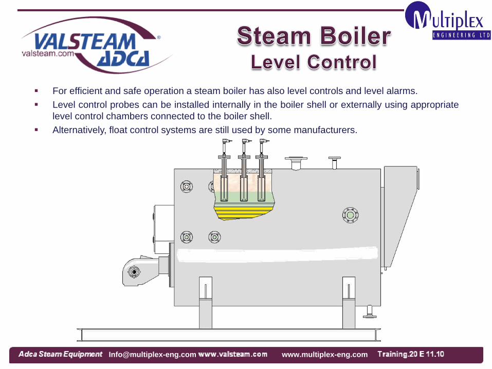
For efficient and safe operation a steam boiler has also level controls and level alarms.
Level control probes can be installed internally in the boiler shell or externally using appropriate
level control chambers connected to the boiler shell.
Alternatively, float control systems are still used by some manufacturers.
www.multiplex-eng.com [email protected]

Water quality is extremely important on the exploration of a thermal power station. The use
of hard water or poorly treated water may cause accidents or irreparable damages on the
generator and piping, apart from decreased heat transmission.
Water quality control must be done periodically. An effective treatment must keep it within
the required parameters.
Generally, water for a heat generator must be less hard as possible (≤1ºfH), be free of
suspension solids, have alkaline Ph (8,5 minimum) and low in O2 (≤ 0,02mg/l) and CO2.
www.multiplex-eng.com [email protected]

Most current process of reducing water hardness is through ion-exchange method:
The raw water is guided through heavy-duty resin which has been enable by exchanger-
active sets to exchange cations or anions. The calcium and magnesium ions are absorbed
during the softening procedure while adequate amounts of sodium ions capable of
exchange (Na+) are released into the water. The exchange resin has physically
conditioned a limited capacity and is exhausted after a certain number of water
throughputs. The regeneration of the water softening system is performed by means of a
salt solution.
Ph correction, which value is associated with CO2 content may be done through a
controlled injection of chemicals for which is necessary adequate dosing instruments.
O2 and CO2 can be eliminated by chemical or thermal process. The chemical process
uses sometimes some products non-recommended in food industry ,thus the thermal
process offers more advantages as:
O2 Elimination
CO2 elimination
And by consequence, Ph correction
www.multiplex-eng.com [email protected]

The timing of regeneration can be selected
manually or automatically .
If the softener is electronically controlled by a
timer, the regeneration has to be selected
outside the operational use of steam boilers.
The volumetric systems work in dependence
on the flow volume. The duplex design is
specially suitable for continuous operation,
because the regeneration is performed
alternatively without interruption of the soft
water supply.
www.multiplex-eng.com [email protected]

During the vaporisation process the
suspended solids in the boiler water
are collect in the bottom of the boiler in
the form of sludge.
Manual blowdown valves are specially
designed for application on steam
boilers removing the concentrations of
solids (sludges) avoiding boiler
damages, unstable water level control
and other typical problems.
The valves are provided with a manual
handwheel.
Valve aperture cycles depends from
the boiler manufacturer specification or
water treatment specialists.
VPA26S
(Manual)
www.multiplex-eng.com [email protected]
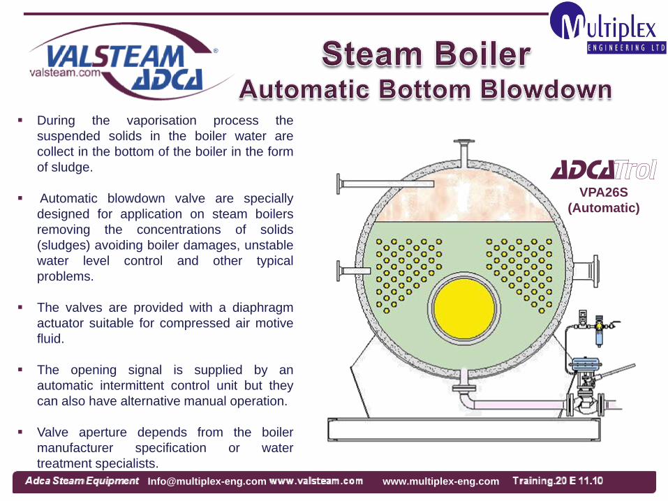
During the vaporisation process the
suspended solids in the boiler water are
collect in the bottom of the boiler in the form
of sludge.
Automatic blowdown valve are specially
designed for application on steam boilers
removing the concentrations of solids
(sludges) avoiding boiler damages, unstable
water level control and other typical
problems.
The valves are provided with a diaphragm
actuator suitable for compressed air motive
fluid.
The opening signal is supplied by an
automatic intermittent control unit but they
can also have alternative manual operation.
Valve aperture depends from the boiler
manufacturer specification or water
treatment specialists.
VPA26S
(Automatic)
www.multiplex-eng.com [email protected]

Some impurities remains in the boiler water in the form of dissolved solids and so they cannot
be eliminated trough the bottom blowdown. The concentration of this dissolved solids naturally
increase with steam production. When this concentration is
high, and in order to restore
the right levels, some of the
boiler contents must be
purged. Lost water will be
replaced by lower TDS
concentration feedwater,
replacing the correct
parameters.
A typical problem of excess
TDS concentration is water
foaming which origins bad
boiler performance and wet
steam.
www.multiplex-eng.com [email protected]

Blowdown controller
Adcatrol
Blowdown control valve
Conductivity
probe
To BEX for expansion and
drain or flash vessel for
energy recovery.
Sample Cooler
When the TDS concentration reaches the set point measured by the conductive probe,
a controller gives an open signal to the blowdown valve.
Boiler manufacturer and water treatment specialists
usually indicates the maximum permissible
concentration.
www.multiplex-eng.com [email protected]

The blowdown and cooling units are used in the modern boiler houses to cool hot
waste water and steam boiler blowdown before to discharge into a pit or drain to
prevent thermal pollution and pipe system damages. The waste water is discharged
into the unit which is at atmospheric pressure and the cooling water enters via a
control valve controlled by a thermostat, mixing with the hot water .
If flash steam can not be recovered or discharged to atmosphere an additional
condensing water spray system (optional) can be supplied . This one is fitted in the
top of the unit and can be controlled directly
either by another thermostat or the
same command used for the
automatic blowdown
valve control .
EH
Exhaust Head
BEX
Blowdown
Expansion Vessel
www.multiplex-eng.com [email protected]

Sample coolers prevent steam flashing-off from hot pressurised liquid samples, which
can be dangerous and will result in an incorrect water sample.
Basically they operate as a small heat exchanger.
Hot Sample IN
Cooling Water
OUT
Cooling Water
IN Cold Sample
OUT
Cooling Water
OUT
Cooling Water
IN
Hot Sample IN
Cold Sample
OUT
SC32 SC32/F
www.multiplex-eng.com [email protected]

For high pressure boilers and continuous analysing, special execution is necessary.
Clean steam systems also require a specific design and finishing surfaces.
SC332
SC432
SC532
Ts= 550ºC
Ps=245 bar
SC32P
Clean Steam
Internal Finished
to 0,5 micronsRa
www.multiplex-eng.com [email protected]

One of typical applications for the use of
flash vessel is precisely in recovering flash
steam from the boiler blowdown.
This energy recovery can be used for
feedtank preheating, saving fuel.
Flash steam produced can be condensate
inside the vessel by using injectors
submerged in the water or it can simply be
used on the deaerator head.
Flash steam
Blowdown from
boiler
Contaminated
water
Adca
RV.../A
Flash Vessel
www.multiplex-eng.com [email protected]

Condensate Flash Steam
Make up Water
Hot Water
Cold Water
Heat Recover from
Residual Blowdown
Flash Vessel
ADG
Atmospheric Thermal Deaerator
with Dome Flash Steam Inlet
www.multiplex-eng.com [email protected]

Since many years ago it is common to recover condensate from steam systems to the boiler feed tank, saving water and energy, reducing water treatment chemicals, costs and consequently reducing CO2 emissions.
In some systems, the amount of recovered condensate and correspondent temperature is so high that the water feed tank temperature rise to the boiling point. Thus, most of the recoverable energy is lost in the form of flash steam through the vessel vent pipe. Besides, boiler feed pumps can cavitate (see NPSH) and be damaged.
FRECO – Flash Steam Heat RECOvery, consider the energy recovery downstream of boiler feed pump. High pressure avoids the water boiling. (FRECO can be supplied as a skid mounting system for easy installation and commissioning).
A raised of 6ºC in feed water temperature, corresponds to a saving of approximately 1% fuel.
www.multiplex-eng.com [email protected]

A thermal deaerator is actually a deaerating feed water heater, which combines water heating, storage and deaeration capabilities.
Water is stored in a under pressure vessel typically about 3 bar g in order to aloud it to be kept at a temperature above 100ºC.
Thermal deaeration takes place in equipments especially designed for the job. There are existing two main kinds:
Tray type deaerators
Spray nozzle type deaerators
Tray type is by far the most used doing to is simplicity, versatility and performance.
Atmospheric deaerators also called partial deaeration systems or semi-deaerators are most times the economic choice for boiler capacities up to approximately 2000 Kg/h.
www.multiplex-eng.com [email protected]

Atmospheric semi-deaerators are designed to
heat boiler feed water and to reduce oxygen and
carbon dioxide (oxygen values in the feed water of
less than 1,6 mg/l , can be achieved). Remaining
oxygen can be completely removed using oxygen
scavenging chemicals.
Basically the complete system consists of a
storage vessel, a deaeration head section and a
vent.
Hot return condensate is injected in the bottom of
the storage vessel using an adequate sparger pipe
and softened make-up water is introduced in the
deaerator head to be heated by a contact cascade
flash steam heating system (counter-current flow)
coming from the vessel. Part of dissolved gases are
liberated from the water at this point and they are
liberated to atmosphere trough the flash steam vent
line .
The semi-deaerated water then falls to the
storage vessel below, where a steam injection
system will provide an additional deaeration.
Make up
Water
Flash
steam
Condensate
Recirculation
Condensate
Vent
ADG
Atmospheric
Semi-Deaerator
Dome
www.multiplex-eng.com [email protected]

Complete unit supplied including
all the necessary instrumentation
for temperature and level control.
Make up
Water
ADG/V
Complete unit
www.multiplex-eng.com [email protected]

Thermal deaerators are designed to heat boiler
feed water and to reduce oxygen and carbon
dioxide (oxygen values in the feed water of less
than 0,02 mg/l - 0,02 ppm, can be achieved).
Remaining oxygen can be completely removed
using oxygen scavenging chemicals.
Basically the complete system consists of a
storage vessel, a deaeration section and a vent.
Return condensate and softened make-up water
are introduced in the deaerator dome to be heated
by a contact cascade steam heating system
(counter-current flow). The majority of dissolved
gases are liberated from the water at this point and
they are liberated to atmosphere trough the flash
steam vent line.
The deaerated water then falls to the storage
vessel below, where a steam blanket ensure that
no gases are reabsorbed.
A sparger pipe is installed inside the tank at the
bottom level providing the necessary heating
energy. A second low pressure steam supply can
also be necessary (double stage).
TDG
Thermal Deaerator
Dome
Double Stage
Make up Water Condensate
Steam
www.multiplex-eng.com [email protected]

Complete unit
supplied including
all the necessary
instrumentation for
temperature,
pressure and level
control.
TDG/V
Complete unit
Make up Water
Condensate
www.multiplex-eng.com [email protected]
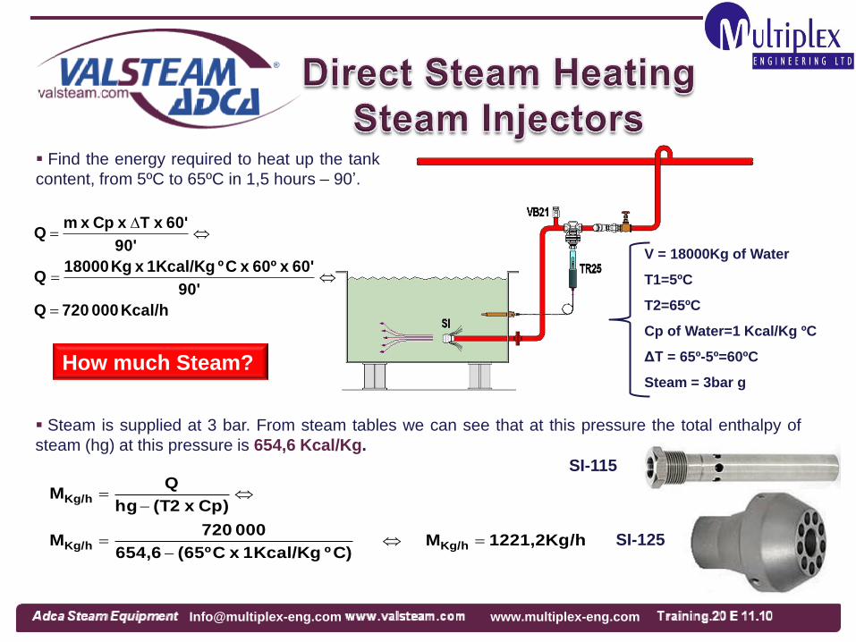
Find the energy required to heat up the tank
content, from 5ºC to 65ºC in 1,5 hours – 90’.
V = 18000Kg of Water
T1=5ºC
T2=65ºC
Cp of Water=1 Kcal/Kg ºC
ΔT = 65º-5º=60ºC
Steam = 3bar g
Kcal/h 000 720 Q
90'
60' x 60º x Cº 1Kcal/Kg x Kg 18000 Q
90'
60' x T x Cp x m Q
How much Steam?
Steam is supplied at 3 bar. From steam tables we can see that at this pressure the total enthalpy of
steam (hg) at this pressure is 654,6 Kcal/Kg.
1221,2Kg/hM C)º Kcal/Kg 1 x C(65º654,6
000 720M
Cp) x (T2hg
QM
Kg/hKg/h
Kg/h
SI-125
SI-115
www.multiplex-eng.com [email protected]

Using the same formulas it is possible to find the steam flow rate necessary to heat the tank material
and depending from insulation, ambient temperature, vessel design, etc, it is also possible to determine
the steam flow rate necessary to make up for the heat losses from radiation and water surface. Practical
calculation may accept an allowance based in a percentage of around 10%.
So, for our example we will consider 1221,2 Kg x 1,1 = 1343,4 Kg/h of steam.
NOTE: The tank must have enough free volume for the mass of steam added during the heating
process, 1343,4 Kg x 1,5 hr = 2015,10Kg.
The final water volume will be than 18000Kg + 2015,10Kg = 20015,10Kg.
At 3 bar the SI 140 has a capacity of 800 Kg/h, so, for the application we need
Steam Injectors SI 140 or Steam Injectors SI 125 268,1800
4,1343 598,4
270
4,1343
The vessel design, dimensions and the particular application may recommend the use of one
single big injector or more small units, with the equivalent total capacity.
www.multiplex-eng.com [email protected]

Hot water (or other fluids) storage vessels for
industrial purposes can be divided in two types:
Accumulators
Semi-instantaneous
Any of these can be equipped with internal coils
or external heat exchanger.
In the first case there’s a pre determined lack of
time for heating a quantity of fluid that is ready to
be used. In this case, coil or heat exchanger’s
regeneration capacity during consumption
process is not particularly relevant.
On the second case there’s a combination
between accumulated volume and capacity of
instantaneous heating. These two parameters
combined must assure the maximum
consumption calculated.
ADCATHERM WAVE
with external STSV
Heat Exchanger
www.multiplex-eng.com [email protected]

Heavy fuel oils and other viscous fluids are
stored in tanks heated by pipe coils or other
alternative systems. This is necessary to provide
the necessary temperature (viscosity) for
pumping. Too high temperature can represent
less viscosity and pump cavitation problems. So,
temperature control and correct condensate
drainage can be crucial.
Heating Coils can also be used to heat water
in closed or open vessels.
Mainly on fuel oil systems and semi-
instantaneous heaters the coil is frequently
supplied with a sleeve, heating the oil locally as
it is pumped out of the tank.
The use of extruded low fin tube , has the
advantage that it can improve the external
surface and thermal performance (Adcatherm R-
Coils).
BM20
www.multiplex-eng.com [email protected]

Heat exchangers are equipments designed to
transfer primary heat from one fluid to another.
Shell and tube heat exchangers are very popular for
steam to water heating since they can be designed
for any temperature and has relatively low cost
maintenance.
Plate heat exchangers can also be used on steam
applications under certain conditions, however,
maintenance is more expensive doing to the high
cost of gaskets.
Ready to install packaged units including heat
exchanger, control valve, steam trapping system and
all the necessary accessories, are recommended
since as a rule they save time installation, while
guaranty the correct assembly of all critical
components.
www.multiplex-eng.com [email protected]

TUBE SIDE SHELL SIDE
FLUID SATURATED STEAM WATER
OPERATING PRESSURE bar bar
INLET TEMPERATURE º C * º C
OUTLET TEMPERATURE º C * º C
FLOW RATE Kg/h * Kg/h or m3/h
HEAT EXCHANGED (Option) KW or Kcal/h
MODEL REQUIRED (Please select) STH (Horizontal) STV(Vertical)
Remarks :
* Not necessary in case of saturated steam.
STH – Horizontal installation ; STV – Vertical
installation.
TUBE SIDE VESSEL SIDE
FLUID SATURATED STEAM WATER
OPERATING PRESSURE bar bar
INITIAL TEMPERATURE -------------- º C
FINAL TEMPERATURE -------------- º C
VESSEL CAPACITY -------------- Kg or m3
INITIAL HEATING TIME (In minutes) ‘
RECOVERY PERIOD (In minutes)
HEAT EXCHANGED (Option) KW or Kcal/h
VESSEL TYPE (Please select) HORIZONTAL VERTICAL
AVAILABLE DIMENSIONS (Send a sketch) Straight length mm Diameter mm
HOT WATER CONSUMPTION m3
INCOMING COLD WATER TEMPERATURE º C
DESIRED HOT WATER TEMPERATURE º C
LENGTH OF TIME (IN MINUTES) ‘
If the vessel is also operating as semi-instantaneous hot water heater,
please confirm :
Remarks : A coil in a cylindrical vertical vessel should be as close to
but not exceeding the diameter of the vessel as possible. A coil in a
horizontal vessel is typically approximately 2/3 the length of the vessel Before installing an instantaneous heat
exchanger, one must certify that there’s a sufficient
steam flow or primary energy available for the
effect.
Storage vessels and semi-instantaneous
systems can be inconvenient since they need
more installation space. However, by balancing
with initial heating time and the accumulation
capacity it’s possible to avoid undesired highs of
energetic consumption .
Heat Exchanger Storage Hot Water Vessels – Closed Type
Semi – Instantaneous Hot Water Heater
www.multiplex-eng.com [email protected]

The steam/water Adcamix mixers provide cheap, instant
source of low pressure hot water by utilising existing steam
and cold water supplies.
The mixer incorporates a safety device to ensure that live
steam cannot accidentally be ejected, even if for some
reason the cold water supply fail.
The temperature of water at the outlet of the Adcamix is
easily controlled by using water and steam valves fitted to
the inlets.
www.multiplex-eng.com [email protected]

Air heating of large industrial spaces
can be made through multiples
systems available nowadays (gas,
electricity, hot water, steam, etc).
A steam to air unit heater is
composed by a coil and a fan, which
forces air passage through the coil in
order to heat it.
Steam air heating batteries can also
be used in central air conditioning
units combined with filtration
modules, direct steam humidification,
etc.
Co
nd
en
sate
High pressure
Live steam
Steam to Air
Unit Heater
www.multiplex-eng.com [email protected]

From higher pressure plants where the condensate enters into the vessel, the
flash steam is separated from the condensate. Through the top main connection of
the flash vessel the flash steam is then supplied to the lower pressure steam
network. The remaining condensate is discharged by an automatic float steam trap.
(See Adca Training I).
Installation of a flash vessel is
particularly convenient when both high
and low pressure steam equipments
are present in the same plant since
high pressure condensate can
generate low pressure steam.
To maximize the use of flash
vessels, it is convenient to design
them for the lowest possible pressure.
Model RV.../A
Blowdown
from boiler
Remaining
condensate
Flash Steam
ADCA
Flash Vessel
Model RV.../L
www.multiplex-eng.com [email protected]

High pressure
Live steam Low pressure
Steam application
Fla
sh
ste
am
Condensate
Flash vessel
RV…/L
www.multiplex-eng.com [email protected]
www.multiplex-eng.com [email protected]