Adaptive control systems_for_machining
10
r INTRODUCTION D uring the past two decades the number of comput- erized numerical controlled (CNC) systems has grown tremendously in almost every field of manu- facturing. A common drawback of these systems is that their machining control variables, such as speeds or feed- rates, arc prescribed by a part programmer and consequently I depend on his or her experience and knowledge. In order to reduce the chance of a tool failure. the part programmer must Il consider the most adverse conditions (which in practice will seldom occur), and select conservative values for the machin- ing variables. This practice consequently slows down the sys- t tem's production (lJ. The availability of a dedicated computer in the control system and the need for higher productivity has greatly accel- erated the development of adaptive control (AC) systems for metal cutting [2J. These systems are based on real-time con- trol of the cutting variables with reference to measurements of the machining process state-variables. The adaptive control is basically a feedback system that treats the CNC as an internal unit (see Fig. I), and in whieh the machining variables auto- matically adapt themselves to the actual conditions of the ma- chining process. AC systems for machine tools can be classified into three categories [3, 4]: (1) adaptive control with optimization (ACO), (2) adaptive control with constraints (ACe), and (3) geometric adaptive control (GAC). ACO refers to systems in which a given performance index (usually an economic func- tion) is extremized subject to process and system constraints. With ACC, the machining variables are maximized within a MANUFACTURING PERSPECTIVE Adaptive Control Systems for Machining YORMI KOREN Dept of Mechanical Engineering and Applied Mechanics, The University of Michigan, Ann Arbor, MI 48109 This paper summarizes the nutjor research e;1J'01'ts in th.e area of adaptive control for mac1lining processes in the last 2.5 years. The objectil'e of these adaptil'e contml systems 1'S toimprOl'e the production rate or the part quality by real-time setting of the optimal machining variables. In conventional GNG systems the machining variables are prescribed. by part programmers, and there fare, theirvaf;ues depend on the experience and process-knowledge of these programmers. By contrast, the adaptive control system the variables in real time, based upon measurements of other process Ilariables, 'rherej"ore, i.mprovementsin the peiformance of the overall system can be achie!led by using adaptive control methods. 1 I<'ig. 1. Adaptive control system for machine tool. prescribed region bounded by process and system constraints, such as maximum force or power. ACC systems, however, do not use a performance index and their operating point is always on the constraints. In GACs the part quality is main- tained in real time by compensating for the deflection and wear of cutting tools. By their definitions ACC systems usu- ally applied in rough cutting and GAC systems in finish oper- ations. In all systems an adaptation strategy is used to vary the machining variables in real time as cutting progresses. Note that while this type of system is termed adaptive in the manufacturing literature, it is not an adaptive system in the sense defined in the control literature [5-8]. © Copyright 1989 American Society of Mechanical Engineers 6
-
Upload
nakul-surana -
Category
Documents
-
view
60 -
download
3
Transcript of Adaptive control systems_for_machining

r
INTRODUCTION
During the past two decades the number of computerized numerical controlled (CNC) systems has grown tremendously in almost every field of manufacturing. A common drawback of these systems is
that their machining control variables, such as speeds or feedrates, arc prescribed by a part programmer and consequently
I depend on his or her experience and knowledge. In order to reduce the chance of a tool failure. the part programmer must Il consider the most adverse conditions (which in practice will seldom occur), and select conservative values for the machining variables. This practice consequently slows down the sys
t tem's production (lJ. The availability of a dedicated computer in the control
system and the need for higher productivity has greatly accelerated the development of adaptive control (AC) systems for metal cutting [2J. These systems are based on real-time control of the cutting variables with reference to measurements of the machining process state-variables. The adaptive control is basically a feedback system that treats the CNC as an internal unit (see Fig. I), and in whieh the machining variables automatically adapt themselves to the actual conditions of the machining process.
AC systems for machine tools can be classified into three categories [3, 4]: (1) adaptive control with optimization (ACO), (2) adaptive control with constraints (ACe), and (3) geometric adaptive control (GAC). ACO refers to systems in which a given performance index (usually an economic function) is extremized subject to process and system constraints. With ACC, the machining variables are maximized within a
MANUFACTURING PERSPECTIVE
Adaptive Control Systems for Machining YORMI KOREN Dept of Mechanical Engineering and Applied Mechanics, The University of Michigan, Ann Arbor, MI 48109
This paper summarizes the nutjor research e;1J'01'ts in th.e area of adaptive control for mac1lining processes in the last 2.5 years. The objectil'e of these adaptil'e contml systems 1'S toimprOl'e the production rate or the part quality by real-time setting of the optimal machining variables. In conventional GNG systems the machining variables are prescribed. by part programmers, and therefare, theirvaf;ues depend on the experience and process-knowledge of these programmers. By contrast, the adaptive control system adju.~ts the variables in real time, based upon measurements of other process Ilariables, 'rherej"ore, i.mprovementsin the peiformance of the overall system can be achie!led by using adaptive control methods.
1
I<'ig. 1. Adaptive control system for machine tool.
prescribed region bounded by process and system constraints, such as maximum force or power. ACC systems, however, do not use a performance index and their operating point is always on the constraints. In GACs the part quality is maintained in real time by compensating for the deflection and wear of cutting tools. By their definitions ACC systems usually applied in rough cutting and GAC systems in finish operations. In all systems an adaptation strategy is used to vary the machining variables in real time as cutting progresses.
Note that while this type of system is termed adaptive in the manufacturing literature, it is not an adaptive system in the sense defined in the control literature [5-8].
© Copyright 1989 American Society of Mechanical Engineers 6

Although there has been considerable research on the development of ACO systems, few, if any, of these systems are used in practice [9]. The major problem with such systems has been the lack of suitable sensors which can reliably measure on-line the necessary process variables (e.g., tool wear) in a production environment. Most commercial AC metal-cutting systems which are used in industry today are of the ACC and GAC types, and seldom involve the control of more than one machining variable.
The objective of most ACC systems is improvement in producti vity, which is achieved by increasing thc metal removal rate (MRR) during rough cutting operations. Several studies have been published [3, 10-13] which present the productivity increase achieved with ACC system as compared to conventional machining. The increascs in productivity range from approximately 20 to 80 percent and clearly depend on the material being machined and the complexity of the part to be produced. The AC systems show the most marked advantages in situations where there are wide variations in the depth of cut during maehining.
The objective of GAC is to achieve (I) the required dimensional accuracy and (2) a consistency of surface finish of machined parts [14]. Both the dimensional accuracy and the surface finish are affected by the flank wear and the crater wear of the tools which deteriorate during cutting. These variables cannot be measured in real time; meither can they be accurately predicted from off-line tool testing. Therefore. the GAC approach usually taken is that the tool is assumed to be worn out when the above criteria, (1) or (2), are no longer at acceptable values. This method has been found to correlate well in practice with actual tool deterioration [15].
Saving of time is achieved when applying AC systems in the programming stage. Since the machining variables, such as speeds and feedrates, are adjusted automatically by the system, the part programmer does not have to spend time and effort calculating their optimal values. Again, this time savings becomes significant in complex parts where wide variations in depth of cut must be accommodated. Other savings are associated with reduced tool wear [16] and the control of chatter [17-19].
ADAPATIVE CONTROl, "VITH OPTIMIZATION
The most-known research for ACO systems for milling (turning is a similar problem) was conducted at Bendix during the years 1962 through 1964 under the technical supervision of the U.S. Air Force [20]. The block diagram of the Bendix system is shown in Fig. 2. The sytem consists of a milling machine, NC controller, sensors unit, and adaptive controller. The sensors measure the cutting torque, tool temperature, and machine vibration. These measurements are used by the adaptive controller to obtain the optimal feedrate and spindle speed values as will be explained later.
The adaptive controller contains a data reduction subsystem (DRS) fed by the sensor measurements as well as by the calculated feed rate and spindle speed and a set of constraints. The DRS produces two signals: a metal removal rate (MMR) and a tool wear rate (TWR). The MRR is the product of the milling width (w), the depth of cut (a), and the milling feedrate (V) in inches per minute:
MRR = waY (1)
Fig. 2. ACO System for a milling machine.
The MRR is used in the calculation of the TWR value:
(2)
where Il is the tOOl .cmperature, aTIdt is the time rate of change of the cutting torque, and K j , K2 , and K3 are constants which depend on the tool and workpiece materiaL
The 1WR and MRR signals are fed into a performance computer which calculates the performance index <i> as follows:
where
C j cost of machine and operator per unit time C2 cost of tool and regrind per change tj tool changing time
Wo terminal allowable width of the tool's flank wear ~ adjustable parameter (0 < ~ < 1) which deter
mines the type of performance index (PI): If ~ = I the PI is the reciprocal cost per unit. If ~ = 0 the PI is the production rate. If 0 < ~ < 1 the PI takes into account both the cost per part and the production rate.
The calculated index <i> is fed into an optimization computer unit which contains the strategy according to which the optimization is performed. The objective of this unit is to continually maintain the value of <i> at the highest possible value without causing any constraint violations. Examples of constraints are maximum and minimum spindle speed, maximum torque, maximum feed, maximum temperature, and maximum vibration amplitude.
Although considerable efforts were expended in the Bendix project, it was not commercially accepted. The main
Koren: Adaptive Control Systems for Machining 7

problem is that this, and other similar ACO systems for milling and turning, require on-line measurement of tool wear [21-25]. So far there have been no industrially acceptable methods developed for the direct measurement of tool wear. Indirect measurement assumes that tool wear is proportional to other measurable variables such as cutting forces and temperatures. The drawback of using these indirect measurements is that variations in their values can be caused by process variations other than tool wear, such as workpiece hardness or cutting conditions, thus making it difficult to identify the tool wear effect from the effect of the other parameter variations on the measurements. The Bendix researchers estimated the tool wear rate according to Eq. (2). However, since the constants Kj, K2 , and K3 in Eq. (2) depend on the tool and workpiece material, to use the Bendix system the user needs to perform off-line experiments to determine the values of these constants for every combination of tool and workpiece material. The time and effort needed for these experiments may override the economic benefits of the AC system.
The lack of a reliable tool wear sensor is the main obstacle in developing industrial ACO systems for milling, drilling, and turning [26]. Although a few techniques were developed to measure the flank wear on turning tools in laboratories [27]-these methods cannot be utilized on the production floor. The problem in milling and drilling is even more difficult because of the complex geometry of milling cutters and twist drills [28]. Experimental ACO systems, however, have been implemented in grinding [29], in which a power or a force sensor can provide information about the wear of the grinding wheel.
ADAPTIVE CONTROl, WITH CONSTRAINTS
We have seen that considerable research and development are required before ACO systems become practical for industrial use. Actually all the AC systems for rough turning and milling used in production today are of the ACC type and seldom involve control of more than one machining variable [30-31). Unlike ACO, ACC systems do not utilize a performance index and are based on maximizing a machining variable (e.g., feedrate) subject to process and machine constraints (e.g., allowable cutting force on the tool, or maximum power of the machine).
The objective of most ACC types of systems is to increase the MRR during rough cutting operations. This is achieved by maximizing one or more machining variables within a prescribed region bounded by process and system constraints [3, 32-34]. One useful approach, for example, is to maximize the machining feedrate while maintaining a constant load on the cutter, despite variations in width and depth of cut [35-38]. This is illustrated in Fig. 3 for a slab milling operation. In a normal CNC system, the feedrate is programmed to accommodate the largest width and depth in a particular cut, and this small feed rate is maintained along the entire cut. As a result the machining rate is reduced. By contrast, with the ACC system, the maximum allowable load (e.g., cutting force) on the cutter is programmed. As a result, when the width or depth of cut are small the feedrate is high; when either the width or depth of cut (or both) are increased, the feedrate is automatically reduced, and consequently the allowable load on the cutter is not exceeded. The result is, the average feed with ACC is much larger than its programmed counterpart. Likewise, when the tool moves through air gaps in the workpiece, the feedrate reaches its maximum allowable
8
I
Fig. 3. The reedrate command in conventional and adaptive controlled CNC machine.
value. Operating at the maximum allowable feedrate, maximizes the MRR (See Eq. 1). The ACC system guarantees maximum productivity while minimizing the probability of cutting tool breakage.
Commercial AC systems are available for end milling. An end milling cutter may break in bending or in torsion or a tooth may break away. An appropriate ACC system must therefore continuously check the radial cutting force and the cutting torque on the cutter, and vary the feedrate so as to keep both these variables below the permissible limit [39].
The most commonly used constraints in ACC systems are the cutting force, the machining power, and the cutting torque [27. 40]. The operating parameters are usually the feedrate velocity V (in millimeters per minute or inches per minute) and the spindle speed N (in revolutions per minute); both can be easily manipulated under computer controL The machining feed f is defined by the ratio
f V/pN (4)
where p is the number of teeth in the cutter in the milling operation; in turning and drilling p 1 is substituted in Eq. (4).
The main cutting force F is proportional to the depth of cut a and the feed:
F = K,aj" (5)
where K, is the specific cutting force, and u is a parameter in the range 0.6 < u < 1. Both K, and u depend on the workpiece and tool material. The cutting torque T is proportional to the force and the workpiece diameter in turning and the tool diameter in milling and drilling. The machining power P is proportional to the torque and the spindle speeds.
A typical computerized ACC system, which applies the concepts introduced in this section, is described for turning on a CNC lathe with a constant cutting force constraint [36]. The ACC system shown in Fig. 4, is basically a feedback loop where the feed adapts itself to the actual cutting force and varies according to changes in work conditions as cutting proceeds. The CNC computer executes the original control program and an additional AC routine, which is linked to the feedrate routine contained in the control program. The AC loop functions in a sampled-data mode. The actual main cut-
Manufacturing Review vol 2, no I, March 1989

Fig. 4. Basic structure of ACC system.
ting foree F is sampled every T seconds (typically T = 0.1 s), then converted to a digital signal F, and sent to the computer. The actual force representation Fe is immediately compared in the computer with a predetermined allowable reference force Fr. The difference between Fr and F,. which is the force error E (E = Fr - Fe) is used as the input to the AC controller. The latter sends a correction signal to the feedrate routine, which, in turn, produces the feedrate command nal. A positive error increases the feedrate and consequently increases the actual force, thereby decreasing the error E, and vice versa.
In order to eliminate completely the force error, the controller output command U should be proportional to the time integral of the force error W. The simplest structure for such an integral strategy can be written
W(i) = Wei 1) + TE(i) (6)
and then the command signal U from the controller is
(7)
Equations (6) and (7) can be combined to give a more efficient form for programming:
(8)
where K,., the controller gain, is proportional to the sampling period T, I.e., Kc TK;. The resulting computer feedrate command V I to the servo loops at the ith sampling (or to the interpolator in a multiaxial mode) is given by
(9)
where K I is a constant associated with the feedrate routine. The initial feedrate value K IUO may be preselected so as to avoid tool breakage when the tool initially impacts the workpiece at the start of the cutting process. As long as there is an error, the command U varies the machine feedrate in a direction to correct this error. At the steady state, however, the er-
Koren: Adaptive Control Systems for Machining
ror in the force is zero, causing the condition U(i) U(i - I), which means that the feedrate command is constant, maintaining the actual force equal to the required one.
This integral strategy has been implemented on a high-power CNC lathe [41]. A typical result for Kc 0.5 is shown in Fig. 5. The feed before engagement was selected as 0.5 mm/r. At the start of cutting, the feed is automatically reduced to approximately 0.25 mm/r. The depth of cut is increased by increments of 2 mm, and each time, after a small transient, the force reaches the preselected reference value of Fr = 1500 N, and the corresponding feed is decreased.
The selection of the gain K, is critical to the operation of the AC system. It is known from control theory that the lower the gain K" the greater the tendency for stability. Although a small gain causes a sluggish response, the steady-state error always becomes zero.
SELF-TUNING AC SYSTEMS
Proper selection of the controller gain Kc in ACC systems is very critical if wide variations in width or depth of cut, feed, and spindle speed are permitted in the system [13, 42]. The reason is that in AC systems, the machining process itself is part of the control loop as is shown in Fig. I. Therefore, variations in the process directly affect the control parameters of the loop, and consequently the AC system might become unstable.
The Stability Problem
The results of a turning experiment demonstrating the stability problem is given in Fig. 6. In this experiment the controller gain is Kc 0.6 and the sampling period is T 0.1 s. At the start of the cut the feed is automatically reduced and adapts itself to the programmed increase in the depth of cut. Note that the load force on the tool remains constant. However, the
Fig. S. Typical response of an ACC system.
9
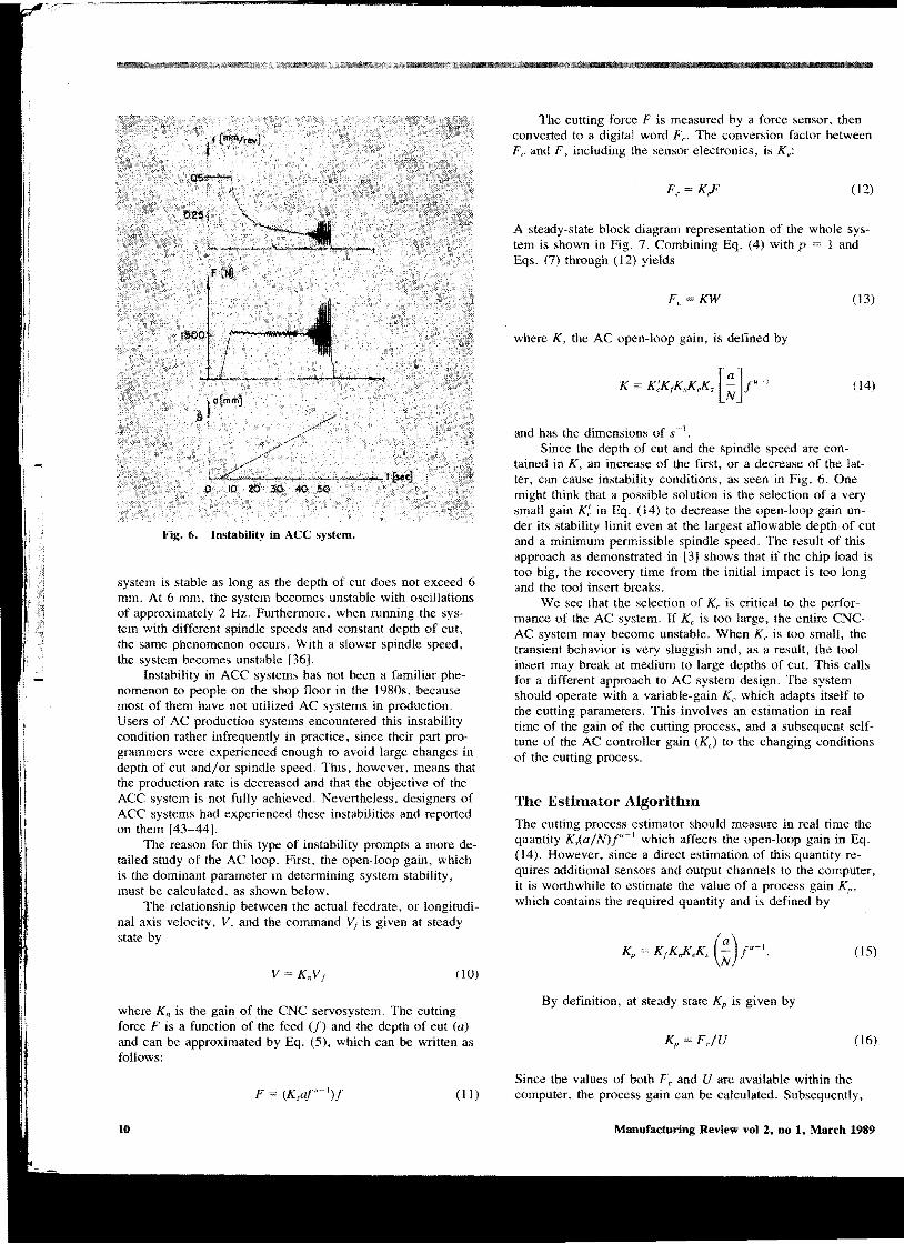
Fig. 6. Instability in ACC system.
system is stable as long as the depth of cut does not exceed 6 mm. At 6 mm, the system becomes unstable with oscillations of approximately 2 Hz. Furthennore, when running the system with different spindle speeds and constant depth of cut, the same phenomenon occurs. With a slower spindle speed, the system becomes unstable [36].
Instability in ACC systems has not been a familiar phenomenon to people on the shop floor in the 1980s, because most of them have not utilized AC systems in production. Users of AC production systems encountered this instability condition rather infrequently in practice, since their part programmers were experienced enough to avoid large changes in depth of cut and/or spindle speed. This, however, means that the production rate is decreased and that the objective of the ACC system is not fully achieved. Nevertheless, designers of ACC systems had experienced these instabilities and reported on them [43-44].
The reason for this type of instability prompts a more detailed study of the AC loop. First. the open-loop gain, which is the dominant parameter in determining system stability, must be calculated. as shown below.
The relationship between the actual feedrate, or longitudinal axis velocity, V. and the command Vj is given at steady state by
V KnVj (10)
where Kn is the gain of the CNC servosystem. The eutting force F is a function of the feed (f) and the depth of eut (a) and can be approximated by Eq. (5), which can be written as follows:
F = (K,ar-l)f (II)
The cutting force F is measured by a force sensor. then converted to a digital word Fe. The conversion factor between Fe and F, including the sensor eleetronics, is Ke:
Fe K,F (12)
A steady-state bloek diagram representation of the whole system is shown in Fig. 7. Combining Eq. (4) with p = 1 and Eqs. (7) through (12) yields
Fe KW (13)
where K, the AC open-loop gain, is defined by
K = K;KrKnKeKs [~]r-l (14)
and has the dimensions of s-] . Sinee the depth of cut and the spindle speed are con
tained in K, an increase of the first, or a decrease of the latter, can cause instability conditions, as seen in Fig. 6. One might think that a possible solution is the selection of a very small gain K: in Eq. (14) to decrease the open-loop gain under its stability limit even at the largest allowable depth of cut and a minimum pennissible spindle speed. The result of this approach as demonstrated in [3] shows that if the chip load is too big, the recovery time from the initial impact is too long and the tool insert breaks.
We see that the selection of Kc is critical to the performance of the AC system. If Ke is too large, the entire CNCAC system may become unstable. When Kc is too small, the transient behavior is very sluggish and, as a result, the tool insert may break at medium to large depths of cut. This calls for a different approach to AC system design. The system should operate with a variable-gain Kc which adapts itself to the cutting parameters. This involves an estimation in real time of the gain of the cutting process, and a subsequent selftune of the AC controller gain (Ke) to the changing conditions of the cutting process.
The Estimator Algorithm
The cutting process estimator should measure in real time the quantity K,(a/N)f"-l which affects the open-loop gain in Eq. (14). However, since a direct estimation of this quantity requires additional sensors and output channels to the computer, it is worthwhile to estimate the value of a process gain Kp ,
which contains the required quantity and is defined by
Kp KrK.KeKs (~)r-I. (15)
By definition, at steady state Kp is given by
Kp FjU (16)
Since the values of both Fe and U are available within the eomputer, the process gain can be calculated. Subsequently,
Manufacturing Review vol 2, no 1, March 1989 10

the controller gain Ke (where Ke TK;) could be adjusted in real time according to the equation
(17)
where K is the desired open-loop gain. Direct implementation of the algorithm based upon Eqs.
(16) and (17) is not realistic because Fe is a noisy measurement and the resultant Kc will follow the noise signal rather than optimizing the process. Therefore, techniques used in estimation theory should be applied. One such technique is shown in Fig. 8. The estimated model block contains an estimated gain Km, which is mUltiplied by the input U to generate an estimated force Fe. In general, K", = Kp , and an error Em is generated:
(18)
Since at steady state Fe UKp , the model estimation error is
(19)
The estimated model gain Km should be automatically adjusted to reduce this error. The simplest adjustment policy which guarantees a zero error is to apply an integration algorithm:
(20)
With this algorithm, when the error Fm is zero, K", is a constant which satisfies Km Kp. In the computer program this estimator algorithm is given by the following equations:
FmU + I) = Fe(i) U(i)Km(i) (21 )
Km(i + I) KnI(i) + K1Em(i + 1). (22)
The specific value of Kl depends on the amount of noise in the measured force. In the presence of high-level noise, the estimator gain must be small in order to smooth the noise and estimate the process parameter K", with good precision. This, however, causes the disadvantage of slower convergence to the steady-state value of Kw
Variable-Gain Algorithm
The objective of the variable-gain adaptive control algorithm is to maintain a constant open-loop gain despite variations in the cutting parameters [3, 45]. By combining Eqs. (14) and (15) the open-loop gain is defined by
(23)
and substitution of the estimated value Km for Kp yields
(24)
The constant open-loop gain can be obtained by adjusting the controller gain Kc according to variations of Km. As in the
Koren: Adaptive Control Systems for Machining
Fig. 7. Block diagram of an ACC system.
Fig. 8. Process estimation in a self-tuned ACC system.
case of the estimation algorithm, direct division is avoided and smoothing is achieved by using the following integration policy:
EcU + l) TK - KAi)Km(i) (25)
Kc(i + I) Kc(i) + K2EJi + l) (26)
Again, the integration algorithm in Eq. (26) guarantees that Ee = 0 at the steady state, which means that the desired overall gain can be achieved.
We see that the solution to the original problem is in the fonn of a supplementary adaptation loop. In the main loop the machining feed is adapted to maintain a constant load on the cutting tool, and in the supplementary loop the controller gain is adapted, or self-tuned, to maintain a constant loop gain despite variations in the cutting condition.
A set of experiments was perfonned to compare the perfonnance of a conventional AC system with the variable-gain AC system [46]. In these experiments the controller gain in the conventional AC was Kc 0.6, the sampling period T 0.1 s, and the integration constants in the variable-gain AC system were set to Kl K2 = 1/4. The objective of the experiment shown in Fig. 9 was to remedy the unstable conditions obtained in Fig. 6 for the conventional AC system. In Fig. 6, it can be seen that the conventional AC system became unstable for a depth of cut of 6 mm. By contrast, as is seen in Fig. 9, the variable-gain AC system was always stable. The value of Kc was automatically reduced from 1.5 to 0.33 with the progressive increase in the depth of cut.
The self-tuned AC system provides a solution to the stability problem which arises in conventional ACC systems when wide variations in width or depth of cut are needed.
11

I 't'7
I r·
Fig. 9. Response of a variable-gain ACC system to a varied depth of cut.
The solution does not require any additional hardware, and all the modifications to the AC controller are implemented by software.
GEOMETRIC ADAPTIVE CONTROL
Geometric adaptive control systems (GAC) are typically used in finish machining operations, where the objective is to achieve a desired surface quality and/or accurate part dimensions despite tool wear or tool deflection. Most of the practical GAC systems are available for turning, but research is conducted also for milling [47] and grinding. From the point of view of surface finish, turning should be accomplished at as high a cutting speed as possible [48]. Therefore, in most GAC systems the cutting speed is constant and the machining feed is manipulated to achieve the desired surface quality. The dimensional precision in turning is usually achieved by measuring the part diameter at various points after the machining, and compensating for inaccuracies by adding an offset distance to the cross-axis position-command on a lathe.
12
The tool geometry has a significant role upon the theoretical surface finish of the machined parts. Two equations are used in the literature [48]. For a tool without nose radius the maximum amplitude of surface roughness, h, is given by
h = f /(cot" + COtK,) (27)
where K" the tool cutting edge angle, has a typical value of 75°, and K" the tool minor cutting edge angle, has a typical value of 15°. For a tool with a large nose radius r a good approximation of the surface roughness amplitude is
h = f/8r (28)
As the tool wears, its nose geometry slightly changes, which, in tum, causes a change in the surface finish. From our experiences, the surface finish is usually improved during the first 10 to 20% of the tool life, then it stays at an almost steady level with a slight deterioration, and toward the end of the tool life it deteriorates very fast.
In a GAC system the surface roughness is measured online, either in-process or immediately at the end of the machining operations with the aid of a profilometer. The latter method fits turning on a lathe that typically has short machining time per part. For the purpose of GAC, Eqs. (27) and (28) may be combined to a model
h = cd+ cd2 • (29)
The coefficients c] and C2 depend on the variations in the material and the change in tool wear and might be identified by using time-varying least-squares algorithms [49]. These estimated coefficients are subsequently used by the AC algorithm to determine the feed required to achieve a specific surface finish.
Alternatively, time series methodology might be applied for the identification process. Fig. 10 shows some results achieved by this method in turning [50]. The required surface finish is Ra = 1.5 fLm (60 fLinch), where Ra is the center-line average. The required finish is achieved with a new tool at f = 0.23 mm/rev (0.009 ipr) as shown in Fig. lOa. Without AC, the CNC system always uses the same feed and the resultant surface finish deteriorates to RA = 3 fLm with a worn tool (Fig. lOb). For the same worn tool, the GAC system automatically reduces the feed to 0.15 mm/rev (0.006 ipr), a value which maintains the required surface finish (Fig. JOe).
Figure I 1 shows the surface finish and the adaptation of the feed (plotted versus workpiece number) on the same GAC system. The experiment was conducted on SAE 4140 steel with a carbide tool with r 0.032", cutting speed of 180 m/min (550 sfm), depth of cut 0.75 mm (0.03"), and an initial feed of 0.18 mm/rev (0.007 ipr). The surface finish is measured after the machining of a workpiece has been completed. As seen in the figure, the desired surface finish (60 fLinch) is achieved after 10 parts, and then enters to a steadystate region in which the feed is held essentially constant. The tool actually failed in this experiment after 47 parts (the feed rapidly raised in the failure region).
The second eriterion used in GAC systems is the dimensional accuracy of the produced part. In turning, the external diameters of the part increase as the tool wears. The reason is
Manufacturing Review vol 2, no 1, March 1989

Fig. 10. Plots oC surface roughness profile.
that the flank wear W at the tool nose reduces the effective tool length.
The principle of a GAC turning system that compensates for tool wear is simple. When the cut is completed, the system measures the external diameter of the part, and activates automatically the tool offset feature of the CNC system to compensate for the dimeasional error. If the cycle time per part is short, the next part will be produced at the desired dimension.
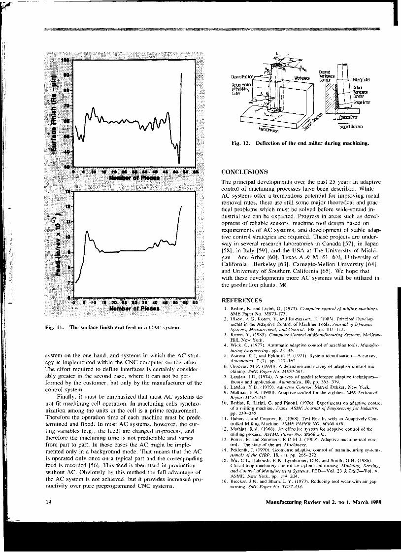
GAC is also used in milling operations with end-miller cutters. Because of the cutting forces that operate at their end, these cutters deflect and consequently cause dimensional errors. Figure 12 [44] shows the bending-moment components in the feed direction and support direction (MBv and M Bst), that are generated at the point where the tool is clamped by the cutter-deflection force, FA' The end of the milling cutter is deflected by an amount <)" in the feed direction and bSt in the support direction.
In the GAC system the machining operation is controlled in such a way that the maximum permitted cutter deflection omax and the given limit for the accuracy of the part bsi • bmax
are not exceeded. The control is performed using the bending moments Ms, M Bv• and M St as reference values with the feedrate as the control variable. A drawback of the system is that the function 0 = f(F;I) must be determined experimentally in each case for the particular tool/chuck/machine combination. Therefore, this system is used only in research laboratories and not in production lines.
LIMITATIONS OF' AC SYSTEMS
In spite of their economic advantages AC systems are not spread out in industry. A major reason for this situation is the unavailability of suitable sensors that have a reliable operation in a manufacturing environment [51-53J. The lack of a tool wear sensor is the major obstacle to the employment of ACO systems. Force and torque sensors for ACC systems are difficult to install. Cooperation with machine tool builders might facilitate the usage of sensors for AC systems [54]. For exam-
Koren: Adaptive Control Systems Cor Machining
pIe, the tool-holder of a machine tool might be designed in such a way that a cutting force sensor could be easily installed. Or the spindle bearing might be designed to accommodate torque measurements. In GAC systems the bottle neck is the cost of the optical measuring devices and their inability to operate in a machining environment with chips and coolant fluids. The reliability of all these sensors is very important, since failure almost always leads to a machine damage.
The type of control variable employed might be another reason for the low penetration of AC systems. We have seen above that in most AC systems the machining feed is the natural control variable. It increases with the cutting depth decreases and vice versa. Decreasing the feed with increasing cutting depth, however, results in an unsuitable area of the chip section and might make the chip breakage impossible. A similar situation occurs with very small depth and large feed. Furthermore, in both cases the cutting tool is overloaded in a manner that might cause a high wear rate or breakage of the cutting edge [55]. To avoid these situations researchers have tried to design feed-limited ACC systems in which the depth of cut becomes the control variable when the feed limit is reached [55]. These AC systems, denoted as Automatic Cut Distribution (ACD) systems, must include real-time computation of the tool path. The economic advantage of these ACD systems is questionable because of the unpredictable tool path that might require very long machining time.
For operation of ACC systems, nominal values (e.g., forces) must be preset according to the properties of the tool and workpiece material, the performance of the machine, and the technology of the cutting process. For retrieving these nominal values, the corresponding data of the machine and of the workpiece material must be stored in the ACC computer or the CAD system, so that the nominal values can be computed from these data. This computing strategy has yet to be developed.
Another problem is the interface of an AC system with CNC units. As yet, manufacturers have not standardized interfaces. One might distinguish between implementing an AC system as a background processor supplementary to a CNC
13
i
I It
···loc'~S'...;;a•••··.At····" .....~.Of.\,.....
Fig. 11. The surface finish and feed in a GAC system.
system on the one hand. and systems in which the AC strategy is implemented within the CNC computer on the other. The effort required to define interfaees is certainly considerably greater in the second case, where it can not be performed by the customer, but only by the manufacturer of the control system.
Finally. it must be emphasized that most AC systems do not fit machining cell operation, In maehining cells synchronization among the units in the cell is a prime requirement. Therefore the operation time of each machinc must be predetcrnlined and fixed. In most AC systems, however, thc cutting variables (c.g., the feed) are ehanged in-process, and therefore the machining time is not predictable and varies from part to part. In these eases the AC might be implemented only in a background mode. 'That means that the AC is operated only once on a typical part and the corresponding feed is recorded [56J. This feed is then used in production without AC. Obviously by this method thc full advantage of the AC system is not achieved, but it provides increased productivity over pure preprogrammed CNC systems.
14
/
~~~Em:r
_~ _f\JsltmEm:r
1Wii1Jm:!a1
.MIrg CutlEr
AdLd -~
CmIOO'
Fig. 12. Deflection of the end miller during machining.
CONCLUSIONS
The principal developments over the past 25 years in adaptive control of machining processes have becn described. While AC systems offer a tremendous potential for improving metal removal rates, there are still some major theoretical and practical problems which must be solved before wide-spread industrial use can be expected. Progress in areas such as development of reliable sensors, machine tool design based on requirements of AC systems, and development of stable adaptive control strategies are required. These projects are underway in several research laboratories in Canada [57], in Japan [58], in Italy [59], and the USA at The University of Michigan-Ann Arbor [60], Texas A & M [61-61], University of California-Berkeley [63], Carnegie-Mellon University [64] and University of Southern California [65]. We hope that with these developments more AC systems will be utilized in the production plants. l\R
RE}'ERENn;s
I, Bedini. R. and Lisini, G. (1973), Computer control of milling machines. SME Paper No, MS73-173.
2. Ulsoy. A G, Koren. Y. and Rasmussen, F, (1983), Principal Developments in the Adaptive Control of Machine Tools, Journal of Dynamic Systems. Measurement. and Control, 105. pp. J07-112.
3. Koren, Y, (1983). Computer Control of Mamifacturing Systems, McGrawHill. New York.
4. Wick. C. (1977). Automatic adaptive control of machine tools. Manufacturing Engineering. pp, 38-45,
5. Astrom, K J. and Eykhoff, p, (1971), System identification--A survey. Automatica, 7 (2), pp, 123-162.
6. Groover, M P. (1970). A definition and survey of adaptive control machining. SME Paper No. MS70-561.
7, Landau. I D, (1974). A survey of model reference adaptive techniques-· theory and application, AUiomatica, 10, pp, 353-379.
8. Landau, Y D, (1979), Adaptive Control, Marcel Dekker. New York. 9. Mathias. R A. (1980). Adaptive control for the eighties. SME Technical
Report M580-242. 10. Bedini, R. Lisini, G. and Pinolti, (1976), Experiments on adaptive control
of a milling machine. Trans. ASME Journal of Engineering for Industry, pp, 239-245
IJ. Huber, J, and Centner, R, (1968). Test Results with an Adaptively Controlled Milling Machine, ASME PAPER NO. MS68-638,
12. Mathias, R A, (1968), An effective system for adaptive control of the milling process, ASTME Paper No. MS68-202.
13. Porter. B. and Summers. R D M J, (1969), Adaptive machine-tool con· trol--The state of the art, Machinery.
14, Peklenik. J, (1970), Geometric adaptive control of manufacturing systems. Annals of the CIRP. 18. (I). pp, 265-212,
15, Wu, C L. Haooush, R K, Lymbumer. D R, and Smith, G H, (1986), Closed-loop machining control for cylindrical turning, Modeling, Sensing, and Control of Manufacturing Systems. PED-Vol. 23 & DSC-Vol. 4, ASME, New York, pp, 189-204,
16, Brecker. J N, and Shum. L Y. (1977), Reducing tool wear with air gap sensing. SME Paper No. 1'1"77-333,
Manufacturing Review vol 2, no 1, March 1989
17. Inamura. T. Senda. T. and Sata. T. (1977). Computer control of chattering in turning operation. Annals oj the CIRP. 25. (I). pp. 181-186.
18. Week. M. et al.. (1975). Adaptive control for face-milling operations with strategies for avoiding chatter-vibrations and for automatic cut distribution. Annals oj the ClRP. 24 (I). pp. 405-409.
19. Week, M. and Mueller. W. (1976). Chatter vibration sensors for adaptive control systems for turning and milling operations. The 4th NAMR Conference.
20. Centner. R. (1964). Final report on development of adaptive controltechniques for a numerically controlled milling machine. Technical Docum",,tary Report ML·TDR-64-279.
21. Colwell. LV. Frederick. J R, and Quackenbush. L J. (1969). Research in support of numerical and adaptive control in manufacturing. The University of Michigan. Ann Arbor.
22. DeFilippi. A. and Ippolito. R, (1969). Adaptive control in turning: cutting forces and tool wear relationship for PIO. P2(). P30 carbides. Annals oj the ClRP, 18. pp. 377-385.
23. Mathias. R A. (]976). Adaptive control for machining centers. SMF: Paper No. MS76-196.
24. Mathias. R A, Boock. W, and Welch. A. (1980). Adaptive control: Monitoring and control of metal-cutting processes. Proceedings oj the Machine Tool Task Force ConJerence, 4 (Sect. 7.13).
25. Takeyama H, Sekiguchi. H, and Takada K. (l97()). One approach for optimizing control in turning. J. oJ JSPE. 36 (5). pp. 311-317.
26. Novak, A, and Colding. B. (1964). Performance of AC systems m relation to measureable parameters. Annals oj the CIRP. 23 (l). pp. 33-34.
27. Cook. N H, Subramanian. K and Basile. SA. (1975). Survey of the stale of the art of tool wear sensing techniques. Massachusetts Institute of Technology.
28. Takeyamma H. Yamazaki. K, Yamada, A. and Sawai. N. (1974). A study on adaptive control in a NC milling machine. Annals or the CIRP. 23 OJ. pp. 153-154.
29. Amitay, G. Malkin S. and Koren Y, (1981). Adaptive control optimization of grinding. ASME Journal oj Engineering,l(;r Industn, 103 ( I). pp, 102-111.
3(). Abraham. R G. (1973). Westinghouse progress in adaptive control. Westinghouse Machine Tool Forum. Paper No. TP6.
31 Donahue. E J, (1976). Applications of adaptive control in the aerospace industry. SME Paper No. MS76·274.
32. Beadle. B R. and Bollinger J G. (1974). A constrained search adaptive controller for metal cutting. Second NAMR Canf. Prot:. pp. 267-284.
33. DeFilippi. A, and Ippolito. R. (1965). The influence of constraints on cutting conditions optimization, Annals of Ihe C1RP, 14, (I). pp. 417421.
34. Sata. T. et al.. (1975). Newly developed adaptive control systems of the turning process. CIRP Seminars on ManuJacturing Systems.
35. Beadle. B R. and Bollinger. J G, (1970). Computer adaptive control of a machine tool. Annals rif/he CIRP. 19 pp. 61-65.
36. Masory, O. and Koren. Y. (!9XO). Adaptive control system for turning. Annals afthe CfRP. 29, (I),
37. Nakazawa, K. (1976). Improvement of adaptive control of milling machine by non-contact cutting force detector. Proceedinfis oj the 16th Imernatiunal Machine Tool Design and Resl'arch ConJerence. pp. W9-116.
38. Tlusty. J. and Elbestawi. M, (1979). Constraints in adaptive control with flexible end mills. Annals oj the CIRP. 28. (I). pp. 253-255.
39. Tlusty. 1. and Koren, Y. (1974). Numerical and adaptive control for die sinking, Proc. oj the 2nd Imemational ConJerence or Production Engi, neering, Tokyo.
4(). Birla. S K, (l98(). Sensors for adaptive control and machine diagnostic,. Proceedinfis oj the Machine Tool Task Force COIlj'erence. 4. (Sect. 7.12).
41. "vlasory, O. and Koren. Y. (]9X3). Variable-gain adaptive control system for machine tools. Journal oj ManuJacturing Svstems, 2. (2). pp, 165174.
42. Mathias. R A. (1967). Adaptive control of the milling process. Proceed· ings oj the IEEE National Machine Tools Industry Conj'erence, Paper No. 34CP67·716.
43. Mathias. R A, (1977). Software adaptive control optimum productivity fur CAM. SME Paper Nu. MS77-252.
44. Stute. G, (1980). Adaptive control. Proceedings oj the Machine Tool Task Force Conference. 4 (Sect. 7.14).
45. Stute G. and Goetz. F R. (1976). Adaptive control system for variable gain ACC systems. Proceedings oj the 16th International Machine Tool Design and Research COfiferenee. pp. 117-121
46. Koren, Y. and Masory, O. (1981). Adaptive control with process estimation . .4nnals ,if the ClRP, 30 0). pp. 373-376.
47. Watanabe. T. and Iwai. S. (983). A control system to improve the accuracy of finished surfaces in milling. Trans. ASME. J. aJ /)mamic Sys· tems, Meas., and Control. 105. pp. 192-199.
48. Shaw, M, (1984). Metal Culling Principles, Clarendon Press, Oxford. 49. Goodwin. G C and Sin. K S, (1984). Adaptive Filtering Prediction. Pren
tice-Hail. 50. Wu, C L. Haboush, R K. Lymburner, D R. and Smith. G H. (1986),
Closed-loop machining control for cylindrical turning. Modeling. Sensing, and Control of Manufacturing Systems. PED-~VoL 23 & DSC-~VoL 4, ASME. New York. pp. 189-204.
51. Carpenter. D. (1980). Adaptive control. Proceedings of the Machine Tool Task Force COfiferellce, 4. pp. 31-40.
52. Kegg. R L. (1978). Production experience with adaptive controls. 3rd NC Robot Automation Conference.
53. Peklenik. J, (1972). Analysis of the adaptive control of manufacturing systems-A critical assessment. CIRP Fourth International Seminar on Optimization ofMaw~racturing Systems.
54. Mayer. J E. (l980). Estimated requirements for machine tools during the 1980-1990 period. Proceedings of the Machine Tool Task Force ConJer. ence, 2. pp. 31-41.
55. Week, M. (1980). Adaptive control in turning. Proceedings oj the Ma· chine Tool Task Force CO/ifer"nce. 4 (Sect. 7.15).
56. Mueller. P A, (1972). Trainable adaptive control for automated machining. SII4I-; Paper No. MS72-132.
57. Liu, L. Sinha. N K. and Elbestawi. M A, (1988). Implementations of self-turning principle to surface accuracy control in end milling. American Control Con/erence.
58. Watanabe T, (1986). A model-based approach to adaptive control optimization in millings. Trans. ASME, J. oj' [)vrwlI1ic Systems, Meas., and COll/rol, 108. pp. 56-64
59. Bedini. Rand Pinotti. PC. (1982). Experiment; on adaptive constrained control of a CNC lathe. Trans. ASME, Journal of Engineering for IndusIry, 104. pp. 139-15()
60. Lauderbaugh, L K. and Ulsoy. A G. (1986). Model reference adaptive force control in milling. Modeling. Sensing, and Control of MJg. Systems, PED-VoL 23. DSC~Vol. 4. ASME. New York. pp. 165-18().
61. Lin, S Band Masory. O. (1987). Gains selection for a variable gain adaptive control system for turning. Trans. ASME. Journal oj' Engineering Jor Industry, 109 (4). pp. 399-403.
62. Masory. O. and Lin. S B. (1987). Optimal variable·gain adaptive control system for turning. 15th NAMR ConI, Proco. pp. 578-585.
63. Tomizuka, M. Oh, J. and Dornfeld, D. 19&3. Model reference adaptive contrnl of the milling process. ASME. Control (if Manufacturing Processes and Robotic Svstems, pp. 55-·64.
64. Yen, D W. and Wright, P K. (1983). Adaptive control in machining-A new approach based on the physical constraints of tool wear mechanisms. ASME Journal oj' Engineaing Jar IndustrY. 105 (I). pp. 31-38.
65. Daneshmend L K and Pak H A. (1986). Model reference adaptive control of feed rate force in turning. Trans. ASME, J. <if D,namic S)'stems, Meas. and COll/rol, 108. pp. 215-222.
Yoram Koren has 20 years of research, teaching. and consulting experience in the automated manufacturing field. The author of more than 80 technical papers, Y. Koren has also published 3 books in the automated manufacturing field. His book, Computer Control of Manufacturing Systems (McGrawHill 1983) is used as a textbook at major universities and received the 1984 Textbook Award from the Society of Manufacturing Engineering. His book Robotics for Engineers (McGraw-Hill 1985) was translated to Japanese and French and is used by engineers throughout the world. Mr. Koren is a member of IEEE, ASME, and an Active Member of CIRP, and a Fellow of SME/Robotics-Intemational.
Koren: Adaptive Control Systems for Machining 15