Adaptive Agent Model: Software Adaptivity using an …Des.Greer/IST Xiao Greer as published.pdf ·...
29
Adaptive Agent Model: Software Adaptivity using an Agent-oriented Model-Driven Architecture Liang Xiao a, * , Des Greer b a School of Electronics and Computer Science, University of Southampton, Southampton SO17 1BJ, UK b School of Electronics, Electrical Engineering and Computer Science, Queen’s University Belfast, Belfast BT7 1NN, UK Received 19 December 2006; received in revised form 29 January 2008; accepted 9 February 2008 Available online 16 February 2008 Abstract Model-Driven Architecture (MDA) promotes the development of software systems through successive building and generation of mod- els, improving the reusability of models. Applying the same principles to the area of Agent-Oriented Software Engineering (AOSE) advances the ideas behind MDA even more significantly, due to the inherent adaptivity of software agents We describe an appropriate set of models originating from requirements specification and transformable to models understandable and executable by agents thus demonstrating an Agent-oriented Model-Driven Architecture (AMDA) approach. In AMDA, agents use hierarchical business knowledge models with busi- ness process rules at the top, business rules to control policy and logic in the middle and a base layer defining business concepts. Being exter- nalised, knowledge is easily configurable by human beings and applied by software agents. A real case study is used to illustrate the process. The main advances over the object-oriented MDA are (i) the addition of component dynamics (ii) the use of agent-executable rule-based business models and (iii) a proposed higher level of abstraction with the direct representation of business requirements. Ó 2008 Elsevier B.V. All rights reserved. Keywords: Agent; Business knowledge modelling; Model-Driven architecture; Software adaptivity 1. Introduction and motivation In a perfect world, a good engineer builds a perfect sys- tem, the customer is satisfied, and the maintainer of the sys- tem has little to do to keep the system up and running [1]. In the real world, business environments and business needs are changing rapidly and progressive change and adaptation of the system is inevitable if customer satisfac- tion is to be maintained. Although it is expensive and difficult, software engineers and developers today must keep maintaining IT systems to align them with the changing business needs, if they are to remain useful [2]. Software adaptivity and maintainability must therefore be taken into account throughout the full software life cycle rather than only at the end of the soft- ware production phase. Many software systems used in business environments nowadays are object-oriented (OO). Maintenance and evo- lution of OO systems are difficult because they are often not built to be adaptive or flexible, and so are resistant to frequent modification. Efforts have been made towards adding to software adaptivity including the use of the Strategy Design Pattern [3], Coordination Contracts [4] and Adaptive Object Model (AOM) [5]. All of these approaches and others attempt to add adaptivity to sys- tems but offer only limited adaptation and end up creating complexity, unjustifiable presumptions, or introducing side effects that inevitably impede their use [6]. For example, the code that implements adaptation is often tangled and hard to manage or comprehend [7]. In fact the OO paradigm facilitates design by use of such principles as modularity and information hiding, but these imply ease of re-design rather than adaptation during operation. 0950-5849/$ - see front matter Ó 2008 Elsevier B.V. All rights reserved. doi:10.1016/j.infsof.2008.02.002 * Corresponding author. Tel.: +44 7881894360. E-mail addresses: [email protected] (L. Xiao), [email protected] (D. Greer). www.elsevier.com/locate/infsof Available online at www.sciencedirect.com Information and Software Technology 51 (2009) 109–137
-
Upload
phungthuan -
Category
Documents
-
view
219 -
download
0
Transcript of Adaptive Agent Model: Software Adaptivity using an …Des.Greer/IST Xiao Greer as published.pdf ·...

Available online at www.sciencedirect.com
www.elsevier.com/locate/infsof
Information and Software Technology 51 (2009) 109–137
Adaptive Agent Model: Software Adaptivity usingan Agent-oriented Model-Driven Architecture
Liang Xiao a,*, Des Greer b
a School of Electronics and Computer Science, University of Southampton, Southampton SO17 1BJ, UKb School of Electronics, Electrical Engineering and Computer Science, Queen’s University Belfast, Belfast BT7 1NN, UK
Received 19 December 2006; received in revised form 29 January 2008; accepted 9 February 2008Available online 16 February 2008
Abstract
Model-Driven Architecture (MDA) promotes the development of software systems through successive building and generation of mod-els, improving the reusability of models. Applying the same principles to the area of Agent-Oriented Software Engineering (AOSE) advancesthe ideas behind MDA even more significantly, due to the inherent adaptivity of software agents We describe an appropriate set of modelsoriginating from requirements specification and transformable to models understandable and executable by agents thus demonstrating anAgent-oriented Model-Driven Architecture (AMDA) approach. In AMDA, agents use hierarchical business knowledge models with busi-ness process rules at the top, business rules to control policy and logic in the middle and a base layer defining business concepts. Being exter-nalised, knowledge is easily configurable by human beings and applied by software agents. A real case study is used to illustrate the process.The main advances over the object-oriented MDA are (i) the addition of component dynamics (ii) the use of agent-executable rule-basedbusiness models and (iii) a proposed higher level of abstraction with the direct representation of business requirements.� 2008 Elsevier B.V. All rights reserved.
Keywords: Agent; Business knowledge modelling; Model-Driven architecture; Software adaptivity
1. Introduction and motivation
In a perfect world, a good engineer builds a perfect sys-tem, the customer is satisfied, and the maintainer of the sys-tem has little to do to keep the system up and running [1].In the real world, business environments and businessneeds are changing rapidly and progressive change andadaptation of the system is inevitable if customer satisfac-tion is to be maintained.
Although it is expensive and difficult, software engineersand developers today must keep maintaining IT systems toalign them with the changing business needs, if they are toremain useful [2]. Software adaptivity and maintainabilitymust therefore be taken into account throughout the full
0950-5849/$ - see front matter � 2008 Elsevier B.V. All rights reserved.
doi:10.1016/j.infsof.2008.02.002
* Corresponding author. Tel.: +44 7881894360.E-mail addresses: [email protected] (L. Xiao), [email protected]
(D. Greer).
software life cycle rather than only at the end of the soft-ware production phase.
Many software systems used in business environmentsnowadays are object-oriented (OO). Maintenance and evo-lution of OO systems are difficult because they are oftennot built to be adaptive or flexible, and so are resistantto frequent modification. Efforts have been made towardsadding to software adaptivity including the use of theStrategy Design Pattern [3], Coordination Contracts [4]and Adaptive Object Model (AOM) [5]. All of theseapproaches and others attempt to add adaptivity to sys-tems but offer only limited adaptation and end up creatingcomplexity, unjustifiable presumptions, or introducing sideeffects that inevitably impede their use [6]. For example, thecode that implements adaptation is often tangled and hardto manage or comprehend [7]. In fact the OO paradigmfacilitates design by use of such principles as modularityand information hiding, but these imply ease of re-designrather than adaptation during operation.

110 L. Xiao, D. Greer / Information and Software Technology 51 (2009) 109–137
The difficulty in ensuring adaptivity is also highlyrelated with the software development lifecycle. Typically,human knowledge is transferred into software systems inthe form of requirements documents, design models andeventually implemented code, the performance of whichshould precisely reflect the desired behaviour in therequired system. The initially captured and elicited require-ments models are typically documented in textual descrip-tions, while design models documents are in UML models.These documents and models provide a high level view ofthe system and guide developers in producing runningsystems from the specification. However, on one hand,the original requirements models, being largely textualdescriptions of system functions, are separated from thedeveloped design models, which lack the capability to cap-ture the exact behavioural semantics from what is stated inthe functional requirements [8]. On the other hand, relatedto this, the UML artifacts cannot be straightforwardlyturned into running systems and would rapidly lose theirvalue if, as is often the case in practice, maintenancechanges are done at the code level only. The manual anderror-prone transforming of requirements specification todesign models and then to code is a major limitation of tra-ditional software system development, especially withregard to high cost of software maintenance.
We want to break the tradition of having static compo-nent structure/behaviour characteristics as in OO systemsbut we also want to reuse models. Our hypothesis is that,if we can capture business requirements in a set of models,and use system components to interpret dynamically theirbehaviour from the models, then the maintenance of themodels becomes the maintenance of the actual softwaresystem.
2. Background: MDA and Agent-oriented MDA
Model-Driven Architecture (MDA) [10–12,8,55] pro-motes the production of models with sufficient detail sothat they can be used to generate or be transformed intoexecutable software, running on target systems [43]. InMDA, models are central rather than an overhead in thedevelopment process. Change to models can be synchron-ised in code automatically without redevelopment. MDAproposes a Platform-Independent Model (PIM), a highlyabstracted model, independent of any implementationtechnology. This is translated to one or more Platform-spe-cific Models (PSM). The translation is based on a particu-lar technological implementation including specificconstructs and features of the implementation [42]. PSMis translated into code in a similar pattern.
2.1. Insufficiency of MDA
One difficulty with MDA is that the process ofPIM ? PSM ? code starts from the design productsrather than requirements models. Consequently, it requireshighly creative work [11] to build a PIM from narrative
requirements documents. This results in high costs inrequirements change due to the need of highly skilled pro-fessional engineers for the process. Moreover, recognisingthat UML alone is not able to capture some semantics inits diagrams [13], a combination of UML and OCL [10]is used in MDA. However, OCL constraints are staticand are external ‘add-ons’ to UML [14], used in the designstages rather than the requirements stages. Although thenew UML 2.0 enhances the previous versions and addssome semantics, its numerous modelling concepts, poorlydefined semantics, and lightweight extension mechanismsmakes its application to MDA difficult [55]. Furthermore,MDA relies heavily on the tools which are supposed tohave strong transformation capabilities from PIM toPSM and then to code. The reality of vendor inertia inimplementing standards, and supporting the inherentlycomplex transformation of a generic model to their varioustarget platforms (e.g. J2EE or .Net) makes such auto-trans-formation especially hard to achieve [15].
Though MDA is confronted with various difficulties, itdoes impact the Software Engineering research communitysignificantly with the idea of (re-)using models to drive thedevelopment [42,11]. MDA can reproduce OO systemsdespite the inherently static nature of object structure andbehaviour, code being regenerated from models. However,changes cannot be made to mission-critical systems at run-time without interruption. More importantly, some businessrepresentation cannot be straightforwardly or even appro-priately formed as objects, such as business rules. Addi-tional maintenance burden would be otherwise added tosystems if business rules were hard-coded [9]. These weak-nesses in object technology have lead to the exploration ofan alternative component technology at a higher levelabstraction, being capable to retrieve, understand, as wellas interpret business knowledge directly and dynamically.
To complement the running components, models mustbe built representing actual business needs and configura-ble by business people. New requirements must be easilysupplied by business experts without IT intervention. Thisleads to a responsibility shift in that business people will getmore involved in software maintenance, an adaptive sys-tem infrastructure being built to accommodate new busi-ness needs. While generating software systems frommodels is a method used by MDA to update system behav-iour, actual running components interpreting modelsdynamically is even better. Ultimately, such a software sys-tem might never need re-delivery and therefore suffer nodowntime or lost business opportunity due to unavailabil-ity caused by waiting for the next release. The system isunder maintenance by customers, the current requirementsbeing brought to the system persistently and engineers arefreed from routinely maintaining code.
2.2. Software agents
The agent concept is conceived as an alternative to theobject concept with agent as the main modelling and

L. Xiao, D. Greer / Information and Software Technology 51 (2009) 109–137 111
execution component. Agents have been credited as anadvance in Software Engineering abstractions, after theappearance of other abstractions such as procedures, datatypes, and objects [46]. Attempts that cast agent-orienta-tion as the next major Software Engineering paradigminclude [47,48]. Agents are useful for requirements model-ling [49] as well as implementation [50]. In general, agentsare reactive and pro-active, they have intentional behav-iour, and try to achieve their goals by performing actionsdynamically [47]. In contrast with standard objects, agentsare active. Instead of using static methods which are to beinvoked and have the same effects all the time, agents aregranted the flexibility to choose how to react. Models canprovide the knowledge sources to agents for driving suchflexible behaviour and thus can be reused continuously.Intelligent/autonomous agents have been proved usefulfor bringing dynamics, flexibility and adaptivity to manydifferent domains [16–21]. The combination of externalisedrequirements (which become the maintenance target) andan agent system (which will be the maintenance actor) isalso a promising solution for adaptivity.
2.3. Agent-oriented Model-Driven Architecture (AMDA)
An Agent-oriented Model-Driven Architecture(AMDA) is put forward. The hypothesis is that, the useof a new software development paradigm compatible withMDA with agent as the first class system component, willdramatically enhance software system adaptivity and main-tainability. AMDA considers requirements modelling fromthe beginning, with its models being coupled with adaptiveagents. This paradigm is not subject to the difficulties facedby object-oriented MDA. Since agents interpret from mod-els dynamically rather than systems being generated againand again under IT support, business need not being inter-rupted to accommodate changes.
In AMDA, business models which represent businessrequirements are integrated into a set of Agent-orientedUML and become the PIM. They capture knowledge onagent structure and behaviour. Mutable software specifica-tions are allowed and are recognised as the norm through-out the system lifecycle. Agent behaviour is driven by theknowledge model transformed from the specifications.Since requirements are in the first place unpredictable,models are re-configurable and directly link requirementsto executable agents. An adaptive modelling structure isused, that gives the system a clear and comprehensible divi-sion into business units [22], and that is able to easilyaccommodate and facilitate business changes. Businessmodels are the directly impacted entities after changes arerequired, thus their use as a PIM is appropriate. Theamendment of these models is carried out directly by busi-ness people, while the execution of them is performed byagents, so reflecting deployed requirements. Therefore,changes coming from the requirements, rather than thedesign, can be passed to the software system without re-delivery by developers. This allows newly arising specifica-
tions to be re-interpreted and renders recoding unneces-sary. In fact, integrated requirements and design modelsget reconfigured constantly to reflect the required businesschanges. Consequently, the business knowledge modellingphase becomes the essential and primary step in softwaredevelopment, and effort spent on it will never be wasted.
The proposed approach is aimed to: (1) define easy tointerpret business models that represent actual businessrequirements; (2) integrate business models as a Platform-Independent Model that agents can execute on variousagent platforms and (3) establish a link from early softwaredevelopment phase of requirements to the later design andimplementation phases, an area where MDA is lacking.
3. Models and approach in AMDA
This section discusses our approach. The main businessmodel elements are Business Concept, Policy Rule, Reaction
Rule and Business Process Rule. They are associated withan agent platform neutral Agent Model, together forminga Platform-Independent Model. An actual British rail trackmanagement system will be used as a case study as ademonstration.
3.1. Overview
Models are as important in AMDA as they are in MDA,the construction in both driving the development of thesoftware systems and the runtime instances in both drivingthe running system architectures. Table 1 outlines the sim-ilarities and differences of the two paradigms.
Fig. 1 provides an overview of our overall system archi-tecture used in AMDA including the artefacts used inmodel building (development and adaptation), their rolesin the running system, as well as the knowledge and dataexchanged among them.
The Conceptual Model provides a definition for all busi-ness concepts in use. These are determined from therequirements specification at build-time and referred toby agents at runtime, when it remains editable by businessexperts. The Fact Model constructed and used at runtimewhere previously abstract concepts are established as con-crete facts which are then available to agents for decisionmaking. The Policy Rule model contains business policiesand strategies as initially determined from the requirementsspecification but remains editable at runtime. While thesystem is running, policy rules are applied to automaticallyupdate the Fact Model with inferred facts, new facts beingaccumulated and invalid ones demolished dynamically.Business classes associated with concept schemas built inthe Conceptual Model may facilitate the inference of addi-tional facts, by constructing business objects from commu-nicating message contents and invoking them tomanipulate existing facts. The Reaction Rule Model definesrules for individual agents as identified in the requirementsspecification constraining their reactions to events. Again,these remain editable at runtime where events drive agents’
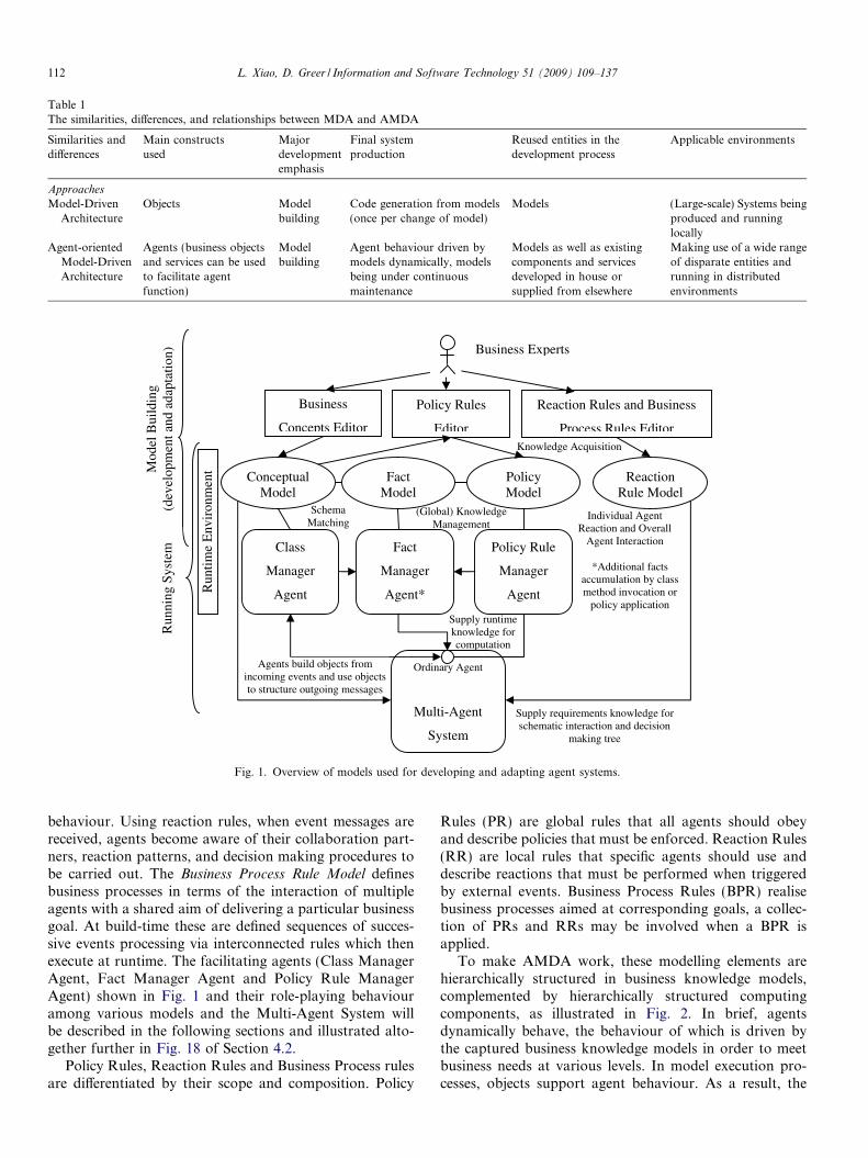
Table 1The similarities, differences, and relationships between MDA and AMDA
Similarities anddifferences
Main constructsused
Majordevelopmentemphasis
Final systemproduction
Reused entities in thedevelopment process
Applicable environments
Approaches
Model-DrivenArchitecture
Objects Modelbuilding
Code generation from models(once per change of model)
Models (Large-scale) Systems beingproduced and runninglocally
Agent-orientedModel-DrivenArchitecture
Agents (business objectsand services can be usedto facilitate agentfunction)
Modelbuilding
Agent behaviour driven bymodels dynamically, modelsbeing under continuousmaintenance
Models as well as existingcomponents and servicesdeveloped in house orsupplied from elsewhere
Making use of a wide rangeof disparate entities andrunning in distributedenvironments
Business
Concepts Editor
Policy Rules
Editor
Reaction Rules and Business
Process Rules Editor
ConceptualModel
FactModel
PolicyModel
ReactionRule Model
Ordinary Agent
Multi-Agent
System
Fact
Manager
Agent*
Policy Rule
Manager
Agent
Class
Manager
Agent
Run
ning
Sys
tem
Business Experts
Knowledge Acquisition
SchemaMatching
(Global) Knowledge Management
*Additional facts accumulation by class method invocation or
policy applicationSupply runtime knowledge for computation
Supply requirements knowledge for schematic interaction and decision
making tree
Run
time
Env
iron
men
t
Individual Agent Reaction and Overall
Agent Interaction
Agents build objects from incoming events and use objects to structure outgoing messages
Mod
el B
uild
ing
(dev
elop
men
t and
ada
ptat
ion)
Fig. 1. Overview of models used for developing and adapting agent systems.
112 L. Xiao, D. Greer / Information and Software Technology 51 (2009) 109–137
behaviour. Using reaction rules, when event messages arereceived, agents become aware of their collaboration part-ners, reaction patterns, and decision making procedures tobe carried out. The Business Process Rule Model definesbusiness processes in terms of the interaction of multipleagents with a shared aim of delivering a particular businessgoal. At build-time these are defined sequences of succes-sive events processing via interconnected rules which thenexecute at runtime. The facilitating agents (Class ManagerAgent, Fact Manager Agent and Policy Rule ManagerAgent) shown in Fig. 1 and their role-playing behaviouramong various models and the Multi-Agent System willbe described in the following sections and illustrated alto-gether further in Fig. 18 of Section 4.2.
Policy Rules, Reaction Rules and Business Process rulesare differentiated by their scope and composition. Policy
Rules (PR) are global rules that all agents should obeyand describe policies that must be enforced. Reaction Rules(RR) are local rules that specific agents should use anddescribe reactions that must be performed when triggeredby external events. Business Process Rules (BPR) realisebusiness processes aimed at corresponding goals, a collec-tion of PRs and RRs may be involved when a BPR isapplied.
To make AMDA work, these modelling elements arehierarchically structured in business knowledge models,complemented by hierarchically structured computingcomponents, as illustrated in Fig. 2. In brief, agentsdynamically behave, the behaviour of which is driven bythe captured business knowledge models in order to meetbusiness needs at various levels. In model execution pro-cesses, objects support agent behaviour. As a result, the

1..*
Business Process
Business Rule
Policy Rule
(Business Policy)
Reaction Rule
(Business Logic)
Business Concept
(Multiple agents)
(One agent)
(No agent)
defines terms (CM)
controls
1..* 1..*
Agent
Class /
Object
supports
CM FM
providesfacts (FM)
conforms to
Fig. 2. AAM components structure: two interactive hierarchies.
L. Xiao, D. Greer / Information and Software Technology 51 (2009) 109–137 113
interaction of the two hierarchies achieves the requiredbusiness goals. Collectively these hierarchies are termedthe Adaptive Agent Model (AAM) and it is this model thatforms the basis of our AMDA approach.
3.2. The meta-model
Fig. 3 shows a meta-model of the AAM approach, start-ing from Agent-oriented Requirements Modelling [56]. Inour approach, business processes realise business goals,agents collaborate towards business goals, and business
rules collectively support business goals through their con-trol of business processes. Agents, therefore, have theresponsibility of achieving the business goals. Individualagents collaborate by playing business roles, which are, inturn, constrained by business rules, which represent thefundamental functional requirements. Business functions
are distinguished from business rules. Business functionsrepresent stable blocks of requirements that are ownedand later implemented by the lower level business classes.Conversely, business rules represent volatile blocks of
Software
Agent
Human
Agent Business
Agent
Business
Role
Business
Class
collaborates_with
plays
participates_in
uses
owns
is_responsible_for
requirements container
Fig. 3. Meta-model for re
requirements that are attributed directly to the higher levelagents. It could be specified in business rules what, when,and how particular business functions of business classesare used by the agents.
The meta-model provides a perspective from a require-ments model as well as an execution model. The proposedAAM is aimed at an integrated development process. Inrequirements modelling, agents are used to organiserequirements from different domains. In the execution sys-tem, agents represent actors that act upon the domainswith respective domain knowledge. Usually, requirementsare structured by domains, in each of which a collectionof requirements with the same nature are grouped together.Naturally, one business domain can be delegated to oneagent, who has knowledge concerned with that domain.Agents represent actors that are responsible for the func-tion of their respective business domains. When the domainis required for different purposes, the corresponding agentresponds and plays several roles in order to realise severalaspects of domain functions, so fulfilling its responsibilities.Interactions among domains are delegated to message
Business
Process
Business
Goal
Business
Rule
Business
Function
controls
constrains
involves
realises
attributes_toindividual requirements
representation
high level requirements description
quirements modeling.

Case background: The specification comprisesthree main areas: Train Running and Performance,Infrastructure Management and Performance andCommon Communications, each of which is sub-divided into Business, Incident, and Execution
domains. These areas or domains are closely linked.For example, an infrastructure fault (InfrastructureManagement) may block the access to track andcause rescheduling of train services (Train Running).
Briefly, Train Running Business domain supportsthe principal service to customers, including deliveryof planned train paths and response to requests forfurther train paths. Relating to the domain, TrainOperators run train journeys on the network. TrainOperators are normally freight or passenger trainoperating companies. Each train journey is firstsupplied in the form of a plan, either as part of theworking timetable (planning), or as a result of arequest from a customer (re-planning). Railwayasset faults/incident will cause train service re-plan-ning as part of the case study. Although the runningof train services itself is not within the scope of thecase study of this thesis, it has been studied thor-oughly in [26].
The selected excerpt of the specification isconcerned about fault management of the railwaysystem. Involved domains are: Infrastructure Man-agement – Incident (abbreviated IMI), being respon-sible for passing of information about faults betweenthe system and contractors; Infrastructure Manage-ment – Execution (abbreviated IME), being respon-sible for granting of isolations; Train Running– Incident (abbreviated TRI), being responsible forrefinement and corrections of planned train jour-neys. External entities with respect to fault manage-ment are: Train Operators, who initiate train runningrequests, and have to be consulted when dealingwith perturbations, and Contractors, who carry outmaintenance.
114 L. Xiao, D. Greer / Information and Software Technology 51 (2009) 109–137
passing among respective agents. Such cross-domain inter-actions require collaboration of agents, and the collabora-tion pattern of agents is decided by the interactivity offunctions of the involved domains. Domain requirementsare assigned to agents in the form of rules or class func-tions. Later, this organisational structure is used forAgent-oriented design diagrams, reflecting relationshipsbetween agents and their responsibilities. Finally, the con-ceptual agents will be mapped to running agents. Principlemodelling elements in this scheme are given below.
3.2.1. Agent
Agents are conceptual units that organise requirementsin models and software units driven by the models to realiseassigned responsibilities. Agents interact with one other bypassing messages. Agents use knowledge in rules to processincoming messages and produce outgoing messages, con-tributing to goals and objectives they are expected to meet.
3.2.2. Rule
Rules are captured functional requirements that are con-figurable at runtime. Rules constitute externalised agentknowledge and inform agents their behaviour at runtime.Agents use rules to understand and respond to messages,make decisions and collaborate with each other. A collec-tion of rules compose and define agent interaction models.An agent chooses various rules to play various roles in var-ious interactions.
3.2.3. Class
Classes are traditional passive components. Classobjects respond to active agents when they are invoked,thus assisting in realising the behaviour of the runningagents. Such agent–class collaborations are defined in rules.
3.2.4. Message
A message is an object container passing betweenagents. Messages with objects encoded in them are knownby agents that create them and are expected by agents thatreceive them, if the related rules have been defined. It isalso defined in rules what objects are encoded at the send-ing side, and how they are decoded at the receiving side.The passing of a message indicates the sender has madeits contribution towards a business goal and now the recei-ver takes its responsibility to contribute to the same goal.
This sub-model is the core of the meta-model shown inFig. 3 and actually structures Agent, Rule and Class in ahierarchy [26]: (i) agents are used to model conceptualdomain units and are guided by collections of rules indomains; (ii) rules are used to capture requirements andguide agent behaviour and (iii) classes are employed byrules to support the function of agents. This provides a per-spective on AAM composition from an execution viewpointin contrast with the viewpoint of the AAM knowledge com-position, presented previously. Here, rules represent bothReaction Rules and Policy Rules which compose BusinessProcess Rules. Classes represent the implementation of
Business Concepts. The two viewpoints complement eachother and form the blueprint of AAM systems.
3.3. Case study
An actual British railway management system specifica-tion has been investigated as a case study. The system ismainly responsible for the running of the railway on a dailybasis, monitoring train running with regard to incidentsand ensuring the safety of the train services by conveyingissues to relevant parties for resolution. Being a very com-plex system, the specification document has more than 250pages and contains a large number of standardised form-based function descriptions.

Case terminology: The infrastructure of the railwaysystem consists of the assets necessary to run the trains.Their condition is a major constraint on train running.An infrastructure asset is any identifiable item of inter-est within the infrastructure. Examples of assets arepoints, bridges, or electrification equipment. An infra-structure asset may have a number of asset faults. Assetfaults may either cause an incidentor may be caused byan incident. Asset faults may also occur independentlyof an incident. Examples of incidents are accidentaldamage, spills or faults themselves. An incident maycause a track restriction. For example, a broken railmay cause a line blockage. The condition of an infra-structure asset may also cause a track restriction. Forexample, deterioration in track quality may cause atemporary speed restriction. Track restrictions includeisolations, temporary speed restrictions, line blockagesand reduced loading gauge. Under a contract or a var-iation to a contract with a contractor, infrastructureassets are maintained and asset faults are fixed.
Case description: An asset fault is either reportedto the system (Requirement: IMI-AcceptFaultReport)or detected directly by the system (Requirement: IMI-
NoticeFault). The handling of both cases is the same(Requirement: IMI-HandleFault). If the fault hasalready been cleared no further action is neededimmediately. Otherwise the system notifies the Con-tractor responsible for the fault and agrees a priorityfor fixing the fault. The fault may not require imme-diate attention and may have no immediate impact,in which case nothing further is done. However, ifthe fault is located at capital cities, it has impact and
needs to be fixed immediately. If the fault does havesome impact an incident is recorded. It may be neces-sary to put in place immediate track restrictions(Requirement: IME-ImposeSuddenRestrictions), andthis will involve changes to forecast train journeys(Requirement: TRI-RespondToIncident). Affectedtrain journeys are amended for re-scheduled servicesto the Train Operator. Those concerned may be noti-fied of the details (Requirement: CCI-NotifyIncident).As time passes or work progresses, further informa-tion may be received about the fault (Requirement:IMI-UpdateFaultInformation). This may result inchanges to the priority of the fault or imposition orremoval of track restrictions. A special case of thisis the final fixing of the fault, when the restrictions willbe removed.
L. Xiao, D. Greer / Information and Software Technology 51 (2009) 109–137 115
A large number of specific functional requirementstables have been documented for each domain. One ofthem, IMI-HandleFault, is given in Table 2, a focus ofthe case study. Formatting requirements in template tableslets requirements be expressed in a unified manner and
allows engineers to manage them easier and to find theirrelationship and missing pieces quicker.
3.4. Requirements Model: Goal decomposition
Goals must be identified and refined so that they can beturned into specifications of operational services and con-strains, assigning to agents as their responsibilities [23].Goals are usually explicitly stated in the user requirementsdocument, informing the purpose of the supporting busi-ness. A goal-decomposition technique is employed, similarto [57,58], starting from analysis of high level strategic con-cerns and ending up with the requirements specificationbroken down and low-level functional requirementsexposed and related.
However, the technique to be applied here has its owndistinction due to the fact that the developed business mod-els must be mapped from goals and shall be interpretable toagent software at runtime. Many approaches and tech-niques alike refine goals until they are assignable to singleagents and assign a goal to an agent only if the agent cancompletely realise the goal. For example, the assertion thata goal is realisable by an agent, as in [59], may be inter-preted as an agent finding a path from its initial state toreach the next state, as required by the goal, by means ofobserving its monitored variables and manipulating itscontrolled variables. Thus, a lack of monitor-ability orcontrollability is usually the cause of unrealisable goals.Refinement tactics that introduce intermediate goals oragents or objects may be used to solve this problem. Sucha goal-oriented RE strategy requires a one-to-one mappingof goal to agent, often related with formal refinement pat-tern and logic-based agent specification. In a business andIT context, however, it is probably not the best means forbusiness/software modelling and development, where theaim is producing executable agent software systems andturning goals into tangible business models and maintain-able agent knowledge. Moreover, in reality, many businessentities must cooperate towards the same objective. Thus,such a modelling practice does not naturally match to anoperational business model and cannot take full advantageof MAS development.
In our framework, organising functional requirementsin terms of their goals can build a hierarchal requirementsstructure, where those at the bottom support those at thetop. Top-level requirements are those most valued by thebusiness people and reflect the final business goals. Subor-dinate goals can be derived iteratively using a goal-decom-position technique down to the lowest level goals, whichmap to individual functional requirements. The top levelbusiness goal, in the first place, can be decomposed intoa set of intermediate goals. The decomposed goals, calledsub-goals to distinguish them from the original goals, canbe further decomposed into still smaller sub-goals. In theprocess they are considered just like the ordinary goals inthe subsequent decomposition process. Finally, when thebusiness goal is decomposed to the smallest granularity,

Table 2Functional requirements table IMI-HandleFault
Domain IMIIdentifier HandleFaultDescription To maintain information about faults so that they can be fixed in a way which minimises the overall impact on the businessCause A fault becomes known to the Production Function, either from people reporting information about a fault (IMI-
AcceptFaultReport), or directly from the infrastructure asset, via infrastructure monitoring equipment or from failure to operatewhen commanded (IMI-NoticeFault)
Information used Information about infrastructure assets and their contractsInformation about train journeysto assess the impact of the fault
Outputs Fault information to contractors
Required effect The fault is recordedUnless the fault has already been cleared, the appropriate contractor is identified and agreement is reached about a priority for fixingthe fault.If the fault is associated with an existing incident, then that is recorded; otherwise, if it has some impact then a new incident isestablished with the fault as its cause.If necessary, track restrictionsare put in place. If so there is an impact on the train service handled by TRI-RespondToIncident
Anyone affected by the fault is notified (CCI-NotifyIncident)
116 L. Xiao, D. Greer / Information and Software Technology 51 (2009) 109–137
the process terminates and all the leaf nodes are presentedas operational functional requirements. This provides ameans for incremental elicitation of requirements. Onlywhen all the leaf nodes existing as requirements units pre-sented in the specification and the top nodes being fullysupported by the bottom ones, can the business goals beguaranteed to be represented completely in the require-ments documentation. Since a business process realises abusiness goal, it is possible to dedicate a business processto one functional requirement, mapping to a sub-goal ina leaf node or, alternatively and more likely, a combinationof these sub-goals aggregated in an intermediate node.
Whatever the case, it is not required here that one agentrealises one goal as in many other approaches discussedabove. Rather, it is more often the case that many agentsparticipate in a business process, only through the collabo-ration of which the corresponding goal can be realised. Therationale for this is that, although it is possible to assign asingle agent to an atomic requirement, the resulting archi-tecture is probably not that natural or straightforwardwhen realised in a business software system. More appro-priately business processes are the direct representativesthat organise many agents, whose functions and coopera-tion are towards the same goal. This is one of the noveltiesof our goal-decomposition and its distinctions from othersuch approaches in the Requirements Engineering area.
It is worth noting that, although ‘‘AND” and ‘‘OR”
relationships among goals are both widely employed ingoal-decomposition techniques, we omit the use of ‘‘OR”due to our motivation in using goals in requirements anal-ysis. In other approaches, ‘‘OR” can facilitate the exploita-tion of alternative goal composition relationships. Inrequirements engineering, goals are usually used forrequirements acquisition or for developing requirementsspecifications. In the process of elaborating a goal hierar-chy, the requirements of a stakeholder are revealed, andstakeholders become more aware of potential alternativesfor meeting their substantive goals [60]. As such, thegoal-oriented requirements engineering is applied in the
early requirements analysis phase to gain better under-standing of potential low level requirements. In our case,however, we start from a well understood and fully docu-mented requirements specification shown in Section 3.3,where all processes, rules, concepts involved in the systemhave already been made clear though embedded implicitlyin the case description of the requirements specification.The requirements specification has been developed andagreed upon between stakeholders and developer teams.Nevertheless, the goal-decomposition approach is in useby our approach, for an opposite purpose: not for elicitingrefined requirements, but for tracing back to the originaltop-level goal, thus ensuring requirements completenessand establishing the relationships among low-levelrequirements.
In the case where alternative goals exist as valid possibil-ities in the requirements specification this can be dealt withby separate rules (discussion of which follow) given differ-ing priorities, the dominant rule having the highest priorityattribute.
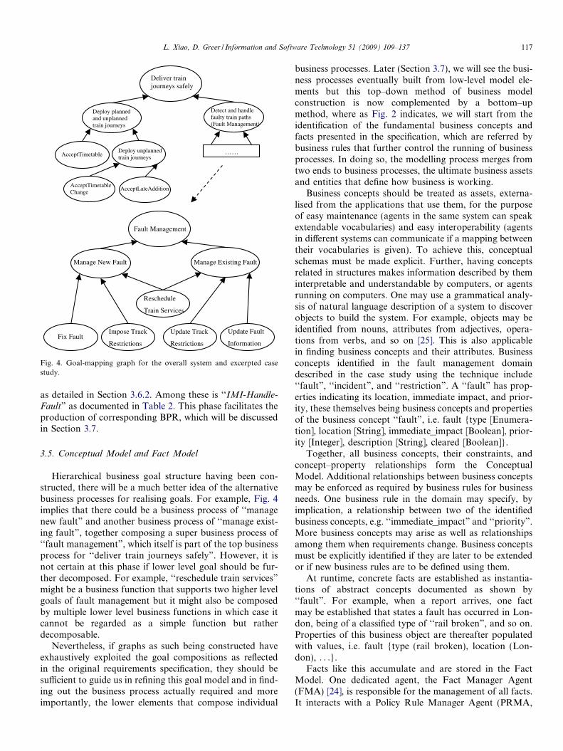
Fig. 4 demonstrates the decomposition process for thecase study. The top business goal of ‘‘deliver train journeyssafely” as emphasised in the specification, in the first place,can be decomposed into ‘‘deploy planned and unplannedtrain journeys” and ‘‘detect and handle faulty train paths”.The former sub-goal can then be decomposed according tothe nature of the train journeys. The latter one, being itselfthe top-level goal under our study, can be decomposed into‘‘manage new fault” and ‘‘manage existing fault”, since theprocesses of handling faults differs in different phases of thelife cycle of faults. A fault is sent to be fixed and trackrestrictions are imposed if it is a new incoming one. Faultinformation gets updated and the corresponding trackrestrictions get updated as well (in some case removed ifthe fault has been fixed). In both cases train services arerescheduled. Such smallest granularity produced after thedecomposition process are actually documented as func-tional requirements tables in the specification of our casestudy, which will be transformed into agent Reaction Rules
AcceptTimetable Deploy unplanned train journeys
Deploy planned and unplanned train journeys
AcceptTimetableChange
AcceptLateAddition
Detect and handle faulty train paths (Fault Management)
Deliver train journeys safely
……
Fix Fault
Manage New Fault
Fault Management
Manage Existing Fault
Impose Track
Restrictions
Reschedule
Train Services
Update Track
Restrictions
Update Fault
Information
Fig. 4. Goal-mapping graph for the overall system and excerpted casestudy.
L. Xiao, D. Greer / Information and Software Technology 51 (2009) 109–137 117
as detailed in Section 3.6.2. Among these is ‘‘IMI-Handle-
Fault” as documented in Table 2. This phase facilitates theproduction of corresponding BPR, which will be discussedin Section 3.7.
3.5. Conceptual Model and Fact Model
Hierarchical business goal structure having been con-structed, there will be a much better idea of the alternativebusiness processes for realising goals. For example, Fig. 4implies that there could be a business process of ‘‘managenew fault” and another business process of ‘‘manage exist-ing fault”, together composing a super business process of‘‘fault management”, which itself is part of the top businessprocess for ‘‘deliver train journeys safely”. However, it isnot certain at this phase if lower level goal should be fur-ther decomposed. For example, ‘‘reschedule train services”
might be a business function that supports two higher levelgoals of fault management but it might also be composedby multiple lower level business functions in which case itcannot be regarded as a simple function but ratherdecomposable.
Nevertheless, if graphs as such being constructed haveexhaustively exploited the goal compositions as reflectedin the original requirements specification, they should besufficient to guide us in refining this goal model and in find-ing out the business process actually required and moreimportantly, the lower elements that compose individual
business processes. Later (Section 3.7), we will see the busi-ness processes eventually built from low-level model ele-ments but this top–down method of business modelconstruction is now complemented by a bottom–upmethod, where as Fig. 2 indicates, we will start from theidentification of the fundamental business concepts andfacts presented in the specification, which are referred bybusiness rules that further control the running of businessprocesses. In doing so, the modelling process merges fromtwo ends to business processes, the ultimate business assetsand entities that define how business is working.
Business concepts should be treated as assets, externa-lised from the applications that use them, for the purposeof easy maintenance (agents in the same system can speakextendable vocabularies) and easy interoperability (agentsin different systems can communicate if a mapping betweentheir vocabularies is given). To achieve this, conceptualschemas must be made explicit. Further, having conceptsrelated in structures makes information described by theminterpretable and understandable by computers, or agentsrunning on computers. One may use a grammatical analy-sis of natural language description of a system to discoverobjects to build the system. For example, objects may beidentified from nouns, attributes from adjectives, opera-tions from verbs, and so on [25]. This is also applicablein finding business concepts and their attributes. Businessconcepts identified in the fault management domaindescribed in the case study using the technique include‘‘fault”, ‘‘incident”, and ‘‘restriction”. A ‘‘fault” has prop-erties indicating its location, immediate impact, and prior-ity, these themselves being business concepts and propertiesof the business concept ‘‘fault”, i.e. fault {type [Enumera-tion], location [String], immediate_impact [Boolean], prior-ity [Integer], description [String], cleared [Boolean]}.
Together, all business concepts, their constraints, andconcept–property relationships form the ConceptualModel. Additional relationships between business conceptsmay be enforced as required by business rules for businessneeds. One business rule in the domain may specify, byimplication, a relationship between two of the identifiedbusiness concepts, e.g. ‘‘immediate_impact” and ‘‘priority”.More business concepts may arise as well as relationshipsamong them when requirements change. Business conceptsmust be explicitly identified if they are later to be extendedor if new business rules are to be defined using them.
At runtime, concrete facts are established as instantia-tions of abstract concepts documented as shown by‘‘fault”. For example, when a report arrives, one factmay be established that states a fault has occurred in Lon-don, being of a classified type of ‘‘rail broken”, and so on.Properties of this business object are thereafter populatedwith values, i.e. fault {type (rail broken), location (Lon-don), . . .}.
Facts like this accumulate and are stored in the FactModel. One dedicated agent, the Fact Manager Agent(FMA) [24], is responsible for the management of all facts.It interacts with a Policy Rule Manager Agent (PRMA,

118 L. Xiao, D. Greer / Information and Software Technology 51 (2009) 109–137
detailed in Section 3.6.1) to add new deduced facts after theapplication of Policy Rules, and can acknowledge allagents the facts available to the system. For example, onepolicy may say that a fault occurs at London will have ahigh priority of 10 and immediate impact. The Fact Modelwill be updated correspondingly, i.e. fault {type (rail bro-ken), location (London), immediate_impact (True), prior-ity (10), . . .}.
The concept of ‘‘fault” and its related properties are rep-resented in XML as shown in Fig. 5. This concept will bereferred to by the PR shown in Fig. 6 and RR shown inFig. 12. A corresponding business class ‘‘Fault” has laterbeen implemented for agents to operate upon. Businessobjects can be instantiated from the class. These can beencoded in agent messages for their communication,announcing among themselves the occurrence of faultsand requesting their repair. This lets FMA establish factsthat will be known by agents. New facts are accumulatedand invalid ones demolished dynamically at runtime. Busi-ness models are updated dynamically and reflected in agentknowledge.
The use of Conceptual and Fact Models is supple-mented by a lower layer class facility which enables theuse of existing OO infrastructure to represent and infer fur-ther knowledge. The facility is based on an agent–classhierarchy for Agent-oriented modelling and development[26], where dynamic agents invoke static class methods asrequired. At runtime, established facts are mapped to busi-ness objects instantiated from business classes, the schemasof which are as defined in the Conceptual Model. Methodsdefined on the business objects are invoked for the manip-
- <concept> <name> fault </name> - <properties> <property> type </property> <property> location </property <property> immediate_impact </ <property> priority </property <property> description </prope <property> cleared </property>
<!-- … more properties … -->
<properties> </concept>
Fig. 5. Business concept ‘‘fault” rep
Rule1.If fault is located at the capital citThen it has “immediate impact” --------------------------------------- <policy> <id>100</id> <condition> fault.location == “London” OR “E </condition> <action> fault.immediate_impact = true </action> <priority>5</priority> </policy>
Fig. 6. Policy Rule representation on
ulation of facts as per the business rules. This leads to theavailability of additional knowledge, supporting agents intheir reasoning and behaviour. Reusable class librariesand exchangeable class methods may be used. It is up tothe flexibly defined business rules that specific class meth-ods are selected and determined to be invoked in variousconditions to achieve dynamic effect.
3.6. Business Rule Model
Business rules constrain and connect concepts in theConceptual Model and describe semantic relationshipsamong them. These rules are stated in machine understand-able form but also allow human comprehension and edi-tion. Reactive Rules (RRs) are rules about processes thatare in reaction to some events. They constrain individualagents’ behaviour based on conditions and available busi-ness objects. Policy Rules (PRs) are rules concerning busi-ness policies. They constrain global relationship amongbusiness concepts that all agents must respect when theyuse them. Underpinned by the Conceptual Model and theFact Model, both contain meta-data knowledge and theyare applied by individual agents at various execution pointsof business processes, which involve multiple agents. Theadvantages of externalisation of agent behaviour in busi-ness rules are described in [44,45].
3.6.1. Policy Rule
The justification for using business rules is that they pro-vide a means for implementing business policy [28]. Busi-ness policies, naturally, change over time and thus
>property>>rty>
resentation for the case study.
ies
-------
dinburgh” OR “Cardiff” OR “Belfast”
fault impact for the case study.

L. Xiao, D. Greer / Information and Software Technology 51 (2009) 109–137 119
externalisation of them as executable rules is desirable. Itcould be conceived that a Policy Rule (PR) captures a con-straint of invariant type, while a Reaction Rule (RR) cap-tures pre-condition and post-condition constraints.
Policy Rules are normally implicit and embedded inrequirements specifications. The underlined sentence inthe case study descriptions reads: if the fault is located at
capital cities, it has impact and needs to be fixed immedi-
ately. Such rules must be made explicit, as well as repre-sented in models. Otherwise, the embedment of them incode increases the maintenance burden.
Taking the above PR as an example, it says faults in thefault management system must be handled in accordanceto the nature of the emergency. This category of rules isdefined for classification of business concepts. Businessconcepts are sometimes required to be classified and treateddifferently because of their different nature/attributes.Fig. 6 shows a description of the rule and its XML repre-sentation, stating that any fault found at capital cities hasimmediate impact, and so it possibly needs to be handleddifferently from faults of no immediate impact.
In the knowledge of Rule1, the Policy Rule ManagerAgent (PRMA) [26] would update the Fact Model throughits interaction with the Fact Manager Agent (FMA) at run-time. Suppose a ‘‘fault” is informed to the system. A fact isthen established in the Fact Model with its ‘‘immedi-ate_impact” initially unknown but ‘‘location” known asLondon. It is through the PRMA’s evaluation of the latterproperty using the PR currently set by the business peoplethat the Fact Model is updated, so that the former property‘‘immediate_impact” of the ‘‘fault” is set as ‘‘true”.
Another category of PR is defined on the relationship of(classified) business concepts or their properties, triggeringthe formation of a chain of PRs. Rule2 (Fig. 7) uses theterm ‘‘immediate impact” as its condition and the sameterm is defined in Rule1 as its consequent action. The exe-cution of the Rule1 triggers the execution of the Rule2 anda PR chain is thus formed. It is easy to infer that a faultlocated at capital cities has a high priority, as a PR chainis formed. In an iterative means, new facts are progressivelyknown and other PRs may come into play, leading to addi-tional facts being established, based on existing facts. Theprocess proceeds until no more PR conditions are satisfied.Such relationships as concept reference, logical inference,and collaborations among PR contribute to the establish-ment of a PR chain. Other PRs may contain computationalformulas that can be used to calculate the concrete valuesof certain elements at runtime.
A third category of PR is defined on the different systembehaviour that can be expected depending on the (classi-fied) business concepts/properties. Rule3 and Rule4
Rule2.If fault has “immediate impact” Then it has a high priority
Fig. 7. Policy Rule of the second
(Fig. 8) are actually used in combination with and to con-tribute to a RR (detailed in Section 3.6.2), distinguishingdifferent means for fault handling in different conditions,as a result of different policies.
PRs are built from the requirements elicitation, analysis,decomposition, and reconstruction, providing models withtraceability from their origin, so assisting maintainability.Systems using PRs can be implemented independentlyfrom any particular technology. Tools [6,29] have beendeveloped to facilitate viewing, addition and edition ofPRs as well as RRs. The combinational use of PR andRR, working in BPR towards a common goal is describedin Section 4.
3.6.2. Reaction Rule
The overall architecture of a software system is impor-tant to the efficiency and effectiveness of maintaining it[30]. The AAM has an event-driven architecture, its agentsbeing reactive to events in the knowledge of ReactionRules. Event-oriented decomposition, based on events thatthe system must handle, is a design strategy that enablesmodular architecture, easy design, independent unit devel-opment, and eventually effective maintenance [35]. Events,when becoming part of our models, can drive agent behav-iour, according to actions and conditions related with theevents described in the models. Thus, agents react to eventsand through sequences of successive events, business pro-cesses are formed and executed logically. Naturally, notall future events are predictable and so enabling the evolu-tion of agent reactivity locally and business process interac-tivity globally is essential. This evolution is possible sinceReaction Rules are continuously editable and variation ofevents can dynamically drive agents to choose variousexternal interaction patterns or internal event processingprocedures.
Consisting of events, RRs define agreements that arebound between agents for their interactions, constrainingwhat and how agents should perform in a reactive manner.Driven by events, agents use RRs to make business deci-sions using condition and action pairs. When an event mes-sage is received by an agent, business objects are decodedfrom it and facts become known to the recipient. Torespond to this new knowledge, the agent may make a deci-sion and perform an action, possibly produce event mes-sages to other agents in order to accomplish a businessprocess.
Since different decisions can be made by individualagents in different situations upon receiving dynamicallygenerated events, individual agent reaction and multi-agentinteraction can be adaptive according to configurable rulemodels.
category from the case study.

Rule3.If fault has no “immediate impact” Then IMI-HandleFault does nothing
Rule4.If fault has “immediate impact”
Then IMI-HandleFault establishes a new incident associated with the fault AND request IME to place track restrictions
Fig. 8. Policy Rule of the third category from the case study.
120 L. Xiao, D. Greer / Information and Software Technology 51 (2009) 109–137
Fig. 9 shows the Reaction Rule Model and how an agentprocesses a RR using the following steps.
1. Check event – find out if the rule is applicable to dealwith the perceived event.
2. Do processing – decode the incoming message, constructbusiness objects to be used in later phases.
3. Check condition – find out if the (condition ci) issatisfied.
4. Take an action – if ci is satisfied, then do the correspond-ing (action ai) that is related with (condition i) as definedby the rule. Then send a result message to another agent(possibly the triggering one). If ci is not satisfied, then goback to Step 3 and check the condition ci+1.
5. Update beliefs – according to the information obtainedfrom the message just received, the knowledge of theagent to the outside world is updated.
Reaction Rules, as specified here, make agent anabstraction over object. An agent uses a dedicated rulefor a specific task and, in turn, a rule uses business classesto complete it. What and how classes are to be invoked canbe specified in rules. The configurability of rule modelsaccommodates mutable requirements including collabora-tion partners, events processing, reaction selection so even-tually driving changing system behaviour.
In the case study specification, a set of functions arerequired for managing faults. Three functions of specialconcern are reconstructed in Fig. 10. They constrain busi-ness domains to their expected function in different aspects.IMI-HandleFault, for example, has its prefix indicating thatit belongs to the IMI business domain, and constrains IMIin its handling of faults in reactions. This function is docu-
Action: perform actions coupled with the satisfied conditions, this results in outgoing messages
Event: incoming request messages
Outgoing messages
c1
c2
cn
Reaction Rule
Check Rule Condition
(c1, c2, … , cn)
e
IncomingMessage
a2
a1
an
Processing: process the incoming message
Belief: the agent that executes the rule updates its belief using the informationreceived in the incoming message
Fig. 9. Reaction Rule Model.
mented in a functional requirements table in Table 2. RRsspecify domain functions as well as respective constraintswith behavioural semantics.
Agent IMI processes its RR IMI-HandleFaultin themanner shown in Fig. 11.
A RR acts like a contract between agents. For example,IMI-HandleFault, as a fault handling RR in this fault man-agement domain, will only respond if an event messagewith a pre-defined information structure representing anasset ‘‘fault” being received. In addition, it promises pre-defined information structures sent to the pre-agreed part-ners as defined by the RR. The XML specification of theRR is shown in Fig. 12. A guideline for transforming func-tional requirement tables as shown in Table 2 to RR struc-tures and then XML specifications is provided in [26].
XML-based rules provide precise definitions of agentbehaviours to the Design Models, something UML dia-grams lack [8]. In general, each agent reacts to the receiptof a message by executing a rule using the following processshown in Fig. 13.
RRs can play the role of a connector [32,33] or a contract[4], as they have the capability of evolving software architec-ture via rule configuration. Compositional parts of rules sep-arate computation from coordination. heventi and hactioniparts serve as interfaces, connecting one agent with its coor-dinated agents through incoming or outgoing messages andso model architectural interfaces. The hprocessingi partserves internal computation. This part captures the invoca-tion of existing components and so models internal compu-tational structure. This separation of concerns makessoftware evolution easier. Agent collaboration patternsand the main processing component can be maintained indi-vidually. From this perspective, the heventi section modelsthe pre-condition of agent behaviour, the hactioni sectionmodels the post-condition of agent behaviour, the hcondi-tioni section models the guard and controls the rule execu-tion path. At runtime, agents check these mutableconstraints separately and dynamically.
It should be noted that class methods such as‘‘cleared()” and ‘‘immeImpact()” may arise from the needof function facility of the corresponding classes. Thesecan be invoked to facilitate agents to operate, judging con-ditions and performing actions. Other methods maydirectly originate from functional requirements tables,which are sub-requirements of others and support commonfunctions rather than specific business tasks. One exampleis that the ‘‘ValidateTrainPlan” requirement is a sub-requirement of the ‘‘AcceptLateAddition” requirement

IMI-HandleFault is informed by IMI-AcceptFaultReport or IMI-NoticeFault about an asset fault,
IF the fault has been cleared THEN DO_NOTHING,
ELSE
Inform the responsible Contractor about the fault with an agreed priority,
IF the fault has no immediate impact THEN DO_NOTHING,
ELSE
Create an incident related with the fault AND
Create and put in place track restrictions using IME-ImposeSuddenRestrictions AND
Inform concerned parties using CCI-NotifyIncident.
IMI-UpdateFaultInformation is informed about further information of a known fault,
Update fault information AND
Inform the responsible Contractor about the re-prioritised fault AND
Update (or remove) track restrictions using IME-UpdateRestrictions (or IME-
RemoveRestrictions, respectively) AND
Inform concerned parties about the update using CCI-UpdateIncidentInformation.
TRI-RespondToIncident is informed by IME-ImposeSuddenRestrictions or IME-
UpdateRestrictions (or IME-RemoveRestrictions) about the track restrictions and incidents, which
have impact on the delivery of the train services,
Create amended train journeys for re-scheduled services and inform Train Operator.
Fig. 10. Reconstructed specification for the case study.
Step1: Receive fault report message from “AcceptFaultReport” or “NoticeFault” from the same
agent.
Step2: Construct a “Fault” and an “Asset” object using the information contained in the message.
Step3&4 {condition, action} couplet1: If the created “Fault” object is evaluated by the “cleared()”
method as FALSE (Condition2), Then send a message with the created “Fault” to “FixFault”
owned by Contractor agent (Action2), and
Step3&4 {condition, action} couplet2: If the created “Fault” object is evaluated by the
“immeImpact()” method as TRUE (Condition2.2), Then send a message with the created “Asset”
to “ImposeSuddenRestrictions” owned by IME agent (Action2.2).
Step5: Add the belief that a fault occurs at this moment with a potential incident related with it.
Fig. 11. Brief steps of RR IMI-HandleFault processing by agent IMI.
L. Xiao, D. Greer / Information and Software Technology 51 (2009) 109–137 121
[26]. The former requirement becomes a class function thathelps the later requirement which becomes a RR to vali-date additionally required train journeys. Since ‘‘Accept-LateAddition” is a particular business task assignable toa single agent responsible for that task, it needs to beowned by the agent as a RR. Also because ‘‘ValidateTrain-Plan” supports many RRs to function and not assignable
to any particular responsible agent, it needs to be sharedby many agents as a class method. Such a distinction differ-entiates business rules and business functions as describedin the meta-model section.
The interaction of the example RR with other RRs andbusiness classes can be documented in two design models,the Structural Model and the Behavioural Model shown

Fig. 12. Reaction Rule IMI-HandleFault specification for the case study.
122 L. Xiao, D. Greer / Information and Software Technology 51 (2009) 109–137
in Figs. 14 and 15, respectively, the basis for building Busi-ness Process Rules described in the next section.
In a Structural Model, each rounded cornered box rep-resents an agent and is divided into three compartments.The top compartment holds the name of the agent, themiddle compartment holds the classes managed by theagent along with their instantiation, and the bottom com-partment holds the rules that govern the behaviours ofthe agent. This regards agents as superior to classes, justlike classes are regarded as superior to attributes in a ClassDiagram. Agents are connected by ‘‘collaborate” lines, the
collaboration among which is through one agent producesa message using one of its rules and another agent pro-cesses it using one of its rules. In the scenario, IMI collab-orates with Contractor and IME using the ruleHandleFault to fulfil its goal of handling fault. ‘‘Asset”and ‘‘Fault” are the business classes IMI uses to produceaction messages for that collaboration. A message contain-ing fault information will be sent to Contractor. As the def-inition of its rule FixFault indicates, it is its responsibilityto process that message to fix the fault using a ‘‘Fault”business class. Likewise, IME uses its rule ImposeS-

1. Get a list of its managed rules that are documented in a XML rules repository, according to the
<owner-agent> section.
2. Filter these rules and retain those which are applicable to the current business process according
to the <business-process> section.
3. Get the rule currently has the highest priority according to the <priority> section.
4. Check the applicability of this selected rule, that is, if the <event> section matches the event that
has occurred. In other words, check if the agent that triggers the received message is the same as
that given in the <from> section of the <message> in <event>, and the received message format is
also as specified in the <message>. If that is not the case, go to Step 9.
5. Decode the message received and build business objects from it following the <processing>
instructions. Constructor methods of existing classes will be involved. Global variables declared in
the <global-variable> section will be used to save the results.
6. Check if the current condition specified in the rule is satisfied according to the <condition>
section. Constructed business objects will be involved, and their methods will be invoked upon to
assist the rule to function. If the condition is not satisfied and it is not the last condition, check the
next condition, otherwise go to Step 9.
7. Execute the corresponding <action> section. This involves encoding constructed business
objects that refer to <global-variable> into a message. Send the message to the agent which is
specified in the <to> section of the <message> in <action>.
8. Analyse the business object which has been decoded from the message received and update the
agent’s beliefs with the new information available.
9. Remove this selected rule from the rules set obtained in Step 2 and go to Step 3.
10. Wait for the next event.
Fig. 13. Reaction Rule in XML processing procedures.
collaborate
Faultinformation
Contractor
obj: Fault
……
FixFault (obj)
IMI
obj: Asset
obj: Fault
HandleFault (obj)
Fault
Fault (reportMsg:Report) cleared(): Boolean immeImpact(): Boolean
Handle Fault
IME
obj: Asset
……
ImposeSuddenRestrictions (obj)
collaborate
Assetinformation
Fig. 14. Structural Model for the case study centred on IMI-HandleFault.
L. Xiao, D. Greer / Information and Software Technology 51 (2009) 109–137 123

Fix Fault Handle Fault
IMI
1: Fault information
2:
Handle Fault
AcceptFaultReport
NoticeFault Contractor
ImposeSudden Restrictions
IMEcleared ()
Fault (reportMsg)
immeImpact
4: Fault information & request for fixing fault (Action2)
Falsecleared?
3: Check its clearance
(Condition2)
M
Create a new fault & asset object
4: Asset information & request for imposing restrictions (Action2.2)
Trueimpact?
3: Check its impact
(Condition2.2)
M
Fig. 15. Behavioural Model for the case study centred on IMI-HandleFault.
124 L. Xiao, D. Greer / Information and Software Technology 51 (2009) 109–137
uddenRestrictions to process a message containing assetinformation to impose restrictions at a correspondingasset. The collaboration of the three agents towards a com-mon goal of handling faults is captured in the RR models.
The Behavioural Model shows the same but from a per-spective of capturing behavioural scenarios. It comple-ments the Structural Model just like in the OO worldClass Diagrams are complemented by Sequence Diagrams.As demonstrated in the design models, the use of businessclass components and the collaboration details amongagents are in models and reconfigurable with rules. TheXML definitions of the RRs are associated with the ele-ments in the design models. This provides the agent ameans to carry out computation using the models, and atthe same time offers business people visual presentationand a method to modify models. The model configurationinformation is obtained by agents at runtime to ensure thedeployment of the most up-to-date requirements. A busi-ness rule model architecture for agents is hence achieved.
The Reaction Rule language plays a similar role to otherinterface languages like the OMG’s Interface DefinitionLanguage (IDL) [34]. IDL defines the interface onlythrough which client objects can communicate with serverobjects in a distributed environment. This facilitates theencapsulation of the internal structure of the server objects.An interface definition specifies operations to be per-formed, inputs and outputs, allowing clients and serversto encode and decode values for their travel over the net-work, regardless of their platform, operating system, pro-
gramming language, and so on [34]. The rule interfacehere specifies messages that can be passed between agentsand this sets a contract through which the interaction pat-tern between communication components related by it canbe enforced. A client agent is not aware of how a serveragent processes its action message. However, that messageis the event message to the server agent, so that a rule of ittells it how to react. This ensures the encapsulation of agentfunctions, and the message passing over network is alsotechnology-independent.
3.7. Business Process Rule Model
Given the RR structure described in the previous sec-tions, each RR has an internal processing component,and an external interface of event message receiving andaction message sending, through which agents interact.The execution of collections of RRs following event mes-sage flow sequentially and conditionally forms businessprocesses, combining inter-related Behavioural Modelsbuilt upon Reaction Rule Models, and thus forming theblueprint of the system. These interconnected models con-strain business processes and form higher level rules,termed Business Process Rule (BPR). Thus, one RR isabout how a given task is to be performed following a pro-cess, being a goal internal to one agent, while a given BPRis about how one business is achieved by a process com-posed of interconnected RRs. A BPR thus delivers, a goalshared by many agents.

L. Xiao, D. Greer / Information and Software Technology 51 (2009) 109–137 125
IMI-HandleFault is activated by the business process formanaging new faults. It is one of a group of RRs that com-prise the corresponding BPR, called ‘‘Manage New Fault”.This BPR is shown in Fig. 16, with only the default condi-tions considered and assumed to be true for simplification.This is one of the two sub-goals of a higher level goal‘‘Fault Management”, as a result of the goal decomposi-tion shown in Fig. 4. Two aspects are involved towardsthat goal: (i) new faults are reported and then handledand (ii) existing faults are handled in an alternative wayor eventually removed as information about them isupdated. The illustrated BPR extends the two Design Mod-els shown in the previous section, connecting all relatedagents and their RRs that collaborate towards the sharedgoal.
The agent IMI initialises the above BPR using either ofits two RR: ‘‘IMI-AcceptFaultReport” or ‘‘IMI-Notice-
Fault”, in the interest of solving newly detected faults.The agents that finalise the BPR are Contractor and TrainOperator, the completion of whose functions fulfils thegoal of managing new faults. Fig. 17 shows the BPR‘‘Manage New Fault” in XML, expecting a new fault asinput/cause/pre-condition, and ‘‘fault fixed” and ‘‘trainservice re-scheduled” as output/effect/post-condition.
In the XML representation of BPR, Initial Agents (IAs)are referred to by those that initiate the BPR and FinalAgents (FAs) are referred to by those that finalise BPR.IAs act spontaneously without request by other agentsand FAs complete the BPR and request no further actionof other agents. Intermediate agents participate in BPRbetween the activities of IAs and FAs during the executionof BPR. For every input from the IAs, output can beexpected from the FAs, indicating that the goal of the busi-ness process has been accomplished. An IA is seen as theinitiator actor and a FA could be a benefactor in use caseterminology. As long as the input, output and goal of aBPR are all met, it is a black box and there is no need tobe concerned about the selection/substitution of intermedi-
Handle Fault
NoticeFault
Impose SuddenRestriction
AcceptFaultReport
IMI
Trackrestrictionrequest
IME
Trackrestrictions and incidents
Train Operator
Amended train journeys
FixFault
Fault locations
RespondToIncident
TRI
AcceptTimetable Change
Contractor
Fig. 16. Business Process Rule ‘‘Manage New Fault” for the case study.
ate agents participating in the BPR, class invocation anddecision making in individual agents or policy application.The publication of BPRs to external systems allows theinvocation of them as services and so enablesinteroperability.
The rule hierarchy of Business Process Rule – ReactionRule – Policy Rule has been established. A BPR is formedby the execution of sequenced subordinate RR units, car-ried out by agents as primitive activities. In the course ofeach RR execution, PR chains are further applied in sup-port of RRs for decision making.
Both BPRs and use cases can be structured according togoals. During requirements analysis, responsibilities can beassigned to agents (in BPRs) or actors (in use cases),through the collaboration of which goals can be achieved.But BPRs have several advantages over use cases. A usecase will fire business rules to constrain its process, if theyare relevant in that use case context. BPRs act in a similarway as an integration unit of RRs. However, once a busi-ness rule is changed, all use cases that use the rule have tobe changed, manually and individually. In contrast, BPRsare dynamically composed by RRs at runtime, and so suchchanges are accommodated automatically. Related to this,another important distinction is that BPRs can be used toautomate the later development phases and remain re-usable, rather than lose their value, like use cases typicallydo, when the modelling is completed. The insufficientsemantics of use cases is even a barrier in its support formodel refinement [15]. Moreover, BPRs are also anenhanced form of specification. The hierarchical structureof BPR-RR-PR eases the later mapping to agent knowl-edge in respect to architectural interaction, individual reac-tion process, and global policy. This is in contrast with usecases, where objects and their relationships are difficult todirectly map to [35]. Finally, such a hierarchical rule struc-ture used in AAM allows agents to automatically interpretthe required knowledge from the configurable rule models,as opposed to the situation where object structure, methodinvocation, and interaction are all fixed after use case mod-els are built and development is completed.
4. Model configuration and execution
We have presented business models, organised in thehierarchical levels of business processes, business rules,and business concepts, represented both in natural lan-guage and in XML. The former is business experts-orientedwhile the latter is Agent-oriented. Both are interchangeablevia supporting tools [6,26]. Therefore, once businessknowledge is configured by business people in their ownlanguage, the changed constructs can be transformed bythe tools to corresponding XML portions that are analysa-ble and executable by software agents. For example, a busi-ness concept of ‘‘fault” may be required with the schemagiven in Section 3.5 and the tool receives the field content,as filled in by the business people of this particular conceptand puts this into the business model repository using

- <process> <name>Manage New Fault</name> <goal>a new fault is managed</goal> - <IAs> <IA>IMI</IA> </IAs> - <FAs> <FA>Contractor</FA> <FA>Train Operator</FA> </FAs> <cause>a new fault is reported</cause> - <effects> <effect> A Contractor will fix the fault </effect> <effect> Train Operator will re-schedule train services </effect> </effects> </process>
Fig. 17. XML representation of the BPR ‘‘Manage New Fault”.
126 L. Xiao, D. Greer / Information and Software Technology 51 (2009) 109–137
XML (as shown in Fig. 5), ready for parsing by agents.When business people have their business needs changed,say, the addition of properties, the reconfiguration of thebusiness concepts is via the same tool and this is reflectedin the business models and the knowledge of the runningagents immediately. Similarly, business rules and businessprocesses can be described in a constrained natural lan-guage manner by business people to the supporting toolsand corresponding XML representations formulated sothat agents can parse and execute them for action, reaction,and interaction purposes. This includes the dragging anddropping of model elements such as agents, rules and mes-sages provided by the tool and business processes can beconstructed visually (as shown in Figs. 15 and 16), corre-sponding XML being generated. Both the people-friendlybusiness models and the agent-friendly XML models areemployed and complement each other. They are equivalentsemantically but facilitate easy configuration by people andimmediate execution by agents.
To demonstrate this further, consider how businessexperts can implement a new requirement. Currently, inthe case study, infrastructure faults with no immediateimpact will not cause sudden restrictions being placed incorresponding locations. Although this is reasonable, thedelay of handling such faults in the long run could poten-tially cause harm. Suppose some arrangements are nowrequired in association with faults without immediateimpact. For the AAM approach the supporting toolsfor the configuration of models from repository can beused to configure models similar to those presented inFigs. 15 and 16. To deal with an additional fault handlingrequirement, they may add a rule to perform the actualbusiness and link another agent requesting this agent touse the new rule, apart from the existing fault handlingrequirements as captured by other rules. In fact, this cre-ates an association between IMI’s HandleFault rule witha new rule of IME that is defined and assigned for thearrangement of the type of faults without immediateimpact. A new message will also be created passingbetween the two involved agents. Model configuration
as shown in Figs. 15 and 16 is straightforward. Newmodel elements as rules, messages, and so on can bedragged and dropped into the tools. Even the reconfigura-tion of existing models is undemanding. For example, anadditional (rule) processing phase can be inserted into twolinked rule processing procedures of a business process byredirecting one existing rule to the new rule and the newrule pointing to the other existing rule with the originallink removed. More radical requirements change couldbe, adding completely new business processes or embed-ding existing business processes in superior business pro-cesses. All these can be configured visually in tools,broken into reaction rules at individual agent level, andmapped to counterpart XML constructs. The completionof the model reconfiguration in a visualised form is theonly thing business experts need to worry about and noIT intervention is needed in the due course. The tools willregenerate the corresponding XML representations of themodels to the model repository. In our case, an additionalcondition and action pair will be put to the IMI-Handle-Fault’s specification due to the additional requirement ofhandling ordinary faults without immediate impact. Abusiness condition of fault not having immediate impactis put to the condition part. Directing a message to anew rule handling this type of faults is put to the actionpart. Complementing this, a new rule will be added tothe IME for receiving events from IMI. The configurationof visualised models and conversion to the repositoryXML models is immediate, as is the interpretation andexecution of the newly transformed models by agents.The business configuration and technical implementationand deployment are separated but lead to an integraland adaptive running system. Appendix A describes themodel transformation process which is applied to providea genuine Model-Driven paradigm.
4.1. Agent Model and implementation
Our AAM model example is implemented in the JavaAgent DEvelopment Framework (JADE) [52,50], its

L. Xiao, D. Greer / Information and Software Technology 51 (2009) 109–137 127
deployment being described in [44]. Nonetheless, multiplespecific agent platforms should be capable of running theAAM knowledge model. Therefore, an Agent Model isused as a vehicle that drives knowledge model interpreta-tion, by defining agent capabilities that need to be sup-ported by a chosen platform. Since all the main agentplatforms conform to the FIPA [51] standards in inter-communication and the models outline the agent capabili-ties without regard to a particular implementation environ-ment, the common Agent Model is suitable for buildingany agent from any platform that wants to participate inan integrated AAM system. This on one hand maps knowl-edge model into agent behaviour in practice and on theother hand puts minimum constraints on the agent imple-mentation phase so allowing a Platform-Independentmodel, as well as interoperability.
Three categories of class method have been suggestedfor method design: query, mutation and helper [37]. Inthe context of Agent-oriented systems, classification ofagent roles/acts for runtime interpretation and executionof business models using runtime data as required byAAM is listed in Table 3. A simple lexicon of agent acts,three falling into each one of the three categories, is usedto specify agent behaviour. In spite of the straightforwardmapping from these acts to OO-based programming state-ments (get, set, equal, if, and so on.), the combination andcomposition of these fundamental acts make up of allrequired interactions among agents and business models,and manipulation of runtime data. At runtime, environ-mental information is accommodated into business modelsand agents communicate with business models to handlebusiness needs. Agents are subjects and business modelsare objects. The separation of agents and business modelslets the externalised models, once get configured, thechange gets reflected immediately in agents that interpretthe models using the semantics of these acts, rather thanfixed code.
Table 3Agent role in AAM
Role name Role function
Query
GET Query the incoming message queue and get newmessages
COMPARISION Query two entities for equalitySELECT Query a set of entities and pick out the one of
special value
Mutation
INITIALISATION Mutate entities and set initial valuesSET Mutate the outgoing message queue with new
messagesFINALISATION Mutate entities and set original values to finish up
Helper
CONVERSION Help the encoding or decoding of messagesASSERTION Help the check of conditionsFACTORY Help the production of messages
The combinational use of these acts by agents is flexible,decided when rules are dynamically retrieved as statementsabout the use of these acts performed on objects or con-cepts. Business knowledge is little by little known to agentson the fly and they interact with each other to fulfil the cur-rent business needs. No specific requirements being setupon agent function beyond these primitives makesAAM technology independent.
4.2. Runtime Model-Driven Architecture and adaptivity in
AAM
BPRs are business processes initialised by the IA, caus-ing a series of agents to react using various RRs, the pro-cess finishing with the FA. In this course, an involvedagent chooses a RR to react after an event occurs in a par-ticular context, makes a decision, selects collaborators, andrequests them to carry on the BPR. While a RR is function-ing, a set of PRs may become relevant, so forming PRchains which are applied to assist the RR to make the deci-sion or reflect business policies that must be enforced inthat context.
A typical sub-process that makes up a BPR is shown inFig. 18. Conceptual Model, Fact Model, PR Model, andRR Model are in coordination as the knowledgebase thatdrives an ordinary agent to behave, assisted by the FMAand the PRMA. The RR Model describing the agent execu-tion of RR as discussed previously is now integrated withothers.
The following is the runtime execution process carriedout by a typical agent ‘‘Agent” using business modelsand runtime data, conforming to the agent acts in theabstract Agent Model described in the previous section.The application of it to the case study in that concrete sit-uation is discussed below in Fig. 19 referring to Fig. 18.IMI agent and related BPR, RR and PR discussed previ-ously will now work together.
Due to the externalisation of various rules, two distinctfeatures of AAM models that contribute to the adaptivityof AMDA can be identified.
(i) There is no direct link between agents, so that agentsare free to select collaborators. This is in contrast tothe object-oriented paradigm, in which objects mustbe aware of where messages are passed to eventhough they are unaware of which objects will passmessages to them. Two-way encapsulation [36]required by full architecture independence is thusrealised.
(ii) There is no direct link between agents and classes, sothat agents are free to choose from a selection of suchcomponents.
Further, an important concern in software adaptation isthat, when change of a certain element is required, whetheror not it will affect other elements. Such consideration isuseful in evaluating the adaptivity of architectures. The

5. select
Conceptual Model
<concept > <name>fault</name> <properties> <p…>type</p...> <p…>location</p…> …… </conceptt>
<fault> <type>
rail_broken </type> …… <location>
London </location> …… </fault>
2. validate
1. Event message
Agent
Fact Model
Fault location = London
+ impact = true
……
……
3. update
Reaction Rule Model
<event> <message> <report > …… <condition> fault.imme-Impact() == true <action> ……
Policy Rule Manager
Agent
6. enquiry
Policy Model
<condition> fault.location = London<action> fault.impact = true ……
manage
7. get
7. add
Fact Manager
Agent
manage
9. Action message
Knowledge LevelOperation Level
7. exchange knowledge
7. notify (conditionssatisfied)
ClassManager
Agent
Fault
Fault (reportMsg:Report) cleared(): Boolean immeImpact(): Boolean
7. exchange knowledge 4. construct
8. retrieve
10. clean
Fig. 18. AAM runtime architecture.
128 L. Xiao, D. Greer / Information and Software Technology 51 (2009) 109–137
AAM can be used to minimise interdependencies amongsystem elements. Table 4 compares the impact of each sin-gle type of typical required change on overall systemsdeveloped using AAM and traditional OO systems. Con-sidering this table, there is strong inference that theAAM approach is better than the current knownapproaches in adapting many aspects of software systems.In AAM, changes to one aspect have less impact on theother aspects of a system and less effort is required toaccommodate the changes. With AAM the possibility isthat all post-delivery efforts relating to business require-ments change can be carried out by business people, devel-oper intervention not being required.
To achieve adaptability in traditional software develop-ment, all possible scenarios must be prescribed before thedevelopment of a system starts. However, very often lim-ited knowledge or control over the environment can beobtained, and not all contingencies can be anticipated[49]. Hence a pre-determined design results in an imple-mentation of the system which later resists the emergenceand accommodation of new conditions and new actions.Such a situation is largely due to the lack of semantics sup-ported in existing modelling languages (UML, AUML,etc.) and the fixed structures and behaviours required byexisting programming language constructs (objects, etc.).
Agents have the capability to represent components thathave no perfect knowledge but, rather, an engine that usesan extensive knowledgebase to dynamically perform chang-ing tasks. They are components that allow flexible systemarchitecture. With agents there is the potential that some-thing unknown or uncertain can be fulfilled in the future orreplaced by updating knowledge. In AAM, agent is anabstraction at the business level and business models arethe actual maintenance target that can incorporate newknowledge and contingencies, whenever they become avail-able. Agents commit no restriction to structure, behaviour,relationship, decision making and so on. Instead all theseare part of the configurable business models controlled bythose who know what they should be and how they shouldchange at different times for different purposes. All in all,the combination of agents and business models is the naturalrepresentation of the business needs and is at the right levelwhere the maintenance should be carried out.
5. Evaluation and conclusions
Both the Agent-oriented paradigm and MDA are pow-erful tools in Software Engineering [42] and if combined,such a methodology as proposed in this paper can makethe development of complex systems easier and cheaper

Step1: Agent plays its GET role and gets an incoming message from its incoming message queue. (A
fault is reported to IMI.)
Step2: Agent plays its COMPARISION role and validates the encoded object structure using the
Conceptual Model. (The “fault” structure encoded in the message matches with the one defined in
CM.)
Step3: If the object structure is equally defined in the Conceptual Model, then Agent plays its
INITIALISATION role and populates the object structure in the Fact Model with values seen in the
message. (A fact about a “fault” is established in FM with its location of “London” as well as other
information.)
Step4: Also Agent plays its CONVERSION role, decodes the message and constructs a new business
object available to the Class Manager Agent. (A business object “fault” is constructed using the same
schema as defined in CM.)
Step5: Agent plays its SELECT role and finds the Reaction Rule from the Reaction Rule Model that is
defined to deal with this event. (The RR “IMI-HandleFault” is selected in this context as its <event>
section is specified to handle reported faults.)
Step6: Agent plays its ASSERTION role and checks if conditions specified in the Reaction Rule are
satisfied using the Fact Manager Agent. (Facts in FM are looked for in relation with the conditions of
the RR.)
Step7: In this process, the interactions of Fact Manager Agent with Policy Rule Manager Agent and
Class Manager Agent produce facts to evaluate conditions. (FMA interacts with PRMA/CMA to seek
additional knowledge either by applying relevant PR or invoking related class methods. The fault is
known as having impact as a result of its location, indicated by a PR.)
Step8: Agent plays its FACTORY role and produces a message as the result of the action coupling with
the satisfied condition as defined in the Reaction Rule. Prior to that, Agent plays its CONVERSION
role and a business object available to the Class Manager Agent is encoded into the message. (The
business objects of “fault” and “asset” established previously are retrieved and encoded in messages.
The messages are prepared to be sent to responsible agents to fix faults and impose restrictions as
defined in <action> of the RR.)
Step9: Agent plays its SET role and puts the message to its outgoing message queue.
Step10: Agent plays its FINALISATION role. Temporary facts are demolished, and Fact Model
knowledge is restored its original state.
Fig. 19. AAM runtime process.
L. Xiao, D. Greer / Information and Software Technology 51 (2009) 109–137 129
to align with changing business needs. Before consideringthe contributions of AAM, some important similaritiesand differences with other approaches in the use of anagent notion are pointed out.
The notion of agent in AAM does not include full auto-nomic characteristics as increasingly found in Agent-ori-ented Software Engineering research. Full autonomy bydefinition could lead to unpredictable agent behaviour,and uncertain interactions and outcomes. In order to guar-antee the fulfillment of system goals, especially importantto many mission critical systems, agent behaviour has beenrestricted by business models. This allows reliable servicesto be provided by agents, according to reconfigurable mod-els. Other fundamental characteristics of agent are still pre-served, e.g. they are reactive and maintain their ownthreads of control.
Moreover, the concept of agent in requirements model-ling and implementation should be distinguished. Agentsduring the requirements phase are used to organise therequirements. When implemented as software, they are
responsible for meeting their corresponding requirements.We refer to agent not as a single notion such as that ofthe Belief Desire Intention (BDI) agent [61]. Since theaim is an integrated model driven development process,agents in AAM have different but highly related meaningsin different phases. The moving from requirements todesign and finally implementation using AAM implies thetransference of the agent notions and model transforma-tion. We start from an agent notion suitable for capturingand managing requirements, similar to that in the i* [60]model. Following this, agents for design purposes appearin design diagrams along with object components (suchas those shown in Figs. 14–16), realising the responsibilitiesof corresponding requirements agents. These agents aresimilar to those of the Gaia methodology by Wooldridgeand Jennings, agents being accompanied by roles in design-ing MAS. Finally the models drive the behaviour of run-ning software agents at runtime (such as shown inFig. 18) in the sense of which the notion is close to thatof JADE, being a MAS implementation platform. Seam-

Table 4Comparison of ripple effects of changing business needs on AAM systems and traditional systems
Adaptationtarget
Adaptation Impacted AAMelement
Impact on AAM systems Impact on traditional systems
Concept Addition — Policy Rules that refer to altered Business Conceptsmay have to be changed, or even invalidated (ifreferring concepts do not exist)
New classes must be developed, or existingones modified
Modification Policy Rule Corresponding business classes may have to beredefined
Deletion
Policy Any change — None (changes will be accommodatedautomatically)
All system components must be inspected tofind code relevant with the particular changedpolicies
Event Addition Reaction Rule New Reaction Rules must be defined to deal withunforeseen events
New class methods must be added in responseto the new events
Decisionmaking
Modification Reaction Rule Reaction Rules must be changed of their use of{condition, action} pairs in tree
Fundamental business logic must be re-developed involving comprehension of existingcode and tremendous re-implementation
Partnerships may be changed as a result of changedactions in delivering computational resultsBusiness classes may also be used differently
Partnership Addition BusinessProcess Ruleand ReactionRule
Business Process Rules must be re-configured Component interfaces must be redesigned.Effect is enormous, as many components haveto be changed in the way of communication
Modification Reaction Rules may be added, changed, or removed.In the typical case of modification, their ‘‘event” and‘‘action” components are affected, reflecting requirednew collaborations
Deletion
130 L. Xiao, D. Greer / Information and Software Technology 51 (2009) 109–137
lessly, the variations of the agent notion used in ourapproach transfers from one to another, an indication ofthe progress of the software development in a model-drivenfashion. The remainder of this section will enumerate thecontributions of AAM.
5.1. Adding component dynamics to MDA
Since normal objects have static structure and behav-iour, system adaptivity is inherently hard to achieve. Inthe agent world, no notion of model-driven agent architec-ture exists yet. On the contrary, available agent platformsactually constrain agent system developers in prescribingagent behaviour in agent classes during implementation,an inappropriate practice inherited from OO system devel-opment. For example, in the popular JADE agent plat-form, Interaction Protocols (IPs) described in AgentUML (AUML) [53] are used to represent agent conversa-tions in message sequences for agent system development.IPs are specified using informal notations and are manuallyinterpreted by agent developers into program code [41].This means that: which agents are in partnerships; wheremessages are expected to be received from and sent to;and what the processing procedures are to be taken inresponse to events are all static, once the development iscompleted. Related work in an attempt to execute Agent-oriented UML models includes Plug-in for Agent UMLLinking (PAUL), which attaches application-specific code
to the appropriate points of the protocols for agent execu-tion [41]. PAUL recognises that the possible sequences ofmessages that form agent conversations constrained inIPs need to be interpretable by agents. It uses specific oper-ations that instruct agents the methods to receive messages(as operation parameters) and send messages (as operationoutputs), which adds some though limited behaviouralsemantics to the existing IPs. PAUL has similarities withour approach in the sense that agent communication, inparticular the message producing and processing as statedin their interaction models has been made explicit for agentexecution, where in our approach rules are abstracted foragents instead of operation code. However, due to theuse of separate code fragments attached to IPs in PAUL,the management and maintenance of them adds to extraburden to the existing system. Moreover, the approachdoes not support to execute interactions between morethan two lifelines and agents cannot change roles. A furtherimportant weakness is its use of Java statements commitsthe method to a specific platform. AAM addresses theabove problems by associating XML-based process-ablerules with agents to abstract agent functions in a compre-hensive but manageable manner; allowing the definitionof additional rules for agents to make it scalable to accom-modate any number of agent involvement and agent rolesinto the system; capturing in rules the invocation of genericclasses and methods to ease management so that develop-ers can select any platforms to run the system.

L. Xiao, D. Greer / Information and Software Technology 51 (2009) 109–137 131
The result is that, AAM breaks the traditional con-straint of static component structure and behaviour foundin practice in both the object world and the current agentworld, without committing to any specific runtime plat-forms. It allows agents to retrieve and interpret theirbehaviour with regard to all these aspects dynamicallyat runtime, entirely driven by configurable businessmodels.
5.2. Agent-executable rule-based business models
This work contributes a set of agent-executable rule-based business models which are independent from plat-forms or application domains. Their employment isintended to serve as PIMs (Platform-Independent Models).Like PIMs, the models represent the business to be eventu-ally supported. In the normal sense, business models cap-ture business requirements but have no capability/need todescribe the constructs, relationships, and architectures ofthe software system to be delivered, while the goal in creat-ing the PIMs is to generate a high-level dictionary for theproject that captures abstract concepts and their relation-ships [12]. Thus, business models are more requirements-oriented whereas PIMs are design-oriented. However, wehave explicitly used UML and XML together to representbusiness abstracts (processes, rules, concepts, etc.) wherebusiness requirements and design structures are integratedin a single set of models. Precisely, in the top level, businessprocess rules capture the required business processes (busi-ness requirements level) in a form that fits in the overallsystem architecture (software design level), as shown inFigs. 16 and 17. The graphical UML model (Fig. 16) andthe textual XML model (Fig. 17) together capture thesemantics of the business requirements that are presentedgenerically enough and at the same time with sufficientdetails for guiding the behaviour of agents (interactionsequences in particular), no matter what platform-depen-dent agent platforms will be chosen afterwards. Similarly,the reaction rules and policy rules sitting in the middle levelcapture the required business rules (business requirementslevel) in a form where the constructs of which pull agentstogether in interactions, inform agents of their internalcomputations and decision makings individually, as wellas policy applications globally (software design level).Finally, business concepts in the bottom level capturevocabularies of the models (business requirements level)in a form that is associated with the fundamental entitiesused by the system, facilitating the establishment of con-crete facts and mapping to business objects (softwaredesign level). Therefore, the hierarchical models that ourapproach aims to build, not only capture information atthe business requirements level, but also have sufficientdetails about the constructs, relationships, and architec-tures in their combined UML and XML formalisms asrequired at the software design level. The richness of infor-mation captured at both levels as well as their seamlessintegration by our modelling approach attributes largely
to the semantic-rich UML and XML within the BusinessKnowledge Models and its direct association with theAgent Model.
Some proponents of MDA propose the specification ofan interface language such as OMG’s Interface DefinitionLanguage (IDL) plus some constraints for PIM, while oth-ers propose the Executable UML [43]. The AAM’s use ofrules is equivalent to an interface language plus constraints.However, such a model is also comprehensive in terms ofits covering of all business aspects including processes,reactions, policies and concepts. Nevertheless, at the sametime it is an integrated rule-oriented model rather than a setof separated interfaces and constraints.
Aiming at being a form of PIM, Executable UMLrelies on Action Semantics (AS) [38], adopted as anintegral part of UML. AS provides specification foractions, such as create/select/delete object, write/readattribute, and relate/select/unrelated objects across asso-ciation. Object Constraint Language (OCL) is also usedto complement UML for expressing semantics. It canexpress rules that place logical constraints on elementsin models, such as invariants, pre-conditions, and post-conditions. AS overlaps with OCL in the semantics theycan convey. AS and OCL can be used in combinationor as alternatives, both being useful to bridge thesemantic gap from high-level UML models to low levelcode constructs.
Object-oriented MDA can use UML plus OCL/AS tocomplement the UML’s lack of formal foundation on someconstructs, e.g. transition guards or method bodies [39].Such insufficiency could lead to incomplete or inconsistentUML models and error-prone interpretation by developersduring implementation, if UML is used alone. Even whenOCL or AS are added, together with modelling tools thatare capable of code generation, how to insert the right codein a chosen language at the right place of the code skeletonin accordance to the expressed statements remains an issue,which demands developers’ good understanding of the tar-get programming language. Actually, these action lan-guages do not significantly raise the level of abstractionabove that provided by programming languages [55]. Theinterpretation of the statements in OCL/AS into specificlanguages requires the understanding of both a semantic-oriented language and a programming language and themapping between them is manual, error-prone, andrequires extra efforts. Defining a language that uses pro-gramming language primitives to build high level con-structs can significantly enhance abstraction level andthus support MDA [55].
Our modelling paradigm of AAM is at a business level,the invocation of lower level class methods is abstractedaway from the core business needs, and modellers canfocus on business logic in modelling. The modelling as suchleads to the association of business constructs in models ata very high level of abstraction (concepts, rules, processes,etc.). They embrace editable syntax and understandablesemantics for business people. These high level abstractions
132 L. Xiao, D. Greer / Information and Software Technology 51 (2009) 109–137
together capture sufficient business knowledge about thesystem under development but are technology-indepen-dent. They are later transformed into XML formalisms,capturing the knowledge understandable to agents andguiding their behaviour including: agent interaction pro-cesses; agent internal computations and decision makings;and low level component invocations. Such computingdetails and the employed techniques are hidden away fromthe business modellers, the business logic being the onlyknowledge input necessary from them. Even so, the inputof the knowledge implies the agent abstractions as entitiescarrying out the business and the component abstractionsas entities facilitating agents with fundamental supportingfunctionalities but their implementations left to the techni-cal people’s decisions and fully configurable. Later (swap-pable) agents and components are auto-assembled andrunning in the system. This is made possible thanks tothe rich knowledge captured in the business logic (with ref-erences to them as well as capability requirements) and thefreedom of technical specification (without specific imple-mentation requirements to them) in separation of businessmodelling. Agents and components can be switched toother platforms or implementations as long as they meetthe business needs and fit in the business models.
When the business requirements must be changed, theseare mapped into entities in different levels of the BPR, RR,PR, Business Concept hierarchy. This is in contrast withthe traditional modelling situation where partial or com-plete redesign is needed when a new requirement emerges.The underlying supporting objects are a separate concern.Business models only specify the abstract business objectsand their methods required by the system but do not entailtheir specific language features. The common class/methodparadigm in modern OO languages allows us to initiallyavoid commitment to a single language. The use of pro-gramming languages selection is free, as long as their func-tionalities satisfy the needs expressed by the businessmodels. For example, a class method invocation for a rulecondition evaluation is not a concern when we establishour models. It is in later phases that concrete classes comeinto consideration. They could come from a reusable classlibrary. The change of available class versions and the waythey are used can dynamically bring new effects to systemsto reflect new business needs as the invocation of them isexternally modelled to drive dynamic agent behaviour.Obviously, not only the programming languages but alsothe agent platforms need not to be specified when one isbuilding the models, as an abstract Agent Model has beenused. Consequently, the overall component architecture inAAM is technology-independent.
One concern that might be raised is the possibility ofconflict between models. In fact, the proposed modellingapproach assists engineers and modellers in detectingrequirement conflicts. Conflicts among business processesare eliminated using the goal-decomposition graph. Sincegoals map to processes, we can assume processes are com-patible with each other. Further, concepts are atomic enti-
ties and have no means to disagree with each other.Reaction rules distributed in different agents cannot con-flict with each other since disparate agents make distinctreactions without affecting each other. Therefore, twopotential types of conflicts exist, among two or more pol-icy rules that globally applicable to all agents, or amongtwo or more reaction rules that locally applicable to a sin-gle agent. In the former case, a solution is found by look-ing for those policy rules that have the same satisfactionconditions but different actions required to be triggeredas the result of satisfying conditions. In the latter case,a solution found by is looking for those reaction rulesthat are for the same agent, have the same events for trig-gering the rules, but guide that agent to perform conflictdecision-making processes. Therefore if rules are wellmanaged and categorised in our knowledge repository,say for example, under the same conditions (for policyrules) or under the same agent ownership and event trig-gering conditions (for reaction rules), then the detectionof conflicting rules can be almost automatic, this beingan avenue for future work.
5.3. Raising the level of abstraction
The use of a set of constructs with direct businessmeanings such as business process, business policy andbusiness partnership and their direct agent interpretationis an important advantage of AAM. Similarity, the exter-nalisation of low level object component usage is a keytechnique enabling our architecture to be driven by mod-els in the agent context. An important lesson learned inModel-Driven Architecture from past experience is thatmodels should be used to abstract selected elements ofthe implemented complex systems rather than replicatethe abstractions that programming languages provide[40]. Moreover, it is recognised that existing UML modelsalone are not sufficient to generate complete implementa-tion, not only program skeletons, but also fine-grainedfunctionality. MDA intends to raise the level of abstrac-tion for building systems and reduce complexity, just as3GL replaced assembly language and design patternsreplaced the need to rewrite code many times [12,55]. Alanguage abstraction is usually proposed when an existingmethod becomes cumbersome and a new one is neededfor modelling systems. The introduction of additional lan-guage concepts is more manageable and reusable thandesign patterns [54]. The object concept is not now thebest candidate at the abstraction level of the new MDAparadigm and should be replaced by the higher levelabstraction of agent.
This does not mean objects should disappear. Rather,they remain playing the important roles of supplying fun-damental business functions and facilitating agents tobehave with those functions. Agents make use of themdynamically, on demand. However, these static compo-nents are moved down to a lower level of abstraction,below the agent abstraction which is associated directly

L. Xiao, D. Greer / Information and Software Technology 51 (2009) 109–137 133
with business abstracts. These abstracts are the comple-mentary abstraction to agents in the new MDA paradigm.Business experts now only need to configure abstracts suchas business processes or rules in the context of agents,assuming components underpinning agents will supportspecific functions during the execution of processes or rulesby agents. The configurability of both business abstractionsand available components with pre-assumed capabilities letbusiness experts to define their business in terms of bothbusiness logic and business power. The specific implemen-tation of either components or agents is not an issue forbusiness experts at model definition time, but up to techni-cal people, in a separate decision process. Eventually,agents as a component abstraction, accompanied by amodel abstraction employed by our approach, togetherraise the abstraction level of traditional (fixed) computingmodel. In this way, the AAM provides configurability(via the model abstraction) and adaptivity (via the compo-nent abstraction).
Accompanying agents, rules are also introduced tobecome a core model element. Another relevant approachproposes roles as a basis to allow transforming agentbehaviour from models to code [42]. However, the PIMgiven with agents and roles cannot fully capture the busi-ness models of a system. This makes the modelling methodhard to generically represent roles and the correspondingcode generated from roles, which in turn prohibits a feasi-ble solution for producing a functional system in the realworld. In contrast, rule model elements in the agent contextcapture comprehensive aspects of business semantics. Thedirect association of agent processable XML code to rulesrather than separate OCL/AS statements to various othermodel elements is an advance. The mapping from rulesto agent acts instructs agent to behave both in high leveldecision making in terms of overall architecture and lowlevel business object usage during their individual function.It is this new element established in an agent context setsthe approach apart from other modelling approachestowards MDA.
5.4. Future work
Future work will look further into the AAM businessmodels and evaluate them in terms of their comprehensive-ness in capturing business knowledge. This will be justifiedif they can indeed capture all sorts of knowledge in the pro-posed knowledge hierarchy and if not, the models will berefined so that they can represent other complementarytypes of business requirements.
We will also define transformations from the AAMmodels to a selection of agent platforms such as JADE(PSM) and then code. This is concerned about the map-ping from agent acts defined in the Agent Model operat-ing upon business models to specific agent behaviourconstructs specified in various agent platforms. Sincethe Agent Model and Business Models we use can coverbusiness requirements in various levels and highly associ-
ated with agent execution model, mapping to specificagent platforms is straightforward. The definition of amapping from agent act keywords to platform-specificconstructs and an engine for rule execution will suffice.The former is an issue on direct mapping from key wordsto specific functions, while the latter has already beenpartly implemented, as our developed modelling toolsare used and such engines as presented in [6,50]. AAMprovides a general business-oriented, Platform-Indepen-dent Model, and the need of a complex model transfor-mation is turned into the need of a rule engine,solutions of which already exist. Both the generic PIMmodel building and the model transformation definitionwere the difficulties faced by the (object-oriented) MDA[12] and must be taken into consideration if one is aboutto adopt the paradigm.
Finally, the current XML format of rules could degradethe performance of agents and cause a bottleneck in thesystem. This is due to the fact that every time when anagent is to behave, it looks for the appropriate rules andinterprets from them the current required behaviour at run-time. Although such a mechanism brings about runtimeModel-Driven Architecture and associated adaptivity tothe AAM it could slow down the whole system. In additionto parallel computing architecture and powerful hardwareinvestment, we will seek solutions to alleviate this, includ-ing pre-building object components for agents and cachetechnology.
These future research areas will further strengthen theAAM and AMDA and provide an important contributionto the combined areas of model driven development, agentoriented software development, business modelling and thelarger area of software evolution.
Appendix A. AMDA Model transformation
Here we will illustrate the transformation from CIMthrough PIM to PSM in AMDA.
A.1. CIM to PIM
The transformation from the CIM starts with the goal-decomposition graph as shown in Fig. 4 along with func-tional requirements tables (Table 2) and declarative policydescriptions. A goal or sub-goal will be directly mapped toa business process rule (Figs. 16 and 17) that realises it,each consisting of multiple inter-connected reaction rulesand policy rules and thus shaping up the PIM. These ruleswill be mapped, respectively, from the functional require-ments tables and declarative policy descriptions (an exam-ple of this is underlined in the case study description). Thevast majority of functional requirements are transformedto a precise specification of the reaction rules in XML(e.g. Fig. 12), the table sections mapping to XML tagsand section contents mapping to XML tag contents. Thefollowing transformation rule is applicable.

134 L. Xiao, D. Greer / Information and Software Technology 51 (2009) 109–137
To illustrate, the functional requirements table ‘‘Handle-Fault” (shown in Table 2) will be transformed to a rule as itdoes not have a ‘‘Sub-Reqt of” section (If it had this it wouldbe a sub-requirement and so would be transformed to a busi-ness function for facilitating agent rules). The table has a‘‘Cause” section, triggering the rule function. This is mappedto an ‘‘event” coming from the ‘‘IMI” agent (‘‘A fault
becomes known. . . from. . . IMI-. . .” in the ‘‘Cause” section),in this case the event message being a report about a fault,including infrastructure assets, their contracts, and so on(‘‘Information about infrastructure assets and theircontracts. . .” in the ‘‘Information Used” section). On receiptof an event, a rule processes it by using the ‘‘InformationUsed” and constructs some output that will be usedlater, thus providing the rule’s ‘‘processing” component. Inthis case, the report message is decoded and the faultand its associated asset created as new business objects(‘‘The fault is recorded” in the ‘‘Required Effect” section).The productions will be useful for handling the reportedfault (‘‘Fault information to contractors” in the ‘‘Outputs”
section). A rule will react differently in different conditionsto achieve different required effects. In one condition(‘‘Unless the fault has already been cleared” in the ‘‘RequiredEffect” section), the created ‘‘fault” (‘‘Outputs”) object isencoded into a message, and sent off to the contractor(‘‘the appropriate contractor is identified. . .for fixing thefault”). As such, pairs of associated ‘‘condition” and‘‘action” components are created for the rule. In anothercondition where the fault has immediate impact, track
restrictions are requested to be placed (‘‘If necessary, trackrestrictions are put in place. . . there is an impact” in the‘‘Required Effect” section).
Declarative policy descriptions from the requirementsdescription are mapped to a precise specification of policyrules in XML (Fig. 6). The transformation is defined asfollows:
To illustrate, take the policy rule from the case studydescription, ‘‘if the fault is located at capital cities, it has
impact and needs to be fixed immediately”. Its conditionclause will be mapped to a policy rule condition whichdescribes that the fault subject has certain location attri-bute values: fault.location = ‘‘London” OR ‘‘Edinburgh”
OR ‘‘Cardiff” OR ‘‘Belfast”. Likewise, its action clause willbe mapped to: fault.immediate_impact = true.
Together, these transformation rules will turn therequirements model to the Platform-Independent rule-based model. Reaction rules being interconnected andlinked with policy rules, they compose business processrules (Figs. 16 and 17) and realise goals (Fig. 4).
A.2. PIM to PSM
To derive the PSM reaction rules and policy rules inXML are mapped to knowledge partitioned by XML tags,populated to agent internal processes along with the XMLtags for conditional or sequential constructs, referred to byagents procedurally for execution at runtime. Agent actsare mapped to query, mutation, and helper construct func-

L. Xiao, D. Greer / Information and Software Technology 51 (2009) 109–137 135
tions to be operated upon the runtime data using the pop-ulated knowledge.
The iterative rule selection and application process usedby running agents is illustrated in Fig. 13. Procedurally, anagent uses the ‘‘heventi – hmessagei – hfromi” sub-structurefor receiving messages from another agent, the hprocessingifor method invocation, the ‘‘hconditioni – hactioni” patternfor asserting satisfactory circumstances and performingassociated acts, and ‘‘hactioni – hmessagei— htoi” for send-ing messages. Runtime data will be populated into the struc-tured rules, within individual sections of XML annotations,guiding agents to behave sequentially and conditionally,upon any specifically chosen platform. The structure of plat-form-dependent agent behaviour will also be in a certainstructure mapped from the rule scheme. Being structureddeterministically, a rule instructs an agent to proceed alongits running process using certain platform-specific constructswhen meeting certain XML tags, parameter values of theconstructs being the tag contents encoded within.
Carrying out this transformation upon the reaction ruleof ‘‘HandleFault” will produce a behaviour for the agentIMI, the owner agent section of the XML specificationindicating this. In the behaviour, variable types of Assetand Fault will be declared. Instances of these will bemanipulated by agents at runtime upon the selected plat-form. An ‘‘If” clause will be used by the agent behaviourfor judging if a received message is to be processed bythe current rule, its ‘‘heventi – hmessagei – hfromi” sub-structure being retrieved for the purpose. If so, then a deci-sion making process will be carried out as follows. Immedi-ately, the rule’s hprocessingi sub-structure maps to theinvocation methods an agent needs to execute, involvingthe already declared variables. These may be results ofinterest to other agents which will be known in the comingdecision phase. In this case, a concrete fault object will beconstructed from a report message and ready to be madeknown to any interested party. The decision process con-sists of multiple ‘‘If” and ‘‘Then” clauses. Their productionwill be mapped from the rule’s ‘‘hconditioni – hactioni”
couplets sub-structure. Whenever a condition in the deci-sion-making tree is discovered to be met, an associatedaction will be executed. This involves sending a messagewith variables of interest to a destination agent, being indi-cated by the ‘‘hactioni – hmessagei – htoi” sub-structure.For example, if a fault is found not been cleared, then itwill be sent to a contractor for fixing it. The pseudo-codetransformed under the definition can be found in [62].The transformation of policy rules can be achieved usingsimple ‘‘If” and ‘‘Then” clauses and so omitted here forconciseness. Consequently, the application of both sets oftransformation rules results in the production of the PIMfrom the CIM, and further the production of the PSMfrom the PIM.
References
[1] S. Demeyer, S. Ducasse, O. Nierstrasz, Object-Oriented Reengineer-ing: Patterns and Techniques, in: Proceedings of the 21st IEEE
International Conference on Software Maintenance (ICSM’05), 2005,pp. 723–724.
[2] M. Fayad, M. Cline, Aspects of software adaptability, Communica-tions of the ACM 39 (10) (1996) 58–59.
[3] E. Gamma, R. Helm, R. Johnson, J. Vlissides, Design Patterns,Addison-Wesley, 1994.
[4] M. Wermelinger, G. Koutsoukos, R. Avillez, J. Gouveia, L. Andrade,J.L. Fiadeiro, Using coordination contracts for flexible adaptation tochanging business rules, in: Proceedings of the Sixth InternationalWorkshop on Principles of Software Evolution, IEEE ComputerSociety Press, 2003, pp. 115–120.
[5] J.W. Yoder, R. Johnson, The adaptive object-model architecturalstyle, in: Proceedings of the Third IEEE/IFIP Conference onSoftware Architecture: System Design, Development and Mainte-nance, 2002, pp. 3–27.
[6] L. Xiao, D. Greer, The adaptive agent model: software adaptivitythrough dynamic agents and XML-based business rules, in: Proceed-ings of the Seventeenth International Conference on SoftwareEngineering and Knowledge Engineering (SEKE’05), Taipei, Taiwan,Republic of China, 14–16 July 2005, pp. 62–67.
[7] P. Boinot, R. Marlet, J. Noye, G. Muller, C. Consel, A declarativeapproach for designing and developing adaptive components, in:Proceedings of the Fifteenth IEEE International Conference onAutomated Software Engineering, 2000, p. 111.

136 L. Xiao, D. Greer / Information and Software Technology 51 (2009) 109–137
[8] M. Fowler, UML Distilled: A Brief Guide to the Standard ObjectModeling Language, third ed., Addison-Wesley, 2004.
[9] T. Morgan, Business Rules and Information Systems, Addison-Wesley, 2002.
[10] Object Management Group, Inc., 250 First Avenue, Suite 100,Needham, MA 02494, USA.
[11] A. Kleppe, J. Warmer, W. Bast, MDA Explained: The Model DrivenArchitecture: Practice and Promise, Addison-Wesley, 2003.
[12] T. Meservy, K. Fenstermacher, Transforming software development:an MDA road map, IEEE Computer 38 (9) (2005) 52–58.
[13] W.S. Ambler, L.L. Constantine, The Unified Process Inception Phase:Best Practices in Implementing the UP, R&D, CMP Books, 2000.
[14] J. Warmer, A. Kleppe, The Object Constraint Language: GettingYour Models Ready for MDA, second ed., Addison-Wesley, 2003,2003.
[15] D. Thomas, MDA: revenge of the modelers or UML Utopia? IEEESoftware 21 (3) (2004) 15–17.
[16] S.H. Yim, J.H. Ahn, W.J. Kim, J.S. Park, Agent-based adaptivetravel planning system in peak seasons, Expert Systems withApplications 27 (20) (2004) 211–222.
[17] Z.H. Jia, K.S. Ong, J.Y.H. Fuh, F.Y. Zhang, A.Y.C. Nee, Anadaptive and upgradeable agent-based system for coordinated prod-uct development and manufacture, Robotics and Computer-Inte-grated Manufacturing 20 (2) (2004) 79–90.
[18] T.W. Goh, Z. Zhang, An intelligent and adaptive modelling andconfiguration approach to manufacturing systems control, Journal ofMaterials Processing Technology 139 (1–3) (2003) 103–109.
[19] I. Lovrek, G. Jezic, M. Kusek, I. Ljubi, A. Caric, D. Huljenic, S.Desic, O. Labor, Improving software maintenance by using agent-based remote maintenance shell, in: Proceedings of the 19th IEEEInternational Conference on Software Maintenance (ICSM’03), 2003,p. 440.
[20] O.B. Kwon, J.J. Lee, A multi-agent intelligent system for efficientERP maintenance, Expert Systems with Applications 21 (4) (2001)191–202.
[21] S.N. Murphy, U.H. Rabbani, G.O. Barnett, Using software agents tomaintain autonomous patient registries for clinical research, in:AMIA Annual Fall Symposium Proceedings, 1997, pp. 71–75.
[22] I. Jacobson, S. Bylund, The Road to the Unified Software Develop-ment Process, Cambridge University Press, Cambridge, 2000.
[23] A. Lamsweerde, Requirements engineering in the year 00: a researchperspective, in: Proceedings of the 22nd International Conference onSoftware Engineering (ICSE ‘00), 2000, pp. 5–19.
[24] L. Xiao, D. Greer, A hierarchical agent-oriented knowledge modelfor multi-agent systems, in: Proceedings of the Eighteenth Interna-tional Conference on Software Engineering and Knowledge Engi-neering (SEKE’06), 2006, pp. 651–656.
[25] B. Bruegge, A.H. Dutoit, Object-oriented Software Engineering:Using UML, Patterns and Java, second ed., Prentice Hall, 2004.
[26] L. Xiao, D. Greer, The Agent–Rule–Class framework for multi-agentsystems. International Journal of Multiagent and Grid Systems 2 (4)(2006) 325–351 (Special Issue on Agent-Oriented Software Develop-ment Methodology, IOS Press).
[28] V.K. Rai, C. Anantaram, Structuring business rules interactions,Electronic Commerce Research and Applications 3 (1) (2004) 54–73.
[29] L. Xiao, D. Greer, Software adaptivity through XML-based businessrules and agents, in: Proceedings of the PREP2005, Lancaster, UK,30th March–1st April, 2005, pp. 287–288.
[30] S.L. Pfleeger, J.M. Atlee, Software Engineering: Theory and Practice,third ed., Prentice Hall, 2005, 2005.
[32] D.M. Dikel, D. Kane, J.R. Wilson, Software Architecture: Organi-zational Principles and Patterns, Prentice Hall, 2001.
[33] P. Oreizy, N. Medvidovic, R.N. Taylor, Architecture-based runtimesoftware evolution, in: Proceedings of the 20th International Confer-ence on Software Engineering (ICSE’98), Kyoto, Japan, 1998.
[34] Object Management Group, Inc., CORBA 3.0 – IDL Syntax andSemantics Chapter, OMG Document Formal/02-06-07, 250 FirstAvenue, Needham, MA 02494, USA, 2002.
[35] A. Korthaus, Using UML for business object based systemsmodelling, in: M. Schader, A. Korthaus (Eds.), The Unified ModelingLanguage – Technical Aspects and Applications, Physica-Verlag,Heidelberg, Germany, 1998, pp. 220–237.
[36] J. Hogg, Applying UML 2 to model-driven architecture, in:Proceedings of OMG Workshops: MDA Implementers’ Workshop,2003.
[37] D. Riehle, A. Perry, Framework Design and Implementation withJava and UML, Tutorials at OOPSLA, 2002.
[38] Object Management Group, OMG Unified Modeling LanguageSpecification (Action Semantics), OMG Document ptc/02-01-09,2002.
[39] G. Sunye, A.L. Guennec, J. Jezequel, Using UML action semanticsfor model execution and transformation, Information Systems 27 (6)(2002) 445–457.
[40] D.C. Schmidt, Model-driven engineering, IEEE Computer 39 (2)(2006) 25–31.
[41] L. Ehrler, S. Cranefield, Executing agent UML diagrams, in:Proceedings of the Third International Joint Conference on Auton-omous Agents and Multiagent Systems (AAMAS’04), 2004, pp. 906–913.
[42] J. Huamonte, K. Smith, The use of roles to model agent behaviors formodel driven architecture, in: Proceedings of the IEEE SoutheastCon,2005, pp. 594–598.
[43] S. Mellor, M. Balcer, Executable UML: A Foundation for ModelDriven Architecture, Addison-Wesley, 2002, 2002.
[44] L. Xiao, D. Greer, Externalisation and Adaptation of Multi-AgentSystem Behaviour (Chapter IX), in: K. Siau (Ed.), Advanced Topicsin Database Research, vol. 5, IGI Publishing, 2006, pp. 148–169.
[45] L. Xiao, D. Greer, Modeling, auto-generation and adaptation ofmulti-agent systems, in: Proceedings of the Tenth CAiSE/IFIP8.1International Workshop on Exploring Modeling Methods in SystemsAnalysis and Design (EMMSAD’05), Porto, Portugal, 13–14 June,2005, pp. 605–616 (in conjunction with the Seventeenth Conferenceon Advanced Information Systems Engineering (CAiSE’05)).
[46] M. Wooldridge, N.R. Jennings, D. Kinny, 1999. A methodology foragent-oriented analysis and design, in: Proceedings of the ThirrdInternational Conference on Autonomous Agents (Agents-99), 1999,pp. 69–76.
[47] M. Wooldridge, Agent-based software engineering, IEE Proceedingson Software Engineering 144 (1) (1997) 26–37.
[48] M. Wooldridge, P. Ciancarini, Agent-oriented software engineering:the state of the art, in: P. Ciancarini, M. Wooldridge, (Eds.), Agent-Oriented Software Engineering: First International Workshop(AOSE’2000), LNCS 1957, Springer, 2001.
[49] E. Yu, Agent-oriented modelling: software versus the world, in:Proceedings of the Second International Workshop on Agent-Oriented Software Engineering (AOSE’01), LNCS 2222, Springer,2002, pp. 206–225.
[50] L. Xiao, D. Greer, Environment support for the configuration ofadaptive agents, International Journal of Multiagent and GridSystems, Special Issue on Engineering Environments for MultiagentSystems, in press.
[51] FIPA, Foundation for Intelligent Physical Agents, <http://www.fi-pa.org/>.
[52] JADE platform, <http://jade.tilab.com/>.[53] AUML, <http://www.auml.org/>.[54] B. Kristensen, Architectural abstractions and language mechanisms,
in: Proceedings of the Third Asia-Pacific Software EngineeringConference (APSEC’96), IEEE Computer Society, 1996, p. 288.
[55] R. France, S. Ghosh, T. Trong, Model-driven development usingUML 2.0: promises and pitfalls, IEEE Computer 39 (2) (2006)59–66.
[56] L. Xiao, D. Greer, Agent-oriented requirements modelling, in:Proceedings of the First International Workshop on RequirementsEngineering for Business Need and IT Alignment (REBNITA’05),Paris, France, 29–30 August, 2005, pp. 28–37 (in conjunction with theThirteenth IEEE Requirements Engineering Conference (RE’05)).

L. Xiao, D. Greer / Information and Software Technology 51 (2009) 109–137 137
[57] V. Kavakli, P. Loucopoulos, Goal-driven business process analysis –application in electricity deregulation, Information Systems 24 (3)(1999) 187–207.
[58] A. Dardenne, A. Lamsweerde, S. Fickas, Goal-directed requirementsacquisition, Science of Computer Programming 20 (1–2) (1993) 3–50.
[59] E. Letier, A. Lamsweerde, Agent-based tactics for goal-orientedrequirements elaboration, in: Proceedings of the 24th InternationalConference on Software Engineering (ICSE’02), ACM Press, 2002,pp. 83–93.
[60] E. Yu, J. Mylopoulos, Why goal-oriented requirements engineering,in: Proceedings of the Fourth International Workshop on Require-
ments Engineering: Foundations of Software Quality, 1998, pp. 15–22.
[61] D. Kinny, M. Georgeff, A. Rao, A methodology and modellingtechnique for systems of BDI agents, agents breaking away, in: Velde,W., Perram, J. (Eds.), Proceedings of the Seventh European Work-shop on Modelling Autonomous Agents in a Multi-Agent World,MAAMAW’96, LNAI 1038, Springer, 1996.
[62] L. Xiao, D. Greer, Towards agent-oriented model-driven architec-ture, European Journal of Information Systems 16 (4) (2007) 390–406(Special Issue on Model-Driven Systems Development, PalgraveMacmillan).