Adafruit LED Backpacks
73
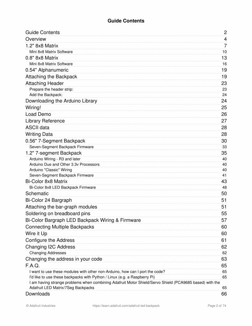
Adafruit LED Backpacks Created by lady ada Last updated on 2017-12-26 06:12:13 PM UTC
Transcript of Adafruit LED Backpacks
Adafruit LED BackpacksCreated by lady ada
Last updated on 2017-12-26 06:12:13 PM UTC
247
10
1316
1919232324
2425262728283033
3540404041
4348
50515155576060616262
63656565
65
66
Guide Contents
Guide ContentsOverview1.2" 8x8 Matrix
Mini 8x8 Matrix Software
0.8" 8x8 MatrixMini 8x8 Matrix Software
0.54" AlphanumericAttaching the BackpackAttaching Header
Prepare the header strip:Add the Backpack:
Downloading the Arduino LibraryWiring!Load DemoLibrary ReferenceASCII dataWriting Data0.56" 7-Segment Backpack
Seven-Segment Backpack Firmware
1.2" 7-segment BackpackArduino Wiring - R3 and laterArduino Due and Other 3.3v ProcessorsArduino "Classic" WiringSeven-Segment Backpack Firmware
Bi-Color 8x8 MatrixBi-Color 8x8 LED Backpack Firmware
SchematicBi-Color 24 BargraphAttaching the bar-graph modulesSoldering on breadboard pinsBi-Color Bargraph LED Backpack Wiring & FirmwareConnecting Multiple BackpacksWire it UpConfigure the AddressChanging I2C Address
Changing Addresses
Changing the address in your codeF.A.Q.
I want to use these modules with other non-Arduino, how can I port the code?I'd like to use these backpacks with Python / Linux (e.g. a Raspberry Pi)I am having strange problems when combining Adafruit Motor Shield/Servo Shield (PCA9685 based) with theAdafruit LED Matrix/7Seg Backpacks
Downloads
© Adafruit Industries https://learn.adafruit.com/adafruit-led-backpack Page 2 of 74
6666666768697071727273
SoftwareFilesHT16K33 8x16 LED Backpack Breakout8x8 0.8" LED Backpack8x8 1.2" LED Backpack8x8 1.2" Bi-Color LED Backpack16x8 1.2" LED BackpacksQuad 0.56" 7-SegmentQuad 0.54" 14-segment AlphanumericQuad 1.2" 7-SegmentBicolor 24-Bargraph
© Adafruit Industries https://learn.adafruit.com/adafruit-led-backpack Page 3 of 74

OverviewWhat's better than a single LED? Lots of LEDs! A fun way to make a small display is to use an 8x8 matrix or a 4-digit 7-segment display. Matrices like these are 'multiplexed' - so to control 64 LEDs you need 16 pins. That's a lot of pins, andthere are driver chips like the MAX7219 that can control a matrix for you but there's a lot of wiring to set up and theytake up a ton of space. Here at Adafruit we feel your pain! After all, wouldn't it be awesome if you could control a matrixwithout tons of wiring? That's where these adorable LED matrix backpacks come in.
We have them in quite a few flavors!
Adorable Mini 8x8Classic 1.2" 8x8 (round and square dots)4-digit 0.56" 7-segment4-digit 1.2" 7-segment4-digit 0.54" 14-segment AlphanumericBi-color 8x8Bi-color Bargraph
© Adafruit Industries https://learn.adafruit.com/adafruit-led-backpack Page 4 of 74

The matrices use a driver chip that does all the heavy lifting for you: They have a built in clock so they multiplex thedisplay. They use constant-current drivers for ultra-bright, consistant color (the images above are photographed at thedimmest setting to avoid overloading our camera!), 1/16 step display dimming, all via a simple I2C interface. Thebackpacks come with address-selection jumpers so you can connect up to four mini 8x8's or eight 7-segments (or acombination, such as four mini 8x8's and four 7-segments, etc) on a single I2C bus.
© Adafruit Industries https://learn.adafruit.com/adafruit-led-backpack Page 5 of 74

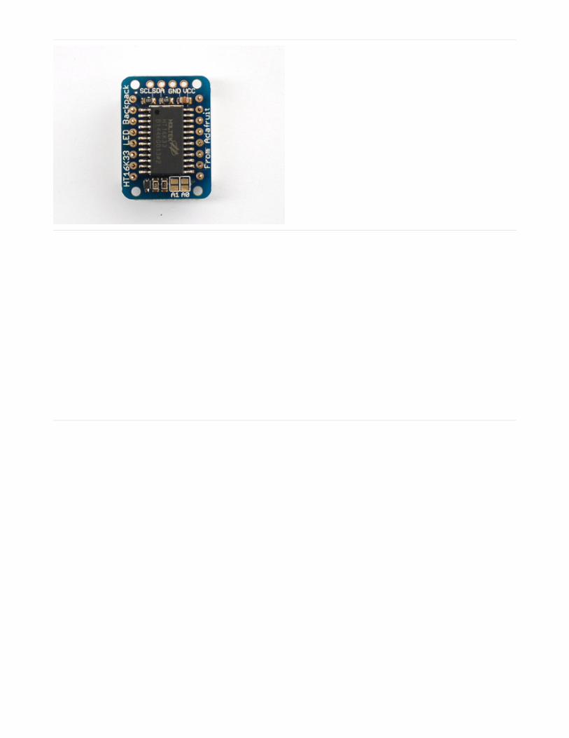
The product kit comes with a fully tested and assembled LED backpack, a 4-pin header and the matrix of your choice.A bit of soldering is required to attach the matrix onto the backpack but its very easy to do and only takes about 5minutes.
Of course, in classic Adafruit fashion, we also have a detailed tutorial showing you how to solder, wire and control thedisplay. We even wrote a very nice library for the backpacks so you can get running in under half an hour, displayingimages on the matrix or numbers on the 7-segment. If you've been eyeing matrix displays but hesitated because of thecomplexity, his is the solution you've been looking for!
© Adafruit Industries https://learn.adafruit.com/adafruit-led-backpack Page 6 of 74

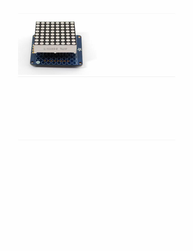
1.2" 8x8 MatrixThis version of the LED backpack is designed for the 1.2" 8x8 matrices. They measure only 1.2"x1.2" so its a shame touse a massive array of chips to control it. This backpack solves the annoyance of using 16 pins or a bunch of chips byhaving an I2C constant-current matrix controller sit neatly on the back of the PCB. The controller chip takes care ofeverything, drawing all 64 LEDs in the background. All you have to do is write data to it using the 2-pin I2C interface.There are two address select pins so you can select one of 8 addresses to control up to 8 of these on a single 2-pinI2C bus (as well as whatever other I2C chips or sensors you like). The driver chip can 'dim' the entire display from 1/16brightness up to full brightness in 1/16th steps. It cannot dim individual LEDs, only the entire display at once.
When you buy a pack from Adafruit, it comes with the
fully tested and assembled backpack as well as a 8x8
matrix in one of the colors we provide (say, red, yellow
or green). You'll need to solder the matrix onto the
backpack but its an easy task.
WATCH OUT! THE MATRIX MUST BE INSTALLED THE
RIGHT WAY!
First look for the line of text on the side of the LED
matrix
These instruction apply to the 1.2" Matrix only! If you have a Bi-Color or 0.8" square matrix, follow the links onthe left side of the page.
© Adafruit Industries https://learn.adafruit.com/adafruit-led-backpack Page 7 of 74
WATCH OUT! THE MATRIX MUST BE INSTALLED THE
RIGHT WAY!
Find the corner of the backpack with a filled in dot.
Make sure that the text on the side of the matrix is on
the same side as the filled dot
WATCH OUT! THE MATRIX MUST BE INSTALLED THE
RIGHT WAY!
Slide the matrix into the backpack and flip it over. Triple
check that the text is on the same side as the From
Adafruit text
© Adafruit Industries https://learn.adafruit.com/adafruit-led-backpack Page 8 of 74
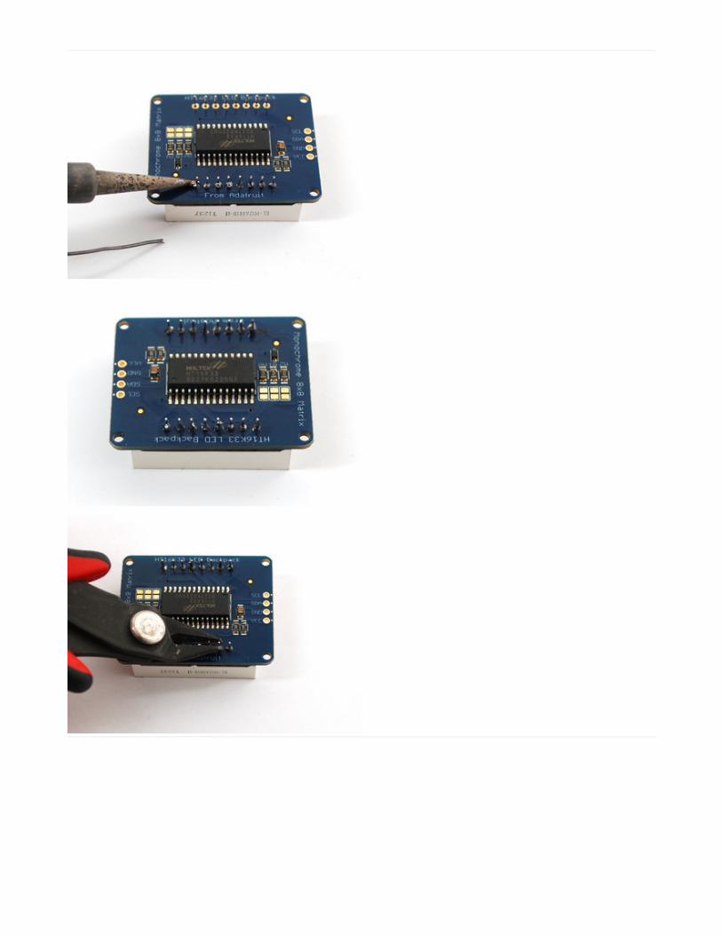
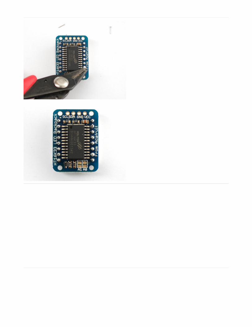
Solder in all 16 pins
Then clip the matrix leads short
© Adafruit Industries https://learn.adafruit.com/adafruit-led-backpack Page 9 of 74
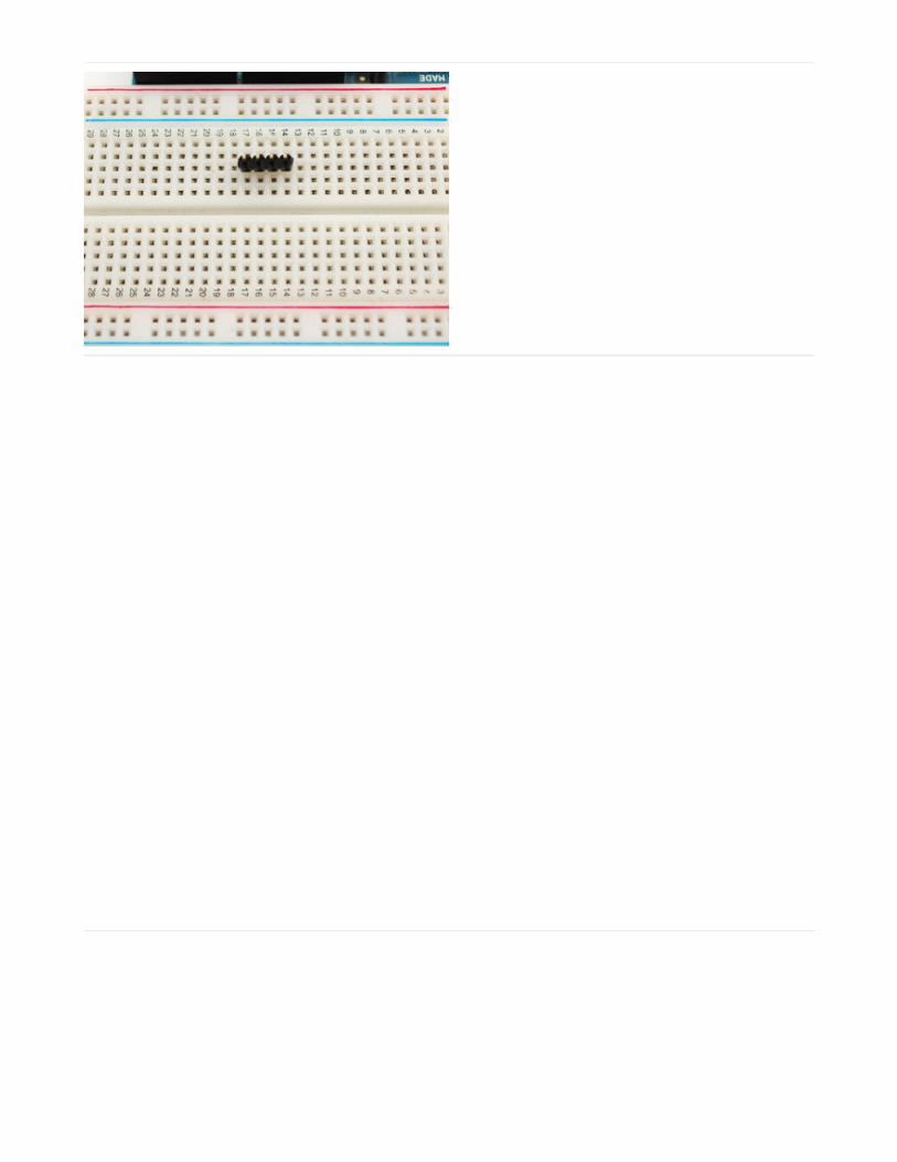
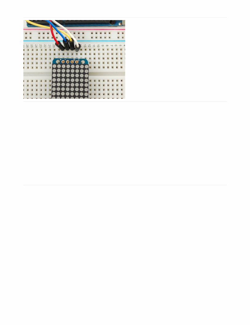
Now you're ready to wire it up to a microcontroller. We'll
assume you want to use a 4pin header. You can also of
course solder wires directly. Place a 4-pin piece of
header with the LONG pins down into the breadboard.
Place the soldered backpack on top of the header.
Solder the four pins
That's it! now you're ready to run the firmware!
Mini 8x8 Matrix SoftwareWe wrote a basic library to help you work with the mini 8x8 matrix backpack. The library is written for the Arduino andwill work with any Arduino as it just uses the I2C pins. The code is very portable and can be easily adapted to any I2C-
© Adafruit Industries https://learn.adafruit.com/adafruit-led-backpack Page 10 of 74

capable micro.
Wiring to the matrix is really easy
Connect CLK to the I2C clock - on Arduino UNO thats Analog #5, on the Leonardo its Digital #3, on the Mega itsdigital #21Connect DAT to the I2C data - on Arduino UNO thats Analog #4, on the Leonardo its Digital #2, on the Mega itsdigital #20Connect GND to common groundConnect VCC+ to power - 5V is best but 3V also seems to work for 3V microcontrollers.
Next, download the Adafruit LED Backpack library from github . To download click the DOWNLOADS button in the topright corner, rename the uncompressed folder Adafruit_LEDBackpack. Check that the Adafruit_LEDBackpack foldercontains Adafruit_LEDBackpack.cpp and Adafruit_LEDBackpack.h Place the Adafruit_LEDBackpack library folderyour arduinosketchfolder/libraries/ folder. You may need to create the libraries subfolder if its your first library. You'llalso need to download the Adafruit GFX library that provides the graphics drawing routines. Restart the IDE.
Once you've restarted you should be able to select the File->Examples->Adafruit_LEDBackpack->matrix88 examplesketch. Upload it to your Arduino as usual. You should see a basic test program that goes through a bunch of differentdrawing routine
Once you're happy that the matrix works, you can write your own sketches. The 8x8 matrix supports everything theAdafruit GFX library - drawing pixels, lines, rectancles, circles, triangles, roundrects, and small bitmaps. For more detailscheck out the GFX page which will detail all of the GFX routines.
All the drawing routines only change the display memory kept by the Arduino. Don't forget to call writeDisplay() afterdrawing to 'save' the memory out to the matrix via I2C.
© Adafruit Industries https://learn.adafruit.com/adafruit-led-backpack Page 11 of 74

There are also a few small routines that are special to the matrix:
setBrightness(brighness)- will let you change the overall brightness of the entire display. 0 is least bright, 15 isbrightest and is what is initialized by the display when you start. You can call this function at any time to changethe brightness of the -entire- displayblinkRate(rate) - You can blink the entire display. 0 is no blinking. 1, 2 or 3 is for display blinking.You can call thisfunction at any time to change the blink rate of the -entire- display
The default orientation for graphics commands on this
display places pixel (0,0) at the top-left when the header
is at the left and Adafruit logo at the right. To use the
matrix as shown above (header at top, logo at bottom),
call matrix.setRotation(3) before issuing graphics
commands.
© Adafruit Industries https://learn.adafruit.com/adafruit-led-backpack Page 12 of 74

0.8" 8x8 MatrixThis version of the LED backpack is designed for these very cute miniature 8x8 matrices. They measure only 0.8"x0.8"so its a shame to use a massive array of chips to control it. This backpack solves the annoyance of using 16 pins or abunch of chips by having an I2C constant-current matrix controller sit neatly on the back of the PCB. The controllerchip takes care of everything, drawing all 64 LEDs in the background. All you have to do is write data to it using the 2-pin I2C interface. There are two address select pins so you can select one of 4 addresses to control up to 4 of these ona single 2-pin I2C bus (as well as whatever other I2C chips or sensors you like). The driver chip can 'dim' the entiredisplay from 1/16 brightness up to full brightness in 1/16th steps. It cannot dim individual LEDs, only the entire display atonce.
When you buy a pack from Adafruit, it comes with the
fully tested and assembled backpack as well as a 8x8
matrix in one of the colors we provide (say, red, yellow
or green). You'll need to solder the matrix onto the
backpack but its an easy task.
Remove the parts from packaging and place the LED
matrix OVER the silkscreen side. It can go 'either way' -
the matrix is symmetric so as long as it goes onto the
front it will work in any orientation. Do not solder the
matrix over the chip on the back of the backpack - it will
not work then!
These instruction apply to the 0.8" Matrix only! If you have a Bi-Color or 1.2" square matrix, follow the links onthe left side of the page.
© Adafruit Industries https://learn.adafruit.com/adafruit-led-backpack Page 13 of 74
Turn the backpack over so its sitting flat on the matrix.
Solder all 16 pins.
© Adafruit Industries https://learn.adafruit.com/adafruit-led-backpack Page 14 of 74
Clip the long pins.
Now you're ready to wire it up to a microcontroller. We'll
assume you want to use a 4pin header. You can also of
course solder wires directly. Place a 4-pin piece of
header with the LONG pins down into the breadboard.
© Adafruit Industries https://learn.adafruit.com/adafruit-led-backpack Page 15 of 74
Place the soldered backpack on top of the header.
Solder 'em!
That's it! now you're ready to run the firmware!
Mini 8x8 Matrix SoftwareWe wrote a basic library to help you work with the mini 8x8 matrix backpack. The library is written for the Arduino andwill work with any Arduino as it just uses the I2C pins. The code is very portable and can be easily adapted to any I2C-capable micro.
Wiring to the matrix is really easy
Connect CLK to the I2C clock - on Arduino UNO thats Analog #5, on the Leonardo its Digital #3, on the Mega itsdigital #21Connect DAT to the I2C data - on Arduino UNO thats Analog #4, on the Leonardo its Digital #2, on the Mega itsdigital #20Connect GND to common groundConnect VCC+ to power - 5V is best but 3V also seems to work for 3V microcontrollers.
Next, download the Adafruit LED Backpack library from github . To download click the DOWNLOADS button in the topright corner, rename the uncompressed folder Adafruit_LEDBackpack. Check that the Adafruit_LEDBackpack foldercontains Adafruit_LEDBackpack.cpp and Adafruit_LEDBackpack.h Place the Adafruit_LEDBackpack library folder
© Adafruit Industries https://learn.adafruit.com/adafruit-led-backpack Page 16 of 74

your arduinosketchfolder/libraries/ folder. You may need to create the libraries subfolder if its your first library.
You'll also need to download the Adafruit GFX library that provides the graphics drawing routines. Follow the sameinstructions as above, but with Adafruit_GFX instead of Adafruit_LEDBackpack.
Restart the IDE.
Once you've restarted you should be able to select the File->Examples->Adafruit_LEDBackpack->matrix88 examplesketch. Upload it to your Arduino as usual. You should see a basic test program that goes through a bunch of differentdrawing routines
Once you're happy that the matrix works, you can write your own sketches. The 8x8 matrix supports everything theAdafruit GFX library - drawing pixels, lines, rectancles, circles, triangles, roundrects, and small bitmaps. For more detailscheck out the GFX page which will detail all of the GFX routines.
All the drawing routines only change the display memory kept by the Arduino. Don't forget to call writeDisplay() afterdrawing to 'save' the memory out to the matrix via I2C.
There are also a few small routines that are special to the matrix:
setBrightness(brighness)- will let you change the overall brightness of the entire display. 0 is least bright, 15 isbrightest and is what is initialized by the display when you startblinkRate(rate) - You can blink the entire display. 0 is no blinking. 1, 2 or 3 is for display blinking.
© Adafruit Industries https://learn.adafruit.com/adafruit-led-backpack Page 17 of 74

The default orientation for graphics commands on this
display places pixel (0,0) at the top-left when the header
is at the top and Adafruit logo at the bottom.
matrix.setRotation() can be used to use the display in
other orientations.
© Adafruit Industries https://learn.adafruit.com/adafruit-led-backpack Page 18 of 74

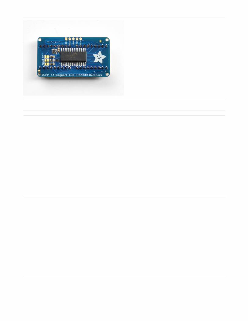
0.54" Alphanumeric
This version of the LED backpack is designed for two dual 14-segment "Alphanumeric" displays. These 14-segmentdisplays normally require 18 pins (4 'characters' and 14 total segments each) This backpack solves the annoyance ofusing 18 pins or a bunch of chips by having an I2C constant-current matrix controller sit neatly on the back of the PCB.The controller chip takes care of everything, drawing all the LEDs in the background. All you have to do is write data toit using the 2-pin I2C interface.
There are three address select pins so you can select one of 8 addresses to control up to 8 of these on a single 2-pinI2C bus (as well as whatever other I2C chips or sensors you like). The driver chip can 'dim' the entire display from 1/16brightness up to full brightness in 1/16th steps. It cannot dim individual LEDs, only the entire display at once.
Attaching the Backpack
When you buy a pack from Adafruit, it comes with the
fully tested and assembled backpack as well as two dual
14-segment display in one of the colors we provide (say,
red, yellow, blue or green). You'll need to solder the
matrix onto the backpack but it's an easy task.
Remove the parts from packaging and place the LED
matrices OVER the silkscreen side. DO NOT PUT THE
DISPLAY ON UPSIDE DOWN OR IT WONT WORK!!
Check the image below to make sure the 'decimal
point' dots are on the bottom, matching the silkscreen.
© Adafruit Industries https://learn.adafruit.com/adafruit-led-backpack Page 19 of 74
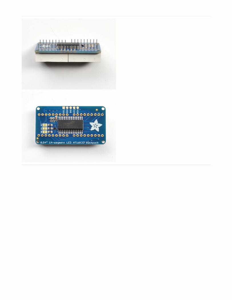
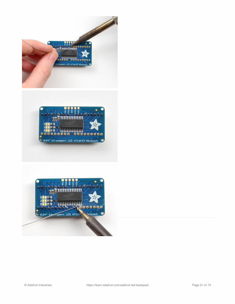
Turn the backpack over so it is sitting flat on the matrix.
Solder all of the pins!
© Adafruit Industries https://learn.adafruit.com/adafruit-led-backpack Page 20 of 74
© Adafruit Industries https://learn.adafruit.com/adafruit-led-backpack Page 21 of 74
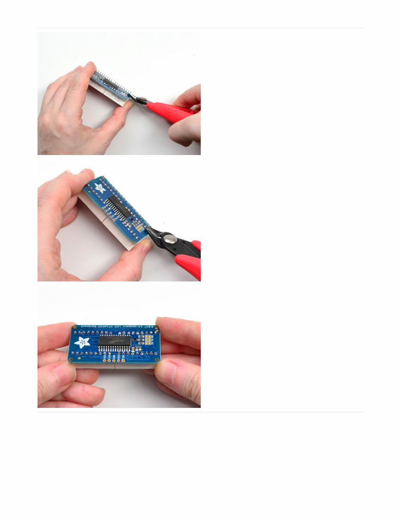
Clip the long pins.
© Adafruit Industries https://learn.adafruit.com/adafruit-led-backpack Page 22 of 74
Check your work, making sure each pin is nicely
soldered, and there's no cold solder joints or shorted
pins
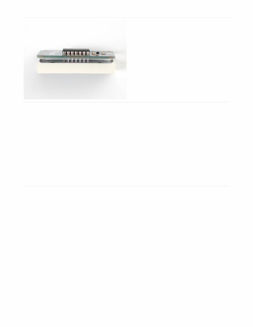
Attaching Header
Prepare the header strip:Cut the strip to length if necessary. It will be easier to
solder if you insert it into a breadboard - long pins down
Add the Backpack:Place the backpack board over the pins so that the short
pins poke through the breakout pads
© Adafruit Industries https://learn.adafruit.com/adafruit-led-backpack Page 23 of 74
Solder all 5 pins!
That's it! now you're ready to run the firmware on your Arduino!
Downloading the Arduino LibraryWe wrote a basic library to help you work with the alphanumeric backpack. The library is written for the Arduino andwill work with any Arduino as it just uses the I2C pins. The code is very portable and can be easily adapted to any I2C-capable micro.
Begin by downloading our Adafruit LED Backpack library from github. You can do that by visiting the github repo andmanually downloading or, easier, just click this button to download the zip
Download LED Backpack Library
https://adafru.it/dxh
Rename the uncompressed folder Adafruit_LEDBackpack and check that the Adafruit_LEDBackpack folder containsAdafruit_LEDBackpack.cpp and Adafruit_LEDBackpack.h
Place the Adafruit_LEDBackpack library folder your arduinosketchfolder/libraries/ folder. You may need to create the libraries subfolder if its your first library. Restart the IDE.
We also have a great tutorial on Arduino library installation at:http://learn.adafruit.com/adafruit-all-about-arduino-libraries-install-use
You'll also need to download the Adafruit GFX library - even though this particular backpack doesn't use it! Its just oneof those Arduino dependencies! You can grab the Adafruit GFX library from github or download by clicking below.
Download Adafruit GFX Library
https://adafru.it/cBB
Rename the uncompressed folder Adafruit_GFX and check that the Adafruit_GFX folder contains Adafruit_GFX.cppand Adafruit_GFX.h
Place the Adafruit_GFX library folder your arduinosketchfolder/libraries/ folder like you did with the LED backpacks
© Adafruit Industries https://learn.adafruit.com/adafruit-led-backpack Page 24 of 74

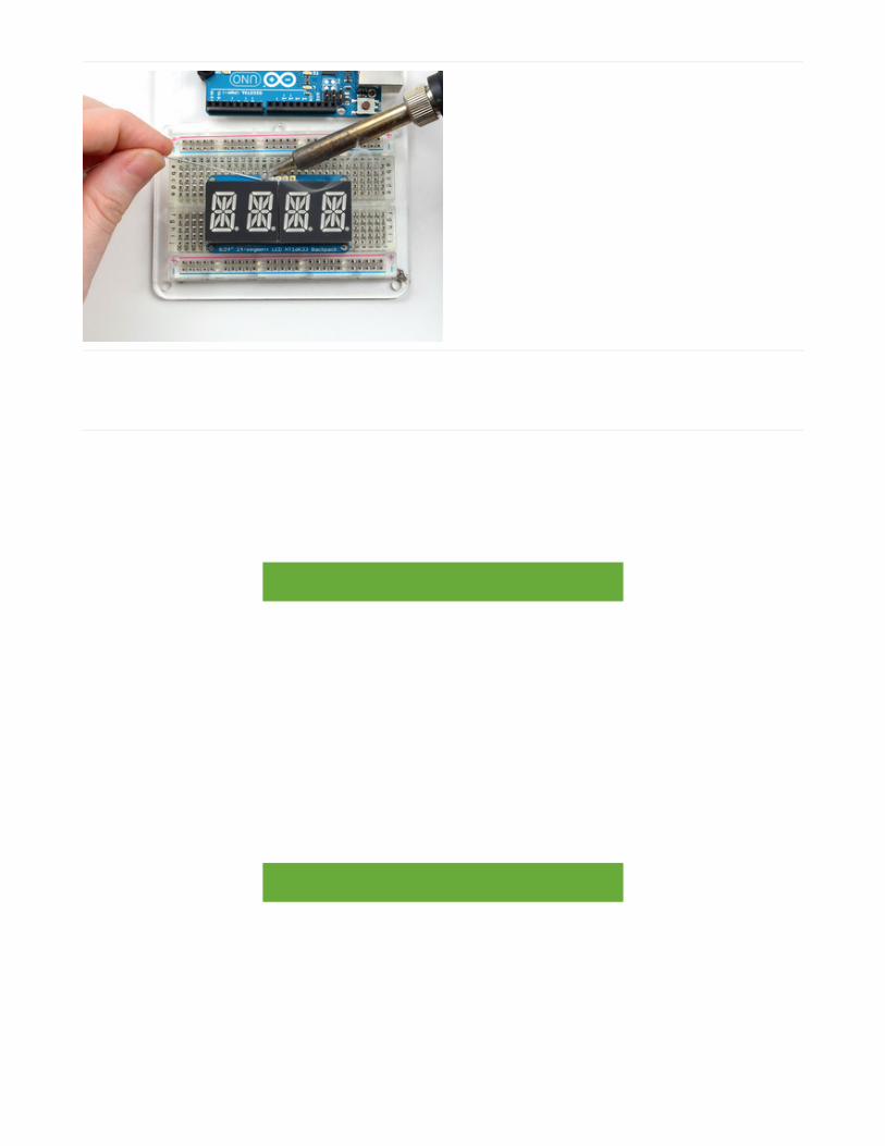
Wiring!Nex up, let's wire it up to an Arduino. We'll be using an Arduino.
Connect CLK to the I2C clock - on Arduino UNO thats Analog #5, on the Leonardo it's Digital #3, on the Mega it'sdigital #21Connect DAT to the I2C data - on Arduino UNO thats Analog #4, on the Leonardo it's Digital #2, on the Mega it'sdigital #20Connect GND to common groundConnect VCC+ to power - 5V is best but 3V will work if that's all you've got (it will be dimmer)Connect Vi2c to your microcontroller's logic level (3-5V) - If you're using an Arduino, this is almost certainly 5V. Ifits a 3V Arduino such as a Due, connect it to 3V
Both Vi2c and Vcc MUST be connected to 3 to 5VDC! Vcc is for the LED driver power, Vi2c is what sets the logic levelfor communication to the chip.
Load DemoRestart the Arduino IDE and load up the File->Adafruit_LEDBackpack->quadalphanum demo
© Adafruit Industries https://learn.adafruit.com/adafruit-led-backpack Page 25 of 74

Upload to your Arduino, and open up the Serial console at 9600 baud speed. You'll see each digit light up all thesegments, then the display will scroll through the 'font table' showing every character that it knows how to display.Finally, you'll get a notice to start typing into the serial console. Type a message and hit return, you'll see it scroll ontothe display!
© Adafruit Industries https://learn.adafruit.com/adafruit-led-backpack Page 26 of 74

Library ReferenceFor the quad displays, we have a special object that can handle ascii data for easy printing.
You can create the object with
There's no arguments or pins because the backpacks use the fixed I2C pins.By default, the address is 0x70, but you can pass in the I2C address used when you initialize the display with begin
Next up, the segments can be turned on/off for each digit by writing the 'raw' bitmap you want, for example, all theLEDs off on digit #3 is
All the segments on for digit #0 is
This is the segment map:
Adafruit_AlphaNum4 alpha4 = Adafruit_AlphaNum4();
alpha4.begin(0x70); // pass in the address
alpha4.writeDigitRaw(3, 0x0);
alpha4.writeDigitRaw(0, 0x3FFF);
© Adafruit Industries https://learn.adafruit.com/adafruit-led-backpack Page 27 of 74

the 16 bit digit you pass in for raw image has this mapping:
0 DP N M L K J H G2 G1 F E D C B A
The first bit isn't used, you can make it 0 or 1
To turn on just the A segment, use 0x0001To turn on just the G1 segment, use 0x0040
ASCII dataIf you're just looking to print 'text' you can use our font table, just pass in an ASCII character!
For example, to set digit #0 to A call:
Writing DataDon't forget to 'write' the data to the display with
That's what actually 'sets' the data onto the LEDs!
alpha4.writeDigitAscii(0, 'A')
alpha4.writeDisplay();
© Adafruit Industries https://learn.adafruit.com/adafruit-led-backpack Page 28 of 74

0.56" 7-Segment BackpackThis version of the LED backpack is designed for these big bright 7-segment displays. These 7-segment displaysnormally require 13 pins (5 'characters' and 8 total segments each) This backpack solves the annoyance of using 13pins or a bunch of chips by having an I2C constant-current matrix controller sit neatly on the back of the PCB. Thecontroller chip takes care of everything, drawing all the LEDs in the background. All you have to do is write data to itusing the 2-pin I2C interface. There are three address select pins so you can select one of 8 addresses to control up to8 of these on a single 2-pin I2C bus (as well as whatever other I2C chips or sensors you like). The driver chip can 'dim'the entire display from 1/16 brightness up to full brightness in 1/16th steps. It cannot dim individual LEDs, only the entiredisplay at once.
When you buy a pack from Adafruit, it comes with the
fully tested and assembled backpack as well as a 7-
segment display in one of the colors we provide (say,
red, yellow, blue or green). You'll need to solder the
matrix onto the backpack but it's an easy task.
Remove the parts from packaging and place the LED
matrix OVER the silkscreen side. DO NOT PUT THE
DISPLAY ON UPSIDE DOWN OR IT WONT WORK!!
Check the image below to make sure the 'decimal
point' dots are on the bottom, matching the silkscreen.
© Adafruit Industries https://learn.adafruit.com/adafruit-led-backpack Page 29 of 74
Turn the backpack over so it is sitting flat on the matrix.
Solder all 14 pins.
© Adafruit Industries https://learn.adafruit.com/adafruit-led-backpack Page 30 of 74
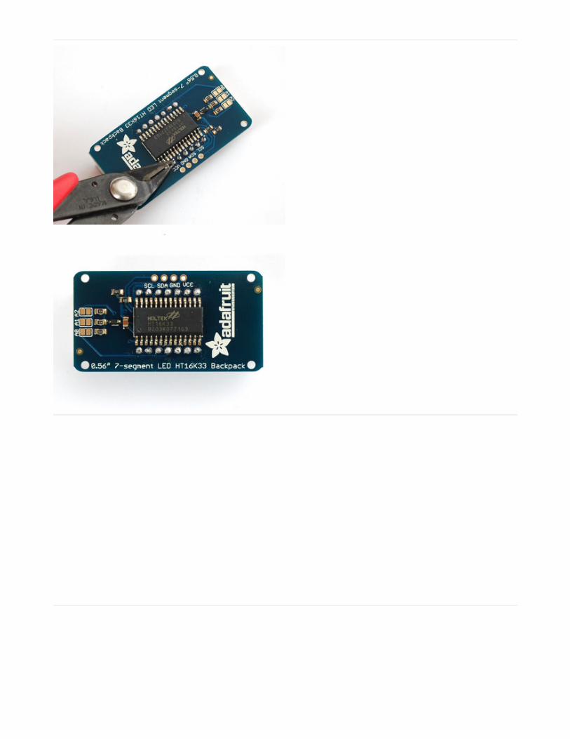
Clip the long pins.
Now you're ready to wire it up to a microcontroller. We'll
assume you want to use a 4pin header. You can also of
course solder wires directly. Place a 4-pin piece of
header with the LONG pins down into the breadboard.
© Adafruit Industries https://learn.adafruit.com/adafruit-led-backpack Page 31 of 74
Place the soldered backpack on top of the header and
Solder 'em!
That's it! now you're ready to run the firmware!
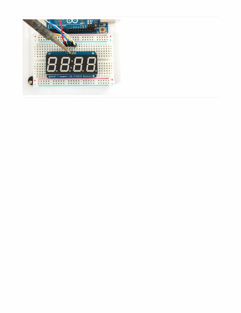
Seven-Segment Backpack FirmwareWe wrote a basic library to help you work with the 7-segment backpack. The library is written for the Arduino and willwork with any Arduino as it just uses the I2C pins. The code is very portable and can be easily adapted to any I2C-capable micro.
Wiring to the matrix is really easy
Connect CLK to the I2C clock - on Arduino UNO thats Analog #5, on the Leonardo it's Digital #3, on the Mega it'sdigital #21Connect DAT to the I2C data - on Arduino UNO thats Analog #4, on the Leonardo it's Digital #2, on the Mega it'sdigital #20Connect GND to common groundConnect VCC+ to power - 5V is best but 3V also seems to work for 3V microcontrollers.
Next, download the Adafruit LED Backpack library from github . To download click the DOWNLOADS button in the topright corner, rename the uncompressed folder Adafruit_LEDBackpack. Check that the Adafruit_LEDBackpack foldercontains Adafruit_LEDBackpack.cpp and Adafruit_LEDBackpack.h Place the Adafruit_LEDBackpack library folderyour arduinosketchfolder/libraries/ folder. You may need to create the libraries subfolder if it's your first library. You'llalso need to download the Adafruit GFX library - rename it Adafruit_GFX and install it as the LED backpack library. It'snot actually used for the 7-segment, it's only for the matrix backpacks but it's still required. Restart the IDE.
Once you've restarted you should be able to select the File?Examples?Adafruit_LEDBackpack?sevenseg examplesketch. Upload it to your Arduino as usual. You should see a basic test program that goes through a bunch of differentroutines.
© Adafruit Industries https://learn.adafruit.com/adafruit-led-backpack Page 32 of 74

Once you're happy that the matrix works, you can write your own sketches.
There's a few ways you can draw to the display. The easiest is to just call print - just like you do with Serial
print(variable,HEX) - this will print a hexidecimal number, from 0000 up to FFFFprint(variable,DEC) or print(variable) - this will print a decimal integer, from 0000 up to 9999
If you need more control, you can call writeDigitNum(location, number) - this will write the number (0-9) to a singlelocation. Location #0 is all the way to the left, location #2 is the colon dots so you probably want to skip it, location #4is all the way to the right. If you want a decimal point, call writeDigitNum(location, number, true) which will paint thedecimal point. To draw the colon, usedrawColon(true or false)
If you want even more control, you can call writeDigitRaw(location,bitmask) to draw a raw 8-bit mask (as stored in auint8_t) to that location.
All the drawing routines only change the display memory kept by the Arduino. Don't forget to call writeDisplay() afterdrawing to 'save' the memory out to the matrix via I2C.
There are also a few small routines that are special to the backpack:
setBrightness(brightness)- will let you change the overall brightness of the entire display. 0 is least bright, 15 isbrightest and is what is initialized by the display when you startblinkRate(rate) - You can blink the entire display. 0 is no blinking. 1, 2 or 3 is for display blinking.
© Adafruit Industries https://learn.adafruit.com/adafruit-led-backpack Page 33 of 74

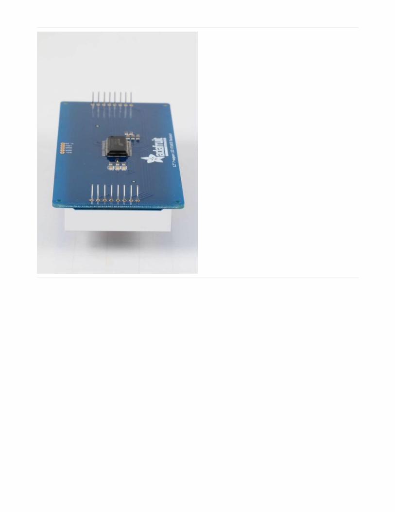
1.2" 7-segment BackpackThese backpacks drive the massive 1.2" 7-segment modules. With 2 leds per segment these make a gorgeous andimpressive display. The 7-segment displays normally require 16 pins to drive. This backpack uses an I2C constant-current matrix controller on the back of the PCB, so you only need 2 pins to drive it!
The controller chip takes care of multiplexing all the LEDs in the background. All you have to do is write data to it usingthe 2-pin I2C interface. There are three address select pins so you can select one of 8 addresses to control up to 8 ofthese on a single 2-pin I2C bus (as well as whatever other I2C chips or sensors you like). The driver chip can 'dim' theentire display from 1/16 brightness up to full brightness in 1/16th steps. It cannot dim individual LEDs, only the entiredisplay at once.
When you buy a pack from Adafruit, it comes with the
fully tested and assembled backpack as well as a 7-
segment display in one of the colors we provide (say,
red, yellow, blue or green). You'll need to solder the
matrix onto the backpack but its an easy task.
Remove the parts from packaging and place the LED
matrix OVER the silkscreen side. DO NOT PUT THE
DISPLAY ON UPSIDE DOWN OR IT WONT WORK!!
Check the image below to make sure the 'decimal
point' dots are in the same location as the ones on the
silkscreen.
© Adafruit Industries https://learn.adafruit.com/adafruit-led-backpack Page 34 of 74
Turn the backpack over so its sitting flat on the matrix
and ready to solder.
© Adafruit Industries https://learn.adafruit.com/adafruit-led-backpack Page 35 of 74
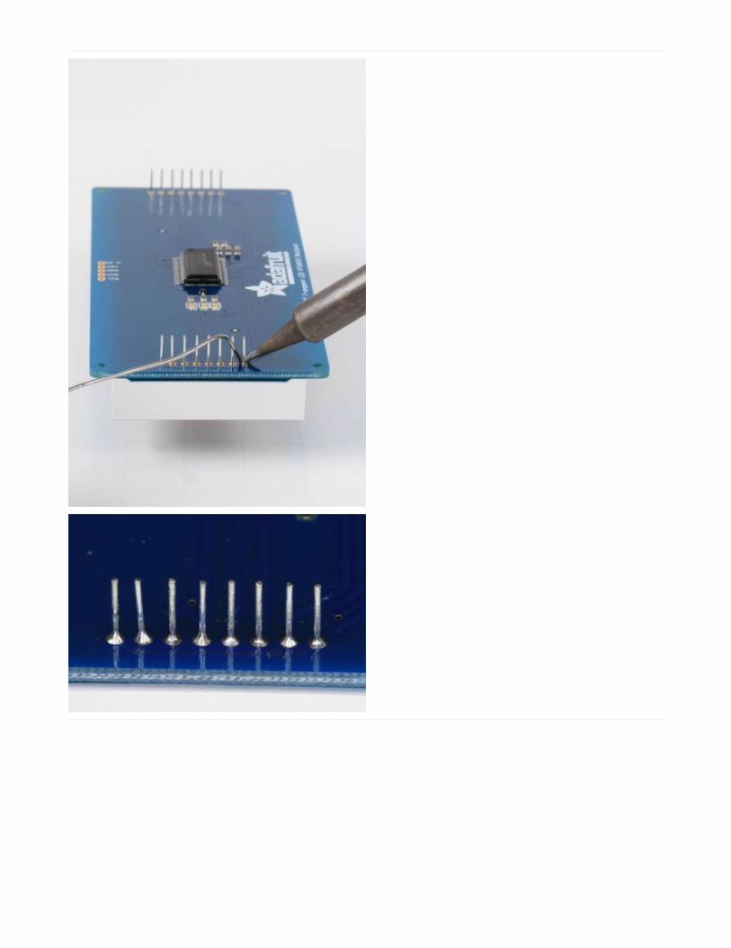
Then solder each pin. There are 8 on each end for a
total of 16.
That completes the basic assembly. For use on a breadboard, you will want to also install a 5-pin header on the edgeof the board.
© Adafruit Industries https://learn.adafruit.com/adafruit-led-backpack Page 36 of 74

Clip the long pins close to the board.
Cut the header strip to length if necessary and insert
LONG pins down into the breadboard.
© Adafruit Industries https://learn.adafruit.com/adafruit-led-backpack Page 37 of 74
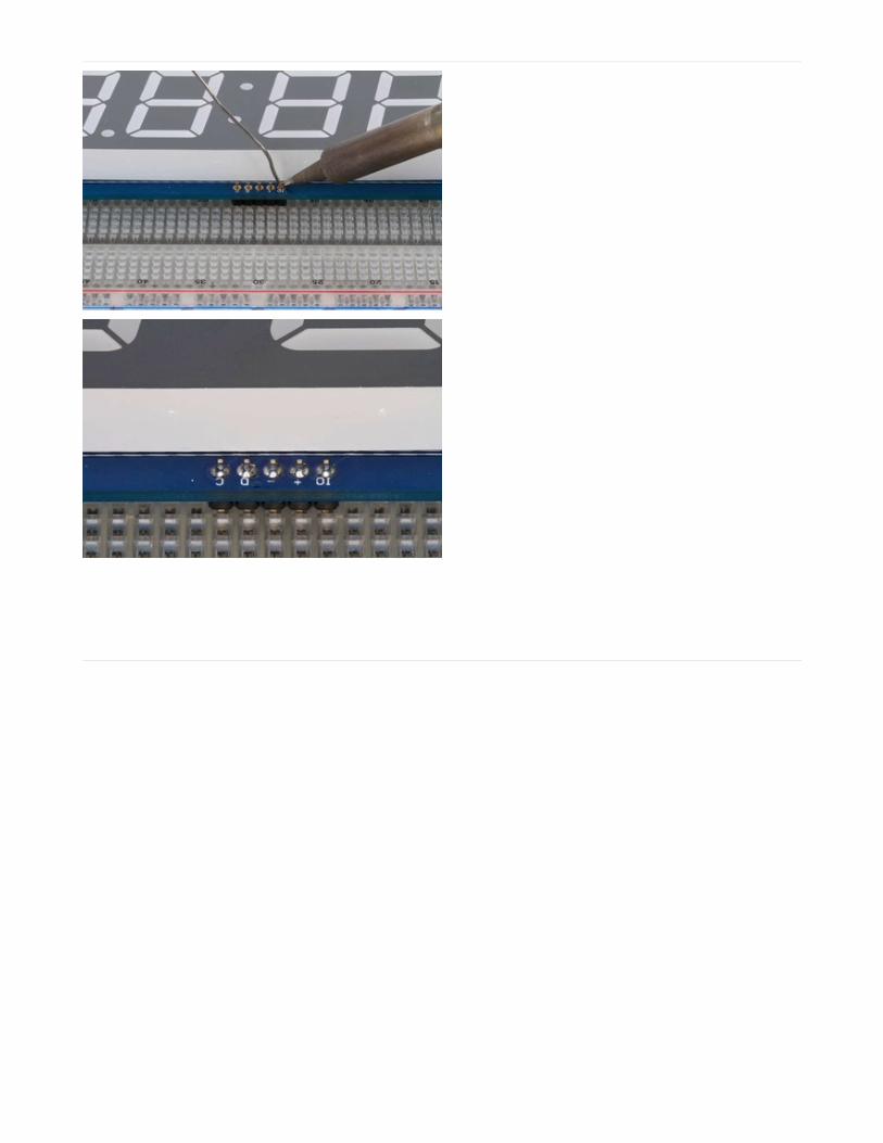
Then solder all 5 pins.
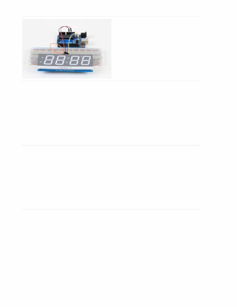
Now you are ready to wire it to your microcontroller. The required connections are:
"D" - I2C Data Pin (SDA)"C" - I2C Clock Pin (SCL)"+" - 5v. (Will not run on 3.3v!)"-" - GND"IO" - I2C bus voltage.
Due to the size of this display, there are 2 LEDs in series for each segment. Because of this, the display requires 5v torun. It will not run on 3.3v.
For use with 3.3v processors, connect the IO pin to 3.3v. This will keep the I2C bus signals at a safe level for yourprocessor.
With 5v processors like the Arduino UNO, this pin can be connected to either 5v or 3.3v. (use 3.3v if there will be other3.3v devices on the bus)
© Adafruit Industries https://learn.adafruit.com/adafruit-led-backpack Page 38 of 74
Arduino Wiring - R3 and laterConnect:
D -> SDA
C -> SCL
+ -> 5v
- -> GND
IO -> jumper to + for 5v.
Arduino Due and Other 3.3vProcessorsConnect:
D -> SDA
C -> SCL
+ -> 5v
- -> GND
IO -> 3.3v
Arduino "Classic" WiringConnect:
D -> Analog-4 or Digital 20 for the Mega
C -> Analog-5 or Digital 21 for the Mega
+ -> 5v
- -> GND
IO -> jumper to + for 5v.
OK, now on to the firmware!
Seven-Segment Backpack FirmwareOur 7-segment backpack library makes it easy to program these displays. The library is written for the Arduino and willwork with any Arduino as it just uses the I2C pins. The code is very portable and can be easily adapted to any I2C-capable micro.
You can download the Adafruit LED Backpack library from github . To download click the DOWNLOADS button in thetop right corner, rename the uncompressed folder Adafruit_LEDBackpack. Check that the Adafruit_LEDBackpackfolder contains Adafruit_LEDBackpack.cpp and Adafruit_LEDBackpack.h.
If you need help with installing you libraries, we have a detailed guide here:
© Adafruit Industries https://learn.adafruit.com/adafruit-led-backpack Page 39 of 74

Installing Arduino Libraries
https://adafru.it/aYM
You'll also need to download the Adafruit GFX library - rename it Adafruit_GFX and install it as the LED backpacklibrary. Close all open IDE windows and restart the IDE.
Once you've restarted you should be able to select the File?Examples?Adafruit_LEDBackpack?sevenseg examplesketch. Upload it to your Arduino as usual. You should see a "sevenseg" example sketch that will demonstrate variouscapabilities of the library and the display.
Once you're happy that the matrix works, you can write your own sketches.
There's a few ways you can draw to the display. The easiest is to just call print - just like you do with Serial
print(variable,HEX) - this will print a hexidecimal number, from 0000 up to FFFFprint(variable,DEC) or print(variable) - this will print a decimal integer, from 0000 up to 9999
If you need more control, you can call writeDigitNum(location, number) - this will write the number (0-9) to a singlelocation. Location #0 is all the way to the left, location #2 is the colon dots so you probably want to skip it, location #4is all the way to the right.
To control the colon and decimal points, use the writeDigitRaw(location, bitmap) function. (Note that both dots of thecenter colon are wired together internal to the display, so it is not possible to address them separately.) Specify 2 forthe location and the bits are mapped as follows:
0x02 - center colon (both dots)0x04 - left colon - lower dot0x08 - left colon - upper dot0x10 - decimal point
© Adafruit Industries https://learn.adafruit.com/adafruit-led-backpack Page 40 of 74

If you want a decimal point, call writeDigitNum(location, number, true) which will paint the decimal point. To draw thecolon, use drawColon(true or false)
If you want full control of the segments in all digits, you can call writeDigitRaw(location,bitmask) to draw a raw 8-bitmask (as stored in a uint8_t) to anylocation.
All the drawing routines only change the display memory kept by the Arduino. Don't forget to call writeDisplay() afterdrawing to 'save' the memory out to the matrix via I2C.
There are also a few small routines that are special to the backpack:
setBrightness(brighness)- will let you change the overall brightness of the entire display. 0 is least bright, 15 isbrightest and is what is initialized by the display when you startblinkRate(rate) - You can blink the entire display. 0 is no blinking. 1, 2 or 3 is for display blinking.
© Adafruit Industries https://learn.adafruit.com/adafruit-led-backpack Page 41 of 74

Bi-Color 8x8 MatrixThis version of the LED backpack is designed for these bright and colorful square=pixeled 8x8 matrices. They have 64red and 64 green LEDs inside, for a total of 128 LEDs controlled as a 8x16 matrix. This backpack solves the annoyanceof using 24 pins or a bunch of chips by having an I2C constant-current matrix controller sit neatly on the back of thePCB. The controller chip takes care of everything, drawing all 128 LEDs in the background. All you have to do is writedata to it using the 2-pin I2C interface. There are three address select pins so you can select one of 8 addresses tocontrol up to 8 of these on a single 2-pin I2C bus (as well as whatever other I2C chips or sensors you like). The driverchip can 'dim' the entire display from 1/16 brightness up to full brightness in 1/16th steps. It cannot dim individual LEDs,only the entire display at once.
Pay close attention to the instructions for positioning the matrix. It must be oriented correctly to work and isalmost impossible to remove it once it has been soldered to the backpack!
© Adafruit Industries https://learn.adafruit.com/adafruit-led-backpack Page 42 of 74
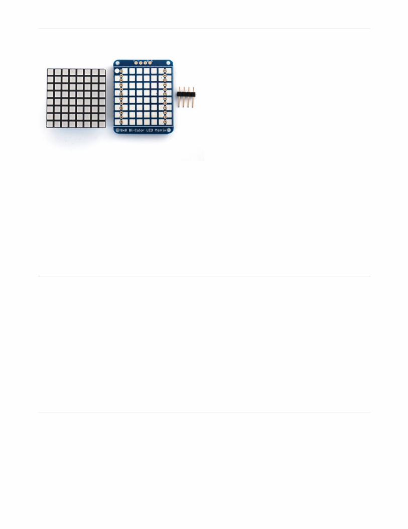
When you buy a pack from Adafruit, it comes with the
fully tested and assembled backpack as well as a 8x8
matrix. You'll need to solder the matrix onto the
backpack but its an easy task.
Remove the parts from packaging and place the LED
matrix OVER the silkscreen side.
The matrix must be soldered on the correct orientation
or it will not work! Check for the side of the matrix that
has printing on it. Then look for the front of the PCB
that has a circle instead of a square in the corner and
line those up as shown on the left
Do not solder the matrix over the chip on the back of
the backpack - it will not work then!
© Adafruit Industries https://learn.adafruit.com/adafruit-led-backpack Page 43 of 74
Turn the backpack over so its sitting flat on the matrix.
Solder all 24 pins.
© Adafruit Industries https://learn.adafruit.com/adafruit-led-backpack Page 44 of 74
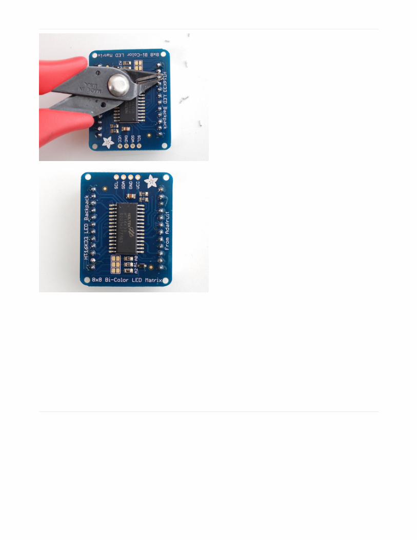
Clip the long pins
© Adafruit Industries https://learn.adafruit.com/adafruit-led-backpack Page 45 of 74
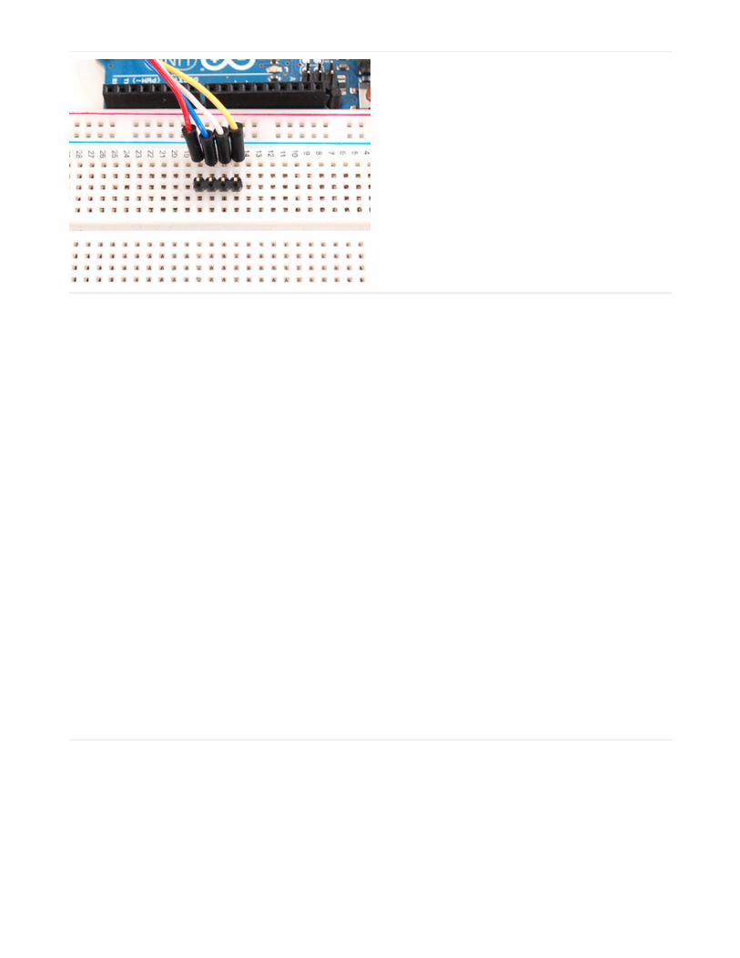
Now you're ready to wire it up to a microcontroller. We'll
assume you want to use a 4pin header. You can also of
course solder wires directly. Place a 4-pin piece of
header with the LONG pins down into the breadboard.
Place the soldered backpack on top of the header.
© Adafruit Industries https://learn.adafruit.com/adafruit-led-backpack Page 46 of 74
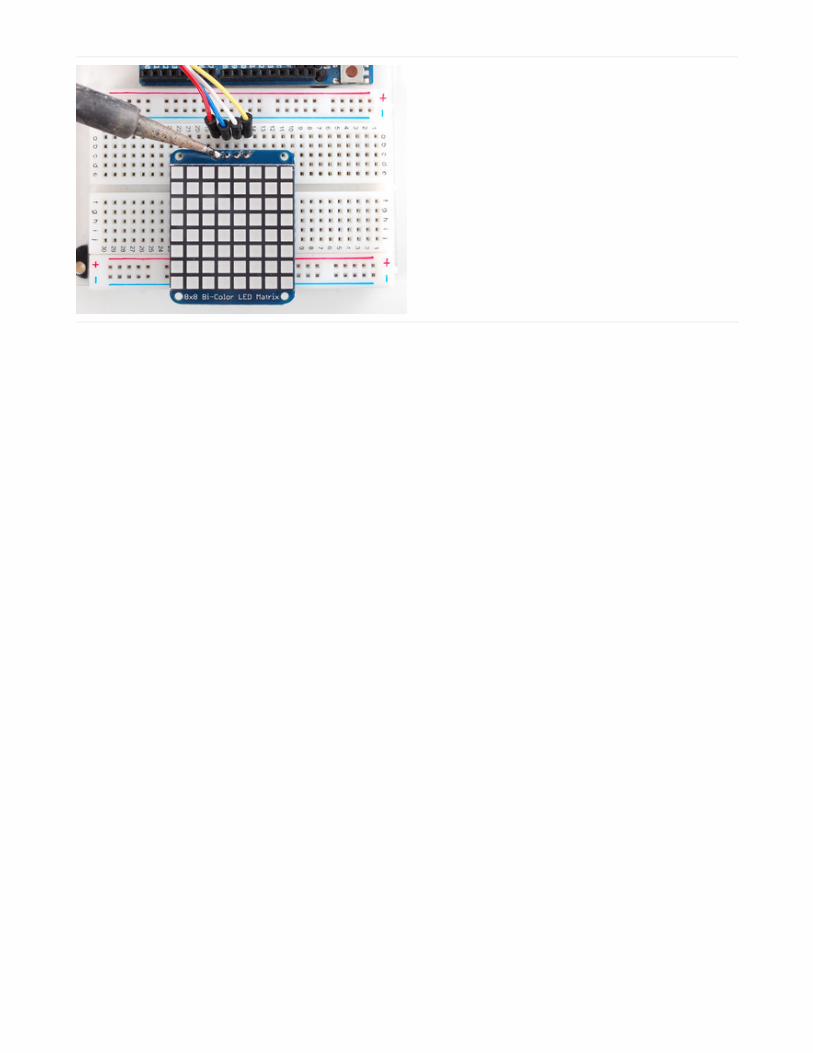
Solder 'em!
Bi-Color 8x8 LED Backpack FirmwareWe wrote a basic library to help you work with the bi-color 8x8 matrix backpack. The library is written for the Arduinoand will work with any Arduino as it just uses the I2C pins. The code is very portable and can be easily adapted to anyI2C-capable micro.
Wiring to the matrix is really easy
Connect CLK to the I2C clock - on Arduino UNO thats Analog #5, on the Leonardo its Digital #3, on the Mega itsdigital #21Connect DAT to the I2C data - on Arduino UNO thats Analog #4, on the Leonardo its Digital #2, on the Mega itsdigital #20Connect GND to common groundConnect VCC+ to power - 5V is best but 3V also seems to work for 3V microcontrollers.
Next, download the Adafruit LED Backpack library from github . To download click the DOWNLOADS button in the topright corner, rename the uncompressed folder Adafruit_LEDBackpack. Check that the Adafruit_LEDBackpack foldercontains Adafruit_LEDBackpack.cpp and Adafruit_LEDBackpack.h Place the Adafruit_LEDBackpack library folderyour arduinosketchfolder/libraries/ folder. You may need to create the libraries subfolder if its your first library. You'llalso need to download the Adafruit GFX library that provides the graphics drawing routines. Restart the IDE.
Once you've restarted you should be able to select the File->Examples->Adafruit_LEDBackpack->bicolor88 examplesketch. Upload it to your Arduino as usual. You should see a basic test program that goes through a bunch of differentdrawing routines
© Adafruit Industries https://learn.adafruit.com/adafruit-led-backpack Page 47 of 74

Once you're happy that the matrix works, you can write your own sketches. The 8x8 matrix supports everything theAdafruit GFX library - drawing pixels, lines, rectangles, circles, triangles, roundrects, and small bitmaps. For more detailscheck out the GFX page which will detail all of the GFX routines.
All the drawing routines only change the display memory kept by the Arduino. Don't forget to call writeDisplay() afterdrawing to 'save' the memory out to the matrix via I2C.
There are also a few small routines that are special to the matrix:
setBrightness(brightness)- will let you change the overall brightness of the entire display. 0 is least bright, 15 isbrightest and is what is initialized by the display when you startblinkRate(rate) - You can blink the entire display. 0 is no blinking. 1, 2 or 3 is for display blinking.
The default orientation for graphics commands on this
display places pixel (0,0) at the top-left when the header
is at the left and Adafruit logo at the right. To use the
matrix as shown above (header at top, logo at bottom),
call matrix.setRotation(3) before issuing graphics
commands.
© Adafruit Industries https://learn.adafruit.com/adafruit-led-backpack Page 48 of 74

Schematic
© Adafruit Industries https://learn.adafruit.com/adafruit-led-backpack Page 49 of 74

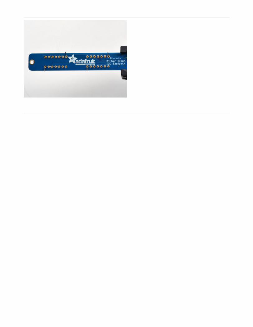
Bi-Color 24 BargraphThis version of the LED backpack is designed for these bright and colorful bi-color bargraph modules. Each modulehas 12 red and 12 green LEDs inside, for a total of 24 LEDs controlled as a 1x12 matrix. We put two modules on eachbackpack for a 24-bar long bargraph (48 total LEDs).
This backpack solves the annoyance of using lots of pins or a bunch of chips by having an I2C constant-current matrixcontroller sit neatly on the back of the PCB. The controller chip takes care of everything, drawing all 48 LEDs in thebackground. All you have to do is write data to it using the 2-pin I2C interface. There are three address select pins soyou can select one of 8 addresses to control up to 8 of these on a single 2-pin I2C bus (as well as whatever other I2Cchips or sensors you like). The driver chip can 'dim' the entire display from 1/16 brightness up to full brightness in 1/16thsteps. It cannot dim individual LEDs, only the entire display at once.
Attaching the bar-graph modules
Remove the parts from packaging and place the LED bargraphs over the outlines on the top of the PCB.
The bargraph must be soldered on the correct orientation or it will not work! Check for the side of the bargraph thathas printing on it. Then look for the outline on the PCB that has "Text on this side" marked!
Do not solder the matrix onto the back of the PCB, it won't work either!
Pay close attention to the instructions for positioning the bargraphs. They must be oriented correctly to workand is almost impossible to remove them once soldered to the backpack!
© Adafruit Industries https://learn.adafruit.com/adafruit-led-backpack Page 50 of 74

To keep the two bargraphs lined up nicely, you can use a little masking or scotch tape on the bargraph modules, tapethem so they are in a straight line. There is a little play during soldering so if you don't do this the two modules may notbe in a perfect line.
© Adafruit Industries https://learn.adafruit.com/adafruit-led-backpack Page 51 of 74
Turn over the PCB and bend opposite-corner pins of the
modules out so that the modules are fixed in place
against the PCB. Now is a good time to do a last check
that you oriented the modules the right way!
Solder all the module pins in!
© Adafruit Industries https://learn.adafruit.com/adafruit-led-backpack Page 52 of 74
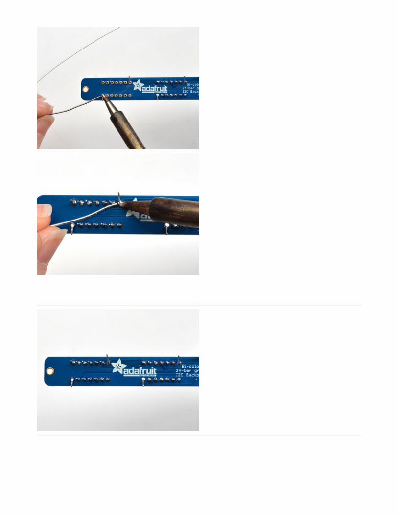
OK nice work!
© Adafruit Industries https://learn.adafruit.com/adafruit-led-backpack Page 53 of 74
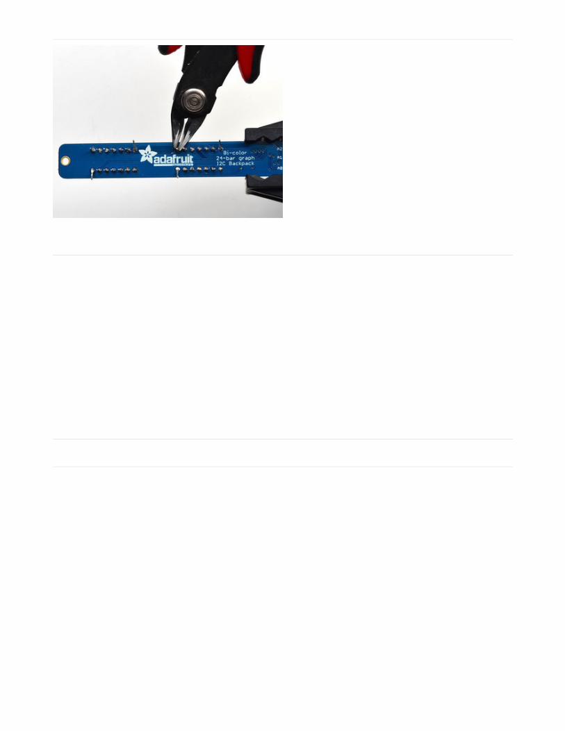
Once soldered, clip each pin. They're quite short and the
pins are thicker than usual, so do this over/inside a trash
bin so that the pins don't fly off and it you or your pets.
Everything should be neat and clipped, you're done!
Soldering on breadboard pins
This is an optional step - you only need to do this step if you're planning on using the bargraph in a breadboard.Chances are you may want to solder wires directly to the pads instead, so you can mount the bargraph elsewhere.Anyhow, skip this step if its not for you!
© Adafruit Industries https://learn.adafruit.com/adafruit-led-backpack Page 54 of 74
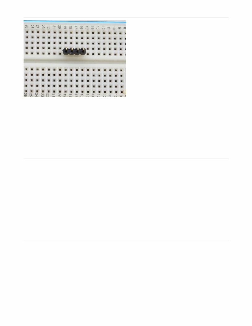
Break off a piece of male header, 4 pins long. Plug the
long ends into a solderless breadboard.
Place the PCB on top. you may need to support it a little
since its quite long.
© Adafruit Industries https://learn.adafruit.com/adafruit-led-backpack Page 55 of 74
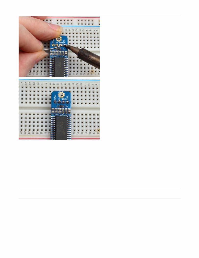
Solder these 4 pins too, since you're good at it now this
should be easy.
Bi-Color Bargraph LED Backpack Wiring & FirmwareWe wrote a basic library to help you work with the bi-color bargraph backpack. The library is written for the Arduinoand will work with any Arduino as it just uses the I2C pins. The code is very portable and can be easily adapted to anyI2C-capable micro.
Wiring to the bargraph is really easy
Connect SCL to the I2C clock - on Arduino UNO thats Analog #5, on the Leonardo its Digital #3, on the Mega itsdigital #21Connect SDA to the I2C data - on Arduino UNO thats Analog #4, on the Leonardo its Digital #2, on the Mega its
© Adafruit Industries https://learn.adafruit.com/adafruit-led-backpack Page 56 of 74

digital #20Connect GND to common groundConnect VCC to power - 5V is best but 3V also seems to work for 3V microcontrollers.
Next, download the Adafruit LED Backpack library from github . To download click the DOWNLOADS button in the topright corner, rename the uncompressed folder Adafruit_LEDBackpack. Check that the Adafruit_LEDBackpack foldercontains Adafruit_LEDBackpack.cpp and Adafruit_LEDBackpack.h Place the Adafruit_LEDBackpack library folderyour arduinosketchfolder/libraries/ folder. You may need to create the libraries subfolder if its your first library. You'llalso need to download the Adafruit GFX library that provides the graphics drawing routines. Restart the IDE.
Once you've restarted you should be able to select the File->Examples->Adafruit_LEDBackpack->bargraph24 examplesketch. Upload it to your Arduino as usual. You should see a basic test program that tests all the LEDs with differentcolors
© Adafruit Industries https://learn.adafruit.com/adafruit-led-backpack Page 57 of 74

Using the library interface is very easy. Start by creating the object with
Adafruit_24bargraph bar = Adafruit_24bargraph();
you can name it whatever you want, not just bar
Then initialize it with
bar.begin(0x70); // pass in the address
You can init with any address from 0x70 to 0x77, just make sure you solder in the matching solder jumpers!
Finally, write to the bargraph with
bar.setBar(lednumber, ledcolor);
Where lednumber is 0 thru 23. ledcolor can be LED_RED, LED_YELLOW, LED_GREEN or LED_OFF
The drawing routines only change the display memory kept by the Arduino. Don't forget to call bar.writeDisplay() afterdrawing to 'save' the memory out to the matrix via I2C.
There are also a few small routines that are special to the matrix:
setBrightness(brightness)- will let you change the overall brightness of the entire display. 0 is least bright, 15 isbrightest and is what is initialized by the display when you startblinkRate(rate) - You can blink the entire display. 0 is no blinking. 1, 2 or 3 is for display blinking.
© Adafruit Industries https://learn.adafruit.com/adafruit-led-backpack Page 58 of 74

Connecting Multiple BackpacksThe coolest part about the I2C backpacks is that you can connect more than one using just the same 2 pins. Thisopens possibilities for all kinds of multi-display projects.
For a project that shows this is practice, check out this page on animating multiple LED backpacks
Wire it UpTo connect another backpack to your project, just wire it in parallel with the first one as in the diagram below.
© Adafruit Industries https://learn.adafruit.com/adafruit-led-backpack Page 59 of 74

Configure the AddressFor each backpack you add, you need to configure a different I2C address. You can keep adding backpacks in thesame way until you run out of addresses. See the next page for how to configure the address on your backpack.
© Adafruit Industries https://learn.adafruit.com/adafruit-led-backpack Page 60 of 74

Changing I2C AddressThe HT16K33 driver chip on these LED backpacks has a default I2C address of 0x70. Since each device on an I2C busmust have a unique address, its important to avoid collisions or you'll get a lot of strange responses from yourelectronic devices!
Luckily, the HT16K33 has 2 or 3 address adjust pins, so that the address can be changed! The mini 0.8" 8x8 matrixbackpack has 2 address adjust pins. The 1.2" 8x8, bi-color 8x8, bi-color bargraph and 4 x 7-segment backpacks have 3address adjust pins.
That means that you can set the backpacks to these addresses:
Mini 0.8" 8x8: 0x70, 0x71, 0x72, 0x73Small 1.2" 8x8: 0x70, 0x71, 0x72, 0x73, 0x74, 0x75, 0x76, 0x774 x 7-segment: 0x70, 0x71, 0x72, 0x73, 0x74, 0x75, 0x76, 0x77Bi-color 1.2" 8x8: 0x70, 0x71, 0x72, 0x73, 0x74, 0x75, 0x76, 0x77Bi-color 24-bargraph: 0x70, 0x71, 0x72, 0x73, 0x74, 0x75, 0x76, 0x77
You can mix-and-match matrices, as long as each one has a unique address!
Changing AddressesYou can change the address of a backpack very easily. Look on the back to find the two or three A0, A1 or A2 solderjumpers. Each one of these is used to hardcode in the address. If a jumper is shorted with solder, that sets the address.A0 sets the lowest bit with a value of 1, A1 sets the middle bit with a value of 2 and A2 sets the high bit with a value of4. The final address is 0x70 + A2 + A1 + A0. So for example if A2 is shorted and A0 is shorted, the address is 0x70 + 4 +1 = 0x75. If only A1 is shorted, the address is 0x70 + 2 = 0x72
A2 does not appear on the mini 0.8" 8x8 matrix, so you cannot set the address higher than 0x73
On the 1.2" 8x8 backpacks, the labels for A1 and A2 are swapped! Sorry about that!
© Adafruit Industries https://learn.adafruit.com/adafruit-led-backpack Page 61 of 74

Changing the address in your code
Once you've adjusted the address on the backpack, you'll also want to adjust the address in the code!For the Arduino library we wrote, its simple. For example, lets say you want to have two seven-segment matrices. Oneis set to address 0x70 and the other is set to 0x71. Find this code in the example
And change it to this:
That is, instantiate two matrix objects. Then one is called with begin(0x70) and the other is called with begin(0x71).Each one can be used individually. If you need more matrices, just instantiate more objects at the top and begin() eachone with the unique i2c address.
Adafruit_7segment matrix = Adafruit_7segment();
void setup() { Serial.begin(9600); Serial.println("7 Segment Backpack Test");
matrix.begin(0x70);}
Adafruit_7segment matrix1 = Adafruit_7segment();Adafruit_7segment matrix2 = Adafruit_7segment();
void setup() { Serial.begin(9600); Serial.println("Double 7 Segment Backpack Test");
matrix1.begin(0x70); matrix2.begin(0x71);}
© Adafruit Industries https://learn.adafruit.com/adafruit-led-backpack Page 62 of 74

© Adafruit Industries https://learn.adafruit.com/adafruit-led-backpack Page 63 of 74

F.A.Q.I want to use these modules with other non-Arduino, how can I port the code?
The best way to get up and running is to read the HT16K33 driver datasheet available athttp://learn.adafruit.com/adafruit-led-backpack/downloads - the backpacks all use this chip to do all the LED driving.You can cross-reference this document with the Arduino library code to adapt it to your platform. Anymicrocontroller that has I2C host support should be able to drive the backpacks but we only provide Arduinoexample code at this time
I'd like to use these backpacks with Python / Linux (e.g. a Raspberry Pi)
You're in luck! We have a full tutorial here that covers using the 7-segment and 8x8 matrices on a Pi with Pythoncode -> http://learn.adafruit.com/matrix-7-segment-led-backpack-with-the-raspberry-pi
I am having strange problems when combining Adafruit Motor Shield/Servo Shield (PCA9685 based) with theAdafruit LED Matrix/7Seg Backpacks
We are not sure why this occurs but there is an address collision even though the address are different! Set thebackpacks to address 0x71 or anything other than the default 0x70 to make the issue go away
© Adafruit Industries https://learn.adafruit.com/adafruit-led-backpack Page 64 of 74

DownloadsSoftware
Download the Adafruit LED Backpack library from github - This code provides support for the mini 8x8, 1.2" 8x8, 7-segment, bargraph, alphanumeric and bicolor LED matrix backpacks.
To download click the ZIP download button, rename the uncompressed folder Adafruit_LEDBackpack. Check that theAdafruit_LEDBackpack folder contains Adafruit_LEDBackpack.cpp and Adafruit_LEDBackpack.h Place theAdafruit_LEDBackpack library folder your arduinosketchfolder/libraries/ folder.
You may need to create the libraries subfolder if its your first library.
You'll also need to download the Adafruit GFX library - its not actually used for the 7-segment, its only for the matrixbackpacks but its still required. Install just like the library above. Restart the IDE
Files
Fritzing objects in Adafruit Fritzing libraryEagleCAD PCB files for all backpacks in GitHub
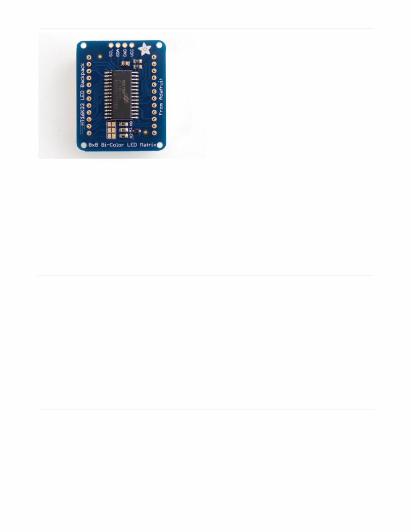
The backpacks all use the HT16K33 chip solely for LED driving - the mini 8x8's use the 24 pin version and theothers use the 28 pin vesion
HT16K33 8x16 LED Backpack Breakout
Schematic & fabrication print
© Adafruit Industries https://learn.adafruit.com/adafruit-led-backpack Page 65 of 74

8x8 0.8" LED Backpack
© Adafruit Industries https://learn.adafruit.com/adafruit-led-backpack Page 66 of 74

8x8 1.2" LED Backpack
© Adafruit Industries https://learn.adafruit.com/adafruit-led-backpack Page 67 of 74

8x8 1.2" Bi-Color LED Backpack
© Adafruit Industries https://learn.adafruit.com/adafruit-led-backpack Page 68 of 74

16x8 1.2" LED Backpacks
© Adafruit Industries https://learn.adafruit.com/adafruit-led-backpack Page 69 of 74

Quad 0.56" 7-Segment
© Adafruit Industries https://learn.adafruit.com/adafruit-led-backpack Page 70 of 74

Quad 0.54" 14-segment Alphanumeric
Quad 1.2" 7-Segment
© Adafruit Industries https://learn.adafruit.com/adafruit-led-backpack Page 71 of 74

Bicolor 24-Bargraph
© Adafruit Industries https://learn.adafruit.com/adafruit-led-backpack Page 72 of 74

© Adafruit Industries https://learn.adafruit.com/adafruit-led-backpack Page 73 of 74