Adafruit Feather HUZZAH ESP8266 · This is the Adafruit Feather HUZZAH ESP8266 - our take on an...
54
Adafruit Feather HUZZAH ESP8266 Created by lady ada Last updated on 2020-03-02 09:25:49 PM UTC
Transcript of Adafruit Feather HUZZAH ESP8266 · This is the Adafruit Feather HUZZAH ESP8266 - our take on an...

Adafruit Feather HUZZAH ESP8266Created by lady ada
Last updated on 2020-03-02 09:25:49 PM UTC

Overview
Feather is the new development board from Adafruit, and like it's namesake it is thin, light, and lets you fly! Wedesigned Feather to be a new standard for portable microcontroller cores.
This is the Adafruit Feather HUZZAH ESP8266 - our take on an 'all-in-one' ESP8226 WiFi development board with builtin USB and battery charging. Its an ESP8266 WiFi module with all the extras you need, ready to rock! We have otherboards in the Feather family, check'em out here (https://adafru.it/jAQ).
© Adafruit Industries https://learn.adafruit.com/adafruit-feather-huzzah-esp8266 Page 4 of 55

At the Feather HUZZAH's heart is an ESP8266 WiFi microcontroller clocked at 80 MHz and at 3.3V logic. Thismicrocontroller contains a Tensilica chip core as well as a full WiFi stack. You can progam the microcontroller using theArduino IDE for an easy-to-run Internet of Things core. We wired up a USB-Serial chip that can upload code at ablistering 921600 baud for fast development time. It also has auto-reset so no noodling with pins and reset buttonpressings.
To make it easy to use for portable projects, we added a connector for any of our 3.7V Lithium polymer batteries andbuilt in battery charging. You don't need a battery, it will run just fine straight from the micro USB connector. But, if youdo have a battery, you can take it on the go, then plug in the USB to recharge. The Feather will automatically switchover to USB power when its available.
© Adafruit Industries https://learn.adafruit.com/adafruit-feather-huzzah-esp8266 Page 5 of 55

Here's some handy specs!
Measures 2.0" x 0.9" x 0.28" (51mm x 23mm x 8mm) without headers soldered inLight as a (large?) feather - 6 gramsESP8266 @ 80MHz or 160 MHz with 3.3V logic/power4MB of FLASH (32 MBit)3.3V regulator with 500mA peak current outputCP2104 USB-Serial converter onboard with 921600 max baudrate for uploadingAuto-reset support for getting into bootload mode before firmware upload9 GPIO pins - can also be used as I2C and SPI1 x analog inputs 1.0V maxBuilt in 100mA lipoly charger with charging status indicator LEDPin #0 red LED for general purpose blinking. Pin #2 blue LED for bootloading debug & general purpose blinkingPower/enable pin4 mounting holesReset button
© Adafruit Industries https://learn.adafruit.com/adafruit-feather-huzzah-esp8266 Page 6 of 55

Comes fully assembled and tested, with a USB interface that lets you quickly use it with the Arduino IDE or NodeMCULua. (It comes preprogrammed with the Lua interpretter) We also toss in some header so you can solder it in and pluginto a solderless breadboard. Lipoly battery and USB cable not included (but we do have lots of options in the shop ifyou'd like!)
© Adafruit Industries https://learn.adafruit.com/adafruit-feather-huzzah-esp8266 Page 7 of 55

Pinouts
© Adafruit Industries https://learn.adafruit.com/adafruit-feather-huzzah-esp8266 Page 8 of 55

Power Pins
GND - this is the common ground for all power and logicBAT - this is the positive voltage to/from the JST jack for the optional Lipoly batteryUSB - this is the positive voltage to/from the micro USB jack if connectedEN - this is the 3.3V regulator's enable pin. It's pulled up, so connect to ground to disable the 3.3V regulator3V - this is the output from the 3.3V regulator, it can supply 500mA peak (try to keep your current draw under250mA so you have plenty for the ESP8266's power requirements!)
Logic pins
This is the general purpose I/O pin set for the microcontroller. All logic is 3.3V
Serial pins
RX and TX are the serial control and bootloading pins, and are how you will spend most of your time communicatingwith the ESP module
The ESP8266 runs on 3.3V power and logic, and unless otherwise specified, GPIO pins are not 5V safe! The analog pin is also 1.0V max!�
© Adafruit Industries https://learn.adafruit.com/adafruit-feather-huzzah-esp8266 Page 9 of 55

The TX pin is the output from the module and is 3.3V logic.
The RX pin is the input into the module and is 5V compliant (there is a level shifter on this pin)
These are connected through to the CP2104 USB-to-Serial converter so they should not be connected to or usedunless you're super sure you want to because you will also be getting the USB traffic on these!
I2C & SPI pins
You can use the ESP8266 to control I2C and SPI devices, sensors, outputs, etc. While this is done by 'bitbanging', itworks quite well and the ESP8266 is fast enough to match 'Arduino level' speeds.
In theory you can use any pins for I2C and SPI but to make it easier for people using existing Arduino code, libraries,sketches we set up the following:
I2C SDA = GPIO #4 (default)I2C SCL = GPIO #5 (default)
If you want, you can connect to I2C devices using other 2 pins in the Arduino IDE, by calling Wire.pins(sda, scl)before any other Wire code is called (so, do this at the begining of setup() for example
Likewise, you can use SPI on any pins but if you end up using 'hardware SPI' you will want to use the following:
SPI SCK = GPIO #14 (default)SPI MOSI = GPIO #13 (default)SPI MISO = GPIO #12 (default)
GPIO pins
© Adafruit Industries https://learn.adafruit.com/adafruit-feather-huzzah-esp8266 Page 10 of 55

This breakout has 9 GPIO: #0, #2, #4, #5, #12, #13, #14, #15, #16 arranged at the top edge of the Feather PCB
All GPIO are 3.3V logic level in and out, and are not 5V compatible. Read the full spec sheet (https://adafru.it/f1E) tolearn more about the GPIO pin limits, but be aware the maximum current drawn per pin is 12mA.
These pins are general purpose and can be used for any sort of input or output. Most also have the ability to turn on aninternal pullup. Many have special functionality:
GPIO #0, which does not have an internal pullup, and is also connected a red LED. This pin is used by the ESP8266 todetermine when to boot into the bootloader. If the pin is held low during power-up it will start bootloading! That said,you can always use it as an output, and blink the red LED - note the LED is reverse wired so setting the pin LOW willturn the LED on.
GPIO #2, is also used to detect boot-mode. It also is connected to the blue LED that is near the WiFi antenna. It has apullup resistor connected to it, and you can use it as any output (like #0) and blink the blue LED.
GPIO #15, is also used to detect boot-mode. It has a pulldown resistor connected to it, make sure this pin isn't pulledhigh on startup. You can always just use it as an output
GPIO #16 can be used to wake up out of deep-sleep mode, you'll need to connect it to the RESET pin
Also note that GPIO #12/13/14 are the same as the SCK/MOSI/MISO 'SPI' pins!
Analog Pins
There is also a single analog input pin called A. This pin has a ~1.0V maximum voltage, so if you have an analogvoltage you want to read that is higher, it will have to be divided down to 0 - 1.0V range
© Adafruit Industries https://learn.adafruit.com/adafruit-feather-huzzah-esp8266 Page 11 of 55

Other control pins
We have a few other pins for controlling the ESP8266
RST - this is the reset pin for the ESP8266, pulled high by default. When pulled down to ground momentarily itwill reset the ESP8266 system. This pin is 3.3V logic onlyEN (CH_PD) - This is the enable pin for the ESP8266, pulled high by default. When pulled down to groundmomentarily it will reset the ESP8266 system. This pin is 3.3V logic only
NC Pins
The rest of the pins are labeled NC which means Not Connected - they are not connected to anything and are there asplaceholders only, to maintain physical compatibility with the other boards in the Feather line!
© Adafruit Industries https://learn.adafruit.com/adafruit-feather-huzzah-esp8266 Page 12 of 55

Assembly
We ship Feathers fully tested but without headers attached - this gives you the most flexibility on choosing how to useand configure your Feather
Header Options!
Before you go gung-ho on soldering, there's a few options to consider!
The first option is soldering in plain male headers, this
lets you plug in the Feather into a solderless breadboard
© Adafruit Industries https://learn.adafruit.com/adafruit-feather-huzzah-esp8266 Page 13 of 55

Another option is to go with socket female headers. This
won't let you plug the Feather into a breadboard but it
will let you attach featherwings very easily
© Adafruit Industries https://learn.adafruit.com/adafruit-feather-huzzah-esp8266 Page 14 of 55

We also have 'slim' versions of the female headers, that
are a little shorter and give a more compact shape
© Adafruit Industries https://learn.adafruit.com/adafruit-feather-huzzah-esp8266 Page 15 of 55

Finally, there's the "Stacking Header" option. This one is
sort of the best-of-both-worlds. You get the ability to
plug into a solderless breadboard and plug a
featherwing on top. But its a little bulky
Soldering in Plain Headers
Prepare the header strip:Cut the strip to length if necessary. It will be easier to
solder if you insert it into a breadboard - long pins down
© Adafruit Industries https://learn.adafruit.com/adafruit-feather-huzzah-esp8266 Page 16 of 55

Add the breakout board:Place the breakout board over the pins so that the short
pins poke through the breakout pads
And Solder!Be sure to solder all pins for reliable electrical contact.
(For tips on soldering, be sure to check out our Guide to
Excellent Soldering (https://adafru.it/aTk)).
© Adafruit Industries https://learn.adafruit.com/adafruit-feather-huzzah-esp8266 Page 17 of 55

Solder the other strip as well.
© Adafruit Industries https://learn.adafruit.com/adafruit-feather-huzzah-esp8266 Page 18 of 55

You're done! Check your solder joints visually and
continue onto the next steps
Soldering on Female Header
Tape In PlaceFor sockets you'll want to tape them in place so when
you flip over the board they don't fall out
© Adafruit Industries https://learn.adafruit.com/adafruit-feather-huzzah-esp8266 Page 19 of 55

Flip & Tack SolderAfter flipping over, solder one or two points on each
strip, to 'tack' the header in place
© Adafruit Industries https://learn.adafruit.com/adafruit-feather-huzzah-esp8266 Page 20 of 55

And Solder!Be sure to solder all pins for reliable electrical contact.
(For tips on soldering, be sure to check out our Guide to
Excellent Soldering (https://adafru.it/aTk)).
© Adafruit Industries https://learn.adafruit.com/adafruit-feather-huzzah-esp8266 Page 21 of 55

You're done! Check your solder joints visually and
continue onto the next steps
© Adafruit Industries https://learn.adafruit.com/adafruit-feather-huzzah-esp8266 Page 22 of 55

PowerManagement
Battery + USB Power
We wanted to make the Feather HUZZAH easy to power both when connected to a computer as well as via battery.There's two ways to power a Feather. You can connect with a MicroUSB cable (just plug into the jack) and the Featherwill regulate the 5V USB down to 3.3V. You can also connect a 4.2/3.7V Lithium Polymer (Lipo/Lipoly) or Lithium Ion(LiIon) battery to the JST jack. This will let the Feather run on a rechargable battery. When the USB power is powered,it will automatically switch over to USB for power, as well as start charging the battery (if attached) at 100mA. Thishappens 'hotswap' style so you can always keep the LiPoly connected as a 'backup' power that will only get usedwhen USB power is lost.
Don't power the Huzzah ESP8266 with a CanaKit 5V power supply, these power supplies have been destroying the CP2104 chip.�
The JST connector polarity is matched to Adafruit LiPoly batteries. Using wrong polarity batteries can destroy your Feather�
© Adafruit Industries https://learn.adafruit.com/adafruit-feather-huzzah-esp8266 Page 23 of 55

The above shows the Micro USB jack (left), Lipoly JST jack (top left), as well as the 3.3V regulator and changeoverdiode (just to the right of the JST jack) and the Lipoly charging circuitry (right below the regulator).
There's also a CHG LED next to the USB jack, which will light up while the battery is charging. This LED might alsoflicker if the battery is not connected.
Power supplies
You have a lot of power supply options here! We bring out the BAT pin, which is tied to the lipoly JST connector, aswell as USB which is the +5V from USB if connected. We also have the 3V pin which has the output from the 3.3Vregulator. We use a 500mA peak low-dropout regulator. While you can get 500mA from it, you can't do it continuouslyfrom 5V as it will overheat the regulator. We use this to power the ESP8266 which can draw spikes of 250+mA(although its not continuous).
You should be able to budget about 250mA current available from the regulator, which will leave plenty for the WiFimodule.
Measuring Battery
If you're running off of a battery, chances are you wanna know what the voltage is at! That way you can tell when thebattery needs recharging. Lipoly batteries are 'maxed out' at 4.2V and stick around 3.7V for much of the battery life,then slowly sink down to 3.2V or so before the protection circuitry cuts it off. By measuring the voltage you can quickly
© Adafruit Industries https://learn.adafruit.com/adafruit-feather-huzzah-esp8266 Page 24 of 55

tell when you're heading below 3.7V
Since the ESP8266 does not have multiple ADC pins, we didn't want to 'sacrifice' one for Lipoly battery monitoring.However we do have a tutorial that mentions how to do it, using two resistors. You can check out the wiring diagramhere (use the VBat pin to measure) (https://adafru.it/jCY) and the code here (https://adafru.it/jCZ).
ENable pin
If you'd like to turn off the 3.3V regulator, you can do that with the EN(able) pin. Simply tie this pin to Ground and it willdisable the 3V regulator. The BAT and USB pins will still be powered
Alternative Power Options
The two primary ways for powering a feather are a 3.7/4.2V LiPo battery plugged into the JST port or a USB powercable.
If you need other ways to power the Feather, here's what we recommend:
For permanent installations, a 5V 1A USB wall adapter (https://adafru.it/duP) will let you plug in a USB cable forreliable powerFor mobile use, where you don't want a LiPoly, use a USB battery pack! (https://adafru.it/e2q)If you have a higher voltage power supply, use a 5V buck converter (https://adafru.it/DHs) and wire it to a USBcable's 5V and GND input (https://adafru.it/DHu)
Here's what you cannot do:
Do not use alkaline or NiMH batteries and connect to the battery port - this will destroy the LiPoly charger andthere's no way to disable the chargerDo not use 7.4V RC batteries on the battery port - this will destroy the board
The Feather is not designed for external power supplies - this is a design decision to make the board compact and lowcost. It is not recommended, but technically possible:
Connect an external 3.3V power supply to the 3V and GND pins. Not recommended, this may cause unexpectedbehavior and the EN pin will no longer. Also this doesn't provide power on BAT or USB and someFeathers/Wings use those pins for high current usages. You may end up damaging your Feather.Connect an external 5V power supply to the USB and GND pins. Not recommended, this may cause unexpected
© Adafruit Industries https://learn.adafruit.com/adafruit-feather-huzzah-esp8266 Page 25 of 55

behavior when plugging in the USB port because you will be back-powering the USB port, which could confuseor damage your computer.
© Adafruit Industries https://learn.adafruit.com/adafruit-feather-huzzah-esp8266 Page 26 of 55

Using NodeMCULua
Each Feather HUZZAH ESP8266 breakout comes pre-programmed with NodeMCU's Lua interpreter. As of this writing,we ship with NodeMCU 0.9.5 build 20150318 powered by Lua 5.1.4 but it may be more recent
Lua is still a work in progress, so we strongly recommend visiting NodeMCU and updating your Lua version to the verylatest as they have the ability to make you the latest continuous build (https://adafru.it/wAq). Then follow their guide onhow to update Lua! (https://adafru.it/wAr)
The Lua interpreter runs on the ESP8266 and you can type in commands and read out the results over serial. In orderto upload code to the ESP8266 and use the serial console, connect any data-capable micro USB cable to the FeatherHUZZAH and the other side to your computer's USB port. Install the required CP2104 USB driver to have theCOM/Serial port appear properly (https://adafru.it/jCs)
Don't forget to visit esp8266.com for the latest and greatest in ESP8266 news, software andgossip! (https://adafru.it/f1F)
Open up serial console
Next up, on your computer, use a serial console program such as CoolTerm (Mac) or Putty (Windows) or screen (linux).Teraterm seems to dislike the initial 74400bps data stream from the ESP8266 so you can try it but you'll possibly needto reset the terminal software.
Connect up to the COM or Serial port used by your cable, at 9600 BaudMake sure you have turned off any hardware handshake or flow controlPutty isn't good with pasting code in, so you may not be able to copy-n-paste! Also make sure you have line endings set to CRLF "\r\n"
Use any serial console program you like, we just happen to be used to Putty!
Don't forget to install the USB driver for the CP2104 USB-to-Serial chip!�
© Adafruit Industries https://learn.adafruit.com/adafruit-feather-huzzah-esp8266 Page 27 of 55

Once the terminal software is connected, click the Reset button on the Feather HUZZAH ESP8266 board to reset it andhave it print out the welcome message:
If you don't get this message, first check that the red/blue leds flickered when you press the reset button. If they didnt,make sure you've got the right baud rate selected in the software (9600)
Hello world!
Ok we can now turn on an LED. There is a red LED on each board, connected to GPIO #0
NodeMCU Lua's pinouts are not the same as the Arduino/gcc pinouts. We print the Arduino pinouts on the board so watch out!�
© Adafruit Industries https://learn.adafruit.com/adafruit-feather-huzzah-esp8266 Page 28 of 55
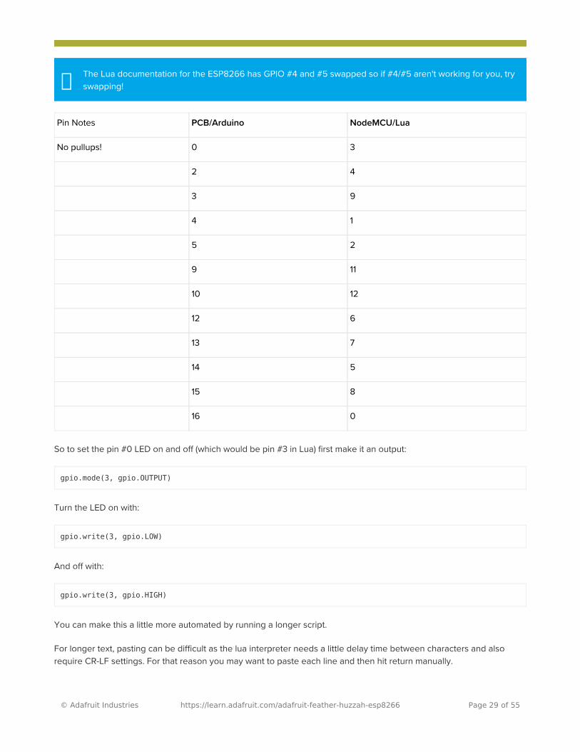
So to set the pin #0 LED on and off (which would be pin #3 in Lua) first make it an output:
gpio.mode(3, gpio.OUTPUT)
Turn the LED on with:
gpio.write(3, gpio.LOW)
And off with:
gpio.write(3, gpio.HIGH)
You can make this a little more automated by running a longer script.
For longer text, pasting can be difficult as the lua interpreter needs a little delay time between characters and alsorequire CR-LF settings. For that reason you may want to paste each line and then hit return manually.
The Lua documentation for the ESP8266 has GPIO #4 and #5 swapped so if #4/#5 aren't working for you, try swapping!�
Pin Notes PCB/Arduino NodeMCU/Lua
No pullups! 0 3
2 4
3 9
4 1
5 2
9 11
10 12
12 6
13 7
14 5
15 8
16 0
© Adafruit Industries https://learn.adafruit.com/adafruit-feather-huzzah-esp8266 Page 29 of 55

while 1 do gpio.write(3, gpio.HIGH) tmr.delay(1000000) -- wait 1,000,000 us = 1 second gpio.write(3, gpio.LOW) tmr.delay(1000000) -- wait 1,000,000 us = 1 secondend
The LED will now be blinking on and off.
Note that since its in a loop, its not possible to get it to stop via the interpreter. To stop it, click the Reset button again!
This code halts the processor during the tmr.delay, a smarter way to blink an LED is to use the timer capability to set offthe LED control (code from here (https://adafru.it/wGA))
-- Pin definition local pin = 3local status = gpio.LOWlocal duration = 1000 -- 1 second duration for timer
-- Initialising pingpio.mode(pin, gpio.OUTPUT)gpio.write(pin, status)
-- Create an intervaltmr.alarm(0, duration, 1, function () if status == gpio.LOW then status = gpio.HIGH else status = gpio.LOW end
gpio.write(pin, status)end)
Scanning & Connecting to WiFi
We'll continue with a quick demo of scanning for WiFi and connecting.
Once you're back at the Lua prompt, set the ESP8266 into WiFi Client mode with
wifi.setmode(wifi.STATION)
Then you can run the scanner and have it print out the available AP's
-- print ap listfunction listap(t) for k,v in pairs(t) do print(k.." : "..v) endendwifi.sta.getap(listap)
© Adafruit Industries https://learn.adafruit.com/adafruit-feather-huzzah-esp8266 Page 30 of 55

or for more detail...
-- print ap listfunction listap(t) for ssid,v in pairs(t) do authmode, rssi, bssid, channel = string.match(v, "(%d),(-?%d+),(%x%x:%x%x:%x%x:%x%x:%x%x:%x%x),(%d+)") print(ssid,authmode,rssi,bssid,channel) endend wifi.sta.getap(listap)
We can connect to the access point with wifi.sta.config and wifi.sta.connect - it will take a second or two to completethe connection, you can query the module to ask the status with wifi.sta.status() - when you get a 5 it means theconnection is completed and DHCP successful
wifi.sta.config("accesspointname","yourpassword")wifi.sta.connect()tmr.delay(1000000) -- wait 1,000,000 us = 1 secondprint(wifi.sta.status())print(wifi.sta.getip())
WebClient example
Once you're got the IP address you can connect to adafruit, for example, and read a webpage and print it out:
sk=net.createConnection(net.TCP, 0)sk:on("receive", function(sck, c) print(c) end )sk:connect(80,"207.58.139.247")sk:send("GET /testwifi/index.html HTTP/1.1\r\nHost: www.adafruit.com\r\nConnection: keep-alive\r\nAccept: */*\r\n\r\n")
You can also have the module do DNS for you, just give it the hostname instead of IP address:
sk=net.createConnection(net.TCP, 0)sk:on("receive", function(sck, c) print(c) end )sk:connect(80,"www.adafruit.com")sk:send("GET /testwifi/index.html HTTP/1.1\r\nHost: www.adafruit.com\r\nConnection: keep-alive\r\nAccept: */*\r\n\r\n")
This is just a light overview of testing out your HUZZAH ESP breakout! For much more, check out NodeMCU'sdocumentation page https://nodemcu.readthedocs.io/ (https://adafru.it/wGB) for the details on what functions areavailable to you, as well as http://www.lua.org (https://adafru.it/f1N) to learn more about the Lua scripting language
© Adafruit Industries https://learn.adafruit.com/adafruit-feather-huzzah-esp8266 Page 31 of 55

Using Arduino IDE
While the Feather HUZZAH ESP8266 comes pre-programmed with NodeMCU's Lua interpretter, you don't have to useit! Instead, you can use the Arduino IDE which may be more familar. This will write directly to the firmware, erasing theNodeMCU firmware, so if you want to go back to Lua, use the flasher to re-install it (https://adafru.it/f1O)
Don't forget to visit esp8266.com for the latest and greatest in ESP8266 news, software andgossip! (https://adafru.it/f1F)
In order to upload code to the ESP8266 and use the serial console, connect any data-capable micro USB cable to theFeather HUZZAH and the other side to your computer's USB port.
Don't forget you will also need to install the SiLabs CP2104 Driver:
https://adafru.it/vrf
https://adafru.it/vrf
On Mac OS 10.13 and higher, in addition to installing, you will have to give the CP2104 kernel driver permission to load.You can find out if you need to give additional permission by visiting your Security & Privacy settings systempreferences screen after installing and looking for the message that says, 'System software from developer "SiLabs"was blocked from loading', like in the picture below.
© Adafruit Industries https://learn.adafruit.com/adafruit-feather-huzzah-esp8266 Page 32 of 55

To allow the driver to load, click the lock icon, enter your password, and click "Allow" next to the warning message.After that, you may have to restart your computer before following the steps below and connecting to your Huzzah inthe Arduino app.
https://adafru.it/ymF
https://adafru.it/ymF
Install the Arduino IDE 1.6.8 or greater
Download Arduino IDE from Arduino.cc (1.6.8 or greater) (https://adafru.it/f1P) from Arduino.cc
The latest is usually the best
Install the ESP8266 Board Package
Enter http://arduino.esp8266.com/stable/package_esp8266com_index.json into Additional Board Manager URLs field
in the Arduino v1.6.4+ preferences.
If you are using Mac OS 10.12.6 (Sierra) and you cannot upload with the latest Mac OS VCP driver, please try the legacy v4 driver below. Note you will need to uninstall the v5 driver using uninstall.sh (in the driver package)
�
© Adafruit Industries https://learn.adafruit.com/adafruit-feather-huzzah-esp8266 Page 33 of 55

Visit our guide for how to add new boards to the Arduino 1.6.4+ IDE for more info about adding third partyboards (https://adafru.it/f7X).
Next, use the Board manager to install the ESP8266 package.
After the install process, you should see that esp8266 package is marked INSTALLED. Close the Boards Managerwindow once the install process has completed.
If you want to use this board with Adafruit IO Arduino - make sure you're on version 2.5.1 or ABOVE.�
© Adafruit Industries https://learn.adafruit.com/adafruit-feather-huzzah-esp8266 Page 34 of 55

Setup ESP8266 Support
When you've restarted, select Adafruit Feather HUZZAH ESP8266 from the Tools->Board dropdown
80 MHz as the CPU frequency
You can keep the Flash Sizeat "4M (3M SPIFFS)
For Upload Speed, select 115200 baud (You can also try faster baud rates, we were able to upload at a blistering921600 baud but sometimes it fails & you have to retry)
© Adafruit Industries https://learn.adafruit.com/adafruit-feather-huzzah-esp8266 Page 35 of 55

The matching COM port for your FTDI or USB-Serial cable
On a mac, you should look for the "SLAB_USBtoUART" port
Blink Test
We'll begin with the simple blink test
Enter this into the sketch window (and save since you'll have to)
void setup() { pinMode(0, OUTPUT);}
void loop() { digitalWrite(0, HIGH); delay(500); digitalWrite(0, LOW); delay(500);}
© Adafruit Industries https://learn.adafruit.com/adafruit-feather-huzzah-esp8266 Page 36 of 55

Now you can simply upload! The Feather HUZZAH has built in auto-reset that puts it into bootloading modeautomagically
The sketch will start immediately - you'll see the LED blinking. Hooray!
Connecting via WiFi
OK once you've got the LED blinking, lets go straight to the fun part, connecting to a webserver. Create a new sketchwith this code:
/* * Simple HTTP get webclient test */
#include <ESP8266WiFi.h>
const char* ssid = "yourssid";const char* password = "yourpassword";
const char* host = "wifitest.adafruit.com";
void setup() { Serial.begin(115200); delay(100);
// We start by connecting to a WiFi network
Serial.println(); Serial.println(); Serial.print("Connecting to "); Serial.println(ssid);
© Adafruit Industries https://learn.adafruit.com/adafruit-feather-huzzah-esp8266 Page 37 of 55

WiFi.begin(ssid, password); while (WiFi.status() != WL_CONNECTED) { delay(500); Serial.print("."); }
Serial.println(""); Serial.println("WiFi connected"); Serial.println("IP address: "); Serial.println(WiFi.localIP());}
int value = 0;
void loop() { delay(5000); ++value;
Serial.print("connecting to "); Serial.println(host); // Use WiFiClient class to create TCP connections WiFiClient client; const int httpPort = 80; if (!client.connect(host, httpPort)) { Serial.println("connection failed"); return; } // We now create a URI for the request String url = "/testwifi/index.html"; Serial.print("Requesting URL: "); Serial.println(url); // This will send the request to the server client.print(String("GET ") + url + " HTTP/1.1\r\n" + "Host: " + host + "\r\n" + "Connection: close\r\n\r\n"); delay(500); // Read all the lines of the reply from server and print them to Serial while(client.available()){ String line = client.readStringUntil('\r'); Serial.print(line); } Serial.println(); Serial.println("closing connection");}
Dont forget to update
const char* ssid = "yourssid";const char* password = "yourpassword";
to your access point and password, then upload the same way: get into bootload mode, then upload code via IDE
© Adafruit Industries https://learn.adafruit.com/adafruit-feather-huzzah-esp8266 Page 38 of 55

Open up the IDE serial console at 115200 baud to see the connection and webpage printout!
That's it, pretty easy!
This page was just to get you started and test out your module. For more information, check out the ESP8266 portgithub repository (https://adafru.it/eSH) for much more up-to-date documentation!
© Adafruit Industries https://learn.adafruit.com/adafruit-feather-huzzah-esp8266 Page 39 of 55

© Adafruit Industries https://learn.adafruit.com/adafruit-feather-huzzah-esp8266 Page 40 of 55

UsingMicroPython
Using MicroPython (https://adafru.it/DH1)
© Adafruit Industries https://learn.adafruit.com/adafruit-feather-huzzah-esp8266 Page 41 of 55

Downloads
Datasheets & Files
AP2112K-3.3V regulator onboard (https://adafru.it/mdb)CP2104 USB-to-Serial converter (https://adafru.it/jCr)EagleCAD PCB Files on GitHub (https://adafru.it/olc)Fritzing object in Adafruit Fritzing Library (https://adafru.it/c7M)3D Models on GitHub (https://adafru.it/GAz)
https://adafru.it/z4d
https://adafru.it/z4d
More info about the ESP8266
ESP8266 specification sheet (https://adafru.it/f1E)FCC test report (https://adafru.it/f1S) for the module used on this breakoutCE test report for the module used on this breakout (https://adafru.it/f1U)Huuuuge amount of information on http://www.esp8266.com/ (https://adafru.it/f1F) community forum!NodeMCU (Lua for ESP8266) webpage (https://adafru.it/f1G) with examples and documentation on the LuaframeworkArduino IDE support for ESP8266 (https://adafru.it/eSH)NodeMCU PyFlasher - a cross platform ESP flashing tool (https://adafru.it/Bg4)
Don't forget to visit esp8266.com for the latest and greatest in ESP8266 news, software andgossip! (https://adafru.it/f1F)
Schematic
© Adafruit Industries https://learn.adafruit.com/adafruit-feather-huzzah-esp8266 Page 42 of 55

Click to enlarge
Fabrication Print
Dimensions in inches
© Adafruit Industries https://learn.adafruit.com/adafruit-feather-huzzah-esp8266 Page 43 of 55

�
ESP8266 F.A.Q.
When I connect stuff to some of the pins, the Huzzah stops working. Whats up with that?
The ESP8266 uses some of the pins as 'boot mode' pins so on boot they must be set to certain values:
CH_PD (EN) should be always pulled high (it will disable the entire module if low)RST should be always pulled high (it will disable the entire module if low)GPIO 0 sets whether the bootloader is active, it must be pulled HIGH during power up/reset for the user programto run. If it's pulled LOW, it will activate the bootloader. The built-in red LED on #0 pulls it upGPIO 2 must be pulled high on power up/reset.GPIO 15 must be pulled low on power up/reset.
© Adafruit Industries https://learn.adafruit.com/adafruit-feather-huzzah-esp8266 Page 44 of 55

� My Huzzah board keeps crashing and resetting, whats up with that?
The most common reason for crashes is power failure. Make sure you're powering the Huzzah with a good ~5Vpower supply, and if you're using a USB-Serial cable, that it's plugged into the mainboard of your computer orthrough a powered hub!
© Adafruit Industries https://learn.adafruit.com/adafruit-feather-huzzah-esp8266 Page 45 of 55

� I can't seem to find the Serial port on my computer for the Feather HUZZAH?
Don't forget to install the CP2104 VCP drivers for your computer, they are required!
© Adafruit Industries https://learn.adafruit.com/adafruit-feather-huzzah-esp8266 Page 46 of 55

� I still can't seem to find the Serial port on my computer for the Feather Huzzah!
Many cheap electronics come with charge-only USB cables, which cause headaches later. Make sure you are usinga proper data/sync USB cable. If you find a cable that is charge-only (not data/sync also) throw it out so you don'thave the same problem again.
© Adafruit Industries https://learn.adafruit.com/adafruit-feather-huzzah-esp8266 Page 47 of 55

� So, I’m getting a 'no such file' error compiling for ESP8266 on my Mac
If your error message looks like this:
fork/exec /Users/xxxxxxx/Library/Arduino15/packages/esp8266/tools/xtensa-lx106-elf-gcc/1.20.0-26-gb404fb9-2/bin/xtensa-lx106-elf-g++: no such file or directoryError compiling.
To fix this problem, do this:
1. Open the Boards Manager in the Arduino IDE2. Uninstall the ESP8266 support3. go to your ~LIbrary folder (in the Finder, select "Go::Go to folder:, and enter ~Library ). Find the folder Arduino15.4. In the Arduino15 folder, go into packages, and delete the folder esp82665. Go back to the Arduino IDE, and install ESP8266 board support.6. Now go back to the Finder, and check that you have the xtensa-lx106-elf-g++ file in the
path Arduino15/packages/esp8266/tools/xtensa-lx106-elf-gcc/1.20.0-26-gb404fb9-2/bin/xtensa-lx106-elf-g++7. That's it!
© Adafruit Industries https://learn.adafruit.com/adafruit-feather-huzzah-esp8266 Page 48 of 55

� Whenever I start or reset the ESP8226 there's a bunch of "gibberish" on the Serial console
This is the ROM debug messages, it's transmitted at 74880 baud so you rarely see it in proper 'ascii output' - insteadusually it gets corrupted into a bunch of strange characters.
© Adafruit Industries https://learn.adafruit.com/adafruit-feather-huzzah-esp8266 Page 49 of 55

� I'm having difficulties uploading to the HUZZAH with the Arduino IDE
Make sure you're using a good quality USB/Serial cable. Install the official drivers for that cable too! We've alsonoticed that PL2303-based cables don't work on Macs for some reason. FTDI or CP210x based chipsets work best
© Adafruit Industries https://learn.adafruit.com/adafruit-feather-huzzah-esp8266 Page 50 of 55

� I tried that, but I'm still having difficulties uploading with the Arduino IDE
Sometimes, it helps to switch the board type to "Generic ESP8266 Module". Set the Reset Method to "nodemcu"
See this forum post
© Adafruit Industries https://learn.adafruit.com/adafruit-feather-huzzah-esp8266 Page 51 of 55

� I'm stuck in bootloader mode and can't upload
You say your led is stuck on dim and you get an error trying to upload? And you're sure your serial cable isconnected and working correctly? Well, here's a potential fix: Connect the GPIO0 pin to GND through a 220 ohmresistor. Leave it connected while you upload. You may have to try it a couple of times, but it should eventuallyupload and get the HUZZAH unstuck from bootload mode! You can then remove the resistor connection, and yourHUZZAH will be happy ever after!
(Note: you may also have to tie RST and EN (CH_PD) together to get this to work. Remove the connection once youhave the module programmed).
Thanks to forum user misslevania for the tip!
© Adafruit Industries https://learn.adafruit.com/adafruit-feather-huzzah-esp8266 Page 52 of 55

� I can't get Lua to respond to my commands
Make sure your terminal software is sending correct line endings! The default PuTTY settings may be wrong whentrying to talk to Lua on an ESP8266. Lua expects CRLF "\r\n" line endings, and apparently PuTTY defaults to just LF"\n"!
© Adafruit Industries https://learn.adafruit.com/adafruit-feather-huzzah-esp8266 Page 53 of 55

© Adafruit Industries https://learn.adafruit.com/adafruit-feather-huzzah-esp8266 Page 54 of 55

© Adafruit Industries Last Updated: 2020-03-02 09:25:49 PM UTC Page 55 of 55

Mouser Electronics
Authorized Distributor
Click to View Pricing, Inventory, Delivery & Lifecycle Information: Adafruit:
2821