
In re Morgan Stanley Mortgage Pass-Through Certificates Litigation 09-CV-02137-Order

AT>'AtteS 4Vt3
AD
TECHNICAL REPORT ARBRL-TR-02137
MECHANICS OF PENETRATION: ANALYSIS
AND EXPERIMENT
G- AH- 7
J^ TECHNICAL 1A'Zukas LIBRARY
February 1979
US ARMY ARMAMENT RESEARCH AND DEVELOPMENT COMMAND BALLISTIC RESEARCH LABORATORY ABERDEEN PROVING GROUND, MARYLAND
Approved for public release; distribution unlimited.

Destroy this report when it is no longer needed. Do not return it to the originator.
Secondary distribution of this report by originating or sponsoring activity is prohibited.
Additional copies of this report may be obtained from the National Technical Information Service, U.S. Department of Commerce, Springfield, Virginia 22161.
The findings in this report are not to be construed as an official Department of the Army position, unless so designated by other authorized docunents.
Tlie use of titide namea OP memufaoturera' namea in thin report Joea not oonatitute indoraement of any aoimeraial product.

UNCLASSIFIED SECURITY CLASSIFICATION OF THIS PAGE (When D«(« Bnlered)
REPORT DOCUMENTATION PAGE 1. REPORT NUMBER
TECHNICAL REPORT ARBRL-TR-02I37
2. GOVT ACCESSION NO.
4. TITLE (and Subtitle)
MECHANICS OF PENETRATION: ANALYSIS AND EXPERIMENT
7. AUTHORfa.)
G. H. Jonas J. A. Zukas
9. PERFORMING ORGANIZATION NAME AND ADDRESS US Army Ballistic Research Laboratory ATTN: DRDAR-BLT Aberdeen Proving Ground, MD 21005
READ INSTRUCTIONS BEFORE COMPLETING FORM
3. RECIPIENT'S CATALOG NUMBER
5. TYPE OF REPORT & PERIOD COVERED
Final
6. PERFORMING ORG. REPORT NUMBER
8. CONTRACT OR GRANT NUMBERfs;
]K CONTROLLING OFFICE NAME AND ADDRESS US Army Armament Research and Development Command US Army Ballistic Research Laboratory ATTN: DRDAR-BL Aberdeen Proving Ground. MD 21005 U. MONITORING AGENCY NAME & ADDRESSf//d/Her«n( from Controlling Olllce)
10. PROGRAM ELEMENT, PROJECT, TASK AREA & WORK UNIT NUMBERS
RDT5E 1L162618AH80
12. REPORT DATE
FEBRUARY 1979 13. NUMBER OF PAGES
64 IS. SECURITY CLASS, (ol thlm report)
UNCLASSIFIED 15a. DECLASSIFI CATION/DOWN GRADING
SCHEDULE
16. DISTRIBUTION STATEMENT (ol (Ma Reporf)
Approved for public release; distribution unlimited.
17. DISTRIBUTION STATEMENT (ot the abelract entered In Block 20, II dlllerent from Report)
18. SUPPLEMENTARY NOTES
19. KEY WORDS (Continue on reverse aide If neceamary and Identify by block number)
kinetic energy projectiles analytical methods numerical simulation
20, ABSTRACT (Cantbiua aa nraraa aide ft nacMaary and Identify by block number) (Irs)
This paper reviews available analytical methods for the study of kinetic energy
(inert) projectile-armor interactions at ordnance velocities (0.5-2 kms ). Particular emphasis is placed on three-dimensional numerical simulation of perforation and results of two-dimensional plane strain and three- dimensional finite element computations are compared with experimental results for impact situations leading to perforation and to ricochet. Problem areas and requirements for improved materials characterization are discussed.
DD/, FORM AN 73 1473 EDrTlOl* OF t MOV 65 IS OBSOLETE
UNCLASSIFIED SECURITY CLASStFICATIOK OF THIS PAGE (When Deta Entered)

TABLE OF CONTENTS
Page
I. INTRODUCTION ..... 9
II. ANALYTICAL MODELS 16
III. NUMERICAL METHODS 26
IV. OBLIQUE IMPACT SIMULATION 30
V. MATERIAL FAILURE CHARACTERIZATION. . , , . 41
REFERENCES .... ...... 49
DISTRIBUTION LIST . .,..,,,.. . 59

LIST OF ILLUSTRATIONS
Figure Page
1. Tungsten Alloy Rod Striking Thin Steel Plate 10
2. Example of Target Plugging Failure 11
3. Penetrator-Target Deformation Variation with Impact Velocity 12
4. Sectioned Target Plates and Residual Penetrators .... 13
5. Comparison of Plane Strain and Experimental Results at 12 us 33
6. Comparison of Plane Strain and Experimental Results at 25.6 ys 34
7. EPIC3 Prediction of Penetrator Deformation at 25 ys . . 35
8. EPIC3 Predicted Target and Penetrator Deformation at 25 ys 36
9. Comparison of Experimental, Three-Dimensional and Plane Strain Results at 25 ys 37
10. Schematic of Test Facility 38
11. Radiograph of Penetrator Ricochet 39
12. EPIC3 Predictions of Penetrator Deformation at 60 and 195 ys 40
13. Radiograph of Penetrator Fracture 42

LIST OF TABLES
Table Page
I. Impact Response of Materials 14
II. Penetrator and Target Characteristics 31
III. Material Properties 31

I. INTRODUCTION
The subject of penetration and perforation of solids has long been of interest in the military field and has recently commanded attention in a number of industrial applications, viz., the integrity of nuclear reactor pressure vessels and survivability of aircraft turbine blades struck by birds, Galileo was among the first to observe the difference between the static and dynamic behavior of metals. Serious research in analytical methods was undertaken about the time of World War II and continues to the present day; the current emphasis being on two- and three-dimensional numerical solutions to high velocity impact problems.
Penetration may be defined as the entrance of a missile into a target without completing its passage through the body. This involves either the embedding or rebound of the striker and the formation of a crater. Perforation, on the other hand, implies the complete piercing of a target by the projectile. Such processes tend to occur in a time frame of several to several hundred microseconds. The target can fail in a variety of ways, among them petalling, plugging, ductile failure and spall. Considerable deformation in the penetrator can also be expected. Some typical examples of penetrator-target interactions can be seen in Figures 1 through 4.
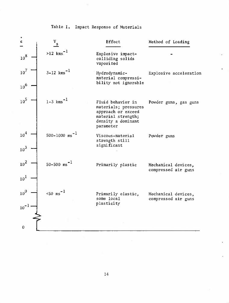
Since deformation is primarily determined by the velocity of impact- ing bodies, a short classification of impact processes as a function of striking velocity (and strain rate) seems appropriate (Table I). The range limitations should only be considered as reference points. In fact, the transitions are extraordinarily flexible since deformation processes depend on a long series of parameters in addition to impact velocity.
Penetration and perforation then are formidable physical problems. A rigorous analysis would require that one account for the geometry of the interacting bodies, elastic-plastic and shock wave propagation, hydrodynamic flow, finite strains and deflections, strain rate effects, work hardening, heating or frictional effects and the initiation and propagation of fracture. It is not surprising, therefore, that the bulk of the research in this area has been experimental in nature.
Analytical approaches have tended to fall into three categories:
- empirical or quasi-analytical: algebraic equations are formulated based on correlation with a large number of experimental data points and these are used to make predictions to guide further experiments. Such efforts are usually closely related to tests performed to discriminate between the performance characteristics of various materials, or structures for a particular design objective. In general, these efforts do not significantly advance our understanding of material behavior and processes and will not be considered in this paper. A variety of such models for penetration and ricochet have been reviewed by

■p 03
CD CD
■P CO
c ■H Xi H
bO
■H
•H u ■p co
o oi
X o
0) •p
bo B
E2
0)
3
• H IX
10

n
tg id IO CM
ii N
EH O I o o
> 5 o o
3
oj
M •H M
3
bO
H
o <u
o
■H
11

;-!., '■ .■■■■'-.■;. ■
\
0 U (J) Hi 7
to H * 0 tf) OD ^
h; CM
1 1- h a
0 (0 < s Q.
1 —
H
' l
0 Q liJ Oi K ^ rO 0 W - u. ii ii hi v> <n CD > CO
0) 10
0 ro (D ro
0
o ui
H
N, ■H. u H < * L (T 00
0 — >;■■:
0 II CO
CM 0 1—
OJ
0 10 CM
II It oe: CM U-
CM > i >
0
til 0 in Q
(T CM — 0 * — iL II II
III (n CO
m > 00
o o
>
u
o
a >
o
o 0) Q
+-> u bfl
f- i
N o
+-> rt *J a) 0)
(X
to
•H a.
12

Z s < 0
a ~ ^ o IJ
J
IS)
U O
0) (= 0)
•H
0)
1= a
0) bO U aj H
X) cu C o
•H +J o <u
CO
18 18 ■^f S a. w V <u "i gn h « ■« 3 i •s M a. •H To g UH
-5 8
as (8
<
13
10
Table I. Impact Response of Materials
Effect Method of Loading
10 8 _
10
10
>12 kms'
3-12 kms*
Explosive impact- colliding solids vaporized
Hydrodynamic- Explosive acceleration material compressi- bility not ignorable
10'
10
10'
4
1-3 kms
500-1000 ms"
Fluid behavior in materials; pressures approach or exceed material strength; density a dominant parameter
Viscous-material strength still significant
Powder guns, gas guns
Powder guns
10 50-500 ms Primarily plastic Mechanical devices, compressed air guns
10
10
0 <50 ms Primarily elastic. Mechanical devices,
some local compressed air guns plasticity
14

RECHT [I], Similarity modeling for penetration mechanics is discussed in a chapter of the book by BAKER et al [2].
- approximate analytical methods: these concentrate on one aspect of the problem (such as plugging, petalling, spall, crater formation, etc.) by introducing simplifying assumptions into the governing equations of continuum physics in order to reduce these to one- or two-dimensional algebraic or differential equations. Their solution is then attempted, frequently in the course of which additional simplifications are intro- duced. With few exceptions, such analyses tend to treat either the striker or the target as rigid and rely on momentum or energy balance, or both. Only a few papers are concerned with predicting the deformation of both projectile and target. Furthermore, almost all such analyses either require some empirical input or rely on material parameters not readily available or measurable.
- numerical methods: for a complete solution of impact problems, one must rely on a numerical solution of the full equations of continuum physics. Finite difference and finite element methods are capable of attacking the entire set of field equations, have greater flexibility than various algebraic equations and can accurately model transient phenomena. They are still approximate in nature (one solves a set of discretized equations rather than the corresponding differential equations) but at present, errors associated with material properties are usually far greater than errors inherent in the numerical method.
This paper concerns itself with kinetic energy (inert) penetrator- armor interactions at ordnance velocities (0.5 <_ V <_2 km/s). No mention
will be made of low velocity impacts and contact phenomena, which have been reviewed elsewhere [3-7], nor will problems in hypervelocity impact be considered. This subject has been treated extensively in various symposia on hypervelocity impact [8-1S] and in reviews by HOPKINS and KOLSKY [16], HERRMANN and JONES [17], PITEK and HAMMIT [18], VINSON [19], KINSLOW [20], SWIFT [21] and W. JOHNSON [22]. In addition LEHTO [23] has compiled a bibliography of shock wave effects in solids. After a brief survey of current analytical and numerical efforts in kinetic energy penetration and perforation of armor at ordnance velocities, examples of current capabilities in numerically modeling oblique impact situations will be presented and compared to available experimental data. The strengths and weaknesses of current computer codes relevant to armor design will be discussed and areas requiring further research highlighted.
15

II. ANALYTICAL MODELS
When a projectile strikes a finite thickness metal target, several possible types of damage may occur. The target may deform without fracture; penetration on axis may occur, followed by radial fracture of the target to allow projectile passage; shear failure can occur in the plate along an approximately cylindrical surface through the thickness of the plate such that a plug is pushed out ahead of the projectile; spallation (dynamic tensile fracture) can result at the rear surface of the target after impact on the front surface, caused by reflection of high intensity, short duration compressive stress pulses being reflected at the free surface of the body; or, penetration may occur by hydrodynamic flow of the target material. It has been generally noted in ballistic experiments that plugs tend to form in hard thick plates, dishing and petalling occur in thin ductile plates and ductile hole enlargement and spalling occur in softer thick plates.
The principal mode of failure will depend on the geometry and material properties of the projectile and target and on the velocity of the projectile. Frequently, a second or third mode accompanies the principal failure mode to a lesser extent.
Analytical models seek generally to predict the depth of penetration and crater dimensions for thick target penetration and the exit velocity or ballistic limit or both for thin target perforations. The various methods currently used for the determination of ballistic limits, together with their advantages and limitations, have been discussed by MISEY [24] and will not be elaborated upon here.
Most models consider either a single perforation mechanism (plugging, hole enlargement) or conservation law (energy, momentum). A few allow multiple perforation mechanisms, e.g., combinations of such factors as compression, plugging, tearing, target inertia, dynamic pressure, friction and drag. The models could also be subdivided as descriptive versus predictive, depending upon the degree of empiricism involved, but this point will not be pursued further here.
Several excellent surveys of ballistic impact modeling exist. NICHOLAS [25] reviewed some 245 articles dealing with ballistic impact from a mechanics viewpoint while GOLDSMITH [26] surveyed thin target perforation analysis for normal impact situations. Material covered in these surveys will be mentioned here only briefly when required for the sake of completeness.
Although penetration into semi-infinite targets at hypervelocity has received considerable attention, the literature for the same situation at ordnance velocities is quite limited. BROOKS [27] considers penetration and cratering processes for non-deforming projectiles impact- ing ductile targets. His model is based on an aerodynamic analogy, assuming a rigid-plastic "atmosphere". The model allows for an entry
16

phase where the projectile tip is immersed in the target, a variation o£ flow stress with increasing penetration depth, an elastic limit below which permament hole enlargement does not occur and also allows penetrators with doubly tapered conical nose tips. Predictions are made for the shape of the crater and the depth of penetration and comparisons made with experimental results for several projectile-target material combinations. The model agreed with crater profiles for steel and tungsten carbide penetrators striking soft aluminum, and tungsten carbide penetrators striking mild steel and 4340 steel targets. Among the principal findings of the study are the existence of a critical value of a non-dimensional ballistic number (the ratio of the instantaneous dynamic inertial pressure to local flow stress) below which the crater diameter is equal to that of the projectile and the observation that for a semi-apex angle greater than 55° there is virtually no difference in the hole profiles produced at a given velocity. The depth of penetration was found to vary strongly with semi-apex angle, being some 50% greater for an angle of 10° than for 55°,.
BROOKS [28] also advances a hypothesis to explain the behavior of ductile projectiles striking thick targets. Analytical techniques exist to treat impact of rigid projectiles and soft ones which flow hydrodynamically. However, for deformable projectiles where material strength is a significant factor, the deformation behavior is strongly dependent on the impact velocity, the dynamic properties of the pro- jectile and target materials and on the instantaneous shape of the projectile. At a particular impact velocity, the projectile deformation process will exhibit a dynamic instability that will change its behavior from an essentially elastic character to one which is essentially hydrodynamic. The velocity at which this occurs is termed the hydro- dynamic transition velocity. On the basis of an extensive experimental program. Brooks proposes the following deformation sequence:
(a) for all penetration velocities, target material is accelerated radially away from the axis of penetration by the passage of the projectile.
(b) at low velocities, the kinetic energy imparted to this material as lateral motion is recovered as elastic strain energy such that the target material always remains in contact with the projectiles.
(c) as the impact velocity increases, the lateral acceleration of the target material increases; the magnitude of the target kinetic energy approaches the elastic strain energy and hence the degree of hydrostatic support afforded the projectile by the target decreases.
(d) at the tip of the projectile, the slope of the surface relative to the trajectory is greatest, hence the radial acceleration of the target material near the tip of the projectile will be greater than at any other point of the ogive. This effect will be even more pronounced if the target material is of a type that hardens significantly when subjected
to plastic deformation.
17

(e) at the transition velocity, the kinetic energy imparted to the target material near the nose reaches a level at which it exceeds the elastic strain energy and the target can no longer provide hydro- static constraint to prevent the projectile from deforming laterally.
(£) once deformation of the point of the projectile is initiated, the process becomes unstable. As the point becomes spherically blunted, the radial acceleration of the target material increases and exceeds that which would allow adequate hydrostatic support for the next element of projectile behind the deformed point. The rate of deformation increases progressively and finally results in a total destruction of the ogive and the formation of a new dynamically stable profile.
Ballistic tests with ogival projectiles showed that the transition velocity varied inversely with tip radius, a result supporting the hypothesis. It was also found experimentally that the transition velocity for a given shape can be forced to a higher level if tip de- formation is inhibited by an appropriate selection of tip material. Many of the salient points in Brooks' hypothesis are also supported by ZUKAS and JONAS [29] who studied numerically the effectiveness of ballistic caps of various materials for long rod penetrators.
TATE [30] suggests that the hydrodynamic transition velocity depends on the relative rates of rod erosion and plastic wave propagation. He states that when the rod erosion rate exceeds the rate of propagation of gross plastic deformation, then all the gross deformation is constrained to occur very near the tip of the rod in a region of increased entropy and temperature resulting in a jet mode of penetration. Expressions are given for the speed of propagation of gross plastic distortion and for the hydrodynamic transition velocity for right circular cylindrical rods striking thick targets at normal incidence in terms of the empirical dynamic strength of the rod and target and the dynamic work-hardening rate or dynamic large strain tangent modulus of the rod material, A comparison with data for copper rods striking copper target indicates qualitative agreement.
TATE [31] proposes a modification to Bernoulli's equation by including two strength parameters (stresses for rod and target above which each behaves as a fluid) to predict deceleration of a long rod after striking a thick target. The strength parameters are empirically determined quantities. Comparison with experimental data indicates fair to poor agreement and a high degree of sensitivity of predicted results to the assumed values of the two strength parameters. In additional developments along the above lines, TATE [32] provides models to account for deformation of a soft rod striking a rigid target and the penetration of a rigid projectile into a soft target. He shows that it is theoretically possible to have a decrease in depth of penetration with increasing impact velocity, but predictions are not substantiated by the experimental results cited,
18

BYRNSIDE, TORVIK and SWIFT [33] have had considerable success in studying penetration processes and their work merits further consideration for generalization and extension to the oblique impact case. Their approach is a modification of the Rigid Penetrator and Deep Penetration theories of GOODIER [34] to account for projectile strength in crater formation. It is assumed that a spherical projectile is not fragmented while being completely consumed. Experiments were performed with 7075-T6 aluminum projectiles striking 6061-H aluminum targetso Measured values of crater diameter and crater depth agreed quite well (0-8% deviation for mean crater diameter) with predicted
values for velocities under 2 kms . For increasing striking velocity and projectile strength, discrepancies between predictions and data increased (13% for hypervelocity data).
PERSSON [35] has developed a simple model for response of a relatively thick target normally impacted by a rigid sphere. Projectile motion is retarded by elastic-plastic, friction and inertia forces with provision for reduction of retarding forces due to edge and rear surface effects. Since the model comes with no less than eight adjust- able parameters which must be determined by separate experiments, its utility is limited to connecting data points for those researchers lacking French curves„
Perforation of finite thickness plates has achieved greater attention. FUGELSO et al [36-38] survey at length the theoretical aspects of penetration and perforation and justify the use of linear elastic solutions to perforation problems for very thin
plates at striking velocities under 1.2 kms" and impact durations of less than 50 microseconds. Fracture is based on a critical octahedral shear stress. No comparison with experiments is made. FLORENCE and AHRENS [39] and FLORENCE [40] offer a linear elastic analysis of stresses in metal projectiles and ceramic targets. The experimental data presented is impressive.
Hole growth in ductile targets has been considered by BETHE [41], Go I. TAYLOR [42], FREIBERGER [43] and KUMARI [44]. W. T. THOMPSON [45] and BROWN [46] use a quasi-dynamic energy approach to study petalling of thin plates. KUCHER [47-48] optimizes penetrator shape using Thompson's theory. These approaches are conceptually interesting and permit considerable mathematical manipulations but are not very use- ful since few armor designs use infinitely thin sheets. GOLDSMITH [26] comments on analytical treatment of hole growth at some length.
In the energy balance analyses cited above, wave propagation effects, crack formation, friction, adiabatic heating and strain rate are not considered. ZAID and PAUL [49] assumed that penetration effects propagate at a finite rate and proposed a "zone of action" within which the significant effects are confined. Through use of momentum conservation and an "effective mass" of the target plate, they
19

determined the resisting force, deceleration and penetration of a nondeforming conical projectile striking a thin plate at normal in- cidence. The analysis was later extended to cover truncated conical and ogival projectiles [50] and truncated cones at oblique impact angles [51]. A pitfall of their otherwise elegant approach lies in the requirement that the deformation pattern for the target be assumed a priori, requiring a good deal of insight on the part of the user of their models. Computed velocity-distance histories compare fairly well with experimental data quoted (10-25% discrepancy),
PYTEL and DAVIDS [52] consider deformation of a viscous plate by a rigid projectile. The plate is assumed to be acted upon by an initial velocity over a circular area with a radially symmetric shear- ing stress, uniform across the plate thickness, being the only non- negligible stress component. The theory requires a viscosity coefficient and strain rate for prediction of displacement fields. MINNICH and DAVIDS [53] modified the theory by including an empirically determined "impact yield constant" which has units of stress. Below this value the target is assumed to act as quasi-rigid whereas above it viscous flow occurs. This modification to the model leads to finite final deformed shapes but as the impact yield constant was found to vary with plug displacement the model is of no practical utility.
AWERBUCH [54] and AWERBUCH and BODNER [55-56] have analyzed the normal perforation of projectiles into metallic plates. The pene- tration process is assumed to occur in three interconnected stages with plug formation and ejection being the principal mechanism of plate perforation. In the first stage, shearing is assumed not to occur. This stage is considered to be a compressive stage in which the forces acting on the projectile are an inertial force and a compressive force. The inertial force is due to the acceleration of the mass of the target material in contact with the projectile in the direction of motion. The compressive force on the projectile is due to the compressive strength of the target material in contact with the projectile. Another basic assumption for this stage is that mass from the target material is added to the projectile during the penetration process.
The second stage of penetration is the onset of shearing of a plug from the target plate. In this stage of incipient plugging, the projectile is acted upon by the compressive and inertial forces of the first stage as well as a shearing force due to the motion relative to the target plate of target material which is accelerated by the projectile during this stage.
A third stage begins when plug and projectile move together as a rigid body with only a shearing force acting on the plug's circumference along its whole length. The theory allows computation of post-perforation velocity, force-time history and contact time for perforation processes that include dishing, plug formation and ductile cavity enlargement. However, several parameters in the analysis must be determined empirically,
20

namely the target entrance and exit diameters, the plug length, the coefficient of target viscosity and the width of the shear zone. For the latter, the authors cite the paper by CHOU [57] for an analytical expression. With the above quantities determined, experimental results for lead bullets striking steel and aluminum targets showed good agree- ment with predictions for post-perforation velocities and duration times.
AWERBUCH and BODNER [58] modified their normal perforation theory to include the effect of angle of impact for cases where perforation occurs without ricochet or projectile fracture. The primary modificaticn consists of replacing plate thickness with an effective line-of-sight thickness for the target and adjusting force and momentum expressions in the analysis accordingly. Comparison of theory to experimental results for 0.22 caliber lead bullets striking aluminum targets ranging from 2-6mm in thickness showed fair agreement.
SIMPSON [59] proposes a model for penetration and perforation
for a striking velocity range of 1.2-5 kms" . The model envisions pene- tration/perforation of a finite thickness plate to consist of an initial stage of penetrator hydrodynamic erosion. The second stage consists of continued penetrator erosion and onset of plate deformation assuming a plugging mechanism. In the remaining stages, the penetrator is assumed completely consumed and a plug ejected from the target plate. The target deformation stages follow closely the works of MINNICH and DAVIDS [53] and AWERBUCH [54]. The author was unable to find perforation data in the specified velocity regime and therefore presents comparisons only for thick target penetration, comparing model predictions for penetration depth and hole diameter with experimental data for long rods and mass focus slugs. Except for slug data, agree- ment is generally good. The report contains an extensive annotated bibliography and a computer program for the derived set of equations.
The deformation and perforation of thin plates resulting from the impact of spherical and conical projectiles has been examined by GOLDSMITH et al [60], Further work was reported by CALDER and GOLDSMITH [61] and GOLDSMITH and FINNEGAN [62]. The latter is of interest since an assessment is made of the relative magnitudes of dishing (plate bending) and plugging based on strain gauge data acquired on each side of the target plate. It was found that at higher velocities the perforation mechanism changes from bending to punching.
LETHABY and SKIDMORE [63] consider plugging near the ballistic limit. When the striking velocity is much greater than the limit velocity the target absorbs just enough energy to cause a punching type failure and the rigid penetrator theories tend to give better results than in cases where the impact occurs at the ballistic limit. At such velocities, the target absorbs more energy which results in greater target deflection (bending). Their model, using the assumptions of membrane theory, also includes a plugging criterion based on a
21
critical angle of deflection in the target. The model is limited to very thin plates and low impact velocities, Predicted critical projectile velocities agree to within 10% of those determined from experiments with mild steel cylindrical rods striking mild steel plates at velocities
of 38-170 ms"1.
WOODWARD and deMORTON [64] compute critical velocities for plugging and a residual plug thickness and velocity. The model is based on energy balance and assumes that shear and frictional forces resist penetration. Comparison with experimental data showed good agreement for critical and plug residual velocities and poor agreement for plug thickness. On the whole, the model is better suited for computations with hard targets than with soft ones,
KOWALSKI et al [65] employ one-dimensional wave theory and assume shear failure to compute graphically the minimum striking velocity necessary to eject a plug. Although a numerical example is given, no comparison with experiments is made.
Many researchers concern themselves with the minimum velocity necessary to perforate a plate and the residual velocity of the pro- jectile after perforation. The simpler models rely on an assumed failure mode and energy or momentum balance (or both) as well as a few well-placed empirical constants, NISH1WAK1 [66] proposed a residual velocity model assuming that the total resistance to the motion of a rigid conical penetrator is a function of dynamic and static pressures. The assumption that displaced target material re- mains in contact with the projectile nose yields an expression for dynamic pressure. The static pressure is assumed to be a material constant. GABBERT [67] modified the Nishiwaki theory by assuming that particles of target material are displaced in a direction along the projectile trajectory with a velocity equal to that of the pro- jectile rather than allowing target particles to displace normal to the projectile surface with a velocity equal to the component of projectile velocity in that direction. Both the Nishiwaki theory and Gabbert's modification were compared with a large body of experimental data. Both were found wanting.
RECHT and IPSON [68] develop a model for the residual velocity of a rigid penetrator using energy and momentum conservation and assuming plug formation to be the failure mechanism. The model re- quires an a priori knowledge of the minimum velocity required to per- forate. They also suggest an expression for this velocity in terms of projectile diameter, length, density and sonic velocity and target shear strength, density, thickness and sonic velocity. GIERE [69] offers a residual velocity expression that differs little from that of Recht and Ipson. IPSON and RECHT [70] propose a means of determining minimum perforation velocities with a ballistic pendulum technique, WOODALL et al [71] offer considerable data on
22
plugging and perforation at velocities where plug shattering can be expected. There is limited confirmation of the model suggested by- one of the authors (Heyda). WEIDMAN [72-73] presents several approximate methods for calculating ballistic limits. His analysis is restricted to short cylindrical projectiles perforating thin plates or sheets. He assumes perforation to take place when the magnitude of the strain rate is less than some critical value and the magnitude of the strain is greater than another critical value. Shearing is assumed to be the dominant failure mechanism and the critical values for strain and strain rate are determined graphically in terms of a mass ratio factor. For thin sheets, perforation is assumed due to plugging, transverse shear stress is assumed constant through the plate thickness and target material is treated as a viscoplastic Bingham solid. Projectile mass is assumed small in comparison to the mass of the resulting plug and failure occurs when the radius of the hole is equal to the radius of the projectile. Using a series expansion for strain and strain rate given by CHOU [57] the above failure criterion is incorporated and truncated at the second term to get an explicit formula for ballistic limit. The two- term series shows excellent agreement with a full series solution (less than 5% discrepancy), especially at low velocities. No comparison with experimental data is made.
HEYDA [74] proposes a model for limit and residual velocities assuming plugging and resistance to projectile motion to be governed by two components of pressure, namely a high intensity component computed from hydrodynamic theory since it is assumed that this pressure causes a thin fluid zone to be formed at the plug-projectile interface and a second component of pressure resisting plug motion by shear. The shear stress is assumed constant through the plate thickness. It is further assumed that shear stress is the only component giving rise to mechanical work,
LEONE [75] develops a plugging model based on energy balance using an empirical relationship for limit velocity developed by BURCH and AVERY [76], He compares residual velocity predictions of his own and nine other models ranging from the totally empirical to analytical. Two empirical models, his own and that of RECHT and IPSON [68] are found to give realistic results.
LAMBERT and JONAS [77] have reviewed the penetration theories dealing with non-deforming projectiles. They find that the variety of models proposed, such as the resisting force approach of Poncelet- Morin, the energy-momentum analysis of Recht and Ipson and other approaches due to Nishiwaki, W. T. Thompson, Zaid and Paul, etc. almost invariably adhere to one basic form, namely
V = r
0, 0 < V < V„ * — s — i
o(V 2-Vn2)1/2, V > V
^ s a J ' s £
23

Here, V is defined as the striking velocity, V the projectile ^ r
residual velocity and V the ballistic limit,
Vn = max {V :V = 0} = inf {V :V >0} H s r s r
The various models reviewed ultimately differ insofar as do the formu- lations for a and V . Their examination of available data tended also
to confirm that experimental results can often be well represented within the framework of the above form for residual velocity, particularly in situations where there is not excessive projectile deformation. Their report discusses in depth the characteristics of the form and generalizes it to
V = r
0, 0 < V < V„ — s — £
.Cv/.v/)1^. vs > V,
where a, p and V are viewed as parameters to be subjected to optimal
adjustment in a given situation. LAMBERT [78] has since provided equations for predicting the parameters a, p and V for perforation of steel and aluminum targets by long rods.
DUNN and HUANG [79] have discussed impact on spaced plates, essentially summarizing existing equations for residual velocities based on plugging failure and estimate velocities and material parameters leading to projectile shatter based on simplistic shock wave considerations. ZAID and TRAVIS [80] offer an intelligent discussion of the subject together with a review of the pertinent literature and data for impact of hardened steel cylindrical pro- jectiles striking single and multi-plate mild steel targets at
velocities up to 500 ms~ .
WILMS and BROOKS [81] approximate the projectile as both a rotary and a shear beam column to obtain transient bending and shear stresses in the projectile on oblique impact. Closed form solutions are obtained via Laplace transforms and complex boundary conditions obviated by assuming that the nose is embedded in the target and loaded hydrodynamically, not very severe approximations if the target thickness to projectile diameter ratio is greater than one (i.e., thick targets). Variation of shear stress with obliquity is studied. The authors find that the octahedral shear stress at 60 degrees will be some 3.3 times greater than that at normal incidence.
Attempts to determine frictional or heating effects have confounded many researchers. Both analytical and experimental results are mixed. WINGROVE [82] experimentally obtained force-time curves for blunt, hemispherical and ogival penetrators striking aluminum targets at
24

velocities up to 240 ms~ . He concludes that the maximum force is independent of geometry although the deformation pattern and nature of failure differ markedly for each of the penetrator shapes. He also concludes that frictional effects are probably negligible except in the vicinity of the ballistic limit and cites the results of KRAFFT [83] who measured frictional adhesion between projectile and target during ballistic penetration with a torsion type Hopkinson bar„ Krafft concluded that sliding friction amounted to at most 3% of the projectile striking energy. This is in marked contrast with the findings of MACH et al [84-85] and WEIRAUCH and LEHR [86] who attribute temperatures in excess of 1200oC to surface friction effects for penetrators passing through thick aluminum targets. A previous determination of forces resisting penetration was made by MASKET [87].
GORDON [88] attempted to use the Heyda model coupled with heat transfer to determine the temperature distribution at any point on an impacted plate. He assumes that heat is transferred only in the radial direction and that the velocity of the plug and projectile are the same. Comparison with experimental data indicated that the model is not a valid one.
BACKMAN and FINNEGAN [89] provide an analytical procedure for representing the behavior of a sphere-plate system solely in terms of the motion of the sphere, whose trajectory is modelled as a series of segments of constant speed and curvature. The resisting force is taken to be of the Poncelet form (quadratic in velocity) and failure of the target plate is modelled by removal of the force over pre- determined areas once critical penetration depths are exceeded. Comparison with experimental data tends generally to support the model.
Qualitative discussions of adiabatic shear are given by, among others, RECHT [90], STOCK and THOMPSON [91], WINGROVE [92] and BACKMAN and FINNEGAN [93], This subject is presently an item of intense research with analytical models anticipated shortly. Current work on containment of projectiles is that of ZAID, EL-KALAY and TRAVIS [94]. The whole field of containment of ballistic fragments has been reviewed by RECHT [95],
Essentially all thin plate perforation models deal with rigid, non-deforming penetrators. Two exceptions are the models proposed by HASKELL [96] and RECHT [97]. Both assume plugging failure of the target. Haskell characterizes rod behavior in terms of one- dimensional plastic wave propagation, a simple maximum strain failure criterion and a conservation of energy treatment of the perforation process. Recht follows concepts advanced by G. I. Taylor and treats mass loss as a multi-stage process characterized by differences between the relative velocity of deformed and undeformed
25

portions of the projectile and the materials' plastic wave velocity. The Recht model predicts mass loss due to shock front, the lengths of deformed and undeformed portions of the rod, the shape of the deformed portion and the extruded mass left behind during perforation. Both models predict residual mass and length reasonably well in comparison against finite data sets.
III. NUMERICAL METHODS
If a complete solution of impact problems is desired, recourse must be made to numerical techniques, i.e., numerical solution of the full equations of continuum physics.
Numerical methods are capable of attacking the entire set of field equations, have greater flexibility than various algebraic equations and can accurately model transient phenomena. They are still approximate in nature, but generally errors associated with uncertainties in material properties are far greater than errors inherent in the numerical method.
There are several distinct disadvantages, though, which must be considered. Information about the solution is obtained only at a finite number of points and cannot be considered complete until the data has been interpolated to get the entire flow field. The number of mesh points can always be increased but this inevitably increases costs by significant amounts and generates more information than can be profitably analyzed.
The use of numerical methods tends to obscure the effects of individual parameters involved in the problem. An algebraic solution immediately highlights each parameter involved. To get similar information from numerical methods, it is usually necessary to repeat the calculation many times, varying the parameters of interest. There is also the danger that the detailed work required to obtain a numerical solution tends to obscure the real problem, i.e., sacrifices may be made to achieve reasonable costs and running times so that the problem finally solved is rather distantly related to the problem originally posed.
Perhaps an optimum use of computer codes would involve the generation of several numerical solutions followed by the development of approximate models based on observations of dominant characteristics of penetrator-target interactions. This in turn can lead to crude algebraic solutions so that much can be learned about parameter variation without a large expenditure of computer time. In effect, the numerical solution becomes a "guessed" solution for the approximate analytical model. Unfortunately, the pressure of meeting deadlines can often be so great that this vital step is never taken and only a continuous stream of numerical "guesses" is generated.
26

Computer codes for impact studies fall into two categories: Lagrangian and Eulerian, Lagrangian codes follow the motion of fixed elements of mass and the computational grid is fixed in the material. These codes are conceptually straightforward and have the ability to handle boundary conditions at free surfaces and contact surfaces between different materials. However, inaccuracies in the numerical approximations grow when cells become significantly distorted due to shear and when cells fold over themselves resulting in negative masses. At this point, recourse must be made to rezoning. While rezoning techniques have been used quite successfully in one-dimensional codes, especially to increase definition in regions where physical quantities vary rapidly, even the most complicated and sophisticated rezone routines have been disappointing for the two-dimensional case, with the apparent exception of the TOODY code.
In the Eulerian approach, the grid is assumed fixed in space and the continuum passes through it. Material can be represented as either discrete points or continuously. Such codes can handle large flows with large distortions but may be limited by not accurately calculating free surface motion or conditions at material interfaces unless Lagrangian features are incorporated„
The use of such codes is neither straightforward nor inexpensive.
A typical code will output about 10 words of information and cost upward of $1000 per run. Of necessity, much of the output is presented in plot form. Considerable experience is required to run the codes and frequently manual intervention is called for. In no way can present codes be treated as "black boxes".
The dominant discretization schemes used in most computer codes capable of treating penetration problems are the finite element and finite difference methods. Convected coordinate and hybrid methods are also discussed in an excellent review article by HERRMANN [98]. Some interesting ad hoc numerical methods which do not fit into the above categories are mentioned below.
Numerical techniques applicable to studies of high speed impact phenomena are discussed in depth by WALSH [99], HERRMANN and HICKS [100] and HERRMANN, BERTHOLF and THOMPSON [101]. HERRMANN, HICKS and YOUNG [102] consider one-dimensional methods applied to stress-wave attenuation in solids. MESCALL [103] has reviewed the successes and limitations of one and two-dimensional codes for penetration and shock propagation problems. Von RIESEMANN et al [104] also review one- and two-dimensional codes. Hence, the following remarks will be addressed primarily to current developments in three-dimensional computations of impact response of solids. Two interesting diversions will first be considered.
27
RAFTOPOULOS and DAVIDS [105] developed and propounded in a series of reports [106-111] a method relying on a sequential solution of the equations governing material impact (rather than manipulating them into differential equation form and then using standard numerical techniques) for a given time and finite region of the geometry considered. Computations were advanced in time and space until a "solution" was obtained. A variety of impact problems was considered and comparisons made with experimental data. Results for impacts into metallic targets were mixed and there was an indication that the procedure was sensitive to the order in which the equations to be solved are arranged ROYLANCH, WILDE and TOCCI [112] ressurected the scheme and applied it to the analysis of textile body armor impact with some success. An approach similar in spirit, though less complex, was employed by VINSON and ZUKAS [113] to study impacts into nylon and Kevlar targets, also with reasonable experimental correlation.
DONALDSON et al [114-115] propose a one-particle model for penetration satisfying all global conservation equations and assum- ing that a drag force is the mechanism for penetration resistance. Their computer code is designed to predict trends only rather than provide single point correlations. That goal is generally achieved. Projectiles are idealized as non-deforming spheres and rectangular particles which can either deform or remain rigid. The model requires two empirical parameters, a characteristic energy and velocity. The former is the amount of energy required to cause hydrodynamic flow in the target while the latter is interpreted as a measure of elastic energy storable in a target. Experimental data for a variety of materials is presented for determination of the empirical parameters. A theory is also presented for relating characteristic parameters to material properties, such as Brinell hardness, determinable from static tests. Viewed optimistically, the theory is qualitatively correct.
The classic paper by WILKINS [116] served as a stimulus towards development of large scale computer codes for study of hypervelocity and ordnance velocity impact phenomena. Currently, a number of three- dimensional codes are available. With exceptions to be noted below, they are based on their two-dimensional predecessors, the general features of which are described in the review articles by Mescal1, Herrmann and Von Riesemann et al mentioned previously.
The Lagrangian finite difference code HEMP3D, developed by WILKINS et al [117], is an outgrowth of the two-dimensional HEMP code and is designed to solve problems in solid mechanics involving dynamic plasticity and time-dependent material behavior. It is based on an incremental formulation for elasto-plastic behavior, employs the von Mises yield criterion and relies on artificial viscosity for diffusion of steep shock fronts. The code has been applied to a variety of static and dynamic problems, including fracture [118-119] It is being extended to include sliding surfaces for treatment of penetration problems.
28

TRIOIL and TRIDORF are both Eulerian three-dimensional finite difference codes, developed by W. E. JOHNSON [120-121], They have been applied to the study of shaped charge penetration of finite thickness plates (with the jet modeled as a rigid rod) at high obliquity as well as other problems. Both codes are similar to their predecessors, OIL and DORF, except that TRIDORF is a two-material code with a rigid plastic strength formulation. Similar in spirit is METRIC, developed by HAGEMAN et al [122-123]. The numerical methods and material descriptions are similar to those employed in HELP, its forerunner. The code is not core-contained so that in theory it can provide any degree of spatial resolution. This feature is necessary since, unlike HELP, the code lacks Lagrangian massless tracers to follow material interfaces and relies instead on mixed cells (cells containing more than one material) to establish material boundaries, thus making solutions highly grid-dependent.
Conventional finite element methods (those based on variational techniques and employing a stiffness matrix) based on Eulerian material descriptions are under development by REDDY [124] and CHAN et al [125] The latter have developed models that include viscoplastic and strain rate effects and account for material failure. Impact is viewed as a problem in the structural response class and the ultimate goal is the coupling of the Eulerian impact model with a Lagrangian structural response code such as NASTRAN.
G, R, JOHNSON [126-129] has taken a novel approach in developing two- and three-dimensional Lagrangian finite element codes (EPIC2 and EP1C3). EPIC3 (Elastic-Elastic Impact £alculations in ^Dimensions), a three-dimensional computer code for dynamic analysis of high-velocity impact problems, is based on a Lagrangian finite element lumped mass formulation with the equations of motion integrated directly rather than through the traditional stiffness matrix approach. Nonlinear material strength and compressibility effects are included to account for elastic-plastic flow and wave propagation. The code has material descriptions which include strain hardening, strain rate effects, thermal softening and fracture. Geometry generators are included to generate quickly flat plates and rods with blunt, ogival or conical nose shapes. The technique is formulated for a tetrahedron element which is well suited to represent the severe distortions which occur during high-velocity impact.
Despite the existence of three-dimensional codes, numerical solutions of oblique impact problems are still few in number. Even on such fast computers as the CDC 7600, running times for three-dimensional codes are measured in terms of hours, even for coarse grids. Rather than review here the existing calculations which have been performed with the aforementioned codes, we refer the reader to the cited literature and in the next section present two solutions to oblique impact problems obtained at the Ballistic Research Laboratory (BRL) which are representative of the problems tractable by existing codes.
29

IV. OBLIQUE IMPACT SIMULATION
To illustrate current capabilities of finite difference and finite element codes in dealing with ballistic impact situations at high obliquity, two representative calculations are presented and compared to experimental data, the first involving penetration, the second ricochet. Geometric and material parameters for the two computations are listed in Tables II and III, respectively.
The penetration of a staballoy (depleted uranium) rod into a rolled homogeneous armor (RHA) plate at 60° was computed with both the plane strain version of the HELP code (a 2D Eulerian finite difference calculation) and the EPIC3 code (a 3U Lagrangian finite element calculation). Three dimensional codes have been successfully used on various problems, as noted previously, but they make severe demands on computer storage and are quite costly, though this latter aspect may become a minor problem with the advent of parallel processors. Hence, in the past, plane strain approximations have been used to obtain at least a qualitative appreciation of the behavior of rod and target under oblique impact conditions, which are clearly of great practical importance and sufficiently different from the normal impact case due to the added complexities of severe bending and asymmetric loading to warrant separate consideration,, Two-dimensional plane strain calculations are straightforward enough, relatively inexpensive and provide some interesting information. At sufficiently early times, they can even be quantitatively correct. It must be recognized however that when oblique impact of an ogival projectile is treated as the impact of an infinitely long wedge important physical phenomena are being neglected not the least of which are the out-of-plane motions leading to lateral stress relaxations. Useful qualitative information about the early stages of an oblique impact can be obtained from plane strain solutions. Their utility degrades with increasing time after impact, however, so that for late times, when important aspects of penetrator and target response are being determined, plane strain solutions can be speculative at best„
As an example, consider the deformation field around an ogival (frictionless) penetrator. In the plane strain approximation, this would be modelled as an infinitely long wedge, A deformation front (the boundary between elastic regions and regions of permanent plastic deformation) which may or may not be attached to the apex of the wedge, moves with the wedge as it penetrates. As this front moves across an element of rectangular cross-section running parallel to the wedge, it will distort the cross-section in shear and start it translating laterally, possibly with a small vertical motion. Sectional distortion will continue until the sides of the element have been made parallel to the sides of the wedge, at which point penetration would proceed without any further distortion of that element. It should be subjected only to translation as there is now no geometric requirement for further distortion, i.e., steady state deformation will always occur in the mode requiring the smallest energy input.
30

Table II. Penetrator and Target Characteristics
Rod Nose Target Problem Material Shape U L/U W Material T 6 V.
3
(cm) (g) (cm) (deg) (kms~ )
Perforation Staballoy hemi- 0.767 10 65 RHA 1.91 60 1.5 spherical
Ricochet VIMVAR S7 " 1.024 10 65 HH 1.27 75 0,946 steel
D - projectile diameter L/D - projectile length-to-diameter ratio W - projectile weight T - target thickness G - target obliquity measured from the normal to the surface
of the target V - striking velocity
staballoy - depleted uranium-3/4 titanium alloy RHA - rolled homogeneous armor HH - high hardness armor
Table III, Material Properties
Material E
(GPA)
Staballoy 195.8
VIMVAR S7 steel 206.8
RHA 206.8
HH 206.8
E - Elastic modulus v - Poisson's ratio a - yield strength
a - ultimate strength
p - density
V a y
a u P
(GPA) (GPA) (103 kg/m3)
0.203 1.036 1.45 18.62
0.3 1.434 2.68 7.8
0.3 1.220 1,35 708
0.3 1.434 1.744 7.8
31

Now consider the deformation surrounding a frictionless ogive. Again the deformation front moves with the ogive. However, the element under study is now a toroid of rectangular cross-section which is con- centric with the ogive. When the front passes the element, the cross- section is distorted and the element is translated radially. Because of this radial displacement, the cross-sectional area of the element must be reduced in order to satisfy continuity. Thus, so long as pene- tration continues, that element will be both displaced and distorted. This is a fundamental difference between the plane strain approximation and the exact (axisymmetric) computation of penetration and is sufficient reason to expect different energy-displacement relationships for the two modes. The requirement for continuing distortion of all material within the plastic-elastic boundary clearly suggests that axisymmetric penetration should be a higher energy deformation mode than plane strain (wedge-like) penetration.
Figures 5 and 6 show the comparison between plane strain computational results and radiographs obtained at the PHERMEX facility of Los Alamos at 12 and 25.6 microseconds, (PHERMEX is essentially a 6 MeV x-ray source capable of shining through six inches of steel. It is invaluable for penetration studies since for the first time it is possible to obtain information about penetrator deformation and orientation within the target rather than having only initial and post-mortem data obtained with standard 150-300 KeV x-ray facilities.) Figures 7 and 8 show EPIC3 results for the same situation and Figure 9 depicts results for the two-dimensional Eulerian finite difference plane strain computation and the three-dimensional Lagrangian finite element computation and experiment at the later time. On the whole, agreement between both computations and experiment is remarkably good. The plane strain computation was performed on a UNIVAC 1108 computer with some 4300 mesh points and required five hours of computing time. The three- dimensional calculation used 4900 nodal points and some 23000 elements. It was performed on a CDC 7600 and required some seven hours.
Computations were also made to illustrate the capability of the EPIC3 code td handle the large distortions and severe bending often encountered in ballistic impact situations. Figure 10 is a schematic of the test setup at the small caliber range of the Terminal Ballistics Division of the BRL. Figure 11 is a radiograph obtained at that facility which shows the deformation of an AISI-S7 VIMVAR (Vacuum Induced Melt Vacuum Arc Remelt) processed steel penetrator striking a high hardness armor plate at 75° obliquity at approximately 60, 195, 395 and 545 microseconds after impact. Figure 12 shows computed profiles at the first two times. Agreement at 60 ys is perfect. There is some slight deviation between computed and experimental profiles at 195 ps however. We attribute this to the fact that in its present form EPIC3 uses a total elastic and incremental plastic formulation which precludes proper treatment of elastic unloading. A version of EPIC3 using an incremental elastic-plastic formulation is under
32
8r
14
I I I
1=12/is
J I
0 2 4 6 8 10 12 R (cm)
14 16 18 20
Figure 5. Comparison of Plane Strain and Experimental Results at 12 ys
33

Figure 6. Comparison of Plane Strain and Experimental Results at 25.6 ys
34

Figure 7. EPIC3 Prediction o£ Penetrator Deformation at 25 ys
55

IT)
3
LO
(3 o
h
v a N o *J a)
•p QJ i= (D
Cu
13
■M
bo
E2
13
13 QJ
u
to u I—I a.
oo
o U
•H
36

< I—
LU
z <
LU
X
LU Q-
i U
3.
(4
3 u ei c
.H
o ■H
g E=
•H Q
i <u n
aj +-> C
I <u ft X u
o c o
•H
S r u
■H

u cd
+-> IT) CJ
E-
MH o
u •H +-"
(U
■g CO
I •H
-^S
Si o
38
0)
o o o
•H ei u o
+-> Rt
0) c 0)
DM
M-l O
^ oj f-i M O
•H T3 rt £
S
39
****** ****** ****** ****** ****** 19***** ****** ****** ****** ****** ****** ******
3
13 C oj
O SO
C o
•H
Q
!H O
O
s n.
o m c o
•H
B-
U a.
0)
3 bo
s
OZM OB'O OfO OO'O 0>-0- 0«-»-
40

development and will be available shortly. The computation was again performed on a CDC 7600 with 2343 nodes and 9360 elements and required some 2.4 hours of computer time.
Several points are worth emphasizing. None of the EPIC3 computations required rezoning. Such behavior for a Lagrangian code of any dimensionality in the face of deformations depicted in Figure 8 is nothing short of astounding. To the authors' knowledge, no other Lagrangian code is capable of such feats» The results fully justify the assertion by JOHNSON [129] that tetrahedral elements are ideally suited for impact computations. The running times, while still long, are feasible and are far less than normally anticipated for three-dimensional codes. And finally, contact and separation of impacting bodies in EP1C3 occurs automatically based on the loads experienced at the contact surface between the bodies and requires no user intervention or ad hoc specification of void opening or closing conditions. This is again a departure - a most satisfying one - from other codes for impact studies where contact between two bodies is maintained unless separation (or creation of new contact surfaces) is specified by the user.
As promising as these results appear to be, much work remains to be done in refinement of impact computations. A situation which none of the existing codes can handle is depicted in Figure 13 which shows a 75° impact of the same rod and target as in the previous
case but at a higher velocity (1.082 kms" ). While existing codes might indicate high stress areas which are likely candidates for occurrence of fracture (this would be highly dependent on the fracture model used), none can handle the fragmentation of an initially intact penetrator or target into individual fragments and then track the motion and deformation of those fragments. Such a capability is still far off and will require refinements in materials characterization, failure initiation and propagation. These topics are addressed in the following sections.
V. MATERIAL FAILURE CHARACTERIZATION
It is now generally well established that failure of materials subjected to impulsive loads is a time-dependent phenomenon, e.g., papers presented at various conferences [130-132] as well re- presentative papers by LUNDERGAN [133], HSIAO [134], KINSLOW [135], KALTHOFF and SHOCKEY [136]. With few exceptions, however, existing codes deal only with simplistic criteria which assume instantaneous failure of the material in a computational cell or element once a critical stress or strain is exceeded. Since more realistic failure models are at hand, it seems appropriate to briefly scan the work relevant to description of materials failure under ballistic impact conditions.
41

0) u 3
4->
o 03 U
U.
u o +-> a)
o g
Cu
(4-1 O
■«!
& h O
•H
cd
to
u
• H
42

By and large, available analytical models address the problem of spall formation,, Spallation is material failure resulting from the tension produced by the interaction of rarefaction waves following impulsive loading, RIEDER [137] surveyed the literature on the theory and mechanisms of spallation. A thorough review and discussion of theories underlying large amplitude wave propagation and spall fracture under conditions of uniaxial strain was made by OSCARSON and GRAFF [138], A recent article by KOLSKY [139] expands on the subject.
Except for very simple pulse shapes, analytical predictions of spall are best handled by wave propagation computer codes. The more sophisticated models, incorporating such parameters as time, rate, temperature etc, are by and large phenomenological in nature in that spall stress is related to time, strain rate, etc, by experimentally determined constants. An exception to this, the spall model developed by Waldorf based on atomic bond dissociation, is discussed in detail by Oscarson and Graff,
We can distinguish between three distinct approaches to fracture characterizations: continuum methods based on cumulative damage concepts, models concerned with microscopic aspects of ductile and brittle fracture and crack propagation models. The latter will not be considered here. The literature in this area is quite extensive. Papers by VITEK and CHELL [140], STEVERDING and LEHNIGH [141], NUISMER and ACHENBACH [142] and SIH and EMBLEY [143] are representative of work being done in this area.
TULER [144] has reviewed continuum aspects of the fracture of homogeneous materials subjected to impulsive loading, critically commented on available models and recommended fracture analysis models for conceptual, preliminary and final designs of re-entry vehicle structures. Previously, TULER and BUTCHER [145] proposed a time- dependent spallation criterion in which a damage function K is taken to be function of the entire stress history. The criterion is stated in the form
/
(a-a )A dt
where a(t) is a tensile stress pulse of arbitrary shape, a a thresh-
hold stress level below which no significant damage will occur regardless of stress duration and X is considered a material-dependent parameter chosen to fit experimental data. K can be interpreted as a measure of damage which approaches a critical value when a specified level of microscopic damage becomes visible at a specified magnification. The parameters of this model a , X and K are considered as material r o* cr
43

parameters. The Tuler-Butcher model has attracted considerable attention and has been successful in predicting spall locations for a variety of impact situations. LAMBOURN [146] found that a form similar to the Tuler-Butcher model successfully predicted incipient spall damage in beryllium. MESCALL and PAPIRNO [147] found good correlation between HEMP code predictions with the Tuler-Butcher model and ballistic tests for the impact velocity necessary to cause spall fracture in steel plates impacted by blunt cylinders.
Spall criteria suitable for use with numerical computations (method of characteristics) are presented by THURSTON and MUDD [148]. Their method allows estimating spall criteria when experimental data are unavailable and when temperatures are other than those at which the data was collected. Comparison with flyer plate experiments shows their method capable of predicting the possibility of spallation, its approximate location and degree of severity.
RAE [149-150] uses a linear elastic model as well as a hydro- dynamic elastic model to treat the spall fracture problem. Here the target is treated as a compressible inviscid fluid up to the instant when the shock wave reaches the rear surface. Thereafter, classical linear elasticity equations are employed with the incident stress distribution given in terms of the pressure distribution behind the incident shock.
DAVISON and STEVENS [151] present a generalization of existing spall criteria embedded in a theory of continuous spall damage. The theory assumes that damage accumulated during early loading history affects the way in which damage is accumulated at later times. The theory is based on local continuum quantities such as stress, strain, strain rate, stress gradient, etc. and lends itself to incorporation in wave propagation codes. It is shown that the Tuler-Butcher model is a special case of the cumulative damage theory. A damage function and a function for the rate of damage accumulation must be empirically determined. With these functions at hand, the model is used to represent a diversity of existing data for impacts on copper and beryllium. Building on their previously stated concepts, DAVISON and STEVENS [152] presented a theory for spallation in brittle materials while DAVISON, STEVENS and KIPP [153] consider spallation in visco- plastic materials.
BARBEE et al [154], SEAMAN and SHOCKEY [155] and SHOCKEY et al [156] view fracture as a nucleation and growth process whereby microscopic incipient cracks and flaws are activated and grow according to experimentally measurable nucleation and growth rate functions. These functions are viewed as fundamental material properties and have been determined for a variety of materials. The model has been incorporated in the two-dimensional HEMP, HELP and SMITE codes and tested against data from flyer plate experiments. Computations involving armor-penetrator interactions for realistic ordnance materials and velocities remain to be done,
44

VI, SUMMARY AND CONCLUSIONS
Computer codes are invaluable for obtaining a qualitative picture of penetrator and target deformation. They provide details not normally obtainable from ballistic experiments. Yet, it is not unfair to state that, on the whole, they have not improved our understanding of penetration phenomenology, except possibly in the hypervelocity regime. The reasons for this are not difficult to understand. Like a great many ballistics experiments, code computations are frequently undertaken with a particular project in mind. Lacking extensive graphics capabilities for interactive input and plotted output, most codes generate hundreds of pages of numbers and minimal plots to be digested by their human servants. Being notoriously bad at such synthesizing and often laboring under cost and time constraints, code users extract the information needed to further the goals of a particular project or answer specific design questions and consign the output to permanent storage. Hence, immediate needs are served but little contribution is made to an overall understanding of penetration mechanisms.
Notable exceptions to this sorry state of affairs, are such institutions as Lawrence Livermore Laboratories, Sandia and Los Alamos Scientific Laboratories, for whom time and money appear to be at best third-order perturbations. The lack of concern with mundane problems is reflected in the generally high quality and meticulous care of published computational results, e.g., [157-160], Elsewhere, the present state-of-the-art in computations is best summarized by a paraphrase of Richard's Law, to wit: "One good guess is worth a thousand computer runs".
Aside from the above considerations, codes in their present form cannot be relied upon for quantitative data (except by accident) in the ordnance velocity regime because realistic material properties and failure models are presently lacking. For the hypervelocity impact regime, codes are very effective and produce reasonable quantitative results, e.g., M1SEY [161]. Here, the pressures generated in the colliding materials far exceed their strength. The principal factor in characterizing the material becomes the equation of state. Excellent work in this area has been done over the past few decades and accurate equation of state data now exists for a wide variety of materials and loading conditions. Hence, good material characterization produces good qualitative and quantitative results.
At ordnance velocities, however, the situation changes. Here, the pressures generated in armor-penetrator interactions are of the sams order as stresses in the material and decay rapidly in passing through the material. Hence, material strength dominates response computations.
45

Codes perform poorly in this velocity regime for several reasons:
(a) Many codes lack sophisticated constitutive equations to characterize material behavior. Most codes were developed in the heyday of hypervelocity impact and too often a simplistic strength model was tacked on to the codes as an afterthought. The situation is changing with the advent of finite element codes for two- and three-dimensional response calculations, but, by and large, advanced theoretical develop- ments in constitutive modeling and wave propagation are not to be found in available production codes.
(b) The behavior of penetrator and target is dependent upon the dynamic stress fields set up by the impact. However, dynamic materials data is usually not available, especially for current penetrator candidate materials, i.e., staballoy, various tungsten alloys and hard steels.
(c) Most codes employ simplistic failure models based on instantaneous maxima of field quantities or ad hoc criteria for particular materials and failure modes (such as the maximum plastic work criterion for plugging in HELP). Yet materials failure is a time-dependent process, as mentioned previously.
It is necessary to add here that despite these limitations, code results for deformation fields often bear reasonable resemblance to those found experimentally. This can be partially explained by noting that the codes at least begin with the correct ingredients, namely the conservation equations of physics, and also by the fact that computation of displacements implies integration of the underlying differential equations. Integration, being a smoothing process, can quite frequently obscure deficiencies in material description, especially in highly energetic interactions. The situation is just the reverse for computation of local quantities such as stresses and strains and few comparisons between computed and experimental values are to be found in the literature.
Fortunately, the means are at hand to improve in a quantum fashion the capability of codes to simulate real world phenomena and significantly better results can be expected within the next few years. Constitutive equations for solids subjected to high intensity loading have attracted considerable attention and there is a large body of literature in the area, e.g., HERRMANN and NUNZIATO [162]. Not all applicable forms are equally convenient for application and this will be a significant consideration. LEE [163] has considered the problem of plastic wave propagation extensively and concludes that for a realistic model finite deformation nonlinear elastic theory must be combined with considerations of finite plastic strain. Moreover, thermoraechanical coupling influences are important so that thermodynamic considerations must be included in the commonly purely mechanical plasticity theory.
46

Modularity in codes will become increasingly important so users have the flexibility to readily change constitutive models. Many of the older codes do not readily lend themselves to modification and in some a simple change in constitutive relations or equation of state can become a major undertaking.
Refinements in theory will be to little avail however until characterization of materials at the strain rates appropriate to
ballistic impact conditions (up to 10 s~ ) is achieved, for errors in input will outweight any gains in modeling. Again, considerable work is being done in this area which is or soon will be directly applicable, LINDHOLM, YHAKLHY and NAGY [164] describe a high strain rate tension-torsion tester. Current models are capable of performing
tests at strain rates approaching 10 s" and refinements to increase that rate are possible. HARGREAVES [165] discusses high strain rate testing of materials with emphasis on torsional impact test techniques. Thin-walled tubular specimens were used to obtain stress-strain curves for three high-strength steels in the range of strain rates from
-2 2 -1 10 to 10 s which permitted test conditions from isothermal to adiabatic and the effect of thermal feedback on the deformation process to be characterized. Split-Hopkinson bar devices are routinely being used to characterize dynamic compressive behavior of
materials at strain rates up to 10 s" , e.g., NICHOLAS [166] and the many papers presented at the Conference on Mechanical Properties at High Rates of Strain. Considerable data, both static and dynamic, on a variety of materials for structural and ballistic applications is being generated at the Johns Hopkins University by Bell and his coworkers, e.g., BELL [167]. Thus partisans of any of the above methods will soon have available a body of data which, though still not at the high strain rates encountered in typical ballistic impact situations, will be substantially better than static data and will enhance code quantitative prediction capabilities.
The last and most difficult hurdle to overcome will be determination of reliable and computationally suitable models for the onset of fracture and the characterization of failed material. This is a difficult area and will require considerable research over the next decade at least. Impressive progress is being made at such institutions as Sandia and Stanford Research Institute. This is an area where a combined analytical/experimental approach is most likely to lead to models suitable for engineering applications.
ACKNOWLEDGEMENTS
The authors wish to thank Mr. Dale Smith of the Penetration Mechanics Branch, Terminal Ballistics Division, Ballistic Research Laboratory for conducting the ricochet experiment depicted in Figures 11 and 13,
47

Messrs. Chester Grabarek, E. Louis Herr and Antonio Ricchiazzi for permission to use the photos of Figures 1-3 and 10 and Mr, John Suckling for supplying radiographic data of the PHERMEX results. The authors are especially grateful to Mrs. Barbara Ringers for her assistance in implementing the EPICS code in the CUC 7600 and computer graphics support. Thanks are also due to Ms Louise Shumate for preparation and editing of the manuscript and offering valuable suggestions.
48

REFERENCES
1. Ro F. RECHT, in JTCG/ME Working Party for KE Penetrators, Information Exchange Meeting, 13-14 Feb 1973, Aberdeen Proving Ground, MD.
2. W. E. BAKER, P. S. WEST1NE and F. T. UOUGE, Similarity Methods in Engineering Dynamics, Chap. 8, Hayden Book Co. (1973).
3. W. GOLDSMITH, Impact, Edward Arnold (1960).
4. W. GOLDSMITH, App. Mech. Rev., 16, 855 (1963).
5„ W. GOLDSMITH in Kurzzeitphysik, Vollrath and Thomer (eds), Springer-Verlae (1967) o '» r * s
6. M. KORNHAUSER, Structural Effects of Impact. Spartan Books (1964).
7. W. J. BARLOW, M. S. Thesis, University of Washington (1961).
8. Proc. First Hypervelocity and Impact Effects Symposium, Santa Monica. CA (1955).
9. Proc. Second Hypervelocity and Impact Effects Symposium, Washinptor. DC (1957). / f , 6 -.
10. Proc. Third Symposium on Hypervelocity Impact, Chicago, IL (1959).
11. Proc. Fourth Symposium on Hypervelocity Impact, Eglin AFB, FL (1960).
12. Proc. Fifth Symposium on Hypervelocity Impact, Denver, CO (1961)0
13. Proc. Sixth Symposium on Hypervelocity Impact, Cleveland, OH (1963).
14. Proc. Seventh Hypervelocity Impact Symposium, Tampa, FL (1965).
15. Proc. AIM Hypervelocity Impact Conf., Cincinnati, OH (1969).
16. H. G. HOPKINS and H. KOLSKY, Proc. 4th Symp. Hypervelocity Impact (1960).
17. W. HERRMANN and Ac H. JONES, MIT Aeroelastic and Structures Research Lab. Report ASRL 99-1 (1961).
18. M. PITEK and Go Fo HAMMITT, U. of Michigan Nuclear Engr, Dent, Tech. Report #1 (1966).
19. J. R. VINSON, Tech. Report #89, Dept. of Mech. and Aerospace Eng., U. of Delaware (1968).
20. R. KINSLOW (ed), High Velocity Impact Phenomena, Academic Press (1970).
49

REFERENCES (Cont)
21o H. SWIFT, in Dynamic Response of Materials to Intense Impulsive Loading, P. C. Chou and A. K. Hopkins (eds), USAF Materials Lab (1972)o
22. W. JOHNSON, Impact Strength of Materials, Crane, Russac and Co. (1972).
23. U. L. LEHTO, NOLTR-72-274 (1972).
24. J. MISEY, Proc. 1st Intl, Conf. on Math. Modeling, Vol. Ill, St. Louis, MO (1977).
26, T. NICHOLAS, AFML-TR-67-208 (1967).
26. W. GOLDSMITH, in JTCG/ME Working Party for KE Penetrators, Information Exchange Meeting, 13-14 Feb 1973, Aberdeen Proving Ground, MD.
27. P. N. BROOKS, Defence Research Establishment Valcartier Report DREV R-686/73 (1973).
28. P. N. BROOKS, Defence Research Establishment Valcartier Report DREV 4001/74 (1974).
29. J. A. ZUKAS and G. H. JONAS, A1AA Papers 75-749 presented at the AIAA/ASME/SAE 16th Structural Dynamics and Materials Conference, Denver, CO May 27-29 (1975).
30. A. TATE, Int. J. Mech. Sci. 19, 121 (1977).
31. A. TATE, J. Mech. Phys. Solids, 15, 387 (1967).
32. A. TATE, J. Mech. Phys. Solids, 17, 141 (1969).
33. N. C„ BYRNSIDE, P. J. TORVIK, H. F. SWIFT, J. Basic Engr., 94, 374, (1972).
34. J. No GOODIER, in Proc. 7th Hypervelocity Impact Symposium, Vol. 3 (1965).
35. A. PERSSON, in. Proc. First Intl. Symp. on Ballistics, 13-15 Nov 1974, Orlando, FL.
36„ L. E. FUGELSO, A. A. ARENTZ, JR., and J. J. POCZATEK, American Machine and Foundry COo, Report MRD 1127, Vol. I (1961).
37. L. E. FUGELSO et al. General American Transportation Corp. Report MRD 1127, Volo II (1962).
38. L. E. FUGELSO, General American Transportation Corp. unnumbered report (1964).
SO

REFERENCES (Cont)
39. A„ L. FLORENCE and T. J. AHRENS, U.S. Army Materials Research Agcy. Report AMRA-CR-67-05(F) (1967).
4U. Ac L, FLORENCE, Army Materials and Mechanics Research Center Report AMMRC-CR 69-15 (1969).
41. H. A. BETHE, Frankford Arsenal (1941).
42. G. I. TAYLOR, Quart. J. Mech. and Appl. Math., 1, 103 (1948).
43. W. FREIBERGER, Proc, Comb. Phil. Soc. 48, 13S, (1952).
44. S. KUMARI, Int. J. Mech. Sci., 17, 23 (1975).
45. W. T. THOMPSON, J. Appl. Phys. 26, 80 (1955).
46. A. BROWN, Int. J. Mech, Sci., 6, 257, (1964).
47. V. KUCHER, Ballistic Research Laboratories Report BRL-R-1379 (1967). (AD #823537)
48. V. KUCHER, Ballistic Research Laboratories Report BRL-R-1384 (1967). (AD #664138)
49. M. ZA1D and B. PAUL, J. Franklin Inst. 264, 117 (1957).
50. B. PAUL and M. ZAID, J. Franklin Inst., 265, 317 (1958).
51. M. ZAID and B. PAUL, J. Franklin Inst., 266, 24 (1959).
52. A. PYTEL and N. DAVIDS, J. Franklin Inst., 276, 394 (1963).
53. H. R, MINNICH and N. DAVIDS, Penn. State Univ., Dept. of Engr. Mech. Interim Tech. Report #3 (1964).
54. J. AWERBUCH, Technion-Israel Institute of Technology, MED Report #28 (1970).
55. J. AWERBUCH, and S. R. BODNER, Int. J. Solids Struct., 10, 671 (1974).
56„ J. AWERBUCH and S. R, BODNER, Int. J. Solids Struct., 10, 685 (1974).
57. P. C. CHOU, in Developments in Mechanics, J. E. Lay and L. E. Malvem (eds), North-Holland Publishing Co., (1961).
58. J. AWERBUCH and S. R. BODNER, Exp. Mech., 17, 147 (1977).
59o R. A. SIMPSON, Honeywell Govt. and Aeronautical Products Div., unnumbered report (1972),
51

REFERENCES (Cont)
60. W. GOLDSMITH, T. Wo LIU and S. CHULAY, Exp. Mech. 5, 385, (196S).
61. C. A. CALDER and W. GOLDSMITH, Int. J. Solids Struct., 7, 863 (1971).
62. W. GOLDSMITH and S. A. FINNEGAN, Int, J. Mech. Sci., 13, 843 (1971).
63. J. N. LETHABY and I. C. SKIDMORE, in Mechanical Properties at High Rates of Strain, Conference Series #21, the Institute of Physics, London (1974).
64. R. L. WOODWARD and M. E. de MORTON, Int. Jo Mech. Sci., 18, 119 (1976).
65. S. J. KOWALSKI, J. A. KOLODZIEJ and B. RANIECKI, Nuc. Engr. and Design, 37, 225 (1976).
66. J„ NISHIWAKI, J. Phys. Soc. Japan, 6, 374 (1951).
67o R. D. GABBERT, M. S. Thesis, AF Institute of Technology (1970).
68. R. F. RECHT and T. W. IPSON, J. Appl. Mech., 384 (1963).
69. Ao C. GIERE, AIAA J., 2, 1471 (1964).
70. T. Wo IPSON and R. F. RECHT, Exp. Mech., 15, 249 (1975).
71. S. R. WOODALL, J. F. HEYDA, H. J. GALBRAITH and L. L. WILSON, AF Armament Lab. Tech. Report AFATL-TR-70-112 (1970).
72. D. J. WEIDMAN, AIAAJ., 6, 1622 (1968).
73. Do J. WEIDMAN, NASA-TN-D 5556 (1969).
74. J. F. HEYDA, General Electric Co. Tech. Memo. Report TM 70-002 (1970).
75. S. G. LEONE, AF Flight Dynamics Lab. Report AFFDL-TR-75-18 (1975).
76o G. To BURCH, JRo, and J. G. AVERY, AF Flight Dynamics Lab. Report AFFDL-TR-70-115 (1970).
77. J. P. LAMBERT and Go H. JONAS, Ballistic Research Laboratories Report BRL-R-1852 (1976). (AD #A021389)
78. Jo Po LAMBERT, Ballistic Research Laboratory Report ARBRL-MR-02828 (1978),
79. W. P. DUNN and Yo K, HUANG, Watervliet Arsenal Report WVT 7267 (1972).
80. Ao lo 0. ZAID and F. Wo TRAVIS, in Mechanical Properties at High Rates
of Strain, Conference Series #21, The Institute of Physics, London (1974).
52

REFERENCES (Cont)
81„ E. Vo WILMS and P. N. BROOKS, Canadian Armament Research and Development Establishment Report CARDE-TR-551/66 (1966).
82. A, L. WINGROVE, J, Phys, D: Appl. Phys., 5, 1294 (1972).
83. J. M. KRAFFT, J, Appl. Phys., 26, 1248, (1955).
84. H. MACH, H. MASUR, H. MULLER and U. WERNER, Deutsch-Franzosischer Forschungsinstitut Saint-Louis Report 32/73 (1973).
85. Ho MACH, Bundesministerium der Verteidigung, Report BMVg - FBWT-75-7 (1975).
86. G. WEIRAUCH and H. F. LEHR, in Proc. 3rd Intl. Symp. on Ballistics, Karlsruhe, Germany (1977).
87. A. V. MASKET, J. Appl. Phys., 20, 132, (1949).
88. P. F. GORDON, Frankford Arsenal Memorandum Report M73-6-1 (1973).
89. M. E. BACKMAN and S. A. F1NNEGAN, Naval Weapons Ctr. Report NWC TP 5844 (1976).
90. R. F. RECHT, J. Appl. Mech., 31, 189 (1964).
91. T. A. C. STOCK and K. R. L. THOMPSON, Metallurgical Trans. 1, 219 (1970).
92. A. L. WINGROVE, Metallurgical Trans., 4, 1829 (1973).
93. M. E. BACKMAN and S. A. FINNEGAN, in Metallurgical Effects at High Strain Rates, R. W. Rohde, B. M. Butcher, J. R. Holland and C. H. Karnes (eds), Plenum Press (1973).
94. A. I, 0, ZAID, A. EL-KALAY and F, W, TRAVIS, Int. J. Mech. Sci., 15, 129 (1973).
95. R. F. RECHT, I. Mech E., 3rd Intl. Conf. on High Pressure (1970).
96. D, F„ HASKELL, Ballistic Research Laboratories Memorandum Report BRL-MR-2248 (1972). (AD #907702L)
97. R. F. RECHT, Workshop on Mechanics of Impact and Penetration, Ballistic Research Laboratories, 2-3 Dec 1976.
98. W, HERRMANN, in Shock and Vibration Computer Programs Reviews and Summaries, W. and B, Pilkey (eds), Washington, DC (1975),
53
REFERENCES (Cont)
99. R. T. WALSH, in Dynamic Response of Materials to Intense Impulsive Loading, P. C. Chou and A. K. Hopkins (eds), AF Materials Lab. (1972).
100. W. HERRMANN and D. L, HICKS, in Metallurgical Effects at High Strain Rate, R. W. Rohde, B. M. Butcher, J. R. Holland and C. H. Kames (eds). Plenum Press (1973).
101. W. HERRMANN, L. D. BERTHOLF and S. L. THOMPSON, in Computational Mechanics, J. T. Oden (ed). Springer-Verlag (197S).
102. W. HERRMANN, U. L. HICKS and E. G. YOUNG, in Shock Waves and the Mechanical Properties of Solids, J. J. Burke and V. Weiss (eds), Syracuse University Press (1971).
103. J. F. MESCALL, in Structural Mechanics Computer Programs, W. Pilkey, S„ Saczalski and H. Schaeffer (eds). University of Virginia Press (1974),.
104. W„ A. von RIESEMANN, J. A. STRICKLIN and W. Eo HAISLER, in Structural Mechanics Computer Programs , W. Pilkey, K. Saczalski and H. Schaeffer (eds). University of Virginia Press (1974).
105. D. RAFTOPOULOS and No DAVIDS, Penn, State U. Depto of Engro Mech. Tech. Report #1 (1965).
106. D. RAFTOPOULOS, PhD Dissertation, U. of Pennsylvania (1966).
107. N. DAVIDS, Penn. State U., Dept. of Engr. Mech, Tech. Report #2 (1967).
108. D. RAFTOPOULOS, U. of Toledo, Dept. of Mech. Eng. Tech. Report #1 (1967),
109. N. DAVIDS, Penn. State U., Dept. of Engr. Mech. Final Report (1968).
HO. D. RAFTOPOULOS, U. of Toledo, Dept. of Mecho Engr. Tech. Report #2 (1968).
111. D. RAFTOPOULOS and M. AL-SALIHI, U. of Toledo, Dept. of Mech. Engr. Tech. Report #3 (1968).
112. D. ROYLANCE, A. WILDE and G. TOCCI, Textile Research J., 43, 34 (1973).
113. Jo R. VINSON and J. A. ZUKAS, J. Appl. Mech., 42, 263 (1975).
114. C. duP DONALDSON and T. B. MCDONOUGH, Defense Nuclear Agency Report DNA 3234F (1973).
115. C. duP. DONALDSON, R. CONTILIANO and C. SWANSON, Aeronautical Research Associates of Princeton Report #295 (1976),
54

REFERENCES (Cont)
116. M. L. WILKINS, in Methods in Computational Physics, Vol 3, B. Alder, S. Fernback and M, Rotenberg (eds). Academic Press (1964).
117. M. Lo WILKINS, R, E. BLUM, E, CRONSHAGEN and P. GRANTHAM, Lawrence Livermore Laboratory Report UCRL-51574 Rev 1 (1975),
118. M. L. WILKINS, in Proc. Conf. on Fracture Mechanics and Technology, Hong Kong, March 21-25 (1977).
119. Y. M. CHEN and M, L, WILKINS, Int. J. of Fracture, 12, 607 (1976).
120. W. E, JOHNSON, General Atomic Report GAMD - 7310 (1967).
121. W, E, JOHNSON, Ballistic Research Laboratories Contractor Report BRL-CR-338 (1977). (AD #A041058)
122. L. J. HAGEMAN, J. L. WADUELL and R0 G, HERRMANN, Systems, Science and Software Final Report SSS-R-76-2973 (1976).
123. L. J. HAGEMAN and E. P. LEE, Ballistic Research Laboratories Contractor Report BRL-CR-305 (1976). (AD #B013125L)
124. J. N. REDDY, Meeting Reprint #2417, ASCE National Structural Engineering Convention, New Orleans, LA, April 14-18 (1975).
125. S. T, K. CHAN, C-H. LEE and M, R. BRASHEARS, NASA CR 134933 (1975),
126. G. R. JOHNSON, J, Appl. Mech., 98, 439, (1976).
127. G. R. JOHNSON, J. Appl. Mech., 99, 95 (1977),
128. G. R, JOHNSON, in Proc. 3rd Intl. Symp. on Ballistics, Karlsruhe, Germany (1977).
129. G. R. JOHNSON, Ballistic Research Laboratories Contractor Report BRL-CR-343 (1977). (AD #A043281)
130. Dynamic Fracture Toughness, Proc. Intl. Conf. on Dynamic Fracture Toughness, London, England, July 5-7, 1976, The Welding Institute, Cambridge (1977).
131. R, W, ROHDE, B. M. BUTCHER, J. R. HOLLAND and C. H. KARNES (eds). Metallurgical Effects at High Strain Rates, Plenum Press (1973).
132. J. J. BURKE and V. WEISS (eds). Shock Waves and the Mechanical Properties of Solids, Proc. 17th Sagamore Army Materials Research Conference, Raquette Lake, NY, Sep 1-4, 1970, Syracuse University Press (1971).
55

REFERENCES (Cont)
133. C, D. LUNDERGAN, USAF Flight Dynamics Lab. Report ASD-TDR-63-140 (1963).
134. C. C. HSIAO, USAF Flight Dynamics Lab. Report ASD-TDR-63-140 (1963).
135. R. KINSLOW, USA Mobility Equipment R§D Command Final Report 2179 (1976).
136. J. F. KALTHOFF and D. A. SHOCKEY, J. Appl, Phys., 48, (1977),
137. Z. R1EDER, USAF Special Weapons Center Report SWR-TM-60-3 (1959).
138. J. H, OSCARSON and K. F. GRAFF, Battelle Memorial Institute Report BAT-197A-4-3 (1968).
139. H. KOLSKY, in Mechanical Properties at High Rates of Strain, Conference Series #21, The Institute of Physics, London (1974).
140. V. VITEK and G. G. CHELL, Matls, Sci. § Engr., 27, 209 (1977).
141. B. STEVERDING and S. H. LEHNIGH, Int. J. Fract. Mech., 8, 59, (1972).
142. R. J. NUISMER and J. D. ACHENBACH, J. Mech. Phys. Solids, 20, 203, (1972).
143. G. C. SIH and G. T. EMBLEY, USAF Armament Lab. Tech. Report AFATL-TR-71-95 (1971).
144. F„ R. TULER, paper prepared for Fracture Analysis Panel of MAB Ad Hoc Committee on Hardening of Materials for Re-entry Vehicles (1969).
145. F. R. TULER and B. M. BUTCHER, Int. J. Fract. Mech., 4, 431 (1968).
146. B. Do LAMBOURN, in Mechanical Properties at High Rates of Strain, Conference Series #21, The Institute of Physics, London (1974).
147. J. MESCALL and R. PAPIRNO, Exp. Mech., 14, 257 (1974).
148. R. S. THURSTON and W. L. MUDD, Los Alamos Report LA 4013 (UC-34, Physics), (1968).
149. W. J. RAE, NASA-CR-54250 (1965).
150. W. J. RAE, in Proc. 7th Hypervelocity Impact Symp. (1965).
151. L. DAVISON and A. L. STEVENS, J. Appl. Phys., 43, 988 (1972).
152. L. DAVISON and A. L. STEVENS, J, Appl. Phys., 44, 668 (1973).
153. L. DAVISON, A. L. STEVENS and M. E. KIPP, J. Mech. Phys. Solids, 25, 11 (1977).
56

REFERENCES (Cont)
154. To W. BARBEE, L, SEAMAN, Ro CREWDSON and D. CURRAN, J„ of Matls., JMLSA, 7, 393 (1972).
155. L. SEAMAN and D„ A. SHOCKEY, Army Materials and Mechanics Research Center Final Report AMMRC CTR 75-2 (1975).
156. Do A. SHOCKEY, L. SEAMAN, D. R. CURRAN, P.S. DECARLI, M. AUSTIN and J. P. WILHELM, Ballistic Research Laboratories Contractor Report BRL-CR-222 (1975). (AD #B004672L)
157. L. D. BERTHOLF, J. Appl. Mech., 41, 137, (1974).
158. L. Do BERTHOLF, M. E. KIPP and W. T. BROWN, Ballistic Research Laboratory Contractor Report BRL-CR-333 (1977). (AD #B017358L)
159. M. L. WILKINS and M. W. GUINAN, J. Appl. Phys., 44, 1200 (1973).
160. D. M. NORRIS, J. K. SCUDDER, W. H. MC MASTER, and M. L. WILKINS, in Proc. High Density Alloy Penetrator Materials Conf,, AMMRC SP 77-3 (1977).
161. J. MISEY, AIAA J, 15, 1696 (1977).
162. W. HERRMANN and J. W. NUNZIATO, in Dynamic Response of Materials to Intense Impulsive Loading, P. C. Chou and A. K. Hopkins (eds), USAF Materials Lab. (1972).
163. E. H. LEE, in Shock Waves and the Mechanical Properties of Solids. J. J. Burke and V. Weiss (eds), Syracuse U. Press (1971).
164o Uo S. LINDHOLM, L. M. YEAKLEY and A. NAGY, USAF Materials Labo, Report AFML-TR-71-149 (1971).
165. C. Ro HARGREAVES, Honeywell InCo, Govto and Aeronautical Products Div. unnumbered report (1976).
166. T. NICHOLAS, USAF Materials Lab. Report AFML-TR-75-54 (1975).
167. J. F. BELL, Ballistic Research Laboratories Contractor Report BRL-CR-250 (1975). (AD #A014192)
57

DISTRIBUTION LIST
No. of Copies Organization
12 Commander Defense Documentation Cent er ATTN: DDC-DDA Cameron Station Alexandria, VA 22314
No. of Copies Organization
1 Director Defense Advanced Research
Projects Agency ATTN: Tech Info 1400 Wilson Boulevard Arlington, VA 22209
1 Director Defense Nuclear Agency ATTN: MAJ Spangler Arlington, VA 22209
1 Commander US Army Materiel Development
and Readiness Command ATTN: DRCDMD-ST, N. Klein 5001 Eisenhower Avenue Alexandria, VA 22333
2 Commander US Army Materiel Development
and Readiness Command ATTN: DRCRD-W, J. Corrigan 5001 Eisenhower Avenue Alexandria, VA 22333
1 Commander US Army Aviation Research
and Development Command ATTN: DRSAV-E 12th and Spruce Streets St. Louis, MO 63166
1 Director US Army Air Mobility Research
and Development Laboratory Ames Research Center Moffett Field, CA 94035
1 Commander US Army Electronics Research
and Development Command Technical Support Activity ATTN: DELSD-L Fort Monmouth, NJ 07703
1 Commander US Army Communications Rsch
and Development Command ATTN: DRDCO-PPA-SA Fort Monmouth, NJ 07703
2 Commander US Army Missile Research
and Development Command ATTN: DRDMI-R
DRDMI-RBL Redstone Arsenal, AL 35809
1 Commander US Army Missile Materiel
Readiness Command ATTN: DRSMI-AOM Redstone Arsenal, AL 35809
1 Commander US Army Tank Automotive Rsch
and Development Command ATTN: DRDTA-UL Warren, MI 48090
2 Commander US Army Armament Research
and Development Command ATTN: DRDAR-TSS Dover, NJ 07801
3 Commander US Army Armament Research
and Development Command ATTN: DRDAR-LC, Dr. J. Frasier
DRDAR-LCF, G. Demitrack DRDAR-LCA, G. Randers-
Pehrson Dover, NJ 07801
59

DISTRIBUTION LIST
No. of No. of Copies Organization Cop ies Organization
1 Commander 2 Commander US Army Armament Materiel US Army Engineer Waterways
Readiness Command Experiment Station ATTN: DRSAR-LEP-L, Tech Lib ATTN: Dr. P. Hadala Rock Island, IL 61299 Dr. B. Rohani
P. 0. Box 631 5 Commander Vicksburg, MS 39180
US Army Materials and Mechanics Research Center
ATTN: DRXMR-T, Mr. J. Bluhm DRXMR-T, Dr. D. Roylance DRXMR-T, Dr. A. F. Wilde
Dr. J. Mescall DRXMR-ATL
Watertown, MA 02172
Director US Army TRADOC Systems
Analysis Activity ATTN: ATAA-SL, Tech Lib White Sands Missile Range NM 88002
Deputy Assistant Secretary of the Army (R§D)
Department of the Army Washington, DC 20310
HQDA (DAMA-ARP) Washington, DC 20310
HQDA (DAMA-MS) Washington, DC 20310
Commander US Army BMD Advanced Technology
Center ATTN: BMDATC-M, P. Boyd P. 0. Box 1500 Huntsville, AL 35807
Commander US Army Research Office ATTN: Dr. E. Saibel P. 0. Box 12211 Research Triangle Park NC 27709
60
1 Office of Naval Research ATTN: Code ONR 439, N.Perrone Department of the Navy 800 North Quincy Street Arlington, VA 22217
3 Commander Naval Air Systems Command ATTN: AIR-604 Washington, DC 20360
3 Commander Naval Ordnance Systems Command ATTN: ORD-9132 Washington, DC 20360
2 Commander Naval Air Development
Center, Johnsville Warminster, PA 18974
1 Commander Naval Missile Center Point Mugu, CA 93041
1 Commander and Director David W. Taylor Naval Ship
Research § Development Center Bethesda, MD 20084
1 Commander Naval Surface Weapons Center ATTN: Code TX, Dr. W.G. Soper Dahlgren, VA 22448
2 Commander Naval Surface Weapons Center Silver Spring, MD 20910

DISTRIBUTION LIST
No. of Cop ies Organization
3 Commander Naval Weapons Center ATTN: Code 4057
Code 5114, Dr. Lundstrom
Code 3813, Mr. Backman
China Lake, CA 93555
No. of Copies
M.
4 Commander Naval Research Laboratory ATTN: Mr. W. J. Ferguson
Dr. C. Sanday Dr. H. Pusey Dr. F. Rosenthal
Washington, DC 20375
1 Superintendent Naval Postgraduate School ATTN: Dir of Lib Monterey, CA 93940
2 ADTC/DLJW (Mr. W. Cook; Ms. C. Westmoreland)
Eglin AFB, FL 32542
1 AFFDL (FDT) Wright-Patterson AFB, OH 45433
1 AFML/LLN (Dr. T. Nicholas) Wright-Patterson AFB, OH 45433
3 ASD (XROT, Gerald Bennett; ENFTV, Martin Lentz)
Wright-Patterson AFB, OH 45433
3 Director Lawrence Livermore Laboratory ATTN: Dr. R.H. Toland, L-424
Dr. M.L. Wilkins Dr. R. Werne
Livermore, CA 94550
Organization
Headquarters National Aeronautics and
Space Administration Washington, DC 20545
Director Jet Propulsion Laboratory ATTN: Lib (TD) 4800 Oak Grove Drive Pasadena, CA 91103
Director National Aeronautics and
Space Administration Langley Research Center Langley Station Hampton, VA 23365
Director National Aeronautics and
Space Administration Manned Spacecraft Center ATTN: Lib Houston, TX 77058
1 Aeronautical Research Assoc, of Princeton, Inc.
50 Washington Road Princeton, NJ 08540
2 Aerospace Corporation ATTN: Mr. L. Rubin
Mr. L. G. King 2350 E. El Segundo Blvd El Segundo, CA 90009
1 Boeing Aerospace Company ATTN: Mr. R. G. Blaisdell
(M.S. 40-25) Seattle, WA 98124
1 Dupont Experimental Labs ATTN: Dr. Carl Zweben Wilmington, DE 19801
61

DISTRIBUTION LIST
No. of Copies
1
Organization
Effects Technology Inc. 5383 Hollister Avenue P. 0. Box 30400 Santa Barbara, CA 93105
1 Falcon R^D ATTN: Mr. R. Miller 1225 S. Huron Street Denver, CO 80223
No. of Copies Organization
Falcon R&D Thor Facility ATTN: Mr. D. Malick
Mr. J. Wilson 696 Fairmount Avenue Baltimore, MD 21204
1 FMC Corporation Ordnance Engineering Div. San Jose, CA 95114
1 General Electric Company Armament Systems Dept. Burlington, VT 05401
1 President General Research Corporation ATTN: Lib McLean, VA 22101
1 Goodier Aerospace Corporation 1210 Massillon Road Akron, OH 44315
1 H. P. White Laboratory Bel Air, MD 21014
3 Honeywell, Inc. Government § Aerospace
Products Division ATTN: Mr. J. Blackburn
Dr. G. Johnson Mr. R. Simpson
600 Second Street, NE Hopkins, MN 55343
1 Kaman Sciences Corporation ATTN: Dr. P. Snow 1500 Garden of the Gods Road Colorado Springs, CO 80933
1 Lockheed Corporation ATTN: Dr. C. E. Vivian Department 8114 Sunnyvale, CA 94087
1 Materials Research Laboratory, Inc.
1 Science Road Glenwood, IL 60427
1 McDonnell-Douglas Asotronautics Co.
ATTN: Mail Station 21-2 Dr. J. Wall
5301 Bolsa Avenue Huntington Beach, CA 92647
1 Pacific Technical Corp. ATTN: Dr. F. K. Feldmann 460 Ward Drive Santa Barbara, CA 93105
2 Physics International Company ATTN: Dr. D. Orphal
Dr. E. T. Moore San Leandro, CA 94577
1 Rockwell International Autonetics Missile Systems
Division ATTN: Dr. M. Chawla 4300 E. 5th Avenue Columbus, OH 43216
3 Sandia Laboratories ATTN: Dr. W. Herrmann
Dr. L. Bertholf Dr. J. W. Nunziato
Albuquerque, NM 87115
62

DISTRIBUTION LIST
No. of Copies Organization
No. of Copies
1 Science Applications, Inc. 101 Continental Boulevard Suite 310 El Segundo, CA 90245
1 Science Applications, Inc. ATTN: G. Burghart 201 W. Dyer Road (Unit B) Santa Ana, CA 92707
2 Systems, Science, and Software, Inc.
ATTN: Dr. R. Sedgwick Ms. L. Hageman
P. 0. Box 1620 La Jolla, CA 90238
1 US Steel Corporation Research Center 125 Jamison Lane Monroeville, PA 15146
1 New Mexico Institute of Mining and Technology
ATTN: TERA Group Socorro, NM 87801
1 Forrestal Research Center Aeronautical Engineering Lab Princeton University ATTN: Dr. A. Eringen Princeton, NJ 08540
3 Southwest Research Institute Dept of Mechanical Sciences ATTN: Dr. U. Lindholm
Dr. W. Baker Dr. P. H. Francis
8500 Culebra Road San Antonio, TX 78228
Organization
Stanford Research Institute ATTN: Dr. L. Seaman
Dr. D. Curran Dr. D. Shockey
333 Ravenswood Avenue Menlo Park, CA 94025
University of Arizona Civil Engineering Dept. ATTN: Dr. D. A. DaDeppo
Dr. R. Richard Tucson, AZ 85721
4 University of California ATTN: Dr. R. Karpp
Dr. J. Dienes Dr. L. Germain Dr. B. Germain
Los Alamos, NM 87545
1 University of Dayton Dayton Research Institute ATTN: Mr. H. F. Swift Dayton, OH 45405
2 University of Delaware Dept of Mechanical Engineering ATTN: Prof. J. Vinson
Dean I. Greenfield Newark, DE 19711
1 University of Denver Denver Research Institute ATTN: Mr. R. F. Recht 2390 S. University Boulevard Denver, CO 80210
1 Drexel University Dept of Mechanical Engineering ATTN: Dr. P. C. Chou 32nd and Chestnut Streets Philadelphia, PA 19104
65

DISTRIBUTION LIST
Aberdeen Proving Ground
Cdr, USATECOM ATTN: Mr. W, PI ess
Mr. S. Keithley DRSTE-SG-H
Dir, USAMSAA ATTN: Dr. J. Sperrazza
DRXSY-MP, H. Cohen
64