AD A122 550 SYSTEM PAKCINMT INTERFACE CONFIGURATI.U) R …
38
AD A122 550 SYSTEM INTERFACE R BOU IREMENTS.SPEC FIA TONCPAR II PAKCINMT ES0V2ERFACE CONFIGURATI.U) HUSHE S A I RCAF 0 CANOGA UNCLASSIFED AFSC-IS-308 2-013A F33560 1 C_08291 F5 6/, 4 l onfllfllfllfl.fl.fll
Transcript of AD A122 550 SYSTEM PAKCINMT INTERFACE CONFIGURATI.U) R …

AD A122 550 SYSTEM INTERFACE R BOU IREMENTS.SPEC FIA TONCPAR IIPAKCINMT ES0V2ERFACE CONFIGURATI.U) HUSHE S A I RCAF 0 CANOGA
UNCLASSIFED AFSC-IS-308 2-013A F33560 1 C_08291 F5 6/, 4 l
onfllfllfllfl.fl.fll

me W p2
LA
MICROCOPY RESOLUTION lEST COART
MM OtAL BUREAU Of STANOARDS-1963-A

/4ZC.PIELIIICAI ION ft. IS 30873-013A
HUGHES PART II OF TWO PARTSI.t. .. I S IN,'R&I# I kO)MPANV
00 I,, i , il OP47, PAGE 11-1 OF 214 PAGES
APPROVED FOR PUBLIC RELEASE; DISTRIBUTION UNLIMITED.
SYSTEM INTERFACE REQUIREMENTS SPECIFICATION
PART II
INTERFACE CONFIGURATION AND ACCEPTANCE TEST
REQUIREMENTS
A-7D AIRCRAFT SEGMENT/AGM-65A MISSILE SEGIENr-
Ii OF THE
WEAPON SYSTEM 319A (MAVERICK)I PREPARED UNDER"". 4CONTRACT NO. F 33857-68-C-0829
(ITEM A031 OF FOP.,! 1423 CONTRACTOR DATA REQUIPtl.E,1TS LIST)
Appi,. .&d. _ _20 July 1973W.I. Gieen, Program "lanager (Date)AGC'-65A tissile ProgramHlughes Aircraft Company
i Ip , - .ed: L
Vought Aeronautics Division (Date)LTV Aerospace Corporation
L&J
* Pproved: __ _ _ _ _ _ _ _ _ _ _24 Ju l 1973
AGZ4-65A System Program Office (Date)% co
Approved: P7F .. .. gram ?.anagoment (Dte)
Nava. 'ir Systems Command
A

DISCLAIMER NOTICE
THIS DOCUMENT IS BEST QUALITYPRACTICABLE. THE COPY FURNISHEDTO DTIC CONTAINED A SIGNIFICANTNUMBER OF PAGES WHICH DO NOTREPRODUCE LEGIBLY.
I/m
.% p.-.

IS3 08 7 3-01 3A
Page II- i of iiiCTABLE OF CONTENTS
1. SCOPE 11-2
2. APPLICABLE DOCUMENTS 11-2
3. REQU IREMEN TS 11-43.1 Performance 11-43.2 Interface configuration 11-43.2.1 Interface configuration drawing 11-43.2.1.1 Physical interface 11-43.2.1.1.1 Mechanical interface 11-43.2.1.1.2 Carriage configuration interface 11-43.2.1.2 Electrical interface 11-43.2.1.2.1 Electrical power 11-43.2.1.2.1.1 AC power 11-43.2.1.2.1.2 DC power 11-43.2.1.3 Electronic interface * 11-163.2.1.3.1 Logic and control signals I 1-163.2.1.3.2 Missile segment response signals fI-163.2.1.4 Hydraulic-pneumatic interface 11-163.2.1.5 Environmental control interface 11-163.2.1.6 Crew provisions, displays, and " V
control interface 11-163.2.1.6.1 Crew provisions IT-163.2.1.6.2 A-7D aircraft video monitor display 11-163.2.1.6.3 A-7D aircraft target acquisition
controls 11-193.2.1.7 Weapon control interface 11-193.2.1.8 Transient susceptibility 11-193.2.1.9 Armament preparati-n 11-193.2.1.9.1 Environmental conditioning 11-193.2.1.9.2 System activation 11-193.2.1.9.3 Enable firing circuits 11-193.2.1.9.4 Visual search 11-213.2.1.9.5 Uncage 11-213.2.1.9.6 Lock-on 11-213.2.1.9.7 Launch 11-213.2.1.9.8 Abort 11-213.2.1.9.9 Single missile jettison 11-213.2.1.9.10 Select/salvo jettison 11-213.2.2 Government-furnished property list 11-213.2.3 Standards of manufacture, manufacturing
processes and production 11-21
4. QUALITY ASSURANCE 11-2 21.1 Product performance and configuration
requirements/quality verificationcross-reference index 11-22
4.2 Test verification 11-22
iw

ZS30873-01 3Ac Page ZI-ii of iii
TABLE OF CONTENTS (Continued)
5. PREPARATION FOR DELIVERY IZ-23
6. NOTES ZZ-236.1 Definitions ZZ-236.1.1 AGM-65A missile segment 11-236.1.2 Aircraft segment ZZ-236.1.3 Tolerance range 11-236.1.4 Continuity 11-236.1.5 Open circuit ZI-236.1.6 Aircraft television display 11-236.2 Verification of 4AVERICK carrier
aircraft displays and controls 11-24
10. APPENDIX IZ-24
or
t-. I
Di ste'U
A 0 IV--1,, . . .. - I l ____________________________I__I

IS30873-013A
Page II-iii of iii
LIST OF FIGURES
Figure 1 Interface Control - MechanicalA- 7D/AGM- 65A 11-5
Figure 2 Interface Control - ElectricalA-7D/AGM- 65A 11-9
Figure 3 Maximum 3 Phase AC Power Demand 11-15Figure 4 Maximum +28 Volt DC Power Demand 11-17Figure 5 Composite Video Signal 11-18Figure 6 Airplane Reference Axes 11-20
LIST OF TABLES
Table I Power From Aircraft Segment II.-10Table II Logic and Control Signals From
Aircraft Segment II-11Table III Signal and Noise Characteristics 11-13Table IV Response Signals from Missile Segment II-14 °
o/
-, r -. -. -

": . .. .. _.__ _ ._ .. . -++ - - .. a.&. i + I ++ + --
IS30873-01 3APage II- 2 of 24
C1 * SCOPE
This part of this specification establishes therequirements for complete identification and acceptance of allinterfaces of the AG4M-65A missile segment (-u~e--.$1.) and the A-7D carrier aircraft segment (s"e.- -. -)-of the Weapon System 319A(WS-319A) to be formally agreed to by the Air Force, subsequentto establishment of the interface configuration baseline. Theconfiguration requirements peculiar to the production, testing,quality control, and acceptance of the interface between the AGM-65A missile segment and the A-7D carrier aircraft are specifiedherein. c--
The interface configuration baseline shall beestablished by First Article Configuration Inspection WACI).
2. APPLICABLE DOCUMENTS
The following documents, of the exact i sue and dateshown, form a part of this specification to the exteit specifiedherein. In the event of conflict between documents referencedhere and other detail contents of Sections 3, 4, 5, and 10, thedetail requirements of Sections 3, 4, 5, and 10 dhal'l beconsidered a superseding requirement.
SYSTE4 PROGRAM DOCUMENTS
CP30873-031A dated 16 December 1972Part II Launcher, Guided Missile,
Aircraft, IAU-88/A forWeapons System 319A(MAVERICK)
S ZkDARD S
Military
MIL-W-5088B dated 18 June 1965Military Specification,wiring, Aircraft,Installation of
MIL-STD-704 dated 6 October 1959Electric Power, AircraftCharacteristics andUtilization of
0
. - - ... F .. ..
-------------- -. ...

103087 3-01 3APagob 11- 3 of 24
SPECIF ICAT IONS
VAD 2 04-1 6-1 3 Procurement Specif icationAN/APQ-126, ForwardLooking Radar Systemf or A-7D/E
DRAWINGS
Air Force Rack, Bomb Ejector,
69J1 3060 Aircraft, MAU-12C/A

IS3067 3-01 3A
Page 1I- 4 of 24
3. REQUIREMENTS
3.1 Performance. Not applicable.
3.2 Interface configuration.
3.2.1 Interface configuration drawing. Applicableinterface configuration drawings are incorporated herein asFigures 1 and 2, supplemented by Tables I through IV.
3.2.1.1 Physical interface.
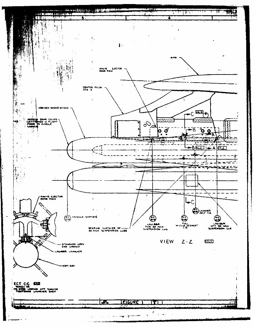
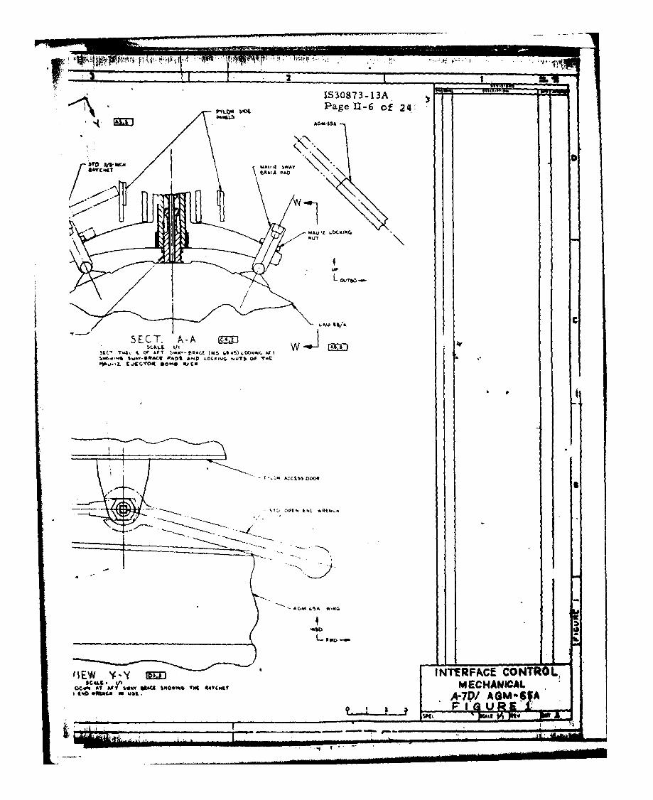
3.2.1.1.1 Mechanical interface. The mechanical interfaceof th2 aircraft segment and the missile segment shall be asdefined in Figure 1.
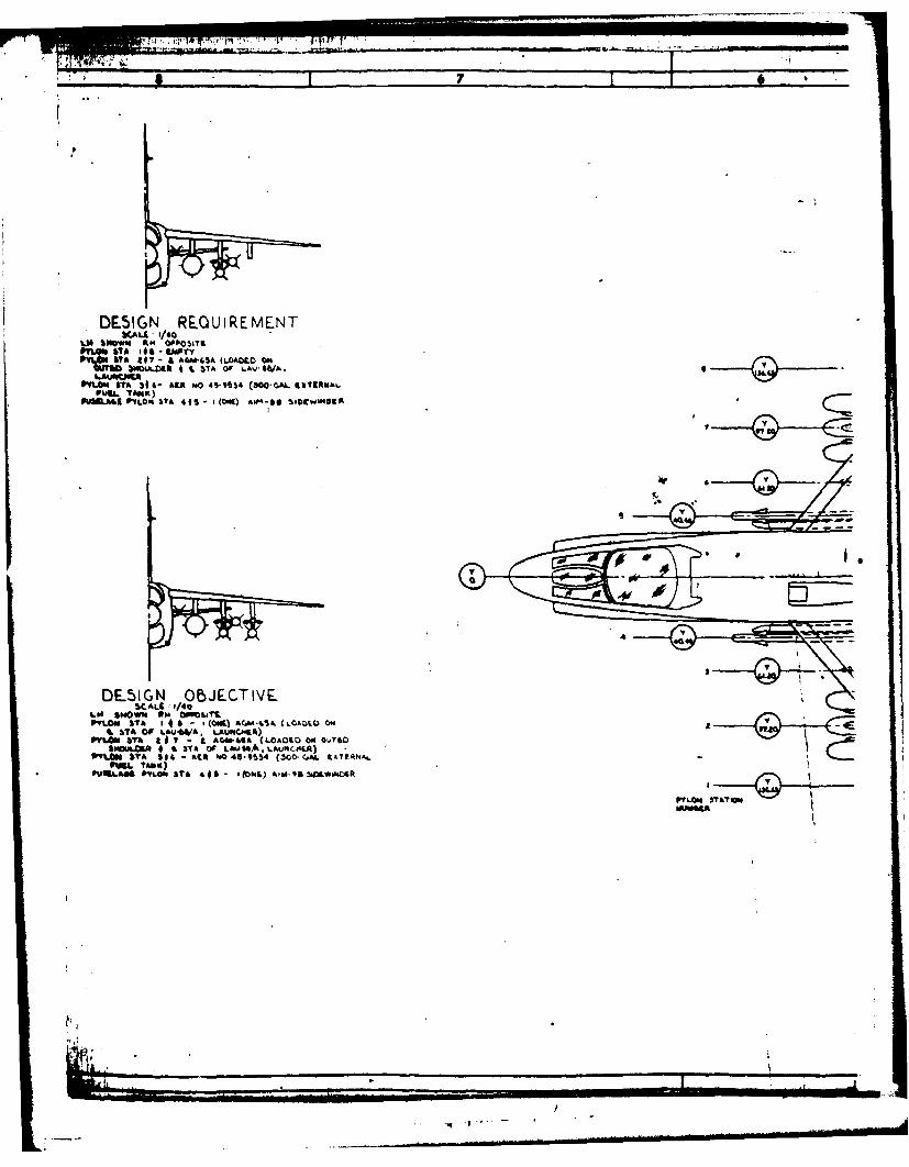
3.2.1.1.2 Carriage configuration interface. The carriageconfiguration interface shall be as shown in Figure 1.
3.2.1.2 Electrical interface. The electricl interfaceshall be at the aircraft adapter connector in 6ne -aircraftsegment mated with the launcher interface connector in themissile segment as shown in Figure 2.
3.2.1.2.1 Electrical power. The aircraft segment shallprovide at the interface, and the missile shall be capable ofaccepting, the following power forms.
3.2.1.2.1.1 AC Dower. The AC power provided by theaircraft segment shall e as specified in Table I and shall becapable of meeting the power demand of Figure 3. This powershall meet the AC power requirements of MIL-STD-704, Category B.
3.2.1.2.1.2 DC ower. The DC power provided by theaircraft segment shal as specified in Table I and shall becapable of meeting-thepower demand of Figure 4 plus the squib-firing pulses of Table II. This power shall meet therequirements of MIL-STD-704, Category B.
i °

.lop
TRage( £11. 5LA of2
AFT~~U. LLJLlt'CT .5L! DO
T~ IS/A Q40( FULL OSLECT PL-
-~ ~ ~~T t~~~( ~(~
lAATFV 1 - E 'lUAM~Cd W MT~ @
-~~S % -omct - - ---- ftc"Cr~'U
LAU"( -CR U'-'aULAL A4CAPT(R
LU6
.AUNCM1VER.PE
r PERACC CONTROL-
FIGURE I
WN L .. .
- ------------
I IAMJ-t LaLCTyf
I. cst4 PYL04
g! MI$WST
,~OR)
41~~~ A-0 0.01
rLL
LAU.S&~L i=L~(M W
KA3~G ~RACC3or--~ IU ~O,84C8 A
30 I.C4 ~~P~N04 L ~ U1~t4S0j&
0S A U. L&UW.WC
ECTWL CCC&
tC -*-

- .S& 30
3S71
~1ij
M&U.IL 00(C1OA
ACCIMS
LPAbICN %t"p ph. ves
6t3!w A
K&teem m
Page 11-6 of 214'
*ITOl SA- MAV' !,A
MAVI~ LO(.(IN4
UP
L*hJ 1/1A C
5L T.9 IL Or &FT I*A'- ftRAU (M5 0.,.5)LDDc.m, ASIl.0 4 tt.av-o*Act #,asI AND VC~* b .. uIof
P~~*,j-topt tjC. O *OMO UI1
UU $a
Soft !R AtE 211 fOLOC.. Al D? feA'rgl~d~NOWg~ IS Slot4

MUAI caRTRIDed
STOD ODE". L..D WqMC.
AVt .ywk)
1.D 046C. LbC..
ts* AND V1
-4
___ __ __ __I_ F-.o( tIU I T

ANSI'505,1
c1~&4650---'s
'IN& .. A,'L EjECTOR PISTON4M&
gV A~jw5 ~h..*'C R&T*
IlkVIEW' u-u K2VIEW .oag'ic. Do"i -*. "'A" uaw" T.9.INS T, -&.oN or -- C SAVCV Pew AND
REA.Clt
31CALEt* Do,%-N( C4~ Ar b AC4
*Kct@" ro.
-- A-
MA
pi
LUfO
4040tYO IMPULSX CDA'S 01"I 1ATORliG (I ocamitt)
IICT LMMQ arf ".4 SJK W s. or lt ABA £Y'%" 141D TIMV IEFW w-w 4' o(4C1L stvls$ew os
SCALEA1? -s 1/01 v6Ic c ~ liv-ft wvka:SL-1-0 i/iIM INICtN GODWIN15 * t..'i06ig,~es
ANBD T0iii4" ,Nor T S'iAWIJ cj ~o
AA.S1*utwiN OP YS p~ui.L £j~Al

IS30973-13A-Page II-7 of 24
NJOTES;L. Otd( M4A&. LAJO'496 SCAM
Toe ftAI9 a4 c4. -A-ft%AMII* %CA# 6 &..@ 9
9,2 AOOdl bfscoavrf,
S. 9VAt1c 6m.O'O 6,4 064
ow~ 10.46 bAPID p*Sp4t(?AP4) PlAV 68 CA44#40 1##.ICU 067 ALL AG14.ASA P*6okt
I ~PitIO 0% PYLON STATIONI I AWWOPI 7 '14,M ANO A&Mi6%4PYLON &1TAT,0'. 1 0 CARIeLM luF. wT
SOW PYLO #XArOM.~w
DESIGN RESQUIREMENTTA 148 AI4O 346 -EMP~TYTA L q? - A A"M-4A (3 tot ft0Ta~ 44S IL £ A7m-.* 'PI
1, 0-OuTbobso plu.o" belI 0. MCCHAYNJ JtCALmePIoMNoi GA09J'O (,*-a 0 A. 7O/AGM-GSA
Il a * I N COC S 41 I'c' o v o l2 . J .
W~~~~~ ~ ~ ~ Op.m yois(c-, s~c 4 6.

- - - - - - - - -
*D
M
AGO-&"S 5'@6*'lOS
IM, I FIGURE I 7 I
-f r
7f7
DESIGN REQUIREMENT)CALL - /40
L" w~i ft' OPPOSIT9PYLe. STA If$- I.MPrvf
P 107 t £ A &W#*4'A (LOAOLO ONLAUWUS
PlO.STA 39~ 6 R hLAO 45-9554 (300-GAL 91CRVIhLPURL. 'TftK)
PRiS.A&K P~fLC. S?6 41S I iCONQIIAM-90 5iVCWsN4SA
DEIN OBJECTIVESCALE 1/40
LW 40 HWN Os OM3aITPVLJOw I76 1 461 - I(OWN) AfM46 (L.ADL ON
t STA OF L6J41'A* ILuwcJ41t)PVLGN 316 a j7 - I C 604i-4I6 LOAO%.O ON OV1bO
SSHuL0I 4 -L S7A or LAUWALAUM0CPA
OWL TANK)VUILASS VYLCO 3TA 44 0 1(wI) A10-96SiO.L*NCAR
FILON 3AW

IS30873-1 3APlage 11-8 of 24
AG 51 1M~S ~S~f~)PLL h
P A ELrTL&.. F A;
DT T L = i
TIC AV-BA .10 DIO A.L P A4M..,
s 00 m~gr
NI- PA-R EKE:]6.'
t*"yP~m~ $CLVI ~TA8N F LASAAINTRFsACE CONTROL
A-DASAV *i
~~A~L LLJFIGURE 1_____Pit___________________

ACCAISS ooa OUThO&Ub *'VLON
/~ (IV9 A .)f,
- 0
'PCN POS.T-
r oc.rmor~t L'c SI -
MR .i TOT"; I.-0
crcos otem~VIEW t~M vote
,O!UCALI I pt
vr.............CTO ACC~

ANY £.LCTRICAL COMPARTMENT CETE DILA a.
&cci~ oomLA&WV&RD PULL. bAf
I -
I lilT,~ MASTER
-. 0- F{-{ _
uA-p '3 I-L0K taL
SIAINO UAACI-/8TAL 00 ~4NG 'N*'./.t) 1( A
LAU-S&VA *N/ T4C( /AEm P O,
rOMPAIL1
%0.S 0
VIEW P-P M3"Alo grvwf~vSrCLL , i/i
VIEW L.OW'"4 UP AT API CLRC MCAL COPAOTAtoo ismoilso~sc '(IOki 1MOomw mooap-e 4c [email protected] aCTOft&me 8%A IP4 OFC'b'NB or aCSS OOOR W,?.4 0I fiBi, oceI ow sololo S?&?oONJOP ^Ubo

IS30873-01 3Ac Page IT- 9 of 24
AIRCRAFT SEGMENT PIN MISSILE SEGMENT
SA TST FUNCTION
ADAPTER EXCITATION(4) S ADAPTER EXCITATIONI )
+ZSVDC POWER C 02S VDC POWER
JAHUAL SEQUENCE 0 MANUAL SEQUENCE
MASTER M SPARE E SPAREKYASTARBOARO IDENTIFIER F STARBOARD IDENTIFER
STATION SELECT S STATION SELECT
AIRCRAFT H LAUNCHER PRESENTFORWARD
, TEST FUNCTION
AZIMUTH COMMANO K AZIMUTH COMMAND
A ELEVATION COMMAND L ELEVATION COMMAND
OV ® c) M TEST FUNCTION
N F-4 f'hTIFIERq) (2) .2® -POE .D~VOC POWE P .OCOVER POWSR
AA (1 OZ ISOLATION R ISOLATION
OT 3 ISOLATION T ISOLATION
FRAME GROUND U FRAME GROUND * e
a ] SPARE V SPARE
- G)/ 2 W TEST FUNCTION
@ 000 Th 2 F-4 UNCAGEADAPTER EICITATION(-) Y ADAPTER EXCITATION-)
:.)TRACK ING MODE Z TRACKING MODE
ASM-65A IDENTITY j ACM-GSA IDENTITY
KTRACK TRACK
ASM-6SA SELECT A GM-GSA SELECT
SPARE 4 SPAREJ I 9. TEST FUNCTION
(iENOIX CONNECTOR) A TEST FUNCTIONLJTORE-25-46 PS) 3 AC POWER, NEUTRAL 2 3EAC POWER, NEUTRAL
Z525U HAC) SELECTED MISSILE READY SELECTED MISSLE REApF
FRONT FACE OF PI INSERT SPARE SPARESPARE I
A SPARE
NOTES; U2] SPARE SPARE
DC ANALOG RETURN DC ANALOG RETURNI. THE ABOVE CONNECTOR IS SINGLE SSALE pETTISON P SE44.E S1.1 JETTISON
USED ON THE ELECTRONICS 4 LAUNCH
UNIT, LAUNCHER.PART NO. 10Z3568 LAUNCH LAUNCH
NO CONNECTIONTO THIS TEST FUNCTIONPIN IN AIRCRAFT SEGMENT U t TES UNC ON
A-7 UNG-AG A J-? UNCAGE
] NO CONNECTION TO THIS 3d AC POWERfA It 3AC POWER,APIN IN MISSILE SEGMENT COMPOSITE VIE O COMPOSITE VIDEO
4. PIN LETTERS THAT ARE SS1AC PONIR, 00 SEAC POWER.,$
UNDERLINED ARE LOWER 34 AC POWER,# C f 3AC POWER,OC
CASE LETTERS M2SPARE i SPARE
2a VDC RETURN AA 26 VOC RCTURN
FIGURE Z. INTERFACE taORhox.- ELECTRICAL A-1AM-r1 ,

IS3087 3-01 3A
Page II- 10 of 24KTABLE I. POWER FROM AIRCRAFT SEGMENT
SIGNAL INPUT RETURN SIGNALNCMENCLATURE PIN PIN FORM
THREE PHASE ENVIRON- 3-phase, 4 wire, 400 HzMENTAL AC POWER and 115 VAC Line-to-NeutralNeutral (fourth wire neutral
Phase A v grounded to aircraftPhase b x frame and launcherPhase C Y frame).Neutral
+28 VDC ENVIRONMENT- +28 VDCAL DC POVXR and+28 VDC Return C AA Return grounded to
aircraft frame andlauncher of rame.
S.
o9
IS3 087 3-O01 3A
Page Il- 11 of 24
OR C
NN O
-0 e 0 --
V -C
+ T. n,-
- E E
Oa ..
L6. '4. ..
a. uln
'A taL2 5

ji
IS30873-013A
C. Page II- 12 of 24
-iz 8<
ttie 9. - 8
2 w
.c w w
'- l-i'
INI
0 .___________ Cai':~.w c
0V
C;
1, W.
: 0l W. NO t
~ ~ 0 4
~T C' ~t____~ ___412
_______ _________ - do
6-
4.:1!

IS3087 3-01 3APage II- 13 of 24C
TABLE III. SIGNAL AND NOISE CHARACTERISTICS
SI GNAL NOISEITEM TYPE SIGNAL CHARACTERISTICS CHARACTERISTICS
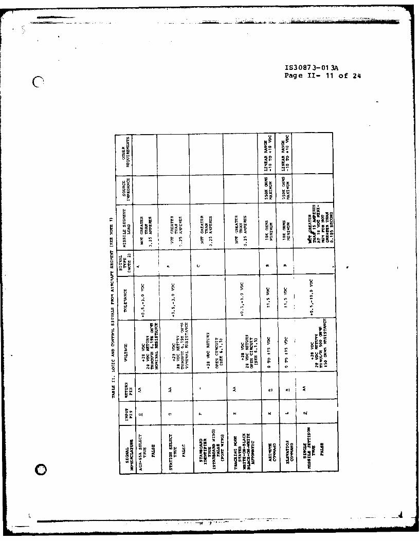
I A Two-state logic; logic True Ripple and transientshall be nominal 28 VDC air- voltages shall notcraft power as specified in exceed those speci-MIL-STD-704, Category B. fied in MIIL-STD-704,Logic False shall be 28 VDC Category B.return, through a 500±50 ohnresistor. The line voltagedrop shall be in accordancewith Z1IL-W-5088.
2 B DC analog signal. The noise shall benot greater than 0.1VRMS with transientsnot g%'eater than ±0.5volts peak.
3 C Two-state logic; logic Ripple and transientTrue shall be 28 VDC return, voltages shall notLogic False shall be open exceed those speci-circuit (see 6.1.5). fied in MIL-STD-704,
Category B.
o*
0 :-"
. .. -'t- 7... . -"

IS30873-01 3APage II- 14 of 24
0 0
IA2Z
m -0 Z 0 Z 0
tn
N OR'.3b
-3l
mn a c
In9
In4

IS 30873-01 3A
Page 11-15 of 2(l
115 VAC, 400 HERTZ. 3 PHASE
1100 NOTE:
1050 1. MAXIMUM CURRENT PER PHASE1000 SHALL NOT EXCEED 5 AMPERES.
900-
800- 75075
700-
500--o.j 3 MINUTES
400 MAX
200-
100-
I I I IAIRCRAFT AGM-65A READY UNCAGE LAUNCH LAUNCHPOWER ON SELECT INITIATE COMPLETE
Figure 3. Maximum 3 Phase AC Power Demand (Pin vp M, X to Pin 1)
0W-7

IS3087 3-01 3APage II- 16 of 24
3.2.1.3 Electronic interface. The electronic interfaceshall be at the aircratt adapter -connector in the aircraft -
segment mated with the launcher interface connector in themissile segment as shown in Figure 2.
3.2.1.3.1 Logic and control signals. The aircraft segmentshall provide at the interface, and the missile segment shall becapable of responding to, the signals listed in Table II havingcharacteristics specified therein. Signal and noisecharacteristics shall be as specified in Table III.
3.2.1.3.2 Missile senment response signals. The missilesegment shall provide at the interface, and the aircraft segmentshall be capable of accepting, the signals listed in Table IVhaving the characteristics specified therein, and the COMPOSITEVIDEO signal having the characteristics specified below and inFigure 5. Signals and noise characteristics shall be asspecified in Table III.
a. Load impedance - coaxial cable of 95±3 ohmscharacteristic impedance, terminated in 91±9.1 ohms.
b. Source impedance - 100 ohms maximum.
c. Signal form - a 525 line raster with 30 frames persecond and tw fields per frame with positive two-to-one interlaLe and 1:1 aspect ratio.
3.2.1.4 Hydraulic-pneumatic interface. Not applicable.
3.2.1.5 Environmental control interface. Not applicable.
3.2.1.6 Crew provisions, displays, and control interface.
3.2.1.6.1 Crew provisions. Not applicable.
3.2.1.6.2 A-7D aircraft video monitor display. Theaircraft segment shall prov id e a tel evision (TV? displaycompatible with the COMPOSITE VIDEO signal of Figure 5. Thedisplay shall provide a TV picture of equal height and width.The horizontal and vertical scans shall each start in the upperleft hand corner of the display as seen by the pilot.Resolution, contrast, and persistence capability of the displayshall be compatible with the COMPOSITE VIDEO signal of Figure 5.(See 6.1.6 and 6.2)
0
/
" - ..... -- ....... .............. ......................... .. Ullili i iiI . . ..

IS30873-01 3APage 11- 17 of 24
400 -
300-
200 -I
AIRCRAFT AGM-65A READY UNCAGE LAUNCH LAUNCHPOWER ON SELECT INITIATE COMPLETE
Figure 4. Maximumn +28 Volt DC Power Demand (Pin C to Pin AA)

1S3 087 3-01 3APage 11- 18 of 24
CLl
0
4o 0 0 Tz:) +2 2 .. I(
2w
LLI->
04
0 CL
+1 ae E1
> 4. 0) 0-
-j w 0
wc z 0z Lm U o. 81, 0N AL
EE-z A
0
0 <. D 00
wZ z .. Zug0. wE0 0 .2Z e.x I0 I tcc 5 +1 0 E4 -
w --> 4
> 0- zIU> x
46 1
LI
IS30873-01 3APage II- 19 of 241
3.2.1.6.3 A-7D aircraft target acquisition controls. Amanually operable target acquisition control shall be provided inthe aircraft cockpit to independently generate the AZIMUTHCOMMAND and ELEVATION COMMAND (cammand signals) of Table II.This control shall generate the specified signals when excited bythe ADAPTER EXCITATION (+) and ADAPTER EXCITATION (-) signals(excitation signals) of Table IV, provided by the missilesegment. The magnitude of the command signals shall beproportional to the deflection of the control from its nullposition with a linearity error of not more than ten per cent. Apositive AZIMUTII COM4AND shall be provided to the missile segmentwhen the pilot desires to slew the seeker head toward a starboard(negative Y) direction (Figure 6). A positive ELEVATION CCMNDshall be provided to the missile segment when the pilot desiresto slew the seeker head in an upward (positive Z) direction. Themaximum values of either command signal shall be not less thanninety-eight per cent of the applied excitation signals. Thevoltage of either command signal, with the control in the nullposition, shall be not more than +0.6 volts and no% less than -0.6 volts. The resistance of the control device, including theresistance of switching and wiring between the interfaceconnector and the control presented to the excitation signals,shall be not less than the load impedance specified in Table IV.(See 6.2)
3.2.1.7 Weapon control interface. Not applicable.
3.2.1.8 Transient susceptibility. No temporary orpermanent degradation of performance or malfunction shall beproduced in the ANM-65A missile segment equipment when 600 voltpulses are induced on each ungrounded dc power line and 100 voltpulses are induced in each ungrounded 400 Hertz power line.Pulses shall be of positive and negative polarity, shall have apulse width of 10 microseconds, and shall have a pulse repetitionrate of 60 pps for dc power lines and 10 pps for ac power lines.
3.2.1.9 Armament greparation. The AGM-65A missile segmentwill respond to power and signals from the aircraft as specifiedherein.
3.2.1.9.1 Environmental conditioning. All AGM-65Amissiles shall receive environmental conditioning power when theaircraft electrical system is activated.
3.2.1.9.2 System activation. The pilot readies AGM-65Aweapons. The missile seeker gyros and vidicon cathode heatersare prepared. After a preparation time delay, an indication ofweapon readiness may be observed.
3.2.1.9.3 Enable firing circuits. The pilot shall enablewill-t-o-f ire cn ro u-.

IS30873-01 3APage 11- 20 of 24
Z (POSITIVE)
X (POSITIVE)
FIGURE 6. AIRPLANE REFERENCE AXES
IS30873-013APage II- 21 of 24
3.2.1.9.3 Enable firing circuits. The pilot shall enablewill-to-fire circuits.
3.2.1.9.4 Visual search. A visual search is made for atarget. Upon target detection, the aircraft is placed on aflight path to align the HUD reticle with the target.
3.2.1.9.5 Uncae The missile seeker in firing priorityis electrically al idto the armament reference line when theuncage switch is activated. Missile video with crosshairs isavailable at the time the seeker is electrically aligned.
3.2.1.9.6 Lock-on. The pilot finds the target on the TVdisplay and slews the seeker head to acquire the target with thetracking gates. A lock-on is commanded when the target is withinthe tracking gates.
3.2.1.9.7 Launch. The pilot initiates lauach after lock-on to the desired target.
3.2.1.9.8 Abort. If the missile in firing prioritymalfunctions, the pilot may select a succeeding missild dh thesame launcher. If the missile in firing priority did not trackthe desired target or the pilot did not gate the desired target,the uncage and lock-on, or lock-on only steps may be repeated.
3.2.1.9.9 Single missile jettison. Any missile in thefiring priority may be jettisoned individually.
3.2.1.9.10 Select/salvo jettison. A selected launcher andits associated weapons can be individually jettisoned from theMAU-12 hooks, or all stores on the aircraft wing stations may besalvo jettisoned.
3.2.2 Government-furnished property list. Not applicable.
3.2.3 Standards of manufacture, manufacturing processesand production. Not applicable.
0
2 II| I I III I IwI iL- -

IS30873-01 3APage II- 22 of 24
4. LVALITY ASSURANCE
4.1 Product performance and configuration requirements/quality verification cross-reference index.
Characterisitcs Section 3 Section 4
Physical interface 3.2.1 4.2
Electrical interface 3.2.1.2 4.2
Electronic interface 3.2.1.3 4.2
Crew provisions, displays, 3.2.1.6 4.2and control interface
4.2 Test verification. The A-7D aircraft segment and theAGM-65A missile segment sDall be verified separately. Theinterface shall be verified in accordance with athe qualityassurance provisions of CEI specification CP30873-q31 and theapplicable provisions of ICP VO-A7-392.
0
©H

9]
IS3087 3-01 3APage I- 23 of 24
5. PREPARATION FOR DELIVERY - Not applicable.
6. NOTES
6.1 Definitions.
6.1.1 AGM-65A missile segment. For the purpose of thisinterface specification, the AGM-65A missile segment shall belimited to the following elements:
a. AGM-65A Missile (CEI 506021A)
b. Launcher, Guided Missile, Aircraft, LAU-88/A (CEI50603 1A)
C. Guided Missile, Training A/A37A-T1 (CEI 506041A)
6.1.2 Aircraft segment. For the purpose of fhis interfacespecification, the aircraft segment shall consist ol that portionof the A-7D aircraft which makes a direct contribution to thecarriage, control, and operation of the AGM-65A system, includingthe MAU-12C/A Bcmb Rack (USAF drawing 69J13060), and the rfasterharness of Figure 1, sheet 4, which connects between the adapterconnector, mating with the LAU-88/A and the pylon connector.
6.1.3 Tolerance range. Wherever there is a range ofvalues specifie"lerein, e.g., 0108 to 121 VRMS," the range isdefined to include the limiting values.
6.1.4 Continuity. Continuity is defined as a resistancenot greater than2ohms.
6.1.5 Open circuit. open circuit is defined as aresistance not less than one megohm.
6.1.6 Aircraft television display. The aircrafttelevision display shall have a horizontal resolution capabilityof not less that 600 television lines for 10 percent square waveresponse, a contrast of at least 8 shades of gray at 750 foot-lamberts, and a persistence of not more than 15 percent on thefourth frame.
0

IS3 08 73-O01 3APage 11- 214 of 214
6.2 Verification of 14AVERICK carrier aircraft displays andcontrols. During the Government conduct of MAVERICK (WS-319A)Category II testing, the followirq verifications wereestabl ished:
a. The cockpit display of the AN/APQ-126 Forward-LookingRadar System as specified in document VAD 2041-16-13met the roquirements of 3.2.1.6.2 herein.
b. The AN/ARW-77 BULLPUP Controller met the targetacquisition control requirements of 3.2.1.6.3 herein.
10. APPENDIX -Not applicable.