AD-766 172 CUTTING ICE WITH HIGH PRESSURE … 172 CUTTING ICE WITH HIGH PRESSURE WATER JETS Malcolm...
31
AD-766 172 CUTTING ICE WITH HIGH PRESSURE WATER JETS Malcolm Mellor, et al Cold Regions Research and Engineering Laboratory Hanover, New Hampshire 16 July 1973 DISTRIBUTED BY: LRjin a. S. DEPARTMENT OF COMMERCE 5285 Port Royal Road, Springfield Va. 22151
Transcript of AD-766 172 CUTTING ICE WITH HIGH PRESSURE … 172 CUTTING ICE WITH HIGH PRESSURE WATER JETS Malcolm...

AD-766 172
CUTTING ICE WITH HIGH PRESSURE WATER JETS
Malcolm Mellor, et al
Cold Regions Research and Engineering Laboratory Hanover, New Hampshire
16 July 1973
DISTRIBUTED BY:
LRjin a. S. DEPARTMENT OF COMMERCE 5285 Port Royal Road, Springfield Va. 22151
Technical ktport Documentation Peg«
T. Report No.
CG-D-15-73
2. Government Accettion No« 3. Recipient! Cotolog No.
4. Titl» otid Subtitle "
Cutting Ice with high pressure water jets
7. Author'»;
M. Mellor» JL Gragnon,
5. Report Dot«
July 1973 6. Performing Organ*«otion Cod«
8. Performing Orgonitotien Report No.
9. P♦»'terming Organ* totion Norn* end Addrets
USA CRREL Hanover, H.H. 03755
10. Work Unit No. (TRAtS)
Project NO 731313 11. Contract or Gront No.
MIPR 270099-3-32744
12. Soontoring Agency Nome «nd Add'«»
U.S. Coast Guard 400 Seventh Street, S.W. Washington, D.C 20591
13. Type o* Report ond Penod Covered
Final Report Id. Sponsoring Agency Code
IS. Supplementary No»«»
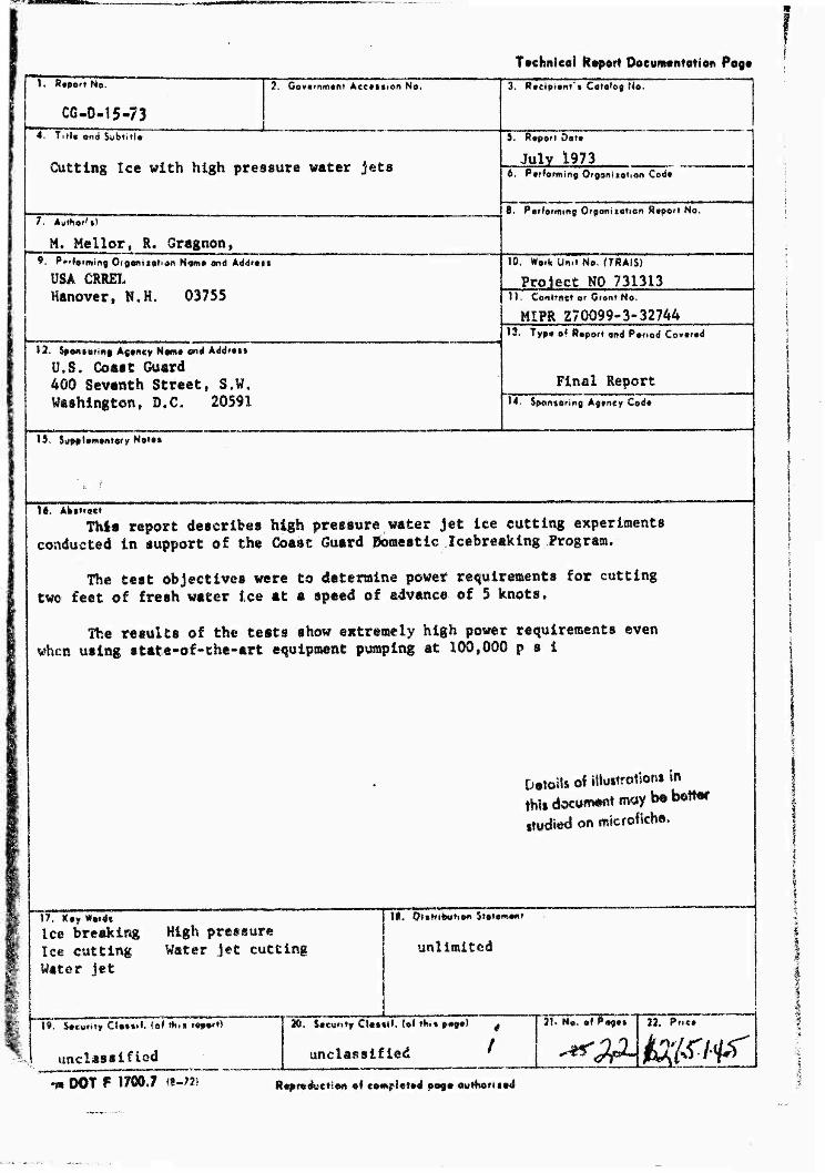
It. Abstract TWra report describes high pressure water jet ice cutting experiments
conducted in support of the Coast Guard Uoraestic Icebreaking Program.
The test objectives were to determine power requirements for cutting two feet of fresh water ice at a speed of advance of 5 knots.
The results of the teats show extremely high power requirements even when using state-of-the-art equipment pumping at 100,000 p s i
Details of iWuitrotiont in thUdocumtwtmaybebenef
ttudied on microfiche,
17, Key Wordt Ice breaking High pressure Ice cutting Water jet cutting Water jet
II. DutrttMttOff Stetemmt
unlimited
19. Socwrity CIo*it*. (o* th»i report)
unclassified
•» DOT F 1700 J «-;*)
D, So«v»*y Cl*i*i», (of ih,% pogo) #
unclassified '
lU No.~o« Poge» 22. Price
^^Msi^r Reproduction «f co«p!e»#d 009* ««»Horu»*l

f
•rt No. CG-D-15-73
CUTTIN6 ICE WITH HIGH PRESSURE
WATER JETS
^8 9*V<. ?V:<- i-Hv
NATIONAL TECHNICAL INFORMATION SERVICE
FINAL TECHNICAL REPORT
HAY 1973
Document Is available to the public through the National Technical Information Service,
Springfield, Virginia 22151
Wetttiitftofft, O.C $0590
i iff :W7
■&

*:*Mm&iVm^Wtt*V*fir>i
DAT«; 18 JÜL1973
This report has hem submitted in fulfillment of MIPR 2^7.00^)^)^3[IT-U and Ls promulgated subject to the following qualifications:
The contents of tULs r-:->orf; reflect the •/L*^K og U.S.A.CRRfiL M^VPJi^ Ji^iJ^^vili? 03735 wfii-h ii Cdspoa.UM.?. f>r the facts and ;;he ^curacy of ':*« data pr?*imti%d ho-; La. The contents do not necessarily reslect the offL^Ul viaws or 4*oli":y of the Coast Guard. This report doe.? not coast It'll-*», a »tiudarl, specific**: l.on, or ce^n} itiou.
C.T?=8LASS Captain, U.S. Coast Guard Chief, Marine Safety Technology Di/iUon Office of O^irch and llavolopatent U.S. Coast Guard Headquarters Washiigtoa, D.C. 20590
[ Raprodwyd Jrom b#st »va»l«b!« copy
/7
f;- mmummmemmm^MmmiJutnii mmt0mmmMmmtmamtif'%
Table Of Contents
*#* Objective Iff
Purpose » ........ i
Summary Of Results > *
Conclusions. • • - «I
Discussion ,. > *
Ml

Objective; To conduct large scale field experiments to determine the
powar requirements of cutting ice with high pr*3sure w.ifcer
Jets.
Purpose: To compare water jet ice cutting with other methods of ice
disaggrigatiwt.
Summary Of Results:
A water jat ice cutting system capable of slicing though ?,
ft* of ice at a traverse speed of 5 knots, operating at nw
100,000 psi would require approximately 1500 hydraulic
horsepower corresponding to about 3,000 prims mo*er horse-
power with present state of the are equipment*
Conclusions:
Continuous ice cutting with high pressure water j-»ts is no':
a feasable method of ice disaggrigation due to:
1. Excessively high power requirements
2. Unreliable state of the art high pressure water jet pump-
ing equipment»
b'
ikiämi^ä^^im^^im jmwaä»*»** ottt» *m^1bmximur&MKf^ tteni****: ■ - /»
)WMt-ft««U>i»ltf»*WW''>W»i.'*i«-«
JET-CUTTING AS AN ICE-BREAKIHG AID
Preliminary Report on Field Tests for ü. S« Coast Guard *
Malcolm Mellor and Francis Gaynon
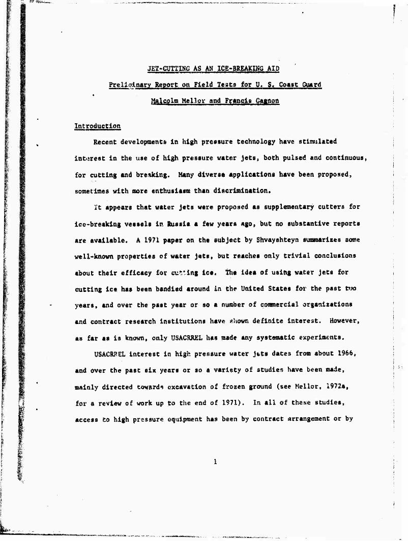
Introduction
Recent developments in high pressure technology have stimulated
interest in the use of high pressure water jets, both pulsed and continuous,
for cutting and breaking. Many divers« applications have been proposed,
sometimes with more enthusiasm than discrimination«
It appears that water jets were proposed as supplementary cutters for
ice-breaking vessels in Russia a few years ago, but no substantive reports
are available. A 1971 paper on the subject by Shvayshteyn summarises some
well-known properties of water jets, but reaches only trivial conclusions
about their efficacy for cubing ice* Th« idea of using water jets for
cutting ice has been bandied around in the United States for the past tuo
years, and over the past year or so a number of commercial organisations
and contract research institutions have «hown definite interest. However,
as far as is known, only USACRÄKL has made any systematic experiments.
USACRREL interest ia high pressure water jets dates from about 1966»
and over the past six years or so a variety of studies have been made,
mainly directed toward* excavation of frozen ground (see Mellor, 1972a,
for a review of work up to the end of 1971). In all of these studies,
access to high pressure equipment has been by contract arrangement or by
WWPW—I
«collaboration with other institutions« This approach has proved beneficial
in that It has been economical, it has provided experience with a variety
of equipment, and it has avoided enslavement to one particular type of
capital equipment. During the course of tests on frozen soils» a few experi-
ments were »ad« on ice blocks (Summers, 1971; Mellor and Harris, 1972) and
the» results were used to evaluate the material constants needed for analytical
design methods (Mellor, 1972a, 1972b).
In the autumn of 1972 USA&cJLEL received informal inquiries from the
U. S. Coast Guard about the possibilities of using water jets as ice-breaking
aids on Inland waters. At that time» design estimates based on results of
small-scale laboratory experiments indicated that a jet capable of slicing
through 2 ft of floating ice at a traverse speed of 5 knots would make
unreasonably high power demand* (Mellor and Harris, 1972), However» recognising
that no field tests had been made, and that new equipment capable of pressures
2 up to 100,000 lbf/in was being offered, it was conceded that It would be
prudent for the Coast Guard to include Jet-cutting tests in its FY73 research
program* Consequently, USACR&EX submitted a proposal for field evaluation of
«that appeared to be the most advanced continuous-jet unit in existence at
that time.
Test Program
Technical plans drawn up in November 1972 called for one week of
systematic field tests on a small lake near the USACRREl laboratories in

Hanover» N. H.» the tests to begin on 19 February 1973, A 100,000 lbf/in
Jet unit developing 200 hydraulic horsepower was to be leased from the Illinois
Institute of technology Research Institute (IITRI), and the unit was to be
operated by a senior engineer and a technician from IITRI. The test matrix
was designed to investigate the variation of jet penetration with nozzle
pressure, nossle diameter, and traverse speed.
Due to administrative delays the IITRI contract was not awarded until
after the planned starting date for the tests, and by this time the IITRI
unit was being reconstructed in the third version of the prototype» so that
further delay encued. The jet unit was not ready for shipment until 19 March»
and by this time abnormally early spring conditions had caused serious deteri-
oration of the lake ice In New England• A rapid survey or ice conditions
indicated that early breakup was general in the northern states, but a
decision was made to attempt field tests at the Keweenaw Field Station,
Boughton, Michigan, where the required 2 ft of Ice still existed in apparently
sound condition.
The IltRI high pressure unit arrived at Houghton late on Wednesday,
21 March, and was off«loaded on Thursday, 22 March. There were logistic
difficulties in preparing the unit fcr operation and in moving It to the
test site (among other things, the unit sank in the mud and the bulldozer
broke down), but by mld~aorning of Friday, 23 March, the unit was on the
ice and ready for testing (Fig. 1).

*m*&mimmm*i*m**i.-~
Since It seemed possible that there might be trouble with both the ice
and the equipment, the original test plan was discarded and the* program was
started with the grand finale, i.e. full hydraulic horsepower, maximum
pressure, maxitmim nossle sise, and operational traverse speeds.
At the start« the power trailer and intensifier skid were towed across
the ice by means of a winch and cable, but this improvised arrangement
only gave speeds up to about 1 knot, and the motion was unsteady. A direct
tow with a light over snow vehicle was then attempted, but this 2^-ton machine
was unable to move the 7fe~toa IITRI unit. It was then decided that a tow by
the HD«5 Traxcavator (about 6-ton) would have to be risked. Two good test
runs were then made at almost 3 knots before the tractor broke through the
ice and sank (Fig. 2), at which time tests on floating ice were terminated
by decree of the equipment superintendent. Appendix A gives some notes oe this
bearing strength problem.
Ail equipment was retrieved and returned to the Keweenaw Field Station
on Friday afternoon» 23 March» and preparations for tests on ice blocks
were made. On the morning of Saturday, 24 March, the intensifier unit was
set up on blocks and a simple traversing track for ice blocks was laid
beneath the fixed noasle (Fig. 4). Ice blocks were cut from a nearby pond
with a chain saw, and were carried to the test vig in a Weasel. Soon after
start-up, the lugh-pressure seals failed on one cylinder of the intensifier,
and repairs had to be made. Two traversing tests were then run at 100,000
2 lbf/in end the seal* again failed, this time on both cylinders, so that

testing was terminated for the day. On Sunday morning the replaced seals
failed again immediately after the first run-up to 100,000 ibf/in , and after
further repairs the intensifier was still leaking« However, by limiting
pressure to 60,000 lbf/in and limiting nossie diameter to 0,016 in» it was
possible to operate, and some traversing tests, static penetration tests,
and jet length measurements were made.
By the end of Sunday, 25 March, the intensifier was leaking profusely
and spares and morale were running low. There seemed little likelihood
of obtaining much more u$eabie data, and therefore the test program vas
terminated.
Test Results
Before giving any test data it must be pointed out that the IXTRI unit
dors not give a continuous jet when operating at its maximum pressure and
f\ou rating, and the writers are not yet convinced that it actually delivers
100,000 Ibf/in2 when fitted with a 0.02 in. diameter noaaie. The unit spurts
at about 0.$ beats per second under high-pressure operation because there is
nc »urge chamber on the delivery sid** of the intensifier. Delivery pressure
is uncertain because there is no pressure gauge on the high pressure end of
the »system - pressure *s read from the low«pressure circuit, and is then multl*
plied by the area ratic of the intensifier« but the system has not been
calibrated. When the maximma-performancf jet craverses, penetration varies
cyclically from K-I to a maximum value as the nozzle pressure fluctuates.

™ *Q.*™w**>i!ViamM>eKc*M*, _„„
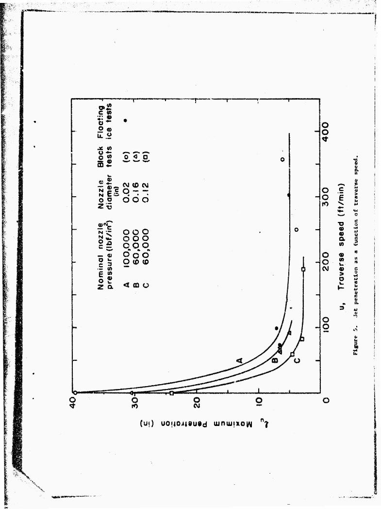
In all of the traversing tests, penetration verted cyclically from
zero to a maximum value, and it was assumed that maximum penetration
corresponded tth maximum delivery pressure. In Tables I and XI maximum
penetration is tabulated alongside the nominal delivery pressure, i.e. the
pressure of the low-pressure hydraulic circuit multiplied by the effective
intensification ratio of 20 (which makes some allowance for friction in the
intensii'ier). Traverse speed in the lake tests was measured by timing a
50-ft run with a stopwatch, and in the block tests it was measured by
timing the travel of a block (approximately 52 in« long) through the jet,
Noxtles were described as "Leach and Walker 13 noxsles," i.e. they were of
the design attributed by Leach and Walker to Nikonov and Shaviovskii, with
li° entry cone and a parallel exit section having a length/diameter ratio
of 2.5 to 3.0. traversing data are given in Tables X and IX and in figure 5.
Table I
T aversing tests ^n floatlna ice
Kominat Test Nojrxle die. Ko tale "pressure Traverse Speed >Max. Penetration Remarks
3
(in.)
0.02 100,000
50,000
gyy w ?ft/min^
69.1
99.3
302
280
linT!
6.5
7.0
5.0
2.0
Jerky travel
One cylinder of lntenslfler faulty.
Standoff distance approximately 1 in.

Table II
Traversing tests on Ice blocks
Nominal Test Nozzle dia. Nozzle Pressure Traverse Speed Max. Penetration Remarks
(in.) (lbf/in*)
1 0.02 100,000
2 ti it
3 0.012 60,000
4 ii II
5 ii II
6 0.016 ti
7 u ii
8 II !•
(ft/rain) (in.)
250 3.75
357 6,0 Jerky travel
189 2,75
83.3 3.0 Jerky travel
58.9 4.5
92.0 5.0
69.6 6.5 Jerky travel
66,0 6.5
Standoff distance approximately 0.75 in. for 0.012 in, nozzle and
1.0 in. for 0.016 in. nozzle»
Static penetration tests were run in order to set an upper bound for
penetration as traverse velocity tends to zero. For a penetration test, an
ice block was set up with its long dimension parallel to the nozzle axis
(Fig. 6), the nozzle was brought up to operating pressure with a steel
deflector protecting the ice, and then the jet was allowed to attack the ice
for 20 seconds. In some of these tests the jet broke out through the side
of th« block, since the ice on one side of each block was very weak due to
grain-boundary melting. In all cases the cavity cut by the jet tended to
" --< ■■-SUfrtimUfr

increase In diameter with increasing depth for about 90% of the total depth,
the few results obtained are given in Table III; It appears that static
penetration for small standoff it about 2000 nozzle diameters.
SssasJäanttttA?.« .ft1»,
Test Nozzle Dia. (in.)
fHuL (IbtVin*)
Penetration (in.)
Penetration
Standoff (In.)
Penetration+Staadoff Nozzle diameter
i 0,012 40,000 22,9 23.9 1992
2 M 60,000 28.1 29.1 2425
3 0.016 60,000 29 30 1875
4 M 80,000 34.5 35.5 2219
With a nozzle diameter of 0.016 in. and the feedwater pressure of 600 lbf/in2, the jet was allowed several minutes to erode a groove along the surface of a 0°C block; it eroded to a total distance of 51.5 in.
Some attempt was made to determine free-air jet length by simple means.
As near as could be ascertained by direct observation, the coherent Jet core
was about 1000 nozzle diameters long. However, the dispersed fringe of the
jet extended more than 3000 nossle diameters. When a wooden board was moved
backwards and forwards at the ex. amity of the jet there was a fairly distinct
transition from low impact force to a force of the order of 1 kgf, and the
distance from the nozzle at which this transition occurred was measured,
results being liste*! in Table IV. The apparent increase in dynamic length
8

with increase in nozzle pressure can probably be attributed to the method
of measurement; it would be more consistent to take as a lower limit of
force some percentage of the nozzle exit force. For most practical purposes,
however, it can be assumed that dynamic length is about 3000 nozzle diameters•
Table IV
Nozzle dia.
(in.)
Total dynamic length < >f jet in air
Test Nozzle Pressure
(lbf/in2)
Dynamic length
(in.)
Dynamic length Nozzle diamatei
1 0.012 20,000 35 2917
2 it 40,000 38 . 3167
3 M 60,000 39 3250
4 !! 80,000 40 3333
5 If 100,000 49 408^
6 II it 52 4333
7 0.016 20,000 44 2750
8 it 40,000 44,5 2781
9 ii 60,000 46 2875
10 M 80,000 54 3375
U If 100,000 55 3438
12 0.020 80,000 48 2400

mmammmimtMnmiimmmMm*,
Evaluation of Results
Prior to these tests some performance estimates were made on the
basis of earlier experimental work, and it is now instructive to compare
) *u
equation (Mellor, 1972b):
the estimates with measured values« Penetration r„ was estimated from the
pu - ?.[. - exp (-K2pÄ d/u) .] in which pQ is nozzle pressure (lbf/in ), d is nozzle diameter (in.),
u is traverse speed (ft/rain), and xQ and K~ are parameters determined
experimentally. The values taken for the parameters were:
• lOOOd - s
K2 - 9.2 x 10"7 (lbf/in2)"2(in.) ^ft/min)
where s is standoff distance in inches« Table V gives the comparison
of predicted values with actual values.
Table V
i Comparison of actual and predicted penetration for traversing jet
Nominal Traverse Actual Predicted ' Nozzle dia. nozzle pressure i speed
(ft/min) penetration
(in.) penetration
(in.) (lbf/in*) (in.)
0,02 100,000 69.1 6.5 17,7 »1 M 99.3 7.0 16.0
1 » ! It 303. 5.0 8.7
! " 50,000 280 2.0 2.9 i •> i 100,000 250 3.75 10.0 ; •* tt 357 6.0 7.75
0.012 60,000 189 2.75 >.l tt n 83,3 3.0 4.3 it ii 58.9 4.5 5.5
0.016 w 92,0 5.0 6.6 tf it 69.6 6.5 8.0 «i »« 66.0 6.5 8.3
10

WPPWPW
With one exception, the actual measured values of maximum penetration
are all lower than the predicted values, and the moat glaring discrepancy
occurs at the highest level of nominal hydraulic horsepower (Fig. 7), The
reason for plotting the comparative data against traverse velocity in Figure 7
is that there ought to be reasonable agreement between predicted and actual
values at the extremes of velocity (u-M) and u»***), with poorest agreement
in the mid-range of velocities. However, there are not enough results to test
this Hypothesis.
One thing that comes out of the static penetration tests at Houghton
is that the previously assumed value of Y is too low for physical reality,
although it may well be reasonable as a curve-fitting parameter for the data
available up to this time. In order to examine this question, -ln(l-ru/{)
has been plotted against (pM/u) for three different assumed values oft , o o
and the Houghton data, excluding the results for the nominal 220 hydraulic
horsepower, have been &dded (Fig. 8). It should be noted that logarithmic
scales are used only for convenience and clarity, and a linear relationship
between -In (1 - **/*0) *n<* (P0 <*/u) must have a slope of 1:1 on this type
of plot. Figure 8 clearly shows that this type of parameter determination
is quite insensitive to the assumed value of < unless the data involve
of L values of Y *Mt approach the value . Although these results have
not yet been checked by regression analysis, it appears that the best fit
is obtained with a value of v0 that lies between (lOOOd - s) and (L500d - s).
In any event» the situation with respect to the Houghton data remains unchanged,
U

mummammta
In that all results except one are low in comparison with previous results
according to this type of plot.
Actually, there are some indications that the analytical function
(p d/u) may give too much emphases to nozzle pressure* with the result that
predictions extrapolated to pressure ranges higher than the data range
are systematically overestimated. What this means in the present case is
that our predictions for very high pressure equipment (100,000 lbf/in2)
have perhaps been too optimistic«
While our design analyses may be in need of some refinement, they are
still perfectly adequate for making planning estimates, and it is worth
looking again at the probable requirements for a Jet that will cut 2 ft of
ice a£ a traverse speed of 5 knots. The simplest and least controversial
way to do this is to select various nozzle sizes and then calculate the minimum
pressure that will just give a 2-ft penetration at 5 knots; Table VI gives
some results for calculations of this type.
Table VI
Minimum requirements for single jet slicing 2 ft of ice at 5 knots
(assuming %Q » I500d - s? Kj « 5.0 x 10"7, s - 1 in.)
Nozzle dia, ~lin7)
0.05
0.10
0.15
0.20
Nozzle press (lbf/in2)
89,100
42,200
27,700
20,500
sure Hydraulic power of jet <h.p.)
llbO
1510
1800
2050
12

- i-wtrmax.
Conclusions
In spite of all the setbacks, this project succeeded in making art adequate
evaluation of the IITRI high pressure jet unit as it presently exists. The
following conclusions can be drawn:
1. There is absolutely no indication that the high pressure jet unit can
exceed the performance estimates made prior to these tests. There is a strong
possibility that mechanical inadequacies in the jet system reduced its
performance somewhat at high power levels, but elimination of these problems
would nor be likely to do more than improve the agreement between predicted
and actual performance. In fact, it may well be that the performance pre-
dictions for very high pressures are too optimistic.
2. A water jet system capable of slicing through 2 ft of ice at a
traverse speed of 5 knots would make exorbitant power demands« At the
practical pressure limit of available large pumps, a single jet nozzle
would develop about 2000 h.p«,, while at the absolute pressure limit of
current pump technology a single nozzle would develop about 1000 h.p.
These are values of hydraulic horsepower; the input engine horsepower could
be as much as twice these values. For a 3-nozzle cutter system the iartalled
engine power would thus be of the order of 10,000 h.p., which seems preposterous
for a vrssei working the Great Lakes or the St, Lawrence Seaway.
3. In its present form, the IIIRI jet unit does not appear suitable
lor sustained operation at full output pressure. There is very little
likelihood of It operating hour-after-hour and day-after-day, as would be
required for shipboard tests.
13
<«»«*»»*«•»«««»,» _„
Acknowledgements
The writers are grateful to the staff of the Keweenaw Field Station,
Michigan»Technological University, for their help in carrying through the
abruptly relocated field tests, and to Mr. L. E. Finlayson, Illinois
Institute of Technology Research Institute, for preparing and operating the
high pressure unit. They would also like to express their appreciation to
Mr. Albert F. tftiorl, USACRREL, for clearing administrative blockages, and
to Mr. Norman Ehrlich, USCG, for his patience and forebearance*
References
Mellor, M. (1972a) Jet cutting in frozen ground, Proceedings of First International Symposium on Jet Cutting Technology, Coventry, England (British Hydromechanics Research Association)«
Mellor, M, (1972b) Some general relationships for idealized jet cutting» Proceedings of First International Symposium on Jet Cutting Technology, Coventry, England (British Hydromechanics Research Association).
Mellor, M. and Harris, H. D. (1972) Jet cutting tests on ice. Technical Note, U. S. Army Cold Regions Research and Engineering Laboratory, Hanover, NH.
Shvayshteyn, Z. I. (1971) Cutting ice with a continuous high-pressure water Jett, Trudy Arktlcheskogo "i Antarkticheskogo Nauchno-Issledovatel'skogo Institute, 300, Leningrad, p. 168-176.
14

-V ■^-^HfHW»VlhmpiB^
Figure 1, Power trailer and intensifier skid on the ice,
Figure 2. KD-5 Traxcavator in trouble.

Figure 3. Power trailer in difficulty.
bttt tvafbbli || JUP Figure 4, Improvised arrangement for traversing tests on ice blocks,
p
c »
52
o)£ N 2^ O O H-5
«*£
o "« b
04 <0 CM
ooo
g£ ooo c5 ooo
C (ft
off
ooo O(0 <0
< CO o
o H
i
o o
o c > « o E
fO ±J
**■> «M :«w o
X? c 0
0) 0> 0 a c tn 5
o a «
o to
CM 4» ß > 0
O AJ I» a h- V
8 *» a
3
o •t
g
i
o
(u?) U0f|0j|8u$d uintu**ofl n? i
*«*i»n.w»™nni(F/

Figure 6. Itoprovised arrangement for static penetration teats on ice blocks.

p g
c ©
•»4
2
E
3) Q) a
<u a?
> O lb.
si $ e a o «
Of M &4t
** o 2
UOUOJ4 "9d £»J2JP*£d
x

^,.
;wp } > )■» f "'iTpryrj T—f""""''■'jrf,,rp"T''r*lwy'iW''"''M'''Trr t'"<Tr"rw^
0* SI ° si rM M O *- O
UJ •» *? KOI
«UoXi-JL.x.^4,—g.,. lUoJL LJ>^^ ~J^»-~~LUU-: u.L^^X^^^^J^^Jufc-i» o 9 5fJ 'Ö 'S
f

'4
57'I V/' \ I'l'l ' I f I ['Ml H ' 1 |MM ' I '
c
Ui o
x o O O
it it «^ o
*2
(0 O
-J O N_
o
M
«s 9 *•»
u (0
• e
E
c
43
c o
a **—
o o zz 3 o ■*- o a: o x
A
o o
*** o I
^ a cS
«"4 U
J © « "* a 9. a» y «
IS w «
a»
Li i U I »—S Lit U I.I.-J 11J i 1 I 1 -J—I

'.:t-..^...- ■■«■u-...4p.j;.-.
k»"p i IHM ■ i »—r FTT IHTT
P i
Q LÜJUÜ I I JJJJJU. J
o la.»it » i
N o
*o u ~ c i
u &
■v
10 o CM
C
i3
*o
10 1

APPENDIX A
Problems with ice bearing strength
AC the time the tests started, the main body of lake ice at the test
site was about 24 in. thick, but there was a 3 in« layer of very weak slush
7 in. below the upper surface. The uppermost 7 in. of ice was snow-ice.
Night temperatures were below freezing, and the ice surface was dry, with
high albedo. Cores drilled out of the ice showed no sign of internal
deterioration by grain boundary melting (apart from the slush layer). There
was a band of transition ice around the shoreline that was thinner than
main body of ice, and on one side of the pond the ice had been thinned by
inflow of a small stream.
At the beginning, attempts were made to tow the power trailer onto
the ice with a D-7 tractor, but the ice was incapable of supporting this
machine (Fig. A-l). The power trailer was then pushed out onto the ice,
and was moved around with a winch cable. If parked for 10 minutes or so,
the power trailer (15,000 lb on a dual-wheel, single-axle, trailer) caused
the ice to creep into a bowl-shaped depression, about 1 ft deep at the
center. Whenever this happened a state of controlled panic ensued, and
the trailer was swiftly transferred to another parking place.
When it became necessary to tow the jet unit directly with the HD-5
there was some concern, since too many loads were being placed in close
proximity, and the vehicle tracks induced vibratory loads. The train of
15
'ifäfä&4#&.^--
loads (Fig. A-2) consisted of the intensifier skid (1000 lb)» the power
trailer (15,000 lb), and the tractor (11,500 lb). The plan was to make a
test run across the ice, and then return to a safe parking place near the
shore while preparations were made for the next test« However, it was
impractical for the equipment to cross the shoreline transition ice, and
so the train was parked over what was believed to be shallow water.
After the second towing test, the train had been parked for about
5 minutes when the ice under the tractor began to sag increasingly at a
perceptible rate, and water flooded the depressed ice surface. The coupling
between the tractor and trailer was released and an attempt was made to
drive the tractor away, but as soon as the tractor moved the ice gave way.
The trailer was moved onto the transition ice over very shallow water,
where its wheels broke through.
16
& >lAMUftMUHMOUMHst w*W fc«

r*" trtu ■» «WW*I
Figure A-I. D-7 tractor and power trailer breaking through the ice
.(MPU h
Figure A-2. Jet unit coupled to Hj>-5.
n