AD-4530 · 2018-09-07 · 3 1. INTRODUCTION Thank you for purchasing the AD-4530 Digital Indicator....
56
A D - 4 5 3 0 D i g i t a l I n d i c a t o r I N S T R U C T I O N M A N U A L 1WMPD4002282B
Transcript of AD-4530 · 2018-09-07 · 3 1. INTRODUCTION Thank you for purchasing the AD-4530 Digital Indicator....

AD-4530 Digital Indicator
INSTRUCTION MANUAL
1WMPD4002282B

WARNING DEFINITIONS The warnings described in this manual have the following meanings:
A potentially hazardous situation which, if not avoided, could result in death or serious injury.
A potentially hazardous situation which, if not avoided, may result in minor or moderate injury or damage to the instrument.
This symbol indicates caution against electrical shock. Do not touch the part where the symbol is placed.
This symbol indicates the ground terminal.
This symbol indicates information useful to the user for operation of the device.
© 2015 A&D Company, Limited. All rights reserved.
No part of this publication may be reproduced, transmitted, transcribed, or translated into any
language in any form by any means without the written permission of A&D Company, Limited.
The contents of this manual and the specifications of the instrument covered by this manual are
subject to change for improvement without notice.

1
CONTENTS
1. INTRODUCTION ..............................................................................................................3
1.1. Features ............................................................................................................................... 3
2. BEFORE USE...................................................................................................................4
2.1. Precautions Before Use........................................................................................................ 4
2.2. Precautions During Use........................................................................................................ 4
3. SPECIFICATIONS ............................................................................................................6
3.1. General specifications .......................................................................................................... 6
3.2. Functions .............................................................................................................................. 7
3.3. Options ................................................................................................................................. 8
4. FRONT PANEL ...............................................................................................................10
4.1. Display................................................................................................................................ 10
4.2. Status indicators ................................................................................................................. 10
4.3. Keys.................................................................................................................................... 11
4.4. Operation mode.................................................................................................................. 11
5. REAR PANEL..................................................................................................................12 5.1. Connector function.............................................................................................................. 12
5.2. Equivalent circuit figure of control input section.................................................................. 14
5.3. Attaching the connector ...................................................................................................... 15
6. COMPONENTS AND FUNCTIONS...............................................................................16
6.1. Flowchart ............................................................................................................................ 16
6.2. Descriptions of functions..................................................................................................... 17
7. CALIBRATION.................................................................................................................18
7.1. Calibration Modes............................................................................................................... 18
7.2. Calibration Errors................................................................................................................ 20
8. FUNCTION MODE..........................................................................................................21
8.1. Structure of Functions......................................................................................................... 21
8.2. Key operation ..................................................................................................................... 21
8.3. Function Items .................................................................................................................... 23
9. DIGITAL ZERO (DZ) .......................................................................................................28
9.1. Operating by key................................................................................................................. 28
9.2. Operating by I/O input......................................................................................................... 28
9.3. Zero tracking....................................................................................................................... 28
9.4. Power On Zero ................................................................................................................... 29
9.5. Backup of DZ...................................................................................................................... 29
10. HOLD FUNCTION ..........................................................................................................30
10.1. Basic function ..................................................................................................................... 30
10.2. Hold indicator...................................................................................................................... 30

2
10.3. Priority when inputting hold................................................................................................. 30
10.4. Over value during hold........................................................................................................ 30
10.5. Hold Modes ........................................................................................................................ 31
11. LATCH .............................................................................................................................33
12. COMPARATOR FUNCTION ..........................................................................................34
12.1. Detailed description of the comparator mode ..................................................................... 34
12.2. Setting the upper and lower limit value ............................................................................... 34
12.3. Example of the comparator mode....................................................................................... 35
12.4. Hysteresis........................................................................................................................... 35
13. ANALOG OUTPUT.........................................................................................................39
13.1. Analog voltage DAV (0V to 10V)......................................................................................... 39
13.2. Analog current DAI (4mA to 20mA)..................................................................................... 39
14. SERIAL INPUT AND OUTPUT.......................................................................................40
14.1. Data output format .............................................................................................................. 40
14.2. Command or response ....................................................................................................... 40
15. MAINTENANCE..............................................................................................................42
15.1. Error display ....................................................................................................................... 42
15.2. Checking operation............................................................................................................. 43
16. SETTING LIST ................................................................................................................48
16.1. Calibration (C function) ....................................................................................................... 48
16.2. Basic Functions .................................................................................................................. 49
16.3. Comparator......................................................................................................................... 49
16.4. Analog ................................................................................................................................ 50
16.5. Serial Communication......................................................................................................... 50
17. EXTERNAL DIMENSIONS.............................................................................................51

3
1. INTRODUCTION
Thank you for purchasing the AD-4530 Digital Indicator.
This manual describes how the AD-4530 works and how to get the most out of it in
terms of performance. Please read this manual completely before using the AD-4530.
1.1. Features
The AD-4530 has the following features.
Calibration without an actual load (Digital span mode)
Keying in the sensor’s rated output voltage (mV/V) allows calibration to be performed
without using an actual load.
Digital filter
The range for selecting the cutoff frequency is none (no function) or 0.1Hz to 2.5Hz.
Digital zero (DZ, zero adjustment)
The digital zero function sets the measured value to zero. When measuring a load, it
can be used as the tare, etc.
The zero value is maintained in non-volatile memory (EEPROM). Therefore, when
turning the power off then on (or power loss), this zero value is still available. Memory
backup of 10,000,000 or more times is available.
Zero tracking function
The zero tracking function is used to set the corrected zero automatically by sensing
the zero point drift.
Hold function
Sample, peak, bottom and bipolar peak values can be held using the hold mode.
Comparison function
Comparison results (HI, OK and LO) are output as display data and also as contact
signals.
Chattering of the output can be prevented by setting the hysteresis.
Various data output terminals
Available options are comparator output, serial interface (RS-232C/RS-485), analog
voltage output (DAV) and analog current output (DAI).

4
2. BEFORE USE
The digital indicator is a precision instrument. Unpack the digital indicator carefully and
confirm that all items are present.
2.1. Precautions Before Use
Avoid water and moisture.
Avoid vibration, shock, extremely high temperature and humidity, direct sunlight, dust,
and air containing salt or sulfurous gases.
Avoid places where inflammable gases or vapors are present.
The operating temperature is -10°C to +40°C.
A 100 VAC to 240 VAC power source is required. Use a stable power supply free from
sudden dropout or noise as they can cause malfunctions. Avoid sharing the power line.
Keep cables away from power cables and other sources of electrical noise.
Connect only a non-inductive load of 10 kΩ or more to the analog voltage output
terminals.
Connect only a non-inductive load of 510 Ω or less to the analog current output
terminals.
When connecting long cables to the sensors, keep the cables away from power
cables and other sources of electrical noise.
Do not connect the AD-4530 to the power supply before installation is completed. The
AD-4530 has no switch to disconnect the power supply.
Use shielded load cell cables.
Do not connect too many sensors. Otherwise, instrument damage may occur.
2.2. Precautions During Use
The AD-4530 is a precision instrument that measures the microvolt output from
sensors. Prevent noise sources such as power lines, radios, electric welders or
motors from affecting the instrument.
Do not try to modify the AD-4530.
In all hold modes, the hold data is saved digitally, so there is no drooping of the value
displayed on the display panel or the analog output. Note that the hold function is
disabled when the AD-4530 is disconnected from the power supply.

5
Disconnect from the power supply before removing the cover.
When removing the cover, make sure that the power is off.
Do not touch the instrument immediately after it is disconnected from the power
supply.
To avoid electrical shock, do not touch the internal part of the instrument
within ten seconds after switching the power off.
Be sure to fasten all the screws completely.
Loose screws may come off during operation and a short circuit may occur or
measurement errors may occur due to noise.

6
3. SPECIFICATIONS
3.1. General specifications
Number of measurement points 1
Sensor type Strain gauge sensors (Output resistance: 10k or less)
Voltage requirement 100 VAC to 240 VAC +10%, -15% (50/60 Hz)
Power requirement Approx. 10 VA
Sensor power supply DC5V±5%, 50 mA 120 sensor: Up to one sensor can be connected.
350 sensor: Up to three sensors can be connected.
Measurement ranges Signal input range: -35 to +35 mV (-7 to +7 mV/V) Zero adjustment range: -35 to +35 mV (-7 to+7 mV/V) Minimum guaranteed input sensitivity: 0.4 V/d or more (d = minimum division) Minimum displayed input sensitivity: Non-limit
A/D conversion method Delta sigma method
Internal division Approx. 1,000,000 counts
Sampling rate 10 times / second
Display range -9999 to +9999
Linearity Within 0.01%F.S. ± 1 digit
Temperature characteristics Zero: ±0.2 V/°C typ. Span: ±30 ppm/°C typ.
Operating temperature -10 °C to +40 °C
Operating humidity Max. 85% RH (no condensation)
Calibration method Digital span: Method not using an actual load Actual load calibration
External dimensions 96 x 48 x 127.5 mm (W x H x D) Panel cutout: 92 x 45 mm
Separation: Width: 120 mm or more Length: 70 mm or more
Mass Approx. 290 g
Display panel Measured value display: 7-segment, 4-digit red LED screen with 14-mm
character size Polarity display: 1 red LED screen
Status displays: 1 red LED screen, 2 green LED screens, 2 orange
LED screens Key switch: 5 switches

7
3.2. Functions
Digital zero (Zero adjustment)
Sets the measured value to zero using the ZERO key, external input or the command
signal.
The zero value is maintained in non-volatile memory (EEPROM).
Available setting range
The available setting range is 1 to 100% of the rated capacity.
Zero tracking function
Automatically performs the zero point update by sensing the zero point movement.
Available setting range
Tracking time :0.0 to 5.0 (second)
Tracking width :0.0 to 9.9 (d)
Power on zero function
Sets the digital zero state at power on.
Digital filter function
Cutoff frequency range: 0.1 to 2.5 (Hz)
Comparator function
HI, OK or LO is determined by the setting of the upper or lower limit value.
Hold function
Select from sample hold, peak hold, bottom hold, or bipolar peak hold.
Latch function
Perform latching of the display value, comparator output, analog output and serial
output using the external LATCH input.
Relay output function
Provides contact output of the HI, OK or LO signals.
Serial input and output function
The RS-485/RS-232C option can output measured values and input commands.
Analog output function
Outputs the measured value as an analog voltage or current.

8
3.3. Options
3.3.1. Options AD-4530-200: Relay output
AD-4530-030: RS-485
AD-4530-040: RS-232C
AD-4530-007: Analog output
AD-4530-237: Relay output, RS-485, Analog output
AD-4530-247: Relay output, RS-232C, Analog output
Note: Only one option can be installed in the AD-4530 at a time.
3.3.2. Option specifications Relay output HI, OK, LO
AD4530-200 AC250V or DC30V 3A (Total current 5A)
AD4530-237 Contact construction: Metallic contact
AD4530-247 Contact capability: 1a
Mechanical operating life: 5,000,000 times or more
Electrical operating life: 100,000 times or more (Resistive load)
Connector: 4 pin (HI, OK, LO, COM)
RS-485 EIA RS-485 conformity
AD4530-030 Number of drops: Up to 31
AD4530-237 Connector: 5 pin (A, B, SG, A, B)
RS-232C EIA RS-232C conformity
AD4530-040 Connector: 5 pin (RxD, TxD, SG, IC, IC)
AD4530-247
Analog output D/A conversion method: PWM
AD4530-007 Resolution: 13 bit equivalent
AD4530-237 Response rate: Approx. 500 ms
AD4530-247 Voltage output: 0-10V Adaptive load: 10 kΩ min.
Current output: 4-20 mA Adaptive load: 510 Ω max.
Non-linearity: ±0.1% typ.
Temperature coefficient: Zero point 100 ppm/°C typ.
Connector: 3-pin (VOUT, IOUT, COM)

9
3.3.3. Installing an option 1. Remove the two screws that secure the guide rail, and then remove the guide rail.
2. Remove the two screws that secure the case.
3. Pull the case out from the front panel (holding it as shown).
4. Remove unnecessary blank panels with nippers, etc.
5. Insert the option board at the position specified on the rear of the front panel.
6. Reattach the case and guide rail by reversing the steps above.
13
2
5
4
11
2
3
Guide rail
Case
Option board
Front panel
Blank panel

10
4. FRONT PANEL
4.1. Display Displays a measured or set value. To set the decimal point position, use the function
mode (Cf01). The display is composed of four seven-segment indicators plus a minus
sign.
4.2. Status indicators
Name Description
1 HI Turns on when the measured value is greater than the upper limit (HI).
2 OK Turns on when the measured value is equal to or greater than the
lower limit and equal to or less than the upper limit.
3 LO Turns on when the measured value is less than the lower limit (LO).
4 DZ Turns on when adjusting the digital zero.
5 HOLD Turns on when a value is being held.
Display
Keys
1 2 3
4
5
AD-4530
HI OK LO
DZ
HOLD
HI+/-
HOLDLOESC
ZERO

11
4.3. Keys
Operation Function
Press to proceed to the upper limit value setting mode. When inputting a numerical value, press to change the polarity.
Press to proceed to the lower limit value setting mode. When inputting a numerical value, press to cancel the setting.
Press to turn the digital zero on. When inputting a numerical value, press to shift the position of the blinking digit to the right or change the function group.
+
Press to turn the digital zero off.
Press to turn holding on or off. When inputting a numerical value, press to change the blinking digit or change the function parameter.
Press to output the serial data (print). When inputting a numerical value, press to enter the setting.
+
Press to proceed to the calibration mode.
+
Press to proceed to the function selection mode.
+ +
Press to proceed to the selection mode in the check mode.
* To change the digital zero operation, use the function (Cf11).
To protect against accidental operation, press the + keys or press and
hold the key for one or more seconds to turn the digital zero on.
4.4. Operation mode
- Upper / lower limit setting mode
Use this mode to set the upper and lower limit of the comparator.
- Calibration mode
Use this mode to perform zero and span calibration with an actual load.
- Function setting mode
Use this mode for setting functions.
- Check mode
Use this mode to confirm input and output operation.

12
5. REAR PANEL
Confirm the terminal numbers when making connections.
When making connections, confirm the terminal numbers printed on the
side of the terminal block and on the top of the indicator casing.
5.1. Connector function
5.1.1 AC input connector (1) AC Connect the AC power cord.
The power requirement is 100 VAC to 240 VAC, 50/60 Hz.
When making connections, Switch off the power of all the instruments used.
Keep cables away from power cables and other sources of electrical
noise.
5.1.2 Load cell / Control input connector Load cell
(1) SHLD Connect the shielded cable of the sensor cable.
(2) SIG- Negative signal input terminal for the sensors.
(3) SIG+ Positive signal input terminal for the sensors.
(4) EXC- Negative excitation terminal for the sensors.
(5) EXC+ Positive excitation terminal for the sensors.
4 3 2 1 5 4 3 2 1 3 2 1
11 2 3 4 5 6 7 8 9
Relay output RS-232C/RS-485 Analog output
AC Load cell / Control input

13
Control input
(6) COM Input COMMON terminal.
(7) LATCH Inputs the latching signal for the function settings and outputs.
(8) HOLD Inputs the hold signal.
(9) ZERO Inputs the zero correction signal.
5.1.3 Relay output connector (Option) (1) COM Relay output COMMON terminal
(2) LO Relay LO output terminal
Outputs LO when the measured value is less than the lower limit.
(3) OK Relay OK output terminal
Outputs OK when the measured value is equal to or greater than the
lower limit and equal to or less than the upper limit.
(4) HI Relay HI output terminal
Outputs HI when the measured value is greater than the upper limit.
Comparator output
To prevent damage, do not exceed the rated capacities of the output relays.
To protect the output relays, use a varistor, CR circuits or diodes.
5.1.4 Serial communication connector (Option) In the case of RS-232C:
(1) IC Connected internally (Do not use)
(2) IC Connected internally (Do not use)
(3) SG Signal ground terminal
(4) TxD Sending terminal
(5) RxD Receiving terminal
In the case of RS-485 (Two wire connection):
(1) B B terminal
(2) A A terminal
(3) SG Signal ground terminal
(4) B B terminal
(5) A A terminal
* Each of the A and B connections has two terminals.
These terminals are connected internally and can be used for a terminating resistor
or multi-drop connection.

14
5.1.5 Analog output connector (Option) (1) COM COMMON terminal of the analog output
(2) IOUT Analog current output terminal
(3) VOUT Analog voltage output terminal
5.2. Equivalent circuit figure of control input section
When connecting the input terminal: Select a switching element of the non-voltage input type, such as a
mechanical contact or semiconductor switch.
Use the leakage of the switching element, when OFF, of 30 μA or less.
CAUTION !
Toggle switch
Mechanical relay
contact
Semiconductor contact (Transistor open collector)
TTL open collector output
+5V
3.3kΩ
200Ω
AD-4530 inner side
0.1μF
Machine contact
(Switch)
Keep each ON and OFF time for 100 ms or more.
Approx. 1.5mA
(7) LATCH
(7) COM
* The circuits of (8) HOLD and (9) ZERO are the
same as the circuit of (7) LATCH.

15
5.3. Attaching the connector
Wire size 12 to 24 (AWG)
Stripping length 6 to 7 mm
Tightening torque 0.5 to 0.6 Nm
Flat-head screwdriver
Connector

16
6. COMPONENTS AND FUNCTIONS
The following flowchart shows how the functions of the AD-4530 are executed.
6.1. Flowchart
Input from sensor
A/D conversion
Digital filter
Measured value
Hold
Measured value display
Comparator Relay output
Analog output
Serial input and output
External input
Option
Latch
Comparator display
Key operation
Control
D/A conversion
17
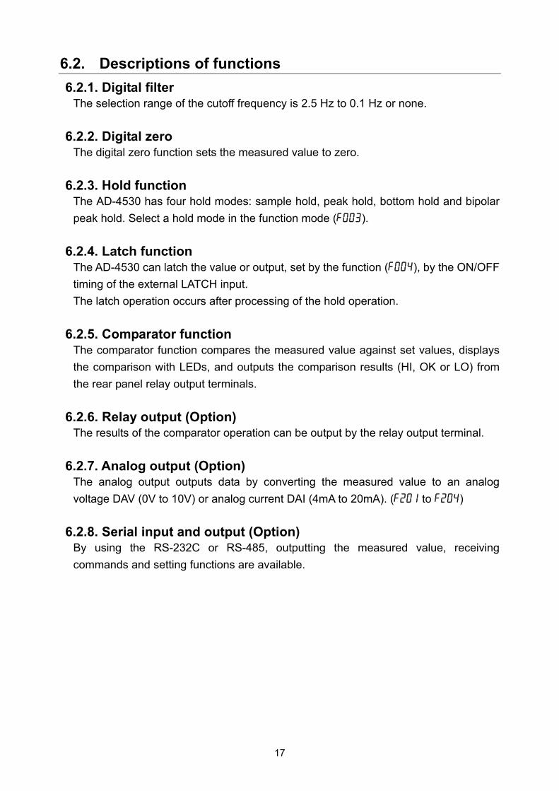
6.2. Descriptions of functions
6.2.1. Digital filter The selection range of the cutoff frequency is 2.5 Hz to 0.1 Hz or none.
6.2.2. Digital zero The digital zero function sets the measured value to zero.
6.2.3. Hold function The AD-4530 has four hold modes: sample hold, peak hold, bottom hold and bipolar
peak hold. Select a hold mode in the function mode (f003).
6.2.4. Latch function The AD-4530 can latch the value or output, set by the function (f004), by the ON/OFF
timing of the external LATCH input.
The latch operation occurs after processing of the hold operation.
6.2.5. Comparator function The comparator function compares the measured value against set values, displays
the comparison with LEDs, and outputs the comparison results (HI, OK or LO) from
the rear panel relay output terminals.
6.2.6. Relay output (Option) The results of the comparator operation can be output by the relay output terminal.
6.2.7. Analog output (Option) The analog output outputs data by converting the measured value to an analog
voltage DAV (0V to 10V) or analog current DAI (4mA to 20mA). (f201 to f204)
6.2.8. Serial input and output (Option) By using the RS-232C or RS-485, outputting the measured value, receiving
commands and setting functions are available.

18
7. CALIBRATION
The AD-4530 measures voltage signals from sensors and displays the values.
Calibration is performed so that the AD-4530 performs correctly.
The decimal point (Cf01), minimum scale value (Cf02) and rated capacity (Cf03) are
set using the function mode.
The zero point input voltage (Cf04), the span input voltage (Cf05) and the display value
for the span input voltage (Cf06) are set using the calibration mode.
Calibration setting by the function mode is also available. (Digital calibration)
* During calibration, maintain a stable environment to prevent calibration errors.
* You can confirm stabilization by confirming that the HOLD LED is on.
* The decimal point blinks to indicate that a number is being displayed, not a
measured value.
7.1. Calibration Modes
In the measurement mode, press the + keys to enter the calibration mode.
Enter the zero point calibration mode.
Return to the measurement mode.
7.1.1. Zero point calibration mode With nothing on the load cell, wait for it to stabilize, and then
press the key.
Perform zero point calibration, and
proceed to the span calibration mode.
Cancel zero point calibration, and
proceed to the span calibration mode.
Hold to display the mV/V of the zero point.
Span calibration

19
7.1.2. Span calibration mode Apply the actual load for span calibration to the load cell, and then input the value to be displayed when the load is applied. After stabilization, press the key.
Select the digit to be changed.
Increase the value of the digit to be changed.
Change the polarity.
Perform span calibration, and proceed to the storing mode.
Cancel span calibration, and proceed to the storing mode.
* After span calibration, the AD-4530 displays the mV/V value of span calibration for
3 seconds, and then proceeds to the storing mode.
7.1.3. Storing calibration mode Store the calibration zero, span and displayed value acquired.
When calibration was not performed, data is not stored.
Store the data acquired, and return to the measurement mode.
Do not store the data acquired, and return to the
measurement mode.
Storing mode
Measurement mode

20
7.2. Calibration Errors
Display Cause Remedy
C?e2 Voltage at zero point calibration was
too far in the positive direction.
C?e3 Voltage at zero point calibration was
too far in the negative direction.
Confirm the rating and connection
of the load cell.
C?e4 The value of the calibration weight
exceeds the rated capacity.
Use a proper calibration weight.
C?e5 The value of the calibration weight is
less than the minimum scale value.
Use a proper calibration weight.
C?e6 The load cell sensitivity is insufficient. Confirm the load cell connection.
Use a proper calibration weight.
C?e7 Voltage at span calibration is less
than the zero point.
Confirm the load cell connection.
C?e8
When adding a load of the rated
capacity, the load cell output voltage
is too high.
Use a load cell with a greater
rated capacity or set a smaller
rated capacity value.

21
8. FUNCTION MODE
Use the function mode to set various functions and data. The set values are saved in
non-volatile memory and are maintained even if the power is switched off.
8.1. Structure of Functions
The first 2 characters of the Function No. are the function group. The last 2 characters
of the Function No. are the function item. Cf Calibration function
f0 Basic function
f1 Comparator function
Use this function to set the comparator operation.
f2 Analog output function
Use this function to set the output value of the analog voltage output and
analog current output.
f3,f4 Serial communication function
Use this function to set the RS-232C and RS-485.
* Set the zero point input voltage (Cf04), the span input voltage (Cf05) and the display
value for the span input voltage (Cf06) in the calibration mode.
* Set the upper limit value (f101) and lower limit value (f102) in the comparator mode.
* When setting a function, the decimal point blinks to indicate that a number is being
displayed, not a measured value.
8.2. Key operation
In the measurement mode, press the + keys to enter the function selection mode.
8.2.1. Function selection mode
Select the function group. (First 2 characters)
Select the function item. (Last 2 characters)
Enter the setting changing mode.
Save the setting in non-volatile memory, and then return to the measurement mode.

22
8.2.2. Setting changing mode (Two methods)
P Parameter selection method (All digits blinking)
Change the parameter.
Enter the setting and return to the function selection mode.
Cancel the setting and return to the function selection mode.
D Digital input method (Change the blinking digit only)
Move the digit to be changed to the right.
Change the value of the blinking digit.
Change the polarity.
Enter the setting and return to the function selection mode.
Cancel the setting and return to the function selection mode.

23
8.3. Function Items
8.3.1. Calibration (C function) Function No. Setting range
Function Description Default valueSetting type
Cf01 0 to 3
Decimal point position
Decimal point position of the measured value: 0:0000 1:000.0 2:00.00 3:0.000
0 P
Cf02 1 to 50
Minimum scale value
Minimum division (d) of the measured value: 1:1 10:10 2:2 20:20 5:5 50:50
1 P
Cf03 1 to 9999
Rated capacity Measurement is possible up to the value of this setting plus 8 d (8 minimum divisions). Decimal point position depends on Cf01.
7000 D
Cf04 -7.000
to 7.000
Input voltage of zero point
Input voltage from the load cell at zero point. (Unit: mV/V)
0.000 D
Cf05 0.001
to 9.999
Input voltage of span
Input voltage from the load cell at span (measurement point - zero point). (Unit: mV/V)
7.000 D
Cf06 -9999
to 9999
Display value for input
voltage of span
Display value for span (measurement point - zero point). Decimal point position depends on Cf01.
7000 D
Cf07 0 to 100
Zero adjustment
range
Range to enable zero adjustment by the digital zero. Expressed in percent of the rated capacity with the calibration zero point as the center.
100 D
Cf08 0.0 to 5.0
Zero tracking time
Performed in combination with zero tracking width. (Unit: second) When 0.0, zero tracking is not performed.
0.0 D
Cf09 0.0 to 9.9
Zero tracking width
Performed in combination with zero tracking time. (Unit: 0.1 d) When 0.0, zero tracking is not performed.
0.0 D
Cf10 0 to 2
Power on zero
Digital zero when turning power on: 0: Digital zero off 1: Perform digital zero again 2: Use state when the power was turned off
0 P
Cf11 1 to 3
Zero operation
1: On with
2: On with +
3: On by pressing and holding for more than 1 second
* In all settings: When it is on, off with +
1 P
Cf12 1 to 2
Zero of the I/O input
1: On / Off depends on the I/O input. 2: Only digital zero on (no off)
1 P

24
8.3.2. Basic Function Function No.Setting range
Function Description Default valueSetting type
f001 0000
to 1111 Disable key
Each digit of the setting corresponds to a key switch. Only available in the measurement mode. Key assignment: 0: Enabled 0 0 0 0 1: Disabled
+
0000 (Binary)
D
f002 0 to 11
Digital filter
Cutoff frequency: 0: Off 6:0.5Hz 1:2.5 Hz 7:0.35 Hz 2:2.0 Hz 8:0.25 Hz 3:1.5 Hz 9:0.20 Hz 4:1.0 Hz 10:0.15 Hz 5:0.7 Hz 11:0.10 Hz
4 P
f003 0 to 4
Hold mode
0: Off 1: Sample hold 2: Peak hold 3: Bottom hold 4: Bipolar peak hold
1 P
f004 0000
to 1111
LATCH function
Function corresponds to an external input latch. Setting and latch Assignment: 0: Off 0 0 0 0 1: On
Display value latch Comparator latch Analog output latch Serial output latch
0000 (Binary)
D
*If you want to confirm the measured value when setting the digital filter (f002), press the
key.
When the measured value is displayed, the OK LED blinks and the display can be set
to zero by pressing the key.
Press the key to return the setting display.

25
8.3.3. Comparator Function No. Setting range
Function Description Default valueSetting type
f101 -9999 to
9999
Upper limit value
Upper limit value of comparator. Decimal point position depends on Cf01.
0000 D
f102 -9999 to
9999
Lower limit value
Lower limit value of comparator. Decimal point position depends on Cf01.
0000 D
f103 0 to 2
Comparator mode
0:Off 1:On when the measured value is not near
zero 2: Always on
2 P
f104 -9999 to
9999 Near zero
Set the near zero range for the comparator mode.
0000 D
f105 1 to 3
Hysteresis mode
Hysteresis direction: 1:Upward 2-level judgment 2:Upper / lower limit judgment 3:Downward 2-level judgment
2 P
f106 0.0 to 5.0
Hysteresis time
Set the hysteresis time by units of 0.1 seconds. When 0.0, the hysteresis is not used.
0.0 D
f107 00 to 99
Hysteresis width
Set the hysteresis width to a two-digit value. When 00, the hysteresis is not used.
99 D
8.3.4. Analog Function No. Setting range
Function Description Default valueSetting type
f201 -9999 to
9999 0 V output
Measured value at DAV 0V output. Decimal point position depends on Cf01.
0000 D
f202 -9999 to
9999 10 V output
Measured value at DAV 10V output. Decimal point position depends on Cf01.
1000 D
f203 -9999 to
9999 4 mA output
Measured value at DAI 4 mA output. Decimal point position depends on Cf01.
0000 D
f204 -9999 to
9999 20 mA output
Measured value at DAI 20 mA output. Decimal point position depends on Cf01.
1000 D

26
8.3.5. Serial Communication Function No.Setting range
Function Description Default valueSetting type
f301 2.4 to 38.4
Baud rate
2.4: 2400 bps 4.8: 4800 bps 9.6: 9600 bps 19.2:19200 bps 38.4:38400 bps
2.4 P
f302 7 to 8
Data bit length
7:7 bits 8:8 bits
7 P
f303 0 to 2
Parity 0:None 1: Odd 2: Even
2 P
f304 1 to 2
Stop bit 1:1 bit 2:2 bits
1 P
f305 1 to 2
Terminator 1:CRLF 2:CR
1 P
f306 1 to 2
Communication mode
1: Stream 2: Manual print
2 P
f307 00 to 99
Model No. ID that is added to the serial output. When setting is 00, the ID is not added.
00 D
f401 f402 f403 f404 f405 00 to 7F
Unit character1 Unit character2 Unit character3 Unit character4 Unit character5
Unit character added to serial output. Set with the hexadecimal ASCII code. All characters after 00 are ignored.
00 00 00 00 00
(Hexadecimal)D
8.3.6. Error Display Cause Remedy
ad?e The data cannot be acquired from
A/D converter.
Repair is required.
eepe
Correct data cannot be read from
EEPROM.
Perform initialization.
If the initialization does not clear the
error, repair is required.
Cale Calibration data error. Perform calibration.
C e* Calibration error. Refer to “7.2.Calibration Errors”.
dt?e A setting value is out of range. Check setting values and correct if
necessary.

27
8.3.7. ASCII code (20h~7Fh) Hexadecimal 00 01 02 03 04 05 06 07 08 09 0A 0B 0C 0D 0E 0F
20 SP ! " # $ % & ' ( ) * + , - . /
30 0 1 2 3 4 5 6 7 8 9 : ; < = > ?
40 @ A B C D E F G H I J K L M N O
50 P Q R S T U V W X Y Z [ \ ] ^ _
60 ` a b c d e f g h i j k l m n o
70 p q r s t u v w x y z | ~ DL
20 SP is space 7F DL is DEL

28
9. DIGITAL ZERO (DZ)
The digital zero function sets the measured value to zero. When measuring a load, it
can be used as the tare, etc.
While using this function, the DZ LED turns on.
9.1. Operating by key
When the key is pressed, the display is set to zero, and the DZ function is turned on.
If you want to turn the DZ function off, press the + keys.
* The operating procedure depends on the setting of (Cf11).
Press the + keys or press and hold the key for more than 1 second,
turn on the DZ function.
When it is turned on, the display is set to zero.
9.2. Operating by I/O input
Whether the DZ function is ON or OFF depends on the operation of the zero terminal of
the I/O input.
When the zero terminal is on (connected to the Com terminal), the DZ function is turned
on and the display is set to zero.
You can disable the digital zero off in the function mode (Cf12).
9.3. Zero tracking
Using the zero tracking function, the AD-4530 updates the zero point automatically by
sensing the zero point movement.
Zero tracking functions only when digital zero is turned on. Set the zero tracking time
(Cf08) and zero tracking width (Cf09) by setting the function.
* When the zero point is over the zero correction range, zero tracking is not performed.
* When refreshing the zero point using the zero tracking function, backup to non-volatile
memory will not be performed.
Display 0 Tracking width
Start
Tracking time

29
9.4. Power On Zero
Select the digital zero for when the power is turned on. (Cf10)
0: Digital zero off
Measurement is based on the zero point of the calibration.
Use with the measurement of an absolute value such as force measurement.
1: Perform digital zero again
Measurement is based on the zero point when the power is turned on.
Use with weight measurement etc. 2: Use the state when the power was turned off
Measurement is based on the DZ.
Use with measurements that require a long time such as a hopper scale.
It is a useful function in case of a power loss.
9.5. Backup of DZ
The DZ value is maintained in non-volatile memory (EEPROM).
Writing up to 10,000,000 times is available, so keep track of use frequency.
If the available DZ memory is 10% or less, the LED of the digital zero DZ blinks.
With the setting (Cf10=2), the backup memory is refreshed only when refreshed by key
operation or command.
(When refreshing the zero point using the zero tracking function, the backup memory is
not refreshed.)
DZon
Power supply
on
Power supply
off
Change of power supply
Change of input
0: Digital zero off
1: Perform digital zero again
2: Use state when
the power was turned off
0
0
0
0
ON
OFF
Change of display
Difference by setting

30
10. HOLD FUNCTION
The AD-4530 has four hold modes: sample hold, peak hold, bottom hold and bipolar
peak hold. A hold mode can be selected in the function mode (f003).
10.1. Basic function
Start the hold function by pressing the key, setting the hold terminal of the
external input to on, or a serial communication command.
10.1.1. Operation by using the key
Press the key. The hold function starts and the AD-4530 holds the displayed
value.
While the display is in the hold mode, pressing the key again cancels the hold
function, and the AD-4530 displays the measured value.
10.1.2. Operation using the external input hold terminal When the external hold input terminal is turned on (contact input), the hold function
starts.
To hold the displayed value at this time, keep the external input hold terminal in the on
state.
To cancel the display hold, set the external input hold terminal to the off state.
10.1.3. Operation using a serial communication command The hold function is started by the hold on command “HC
RLF” of the serial
communication and is canceled by the hold off command “CCR
LF”.
10.2. Hold indicator
The AD-4530 displays that it is in the hold state by turning the HOLD LED on.
10.3. Priority when inputting hold
When inputting a hold, the external input hold terminal has a higher priority than any
other operation.
10.4. Over value during hold
If the value is over during the hold, the display is blank.
Ensure that a function with non-displayed data, such as the comparator or output, is
processed based on the hold data.

31
10.5. Hold Modes
10.5.1. Sample hold mode Holds the display and output when receiving a hold input.
10.5.2. Peak hold mode Holds the peak value when receiving a hold input.
Sensor inputDisplayed value
ON OFF
ON OFF
HOLD key
External hold input During the holding operation, HOLD turns on.
Sensor input
Displayed value
ON OFF
ON OFF
HOLD key
External hold input During the holding operation, HOLD turns on.

32
10.5.3. Bottom hold mode Holds the bottom value when receiving a hold input.
10.5.4. Bipolar peak hold mode Holds the absolute peak value when receiving a hold input.
Sensor inputDisplayed value
ON OFF
ON OFF
HOLD key
External hold input During the holding operation,
HOLD turns on.
Sensor input
Displayed value
ON OFF
ON OFF HOLD key
External hold input During the holding operation, HOLD turns on.

33
11. LATCH
The AD-4530 can latch the value and output that are set by the function (f004) in
response to the external latch input.
With regard to the output, first the hold operation is processed, then the latch operation.
Sensor inputOutput value
ON OFF External latch input
During the latching operation.

34
12. COMPARATOR FUNCTION
The comparator function compares the measured value against the set values, and the
results are displayed by the LEDs. If the relay option is installed, it outputs the
comparison results (HI, OK or LO) from the rear panel relay output terminals.
12.1. Detailed description of the comparator mode
The relation between the comparison outputs and the upper and lower limit setting
values is as shown below:
Comparison result Comparison condition
HI Upper limit < Measured value
OK Lower limit Measured value Upper limit
LO Measured value < Lower limit
* HI is output with a positive over limit, LO is output with a negative over limit.
Upper limit and lower limit values can be negative.
For example, if the upper limit value is -1000 and the lower limit value is -2000, HI is
output for the measured value of -500 and LO is output for the measured value of -2500.
Make sure that the upper limit value is greater than the lower limit value.
12.2. Setting the upper and lower limit value
Set the upper limit value (f101) and lower limit value (f102) of the function using the
following procedure. In the measurement mode, press the or key to enter
the setting mode for the upper or lower limit value.
In the setting mode for the upper or lower limit value, the AD-4530 blinks the HI or LO
LED. (The relay output is not affected.)
The setting value is displayed. Set the value by operating the key.
Shift the blinking digit to the value to be changed.
Change the value of the blinking digit.
Change the polarity.
Store the setting, and return to the measurement mode.
Cancel the setting, and return to the measurement mode.
HI OK LO
Measurement mode
Measurement mode

35
* If a key is not pressed within 20 seconds in the upper or lower limit setting mode, the
AD-4530 will cancel the setting, and return to the measurement mode.
* The decimal point blinks to indicate that a number is being displayed, not a measured
value.
12.3. Example of the comparator mode
Continuous comparison excluding the zero band
12.4. Hysteresis
A hysteresis width and time is provided for the output relay on/off timing to prevent the
output terminals from chattering.
When the measured value exceeds the set value, the relay is turned on. If the
measured value falls below the set value and it is further reduced by the hysteresis
width, or if the hysteresis time has elapsed, the relay is turned off.
The hysteresis mode, time and width can be set in the function modes (f105 to f107).
ONOFF
ON OFF
ON OFF
Upper limit
Lower limit
Zero band
HI output
OK output
LO output

36
12.4.1. Hysteresis upward 2-level judgment (f105=1) Relation between HI and OK
When the measured value exceeds the set upper limit value, HI is output
immediately. Even if the measured value falls below the upper limit value, OK is not
output immediately. OK will be output when the measured value falls below the
hysteresis width, or when the hysteresis time has been exceeded.
Relation between LO and OK
When the measured value exceeds the set lower limit value, OK is output
immediately.
Even if the measured value falls below the lower limit value, LO is not output
immediately. LO will be output when the measured value falls below the hysteresis
width, or when the hysteresis time has been exceeded.
Judgment example
Hysteresis width
Hi
lo
HI output
OK output
LO output
ONOFF
ON OFF
ON OFF
Hysteresis time
37
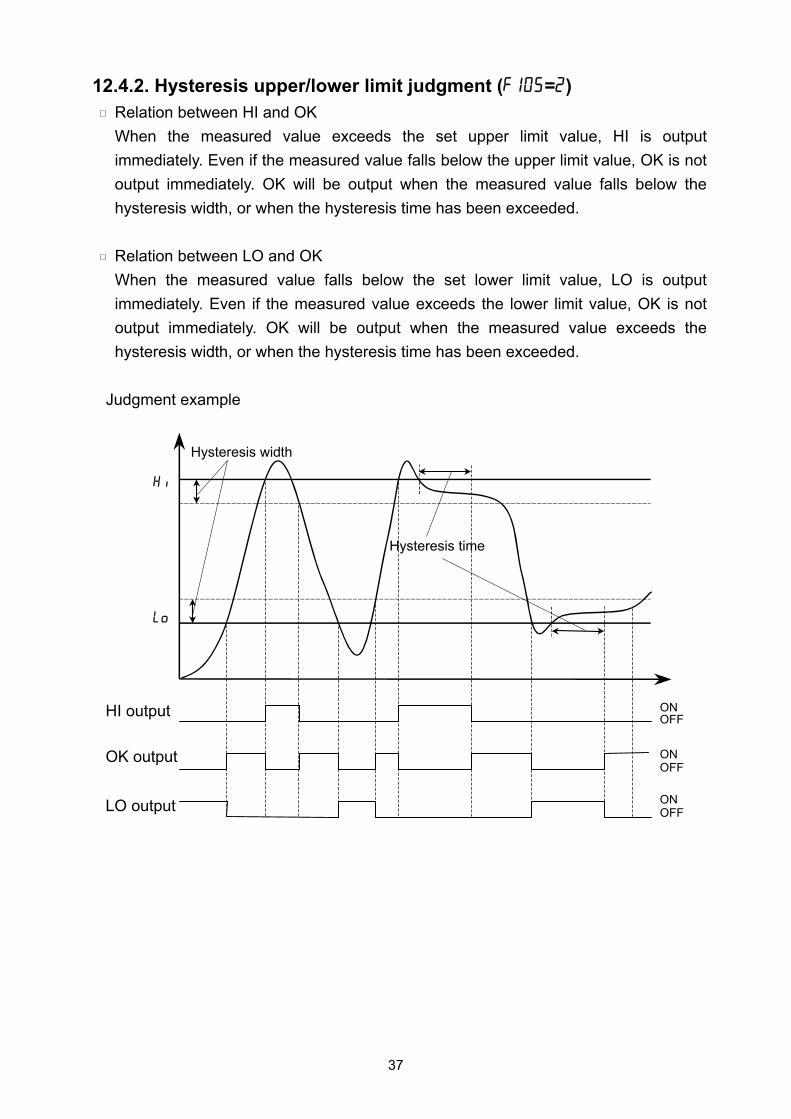
12.4.2. Hysteresis upper/lower limit judgment (f105=2) Relation between HI and OK
When the measured value exceeds the set upper limit value, HI is output
immediately. Even if the measured value falls below the upper limit value, OK is not
output immediately. OK will be output when the measured value falls below the
hysteresis width, or when the hysteresis time has been exceeded.
Relation between LO and OK
When the measured value falls below the set lower limit value, LO is output
immediately. Even if the measured value exceeds the lower limit value, OK is not
output immediately. OK will be output when the measured value exceeds the
hysteresis width, or when the hysteresis time has been exceeded.
Judgment example
Hysteresis width
Hi
lo
HI output
OK output
LO output
ONOFF
ON OFF ON OFF
Hysteresis time

38
12.4.3. Hysteresis downward 2-level judgment (f105=3) Relation between HI and OK
When the measured value falls below the set upper limit value, OK is output
immediately.
Even if the measured value exceeds the upper limit value, HI is not output
immediately. HI will be output when the measured value exceeds the hysteresis
width, or when the hysteresis time has been exceeded.
Relation between LO and OK
When the measured value falls below the set lower limit value, LO is output
immediately. Even if the measured value exceeds the lower limit value, OK is not
output immediately. OK will be output when the measured value exceeds the
hysteresis width, or when the hysteresis time has been exceeded.
Judgment example
Hysteresis width
Hi
lo
HI output
OK output
LO output
ONOFF
ON OFF ON OFF
Hysteresis time

39
13. ANALOG OUTPUT
The analog output outputs data by converting the measured value to an analog voltage
DAV (0V to 10V) or an analog current DAI (4mA to 20mA). (f201 to f204)
13.1. Analog voltage DAV (0V to 10V)
13.2. Analog current DAI (4mA to 20mA)
10V
0V
Output voltage
f202b f201a f202a
f201b Measured value
b a
20mA
4mA
Output current
f204b f203a f204a
f203b Measured value
b a

40
14. SERIAL INPUT AND OUTPUT
14.1. Data output format
Normal measured value WT, ±12.34CR
LF
No decimal point WT, ±01234CR
LF
When over limit OL, ±99.99CR
LF
When adding the instrument number @NNWT, ±12.34CR
LF
(NN is the number set with f307)
When adding the unit WT, ±12.34UUUUUCR
LF
(U is the character code set with f401 to f405)
14.2. Command or response
When receiving an incorrect command, the response is “?”. When a command cannot
be performed, the response is “I”.
When adding the instrument identification number (ID), add “@NN” (NN is the number
set with f307) before the command. In a case where the command does not have the
“@NN”, or is an incorrect number, there will be no response. The “@NN” precedes the
response.
14.2.1. Data request Output the display data of when receiving the command.
Command R
Command example RCR
LF
Response example WT,±12.34CR
LF
For details about the response, refer to “14.1. Data output format”.
14.2.2. Zero command Perform zero operation.
Command Z
Command example ZCR
LF
Response example ZCR
LF
14.2.3. Hold ON command Start the hold function.
Command H
Command example HCR
LF
Response example HCR
LF

41
14.2.4. Hold OFF command Cancel the hold function.
Command C
Command example CCR
LF
Response example CCR
LF
14.2.5. CAL zero command Set the input voltage (Cf04) at the zero point of the CAL using the input data when
receiving the command.
Command CZ
Command example CZCR
LF
Response example CZCR
LF
14.2.6. CAL span command Set the input voltage (Cf05) at the span of the CAL using the input data when
receiving the command.
Command CS
Command example CSCR
LF
Response example CSCR
LF
14.2.7. Function reading command Confirm the function setting.
The query “?” function number is four characters.
Command example ?F123CR
LF
Response example F123,±4567CR
LF
14.2.8. Function setting command Change the function setting.
The function number is four characters and the polarity and setting value is four
characters.
Command example F123,±4567CR
LF
Response example F123,±4567CR
LF

42
15. MAINTENANCE
15.1. Error display
When an error is displayed, perform the appropriate remedy.
Display Cause Remedy
ad?e The data cannot be acquired from
A/D converter.
Repair is required.
eepe
Correct data cannot be read from
EEPROM.
Perform initialization.
If the initialization does not clear the
error, repair is required.
Cale Calibration data error. Perform calibration.
C e* Calibration error. Refer to “7.2.Calibration Errors”.
dt?e A setting value is out of range. Check setting values and correct if
necessary.
Display Cause Remedy
C?e2 Voltage at zero point calibration was
too far in the positive direction.
C?e3 Voltage at zero point calibration was
too far in the negative direction.
Confirm the rating and connection of
the load cell.
C?e4 The value of the calibration weight
exceeds the rated capacity.
Use a proper calibration weight.
C?e5
The value of the calibration weight
is less than the minimum scale
value.
Use a proper calibration weight.
C?e6 The load cell sensitivity is insufficient. Confirm the load cell connection.
Use a proper calibration weight.
C?e7 Voltage at span calibration is less
than the zero point.
Confirm the load cell connection.
C?e8
When adding a load of the rated
capacity, the load cell output voltage
is too high.
Use a load cell with a greater rated
capacity or set a smaller rated
capacity value.

43
15.2. Checking operation
To confirm the operation of the display, key switch and external input and output. Use
the check mode.
* The decimal point blinks to indicate that a number is being displayed, not a measured
value.
15.2.1. Entering check mode (Selection mode)
In the measurement mode, press the + +
keys to enter the selection mode for the check mode.
Change the item to be checked.
Enter the check mode.
Return to the measurement mode.
15.2.2. Checking the display Check the display by turning on each segment and the individual
LEDs.
All on / Turn on by digit / Turn on by segment
Change the item to be checked. (All on, digit, segment)
Proceed to the selection mode. (Refer to “15.2.1”)
15.2.3. Checking the version Display the ROM version of the AD-4530 .
Proceed to the selection mode. (Refer to “15.2.1”)
Selection mode
Selection mode
Measurement mode
To check mode
Mode name
Enter
Selection mode

44
15.2.4. Checking A/D conversion (mV/V) Check by displaying the input voltage as mV/V.
Set the display to zero.
Proceed to the selection mode. (Refer to “15.2.1”)
15.2.5. Checking DAV voltage Check the D/A output voltage in 1V steps.
Increase the output voltage in 1V steps.
(The step after 10V is 0V.)
Proceed to the fine adjustment mode.
(When 0V or 10V, hold for 5 seconds.)
Proceed to the selection mode. (Refer to “15.2.1”)
* The output voltage can be finely adjusted using the
fine adjustment mode.
15.2.6. Checking DAI current Check the D/A current output in 2 mA steps.
Increase the output current in 2 mA steps.
(The next step after 20 mA is 4 mA.)
Proceed to the fine adjustment mode.
(When 4 mA or 20 mA, press for 5 seconds.)
Proceed to the selection mode. (Refer to “15.2.1”)
* The output voltage can be finely adjusted using the
fine adjustment mode.
Selection mode
Fine adjustment
mode
Or
Selection mode
Or
Fine adjustment
mode
Selection mode

45
* Fine adjustment mode The available adjustment unit is 0.001V for DAV voltage and 0.001mA for DAI current.
When adjusting the 0V or 4mA, the LO LED blinks.
When adjusting the 10V or 20mA, the HI LED blinks.
Select the adjustment range. (The digit of the range
to be adjusted blinks.)
Increase the output within the adjustment range. (If the blinking digit is 9, the next digit is 0, and the value of the next significant digit is increased.)
Decrease the output with the adjustment range. (If the blinking digit is 0, the next digit is 9, and the value of the next significant digit is decreased.)
Set and save the output.
Back
During fine adjustment, be sure to base measurements on a high
precision voltmeter and milliamp meter. Otherwise, an error in the
output value of the AD-4530 may occur.
15.2.7. Checking I/O Check the control input and comparator output.
Ones ON/OFF(1/0) of ZERO input
Tens ON/OFF(1/0) of HOLD input
Hundreds ON/OFF(1/0) of LATCH input
HI output and HI blinking
OK output and OK blinking
LO output and LO blinking
Proceed to the selection mode. (Refer to “15.2.1”)
Back
Selection mode
CAUTION
!

46
15.2.8. Checking the serial data Check the serial input and output. (RS-232C/RS-485)
“WT,4530”is output with the stream or manual print mode.
When receiving the“R”command, OK turns on.
Switch between the stream mode ( HI is turned
on) or manual print mode ( LO is turned on).
While this key is pressed, the baud rate of the
setting is displayed.
While this key is pressed, the data bit length, parity, stop bit and terminator of the setting is displayed.
Output the data.
Proceed to the selection mode. (Refer to “15.2.1”)
15.2.9. Checking the keys Check the state of each key.
Ones
Tens
Hundreds
Thousands
Turn on the minus LED. (If you want to proceed to
the selection mode, press this key twice quickly.)
15.2.10. Checking the DZ memory Check by displaying how much space is available in DZ
memory as a percentage.
Proceed to selection mode. (Refer to “15.2.1”)
HI OK LO
Setting valuedisplay
Output
Selection mode
Selection mode
Selection mode
Press twice
47
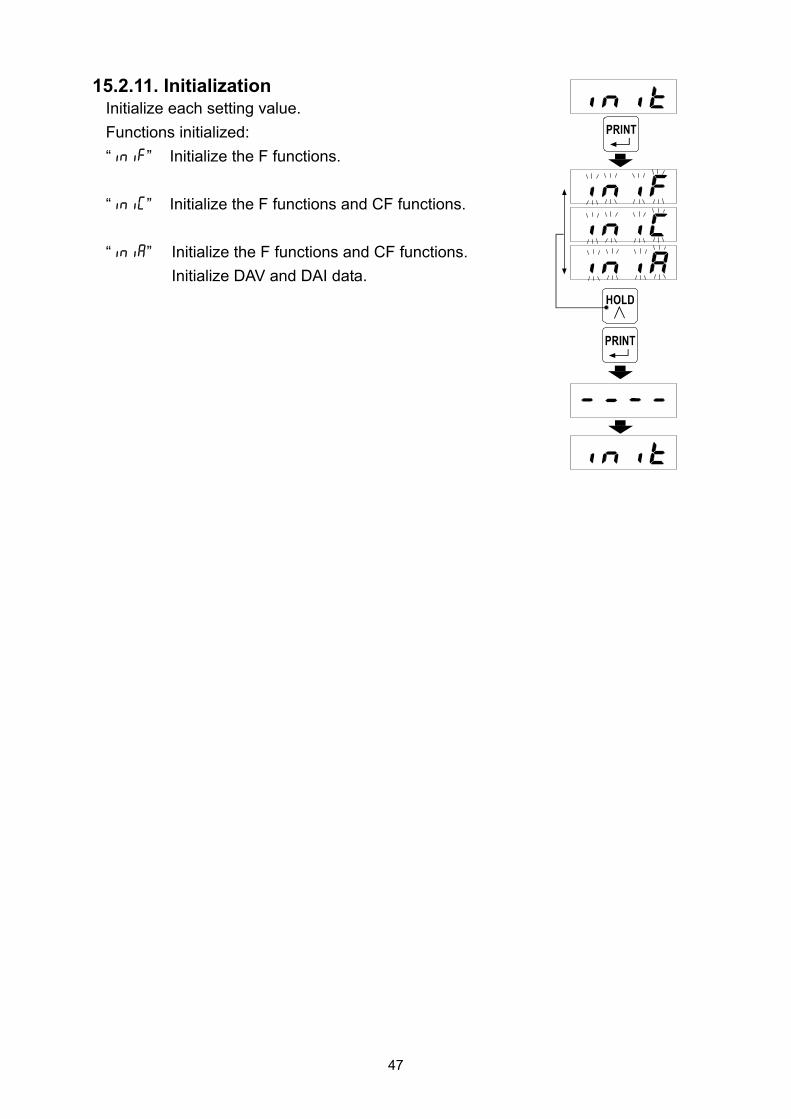
15.2.11. Initialization Initialize each setting value.
Functions initialized:
“inif” Initialize the F functions.
“iniC” Initialize the F functions and CF functions.
“inia” Initialize the F functions and CF functions.
Initialize DAV and DAI data.

48
16. SETTING LIST
When performing maintenance, use the following list as a memo.
When inquiring about the product, mention the user settings.
16.1. Calibration (C function)
Function No. Setting range
Description Default value User setting
Cf01 0 to 3
Decimal point position 10n digit. 0
Cf02 1 to 50
Minimum division; 1:1 10:10 2:2 20:20 5:5 50:50
1
Cf03 1 to 9999
Rated capacity. 7000
Cf04 -7.000 to 7.000
Input voltage from the load cell at zero point..mV/V
0.000
Cf05 0.001 to 9.999
Input voltage from the load cell at span. .mV/V
7.000
Cf06 -9999 to 9999
Display value for span. 7000
Cf07 0 to 100
Zero adjustment range. Expressed in percent of the rated capacitywith the calibration zero point as the center.
100
Cf08 0.0 to 5.0
Zero tracking time. (Unit: second) When 0.0, zero tracking is not performed.
0.0
Cf09 0.0 to 9.9
Zero tracking width. (Unit: 0.1 d) When 0.0, zero tracking is not performed.
0.0
Cf10 0 to 2
Power on zero: 0: Digital zero off 1: Perform digital zero again 2: Use state when the power was turned off
0
Cf11
1 to 3
Zero operation:
1: On with
2: On with
+
3: On by pressing and holding for more than 1 second
* In all settings: When it is on, off with +
1
Cf12 1 to 2
Zero of the I/O input: 1: On / Off depends on the I/O input. 2: Only digital zero on (no off)
1

49
16.2. Basic Functions
Function No. Setting range
Description Default value User setting
f001 0000 to 1111
Disable keys: 0: Enabled 1: Disabled
0000 (Binary)
f002 0 to 11
Digital filter: 0: Off 6:0.5 Hz 1:2.5 Hz 7:0.35 Hz 2:2.0 Hz 8:0.25 Hz 3:1.5 Hz 9:0.20 Hz 4:1.0 Hz 10:0.15 Hz 5:0.7 Hz 11:0.10 Hz
4
f003 0 to 4
Hold mode: 0: Off 1: Sample hold 2: Peak hold 3: Bottom hold 4: Bipolar peak hold
1
f004 0000 to 1111
LATCH function: 0: Off 1: On
0000 (Binary)
16.3. Comparator
Function No. Setting range
Description Default value User setting
f101 -9999 to 9999
Upper limit value of comparator. 0000
f102 -9999 to 9999
Lower limit value of comparator. 0000
f103 0 to 2
Comparator mode: 0:Off 1:On when the measured value is not
near zero 2:Always on
2
f104 -9999 to 9999
Set the near zero range for the comparator mode.
0000
f105 1 to 3
Hysteresis direction: 1:Upward 2-level judgment 2:Upper / lower limit judgment 3:Downward 2-level judgment
2
f106 0.0 to 5.0
Hysteresis time. (Unit: 0.1 second) When 0.0, the hysteresis is not used.
0.0
f107 00 to 99
Hysteresis width. (d) When 00, the hysteresis is not used.
99

50
16.4. Analog
Function No. Setting range
Description Default value User setting
f201 -9999 to 9999
DAV 0V output 0000
f202 -9999 to 9999
DAV 10V output 1000
f203 -9999 to 9999
DAI 4 mA output 0000
f204 -9999 to 9999
DAI 20 mA output 1000
16.5. Serial Communication
Function No. Setting range
Description Default value User setting
f301 2.4 to 38.4
Baud rate: 2.4: 2400 bps 4.8: 4800 bps 9.6: 9600 bps 19.2:19200 bps 38.4:38400 bps
2.4
f302 7 to 8
Data bit length: 7:7 bits 8:8 bits
7
f303 0 to 2
Parity: 0:None 1: Odd 2: Even
2
f304 1 to 2
Stop bit: 1:1 bit 2:2 bits
1
f305 1 to 2
Terminator: 1:CRLF 2:CR
1
f306 1 to 2
Communication mode: 1: Stream 2: Manual print
1
f307 00 to 99
Model No. When set to 00, the ID is not added.
00
f401 f402 f403 f404 f405 00 to 7F
Unit character (5 character) All characters after 00 are ignored.
00 00 00 00 00
(Hexadecimal)

51
17. EXTERNAL DIMENSIONS
Panel cutout dimensions / Separation *Maintain the intervals above when installing
UNIT: mm
94.8
96
48
44.6
120
(139
.1)
7.5
AD-4530
HI OK LO
DZ
HOLD
HI+/-
HOLDLOESC
ZERO
45+
0.6
-0
92 +0.8-0
MIN. 120
MIN
. 70

52
MEMO


3-23-14 Higashi-Ikebukuro, Toshima-ku, Tokyo 170-0013, JAPAN Telephone: [81] (3) 5391-6132 Fax: [81] (3) 5391-6148 A&D ENGINEERING, INC. 1756 Automation Parkway, San Jose, California 95131, U.S.A. Telephone: [1] (408) 263-5333 Fax: [1] (408)263-0119 A&D INSTRUMENTS LIMITED Unit 24/26 Blacklands Way, Abingdon Business Park, Abingdon, Oxfordshire OX14 1DY United KingdoTelephone: [44] (1235) 550420 Fax: [44] (1235) 550485 A&D AUSTRALASIA PTY LTD 32 Dew Street, Thebarton, South Australia 5031, AUSTRALIA Telephone: [61] (8) 8301-8100 Fax: [61] (8) 8352-7409 A&D KOREA Limited 한국에이.엔.디(주) 대한민국 서울시 영등포구 여의도동 36-2 맨하탄 빌딩 8층 우편 번호 150-749 ( Manhattan Building 8th Floor, 36-2 Yoido-dong, Youngdeungpo-gu, Seoul, 150-749 Korea ) 전화: [82] (2) 780-4101 팩스: [82] (2) 782-4280 OOO A&D RUS OOO "ЭЙ энд ДИ РУС" 121357, Российская Федерация, г.Москва, ул. Верейская, дом 17 ( Business-Center "Vereyskaya Plaza-2" 121357, Russian Federation, Moscow, Vereyskaya Street 17 ) тел.: [7] (495) 937-33-44 факс: [7] (495) 937-55-66 A&D INSTRUMENTS INDIA PRIVATE LIMITED
( 509, Udyog Vihar, Phase- , Gurgaon - 122 016, Haryana, India )
: 91-124-4715555 : 91-124-4715599