JEDI Slides Intro1 Chapter 11 Inheritance Polymorphism Interf

With the JPS ACU-1000modular interf a c e /interconnect system, a radiorouter system can be configured to meet almostany interf a c eapplication involving telephones and radios.
ACU-1000 Modular Interface/Interconnect S y s t e m
INTRODUCTIONWith the JPS ACU-1000 modularinterface/interconnect system, a radio routersystem can be configured to meet almost anyinterface application involving telephones andradios. The system is suitable for HF, LandMobile Radio, and SATCOM systems and offersessentially unlimited applications and expand-ability as a Radio Branch Exchange. Adding anew communications format to the system can be as simple as plugging in the appropriateinterface module and connecting the newequipment to the ACU-1000 backplane.
GENERALThe main purpose of the ACU-1000 is to provide interconnections between differentcommunications systems. The ACU-1000 can simultaneously cross-band two or moredifferent radio networks, connect a radio network to a telephone line (or SATCOM system), or even create a conference callbetween several different radio networks and a caller on the telephone line. An operator atthe ACU-1000 can use the HSP-2 module tomonitor or establish an interconnection withany (or all) of the communications systemsthat are wired to the ACU-1000 rear panel. The ACU-1000 provides voice and toneprompts to assist all system users in makingfull use of all of the unit’s capabilities.
Each of the 12 interface module plug-in slotsmay contain a module that will connect a communications system to the rest of the ACU-1000 network. Each of these plug-in slots is given an extension number, from 01through 12; the module installed in the plug-inslot just to the right of the CPM-1 module isgiven extension number 01, and extensionnumber 12 is associated with the right-mostslot. In an Expanded System, plug-in slots 1 through 12 on the Slave Chassis are givenextension numbers 13 through 24. The HSP-2module has extension number 00 (think of thisas similar to “0” for “Operator”). In an
Expanded System, the HSP-2 in the SlaveChassis has the extension 25.
INTERFACE MODULES– FUNCTIONS AND OPERATIONSUp to twelve interface modules may be installedalong with the basic chassis modules. Theseinterface modules allow a wide variety of differ-ent communications media to become part ofthe ACU-1000 system: HF, UHF, VHF, 800 MHzand trunking radios; Satellite users; distantcallers connected via the PSTN; local callersconnected by a standard telephone set; cellphone users; and fax machines. These andalmost any type of two-wire or four-wire communications media can be connected.Users gain entry to the system and exercisecontrol over the ACU-1000 and the call thatthey’ve made via DTMF operational commands.The different interface modules are describedbriefly below.
HSP-2 HANDSET/SPEAKER/PROMPTM O D U L EThe HSP-2 Module provides a means to locally monitor, configure and control an ACU-1000 system. The user can monitor audiovia an internal speaker (or plug in an externalspeaker), or use a set of headphones or thehandset that comes with the HSP-2. The handset includes a PTT switch to allow the userto key a cross-connected radio via the HSP-2.Module control and configuration is made via a3x4 keypad (standard telephone layout). Thiskeypad can be used to select a system moduleand enter control or configuration data for thatmodule. The HSP-2 may also be used to setconfiguration parameters (input and output levels, for example) of all system modules.
In addition to the front-panel handset andphones jacks, the HSP-2 has input and outputaudio lines (0 dBm nominal), an external micro-phone input and an external speaker output. All system voice prompt circuitry resides on the HSP-2’s piggyback board.
A P P L I C ATION NOTES
JPS Communications, Inc.5800 Departure DriveRaleigh, NC 27616
Phone: (919) 790-1011Fax: (919) 790-1456E-Mail: [email protected]: www.jps.com
Specifications subject to change without notice.Copyright © 2003 JPS Communications. All rights reserved.
Ver.1 6/03

A P P L I C ATION NOTESACU-1000 Modular Interface/Interconnect S y s t e m
RDI-1 MODULE
The RDI-1, along with the DSP-1 module, interfaces the ACU-1000 system to radios and other four-wire devices. It contains circuits to interface balanced or unbalanced 600-ohmaudio to a transmitter and from a receiver, and has audio leveladjustments for both. The balanced send and receive audiointerface is also available for a remote control head or console.It has a DTMF receiver/generator and a built-in low-speed synchronous modem suitable for transferring telephone numbersor selective calling codes over HF or VHF. It also contains an RS-232 asynchronous serial port for control of radios or otherdevices. This module also includes a transmit PTT driver andreceiver COR/COS input, as well as two uncommitted controlinputs and two uncommitted control outputs.
DSP-1 ModuleThe DSP-1, along with the RDI-1 module, is a 4-wire interface
to the ACU-1000 system and can interface radios, remote controlheads, or other 4-wire audio devices. It contains circuits to interface balanced or unbalanced 600-ohm audio from a receiver,600 ohm balanced audio to a transmitter, and has audio leveladjustments for both. The balanced send and receive audiointerface is also available for a remote control head or console.The DSP-1 is similar to the RDI-1 module in that it is used tointerface radios and other 4-wire devices. Due to the DSP circuitry and signal processing algorithms on the DSP-1, it contains functions that the RDI-1 does not, such as three typesof COR: Hardware signal, VMR, and VOX. It also offers a DSPnoise reduction mode, audio high-end equalization and an overdrive limiter. The VMR and Noise Reduction capability makeit an ideal HF radio interface. Unlike the RDI-1, the DSP-1 has no serial port.
PSTN-1 ModuleThe PSTN-1 Module is the 2-wire interface between the ACU system and a telephone system (as opposed to a telephone set).A telephone system is an entity that accepts dialing informationand processes calls, such as a PSTN line, PABX line, InmarsatTerminal, or cellular phone. (A telephone set is a device thatgenerates dialing information such as a standard telephone thatcan be locally purchased and plugged into a standard wall jack.Telephone sets are interfaced to the ACU system via the LP-1Module.) Two modular jacks are available on the PSTN-1 frontpanel, allowing a pair of two-wire devices to be connected; however only one can be active at a time. The module also has a 4-wire port for interfacing to 4-wire phone lines or otherdevices. It also contains ring detect and Caller ID circuitry forautomated system operation.
The PSTN-1’s /AUX01 output (pin 12) changes logic state duringring cadence, intended to control an external ringer. When theSTU-III function is enabled, this output also changes states todrive the optional STU-III telephone interface box.
Among the functions provided by the PSTN-1’s DSP algorithmsare a DSP hybrid, a VOX with configurable sensitivity and hangtime, and a DTMF receiver/generator for control and callprogress recognition.
The two 2-wire ports are available via two front-panel RJ-11Cjacks. Internal jumpers may be used to route these signals to make them available at the associated ACU-1000 backplaneconnector.
LP-1 ModuleThe LP-1, Local Phone Module, is the interface to the ACU system for 2-wire devices, which generate dialing informationsuch as a telephone set or FAX machine. This module contains a loop current generator, ring voltage generator, dial and busytone generators, a DSP hybrid with VOX and a DTMFgenerator/receiver. In addition to interfacing a telephone set into the ACU system, this module can be used as a telephone“line card” in a mini-PBX system.
AP-1 ModuleThe AP-1 module is a general-purpose 4-wire module that canprovide a variety of DSP operations. Unlike other ACU-1000modules, the AP-1 does not communicate with the system audioand control bus structures on the ACU-1000 backplane. The AP-1 is “In Series” with the audio signal that is routed through itvia the associated rear panel connector. The ACU-1000 chassismerely provides to the AP-1s DC power and a place to reside.The DSP functions of the AP-1 can operate either on the audioand control signal coming into the ACU-1000 module that it isassociated with it (AP-1 RX Option Assembly), or on the audioand control signal that is exiting the associated ACU-1000 mod-ule (AP-1 TX Option Assembly). Alternatively, the AP-1’s DSPfeatures can be used to modify signals not associated at all withthe ACU-1000.
Operating ScenariosACU-1000 Application:Operating Scenario, TwoModules Interconnected
Please reference Figure 1: HF to UHF/VHF RetransmissionSystem Using ACU-1000.
The purpose of the ACU-1000 is to transfer transmit and receiveaudio from one port or piece of equipment to another port orpiece of equipment. This scenario will help in the understandingof how the ACU-1000 performs this task.
Attached to the DSP-1 module (module 1) on the left is an HFtransmitter and HF Receiver, both connecting to P1. Attached to the DSP-1 module (module 2) on the right is an UHF/VHFtransceiver connected to P2. When in the unconnected state,neither of the DSP-1 modules is attached to the audio busses ofthe ACU-1000. In Figure 1, both the DSP modules are intercon-nected, attached to the busses of the ACU-1000, allowing RX

A P P L I C ATION NOTESACU-1000 Modular Interface/Interconnect S y s t e m
audio from module 1 to drive the TX audio of module 2. Inreverse, the RX audio from module 2 drives the TX audio ofmodule 1. Observing Figure 1, this means the audio in from theHF RCVR is routed to the UHF/VHF transmit out, and theUHF/VHF receive signal is routed to the HF XMTR output. Thisgives the user an HF to UHF/VHF interconnect. When a usersends a signal to the HF unit, the user on the UHF/VHF hears thesignal as though it were a UHF/VHF originated signal. When auser sends a signal to the UHF/VHF unit, the user on the HFhears the signal as though it were an HF originated signal. In aduplex system, both these paths are active at the same time. In a simplex or half duplex system, the CPM controls the gates onboth modules to allow only one direction or path to be active at a time. The CPM knows when or how to do this by COR. COR is discussed in the following paragraph. The audio bus connec-tions and management are controlled by the CPM, which is driven by user input either by the HSP-2 keypad entry’s, or by the Console Interface Software commands.
CORThe DSP-1 and RDI-1 modules must have positive knowledge an input audio signal is present so they know when to key anassociated transmitter. A signal that provides this information is called COR (for Carrier Operated Relay, sometimes referred to as COS Carrier Operated Squelch). The RDI-1 can handlehardware COR signals only, but the DSP-1 module can use anexternal hardware COR line, an internal VMR (Voice ModulationRecognition) algorithm, or a VOX Squelch. In a full duplex connection, it may be desirable to ignore COR activity altogetherand never mute the incoming audio. The correct selectionsdepend on the type of radio or other equipment that is connectedto the DSP-1 receive audio input.
· FM Radios- For best reliability, use a hardware COR signal, if one is available from the radio’s own squelch circuit. If nohardware COR signal is available, and the radio has a squelch circuit, use the radio’s squelch in conjunction with VOX mode.VMR should be used for FM radios that must be operated withan open squelch (receiver noise is present when there is no signal). The VOX cannot be used in this condition because it will open on receiver noise, while the VMR opens only onspeech, not on receiver noise. When used in this mode, theVMR threshold must be set to Med2 or High to avoid falsing on white noise from the FM discriminator.
· AM Aircraft Radios- Again, the best choice is a hardwareCOR line from the radio, if one is available. If this isn’t an option,VMR should be used. VMR thresholds of Low or Med1 may bemost appropriate for this application.
· HF SSB Radios- The only reliable choice for HF radios isVMR. VMR thresholds of Low or Med1 may be most appropriatefor this application.
· Non-Radio Applications- The choice for these applica-
tions is hardware COR, if this signal is available. If not, use VOXif the audio is relatively noise-free; use VMR for noisy signals.
ACU-1000 Application:Operating Scenario, VHFRepeater, UHF and HF System
Please reference Figure 2: ACU-1000 System Interfacing HFReceiver/Exciter pair, VHF Repeater and UHF Transceiver toInmarsat Terminal or PSTN.
This drawing portrays the ability of the ACU-1000 to interface different media systems. With the ACU-1000, all the attachedmediums may be interconnected together in any configuration.For example, the UHF transceiver may be connected to the PSTN-1 module and routed to the Inmarsat unit allowing the UHF radio users to talk via the Inmarsat to phone users. Thephone users may talk via the UHF radio as though they were an UHF radio user. At the same time, the HF receiver and trans-mitter may be connected to the VHF Repeater, allowing HF usersto be repeated out the VHF Repeater, and all VHF users using therepeater would be transmitted out the HF as well. Both thesescenarios can occur at the same instant, the UHF connected tothe PSTN and the HF connected to the VHF Repeater, withoutcross talk or interference. Each one of these interconnections is called a Net in the ACU-1000. The ACU-1000 is capable ofconducting seven nets at the same instant. The limit of sevennets is due to the amount of Audio Busses available in the ACU-1000. The maximum of seven nets may be conducted at the same time without cross talk or interference between thenets. Please see the following paragraph on Audio Busses.
Audio Bus ManagementIn the ACU-1000, the audio is routed via audio busses and issteered by the CPM. There are 16 audio busses available foruse. One of these busses is reserved for the Voice Prompts.This leaves 15 audio busses available to the CPM to route the possible audio combinations. Audio busses are utilized as follows:
When connecting two modules together in a Net, two audiobusses are utilized. This allows the RX audio of one module to be placed as the TX audio of the other module. Please referencethe following drawing:
When connecting a third module to the system above, it willoccupy one more audio bus. The deciding factor for how manyaudio busses are being used is based on one audio bus for everymodule in a net. For the example above, with a third module connected, there will be three audio busses taken by the net,
A P P L I C ATION NOTESACU-1000 Modular Interface/Interconnect S y s t e m
and one audio bus taken by the voice prompts. This means there are still 12 audio busses remaining for use. In a systemwith a full compliment of 12 interface modules, it is not possibleto run out of audio busses. There may be up to a possible sixnets limited only by the 12 available modules; this utilizes 12busses with an additional bus for the Voice Prompts, creating 13 used busses. In a Master/Slave system, where two ACU-1000chassis’s are used to create a possible 24 available modules, themaximum number of nets of seven can be reached, limited bythe 16 available busses.
ACU-1000 Application:Operating Scenario, RadioPABX Providing Interconnect for Three Radios andTwo Phone Lines
Please reference Figure 3: ACU-1000 Application, Radio PABXProviding Interconnect for Three Radios and Two Phone Lines
This system represents the capability of the ACU-1000 to be aPABX for both radios and phone lines. Included in this systemare a SATCOM unit, two phones via the PSTN connections, acell phone, a VHF radio, a UHF radio and HF radio. Any user,whether entering the system via any of the PSTN phone lines, orvia any radio attached, has the capability of connecting to anyother user or module. This can most easily be described as aRadio/Phone PABX.
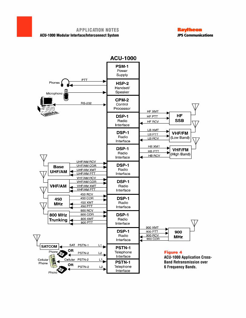
ACU-1000 Application:Operating Scenario, Cross-Band Retransmission over Six Frequency Bands
Please reference Figure 4: ACU-1000 Application, Cross-BandRetransmission over Six Frequency Bands
The system represents the capability of the ACU-1000 to cross-band connect multiple radios and phones in a large interconnect.By placing all modules in the same net, there is a large intercon-nect including HF, VHF/FM low band, VHF/FM high band, 900 MHz, UHF/AM, VHF/AM, 450 MHz, 800 MHz and phoneconnections. When any module begins to receive COR, the othermodules all go into the transmit mode and send that signal outthe transmit path to all users in the field for that module.
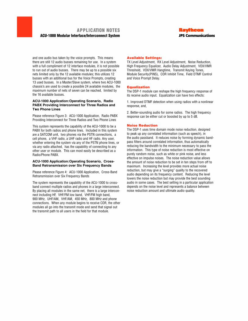
Available Settings:TX Level Adjustment, RX Level Adjustment, Noise Reduction,High Frequency Equalizer, Audio Delay Adjustment, VOX/VMRThreshold, VOX/VMR Hangtime, Transmit Keying Tones,Module Security(PINS), COR Inhibit Time, Field DTMF Controland Voice Prompt Delay.
EqualizationThe DSP-1 module can reshape the high frequency response ofits receive audio input. Equalization can have two effects:
1. Improved DTMF detection when using radios with a nonlinearresponse, and,
2. Better-sounding audio for some radios. The high frequencyresponse can be either cut or boosted by up to 5 dB.
Noise ReductionThe DSP-1 uses time domain mode noise reduction, designed to peak up any correlated information (such as speech), in the audio passband. It reduces noise by forming dynamic band-pass filters around correlated information, thus automaticallyreducing the bandwidth to the minimum necessary to pass theinformation. This type of noise reduction is most effective onpurely random noise, such as white or pink noise, and less effective on impulse noises. The noise reduction value allows the amount of noise reduction to be set in ten steps from off tomaximum. Increasing the level provides more actual noisereduction, but may give a “surging” quality to the recoveredaudio depending on its frequency content. Reducing the levellowers the noise reduction but may provide the best soundingaudio in some cases. The best setting in a particular applicationdepends on the noise level and represents a balance betweennoise reduction amount and ultimate audio quality.

A P P L I C ATION NOTESACU-1000 Modular Interface/Interconnect S y s t e m

A P P L I C ATION NOTESACU-1000 Modular Interface/Interconnect S y s t e m
Figure 2ACU-1000 System Interfacing HFReceiver/ Exciter Pair, VHFRepeater and UHF Transceiver toINMARSAT Terminal or PSTN.

A P P L I C ATION NOTESACU-1000 Modular Interface/Interconnect S y s t e m
Figure 3ACU-1000 PABX applicationproviding interconnect for 3 radios and 2 phone lines.
A P P L I C ATION NOTESACU-1000 Modular Interface/Interconnect S y s t e m
Figure 4ACU-1000 Application Cross-Band Retransmission over 6 Frequency Bands.