
Educationmedia.knex.com/education/teachers-guides/78600-TG-Exploring... · the activity and sets...
74
78600 78600 Education ® TEACHER’S GUIDE EXPLORING MACHINES
Transcript of Educationmedia.knex.com/education/teachers-guides/78600-TG-Exploring... · the activity and sets...
78600 78600
Education®
TEACHER’SGUIDE
EXPLORING MACHINES
EXPLORING MACHINESTeacher’s Guide
Call us at 888-ABC-KNEX
Education®1
V3-8/14©2014 K’NEX Limited Partnership Group and its licensors.
K’NEX Limited Partnership GroupP.O. Box 700Hatfield, PA 19440-0700
K’NEX Education is a registered trademark of K’NEX Limited Partnership Group.Protected by International Copyright. All rights reserved.
Visit our website at www.knexeducation.comEmail: [email protected]: 1-888-ABC-KNEX (Toll Free)
A NOTE ABOUT SAFETY:Safety is of primary concern in science and technology classrooms. It is recommended that you develop a set of rules that governs the safe, proper use of K’NEX in your classroom. Safety, as it relates to the use of the Rubber Bands should be specifically addressed.
CAUTIONS:Students should not overstretch or overwind their Rubber Bands. Overstretching and over-winding can cause the Rubber Band to snap and cause personal injury. Any wear and tear or deterioration of Rubber Bands should be reported immediately to the teacher. Teachers and students should inspect Rubber Bands for deterioration before each experiment.
Caution students to keep hands and hair away from all moving parts. Never put fingers in mov-ing Gears or other moving parts.
WARNING:CHOKING HAZARD – Small parts. Not for children under 3 years.
ATTENTION :RISQUE D’ÉTOUFFEMENT – Pièces de petite taille. Ne convient pas aux enfants de moins de 3 ans.
IntroductionThe K’NEX® Exploring Machines set and the investigations included in the accompanying Teacher’s Guide are designed to support middle school physical science and technology curricula. Every attempt has been made to move from standard knowledge-based questioning to investigation, experimentation, and inquiry. Questions associated with each investigation are designed to help students develop higher order thinking skills. In physical science, in particular, this often means incorporating math skills and it also means asking students to analyze, synthesize, and at times, evaluate information.
Building Instruction Booklet #2 for the models that can be built with the set, but which are not highlighted in the Teacher’s Guide. These additional models can be used for challenges, further study, or for performance assessment tasks.
The Teacher’s Guide includes Student Inquiry Sheets and Worksheets for thirteen of the models found in Building Instruction Booklet #1. Each Inquiry Sheet identifies the objectives of the activity, lists the materials needed to carry out the investigation, presents background information about the simple machine that is the focus of the activity and sets out the procedure students should follow as they undertake their inquiry. Each Student Worksheet provides space for recording observations, asks additional questions about the machine being investigated and presents challenges that can be used to help students think more deeply about the concepts involved. Teachers should reproduce the Student Inquiry Sheets and Worksheets for their classes. Answers to questions can be found in the Teacher’s Answer Sheets which are located at the end of the guide.
Exploring�Machines
The K’NEX® Exploring Machines set is intended to help develop students’ understanding of the scientific concepts associated with simple machines. The set allows four groups of students to work simultaneously on the same model in the classroom. Alternatively, groups can work on different models as they rotate through a series of stations. Building Instructions are provided for 30 different models. The models highlighted in the Teacher’s Guide can be found in Building Instruction Booklet #1; four copies of this booklet accompany each set. The set also includes one copy of
exploring machines
www.knexeducat ion.com
2Education®
TABLE OF CONTENTSenrich the experiences with simple machines. The following suggestions may also be helpful:
• Use the building portion of each investigation as an introduction for new topics or concepts.
• Use building and investigation por-tions together as culminating laboratory activities for each simple machine.
• Set aside two or three days to be used as investigation days at the end of a section on a specific type of machine, such as levers. Have students rotate through stations and investigations that illustrate different types of levers. Include one or several stations that have models without investigations (from Booklet #2) and have students use their newly gained knowledge and understanding to identify the simple machine. For example, a series of lever investigations might include a balance station and a hammer station. Additional stations without investiga-tions might also include the rowboat (first-class lever) station, a nutcracker (second-class lever) station, and a fishing pole (third-class lever) station.
• If students keep a record of their observations and investigations in a science journal, use this as a means of assessment. Alternatively, have students keep student sheets in a designated lab folder for assessment and note keeping purposes. Teachers
Teaching StrategiesStudent Inquiry and Worksheets
Balance
Tow Truck
Block and Tackle
Elevator
Screwdriver
Paddlewheel Boat
Dump Truck
Inclined Plane
Archimedes’ Screw
Conveyor Belt
Rack and Pinion
Crank Fan
Carousel
Transmission
Teacher’s Answer Sheets
Exploring�Machines
Teaching Strategies:
The best way to administer the investigations provided in this Teacher’s Guide will be determined by the teacher, the nature of the classes, the curricu-lum goals, and national, state, and local standards. As teachers review their science standards they may gain additional insight into how to further
Call us at 888-ABC-KNEX
3 Education®
may be needed. Using this example, the screwdriver bag should contain the K’NEX components, together with a ruler, string, and weights.
• Practice building the proposed model in advance. Experience with each model allows one to troubleshoot those areas where students are most likely to encounter difficulty. Resist the urge to help students through difficult building challenges too quickly. Students should work through these challenges as a group. This will enhance their problem solving skills.
• Provide containers. Provide student groups with some means of confining the pieces to the desktop. Cafeteria trays or flat bottom boxes with low sides, such as the type used to transport soda cans, allow students to have building materials on the desktop without worrying that pieces will roll away and get lost. Similarly, transparent or translucent cups or beakers are a great way to keep track of the smallest pieces.
• Have groups sort their materials before building. Every set of building instructions lists a total number for each part needed to construct the model. Having the materials spread out in a tray allows students to classify and count their materials quickly and to check that they have all the pieces they need before they begin to build the model.
Exploring�Machines
at Alden Middle School, Alden, New York, who field-tested the Exploring Machines materials with their seventh and eighth grade classes, offered the following practical suggestions:
• If the teacher would rather have students record their observations and data in individual science journals, the student worksheets can be omitted. The classroom teacher can use the questions found on these worksheets as a starting point for guided inquiry. With this approach, the teacher can tailor the investigations to better suit individual classroom or curriculum needs.
• Laminate building instructions. This will ensure that the building instructions survive from class to class and from year to year.
• Assemble model kits in advance. The K’NEX Exploring Machines set arrives with the components partially presorted into a compartmentalized box. To prepare for an investigation, locate one set of building and investigation instructions. Each building instruction includes an itemized list of the parts needed to build a specific machine. To avoid confusion, place the necessary components for a particular machine set in a zipper sealed bag. For example, if the class is going to undertake the screwdriver investigation, assemble four screwdriver sets. Each set should be placed in its own zipper sealed plastic bag with any additional materials that
exploring machines
www.knexeducat ion.com
4Education®
Exploring�Machines
• Have students read before build-ing. Encourage students to highlight or underline the information that they believe will be most important in the “What’s the Story?” section. This helps focus their attention and is a basic study skill.
• Show students how to connect the pieces. Although some students may be familiar with K’NEX, others probably are not. Use an overhead projector to show a class how to connect most types of pieces or refer them to pertinent information about the various K’NEX connections in their Building Instructions booklets. Students can then be encouraged to build the first model in Building Booklet #1, a hammer, as a practice model. This will ensure that those with no previous experience with K’NEX become familiar with the different parts and the techniques for connecting them.
• Review often. Introduce each activity with a review of relevant concepts and vocabulary such as “Work,” “Force,” “Energy,” “Distance,” and the relation-ships between these and the machines that they have already explored. Many of the machine models resemble common items with which students may already be familiar. Encourage students to bring in, or suggest, other machines that are also examples of the machines they are studying in the classroom.
• Encourage students to work cooperatively. Suggest that students use their notes and discuss within their groups questions and ideas that are raised during the investigations.
Call us at 888-ABC-KNEX
5 Education®
The Balance student inq
uiry sheet
Objectives• To determine experimentally the relation- ships between effort force, load force, and fulcrum in a first-class lever system.
• To compare the mechanical advantage of different first-class lever systems.
• To design a first-class lever system that uses minimal effort force to balance the greatest load.
Materials• K’NEX Exploring Machines: Balance model
The following items are not included in the set:
• Pennies minted after 1982 (approx. 20 - 30)• 2 paper squares (7.5 cm x 7.5 cm), or weighing boats • Ruler • Small paper cup to store the pennies • Dot stickers or masking tape• Pen/marker
What’s the Story?
Machines allow you to do work faster or more easily. In other words, a machine helps you to do work. Machines can transfer energy, magnify force, multiply speed, or change the direction of a force. They cannot, however, increase work or energy. In most cases, the amount of work put into the machine is more than the amount of work produced by the machine. Because friction is present in most systems, some energy is changed to heat or sound.
Different types of machines offer different levels of mechanical advantages. Mechanical advantage is the ratio of the output force, or force exerted by the machine, to the input force, or force applied to the machine. A nail is difficult to pull out of wood with your hand because you cannot apply enough force to the nail to overcome friction. The same small force, however, applied to the end of a claw hammer handle, produces a larger force, applied over a small distance, at the hammer head. The output force of the hammer is large enough to overcome friction, allowing you to pull out the nail.
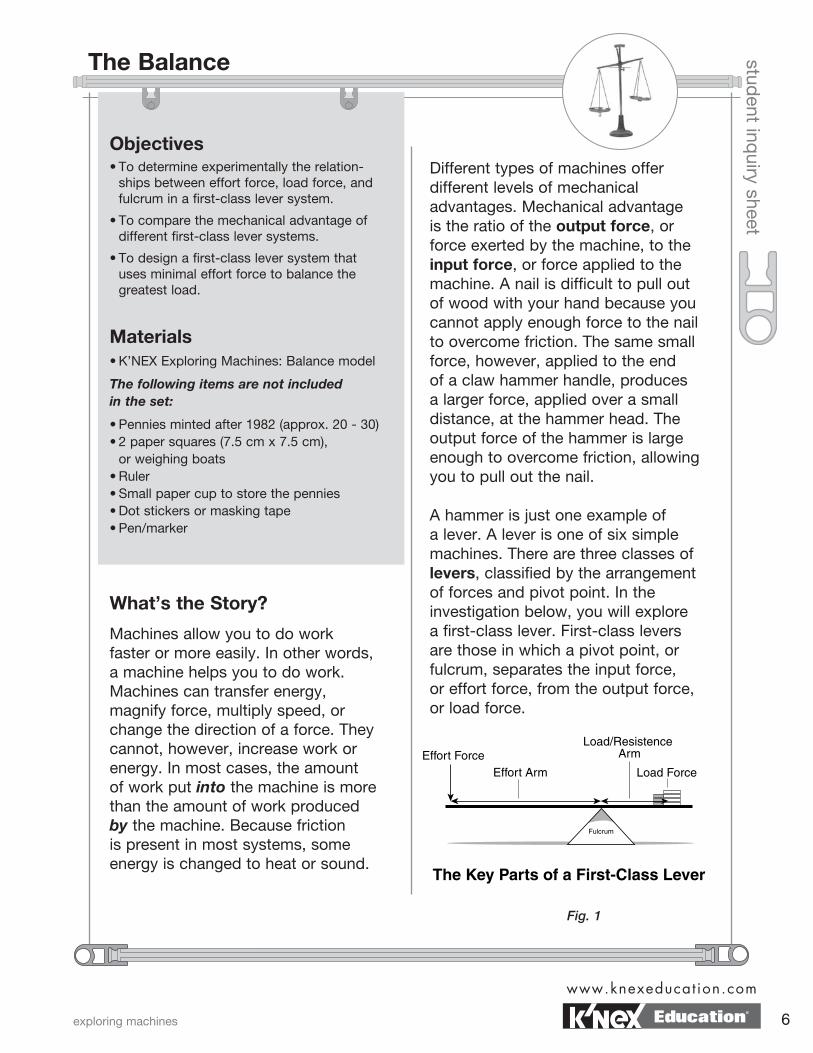
A hammer is just one example of a lever. A lever is one of six simple machines. There are three classes of levers, classified by the arrangement of forces and pivot point. In the investigation below, you will explore a first-class lever. First-class levers are those in which a pivot point, or fulcrum, separates the input force, or effort force, from the output force, or load force.
Fig. 1
exploring machines
www.knexeducat ion.com
6Education®
The Balance page 2 student inq
uiry sheet
What To Do Part I: All Things Being Equal
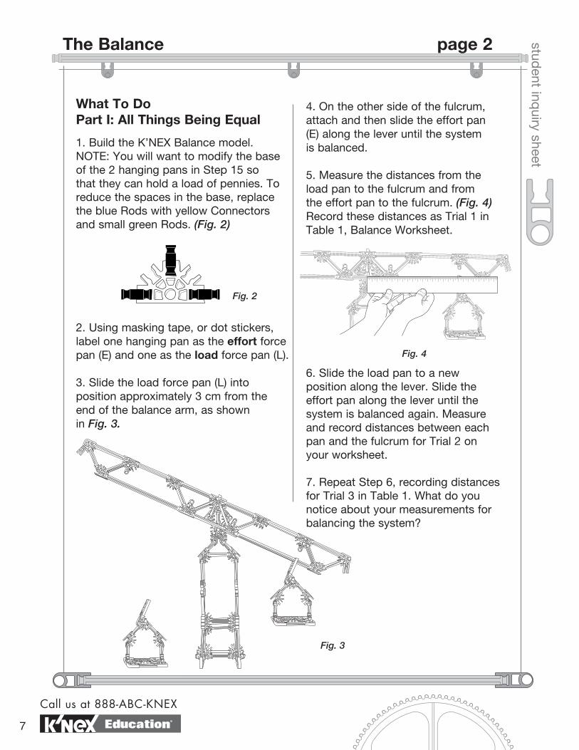
1. Build the K’NEX Balance model. NOTE: You will want to modify the base of the 2 hanging pans in Step 15 so that they can hold a load of pennies. To reduce the spaces in the base, replace the blue Rods with yellow Connectors and small green Rods. (Fig. 2)
2. Using masking tape, or dot stickers, label one hanging pan as the effort force pan (E) and one as the load force pan (L).
3. Slide the load force pan (L) into position approximately 3 cm from the end of the balance arm, as shown in Fig. 3.
4. On the other side of the fulcrum, attach and then slide the effort pan (E) along the lever until the system is balanced.
5. Measure the distances from the load pan to the fulcrum and from the effort pan to the fulcrum. (Fig. 4) Record these distances as Trial 1 in Table 1, Balance Worksheet.
6. Slide the load pan to a new position along the lever. Slide the effort pan along the lever until the system is balanced again. Measure and record distances between each pan and the fulcrum for Trial 2 on your worksheet.
7. Repeat Step 6, recording distances for Trial 3 in Table 1. What do you notice about your measurements for balancing the system?
Fig. 2
Fig. 3
Fig. 4
Call us at 888-ABC-KNEX
7 Education®
student inq
uiry sheet
8. Calculate and record the mechanical advantage (MA) for each trial. (The formula for MA, provided in Table 1, is the ratio of effort distance to load distance. In ideal circumstances this is the same as the ratio of output force to input force discussed earlier.)
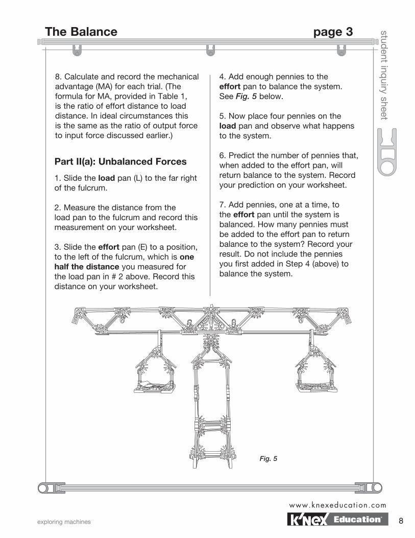
Part II(a): Unbalanced Forces
1. Slide the load pan (L) to the far right of the fulcrum.
2. Measure the distance from the load pan to the fulcrum and record this measurement on your worksheet.
3. Slide the effort pan (E) to a position, to the left of the fulcrum, which is one half the distance you measured for the load pan in # 2 above. Record this distance on your worksheet.
4. Add enough pennies to the effort pan to balance the system. See Fig. 5 below.
5. Now place four pennies on the load pan and observe what happens to the system. 6. Predict the number of pennies that, when added to the effort pan, will return balance to the system. Record your prediction on your worksheet.
7. Add pennies, one at a time, to the effort pan until the system is balanced. How many pennies must be added to the effort pan to return balance to the system? Record your result. Do not include the pennies you first added in Step 4 (above) to balance the system.
Fig. 5
exploring machines
www.knexeducat ion.com
8
The Balance page 3
Education®
student inq
uiry sheet
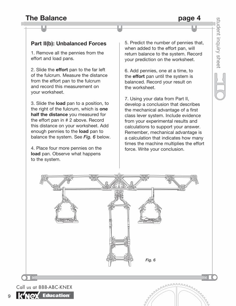
Part II(b): Unbalanced Forces
1. Remove all the pennies from the effort and load pans.
2. Slide the effort pan to the far left of the fulcrum. Measure the distance from the effort pan to the fulcrum and record this measurement on your worksheet.
3. Slide the load pan to a position, to the right of the fulcrum, which is one half the distance you measured for the effort pan in # 2 above. Record this distance on your worksheet. Add enough pennies to the load pan to balance the system. See Fig. 6 below.
4. Place four more pennies on the load pan. Observe what happens to the system.
5. Predict the number of pennies that, when added to the effort pan, will return balance to the system. Record your prediction on the worksheet.
6. Add pennies, one at a time, to the effort pan until the system is balanced. Record your result on the worksheet. 7. Using your data from Part II, develop a conclusion that describes the mechanical advantage of a first class lever system. Include evidence from your experimental results and calculations to support your answer. Remember, mechanical advantage is a calculation that indicates how many times the machine multiplies the effort force. Write your conclusion.
Fig. 6
Call us at 888-ABC-KNEX
9
The Balance page 4
Education®
Balance Worksheet
datenamestud
ent worksheet
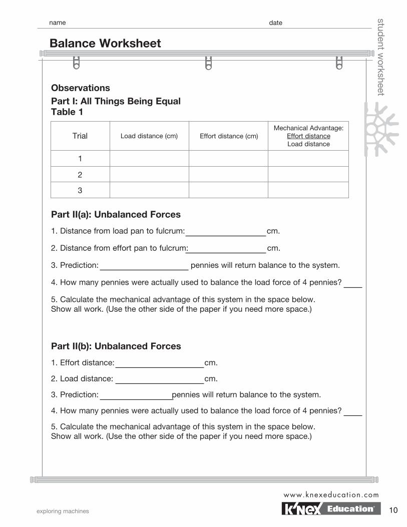
Part I: All Things Being Equal Table 1
Part II(a): Unbalanced Forces
1. Distance from load pan to fulcrum: cm.
2. Distance from effort pan to fulcrum: cm.
3. Prediction: pennies will return balance to the system.
4. How many pennies were actually used to balance the load force of 4 pennies?
5. Calculate the mechanical advantage of this system in the space below. Show all work. (Use the other side of the paper if you need more space.)
Part II(b): Unbalanced Forces
1. Effort distance: cm.
2. Load distance: cm.
3. Prediction: pennies will return balance to the system.
4. How many pennies were actually used to balance the load force of 4 pennies?
5. Calculate the mechanical advantage of this system in the space below. Show all work. (Use the other side of the paper if you need more space.)
Observations
Load distance (cm)
2
3
Effort distance (cm)Trial
1
Mechanical Advantage:Effort distance Load distance
exploring machines
www.knexeducat ion.com
10Education®
datenamestud
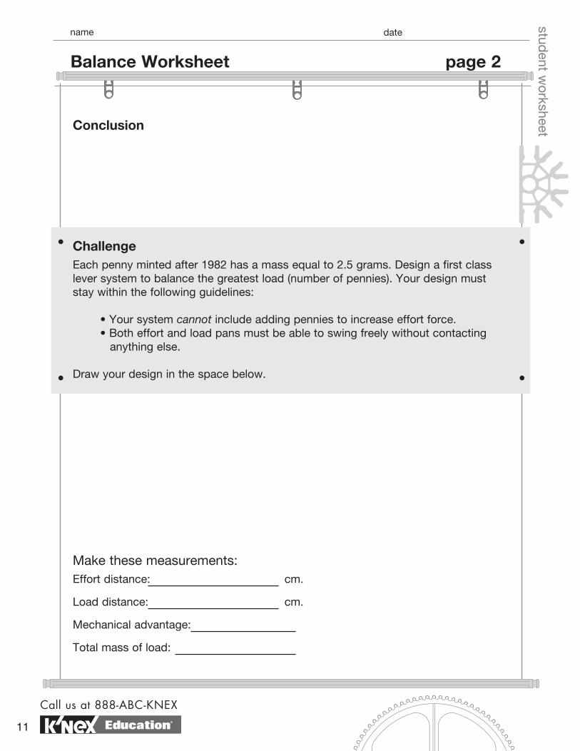
ent worksheetConclusion
ChallengeEach penny minted after 1982 has a mass equal to 2.5 grams. Design a first class lever system to balance the greatest load (number of pennies). Your design must stay within the following guidelines:
• Your system cannot include adding pennies to increase effort force. • Both effort and load pans must be able to swing freely without contacting anything else.
Draw your design in the space below.
Make these measurements:Effort distance: cm.
Load distance: cm.
Mechanical advantage:
Total mass of load:
Call us at 888-ABC-KNEX
11
Balance Worksheet page 2
Education®
Objectives• To observe a handle acting as a wheel turning an axle.
• To collect data for a wheel and axle system that models a common machine.
• To determine mathematically the effort force needed to lift a load.
Materials• K’NEX Exploring Machines: Tow Truck model
The following items are not included in the set:
• Spring scale • Fishing sinkers or other weights
What’s the Story?
A wheel and axle is a simple machine that transfers energy in a single motion. A wheel and axle is made up of two wheels of different size that turn together. An effort force applied to one wheel is transferred to the other wheel. A winch is a wheel and axle made up of two long, thin wheels called cylinders. The handle, or crank, traces out one cylinder. The shaft is the other cylinder. The mechanical advantage of a wheel and axle is calculated using the formula shown below.
student inq
uiry sheet
Getting Started
1. Using the building instructions, build the K’NEX Tow Truck model.
2. Tie the weights to the hook on the tow truck line.
3. While holding the towline, roll the tow truck to the edge of the desk. Allow the weights to drop to the floor.
4. Use the crank to wind the towline and retrieve the weights.
A rope or chain attached to the shaft is used to move a load. How can the mechanical advantage of a winch be used to calculate the size of the effort force needed to move a load? Do the following activity to find out.
effort radiusload radius
MA =
exploring machines
www.knexeducat ion.com
12
Tow Truck
Education®
student inq
uiry sheet
What To Do
1. Attach a spring scale to the weights and lift the weights to the height of the pulley on the tow truck. Record the load force on the Tow Truck Worksheet.
2. Measure the radius of the wheel to which the effort is applied. The radius of the wheel is the distance from the center of the shaft (red Rod) to the center of the handle’s shaft (blue Rod). Record this measurement - the effort radius of the wheel - on the Tow Truck Worksheet.
3. Measure the load radius of the axle. To do this, measure the diameter of the shaft. Calculate the radius by dividing the diameter by 2. Record the load radius of the shaft axle on the Tow Truck Worksheet.
4. To calculate the mechanical advantage (MA) of your winch, divide the effort radi-us by the load radius. Record the MA on the Tow Truck Worksheet.
5. Complete the questions on your worksheet.
notes
Call us at 888-ABC-KNEX
13
Tow Truck page 2
Education®
datenamestud
ent worksheet
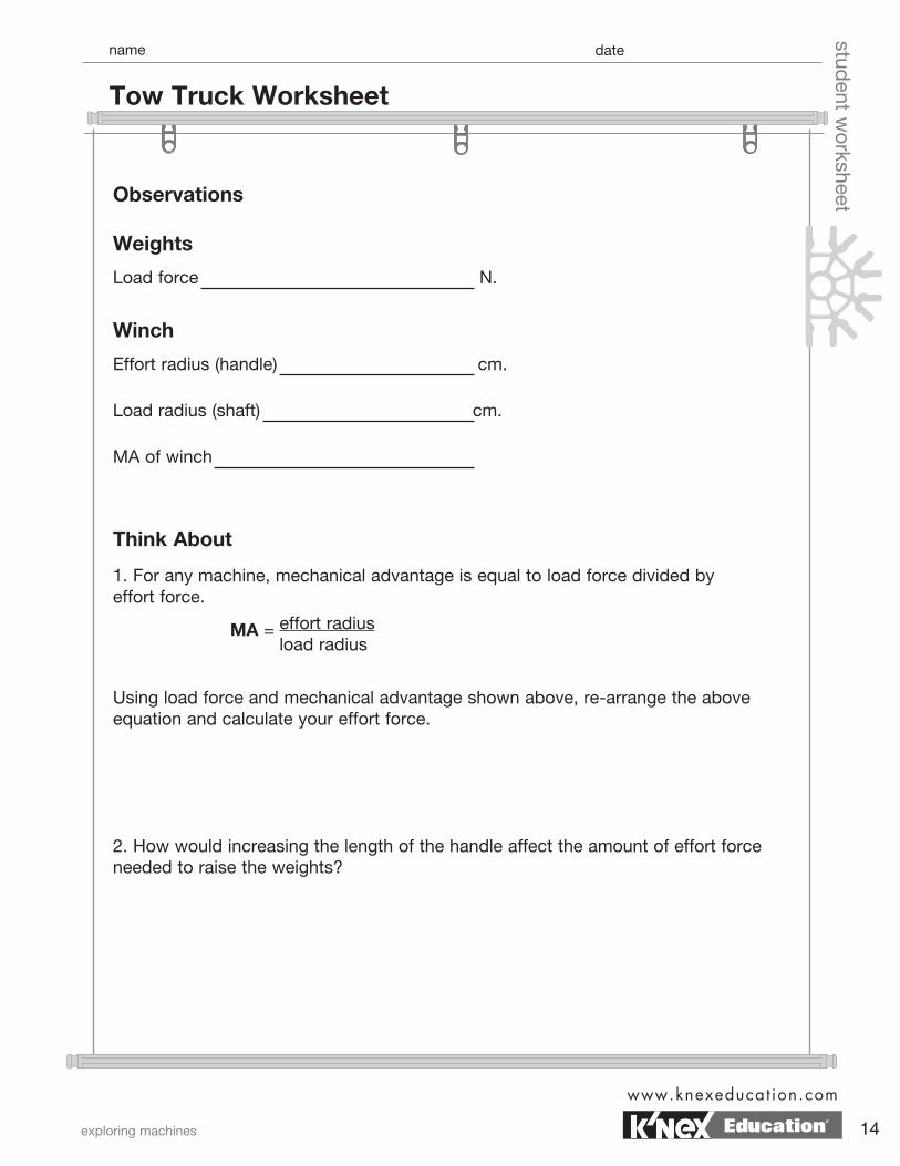
Weights
Load force N.
Think About
1. For any machine, mechanical advantage is equal to load force divided by effort force.
Winch
Effort radius (handle) cm.
Load radius (shaft) cm.
MA of winch
Using load force and mechanical advantage shown above, re-arrange the above equation and calculate your effort force.
2. How would increasing the length of the handle affect the amount of effort force needed to raise the weights?
Observations
effort radiusload radius
MA =
exploring machines
www.knexeducat ion.com
14
Tow Truck Worksheet
Education®
ChallengeA treasure chest weighing 300 N is found. You can exert a force of 30 N. Design a winch to raise the treasure chest. You will power the winch. Show all work in the space provided below.
datenamestud
ent worksheet3. You are to design a winch to pick up a load. A person turning the handle, rather
than a motor, will operate your winch. List three pieces of information that you will need to know to help you design the winch. You may write these as questions.
Call us at 888-ABC-KNEX
15
Tow Truck Worksheet page 2
Education®
student inq
uiry sheet
Objectives• To explore the mechanical advantage of a block and tackle system.
• To measure experimentally work input and work output of a block and tackle system.
• To compare work input with work output in a block and tackle system.
Materials• K’NEX Exploring Machines: Block and Tackle model
The following items are not included in the set:
• 2 fasteners or twist ties• Spring scale• 100 gram weight• Ruler• Calculator
What’s the Story?
You have already discovered that some machines make doing a job easier by multiplying the force that you put into a machine. Other machines have the input force move through a greater distance, thereby allowing it to be small. Still others change the direction that a load moves. A machine multiplies your input force if it has a mechanical advantage greater than 1. Machines such as hammers and fishing rods, on the other hand, have mechanical advantages less than 1. These machines function to increase either speed or distance. In each case, work went into the system to get work out of the system. You can think of machines as energy converters that redirect your work input into work output. The energy you use to apply a downward force through
a distance, for example, is trans-lated into a force used to raise a load through a distance. Work that goes into, or is produced by, a machine is measured in units called joules.
1 Joule = 1 Newton x 1 meter(work = force x distance)
A block and tackle system uses several fixed and movable pulleys to multiply input force. In other words, block and tackle systems offer a very large mechanical advantage. Does that mean that you get more work out of the system than you actually put into it? Do the following investigations to find out.
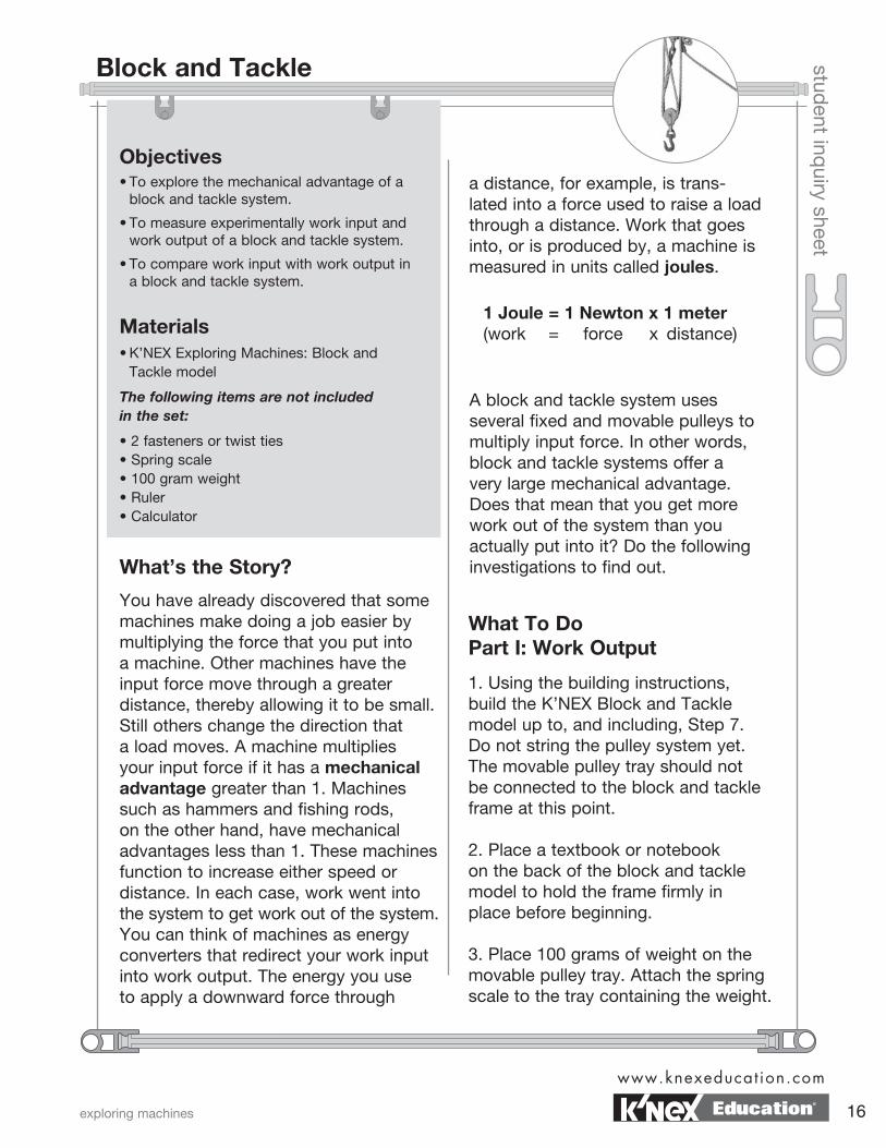
What To Do Part I: Work Output
1. Using the building instructions, build the K’NEX Block and Tackle model up to, and including, Step 7. Do not string the pulley system yet. The movable pulley tray should not be connected to the block and tackle frame at this point.
2. Place a textbook or notebook on the back of the block and tackle model to hold the frame firmly in place before beginning.
3. Place 100 grams of weight on the movable pulley tray. Attach the spring scale to the tray containing the weight.
exploring machines
www.knexeducat ion.com
16
Block and Tackle
Education®
student inq
uiry sheet
Multiply the force of the weighted tray by the distance that the tray moved. Record your calculation in Table 1. This is the amount of work done by the machine (work output).
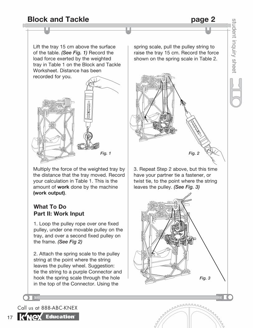
spring scale, pull the pulley string to raise the tray 15 cm. Record the force shown on the spring scale in Table 2.
3. Repeat Step 2 above, but this time have your partner tie a fastener, or twist tie, to the point where the string leaves the pulley. (See Fig. 3)
What To Do Part II: Work Input
1. Loop the pulley rope over one fixed pulley, under one movable pulley on the tray, and over a second fixed pulley on the frame. (See Fig 2)
2. Attach the spring scale to the pulley string at the point where the string leaves the pulley wheel. Suggestion: tie the string to a purple Connector and hook the spring scale through the hole in the top of the Connector. Using the
Fig. 1 Fig. 2
Fig. 3
Call us at 888-ABC-KNEX
17
Block and Tackle page 2
Education®
Lift the tray 15 cm above the surface of the table. (See Fig. 1) Record the load force exerted by the weighted tray in Table 1 on the Block and Tackle Worksheet. Distance has been recorded for you.
student inq
uiry sheet
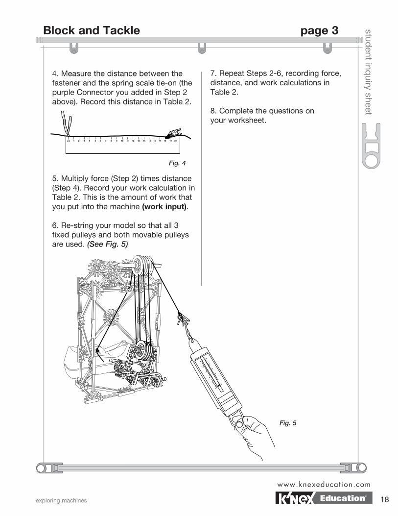
4. Measure the distance between the fastener and the spring scale tie-on (the purple Connector you added in Step 2 above). Record this distance in Table 2.
5. Multiply force (Step 2) times distance (Step 4). Record your work calculation in Table 2. This is the amount of work that you put into the machine (work input).
6. Re-string your model so that all 3 fixed pulleys and both movable pulleys are used. (See Fig. 5)
7. Repeat Steps 2-6, recording force, distance, and work calculations in Table 2.
8. Complete the questions on your worksheet.
Fig. 4
Fig. 5
exploring machines
www.knexeducat ion.com
18
Block and Tackle page 3
Education®
datenamestud
ent worksheet
Think About
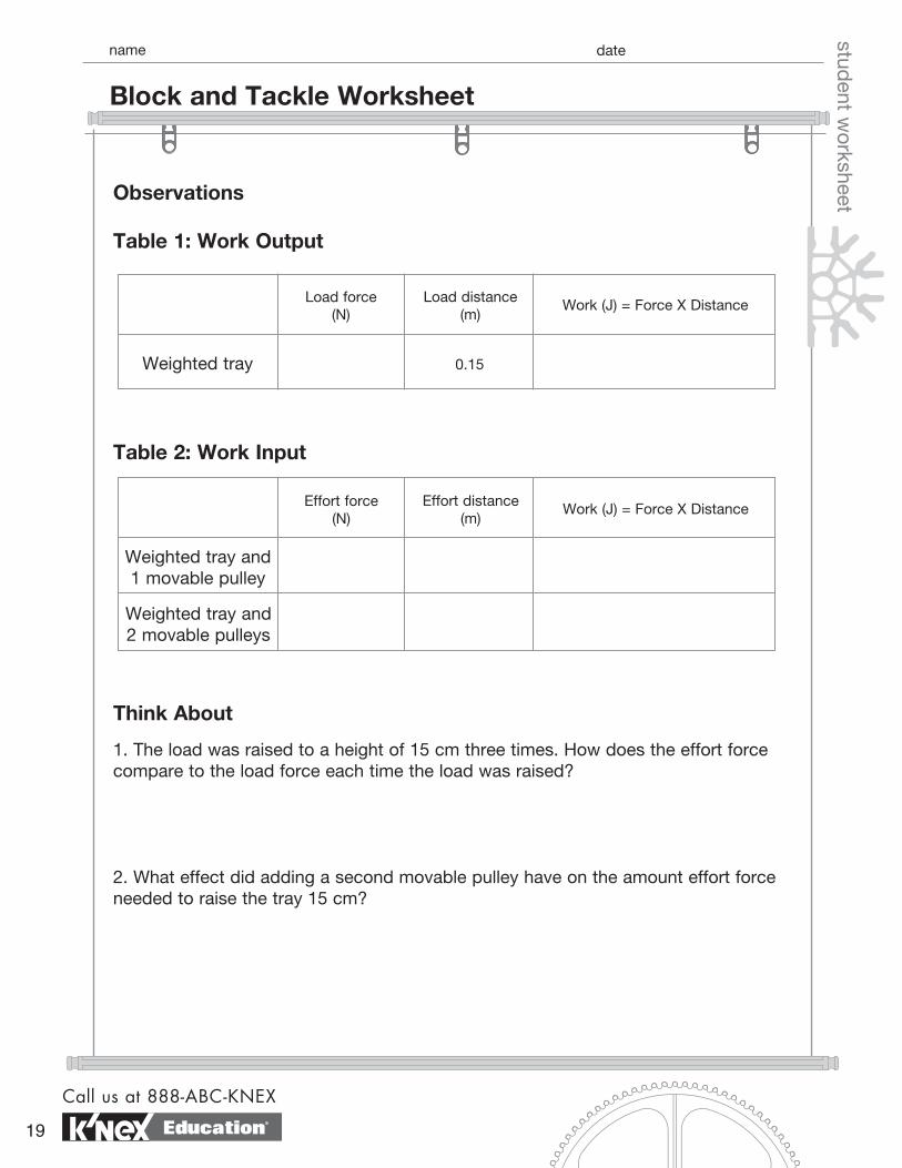
1. The load was raised to a height of 15 cm three times. How does the effort force compare to the load force each time the load was raised?
2. What effect did adding a second movable pulley have on the amount effort force needed to raise the tray 15 cm?
Load force (N)
Table 1: Work Output
Load distance (m)
Weighted tray
Work (J) = Force X Distance
0.15
Effort force (N)
Table 2: Work Input
Effort distance (m)
Weighted tray and 1 movable pulley
Work (J) = Force X Distance
Weighted tray and 2 movable pulleys
Observations
Call us at 888-ABC-KNEX
19
Block and Tackle Worksheet
Education®
ChallengeDraw a block and tackle of your own design. Label the effort force and the load force. Describe the relationship between work input and work output for your block and tackle system.
datenamestud
ent worksheet3. Was there trade-off, (gain versus loss,) for adding a second movable pulley?
If so, what was exchanged for what?
4. How did work input compare with work output when one and two movable pulleys were used?
exploring machines
www.knexeducat ion.com
20
Block and Tackle Worksheet page 2
Education®
student inq
uiry sheet
Objectives• To observe the mechanical advantage of a fixed pulley system.
• To compare a fixed pulley system with a movable pulley system.
Materials• K’NEX Exploring Machines: Elevator model
The following items are not included in the set:
• 2 paper clips (standard size)• Spring scale (5-10 Newtons) • Masking tape or dot stickers
What’s the Story?
If your teacher asks you to raise the flag outside the school, how would you do it? Climb the pole? Use a ladder? Both these methods are difficult and dangerous. The flagpole offers a safer option: a pulley. A pulley is a grooved wheel with a rope or chain that runs around the groove. Pulleys can be either fixed or movable. Fixed pulleys, like those attached to the top of a flagpole, do not move. Movable pulleys are pulleys attached to objects being moved. They move as the object is moved. Both types of pulleys are used to lift heavy loads. Which type of pulley manages this task best? Do the activity below to find out.
What To Do
1. Build the K’NEX Elevator model. Before installing the cars in the elevator, weigh each with the spring scale.
2. On masking tape, or a small sticker, label the car attached to the fixed pulley, “A” and the car attached to the movable pulley system, “B”.
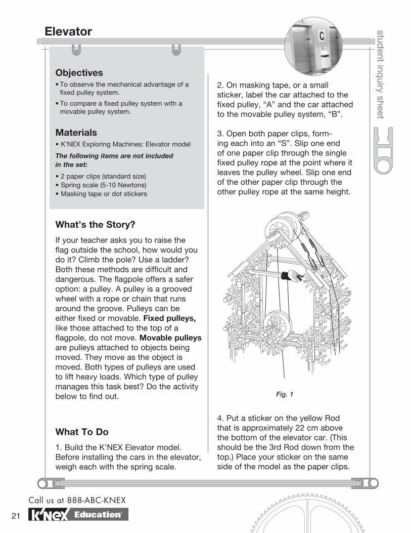
3. Open both paper clips, form-ing each into an “S”. Slip one end of one paper clip through the single fixed pulley rope at the point where it leaves the pulley wheel. Slip one end of the other paper clip through the other pulley rope at the same height.
4. Put a sticker on the yellow Rod that is approximately 22 cm above the bottom of the elevator car. (This should be the 3rd Rod down from the top.) Place your sticker on the same side of the model as the paper clips.
Fig. 1
Call us at 888-ABC-KNEX
21
Elevator
Education®
student inq
uiry sheet
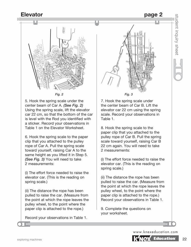
5. Hook the spring scale under the center beam of Car A. (See Fig. 2) Using the spring scale, lift the elevator car 22 cm, so that the bottom of the car is level with the Rod you identified with a sticker. Record your observations in Table 1 on the Elevator Worksheet.
6. Hook the spring scale to the paper clip that you attached to the pulley rope of Car A. Pull the spring scale toward yourself, raising Car A to the same height as you lifted it in Step 5. (See Fig. 3) You will need to take 2 measurements:
(i) The effort force needed to raise the elevator car. (This is the reading on spring scale.)
(ii) The distance the rope has been pulled to raise the car. (Measure from the point at which the rope leaves the pulley wheel, to the point where the paper clip is attached to the rope.)
Record your observations in Table 1.
7. Hook the spring scale under the center beam of Car B. Lift the elevator car 22 cm using the spring scale. Record your observations in Table 1.
8. Hook the spring scale to the paper clip that you attached to the pulley rope of Car B. Pull the spring scale toward yourself, raising Car B 22 cm again. You will need to take 2 measurements:
(i) The effort force needed to raise the elevator car. (This is the reading on spring scale.)
(ii) The distance the rope has been pulled to raise the car. (Measure from the point at which the rope leaves the pulley wheel, to the point where the paper clip is attached to the rope.)Record your observations in Table 1.
9. Complete the questions on your worksheet.
Fig. 2 Fig. 3
exploring machines
www.knexeducat ion.com
22
Elevator page 2
Education®
datenamestud
ent worksheet
Think About
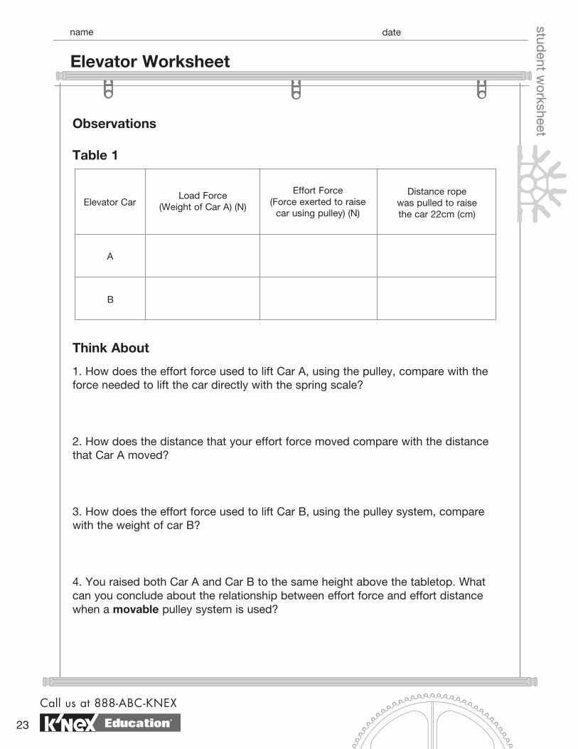
1. How does the effort force used to lift Car A, using the pulley, compare with the force needed to lift the car directly with the spring scale?
2. How does the distance that your effort force moved compare with the distance that Car A moved?
3. How does the effort force used to lift Car B, using the pulley system, compare with the weight of car B?
4. You raised both Car A and Car B to the same height above the tabletop. What can you conclude about the relationship between effort force and effort distance when a movable pulley system is used?
Elevator CarLoad Force
(Weight of Car A) (N)
Effort Force (Force exerted to raise
car using pulley) (N)
Distance rope was pulled to raise the car 22cm (cm)
A
B
Table 1
Observations
Call us at 888-ABC-KNEX
23
Elevator Worksheet
Education®
datenamestud
ent worksheet
ChallengeWhich pulley system is most likely present in a real elevator system? Explain your reasoning.
5. The mechanical advantage of a pulley system can be determined from the effort and load forces, using the formula shown below.
Using your observations and your data, calculate the mechanical advantage of the single fixed pulley and the mechanical advantage of the single movable pulley systems.
load force effort force
MA =
exploring machines
www.knexeducat ion.com
24
Elevator Worksheet page 2
Education®
Screwdriver student inq
uiry sheet
Objectives• To determine experimentally the mechanical advantage of a wheel and axle system.
• To determine mathematically the mechanical advantage of a wheel and axle system.
Materials• K’NEX Exploring Machines: Screwdriver model
The following items are not included in the set:
• Tape • String or twine • 2 – fishing sinkers or other objects to be used as weights • Ruler
What’s the Story?
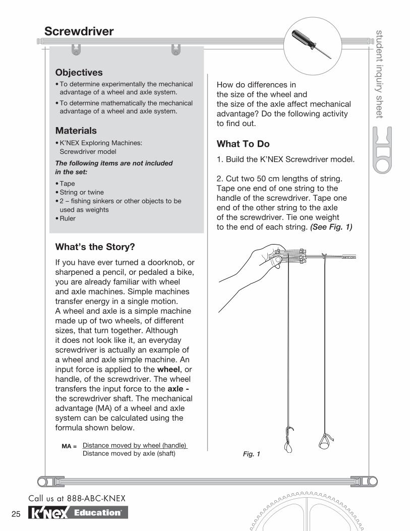
If you have ever turned a doorknob, or sharpened a pencil, or pedaled a bike, you are already familiar with wheel and axle machines. Simple machines transfer energy in a single motion. A wheel and axle is a simple machine made up of two wheels, of different sizes, that turn together. Although it does not look like it, an everyday screwdriver is actually an example of a wheel and axle simple machine. An input force is applied to the wheel, or handle, of the screwdriver. The wheel transfers the input force to the axle - the screwdriver shaft. The mechanical advantage (MA) of a wheel and axle system can be calculated using the formula shown below.
How do differences in the size of the wheel and the size of the axle affect mechanical advantage? Do the following activity to find out.
What To Do
1. Build the K’NEX Screwdriver model.
2. Cut two 50 cm lengths of string. Tape one end of one string to the handle of the screwdriver. Tape one end of the other string to the axle of the screwdriver. Tie one weight to the end of each string. (See Fig. 1)
Distance moved by wheel (handle) Distance moved by axle (shaft)
MA =Fig. 1
Call us at 888-ABC-KNEX
25 Education®
student inq
uiry sheet
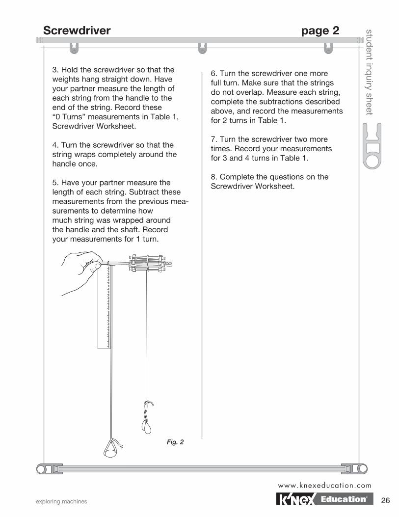
3. Hold the screwdriver so that the weights hang straight down. Have your partner measure the length of each string from the handle to the end of the string. Record these “0 Turns” measurements in Table 1, Screwdriver Worksheet.
4. Turn the screwdriver so that the string wraps completely around the handle once.
5. Have your partner measure the length of each string. Subtract these measurements from the previous mea-surements to determine how much string was wrapped around the handle and the shaft. Record your measurements for 1 turn.
6. Turn the screwdriver one more full turn. Make sure that the strings do not overlap. Measure each string, complete the subtractions described above, and record the measurements for 2 turns in Table 1.
7. Turn the screwdriver two more times. Record your measurements for 3 and 4 turns in Table 1.
8. Complete the questions on the Screwdriver Worksheet.
Fig. 2
exploring machines
www.knexeducat ion.com
26
Screwdriver page 2
Education®
datenamestud
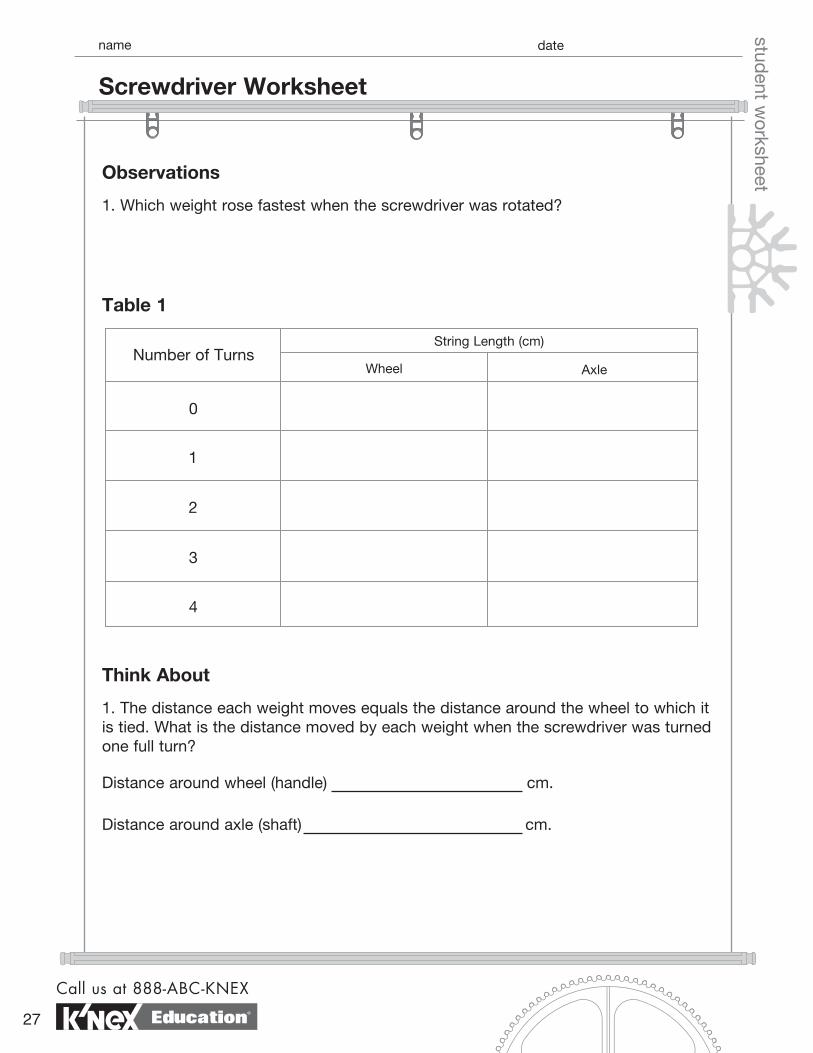
ent worksheetObservations
1. Which weight rose fastest when the screwdriver was rotated?
Think About
1. The distance each weight moves equals the distance around the wheel to which it is tied. What is the distance moved by each weight when the screwdriver was turned one full turn?
Table 1
Distance around wheel (handle) cm.
Distance around axle (shaft) cm.
String Length (cm)
Wheel
1
2
AxleNumber of Turns
0
3
4
Call us at 888-ABC-KNEX
27
Screwdriver Worksheet
Education®
datenamestud
ent worksheet
2. Calculate the mechanical advantage of your screwdriver using the formula shown below.
3. If you inserted a screw into a wall using your K’NEX screwdriver, how many times farther must the handle travel than the shaft?
4. What is gained when using a screwdriver? Use evidence from your investigation to support your answer.
5. Like all other simple machines, there is a trade-off when using a wheel and axle machine. Based on your calculation in Question 2 and your understanding of work, what is the trade-off when using a screwdriver? Remember, Work = Force X Distance.
Distance moved by wheel (handle) Distance moved by axle (shaft)
MA =
exploring machines
www.knexeducat ion.com
28
Screwdriver Worksheet page 2
Education®
datenamestud
ent worksheet
Challenge(a) You calculated the mechanical advantage of your screwdriver in Question 2 and then again in Question 6. Is the mechanical advantage calculated in Question 2 the same as the mechanical advantage calculated in Question 6?
(b) Name three (3) sources of experimental error that could explain your answer to (a).
6. The actual mechanical advantage of your screwdriver can be calculated directly from the machine using the formula shown below.
Measure and calculate the mechanical advantage of your K’NEX screwdriver using the formula shown above. Show all work in the space below.
radius of wheelradius of axle
MA =
Call us at 888-ABC-KNEX
29
Screwdriver Worksheet page 3
Education®
student inq
uiry sheet
Objectives• To observe the effect on mechanical advantage when effort force is applied to the small wheel (axle) of a wheel and axle machine.
Materials• K’NEX Exploring Machines: Paddlewheel Boat model
The following items are not included in the set:
• Meterstick • Masking tape • Spring scale (5-10 Newtons)• Graph Paper
What’s the Story?
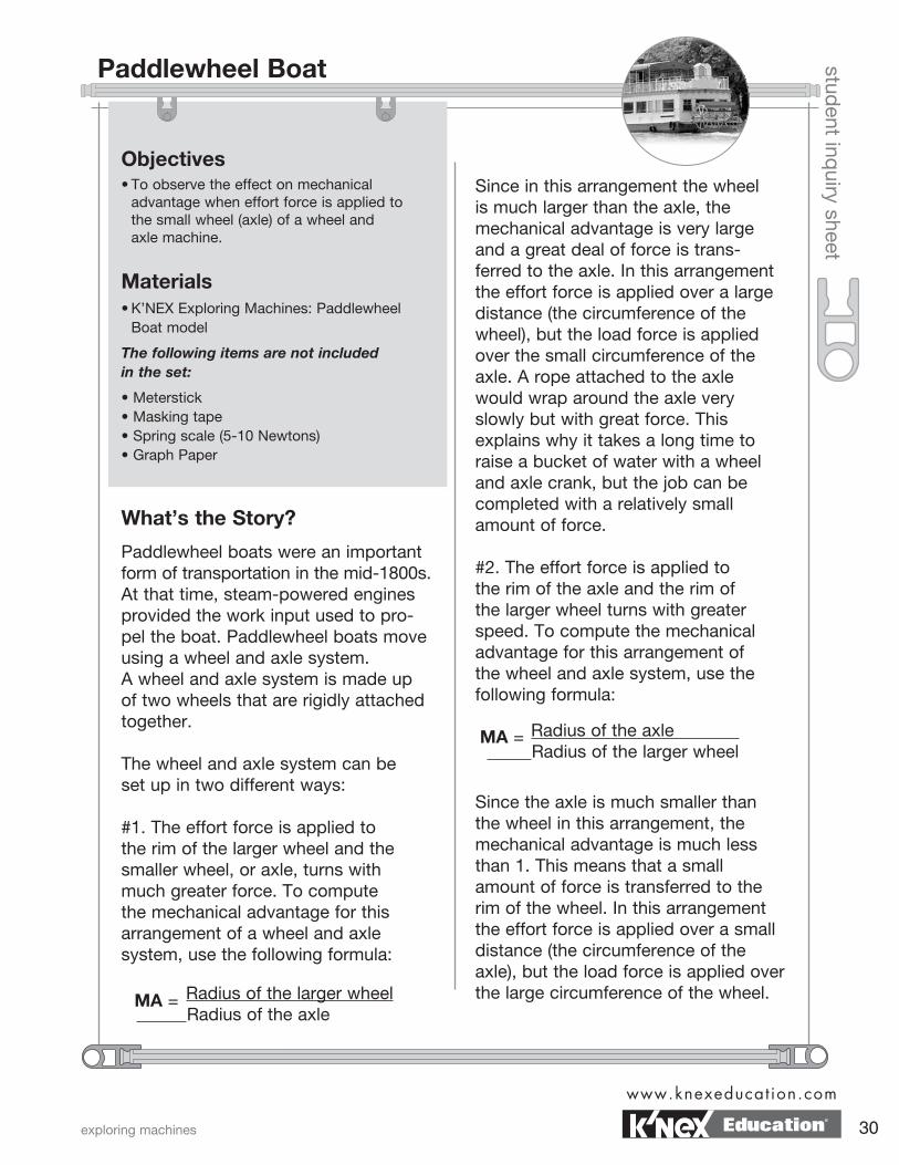
Paddlewheel boats were an important form of transportation in the mid-1800s. At that time, steam-powered engines provided the work input used to pro-pel the boat. Paddlewheel boats move using a wheel and axle system. A wheel and axle system is made up of two wheels that are rigidly attached together.
The wheel and axle system can be set up in two different ways:
#1. The effort force is applied to the rim of the larger wheel and the smaller wheel, or axle, turns with much greater force. To compute the mechanical advantage for this arrangement of a wheel and axle system, use the following formula:
Since in this arrangement the wheel is much larger than the axle, the mechanical advantage is very large and a great deal of force is trans-ferred to the axle. In this arrangement the effort force is applied over a large distance (the circumference of the wheel), but the load force is applied over the small circumference of the axle. A rope attached to the axle would wrap around the axle very slowly but with great force. This explains why it takes a long time to raise a bucket of water with a wheel and axle crank, but the job can be completed with a relatively small amount of force.
#2. The effort force is applied to the rim of the axle and the rim of the larger wheel turns with greater speed. To compute the mechanical advantage for this arrangement of the wheel and axle system, use the following formula:
Radius of the larger wheel Radius of the axle
Since the axle is much smaller than the wheel in this arrangement, the mechanical advantage is much less than 1. This means that a small amount of force is transferred to the rim of the wheel. In this arrangement the effort force is applied over a small distance (the circumference of the axle), but the load force is applied over the large circumference of the wheel.MA =
Radius of the axle Radius of the larger wheel
MA =
exploring machines
www.knexeducat ion.com
30
Paddlewheel Boat
Education®
student inq
uiry sheet
A rope attached to the wheel would wrap around the wheel very quickly but with less force. Much force, for example, must be applied to the axle of your family car so that its wheels turn fast enough and with enough force to move it.
In the paddlewheel boat model, an effort force is applied to a small wheel - the axle. This then turns the paddlewheels. What effect does applying the effort force to the smaller wheel have on the mechanical advantage of the machine? Do the following activity to find out.
Getting Started
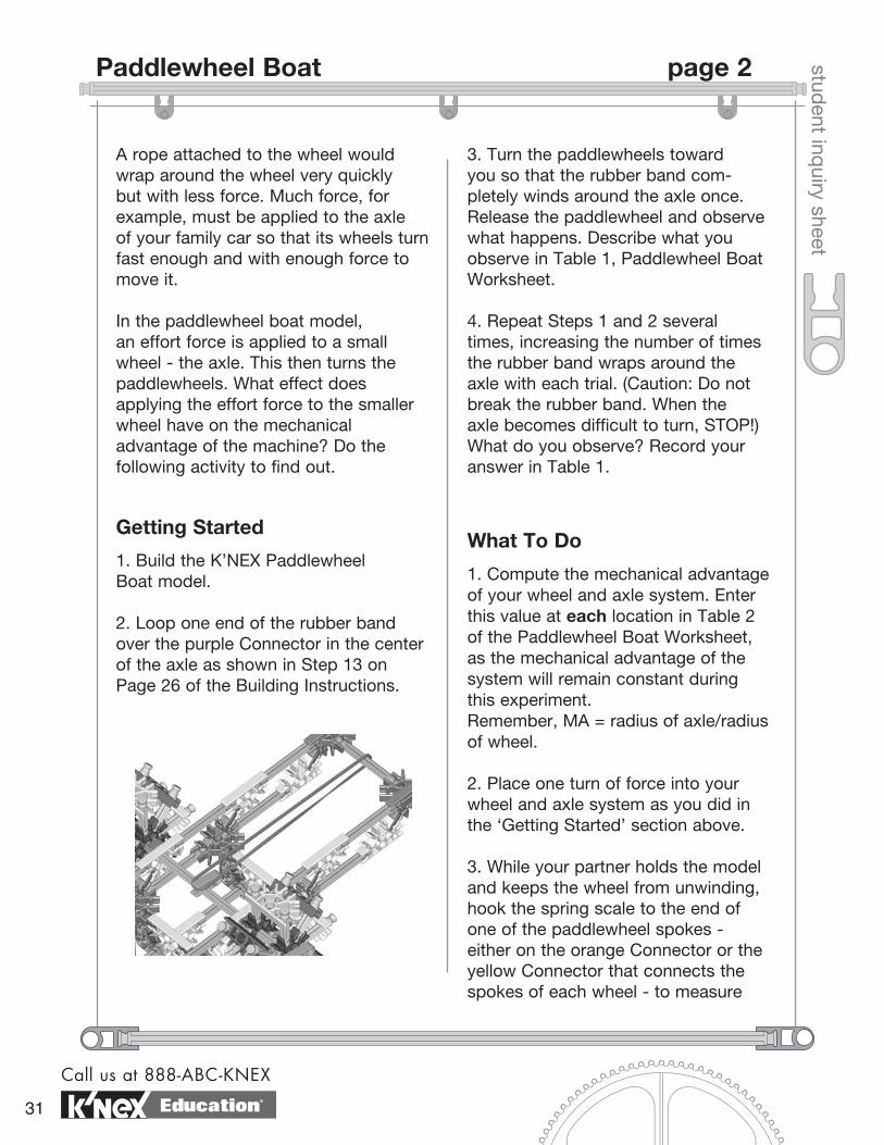
1. Build the K’NEX Paddlewheel Boat model.
2. Loop one end of the rubber band over the purple Connector in the center of the axle as shown in Step 13 on Page 26 of the Building Instructions.
3. Turn the paddlewheels toward you so that the rubber band com-pletely winds around the axle once. Release the paddlewheel and observe what happens. Describe what you observe in Table 1, Paddlewheel Boat Worksheet.
4. Repeat Steps 1 and 2 several times, increasing the number of times the rubber band wraps around the axle with each trial. (Caution: Do not break the rubber band. When the axle becomes difficult to turn, STOP!) What do you observe? Record your answer in Table 1.
What To Do
1. Compute the mechanical advantage of your wheel and axle system. Enter this value at each location in Table 2 of the Paddlewheel Boat Worksheet, as the mechanical advantage of the system will remain constant during this experiment. Remember, MA = radius of axle/radius of wheel.
2. Place one turn of force into your wheel and axle system as you did in the ‘Getting Started’ section above.
3. While your partner holds the model and keeps the wheel from unwinding, hook the spring scale to the end of one of the paddlewheel spokes - either on the orange Connector or the yellow Connector that connects the spokes of each wheel - to measure
Call us at 888-ABC-KNEX
31
Paddlewheel Boat page 2
Education®
student inq
uiry sheet
how much Load Force is being appliedat the edge of the wheel. (NOTE: Be sure that there is one complete turn of the rubber band around the axle.) Record the spring scale reading in Table 2.
4. Repeat Steps 1, 2, & 3 for two, three, and four turns of force on the axle of your system. Continue further trials if your earlier testing indicates that you can put more than four turns of rubber band force into your wheel and axle system.
5. Complete the questions on the Paddlewheel Boat Worksheet.
notes
exploring machines
www.knexeducat ion.com
32
Paddlewheel Boat page 3
Education®
datenamestud
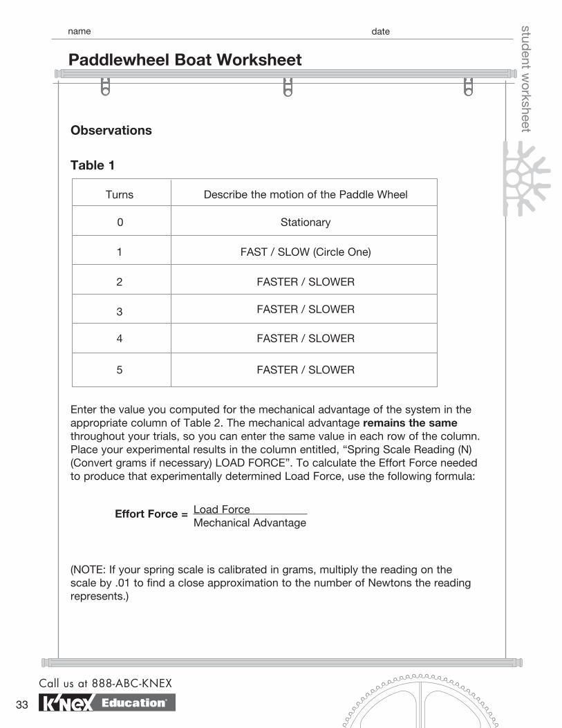
ent worksheetObservations
Table 1
Turns Describe the motion of the Paddle Wheel
0
1
2
3
4
5
Stationary
FAST / SLOW (Circle One)
FASTER / SLOWER
FASTER / SLOWER
FASTER / SLOWER
FASTER / SLOWER
Enter the value you computed for the mechanical advantage of the system in the appropriate column of Table 2. The mechanical advantage remains the same throughout your trials, so you can enter the same value in each row of the column. Place your experimental results in the column entitled, “Spring Scale Reading (N) (Convert grams if necessary) LOAD FORCE”. To calculate the Effort Force needed to produce that experimentally determined Load Force, use the following formula:
Load Force Mechanical Advantage
(NOTE: If your spring scale is calibrated in grams, multiply the reading on the scale by .01 to find a close approximation to the number of Newtons the reading represents.)
Effort Force =
Call us at 888-ABC-KNEX
33
Paddlewheel Boat Worksheet
Education®
datenamestud
ent worksheet
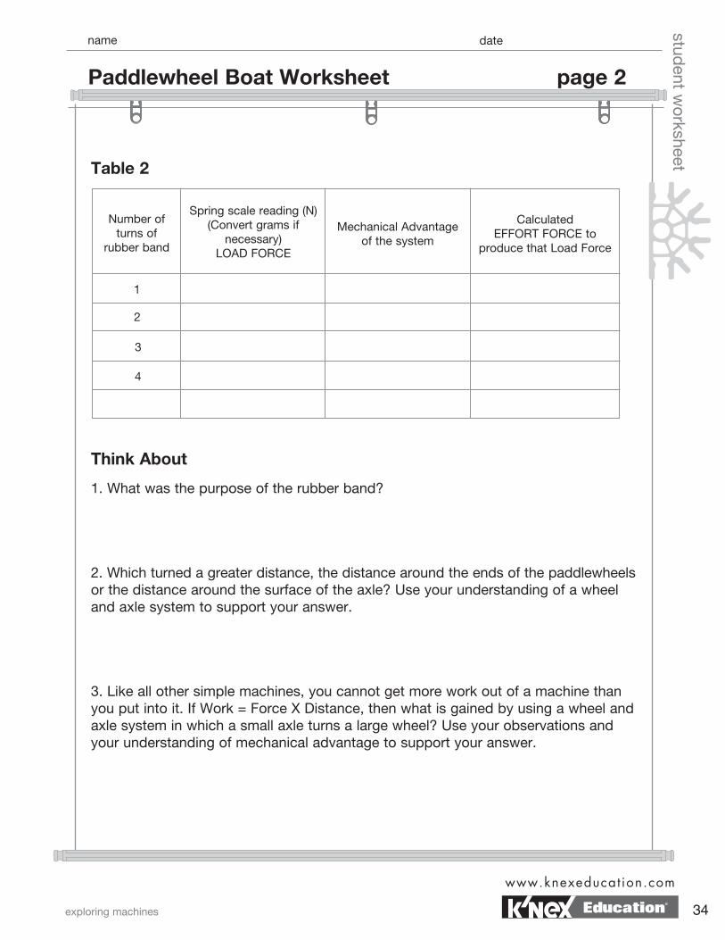
Think About
1. What was the purpose of the rubber band?
2. Which turned a greater distance, the distance around the ends of the paddlewheels or the distance around the surface of the axle? Use your understanding of a wheel and axle system to support your answer.
3. Like all other simple machines, you cannot get more work out of a machine than you put into it. If Work = Force X Distance, then what is gained by using a wheel and axle system in which a small axle turns a large wheel? Use your observations and your understanding of mechanical advantage to support your answer.
Table 2
Number of turns of
rubber band
Spring scale reading (N) (Convert grams if
necessary) LOAD FORCE
Mechanical Advantage of the system
Calculated EFFORT FORCE to
produce that Load Force
1
2
3
4
exploring machines
www.knexeducat ion.com
34
Paddlewheel Boat Worksheet page 2
Education®
datenamestud
ent worksheet
Challenge1. List and describe three design changes that you could make to your boat that would increase the speed or the distance that it travels. If time permits, test your design changes.
2. Using the K’NEX Paddlewheel Boat as a starting point, design a paddleboat that will float and move across the water under paddlewheel power. (Hint: You will have to design a system that will enable your boat to float, in addition to designing a technique that will cause your boat to move under paddlewheel power.)
4. Why was the Effort Force you calculated for each trial of your experiment so much larger than the Load Force that was transferred to the rim of the paddlewheel?
5. Plot the data from Table 2 on graph paper provided by your teacher. Plot Effort Force (Vertical Axis) versus NUMBER of turns of the rubber band. Make sure that you label your axes and include units.
6. What information does your graph provide?
Call us at 888-ABC-KNEX
35
Paddlewheel Boat Worksheet page 3
Education®
student inq
uiry sheet
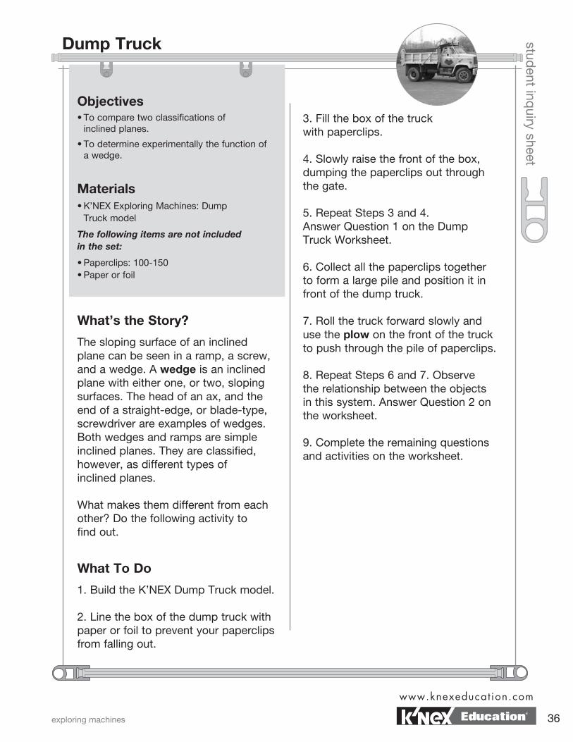
Objectives• To compare two classifications of inclined planes.
• To determine experimentally the function of a wedge.
Materials• K’NEX Exploring Machines: Dump Truck model
The following items are not included in the set:
• Paperclips: 100-150 • Paper or foil
What’s the Story?
The sloping surface of an inclined plane can be seen in a ramp, a screw, and a wedge. A wedge is an inclined plane with either one, or two, sloping surfaces. The head of an ax, and the end of a straight-edge, or blade-type, screwdriver are examples of wedges. Both wedges and ramps are simple inclined planes. They are classified, however, as different types of inclined planes.
What makes them different from each other? Do the following activity to find out.
3. Fill the box of the truck with paperclips.
4. Slowly raise the front of the box, dumping the paperclips out through the gate.
5. Repeat Steps 3 and 4. Answer Question 1 on the Dump Truck Worksheet.
6. Collect all the paperclips together to form a large pile and position it in front of the dump truck.
7. Roll the truck forward slowly and use the plow on the front of the truck to push through the pile of paperclips.
8. Repeat Steps 6 and 7. Observe the relationship between the objects in this system. Answer Question 2 on the worksheet.
9. Complete the remaining questions and activities on the worksheet.
What To Do
1. Build the K’NEX Dump Truck model.
2. Line the box of the dump truck with paper or foil to prevent your paperclips from falling out.
exploring machines
www.knexeducat ion.com
36
Dump Truck
Education®
datenamestud
ent worksheetThink About
1. Raising the box changed the bed of the box into a ramp. How would you describe the motion of the paperclips relative to the box of the dump truck? Which changes position more, the bed of the box or the paperclips?
2. The plow blade acts like a wedge. How would you describe the motion of the paperclips relative to the plow blade? Which changes position more, the plow blade or the paperclips?
3. Why are ramps and wedges classified differently? Use evidence from this activity to explain your reasoning.
4. Your plow blade is an example of an inclined plane that has one sloping surface. Plows used in agriculture often use two or more sloping surfaces. Why is this type of wedge more practical than the one used on your plow?
5. Would your front teeth be classified as ramps or wedges? Explain your answer.
Call us at 888-ABC-KNEX
37
Dump Truck Worksheet
Education®
Inclined Plane student inq
uiry sheet
Objectives• To calculate the mechanical advantage of an
inclined plane.
• To determine experimentally the mechanical advantage of an inclined plane.
• To compare theoretical with actual mechanical advantage.
Materials• K’NEX Exploring Machines: Archimedes’ Screw model
The following items are not included in the set:
• Spring scale (5-10 Newtons)
• Mass or paper cup containing marbles or pennies
What’s the Story?
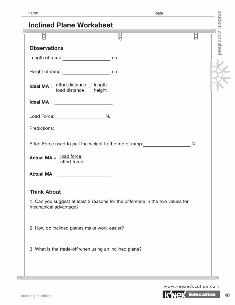
Some simple machines do not look like machines at all. Ramps are sloping surfaces that help you move from one elevation to another. A ramp is an example of an inclined plane. Calculating the mechanical advantage of an inclined plane is similar to calculating the mechanical advantage of a lever. Both calculations involve distances. In the case of inclined planes, the distance the effort moves equals the length of the ramp, from start to finish. The load distance equals the height that the ramp raises the load. In a frictionless system, the ideal mechanical advantage of an inclined plane is calculated using the equation shown below.
However, since friction is present in almost all systems, the actual mechanical advantage of a machine is often less than the ideal mechani-cal advantage. How does an inclined plane make work easier? Do the following activity to find out.
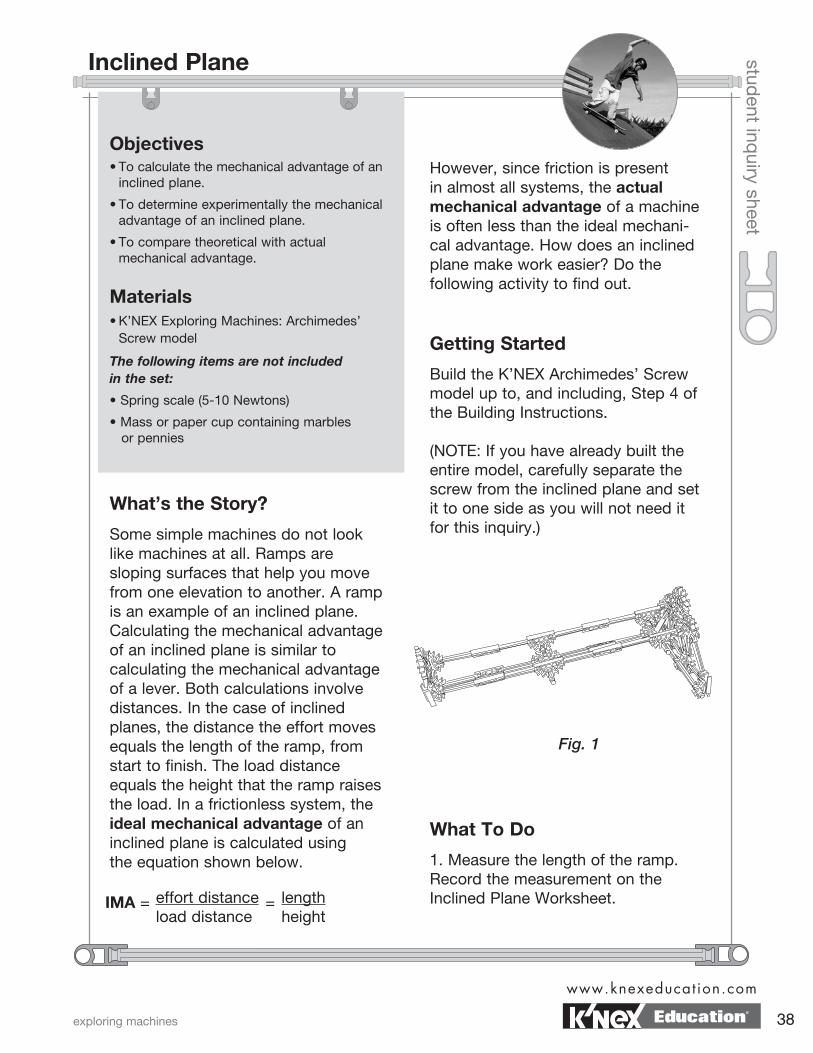
Getting Started
Build the K’NEX Archimedes’ Screw model up to, and including, Step 4 of the Building Instructions.
(NOTE: If you have already built the entire model, carefully separate the screw from the inclined plane and set it to one side as you will not need it for this inquiry.)
What To Do
1. Measure the length of the ramp. Record the measurement on the Inclined Plane Worksheet.
Fig. 1
effort distanceload distance
IMA = lengthheight
=
exploring machines
www.knexeducat ion.com
38Education®
student inq
uiry sheet
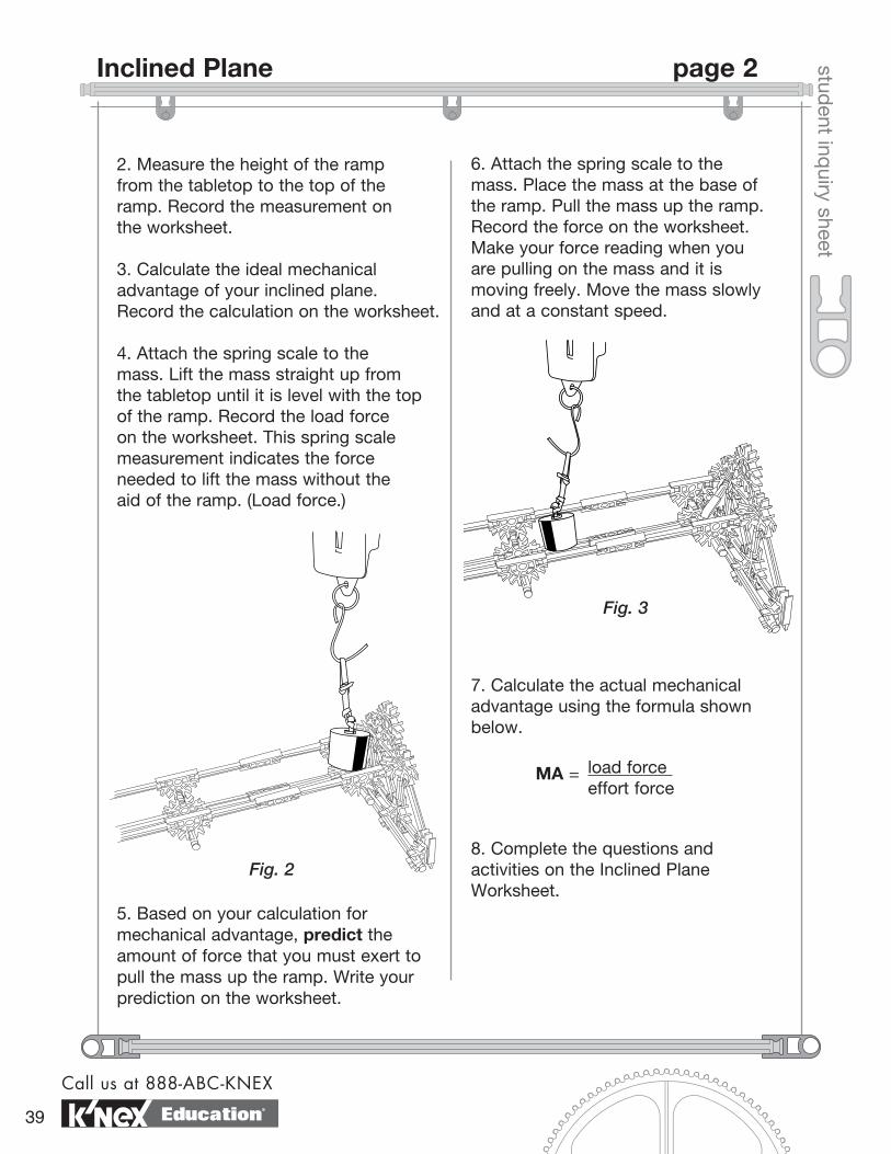
2. Measure the height of the ramp from the tabletop to the top of the ramp. Record the measurement on the worksheet.
3. Calculate the ideal mechanical advantage of your inclined plane. Record the calculation on the worksheet.
4. Attach the spring scale to the mass. Lift the mass straight up from the tabletop until it is level with the top of the ramp. Record the load force on the worksheet. This spring scale measurement indicates the force needed to lift the mass without the aid of the ramp. (Load force.)
5. Based on your calculation for mechanical advantage, predict the amount of force that you must exert to pull the mass up the ramp. Write your prediction on the worksheet.
6. Attach the spring scale to the mass. Place the mass at the base of the ramp. Pull the mass up the ramp. Record the force on the worksheet. Make your force reading when you are pulling on the mass and it is moving freely. Move the mass slowly and at a constant speed.
7. Calculate the actual mechanical advantage using the formula shown below.
8. Complete the questions and activities on the Inclined Plane Worksheet.
load force effort force
MA =
Fig. 2
Fig. 3
Call us at 888-ABC-KNEX
39
Inclined Plane page 2
Education®
Observations
datenamestud
ent worksheet
Think About
1. Can you suggest at least 2 reasons for the difference in the two values for mechanical advantage?
2. How do inclined planes make work easier?
3. What is the trade-off when using an inclined plane?
Length of ramp: cm.
Height of ramp: cm.
Ideal MA =
Load Force: N.
Predictions:
Effort Force used to pull the weight to the top of ramp: N.
Actual MA =
effort distance load distance
Ideal MA = lengthheight
=
load force effort force
Actual MA =
exploring machines
www.knexeducat ion.com
40
Inclined Plane Worksheet
Education®
datenamestud
ent worksheetChallenge
1. How could you change your inclined plane so that its actual mechanical advantage is increased?
2. Test your design. Calculate the actual mechanical advantage of your redesigned plane. Record your observations in the space below.
Call us at 888-ABC-KNEX
41
Inclined Plane Worksheet page 2
Education®
student inq
uiry sheet
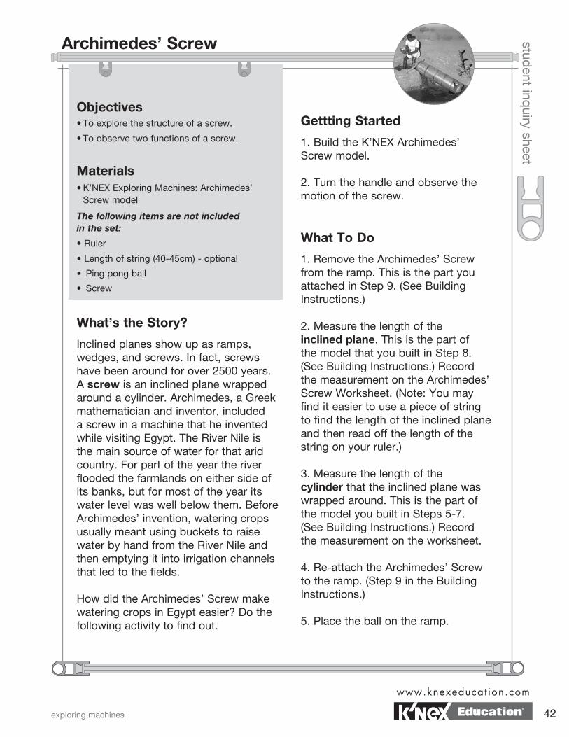
Objectives• To explore the structure of a screw.
• To observe two functions of a screw.
Materials• K’NEX Exploring Machines: Archimedes’ Screw model
The following items are not included in the set:
• Ruler
• Length of string (40-45cm) - optional
• Ping pong ball
• Screw
What’s the Story?
Inclined planes show up as ramps, wedges, and screws. In fact, screws have been around for over 2500 years. A screw is an inclined plane wrapped around a cylinder. Archimedes, a Greek mathematician and inventor, included a screw in a machine that he invented while visiting Egypt. The River Nile is the main source of water for that arid country. For part of the year the river flooded the farmlands on either side of its banks, but for most of the year its water level was well below them. Before Archimedes’ invention, watering crops usually meant using buckets to raise water by hand from the River Nile and then emptying it into irrigation channels that led to the fields.
How did the Archimedes’ Screw make watering crops in Egypt easier? Do the following activity to find out.
Gettting Started
1. Build the K’NEX Archimedes’ Screw model.
2. Turn the handle and observe the motion of the screw.
What To Do
1. Remove the Archimedes’ Screw from the ramp. This is the part you attached in Step 9. (See Building Instructions.)
2. Measure the length of the inclined plane. This is the part of the model that you built in Step 8. (See Building Instructions.) Record the measurement on the Archimedes’ Screw Worksheet. (Note: You may find it easier to use a piece of string to find the length of the inclined plane and then read off the length of the string on your ruler.)
3. Measure the length of the cylinder that the inclined plane was wrapped around. This is the part of the model you built in Steps 5-7. (See Building Instructions.) Record the measurement on the worksheet.
4. Re-attach the Archimedes’ Screw to the ramp. (Step 9 in the Building Instructions.)
5. Place the ball on the ramp.
exploring machines
www.knexeducat ion.com
42
Archimedes’ Screw
Education®
student inq
uiry sheet
6. Turn the handle of the screw. Observe what happens. Record your observation on the worksheet.
7. Complete the questions and activities on the worksheet.
notes
Call us at 888-ABC-KNEX
43
Archimedes’ Screw page 2
Education®
Length of inclined plane: cm.
Observations
Length of cylinder: cm.
datenamestud
ent worksheet
Think About
1. Describe the movement of force through the system.
2. Your Archimedes’ Screw is used to do work. Which variable - force or distance - is multiplied when you use a screw? Explain your reasoning.
3. If you could not turn the machine faster, how could you increase the number of balls moved to the top of the ramp in 1 minute?
4. Using your observations and understanding of screws, describe how an Archimedes’ Screw helped farmers in Egypt to water crops in elevated areas.
5. Can you think of other applications of Archimedes’ type of screw? List them.
6. If you do not already have one, obtain a screw from your teacher. Explore how screws hold objects together. How are an Archimedes’ Screw and a screw used as a fastener different?
What happens when you turn the handle?
exploring machines
www.knexeducat ion.com
44
Archimedes’ Screw Worksheet
Education®
ChallengeThe Archimedes’ Screw is still used in Egypt today. Research Archimedes’ Screw. In the space below, describe ways that you could change your Archimedes’ Screw so that it functions as Archimedes intended. Draw a picture if it helps your descrip-tion.
datenamestud
ent worksheet
Call us at 888-ABC-KNEX
45
Archimedes’ Screw Worksheet page 2
Education®
student inq
uiry sheet
Objectives• To explore the structure of a conveyor belt system.
• To describe and explain the operation of a conveyor belt system.
Materials• K’NEX Exploring Machines: Conveyor Belt model
The following items are not included in the set:
• Dot sticker or masking tape
What’s the Story?
Imagine that your teacher asked you to design a machine that transfers energy and force from one location to another that is approximately 15 meters away. What would your machine look like? What parts would it include? You could use many spur gears meshed together. A sprocket system, however, might be a better option. A sprocket system is made up of two or more gears connected by either a belt or a chain. The gears and chain on a bicycle are an example of a common sprocket and chain system.
How do the parts of a conveyor belt system transfer energy and motion? Do the following activity to find out.
2. Hold the frame of the conveyor belt firmly in place with one hand. Turn the crank of the conveyor belt and observe the direction of motion of each gear.
What To Do
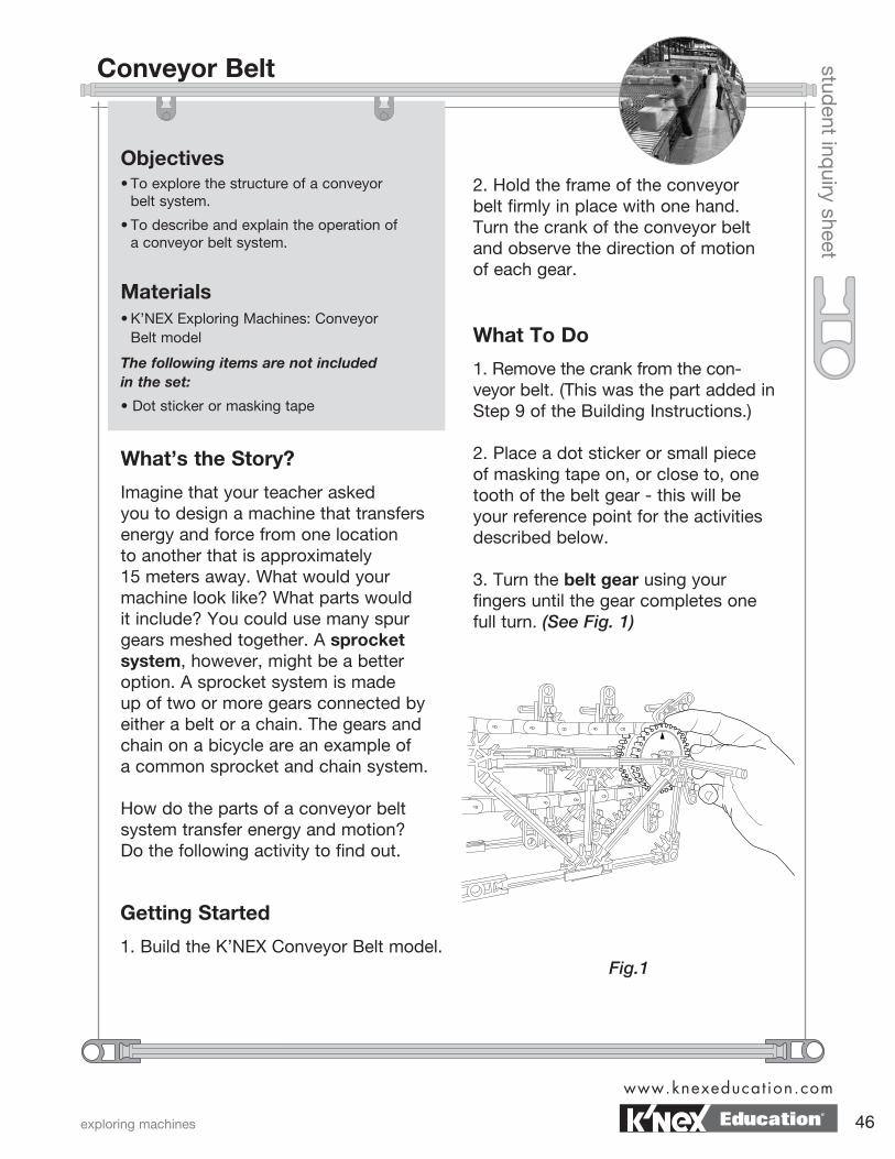
1. Remove the crank from the con-veyor belt. (This was the part added in Step 9 of the Building Instructions.) 2. Place a dot sticker or small piece of masking tape on, or close to, one tooth of the belt gear - this will be your reference point for the activities described below.
3. Turn the belt gear using your fingers until the gear completes one full turn. (See Fig. 1)
Getting Started
1. Build the K’NEX Conveyor Belt model.Fig.1
exploring machines
www.knexeducat ion.com
46
Conveyor Belt
Education®
student inq
uiry sheet
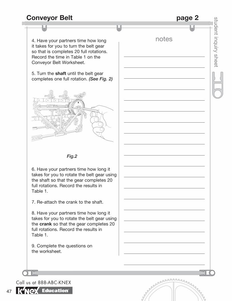
4. Have your partners time how long it takes for you to turn the belt gear so that is completes 20 full rotations. Record the time in Table 1 on the Conveyor Belt Worksheet. 5. Turn the shaft until the belt gear completes one full rotation. (See Fig. 2)
6. Have your partners time how long it takes for you to rotate the belt gear using the shaft so that the gear completes 20 full rotations. Record the results in Table 1.
7. Re-attach the crank to the shaft.
8. Have your partners time how long it takes for you to rotate the belt gear using the crank so that the gear completes 20 full rotations. Record the results in Table 1.
9. Complete the questions on the worksheet.
Fig.2
notes
Call us at 888-ABC-KNEX
47
Conveyor Belt page 2
Education®
datenamestud
ent worksheet
Think About
1. Describe how force is transferred through the system.
2. You used three methods for turning the belt gear. Which method required the most Effort Force? How do you know?
3. How does the weight of the belt affect the amount of force needed to turn the crank?
4. Describe how the moving parts in your conveyor move as you turn the handle. Pay particular attention to the direction in which each part moves.
5. How is it possible for items on a conveyor belt to move in a straight line from place to place if all the parts move in a circular path?
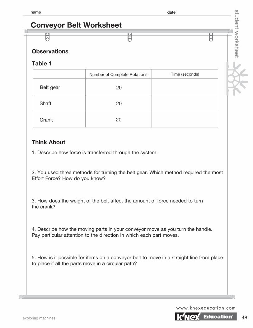
Table 1
Observations
Number of Complete Rotations Time (seconds)
Belt gear
Shaft
Crank
20
20
20
exploring machines
www.knexeducat ion.com
48
Conveyor Belt Worksheet
Education®
datenamestud
ent worksheet
Challenge1. A conveyor belt is a machine that changes the rotational motion of a wheel and axle into straight-line or linear motion. Predict how changing the size of the belt gear would affect the speed of the conveyor belt compared to the speed of the handle as it is turned.
6. Can you determine the mechanical advantage of the conveyor belt system? (Do not include any MA obtained from the handle.)
7. In your own words, describe why you think conveyor belts and chain drive systems are useful?
8. Large airports often use conveyor walkways to transport people over long, straight distances. Why are the conveyor walkways only found in straight sections and are not used to move passengers throughout the entire airport?
Call us at 888-ABC-KNEX
49
Conveyor Belt Worksheet page 2
Education®
Challenge2. Design and draw a conveyor belt system that will improve service at a restaurant. The system must be able to deliver hot foods to the servers’ station and return dirty dishes to the kitchen. If you plan carefully, you should be able to complete this challenge using a single conveyor belt system.
datenamestud
ent worksheet
Challenge3. Using smaller gears provided by your teacher, change the size of the belt gears. Record your observations in the space below.
Challenge4. Why don’t typical conveyor belts have different size gears? Build one to reinforce your answer.
exploring machines
www.knexeducat ion.com
50
Conveyor Belt Worksheet page 3
Education®
student inq
uiry sheet
Objectives• To determine experimentally the mechanical advantage of a rack and pinion gear system.
• To describe and explain the operation of a rack and pinion gear system.
Materials• K’NEX Exploring Machines: Rack and Pinion model
The following items are not included in the set:
• Washable marker
• Dot stickers/masking tape
• Ruler
What’s the Story?
A gear is a wheel that has teeth or cogs along its circumference. Many types of gear systems combine two or more gears, either meshed together directly, or connected by a chain. In a rack and pinion system, a single gear called a pinion meshes with a toothed bar called a rack. Gear systems offer a mechanical advantage when either force or speed is gained. What advantage does a rack and pinion system provide? Complete the following activity to find out.
Getting Started
1. Build the K’NEX Rack and Pinion model.
2. While holding the frame firmly in place, rotate the handle of the rack and pinion. Observe what happens.
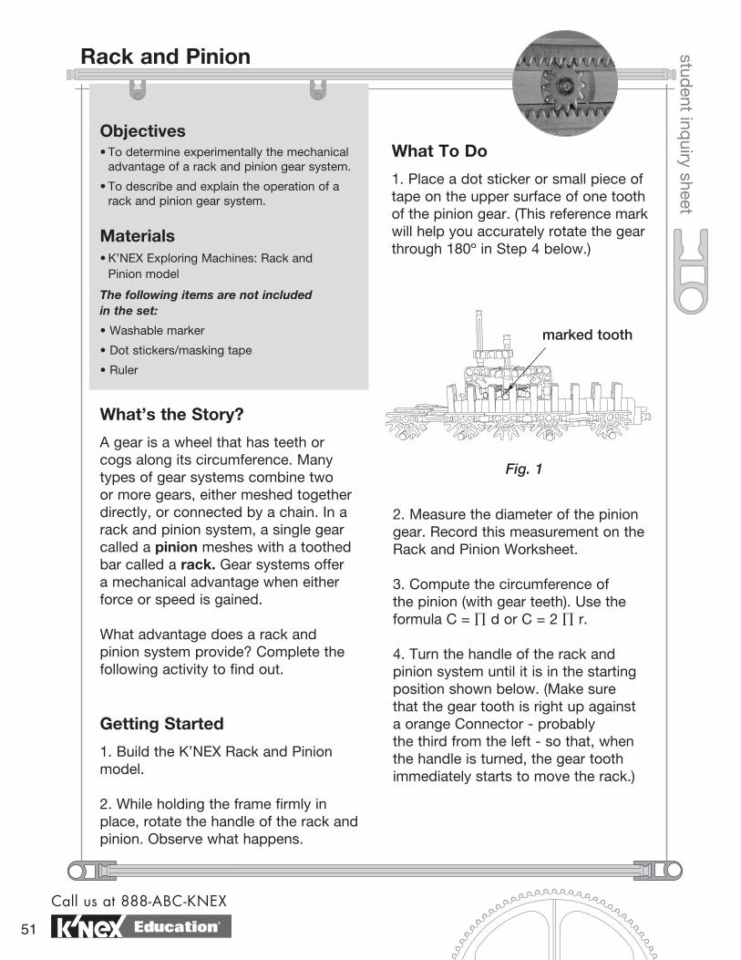
2. Measure the diameter of the pinion gear. Record this measurement on the Rack and Pinion Worksheet.
3. Compute the circumference of the pinion (with gear teeth). Use the formula C = ∏ d or C = 2 ∏ r.
4. Turn the handle of the rack and pinion system until it is in the starting position shown below. (Make sure that the gear tooth is right up against a orange Connector - probably the third from the left - so that, when the handle is turned, the gear tooth immediately starts to move the rack.)
What To Do
1. Place a dot sticker or small piece of tape on the upper surface of one tooth of the pinion gear. (This reference mark will help you accurately rotate the gear through 180º in Step 4 below.)
Fig. 1
marked tooth
Call us at 888-ABC-KNEX
51
Rack and Pinion
Education®
student inq
uiry sheet
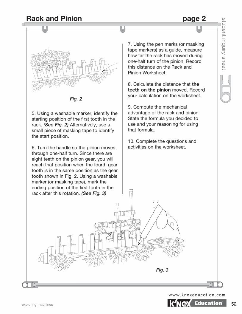
5. Using a washable marker, identify the starting position of the first tooth in the rack. (See Fig. 2) Alternatively, use a small piece of masking tape to identify the start position.
6. Turn the handle so the pinion moves through one-half turn. Since there are eight teeth on the pinion gear, you will reach that position when the fourth gear tooth is in the same position as the gear tooth shown in Fig. 2. Using a washable marker (or masking tape), mark the ending position of the first tooth in the rack after this rotation. (See Fig. 3)
7. Using the pen marks (or masking tape markers) as a guide, measure how far the rack has moved during one-half turn of the pinion. Record this distance on the Rack and Pinion Worksheet.
8. Calculate the distance that the teeth on the pinion moved. Record your calculation on the worksheet.
9. Compute the mechanical advantage of the rack and pinion. State the formula you decided to use and your reasoning for using that formula.
10. Complete the questions and activities on the worksheet.
Fig. 2
Fig. 3
exploring machines
www.knexeducat ion.com
52
Rack and Pinion page 2
Education®
datenamestud
ent worksheet
Think About
1. Compare the distance the rack moved with the distance the teeth on the pinion moved. Write your answer in the space below.
2. Compute an actual mechanical advantage for the rack and pinion gear system. Why did you choose the method you did?
3. How does the motion of the rack compare with the motion of the pinion? (Hint: Think geometry.)
4. List all the steps of force transfer in the system.
5. How is a rack and pinion system useful?
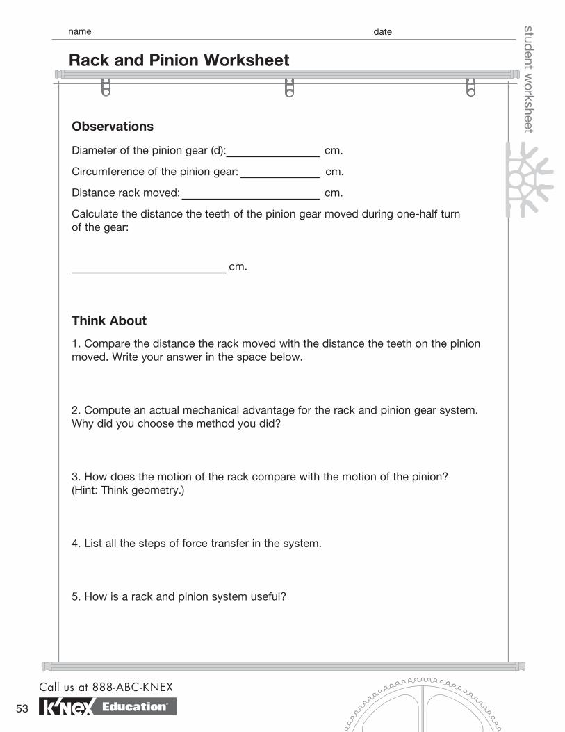
Diameter of the pinion gear (d): cm.
Circumference of the pinion gear: cm.
Distance rack moved: cm.
Calculate the distance the teeth of the pinion gear moved during one-half turn of the gear:
cm.
Observations
Call us at 888-ABC-KNEX
53
Rack and Pinion Worksheet
Education®
datenamestud
ent worksheetChallenge
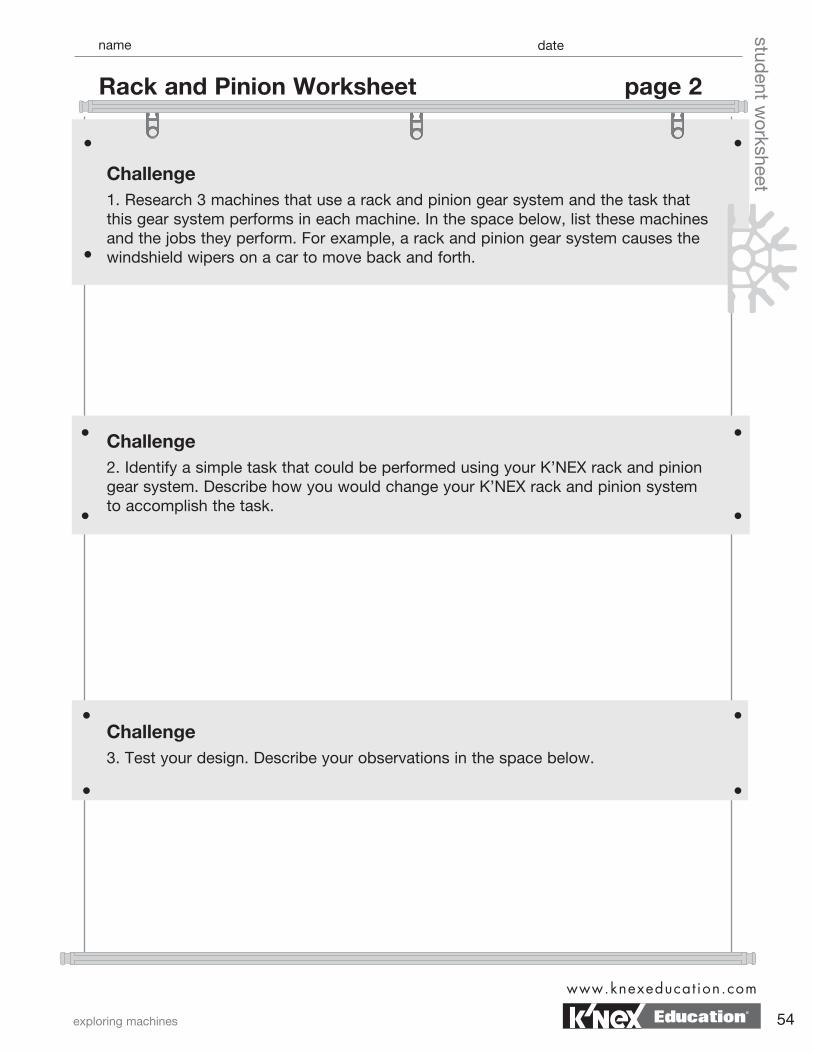
1. Research 3 machines that use a rack and pinion gear system and the task that this gear system performs in each machine. In the space below, list these machines and the jobs they perform. For example, a rack and pinion gear system causes the windshield wipers on a car to move back and forth.
Challenge2. Identify a simple task that could be performed using your K’NEX rack and pinion gear system. Describe how you would change your K’NEX rack and pinion system to accomplish the task.
Challenge3. Test your design. Describe your observations in the space below.
exploring machines
www.knexeducat ion.com
54
Rack and Pinion Worksheet page 2
Education®
student inq
uiry sheet
Objectives• To determine experimentally the gear ratio
of a model crank fan.
• To determine mathematically the gear ratio of a model crank fan.
Materials• K’NEX Exploring Machines: Crank Fan model
• Dot sticker or masking tape (not included in the set)
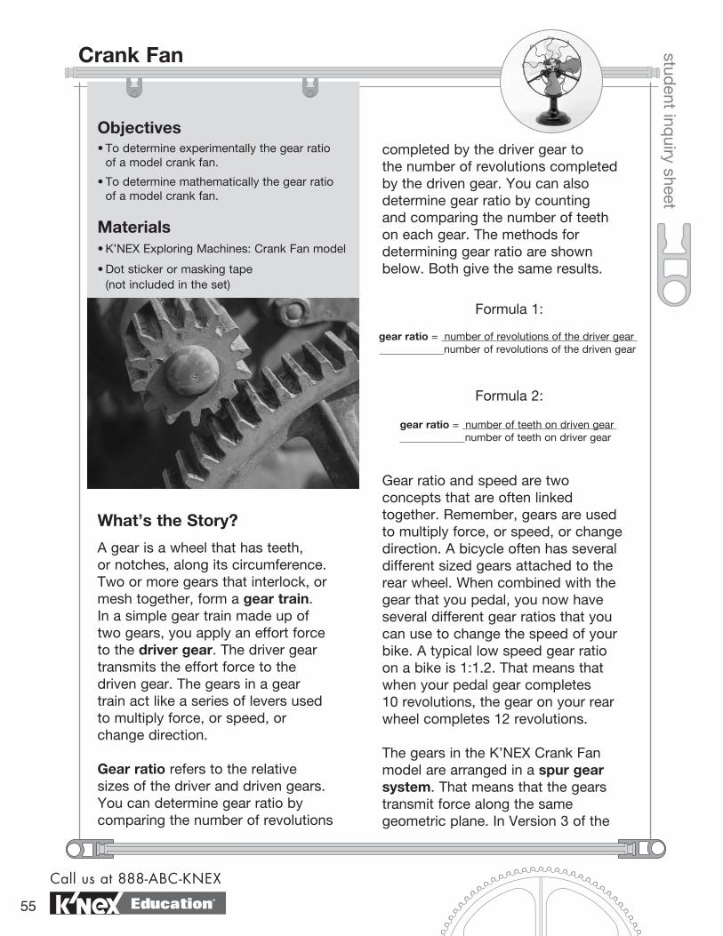
What’s the Story?
A gear is a wheel that has teeth, or notches, along its circumference. Two or more gears that interlock, or mesh together, form a gear train. In a simple gear train made up of two gears, you apply an effort force to the driver gear. The driver gear transmits the effort force to the driven gear. The gears in a gear train act like a series of levers used to multiply force, or speed, or change direction.
Gear ratio refers to the relative sizes of the driver and driven gears. You can determine gear ratio by comparing the number of revolutions
completed by the driver gear to the number of revolutions completed by the driven gear. You can also determine gear ratio by counting and comparing the number of teeth on each gear. The methods for determining gear ratio are shown below. Both give the same results.
gear ratio = number of teeth on driven gear number of teeth on driver gear
gear ratio = number of revolutions of the driver gear number of revolutions of the driven gear
Formula 1:
Formula 2:
Gear ratio and speed are two concepts that are often linked together. Remember, gears are used to multiply force, or speed, or change direction. A bicycle often has several different sized gears attached to the rear wheel. When combined with the gear that you pedal, you now have several different gear ratios that you can use to change the speed of your bike. A typical low speed gear ratio on a bike is 1:1.2. That means that when your pedal gear completes 10 revolutions, the gear on your rear wheel completes 12 revolutions.
The gears in the K’NEX Crank Fan model are arranged in a spur gear system. That means that the gears transmit force along the same geometric plane. In Version 3 of the
Call us at 888-ABC-KNEX
55
Crank Fan
Education®
student inq
uiry sheet
model, a large gear, attached to a crank, meshes with a smaller gear directly above it. The large gear is the driver gear that transmits force to the smaller gear above it.
What is the relationship between gear ratio and speed? Complete the following activity to find out.
Getting Started
1. Build Version 3 of the Crank Fan model. 2. While holding the frame of the crank fan firmly with one hand, spin the fan blades of the crank fan. Spin the blades quickly, while applying force only to the fan blades.
3. While holding the frame of the crank fan firmly with one hand, turn the handle of the crank and observe the speed of the fan.
4. Turn the fan blades and the crank in opposite directions from those in Steps 2 and 3.
What To Do
1. Predict how many times the fan will revolve before the large gear completes one full revolution? Write your prediction on your Crank Fan Worksheet.
2. Arrange the model so that the orangeConnectors of the crank and one of the fan blades are in a vertical position, at right angles to the tabletop.
3. Place a dot sticker or piece of masking tape on the vertical fan blade. Use this as your starting point for the following activities.
4. Slowly turn the crank until the “marked” fan blade completes one full revolution. Observe the position of the crank.
5. Continue to slowly turn the crank, counting the number of revolutions completed by the “marked” fan blade, until the crank returns to the start position. Record the number of revolutions completed by both the driver gear and the fan blade on the Crank Fan Worksheet.
6. Using Formula 1 and your data for complete revolutions, determine the gear ratio for the crank fan. Record your answer on the worksheet.
7. Count the number of teeth on the large driver gear. Record this number on the worksheet.
8. Count the number of teeth on the small driven gear. Record this number on the worksheet.
9. Using Formula 2 and your data for gear teeth count, determine the gear ratio for the crank fan. Record your answer on the worksheet. 10. Complete the questions on the worksheet.
exploring machines
www.knexeducat ion.com
56
Crank Fan page 2
Education®
datenamestud
ent worksheet
How many times will the fan revolve before the large gear completes one full revolution? Write your prediction in the space below.
Observations
Think About
1. How does the gear ratio calculated using Formula 1 compare with the gear ratio calculated using Formula 2?
2. Version 3 of the Crank Fan represents a gear system that has a high gear ratio. That means that there is a large difference between the size of the driver gear and the size of the driven gear. How would you describe the speed of the crank relative to the speed that the fan is moving in this high gear system?
Number of revolutions completed by the driver gear:
Number of revolutions completed by the driven gear attached to the fan:
Gear ratio:
Number of teeth on the driver gear:
Number of teeth on the driven gear:
Gear ratio:
Prediction
Call us at 888-ABC-KNEX
57
Crank Fan Worksheet
Education®
datenamestud
ent worksheet
Challenge1. What would happen if the small gear was used as the driver gear and the large gear was the driven gear? Write your prediction in the space below.
3. Examine the diagram for Version 1 in your Crank Fan Building Instructions. What gear ratio is used in this version of fan construction? Explain the reason behind your answer.
4. Compare the direction in which the fan revolved with the direction in which the driver gear revolved. Explain what caused the direction of motions that you observed. NOTE: Avoid using the terms “clockwise” and “counterclockwise” to describe the motion of the fan because observers on opposite sides of the fan, using these terms, will describe the motion differently.
exploring machines
www.knexeducat ion.com
58
Crank Fan Worksheet page 2
Education®
Challenge2. Using the Crank Fan Building Instructions, build Version 2 of the crank fan model.Turn the crank. Based on your observations and your data, write a conclusion that answers the question, “What is the relationship between gear ratio and speed?”
datenamestud
ent worksheet
Call us at 888-ABC-KNEX
59
Crank Fan Worksheet page 3
Education®
student inq
uiry sheet
Objectives• To determine the mechanical advantage of a
crown gear system.
• To identify simple machines used to transfer input force.
Materials• K’NEX Exploring Machines: Carousel model
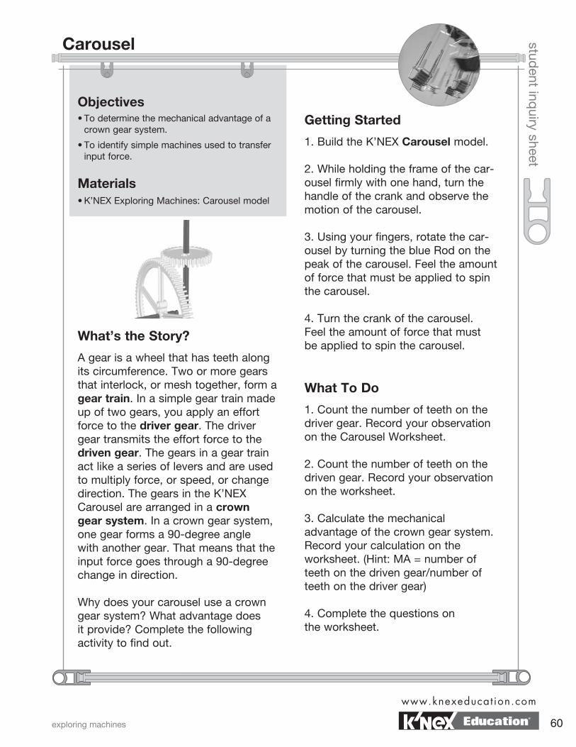
What’s the Story?
A gear is a wheel that has teeth along its circumference. Two or more gears that interlock, or mesh together, form a gear train. In a simple gear train made up of two gears, you apply an effort force to the driver gear. The driver gear transmits the effort force to the driven gear. The gears in a gear train act like a series of levers and are used to multiply force, or speed, or change direction. The gears in the K’NEX Carousel are arranged in a crown gear system. In a crown gear system, one gear forms a 90-degree angle with another gear. That means that the input force goes through a 90-degree change in direction.
Why does your carousel use a crown gear system? What advantage does it provide? Complete the following activity to find out.
Getting Started
1. Build the K’NEX Carousel model.
2. While holding the frame of the car-ousel firmly with one hand, turn the handle of the crank and observe the motion of the carousel.
3. Using your fingers, rotate the car-ousel by turning the blue Rod on the peak of the carousel. Feel the amount of force that must be applied to spin the carousel.
4. Turn the crank of the carousel. Feel the amount of force that must be applied to spin the carousel.
What To Do
1. Count the number of teeth on the driver gear. Record your observation on the Carousel Worksheet.
2. Count the number of teeth on the driven gear. Record your observation on the worksheet.
3. Calculate the mechanical advantage of the crown gear system. Record your calculation on the worksheet. (Hint: MA = number of teeth on the driven gear/number of teeth on the driver gear)
4. Complete the questions on the worksheet.
exploring machines
www.knexeducat ion.com
60
Carousel
Education®
datenamestud
ent worksheet
Number of teeth on driver gear:
Number of teeth on the driven gear:
MA:
Think About
1. How did the crown gear system make work easier? Use evidence from your observations and your data to support your answer.
2. What is/are the trade-off(s) using this system?
3. List two simple machines that combine to form the mechanism used to move the carousel.
(i)
(ii)
4. Draw a carousel design that shows what the carousel would look like if it used a spur gear system. (Feel free to draw a top view or a side view of the carousel.)
Observations
Call us at 888-ABC-KNEX
61
Carousel Worksheet
Education®
datenamestud
ent worksheet
ChallengeResearch and describe another machine that uses a crown gear system.
5. What is the advantage of using a crown gear system?
exploring machines
www.knexeducat ion.com
62
Carousel Worksheet page 2
Education®
student inq
uiry sheet
Objectives• To calculate gear ratios in a two speed transmission system.
• To determine experimentally how changing gear ratio affects torque.
Materials• K’NEX Exploring Machines: Transmission model
• Page 51 of the Building Instructions
The following items are not included in the set:
• String (20-30 cm)
• Weights (10 or 20 gram)
What’s the Story?
Recall that gear ratio can be determined using either the ratio of revolutions or the ratio of teeth on two gears.
you now have several different gear ratios that you can use to change the speed of your bike. A typical low speed gear ratio on a bike is 1:1.2. That means that when the gear attached to your pedal completes 10 revolutions, the gear on your rear wheel, the driven gear, completes 12 revolutions. If it takes 1 minute for the driver gear to complete 10 revolutions, then the driver gear is turning at a rate of 10 revolutions per minute (rpm). As a result of gear ratio and the rate that the driver gear turns, the driven gear turns at a rate of 12 rpm.
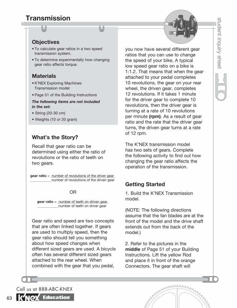
The K’NEX transmission model has two sets of gears. Complete the following activity to find out how changing the gear ratio affects the operation of the transmission.
Getting Started
1. Build the K’NEX Transmission model.
(NOTE: The following directions assume that the fan blades are at the front of the model and the drive shaft extends out from the back of the model.)
2. Refer to the pictures in the middle of Page 51 of your Building Instructions. Lift the yellow Rod and place it in front of the orange Connectors. The gear shaft will
gear ratio = number of teeth on driven gear number of teeth on driver gear
gear ratio = number of revolutions of the driver gear number of revolutions of the driven gear
OR
Gear ratio and speed are two concepts that are often linked together. If gears are used to multiply speed, then the gear ratio should tell you something about how speed changes when different sized gears are used. A bicycle often has several different sized gears attached to the rear wheel. When combined with the gear that you pedal,
Call us at 888-ABC-KNEX
63
Transmission
Education®
student inq
uiry sheet
move all the way forward. Turn the drive shaft and observe what happens. Feel how much effort force is needed to turn the drive shaft. This is first gear.
3. Refer to the pictures at the bottom of Page 51 of your Building Instructions. Lift the yellow Rod and place it behind the orange Connectors. The gear shaft will move all the way to the rear of the transmission. Turn the drive shaft and observe what happens. Again, feel how much effort is needed to turn the drive shaft. This is second gear.
What To Do
1. Return the transmission model to first gear.
2. On the Transmission Worksheet, identify the data source that you will use to gather the information needed to calculate the gear ratio for your transmission.
3. On the Transmission Worksheet, identify the equation that you will use to calculate the gear ratio.
4. Calculate the gear ratio of the transmission when it is in first gear. Record the calculation in Table 1.
5. With the transmission in first gear, turn the drive shaft. Record your observations in Table 1.
6. Shift the transmission to second gear.
7. Calculate the gear ratio of the transmission when it is in second gear. Record the calculation in Table 1.
8. With the transmission in second gear, turn the drive shaft. Record your observations in Table 1.
9. Complete the questions and activities on the worksheet.
exploring machines
www.knexeducat ion.com
64
Transmission page 2
Education®
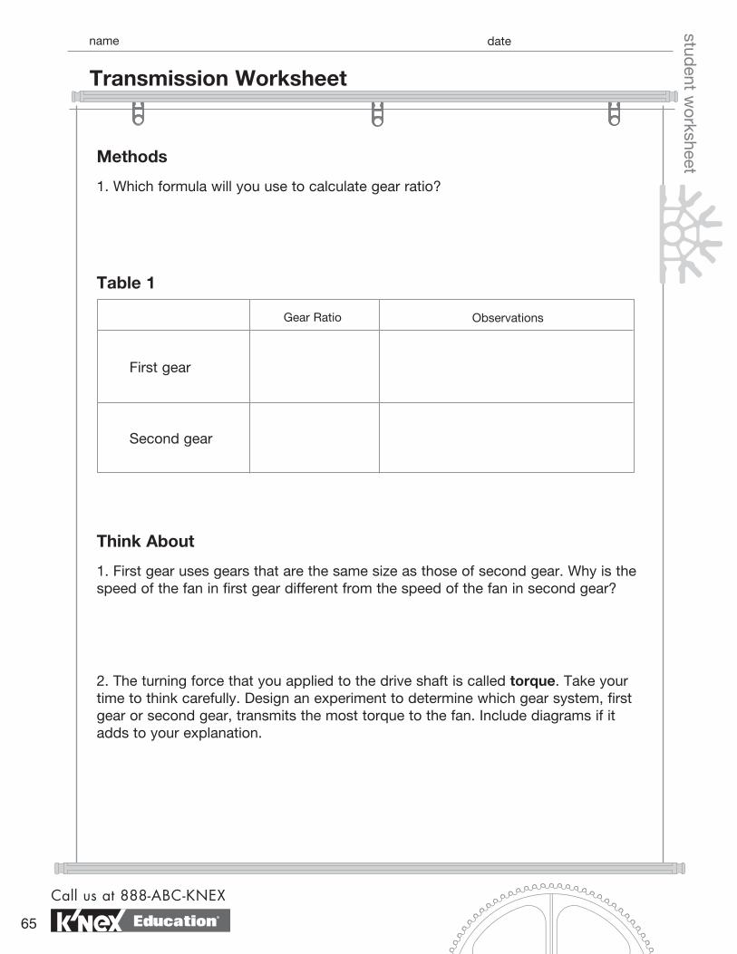
datenamestud
ent worksheetMethods
1. Which formula will you use to calculate gear ratio?
Think About
1. First gear uses gears that are the same size as those of second gear. Why is the speed of the fan in first gear different from the speed of the fan in second gear?
2. The turning force that you applied to the drive shaft is called torque. Take your time to think carefully. Design an experiment to determine which gear system, first gear or second gear, transmits the most torque to the fan. Include diagrams if it adds to your explanation.
Gear Ratio
Table 1
Observations
First gear
Second gear
Call us at 888-ABC-KNEX
65
Transmission Worksheet
Education®
datenamestud
ent worksheet3. Based on your experiment, which gear transmits the most turning force (torque)
to the fan?
4. What is the relationship between gear ratio, speed, and torque? Explain your reasoning.
exploring machines
www.knexeducat ion.com
66
Transmission Worksheet page 2
Education®
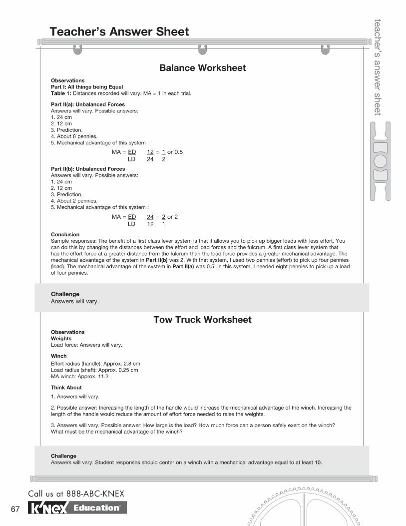
Balance Worksheet
teacher’s answer sheet
Tow Truck Worksheet
Observations Part I: All things being EqualTable 1: Distances recorded will vary. MA = 1 in each trial.
Part II(a): Unbalanced Forces Answers will vary. Possible answers:1. 24 cm2. 12 cm3. Prediction.4. About 8 pennies.5. Mechanical advantage of this system :
MA = ED LD
12 =24
1 or 0.52
Conclusion Sample responses: The benefit of a first class lever system is that it allows you to pick up bigger loads with less effort. You can do this by changing the distances between the effort and load forces and the fulcrum. A first class lever system that has the effort force at a greater distance from the fulcrum than the load force provides a greater mechanical advantage. The mechanical advantage of the system in Part II(b) was 2. With that system, I used two pennies (effort) to pick up four pennies (load). The mechanical advantage of the system in Part II(a) was 0.5. In this system, I needed eight pennies to pick up a load of four pennies.
Challenge Answers will vary.
ObservationsWeightsLoad force: Answers will vary.
WinchEffort radius (handle): Approx. 2.8 cmLoad radius (shaft): Approx. 0.25 cmMA winch: Approx. 11.2
Think About
1. Answers will vary.
2. Possible answer: Increasing the length of the handle would increase the mechanical advantage of the winch. Increasing the length of the handle would reduce the amount of effort force needed to raise the weights.
3. Answers will vary. Possible answer: How large is the load? How much force can a person safely exert on the winch? What must be the mechanical advantage of the winch?
Part II(b): Unbalanced Forces Answers will vary. Possible answers:1. 24 cm2. 12 cm3. Prediction.4. About 2 pennies.5. Mechanical advantage of this system :
Challenge Answers will vary. Student responses should center on a winch with a mechanical advantage equal to at least 10.
MA = ED LD
24 =12
2 or 21
Call us at 888-ABC-KNEX
67
Teacher’s Answer Sheet
Education®
Block and Tackle Worksheet
teacher’s answer sheet
Elevator Worksheet
Observations Tables 1 & 2: Answers will vary.
Think About 1. Possible answer: Effort force was the same as load force when lifted without movable pulleys. Effort force was less than load force each time movable pulleys were used.
2. Possible answer: Adding a second movable pulley reduced the amount of effort force needed to raise the tray.
3. Possible answer: Force was gained at the expense of distance. The rope had to be pulled meters farther to move the load to the same 15 cm height.
4. Possible answer: Although less effort force went into moving the load using a single movable pulley, that effort force was applied over a longer distance. The increase in distance was shown by the fact that the pulley string had to be pulled for a lon-ger distance.
Challenge Answers will vary. In a machine, work input is always greater than work output because some energy is lost to friction caused by its moving parts.
Think About1. Possible answer: Both numbers are approximately the same. Effort force was about the same as load force.
2. Possible answer: Both moved about the same distance.
3. Possible answer: Effort force was less than the weight of car B.
4. When a movable pulley system is used, effort force is decreased while the distance that the effort force must be applied increases.
5. Since the effort force was about the same as the load force, the MA for the single fixed pulley is about 1. Since approximate-ly half as much effort force was used to move a car using a movable pulley system, the mechanical advantage of this system is about 2.
Challenge Answers will vary. Accept all reasonable answers. Possible answer: A pulley system that has both fixed and movable pulleys. The fixed pulleys allow the elevator to change direction. Movable pulleys reduce the amount of effort needed to raise an elevator full of people.
Screwdriver WorksheetObservations 1. The weight attached to the handle.
Table 1: Answers will vary.
Think About1. Answers will vary and are strongly dependent on the type of string used. If twine is used, then student averages may range between 9 to 10 cm for the wheel and 2 to 3 cm for the axle.
2. Answers will vary and are dependent upon the thickness and elasticity of the thread used. Possible answer: Using twine, student answers will range between 3.4 and 3.8.
3. Answer should reflect the calculation from the previous question.
4. Distance is lost. Speed is lost.
5. Possible answer: If distance is lost, then force must be gained. The ratio of distances was greater than 1. A mechanical advantage greater than 1 means that force is multiplied.
6. MA = 6
Challenge (a) In all likelihood, these calculations are not even close.
(b) Answers will vary. Possible answer: The calculations were not very close. Three things that could have affected the results: thickness of string, measurement mistakes, one string being more elastic than the other, etc.
exploring machines
www.knexeducat ion.com
68
Teacher’s Answer Sheet
Education®
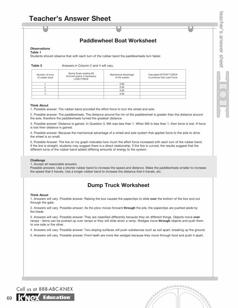
Paddlewheel Boat Worksheet
teacher’s answer sheet
ObservationsTable 1Students should observe that with each turn of the rubber band the paddlewheels turn faster.
Number of turns of rubber band
Spring Scale reading (N) (Convert grams if necessary)
LOAD FORCE
Mechanical Advantage of the system
Calculated EFFORT FORCE to produce that Load Force
1234
0.060.060.060.06
Think About1. Possible answer: The rubber band provided the effort force to turn the wheel and axle.
2. Possible answer: The paddlewheels. The distance around the rim of the paddlewheel is greater than the distance around the axle, therefore the paddlewheels turned the greatest distance.
3. Possible answer: Distance is gained. In Question 3, MA was less than 1. When MA is less than 1, then force is lost. If force is lost then distance is gained.
4. Possible answer: Because the mechanical advantage of a wheel and axle system that applies force to the axle to drive the wheel is so small.
5. Possible Answer: The line on my graph indicates how much the effort force increased with each turn of the rubber band. If the line is straight, students may suggest there is a direct relationship. If the line is curved, the results suggest that the different turns of the rubber band added differing amounts of energy to the system.
Challenge1. Accept all reasonable answers. Possible answers: Use a shorter rubber band to increase the speed and distance. Make the paddlewheels smaller to increase the speed that it travels. Use a longer rubber band to increase the distance that it travels, etc.
Dump Truck Worksheet
Think About1. Answers will vary. Possible answer: Raising the box caused the paperclips to slide over the bottom of the box and out through the gate.
2. Answers will vary. Possible answer: As the plow moves forward through the pile, the paperclips are pushed aside by the blade.
3. Answers will vary. Possible answer: They are classified differently because they do different things. Objects move over ramps - items can be pushed up over ramps or they will slide down a ramp. Wedges move through objects and push them to one side or the other.
4. Answers will vary. Possible answer: Two sloping surfaces will push substances such as soil apart, breaking up the ground.
5. Answers will vary. Possible answer: Front teeth are more like wedges because they move through food and push it apart.
Table 2 Answers in Column 2 and 4 will vary.
Call us at 888-ABC-KNEX
69
Teacher’s Answer Sheet
Education®
Inclined Plane Worksheet
teacher’s answer sheet
ObservationsLength of ramp: 33 cm
Height of ramp: 7.5 cm
Ideal MA = 4.4
Load Force: Answers will vary.
Prediction: Answers will vary.
Effort force used to pull the weight to the top of ramp: Answers will vary.
Actual MA = Answers will vary.
Think About1. Friction and/or experimental or equipment error.
2. Answers will vary. Possible answer: Inclined planes make work easier by reducing the amount of force needed to raise an object.
3. Answers will vary. Possible answer: The trade-off for using less force is exerting the smaller force over a greater distance.
Challenge1. Answers will vary. Possible answer: Increasing the length of the ramp while keeping its height the same.
2. Answers will vary.
Archimedes’ Screw WorksheetObservationsLength of inclined plane: Approx. 45 cm
Length of cylinder: Approx. 32 cm
Turning the handle: Answers will vary. Possible answer: Turning the handle of the screw pushes the ball up the ramp.
Think About1. Answers will vary. Possible answer: Force applied to the crank turns the screw. As the screw turns, the inclined plane of the screw exerts force on the ball and pushes it up the ramp.
2. Answers will vary. Possible answer: Since the length of the inclined plane wrapped around the cylinder is longer than the length of the cylinder, then force is gained at the expense of distance.
3. Possible answer: Increase the number of threads or turns on a screw.
4. Answers will vary. Possible answers: Farmers put the end of the Archimedes’ Screw in a river or canal. When they turned the crank, water was pushed up the screw from the river to higher ground where their fields were located.
5. Possible answers: Grain elevator; pet food feed; pelletized fuel feed; pill conveyor; ‘worm’ drives; drills.
6. Answers will vary. Possible answer: An Archimedes’ Screw is used to move loose material. A screw used as a fas-tener holds solid surfaces together.
ChallengeAnswers will vary. Possible answer: Student responses should include modifications that enclose the screw and alter the inclined plane to make it solid.
exploring machines
www.knexeducat ion.com
70
Teacher’s Answer Sheet
Education®
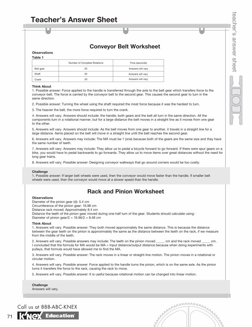
teacher’s answer sheet
Observations
Think About1. Possible answer: Force applied to the handle is transferred through the axle to the belt gear which transfers force to the conveyor belt. The force is carried by the conveyor belt to the second gear. This causes the second gear to turn in the same direction.
2. Possible answer: Turning the wheel using the shaft required the most force because it was the hardest to turn.
3. The heavier the belt, the more force required to turn the crank.
4. Answers will vary. Answers should include: the handle, both gears and the belt all turn in the same direction. All the components turn in a rotational manner, but for a large distance the belt moves in a straight line as it moves from one gear to the other.
5. Answers will vary. Answers should include: As the belt moves from one gear to another, it travels in a straight line for a large distance. Items placed on the belt will move in a straight line until the belt reaches the second gear.
6. Answers will vary. Answers may include: The MA must be 1 (one) because both of the gears are the same size and they have the same number of teeth.
7. Answers will vary. Answers may include: They allow us to pedal a bicycle forward to go forward. If there were spur gears on a bike, you would have to pedal backwards to go forwards. They allow us to move items over great distances without the need for long gear trains.
8. Answers will vary. Possible answer: Designing conveyor walkways that go around corners would be too costly.
Challenge 1. Possible answer: If larger belt wheels were used, then the conveyor would move faster than the handle. If smaller belt wheels were used, then the conveyor would move at a slower speed than the handle.
Observations Diameter of the pinion gear (d): 5.4 cmCircumference of the pinion gear: 16.96 cmDistance rack moved: Approximately 8.4 cmDistance the teeth of the pinion gear moved during one-half turn of the gear. Students should calculate using: Diameter of pinion gear/2 = 16.96/2 = 8.48 cm
Think About1. Answers will vary. Possible answer: They both moved approximately the same distance. This is because the distance between the gear teeth on the pinion is approximately the same as the distance between the teeth on the rack, if we measure from the middle of the teeth.
2. Answers will vary. Possible answers may include: The teeth on the pinion moved _____ cm and the rack moved _____ cm. I concluded that the formula for MA would be MA = Input distance/output distance because when doing experiments with pulleys, that formula would have allowed me to find the MA.
3. Answers will vary. Possible answer: The rack moves in a linear or straight-line motion. The pinion moves in a rotational or circular motion.
4. Answers will vary. Possible answer: Force applied to the handle turns the pinion, which is on the same axle. As the pinion turns it transfers the force to the rack, causing the rack to move.
5. Answers will vary. Possible answer: It is useful because rotational motion can be changed into linear motion.
Rack and Pinion Worksheet
ChallengeAnswers will vary.
Number of Complete Rotations Time (seconds)
Belt gear
Shaft
Crank
20
20
20
Answers will vary
Answers will vary
Answers will vary
Table 1
Call us at 888-ABC-KNEX
71
Teacher’s Answer Sheet
Conveyor Belt Worksheet
Education®
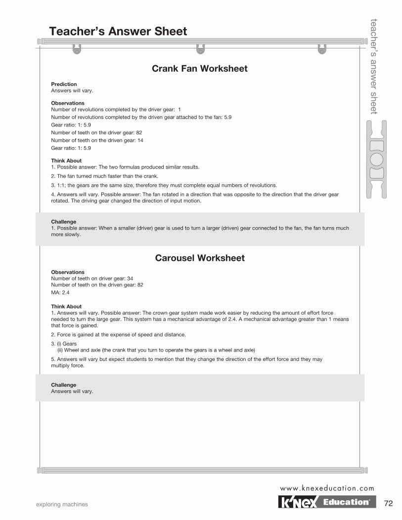
Teacher’s Answer Sheet
Crank Fan Worksheet
teacher’s answer sheet
Prediction Answers will vary.
ObservationsNumber of revolutions completed by the driver gear: 1
Number of revolutions completed by the driven gear attached to the fan: 5.9
Gear ratio: 1: 5.9
Number of teeth on the driver gear: 82
Number of teeth on the driven gear: 14
Gear ratio: 1: 5.9
Think About1. Possible answer: The two formulas produced similar results.
2. The fan turned much faster than the crank.
3. 1:1; the gears are the same size, therefore they must complete equal numbers of revolutions.
4. Answers will vary. Possible answer: The fan rotated in a direction that was opposite to the direction that the driver gear rotated. The driving gear changed the direction of input motion.
Challenge1. Possible answer: When a smaller (driver) gear is used to turn a larger (driven) gear connected to the fan, the fan turns much more slowly.
Carousel WorksheetObservationsNumber of teeth on driver gear: 34 Number of teeth on the driven gear: 82
MA: 2.4
Think About1. Answers will vary. Possible answer: The crown gear system made work easier by reducing the amount of effort force needed to turn the large gear. This system has a mechanical advantage of 2.4. A mechanical advantage greater than 1 means that force is gained.
2. Force is gained at the expense of speed and distance.
3. (i) Gears (ii) Wheel and axle (the crank that you turn to operate the gears is a wheel and axle)
5. Answers will vary but expect students to mention that they change the direction of the effort force and they may multiply force.
ChallengeAnswers will vary.
exploring machines
www.knexeducat ion.com
72Education®
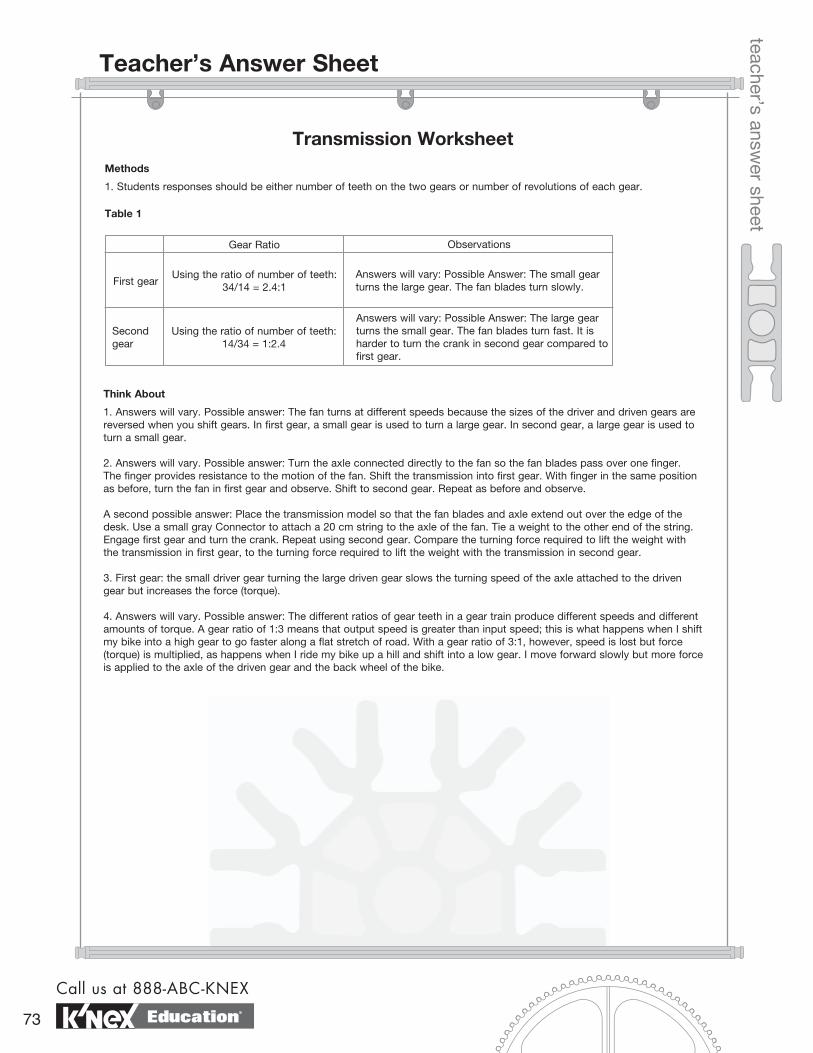
Teacher’s Answer Sheet
Transmission Worksheet
teacher’s answer sheet
Methods
1. Students responses should be either number of teeth on the two gears or number of revolutions of each gear.
Table 1
Gear Ratio Observations
First gear
Second gear
Using the ratio of number of teeth: 34/14 = 2.4:1
Using the ratio of number of teeth: 14/34 = 1:2.4
Answers will vary: Possible Answer: The small gear turns the large gear. The fan blades turn slowly.
Answers will vary: Possible Answer: The large gear turns the small gear. The fan blades turn fast. It is harder to turn the crank in second gear compared to first gear.
Think About
1. Answers will vary. Possible answer: The fan turns at different speeds because the sizes of the driver and driven gears are reversed when you shift gears. In first gear, a small gear is used to turn a large gear. In second gear, a large gear is used to turn a small gear.
2. Answers will vary. Possible answer: Turn the axle connected directly to the fan so the fan blades pass over one finger. The finger provides resistance to the motion of the fan. Shift the transmission into first gear. With finger in the same position as before, turn the fan in first gear and observe. Shift to second gear. Repeat as before and observe.
A second possible answer: Place the transmission model so that the fan blades and axle extend out over the edge of the desk. Use a small gray Connector to attach a 20 cm string to the axle of the fan. Tie a weight to the other end of the string. Engage first gear and turn the crank. Repeat using second gear. Compare the turning force required to lift the weight with the transmission in first gear, to the turning force required to lift the weight with the transmission in second gear.
3. First gear: the small driver gear turning the large driven gear slows the turning speed of the axle attached to the driven gear but increases the force (torque).
4. Answers will vary. Possible answer: The different ratios of gear teeth in a gear train produce different speeds and different amounts of torque. A gear ratio of 1:3 means that output speed is greater than input speed; this is what happens when I shift my bike into a high gear to go faster along a flat stretch of road. With a gear ratio of 3:1, however, speed is lost but force (torque) is multiplied, as happens when I ride my bike up a hill and shift into a low gear. I move forward slowly but more force is applied to the axle of the driven gear and the back wheel of the bike.
Call us at 888-ABC-KNEX
73 Education®