ACTIVE VIBRATION CONTROL TO ATTENUATE HAND- ARM … · ACTIVE VIBRATION CONTROL TO ATTENUATE HAND-...
46
ACTIVE VIBRATION CONTROL TO ATTENUATE HAND- ARM VIBRATION FOR ORBITAL SANDER AHMAD ZHAFRAN BIN AHMAD MAZLAN 2012
Transcript of ACTIVE VIBRATION CONTROL TO ATTENUATE HAND- ARM … · ACTIVE VIBRATION CONTROL TO ATTENUATE HAND-...

ACTIVE VIBRATION CONTROL TO ATTENUATE HAND-
ARM VIBRATION FOR ORBITAL SANDER
AHMAD ZHAFRAN BIN AHMAD MAZLAN
2012

ACTIVE VIBRATION CONTROL TO ATTENUATE HAND-ARM
VIBRATION FOR ORBITAL SANDER
by
AHMAD ZHAFRAN BIN AHMAD MAZLAN
Thesis submitted in fulfilment of the requirements
for the degree of
Master of Science
October 2012

DECLARATION
I hereby declare that the work reported in this thesis is the result of my own
investigation and that no part of the thesis has been plagiarized from external sources.
Materials taken from other sources are duly acknowledgement by giving explicit
references.
Signature:
Name of student: AHMAD ZHAFRAN BIN AHMAD MAZLAN
Matrix number: P-CM0320
Date: 4 October 2012
ii
ACKNOWLEDGEMENTS
First of all, my highness praises and all thanks to Almighty Allah Subhanahu
Wataalla, the Most Gracious the Most Merciful, who gives me the patience,
knowledge and courage to complete this research.
I would like to express my sincere gratitude to my research supervisor, Prof.
Dr. Zaidi bin Mohd Ripin, who gives me a constant encouragement, good guidance
and suggestions all the way of this research. Without him, this research will not be
the same as presented here.
I also want to extend my gratitude to the technicians especially Mr. Wan
Mohd Amri bin Wan Mamat Ali, who always work with me for the experimental
works. Apart of that, I want to thank to all my fellow friends from the Vibration
Laboratory whose give their help, moral support, and some valuable hints for
completing my research.
Beside that, I am gratitude to Kementerian Pengajian Tinggi Malaysia and
Universiti Sains Malaysia for awarding me Skim Latihan Akademik Bumiputera
(SLAB) scholarship which assisted my financial.
Last but not least, I would like to express my deepest gratitude to my wife,
Mrs. Fauziah binti Abdullah, my children; Iqbal Zayyaan and Iqbal Rizqin, and my
whole family for their kindly love and continuous support during my intricate times
in completing this research.
AHMAD ZHAFRAN BIN AHMAD MAZLAN
October 2012

iii
TABLE OF CONTENTS
Page
ACKNOWLEDGEMENTS ii
TABLE OF CONTENTS
iii
LIST OF TABLES
vii
LIST OF FIGURES
viii
LIST OF SYMBOLS
xii
LIST OF NOTATIONS
xvi
LIST OF APPENDICES
xviii
LIST OF PUBLICATIONS
xviii
ABSTRAK
xix
ABSTRACT
xx
CHAPTER 1: INTRODUCTION
1
1.1 Background study 1
1.2 Problem statement
3
1.3 Motivation of the work
4
1.4 Objectives 4
1.5 Scope 4
1.6 Thesis outlines 5
CHAPTER 2: LITERATURE REVIEW
6
2.1 Overview
6
2.2 Hand-arm vibration syndrome (HAVs) and the epidemiological studies
6
2.3 The guidelines to protect and measure hand-arm vibration
8
2.3.1 Guidelines and references for hand-transmitted vibration 8

iv
2.3.2 Standard measurement of hand-transmitted vibration
9
2.4 Modeling of hand-held power tools
12
2.5 Human hand-arm biodynamic models
13
2.5.1 To-the-hand biodynamic models
13
2.5.2 Through-the-hand biodynamic models
15
2.6 Coupled power tool-hand-arm models 15
2.7 Attenuation of hand-transmitted vibration 16
2.7.1 Vibration isolation approaches
17
2.7.2 Vibration absorption approaches
19
2.7.3 Active vibration control (AVC) approaches
20
2.7.3.1 Active force control (AFC) technique
23
2.8 Discussion
24
2.9 Summary
27
CHAPTER 3: METHODOLOGY
28
3.1 Overview
28
3.2 Orbital sander specification and description
28
3.3 Determination of the sensor and actuator locations
30
3.4 Measurement of the input spectrum
31
3.4.1 Free-free condition
31
3.4.2 The operating condition
31
3.5 Experimental modal analysis
33
3.6 Model development and verification
34
3.6.1 Modal mass, stiffness and damping
35
3.6.2 Modal parameters
36
3.6.3 Model validation 37

v
3.7 Mathematical model of the orbital sander
38
3.7.1 Matlab coding development
39
3.7.2 Simulink diagram development
41
3.8 Model of active vibration control (AVC) system for the orbital sander
43
3.8.1 Active system with PID controller
44
3.8.1.1 Simulink diagram development
46
3.8.2 Active system with PID+AFC controller
47
3.8.2.1 Simulink diagram development
49
3.9 Disturbances
51
3.10 Mathematical model of the hand-arm system
51
3.10.1 Simulink diagram development
53
3.11 Development of the coupled orbital sander-hand-arm model
54
3.11.1 Simulink diagram development
55
3.12 Summary
57
CHAPTER 4: RESULTS AND DISCUSSION
58
4.1 Overview
58
4.2 Input spectrum result of the orbital sander
58
4.2.1 Free-free condition
58
4.2.2 The operating condition
60
4.3 Experimental modal analysis
66
4.3.1 Modes of vibration in the z-axis direction
66
4.4 Model validation
70
4.5 Simulation result of the orbital sander
73
4.5.1 Matlab and Simulink results
73

vi
4.5.2 Comparison of the simulation result
75
4.6 Simulation result of the active system
76
4.6.1 Tuning of the PID controller
77
4.6.2 Tuning of the AFC controller
79
4.7 Performance evaluation
81
4.7.1 Performance of the orbital sander model using various control schemes
81
4.7.2 Performance of the coupled orbital sander-hand-arm model
83
4.7.3 Performance of the system with the presence of external disturbance
85
CHAPTER 5: CONCLUSION
88
5.1 Conclusion
88
5.2 Recommendation for future work
89
REFERENCES
90
APPENDICES
98
Appendix A: Hand-arm vibration reference chart
98
Appendix B: Mathematical model of the orbital sander (Matlab coding)
99
Appendix C: Mathematical model of the passive and active systems of the orbital sander (Simulink digram)
101
Appendix D: Overall mathematical model of coupled orbital sander-hand- arm model (Simulink diagram)
103
Appendix E: Model and simulation parameters (Matlab and Simulink)
107
Appendix F: Performance of coupled orbital sander-hand-arm model with various control schemes
108
PUBLICATIONS 111

vii
LIST OF TABLES
Page
1.1 The literatures of the high vibration level power tools
1
3.1 Technical data Bosch GSS 230 Professional Orbital Sander
30
3.2 Reynolds and Soedel, (1972) single-degree-of-freedom model parameters in the xh, yh and zh-axis direction (f >100 Hz) (Rakheja, et al., 2002)
52
3.3 Parts and its function in the Simulink diagram
57
4.1 Output acceleration of front and rear handle in the three axes (x, y and z-axis) with various push forces
63
4.2 Frequency-weighted acceleration of the orbital sander front handle in the three axes with various push forces
65
4.3 Compact mode complexity for z-axis direction of the orbital sander
68
4.4 Modal mass, stiffness and damping for the orbital sander
70
4.5 Comparison of acceleration output for the orbital sander model using various control schemes
83
4.6 Comparison of acceleration output for the coupled orbital sander-hand-arm model using various control schemes
85
4.7 Acceleration output of the orbital sander and the coupled orbital sander-hand-arm model in two different conditions using various control schemes
87

viii
LIST OF FIGURES
Page
2.1 The example of Vibration White Finger (VWF) disease (Hunter, 2011)
7
2.2 Biodynamic and basicentric coordinate system for flat-palm position (ISO 5349-1, 2001)
10
2.3 Frequency-weighting filter (Wh) with band limitation for hand-transmitted vibration (ISO 5349-1, 2001)
11
2.4 Cross section diagram and dynamic model of pneumatic hammer (Golysheva, et al., 2004)
12
2.5 Anti-vibration glove used to attenuate hand-arm vibration when using the orbital sander (Lee Valley, 2012)
18
2.6 Anti-vibration side handle (Makita, 2012a)
19
2.7 Basic control diagram for AVC system (Stienecker, 2011)
21
3.1 The flow chart of overall approach of this research
29
3.2 Bosch GSS 230 Professional Orbital Sander
28
3.3 Orbital sander free-free condition experiment set-up with detail view of tri-axial accelerometer (B&K 4506)
31
3.4 Signal analyzer device (iMC, cs-8008) and dynamometer amplifier (Kistler, type 9272)
32
3.5 Measurement set-up of the orbital sander input spectrum
32
3.6 Orbital sander geometry modeling in LMS software
33
3.7 Experimental set-up for impact testing
34
3.8 A three-degree-of-freedom modal model of the orbital sander
38
3.9 Full Simulink diagram of the passive system of the orbital sander
42
3.10 Shear actuator to be used for AVC system (A=B=10 mm, L=23 mm) (Physik Instruments, 2009b)
44
3.11 Full Simulink diagram of the active system with PID controller for the orbital sander
47

ix
3.12 The overall dynamic system with an input of AFC technique
49
3.13 Full Simulink diagram of active system with PID+AFC controller for the orbital sander
50
3.14 A single-degree-of-freedom hand-arm model
52
3.15 Full Simulink diagram of the passive system of the hand-arm model
53
3.16 Model of the coupled orbital sander-hand-arm with AVC system
55
3.17 Full Simulink diagram of the active system with PID+AFC controller for the coupled orbital sander-hand-arm model
56
4.1 The FFT of the acceleration in the x, y and z-axis direction of the orbital sander front handle when in the free-free condition
59
4.2 The FFT of the acceleration in the x, y and z-axis direction of the orbital sander rear handle when in the free-free condition
59
4.3 The push force (internal disturbance, F) graph in z-axis direction when operating the orbital sander (time domain)
61
4.4 The FFT graph of the push force (internal disturbance, F) in the z-axis direction when operating the orbital sander
62
4.5 The FFT of the acceleration in the x, y and z-axis of the orbital sander front handle when sanding with 22.7 N of push force
63
4.6 The comparison of output acceleration in the x, y and z-axis direction of the front and rear handle with various sanding push force
64
4.7 The comparison of frequency-weighted acceleration in the x, y and z-axis of the orbital sander front handle with various sanding push forces
65
4.8 The FRF graph of the experimental modal analysis in the z-axis direction of the orbital sander with "Polymax" function
67
4.9 Comparison of modal assurance criterion (MAC) between each mode of the orbital sander in the z-axis direction
69
4.10 Mode deflection shapes of the orbital sander in z-axis direction
69
4.11 The validation of FRF graph between experiment and model of the orbital sander (acceleration)
71
4.12 The comparison of acceleration output A(ω) between experiment 72

x
and model of the orbital sander
4.13 The output acceleration of the orbital sander when subjected to the input force as in Figure 4.3 (time domain)
74
4.14 The output acceleration of the orbital sander when subjected to the input force as in Figure 4.3 (frequency domain)
74
4.15 The comparison of acceleration output between simulation and actual experiment result of the orbital sander (time domain)
75
4.16 The comparison of acceleration output between simulation and actual experiment result of the orbital sander (frequency domain)
76
4.17 Displacement result for different values of KP and KD with a step input reference signal for the PD scheme
78
4.18 Error signals for different values of KP and KD with a step input reference signal for the PD scheme
78
4.19 Displacement result for different values of estimated masses (M*) with a step input reference signal for the PD+AFCCA scheme
79
4.20 Error signals of estimated masses (M*=0.8 kg) with a step input reference signal for the PD+AFCCA scheme
80
4.21 Comparison of acceleration output between passive, PD and PD+AFCCA model for the orbital sander (time domain)
82
4.22 Comparison of acceleration output between passive, PD and PD+AFCCA model for the orbital sander (frequency domain)
82
4.23 Comparison of acceleration effect on the hand-arm system between passive, PD and PD+AFCCA model for the orbital sander (time domain)
84
4.24 Comparison of acceleration effect on the hand-arm system between passive, PD and PD+AFCCA model for the orbital sander (frequency domain)
84
4.25 Acceleration output of the orbital sander and the coupled orbital sander-hand-arm model in two different conditions using various control schemes
87
A.1 Hand-arm vibration quick reference chart (HSC, 2005)
98
C.1 Simulink diagram of the m1 subsystem of the orbital sander
101
C.2 Simulink diagram of the m2 subsystem of the orbital sander
102
xi
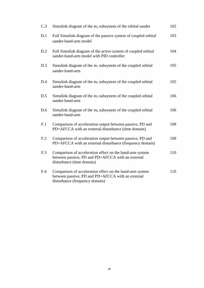
C.3 Simulink diagram of the m3 subsystem of the orbital sander
102
D.1 Full Simulink diagram of the passive system of coupled orbital sander-hand-arm model
103
D.2 Full Simulink diagram of the active system of coupled orbital sander-hand-arm model with PID controller
104
D.3 Simulink diagram of the m1 subsystem of the coupled orbital sander-hand-arm
105
D.4 Simulink diagram of the m2 subsystem of the coupled orbital sander-hand-arm
105
D.5 Simulink diagram of the m3 subsystem of the coupled orbital sander-hand-arm
106
D.6 Simulink diagram of the mh subsystem of the coupled orbital sander-hand-arm
106
F.1 Comparison of acceleration output between passive, PD and PD+AFCCA with an external disturbance (time domain)
108
F.2 Comparison of acceleration output between passive, PD and PD+AFCCA with an external disturbance (frequency domain)
109
F.3 Comparison of acceleration effect on the hand-arm system between passive, PD and PD+AFCCA with an external disturbance (time domain)
110
F.4 Comparison of acceleration effect on the hand-arm system between passive, PD and PD+AFCCA with an external disturbance (frequency domain)
110

xii
LIST OF SYMBOLS
Symbols Descriptions Unit
A(ω) Calculated acceleration m/s2
A(8)
Daily vibration exposure based on reference period of 8 hours
m/s2
Ai A scaling constant for the ith mode
-
ahv Total frequency-weighted acceleration
m/s2
ahwx Overall weighted RMS acceleration in x-axis m/s2
ahwy Overall weighted RMS acceleration in y-axis m/s2
ahwz Overall weighted RMS acceleration in z-axis m/s2
[C] (DOFs by DOFs) Damping matrix
kg/s
ca Damping of the piezo actuator
kg/s
ch Damping of the hand-arm system
kg/s
ci Modal damping at each mode (i)
kg/s
c1 Modal damping 1 of the orbital sander
kg/s
c2 Modal damping 2 of the orbital sander
kg/s
c3 Modal damping 3 of the orbital sander
kg/s
[⋱c⋱] (Modes by modes) Modal damping matrix kg/s
D(s) Denominator of orbital sander transfer function
-
D1(s) Numerator 1 of the orbital sander transfer function
-
D2(s) Numerator 2 of the orbital sander transfer function
-
D3(s) Numerator 3 of the orbital sander transfer function
-
e(t) Error signal m
E(s) Transfer function error signal m
F(s) Complex quantity of input force N
xiii
F Internal disturbance of the orbital sander N
F* Estimated disturbance force N
Fa Force of the piezo actuator N
Fe External disturbance of the orbital sander N
Fa* Total force of the piezo actuator N
Gc(s) PID controller transfer function
-
H(ω) Transfer function/ FRF of the orbital sander (m/s2)/N
ith Modes -
[K] (DOFs by DOFs) Stiffness matrix
N/m
KD Derivative gain -
KI Integrator gain -
KP Proportional gain -
ka Stiffness of the piezo actuator
N/m
kh Stiffness of the hand-arm system
N/m
ki Modal stiffness at each mode (i)
N/m
k1 Modal stiffness 1 of the orbital sander
N/m
k2 Modal stiffness 2 of the orbital sander
N/m
k3 Modal stiffness 3 of the orbital sander
N/m
[⋱k⋱] (Modes by modes) Modal stiffness matrix N/m
L Shear piezo actuator thickness mm
[M] (DOFs by DOFs) Mass matrix
kg
M* Estimated mass kg
ma Mass of the piezo actuator
kg
mh Mass of the hand-arm system kg
mi
Modal mass at each mode (i) kg

xiv
m1 Modal mass 1 of the orbital sander kg
m2 Modal mass 2 of the orbital sander kg
m3 Modal mass 3 of the orbital sander kg
[⋱m⋱] (Modes by modes) Modal mass matrix kg
(r) Correlation coefficient -
r(t) Reference output m
[r(i)] (DOFs by DOFs) Residue matrix for the ith mode
-
s Complex number in magnitude and phase
-
T Total daily vibration exposure h
T(s) Complex quantity of vibration transmissibility
-
T0 Reference duration of 8 hours h
{uk} Mode shape of the ith mode
-
{uk}t Transpose mode shape of the ith mode
-
Wh Frequency-weighting filter
-
ωi Damped natural frequency of the ith mode
Hz
X(s) Complex quantity of resulting displacement m
X0(s) Complex quantity of excitation displacement m
X(s)
Complex quantity of resulting velocity m/s
X0(s) Complex quantity of excitation velocity m/s
X(s) Complex quantity of resulting acceleration m/s2
X0(s) Complex quantity of excitation acceleration m/s2
Za(s) Resulting displacement of the piezo actuator transfer function m
ZD(s) Complex quantity of DPMI N/(m/s2)
za Resulting displacement of the piezo actuator m
ze Experimental FRF data
(m/s2)/N

xv
zh Resulting displacement of the hand-arm system m
zi Resulting displacement of ith modal mass of the sander m
zm Model FRF data
(m/s2)/N
z1 Resulting displacement of modal mass 1 of the orbital sander m
z2 Resulting displacement of modal mass 2 of the orbital sander
m
z3 Resulting displacement of modal mass 3 of the orbital sander m
��𝑧a Resulting velocity of the piezo actuator m/s
��𝑧h Resulting velocity of the hand-arm system m/s
��𝑧1 Resulting velocity of modal mass 1 of the orbital sander m/s
��𝑧2 Resulting velocity of modal mass 2 of the orbital sander m/s
��𝑧3 Resulting velocity of modal mass 3 of the orbital sander m/s
��𝑧a Resulting acceleration of the piezo actuator m/s2
��𝑧h Resulting acceleration of the hand-arm system m/s2
��𝑧1 Resulting acceleration of modal mass 1 of the orbital sander m/s2
��𝑧2 Resulting acceleration of modal mass 2 of the orbital sander m/s2
��𝑧3 Resulting acceleration of modal mass 3 of the orbital sander m/s2
𝑧𝑧𝑒𝑒� Average value of all experimental FRF data
(m/s2)/N
𝑧𝑧𝑚𝑚���� Average value of all model FRF data
(m/s2)/N
σi Damping coefficient of the ith mode
kg/s
[Φ] (DOFs by modes) Mode shape matrix -
[Φ] t (DOFs by modes) Transpose mode shape matrix -

xvi
LIST OF NOTATIONS
Symbols
Descriptions
AFC Active Force Control
AFCCA Active Force Control with Crude Approximation
AVC Active Vibration Control
B&K Bruel and Kjaer
CEACS Combined Energy and Attitude Control System
CTS Carpal Tunnel Syndrome
DPMI Dynamic-point Mechanical Impedance
DVA Dynamic Vibration Absorber
EAV Exposure Action Value
ELV Exposure Limit Value
EU European Union
FE Finite Element
FFT Fast Fourier Transform
FL Fuzzy Logic
FRF Frequency Response Function
GA Genetic Algorithm
HAVs Hand-arm Vibration Syndrome
HSC Health and Safety Commission
ILM Iterative Learning Method
ISO International Standardization Organization
LQG Linear Quadratic Gaussian
MAC Modal Assurance Criterion
MDOF Multi-degree-of-freedom

xvii
MP Mode Participant
NIWF National Institute of Working Life
NN Neural Network
OPERC Off-highway Plant and Equipment Research Centre
PID Proportional-integral-derivative
PD Proportional-derivative
RMS Root Mean Squares
R&S Reynolds and Soedel
SDOF Single-degree-of-freedom
TVA Tuned Vibration Absorber
VWF Vibration White Finger
xviii
LIST OF APPENDICES
Page
A Hand-arm vibration reference chart
98
B Mathematical model of the orbital sander (Matlab coding)
99
C Mathematical model of the passive and active systems of the orbital sander (Simulink digram)
101
D Overall mathematical model of coupled orbital sander-hand-arm model (Simulink diagram)
103
E Model and simulation parameters (Matlab and Simulink)
107
F Performance of coupled orbital sander-hand-arm model with various control schemes
108
LIST OF PUBLICATIONS
Page
1 Development of active vibration control cancellation pad for orbital sander
112

xix
KAWALAN GETARAN AKTIF UNTUK MELEMAHKAN GETARAN TANGAN UNTUK MESIN PENGGILAP ORBIT
ABSTRAK
Penggunaan mesin penggilap orbit yang berterusan pada tahap getaran yang
tinggi boleh menyumbang kepada sindrom getaran tangan. Untuk mengkaji
pengurangan getaran tangan apabila menggunakan mesin penggilap orbit, analisis
dinamik bagi mesin penggilap orbit telah dilakukan dengan menggunakan model
pasangan mesin penggilap orbit dan tangan tertakluk kepada pad kawalan getaran
aktif. Mesin penggilap orbit telah direka sebagai satu sistem dengan tiga darjah
kebebasan di mana nilai-nilai bagi ragaman jisim, kekakuan dan redaman diperolehi
daripada eksperimen analisis ragaman dan model Reynolds dan Soedel dengan
darjah kebebasan tunggal telah dipilih untuk dijadikan model tangan. Pelbagai skim
kawalan telah digunakan di dalam sistem kawalan getaran aktif termasuklah teknik
kawalan terbitan berkadar dan kawalan daya aktif. Parameter reka bentuk yang
dianalisis termasuklah lokasi penderia dan penggerak dan juga penggunaan model.
Dua jenis gangguan telah dikenakan pada sistem di mana gangguan pertama di ukur
semasa mengendalikan mesin penggilap orbit manakala gangguan kedua telah direka
sebagai gelombang sinus untuk menguji tahap keberkesanan skim-skim kawalan
yang telah digunakan. Keputusan simulasi menunjukkan bahawa skim kawalan yang
menggunakan teknik kawalan daya aktif menghasilkan keputusan yang lebih baik
walaupun di bawah pengaruh gangguan luar dengan pengurangan getaran tangan
sebanyak 99.20 % berbanding dengan skim kawalan terbitan berkadar yang
mengurangkan getaran tangan sebanyak 88.36 %. Keputusan ini juga membuktikan
bahawa kawalan getaran aktif merupakan teknik yang efisien untuk mencapai
getaran tangan yang rendah pada mesin penggilap orbit.
xx
ACTIVE VIBRATION CONTROL TO ATTENUATE HAND-ARM VIBRATION FOR ORBITAL SANDER
ABSTRACT
Prolonged use of the orbital sander with high vibration level can lead to the
hand-arm vibration syndrome (HAVs). In order to evaluate the attenuation of the
hand-arm vibration when using the orbital sander, dynamic analysis of the orbital
sander is carried out using coupled orbital sander-hand-arm model subjected to the
active vibration control (AVC) pad. The orbital sander is modelled as a three-degree-
of-freedom system where the values of the modal mass, stiffness and damping are
derived from the experimental modal analysis and the single-degree-of-freedom of
Reynolds and Soedel model is chosen to represent the hand-arm system. Various
control schemes are applied in the AVC system including proportional-derivative
(PD) and active force control (AFC) techniques. The design parameters analyzed
include the sensor and the actuator locations and the modelling approach. Two
disturbances are created for the system where the first disturbance is measured from
the orbital sander operating condition and the second disturbance is modelled as a
sine wave to test the robustness of the control schemes. The simulation result shows
that the control scheme with AFC input produces a superior result even though under
the influence of external disturbance with a reduction of 99.20 % of hand-arm
vibration compared to the classical PD controller which reduces only 88.36 % of
hand-arm vibration. The results also proved that the AVC pad is an effective way of
achieving a low hand-arm vibration for the orbital sander.

1
CHAPTER 1
INTRODUCTION
1.1 Background study
Prolonged use of the power tools with high vibration level may expose the
workers to the hand-arm vibration syndrome (HAVs). This syndrome is an
association of the vascular and nonvascular disorder in the human hand-arm system
(Bovenzi, 1998; Mansfield, 2005).
Researchers have evaluated the vibration level (frequency-weighted
acceleration) of several power tools such as orbital sander, rock drill, pneumatic
hammer and grass trimmer. The result shows that all these tools produced a high
level of vibration. The detail of the literatures and the evaluated power tools are
shown in Table 1.1.
Table 1.1: The literatures of the high vibration level power tools
Power tools Weighted
acceleration (ahv) Researchers
Orbital sander 3.9 ~ 7.3 m/s2 (Cherian, et al., 1996; Bovenzi, et al., 2005;
Ko, 2008)
Rock drill 24 ~ 25 m/s2 (Niekerk, et al., 1998;
Oddo, et al., 2004) Pneumatic hammer 30 m/s2 (Golysheva, et al., 2004)
Grass trimmer 4.5 ~ 11.3 m/s2 (Ko, et al., 2011a; Ko, et al., 2011b)
International Organization of Standardization (ISO) has produced two
documentations which is ISO 5349-1 (2001) and ISO 5349-2 (2001) for evaluating
the hand-transmitted vibration of the power tools. The European Union (EU) has set
a vibration limit values of 2.5 m/s2 for the Exposure Action Value (EAV) and 5 m/s2
for the Exposure Limit Value (ELV) for daily vibration exposure A(8) (EU, 2002).

2
In order to observe the biodynamic response of the coupled power tool-hand-
arm system, researchers have developed models of the hand-held power tools. Oddo,
et al, (2004) and Golysheva, et al., (2004) developed the model of rock drill
suspended handle and pneumatic hammer, respectively. The developed models can
be used for the advance simulation of the system such as the addition of the control
elements (Hassan, et al., 2010).
Rakheja, et al., (2002) carried out a comprehensive study of the biodynamic
hand-arm models including to-the-hand and through-the-hand models in the study of
dynamic-point mechanical impedance (DPMI) of the hand-arm system and the
response of specific hand-arm segment due to the transmitted vibration. From the
study, there are only three models; Reynolds and Soedel, (1972), Mishoe and Suggs,
(1977) and Miwa, et. al., (1979), which obtained all the natural frequencies in the
range of the formulated frequency and only Reynolds and Soedel, (1972) specified
the range of frequency for each direction of the hand-arm model parameters.
There are two methods of modeling the couple of power tools with the hand-
arm models, depending on the way the tool is handle which is directly in contact with
the hand (Oddo, et al, 2004) or when some intercession material is added in between
(Golysheva, et al., 2004; Ko, 2008). The direct coupling requires the use of four-pole
parameters (Showdown, 1971) to extract the element characteristics between the
tools and the hand-arm models. The second method is by modeling the structure of
the intercession device between the tools and the hand-arm models.
In order to attenuate the hand-transmitted vibration from the power tools,
various techniques are used to control the hand-transmitted vibration including
passive and active control techniques. Passive control involves structural
modification, vibration isolation and vibration absorption approaches (Golysheva, et

3
al., 2004). For cases where the disturbances of the dynamic system vary with time,
passive control becomes ineffective and active vibration control (AVC) has to be
introduced to the system (William, 2007; Hassan, et al., 2010).
There are various kinds of controller scheme which can be applied in AVC
system to suppress the vibration of the tools such as proportional-integral-derivative
(PID), neural network (NN), fuzzy logic (FL) and etc. Active force control (AFC) is
one of the most effective technique in reducing the vibration for AVC system. For
example, Hassan, et al, (2010) in his simulation work proved that AFC is better than
other control techniques in suppressing the vibration of the hedge trimmer handle.
This technique has also been used in robotics (Kwek, et al., 2003; Mailah, et al.,
2009), automotive (Mohamad, 2004; Priyandoko, et al., 2009; Rajeswari and
Lakshmi, 2010), aerospace (Varatharajoo, et al., 2011) and beam applications
(Karagulle, et al., 2004; Knot, et al., 2011).
In this work, the hand-arm coupled with an orbital sander model is developed.
Then, an active vibration control with various control techniques is included in the
system and its efficacy is compared and evaluated.
1.2 Problem statement
Orbital sander is one of the power tools which produces high vibration level
(ahv = 7.3 m/s2) and exceed both EAV and ELV values set by EU, (2002). The
passive control solutions are not fully effective in attenuating the hand-arm vibration
for the orbital sander. Active vibration control (AVC) is one of the methods that can
be used to improve the attenuation of the hand-arm vibration. The effectiveness of
using the AVC pad in attenuating the hand-arm vibration level due to the use of the
orbital sander is studied and evaluated in this work.

4
1.3 Motivation of the work
The applications of the active vibration control (AVC) technique to attenuate
the vibration level of the power tools are rarely being studied. Also, there are no
studies of using the AVC pad approaches to reduce the hand-arm vibration for the
couple orbital sander-hand-arm system. These reasons have motivated this work.
1.4 Objectives
In this research, four objectives are set to be achieved:
• To carry out vibration analysis of the orbital sander
• To develop coupled orbital sander-hand-arm model
• To attenuate hand-arm vibration for the orbital sander using active vibration
control (AVC) pad
• To compare the effectiveness of various control schemes in reducing the
orbital sander vibration
1.5 Scope
This work is focused on measuring the input spectrum of the orbital sander in
two conditions to determine the dominant vibration axis of the orbital sander. Based
on the dominant axis, the experimental modal analysis for the orbital sander is
performed. The validation of the frequency response function and the output
acceleration between experiment and modeled orbital sander is carried out. The
coupled orbital sander-hand-arm model is developed and the comparison between
PD and AFC schemes to attenuate the hand-arm vibration for the orbital sander is
made.

5
1.6 Thesis outlines
This thesis is divided into five chapters which are introduction, literature
review, methodology, results and discussion, and finally conclusion. Chapter One
consists of background study, problem statement, motivation of work, objectives and
scope of the research. Chapter Two describes a comprehensive literatures on hand-
arm vibration syndrome (HAVs), the guidelines of hand-transmitted vibration, hand-
held power tools structure modeling, biodynamic hand-arm models, coupled power
tools-hand-arm model and finally hand-arm vibration attenuation methods. Chapter
Three presents the methodology of current work and the results are discussed in
Chapter Four. Finally, Chapter Five describes the conclusion of this research and
recommendation for future work.

6
CHAPTER 2
LITERATURE REVIEW
2.1 Overview
In this chapter, six main topics are presented as below:
• Hand-arm vibration syndrome (HAVs) and the epidemiological studies
• The guidelines to protect and measure the hand-arm vibration
• Modeling of hand-held power tools
• Human hand-arm biodynamic models
• Coupled power tool-hand-arm models
• Attenuation of hand-transmitted vibration
2.2 Hand-arm vibration syndrome (HAVs) and the epidemiological studies
Prolonged exposure to the hand-transmitted vibration from the power tools
may cause hand-arm vibration syndrome (HAVs) which is the combination of
vascular and non-vascular disorder in the hand-arm system (Bovenzi, 1998;
Mansfield, 2005). The vascular disorder is characterized by Secondary Raynaud's
Disease while the non-vascular is represented by Carpal Tunnel Syndrome (CTS)
(Bovenzi, 1998; Fridén, 2001; Stoyneva, et al., 2003; Mansfield, 2005; Griffin, et al.,
2006).
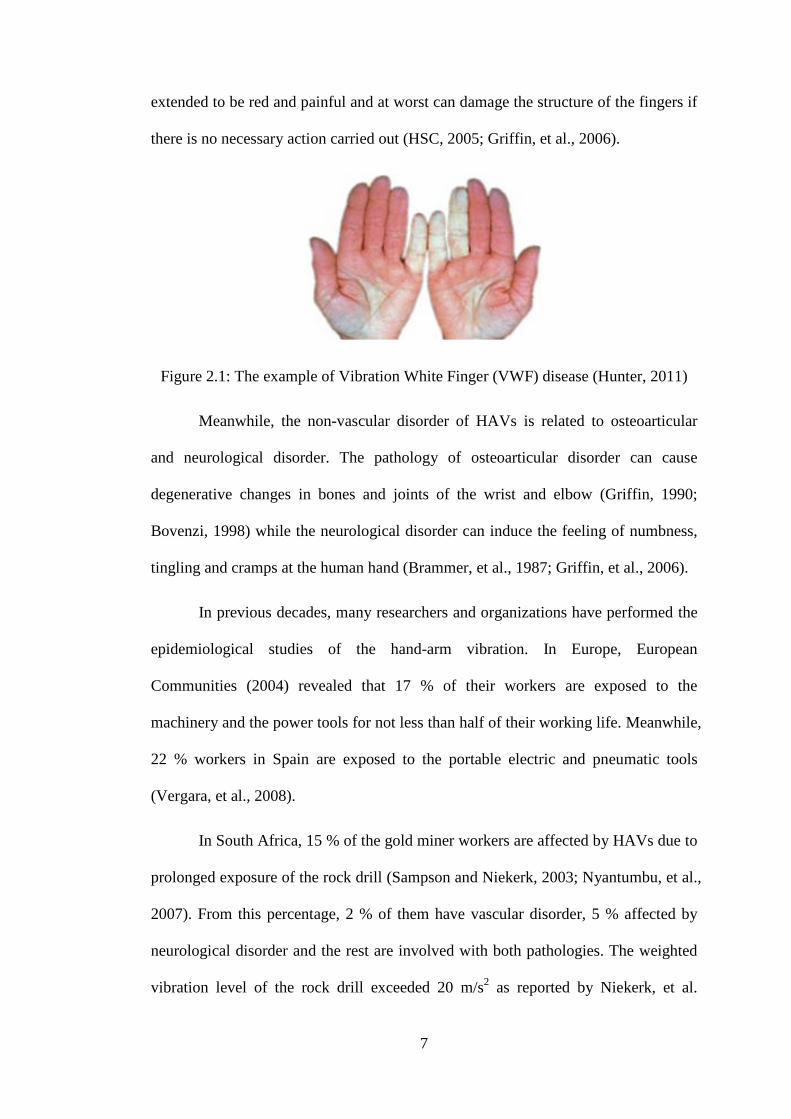
The most common pathology associated with the vascular disorder of HAVs
is Vibration White Finger (VWF). The example of VWF disease is shown in Figure
2.1. In this figure, the symptom of VWF can be identified through the white and pale
signs on the human fingers. If the condition is not improved, these symptoms are
7
extended to be red and painful and at worst can damage the structure of the fingers if
there is no necessary action carried out (HSC, 2005; Griffin, et al., 2006).
Figure 2.1: The example of Vibration White Finger (VWF) disease (Hunter, 2011)
Meanwhile, the non-vascular disorder of HAVs is related to osteoarticular
and neurological disorder. The pathology of osteoarticular disorder can cause
degenerative changes in bones and joints of the wrist and elbow (Griffin, 1990;
Bovenzi, 1998) while the neurological disorder can induce the feeling of numbness,
tingling and cramps at the human hand (Brammer, et al., 1987; Griffin, et al., 2006).
In previous decades, many researchers and organizations have performed the
epidemiological studies of the hand-arm vibration. In Europe, European
Communities (2004) revealed that 17 % of their workers are exposed to the
machinery and the power tools for not less than half of their working life. Meanwhile,
22 % workers in Spain are exposed to the portable electric and pneumatic tools
(Vergara, et al., 2008).
In South Africa, 15 % of the gold miner workers are affected by HAVs due to
prolonged exposure of the rock drill (Sampson and Niekerk, 2003; Nyantumbu, et al.,
2007). From this percentage, 2 % of them have vascular disorder, 5 % affected by
neurological disorder and the rest are involved with both pathologies. The weighted
vibration level of the rock drill exceeded 20 m/s2 as reported by Niekerk, et al.
8
(1998). Burke, et al. (2005) revealed that 15 % from 26,842 workers in the mining
industry suffered with HAVs.
Bovenzi, et al. (2005) carried out epidemiological study on the HAVs effect
to the female workers in Italy, where 19 % of the 100 female workers have CTS and
4 % are involved with vascular disorder. The average weighted vibration of the
orbital sander is reported to be 7.3 m/s2. Neely and Burstrom (2006) found no
differences for the threshold measurement between male and female and Bylund
(2004) showed that both genders received the same power absorption from the hand-
held power tools.
2.3 The guidelines to protect and measure hand-arm vibration
From the previous section, there are various pathology disorders affecting the
human hand-arm due to the transmitted vibration from the power tools. In order to
protect the human hand-arm from these problems, there are the guidelines and the
standards for the measurement of the hand-transmitted vibration.
2.3.1 Guidelines and references for hand-transmitted vibration
In Sweden, National Institute of Working Life (NIWF) (2006) produced the
hand-arm vibration database while the Off-highway Plant and Equipment Research
Centre (HAVTEC-OPERC) (2006) produced the health and safety study module.
Both organizations shared the objectives of measuring the vibration level of hand-
held power tools and revealing the effect of HAVs to the workers.
Based on ISO 5439 (2001), Health and Safety Commission (HSC) (2005) and
Griffin, et al., (2006) produced the guidelines and hand-arm vibration reference chart
for the hand-arm vibration risk assessment. The guidelines improve the previous
version which developed by EU in 2002 (HSE, 2005: Nelson and Brereton, 2005).

9
For the daily vibration exposure A(8), the EU has set the vibration limit values of 2.5
m/s2 for the Exposure Action Value (EAV) and 5 m/s2 for the Exposure Limit Value
(ELV) (EU, 2002). These limit values are based on eight hours of vibration exposure
time. The daily vibration exposure can be calculated by using equation (2.1) (ISO
5349-1, 2001):
A(8) = ahv �T/T0 (2.1)
where,
ahv = Vibration total value.
T = Total daily vibration exposure.
T0 = Reference duration of 8 hours.
The workers who are exposed to the vibration must be alert and have to take a
necessary action to control the vibration if they exceeded the EAV value and must
never reach the ELV limit value (EU, 2002). The detail of the hand-arm vibration
reference chart is shown in Appendix A.
2.3.2 Standard measurement of hand-transmitted vibration
There are four main factors which are emphasized when measuring and
analyzing the hand-arm vibration; (1) vibration axis, (2) vibration frequency, (3)
vibration magnitude and (4) vibration duration (Griffin, 1990; Griffin, et al., 2006).
These factors are known to affect the result of hand-transmitted vibration (Mansfield,
2005). Other factors such as hand posture, contact area, push force as well as grip
force can also influence the hand-transmitted vibration result. The International
Organization of Standardization (ISO) provides the procedures to enable a proper
measurement of the hand-transmitted vibration.

10
The first standard for measurement and assessment of hand-transmitted
vibration is produced in 1986 which is the ISO 5349 (1986). This standard is
reviewed and replaced fifteen years later by ISO 5349 (2001) (Mansfield, 2005). The
new standard consisted of two main parts of the ISO 5349-1 (2001) and ISO 5349-2
(2001). The first part explains the general requirement for measuring hand-
transmitted vibration in multi-axis (x, y and z-axis) direction. For the power tool such
as orbital sander, the position and coordinate system for the multi-axis vibration
measurement at the flat-palm surface is based on Figure 2.2. The figure shows that
the coordinate system for the flat-palm surface is covered both biodynamic and
basicentic coordinates with the x-axis is pointing downward to the base of the orbital
sander, the y-axis is pointing towards the front side of the orbital sander while the z-
axis is parallel with the fingers pointing direction.
Figure 2.2: Biodynamic and basicentric coordinate system for flat-palm position (ISO 5349-1, 2001)
The first part of ISO 5349 (2001) also define the calculation of the frequency-
weighted vibration total value (ahv). This calculation is used for the uniform
comparison of measurement. The equation of frequency-weighted vibration total
value (ahv) is shown in equation (2.2):
11
ahv = �ahwx2 + ahwy
2 + ahwz2 (2.2)
where ahwx, ahwy and ahwz are the values of frequency-weighted RMS (root mean
squares) acceleration for every single axis (x, y and z-axis). The calculation is
involved the octave band limitation within 8 - 1000 Hz. The frequency-weighted
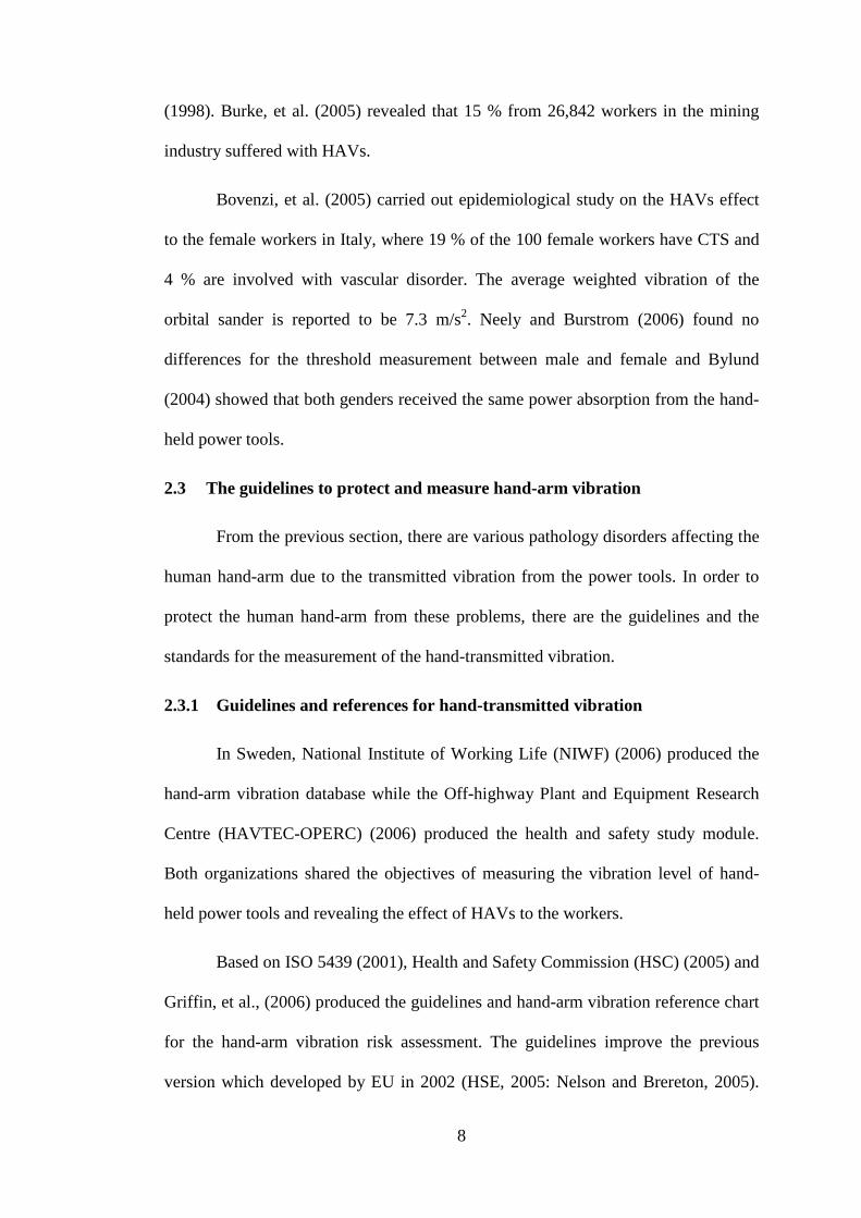
filter (Wh) for this calculation is shown in Figure 2.3.
Figure 2.3: Frequency-weighting filter (Wh) with band limitation for hand-transmitted vibration (ISO 5349-1, 2001)
From Figure 2.3, at low frequencies, the weighted factor is high which can be
considered to be the most harmful. Meanwhile, the frequencies which are out of this
range can be neglected.
In some cases, the estimated total vibration value has to be calculated when
the measurement of the three vibration axes cannot be done simultaneously. This
calculation can be obtained from the second part of ISO 5349 (2001). Moreover, the
ISO 5349-2 (2001) also described the practical measurement guideline such as the
mounting of accelerometers, duration of measurement and the working procedures.
12
2.4 Modeling of hand-held power tools
Oddo, et al., (2004) modeled a suspended handle of the rock drill as a single-
degree-of-freedom (SDOF) system to attenuate the hard-arm vibration. Two types of
suspended handles are modeled; (1) handle with four helicoidally springs and (2)
handle with four viscoelastic mounts. Using the four-pole parameter (Snowdon,
1971), the models are coupled with the four-degree-of-freedom (4DOF) ISO 10068
hand-arm model to observe the effectiveness of the suspended handles.
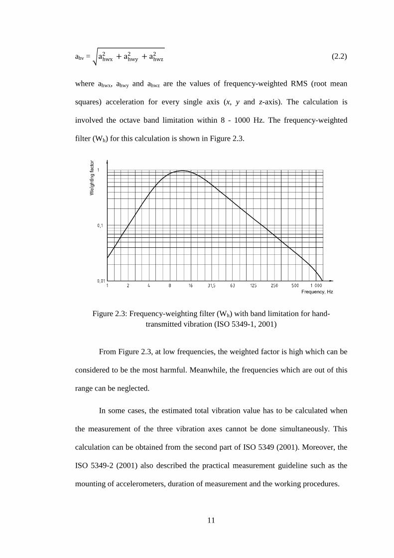
Golysheva, et al., (2004) developed a dynamic model for the electro-
pneumatic hammer consisted of five main parts of the hammer which include the
suspended handle, machine casing, exciting piston, striker and the pick. A SDOF
hand-arm model is coupled with the suspended handle of the hammer and the hand-
arm model parameters are experimentally derived. The details of cross section
diagram and dynamic model of the pneumatic hammer are shown in Figure 2.4. The
figure shows that the combination of vibration isolation and dynamic absorption
principles are used to attenuate the hand-arm vibration for this model.
Figure 2.4: Cross section diagram and dynamic model of pneumatic hammer (Golysheva, et al., 2004)

13
2.5 Human hand-arm biodynamic models
The biodynamic hand-arm model is used to observe the dynamic behavior
and response of the hand-arm system such as motion and force (Dong, et al., 2005).
There are different types of human hand-arm biodynamic models in order to measure
and evaluate the response of the hand-arm system as well as to perform the risk
assessment and the vibration suppression mechanism of the hand-arm system
(Rakheja, et al., 2002).
Basically, human hand-arm biodynamic models are categorized into two
different types which is to-the-hand and through-the-hand biodynamic models. To-
the-hand biodynamic model is usually used to investigate the driving-point
mechanical impedance (DPMI) of the hand-arm system while through-the-hand
model is used to evaluate the transmitted vibration in specific hand-arm segments
(Rakheja, et al., 2002).
2.5.1 To-the-hand biodynamic models
As mentioned previously, the DPMI can be defined as the ratio of the applied
input force F(s) to the resulting velocity X(s) at the hand-handle interface. The
equation of DPMI is given by equation (2.3):
ZD(s) = F(s) / X(s) (2.3)
where (s = jω) is a complex numbers that can be expressed in terms of magnitude
and phase. Rakheja, et al., (2002) carried out a comprehensive literature review on
the biodynamic hand-arm models from single-degree-of-freedom (SDOF) to multi-
degree-of-freedom (MDOF) models, lumped mass approximated models and
distributed parameter models.
14
The first hand-arm beam model is developed by Wood, et al., in 1978. This
model is presented as two long bones of the arm by using distributed mass and
stiffness parameters. The next hand-arm beam model is produced in ISO 10068
(1998). In 1972, the first SDOF hand-arm model is developed by Reynolds and
Soedel covers all three orthogonal axes directions. Miwa, et al. (1979) designed a
higher degree-of-freedom of the hand-arm models including 2DOF and 3DOF of
semi-defined hand-arm models. Rakheja, et al., (2002) reported that some
researchers have developed 3DOF and 4DOF hand-arm models between 1977 to
1998 such as Mishoes and Suggs, (1977), Reynolds and Falkenberg, (1984), Daikoku
and Ishikawa, (1990), Gurram, (1993) and ISO 10068, (1998).
Since the measurement methods are not standardized plus the different
conditions of DPMI measurement (Rakheja, et al., 2002), the result of parameters
obtained for each hand-arm model are significantly different (Gurram, et al., 1995;
Dong, et al., 2005). As a result, most of the biodynamic hand-arm models are not
suitable for the advance modeling of coupled hand-arm with the power tools
(Rakheja, et al., 2002). For example, some of the natural frequencies obtained for the
hand-arm model are significantly low and did not coincided with the formulated
frequency range. Also, there are no specific ranges of frequency for the model
parameters in each axis. These problems mostly occurred for the higher degree of
freedom hand-arm models such as Reynolds and Falkenberg, (1984), Daikoku and
Ishikawa, (1990), Gurram, (1993) and ISO 10068, (1998). There are three models;
Reynolds and Soedel, (1972), Mishoe and Suggs, (1977) and Miwa, et. al. (1979),
which have obtained all the natural frequencies in the range of formulated frequency
and only Reynolds and Soedel specified the range of frequency for each direction of
the hand-arm model parameters.

15
2.5.2 Through-the-hand biodynamic models
Transmissibility principle played a main role in developing through-the-hand
biodynamic model (Rakheja, et al., 2002). Transmissibility T(s) is defined as a ratio
measurement of resulting acceleration X(s), velocity X(s) or displacement X(s) to the
excitation acceleration X 0(s), velocity X 0(s) or displacement X0(s) and can be
calculated using equation (2.4):
T(s) = X(s) / X0(s) = X(s) / X0(s) = X(s) / X0(s) (2.4)
Since the transmitted vibration data is not very satisfactory plus the difficult
process of obtaining the model parameters, the application of through-the-hand
models in determining the biodynamic response of the hand-arm system is unpopular
(Cherian, et al., 1996; Rakheja, et al., 2002).
Cherian, et al., (1996) developed a five-degree-of-freedom (5DOF) hand-arm
model to investigate the transmitted vibration at specific segments of the hand-arm
system. The system consisted of three main parts of the hand, forearm and upper arm.
A 25 N of grip force is applied at the palm of the orbital sander during the
experiment with the frequency range formulated from 10 to 200 Hz. In this study, the
model parameters are obtained from the vibration transmissibility characteristic
result.
2.6 Coupled power tool-hand-arm models
Literatures on the DPMI cover the influence of the grip and push forces,
handle sizes, hand postures and vibration directions of the biodynamic hand-arm
(Aldien, et al., 2005; Marcotte, et al., 2005; Aldien, et al., 2006; Besa, et al., 2007,
Xu, et al., 2011; Adewusi et al., 2012). However, there are only limited studies on

16
the dynamic behavior of coupled power tool-hand-arm model using the DPMI result
of the biodynamic hand-arm model.
An example of the use of the to-the-hand biodynamic model is carried out by
Oddo, et al., (2004), which involved the application of ISO 10068 (4DOF) second
biodynamic hand-arm model coupled with modeled suspended handle of the rock
drill using the four-pole parameters theory. The natural frequency range used for the
drill is between 35 to 45 Hz which is in the range of formulated frequency (10-500
Hz) of the ISO 10068 hand-arm model. For the 50 N push force, the measured and
computed result showed good correlation for the frequency range of 50 - 400 Hz.
This result proves that ISO 10068 hand-arm model is acceptable to be used in the
study.
Ko, (2008) developed coupled orbital sander-hand-arm model by using the
5DOF through-the-hand biodynamic model which have been developed previously
by Cherian, et al., (1996). In this study, the elastomeric pad is used as an intercession
material between the orbital sander and the hand-arm model to attenuate the
vibration transmitted to the hand-arm system. The result shows that the elastomeric
pad is better than flow divider developed by Cherian, et al., in attenuating the
vibration transmitted to the hand-arm system.
2.7 Attenuation of hand-transmitted vibration
There are several ways of reducing the vibration level transmitted to the hand.
The best method is to control vibration from the source which involved the masses
balancing, translating or rotating, clearance minimization and streamlining the
disturbances exposed components (William, 2007). For example, in the commercial

17
hand-held power tool manufacturer, Makita, (2012b) managed to dynamically
balance the motor of the electric jigsaw which resulted in 40 % reduction of vibration.
In addition, redesign the structure of the tool can shift the natural frequency
of the tool away from the operating frequency. As a result, it can reduce the vibration
and avoid the resonance of the structure (William, 2007). For example, Greenslade
and Larsson (1997) redesigned the chainsaw used by the lumberjack. The result
shows that the vibration is reduced by 85 % (Sampson and Niekerk, 2003). Even
though this solution is good, it requires structure redesign and increasing tool
components which contributed to the design complexity and increasing overall cost
of the tools (Golysheva, et al., 2004; Ko, 2008). However, it is depend on how the
components will be designed. As such for the aftermarket demand, the remaining
solution is to go for the vibration isolation approach, vibration absorption approach
and active vibration control technology (Golysheva, et al., 2004; Hassan, et al., 2010).
2.7.1 Vibration isolation approaches
Vibration isolation approach involved the use of isolator which can be placed
between the sources (power tools) and the receivers (human hand). Isolator consisted
of stiffness and damping element which in general is made of rubber, elastomeric
and viscoelastic materials. By using these elements, the transmitted vibration from
the sources to the hand-arm system can be reduced (William, 2007).
A rubber mount is usually used as an isolator for most of the tools since it is
compact, cost effective and maintenance free (Tewari and Dewangan, 2009). Ko, et
al., (2011a) designed three types of suspended handle for the portable petrol grass
trimmer. In these designs, a rubber mount is used as an isolator between the base
plate and the suspended handle. The material of the handles and distance of the
18
rubber mount are different for each type of suspended handle. The result shows that
the handle with heavier material can reduce the transmitted vibration by 76 %. The
study also proved that the distance of rubber mount influenced the reduction of the
vibration.
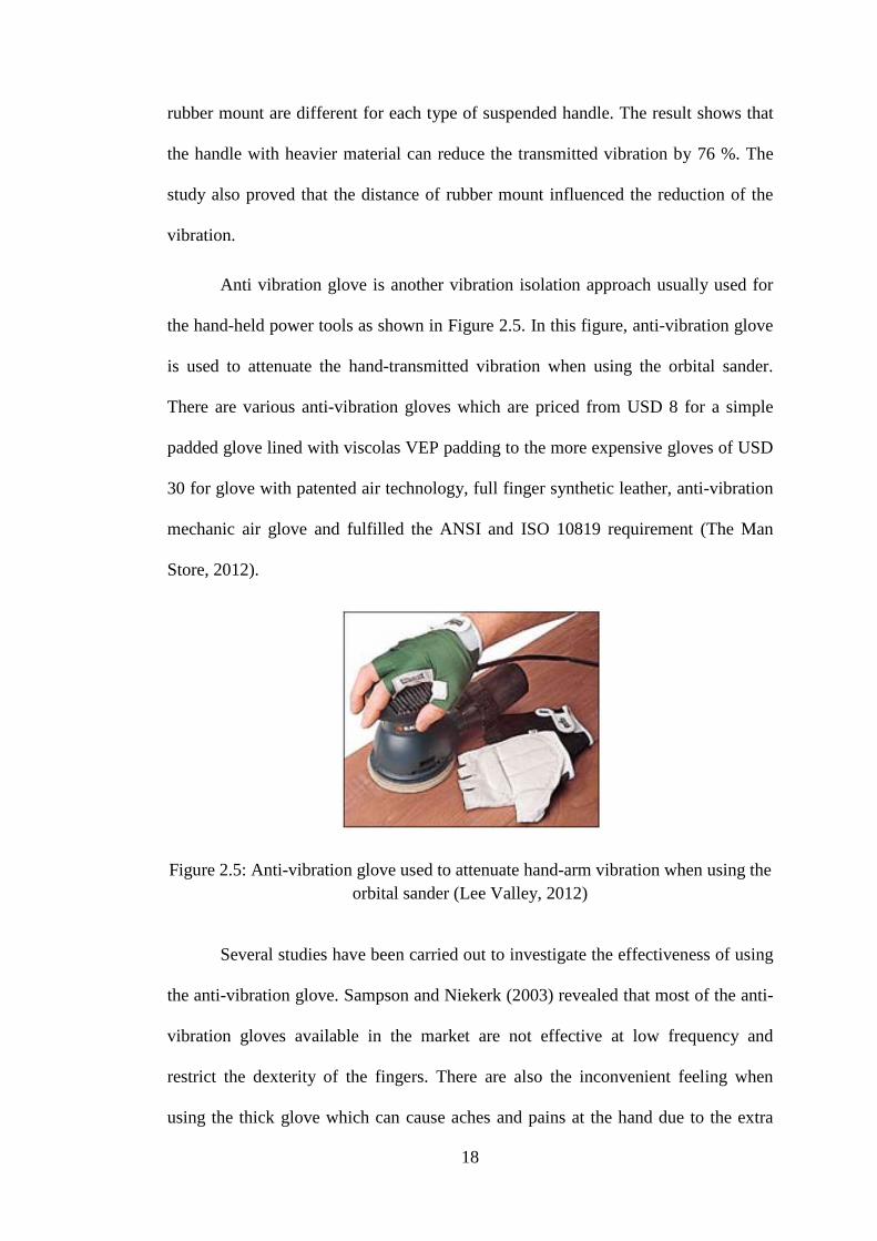
Anti vibration glove is another vibration isolation approach usually used for
the hand-held power tools as shown in Figure 2.5. In this figure, anti-vibration glove
is used to attenuate the hand-transmitted vibration when using the orbital sander.
There are various anti-vibration gloves which are priced from USD 8 for a simple
padded glove lined with viscolas VEP padding to the more expensive gloves of USD
30 for glove with patented air technology, full finger synthetic leather, anti-vibration
mechanic air glove and fulfilled the ANSI and ISO 10819 requirement (The Man
Store, 2012).
Figure 2.5: Anti-vibration glove used to attenuate hand-arm vibration when using the orbital sander (Lee Valley, 2012)
Several studies have been carried out to investigate the effectiveness of using
the anti-vibration glove. Sampson and Niekerk (2003) revealed that most of the anti-
vibration gloves available in the market are not effective at low frequency and
restrict the dexterity of the fingers. There are also the inconvenient feeling when
using the thick glove which can cause aches and pains at the hand due to the extra

19
forces required to hold the tools. Moreover, Dong, et al., (2005) claimed that anti-
vibration glove only reduce the vibration at the handle of the power tools but not on
the fingers.
For the power tools such as angle grinders, Bosch has developed anti-
vibration handle which is priced at USD 24 (Toolnweld, 2006). The anti-vibration
handle works on the isolation effect when damping element is inserted between the
handle and the motor housing with the damping element frequency characteristics
tuned to match the characteristics of the motor. The magnitude of isolation has
achieved however is not mentioned. An almost similar design is developed by
Makita, (2012a) for angle grinder which is called anti-vibration side handle as shown
in Figure 2.6. In this figure, the handle works on the basis of isolation where the
elastomeric components (rubber damper) are inserted to isolate the handle from the
vibration of the body of the power tools.
Figure 2.6: Anti-vibration side handle (Makita, 2012a)
2.7.2 Vibration absorption approaches
The vibration of power tools can be reduced by attaching a secondary mass or
in some cases with a stiffness elements at the source or receiver of the power tools
such as dynamic vibration absorber (DVA) (Golysheva, et al., 2004; Ko, et al.,
2011b). The natural frequency of DVA is tuned to match the natural frequency of the
20
main mass. As a result, the energy of the main mass will be absorbed by the DVA
and the motion at the natural frequency of the main mass can be reduced to zero
(William, 2007).
Ko, et al., (2011b) designed a tuned vibration absorber (TVA) and attached to
the electric grass trimmer to reduce the hand-transmitted vibration. The TVA is
attached at the various shaft location of the grass trimmer. The experiment is carried
out in two field conditions for cutting and no cutting operations. The result shows
that the vibration at the handle of the grass trimmer is significantly reduced in z-axis
direction for both conditions. Also, the TVA produced the best performance by
reducing the vibration by 95 % for the grass trimmer. The same concept has been
applied before by Strydom (2000), where the DVA is attached to the handle of rock
drill and the result shows that the vibration reduced by 40 %.
One approach of applying the dynamic vibration absorber on the receiver is
done by Cherian, et al, (1996) which is named as flow divider. The flow divider is
attached to the five-degree-of-freedom (5DOF) of hand-arm model consisted of the
hand, forearm and upper arm. The result shows that the vibration level at the hand is
reduced to 5.3 m/s2 from the original weighted acceleration of 6.8 m/s2. However,
due to the characteristic of the DVA, the vibration level at the upper arm and forearm
has increased by 10 % and 13 % respectively. Rade and Steffen, (2002) revealed that
the vibration level at certain points can be increased or decreased depend on the
DVA characteristic.
2.7.3 Active vibration control (AVC) approaches
For cases where the disturbances and frequencies of the dynamic system are
changing with time, passive control becomes ineffective. Due to this condition, an

21
active vibration control (AVC) is introduced to the system (William, 2007; Hassan,
et al., 2010). Figure 2.7 shows the basic control diagram of the AVC system. In this
figure, the AVC system consisted of sensor to measure the feedback signal of the
system (process) and a set of control system to process the feedback signal and
computed the difference signal for the actuator to counteract the forces produced by
the system (Mohamad, 2004; William, 2007). Basically, the actuator such as
piezoelectric, electric motor and hydraulic cylinder are used in the AVC system
(William, 2007).
Figure 2.7: Basic control diagram for AVC system (Stienecker, 2011)
There are many controller techniques that can be applied in the AVC system.
One of the techniques which has been widely used in the AVC field is the
proportional-integral-derivative (PID) (Yildrim, 2004; Hassan, et al., 2010). The
theory and details of PID technique are discussed later in Chapter Three
(Methodology).
There are many applications of using PID controller in the experiment as well
as in simulation works. For example, Trojanowski and Wiciak, (2009) applied the
PID controller scheme to suppress the vibration of the aluminium plate. In this
experiment, the plate is clamped in one side with the other side is freely vibrated.
Five piezoelectric elements are introduced to the plate with four of them functioned
22
as a sensor and actuator. Meanwhile, another one is used to produce an excitation for
the plate. The result shows that the piezo actuator can suppress 22.5% to 25% of
vibration for both measured locations.
A similar study is carried out by Knot, et al., (2011) which involved
simulation using PID technique as a controller for the cantilever beam and
piezoelectric elements as the sensor and actuator. The cantilever beam is modeled in
the finite element (FE) environment (Ansys) and then constructed in the Simulink
software for the AVC simulation. Two types of models are designed which is named
as full and reduced models. The result shows that both models have achieved the
reduction of the vibration of the cantilever beam.
The application of PID controller at the plate is extended by Rahman, et al.,
(2011). The study is focused on using one of the PID control elements which is
proportional (P) gain. The P gain is used as a controller parameter to suppress the
vibration of the flexible plate. In this experiment, piezoelectric patch is used as an
actuator for the AVC system. The first five natural frequencies of the plate are
defined and the result shows that the P gain controller has reduced most plate energy
at the fourth natural frequency with 15.5 % of vibration reduction.
Apart from PID controller, there are many types of controller techniques
which can be applied in the AVC field such as neural network (NN) (Yildrim, 2004),
fuzzy logic (FL) (Li, et al., 2009; Ahmad, et al., 2010), genetic algorithm (GA)
(Bruant, et al., 2010), Linear Quadratic Gaussian (LQG) (Chen, et al., 2003;
Waghulde, et al., 2010) and etc. In the commercial hand-held power tool
manufacturer, Bosch, (2012) claimed that AVC has been successfully implemented
in their rotary hammer drill product. However, the design of the AVC system and the
magnitude of vibration reduction are not mentioned.

23
2.7.3.1 Active Force Control (AFC) technique
One of the most efficient control technique in the AVC field is called active
force control (AFC). AFC is firstly introduced in 1981 by Hewit and Burdess. After
that, many researchers have applied the AFC technique in their application and the
results proved that the technique is effective for the AVC system even though in the
influence of known or unknown disturbances (Mailah, et al., 2009; Hassan, et al.,
2010). The discussion of theory and the detailed process of AFC control technique
are covered in Chapter Three (Methodology).
Kwek, et al., (2003) applied the AFC technique to control the five-link biped
robot. The robot is tested for the biped walk on the horizontal flat surface and the
locomotion is set to be constrained within the sagittal plane. Three types of control
schemes are applied which include the PD, AFC with crude approximation (AFC-
CA) and AFC with iterative learning method (AFC-ILM). The results show that both
AFC schemes produced a superior result than PD scheme even though under the
presence of disturbances.
Varatharajoo, et al., (2011) incorporated the AFC technique in two-degree-of-
freedom (2DOF) spacecraft attitude controller. Two types of controllers are
introduced to the system which is PD and PD+AFC techniques. The numerical
analysis is performed and the best result is obtained by PD+AFC controller. The
AFC technique also improved the accuracy of attitude pointing of the Combined
Energy and Attitude Control System (CEACS).
There are very limited literatures on the application of AFC technique for the
hand-held power tools. Hassan, et al., (2010) applied the AFC control technique to
suppress the vibration at the rear handle of hedge trimmer. The simulation consisted

24
of applying four types of controllers which is PID, AFC with crude approximation
(AFC-CA), AFC with fuzzy logic (AFC-FL) and AFC with iterative learning method
(AFC-ILM). The external disturbance is introduced to the system and the
performances of the controllers are compared. The result proved that all three types
of AFC schemes produced a better result compared to PID controller with the AFC-
FL scheme gives the best performance.
One approach of applying the AFC technique on the receiver is carried out by
Mailah, et al., (2009). The AFC controller is constructed and linked with the model
of two-link planar mechanical manipulator that represented a human arm. An
excitation is applied to the certain point of the human arm model to evaluate the
effect when performing trajectory tracking task in two dimensional spaces. The result
shows that AFC scheme is better than PD scheme in suppressing the vibration and
can produce an accurate tracking performance for the system.
2.8 Discussion
From the literatures, it is realized that prolonged exposure to the hand-
transmitted vibration from the power tools can result of hand-arm vibration
syndrome (HAVs) which is the combination of vascular and non-vascular disorder
(Brammer, et al., 1987; Griffin, 1990; Bovenzi, 1998; Fridén, 2001; Stoyneva, et al.,
2003; HSC, 2005; Mansfield, 2005; Griffin, et al., 2006). Epidemiology studies have
come out with a statistical data to prove that the power tools can contribute to the
HAVs (Niekerk, et al., 1998; Sampson and Niekerk, 2003; Bylund, 2004; European
Communities, 2004; Bovenzi, et al., 2005; Burke, et al., 2005; Neely and Burstrom,
2006; Nyantumbu, et al., 2007; Vergara, et al., 2008).