Active Passive Beams Engineering Guide - Price Industries
48
Please refer to the Price Engineer’s HVAC Handbook for more information on Active & Passive Beams. SECTION L Engineering Guide Active & Passive Beams
Transcript of Active Passive Beams Engineering Guide - Price Industries

Please refer to the Price Engineer’s HVAC Handbook for more information on Active & Passive Beams.
S E C T I O N L
Engineering GuideActive & Passive Beams

All Metric dimensions ( ) are soft conversion. © Copyright Price Industries Limited 2011. Imperial dimensions are converted to metric and rounded to the nearest millimeter. L-2L-2 All Metric dimensions ( ) are soft conversion. © Copyright Price Industries Limited 2011. Imperial dimensions are converted to metric and rounded to the nearest millimeter.
EN
GIN
EE
RIN
G G
UID
E -
AC
TIV
E &
PA
SS
IVE
BE
AM
S
Introduction
Active&PassiveBeamsEngineering Guide
Likeradiantheatingandcoolingsystems,activeandpassivebeamsystemsusewateraswellasairtotransportenergythroughoutthe building. Like radiant and coolingsystems,theyoffersavingsinenergy,spaceand maintenance costs. Unlike radiantheating and cooling systems, however,these technologies deliver the majorityof their cooling and heating throughconvection,oftenleadingtoafullymixedenvironment.Thissectionintroducesactiveandpassivebeamsystemsandtheirdesignconsiderations,andaddressestheuniquerequirementsofsomeofthemostcommonapplications.
Managementofheat loadscangenerallybeclassifiedintotwodifferent types:all-
air systems or hybrid systems. All-airsystems have been themost prominentinNorthAmericaduringthe20thcenturyandhavebeeninusesincetheadventofairconditioning.Thesesystemsuseairtoservice both the ventilation requirementaswell as thebuilding cooling loads. Ingeneral,thesesystemshaveacentralairhandling unit that delivers enough coolorwarmair to satisfy thebuilding load.Diffusersmountedinthezonedeliverthisair insuchawayas topromotecomfortandevenlydistributetheair.Inmanycases,theamountofairrequiredtocoolorwarmthespaceorthefluctuationsofloadsmakedesigninginaccordancetotheseprinciplesdifficult.
Hybrid systems combine an air-sideventilationsystemandahydronic(orwater-side)system.Theair-sidesystemisdesignedtomeetalloftheventilationrequirementsforthebuildingaswellassatisfythelatentloads. It is typically a 100% outside airsystemandbecausetheprimaryfunctionofthesupplyairsystemisventilationanddehumidificationasopposed tosensiblecoolingitcanbesuppliedathighersupplyairtemperaturesthanistypicaloftraditionalmixingairdistributionsystems.Thewater-sidesystemisdesignedtomeetthebalanceofthesensiblecoolingandheatingloads.These loadsarehandledbywater-basedproducts,suchasactiveandpassivebeams,which transfer heat to the zone by induction.

© Copyright Price Industries Limited 2011. All Metric dimensions ( ) are soft conversion. Imperial dimensions are converted to metric and rounded to the nearest millimeter. L-3
Active & Passive BeamsEngineering Guide
© Copyright Price Industries Limited 2011. All Metric dimensions ( ) are soft conversion. Imperial dimensions are converted to metric and rounded to the nearest millimeter. L-3
EN
GIN
EE
RIN
G G
UID
E -
AC
TIV
E &
PA
SS
IVE
BE
AM
S
Concepts and Benefits
Activeandpassivebeamsystemsprovideaneffectivemethodforprovidingheatingorcooling toaspacewhilepromotingahighlevelofoccupantcomfortandenergyefficiency.There are two distinct systemdesign philosophies that are consideredwhen applying hydronic heating and/orcooling:
Hydronic heating or cooling where thehydronicsystemsareintegratedwiththeprimaryventilationsystem.Theseareactivebeam systems (Figure 1).Hybridheatingorcoolingsystemswherewater-baseddevicesareusedinconjunctionwithascaled-downventilationsystem,andmanage thebulkof the sensible coolingload.Thesesystemsgenerallyusepassivebeams (Figure 2). Hydronicsystemshavebeensuccessfullyused in several applications havingdramatically different characteristics. Some examplesofareaswhereactiveandpassivebeamsystemshavebeenappliedinclude:
• GreenBuildings• PostSecondaryEducationalFacilities• LoadDrivenLaboratories• K-12Schools• OfficeBuildings• Cafeterias• TelevisionStudios
Benefits of Air-Water SystemsThere aremany benefits to heating andcooling using active or passive beams.Advantages of water-based heating andcooling systems over other mechanicalsystemsinclude:
• Energyandsystemefficiency• Reducedsystemhorsepower• Improvedindoorenvironmentalquality• Improvedindoorairquality• Increasedthermalcomfort• Reducedmechanicalfootprint• Lowermaintenancecosts• ImprovedsystemhygieneActiveorpassivebeamsystemsareagoodchoicewhere:
• Thermal comfort is a major designconsideration
• Areaswithhighsensibleloadsexist/arepresent
• Areas requiring a high indoor air quality(100%outdoorairsystem)exist/arepresent
• Energyconservationisdesired
Energy EfficiencyTheheattransfercapacityofwaterallowsforareductionintheenergyusedtotransportanequivalentamountofheatasanall-airsystem(Stetiu,1998).Thesereductionscanbefoundprimarilythroughreducedfanenergy.
Figure 1: Airflowdiagramofatypicallinearactivebeamincooling
Figure 2:Air flow diagramof a passivechilledincooling
Figure 3: Activebeamsinstalled inanoffice
Figure 4: Passivebeamsbehind aperforatedceiling
Nozzles
Plenum
Primary Air
Room Air
Coil
Room Air
Primary Air
Thehigher chilledwater supply (CHWS)temperaturesusedwithactiveandpassivebeam systems, typically around 58 °F[14.5°C],providemanyopportunitiesforareductioninenergyuse,includingincreasedwater-sideeconomizeruse.ThisincreasedCHWStemperaturealsoallows formorewet-sideeconomizerhoursthanwouldbepossiblewithothersystemswhereCHWStemperaturesaretypically~45°F[7°C].
Indoor Air QualityDepending on the application, undermaximum load, only ~15 to 40% of thecoolingairflowinatypicalspaceisoutdoorairrequiredbycodetosatisfytheventilationrequirements.Thebalanceof the supplyairflowisrecirculatedairwhich,whennottreated,cantransportpollutantsthroughthebuilding.Activeandpassivebeamsystemstransferheatdirectlyto/fromthezoneandare often usedwith a 100% outdoor airsystemthatexhaustspollutedairdirectlyto the outside, reducing the opportunityforVOCsandillnesstotravelbetweenairdistribution zones.
NoiseActiveandpassivebeamsystemsdonotusuallyhavefanpowereddevicesnearthezone.Thistypicallyresultsinlowerzone
noiselevelsthanwhatisachievedwithall-airsystems. Insituationswherepassivebeams are used in conjunction with a quiet air system, such as displacementventilation, the opportunities for noisereduction increase further.
Reduced Mechanical FootprintThe increased cooling capacity ofwaterallowsthetransportsystemtobereducedinsize.Generally,itisnotunusualtobeabletoreplace~60ft²[6m²]ofairshaftwitha6in.[150mm]waterriser,increasingtheamountoffloorspaceavailableforuseorlease.Duetothesimplicityofthesystems(i.e.reductioninthenumberofmovingpartsand theeliminationof zonefilters,drainpans,condensatepumpsandmechanicalcomponents),theretendstobelessspacerequiredintheinterstitialspacetosupporttheHVACsystem.
Lower Maintenance CostsWithnoterminalunitorfancoilfiltersformotors to replace,asimpleperiodiccoilcleaningisallthatisrequiredinordertomaintaintheproduct.

All Metric dimensions ( ) are soft conversion. © Copyright Price Industries Limited 2011. Imperial dimensions are converted to metric and rounded to the nearest millimeter. L-4
Active & Passive BeamsEngineering Guide
L-4 All Metric dimensions ( ) are soft conversion. © Copyright Price Industries Limited 2011. Imperial dimensions are converted to metric and rounded to the nearest millimeter.
EN
GIN
EE
RIN
G G
UID
E -
AC
TIV
E &
PA
SS
IVE
BE
AM
S
When to use Beam Systems
ApplicationTotal Air
Volume (Typ.)Ventilation Requirement
(Typ.)Air-Side
Load Fraction
Office 1cfm/ft2 [5L/sm2] 0.15cfm/ft2 [0.75L/sm2] 0.15
School 1.5cfm/ft2 [7.5L/sm2] 0.5cfm/ft2 [2.5L/sm2] 0.33
Lobby 2cfm/ft2 [10L/sm2] 1cfm/ft2 [5L/sm2] 0.5
PatientRoom 6 ach 2 ach 0.33
Load-drivenLab 20 ach 6 ach 0.3
Hygienic SystemWith the elimination of the majority of filtersanddrainpans, there isareducedriskofmoldorbacteriagrowthintheentiremechanical system.
Activeandpassivebeamsystemsarewell-suitedtosomeapplicationsandlesssotoothers.Asaresult,eachapplicationmustbereviewedforpotentialbenefitsaswellasthesuitabilityofthesetypesofsystems.Oneconsiderationwhichcanassistinthedecision to employhydronic systemsasopposedtoanall-airsystemistheair-sideloadfraction,orthepercentageofthetotalairsupplywhichmustbedeliveredtothezonetosatisfycodeanddehumidificationrequirements. Table 1 shows the load fractionforseveralspaces.Inthetablethebestapplicationsforhydronicsystemsarethosewiththelowestair-sideloadfractionastheyaretheonesthatwillbenefitthemostfromtheefficienciesofhydronicsystems.Anotherfactorwhichshouldbeexaminedisthesensibleheatratioorthepercentageof the cooling loadwhich is sensible asopposedtolatent.Thelatentloadsmustbesatisfiedwithanairsystemandoffersomesensiblecoolingatthesametimeduetothetemperatureofdehumidifiedair.Ifthetotalsensiblecoolingloadissignificantlyhigherthanthecapacityoftheairsuppliedto satisfy the latent loads, a beam system mightbeagoodchoice.
Commercial Office BuildingsIn an office building, active and passivebeamsystemsprovideseveralbenefits.Thelowersupplyairvolumeoftheairhandlingsystemprovidessignificantenergysavings.In addition, the smaller infrastructurerequiredtomovethislowerairflowallowsforsmallplenumspaces,translatingintoshorterfloor-to-floorconstructionorhigherceilings.Thelowersupplyairvolumeandelimination of fans at or near the spaceoffersasignificantreductioningeneratednoise.Thelowerairflowoftentranslatestoreheatrequirementsbeingreduced.Inthecaseof100%outsideairsystems,thelightingloadcapturedinthereturnplenumisexhaustedfromthebuilding,loweringtheoverallcoolingload.
SchoolsSchoolsareanotherapplication that canbenefitgreatlyfromactiveandpassivebeamsystems. Similar toofficebuildings, thebenefitsofalowersupplyairvolumetothespacearelowerfanpower,shorterplenumheight,reducedreheatrequirementsandlowernoiselevels(oftenacriticaldesignparameterofschools).
Hospital Patient Rooms
Hospitalsareuniqueapplications in thatthe supply air volume required by localcodesforeachspaceisoftengreaterthantherequirementofthecoolingandheatingload. In some jurisdictions, local coderequiresthesehigherair-changeratesforall-air systemsonly. In these cases, thetotalair-changeraterequiredisreducedifsupplementalheatingorcoolingisused.This allows for a significant reductionin system air volume and yields energysavingsandotherbenefits.
Furthermore,because thesesystemsaregenerally constant air volume with thepotentialtoreducetheprimaryair-changerates, reheat and the cooling energydiscardedaspartofthereheatprocessisasignificantenergysavingsopportunity.Depending on the application, a 100%outside air system may be used. These systems utilize no return air and therefore nomixing of return air between patientroomsoccurs,potentiallyloweringtheriskofhospitalassociatedinfections.
LaboratoriesInloaddrivenlaboratorieswherethesupplyairrateisdrivenbytheinternalgains(suchas refrigerators, testing equipment, etc.)asopposedtotheexhaustrequirements,active and passive beam systems canoffersignificantenergysavings.Intheseenvironmentsit isnotunusualtorequirea largeair-changerate inordertosatisfythe load,althoughsignificantly lessmayberequiredbycode(ASHRAE,2008;CSA,2010).
Table 1: TypicalloadfractionsforseveralspacesintheUnitedStates
Intheseapplications,thedifferencebetweenthesupplyairvolumerequiredtomanagethe sensible loads and that required tomeetthefumehoodairflowrequirementsprovides opportunity for energy savingsthroughtheapplicationofactiveandpassivebeams.Thesesavingsaretypicallyduetothereductioninfanpoweraswellastheenergyassociatedwithtreatingtheoutsideair,which,inthecaseofaloaddrivenlab,maybesignificant.
Hotels / Dorms Hotels,motels,dormitoriesandsimilartypebuildingscanalsobenefitfromactiveandpassivebeamsystems.Fanpowersavingsoften come from the elimination of fan coil units located in theoccupied space.Theenergysavingsassociatedwiththese“local”fansissimilarinmagnitudetothatoflargerairhandlingsystems.Italsoallowsfortheeliminationoftheelectricalservicerequiredfortheinstallationoffancoilunits,as well as a reduction in the maintenance ofthedrainandfiltersystems.Theremovalofthesefansfromtheoccupiedspacealsoprovideslowernoiselevels,whichcanbeasignificantbenefitinsleepareas.
LimitationsThereareseveralareasinabuildingwherehumiditycanbedifficult tocontrol,suchas lobby areas and locations of egress.These areasmay see a significant shortterm humidity load if the entrances are not isolatedinsomeway(revolvingdoorsorvestibules). Intheseareas,achoiceofacomplimentarytechnologysuchasfancoilunitsordisplacementventilationisideal.
Other applications may have high airflow/ventilationrequirements,suchasanexhaust driven lab. Themajority of thebenefitprovidedbythehydronicsystemislinkedtothereductioninsupplyairflow.Assuch, theseapplicationsmaynot seesufficientbenefittojustifytheadditionofthehydroniccirculationsystems,makingthemnotlikelytobeagoodcandidateforthistechnology.

© Copyright Price Industries Limited 2011. All Metric dimensions ( ) are soft conversion. Imperial dimensions are converted to metric and rounded to the nearest millimeter. L-5
Active & Passive BeamsEngineering Guide
© Copyright Price Industries Limited 2011. All Metric dimensions ( ) are soft conversion. Imperial dimensions are converted to metric and rounded to the nearest millimeter. L-5
EN
GIN
EE
RIN
G G
UID
E -
AC
TIV
E &
PA
SS
IVE
BE
AM
S
Passive Beams
Passive Beams Passive beams use a heat exchanger–usuallyacoil–tochangethetemperatureoftheadjacenttransferringheatandcreateadifference in density with the ambient air. Thedensitydifferencecreatesairmovementacrosstheheatexchanger,transferringheatfromtheheatexchangertotheair.
Passive beams condition a space usingnaturalconvectionandareprimarilyusedforhandlingthesensiblecoolingloadofaspace.Theyarewater-onlyproducts,andrequireaseparateairsystemforventilationair and to remove the latent load. Aswarm air in the room rises, it comes into contactwiththeheatexchangerandflowsdownwardthroughthecoolcoilsbackintothespace,asseeninFigure 5.Inheatingmode, passive beams are generally notused, though in some special instancestheywouldconditionthespaceprimarilyby thermal radiation.
Product DescriptionPassivebeamsareavailableinmodelsthateither integrate intostandardsuspendedceiling systems or are suspended freelyfromtheceiling.Theyarealsocommonlyinstalledbehindperforatedmetalceilingsforauniformarchitecturalappearance.Aperforatedmetalceilinghelpsreducedraftunderthebeam,however,aminimumfreeareaof50%isoftenrequiredtoensurethecapacityofthebeamisnotreduced.PassivebeamsinstalledbehindametalperforatedceilingcanbeseeninFigure 7.
ComponentsThebasiccomponentsofpassivebeamsinclude a heat exchanger, comprisingofextrudedaluminumfinsandcoppertubing,commonlytermedthe‘coil’,andaframeorshroud.Thesecomponentsareillustratedin Figure 8.
LocationPassivebeamsare ideallysuited toaislewaysorperimetersof largespacessuchas offices, lobbies, conference centers, libraries,oranyotherspacethatrequiresperimeteroradditionalcooling.Airflowfromapassivebeamisstraightdownsotheyarenottypicallyplacedabovewhereanoccupantwillbestationedforanextendedperiodoftime.Whilethevelocityfromapassivebeamislow,thereistheopportunityfor some people in this condition to beuncomfortable.
Figure 6:Airflowdiagramofapassivebeamincooling
Figure 5: Roomairflowpatternofapassivebeamincooling
Coil
Room Air
Primary Air
Figure 7:Passivebeamsinstalledbehindametalperforatedceiling
Face
Figure 8: Componentsofatypicalpassivechilledbeam
Frame/Shroud
Coil

All Metric dimensions ( ) are soft conversion. © Copyright Price Industries Limited 2011. Imperial dimensions are converted to metric and rounded to the nearest millimeter. L-6
Active & Passive BeamsEngineering Guide
L-6 All Metric dimensions ( ) are soft conversion. © Copyright Price Industries Limited 2011. Imperial dimensions are converted to metric and rounded to the nearest millimeter.
EN
GIN
EE
RIN
G G
UID
E -
AC
TIV
E &
PA
SS
IVE
BE
AM
S
NozzlesPrimary Air
Room Air
Nozzles
Plenum
Primary Air
Room Air
Figure 10: Airflowdiagramofatypicallinearactivebeamincooling
Figure 11:Air flowdiagramof a typicallinearactivebeaminheating
Active Beams
Plenum
MountingBracket
Primary Air Inlet
Operable Face to allow access to the coil
Coil
Figure 12: Componentsofatypicallinearactivebeam
Figure 9:Roomairflowpatternofatypicallinearactivebeamincooling
Active BeamsActivebeamsuse theventilationsystemto increasetheoutputof thecoil,andtohandle both latent and sensible loads of a space. Unlike radiantpanelsandchilledsails, which rely primarily on thermalradiationtoconditionaspace,activebeamsheat or cool a space through inductionand forced convection. An active beamacceptsdryairfromthesystemthroughapressurizedplenum.Thisprimarysupplyairisthenforcedthroughnozzlesinordertocreateahighvelocityairpatternintheareaadjacenttothecoil.Thishighvelocitycauses a reduction in the local static pressure, inducing roomair through theheating/coolingcoil.Theinducedairthenmixeswiththeprimarysupplyairand isdischarged back into the space via slotsalongthebeam (Figure 9).AtypicalairflowdiagramofalinearactivebeamincoolingandheatingmodescanbeseeninFigure 10, and Figure 11respectively.ComponentsThe basic components of active beamsincludeaheatexchangerwithaluminumfinsandcoppertubing,commonlytermedthe‘coil,’aplenumboxwithat leastonesupplyinlet,internalnozzles,avisibleface,andaframe.Althoughtheconfigurationsofactivebeamsdiffer,allgeneralcomponentsremainthesame.Thesecomponentsareillustrated in Figures 12.
ApplicationsActive beams can be used in offices,meeting rooms, schools, laboratories,hospitals,datacenters,airports,any‘green’buildingapplication,andlargeareassuchaslobbies, conference facilities, lecture halls or cafeterias.
Twobasictypesofactivebeamsare:
• LinearActiveBeams• ModularActiveBeams
Linear Active Beams2 Way DischargeLinear active beams with two-sideddischargearedesignedtoeitherintegrateintostandardsuspendedceilingsystemsor be suspended freely in an ‘exposed’application.Thesebeamshavetwolinearairslotsthatrunthelengthofthebeam,one on either side.

© Copyright Price Industries Limited 2011. All Metric dimensions ( ) are soft conversion. Imperial dimensions are converted to metric and rounded to the nearest millimeter. L-7
Active & Passive BeamsEngineering Guide
© Copyright Price Industries Limited 2011. All Metric dimensions ( ) are soft conversion. Imperial dimensions are converted to metric and rounded to the nearest millimeter. L-7
EN
GIN
EE
RIN
G G
UID
E -
AC
TIV
E &
PA
SS
IVE
BE
AM
S
Primary Air
Room Air
Room Air
Nozzles
Primary Air
Primary Air
Room Air
Room Air
NozzlesPlenum
Primary Air
Active Beams
Figure 13: Airflowdiagramof a linearactivebeamincoolingwith1waydischarge
Figure 14:Air flowdiagramof a linearactivebeaminheatingwith1waydischarge
Figure 15:Roomairflowpatternofatypicallinearactivebeamincooling
Figure 16: Airflowdiagramofa modularbeamincooling
Figure 17: Airflowdiagramofa modularbeaminheating
1 Way DischargeLinearactivebeamswithsingle-sidedairdischargearedesignedtoeitherintegrateintostandardsuspendedceilingsystemsor be suspended freely in an ‘exposed’application. Thesebeamshaveonlyonedischargeairslotthatrunsalongonesideof the beam.
Thegeneralairflowoflinearactivebeamswith1wayairdistributionincoolingandheatingareseeninFigures 13 and Figure 14. Figure 15illustratestheroomairflowofatypical1wayactivebeam.
PRODUCT TIPLinear active beams with 1 wayair distribution are best suited for placementalongafaçadeorwall.Inapplicationswhere1waybeamsare used with 2 way beams, a symmetric face may be selected for the1wayunittoensureaconsistentappearancefromtheroom.
PRODUCT TIPActivebeamsaretypicallyavailableina2pipeor4pipeconfiguration.Beamswith2pipeconfigurationshave one supply and one returnpipe for each unit, which servesforeither/bothheatingandcoolingpurposes. Beams with 4 pipeconfigurations have two supplyandtworeturnpipesforeachunit,comprising separate loops forcoolingandheating.
Modular Active BeamsModularactivebeamscombine freshairventilation,hydronicheatingandcooling,andfour-sidedairflow.Theyaretypicallyavailableinmodularsizes,2ftx2ft[600mmx600mm],and2ftx4ft[600mmx1200mm], andare available inmodels eitherdesignedtointegrateintostandardceilingtilesorsuspendfreelyfromtheceiling.
Thetypicalairflowpatternofamodularbeamincoolingandheatingisillustratedin Figure 16 and Figure 17.Often,thesemodular beams can be customized to individuallymodulatetheairflowfromeachsideoftheunit.Forexample,onesideoftheunitcanbeblankedofftocreateamodularbeamwiththree-sidedairflow.
Beam Return

All Metric dimensions ( ) are soft conversion. © Copyright Price Industries Limited 2011. Imperial dimensions are converted to metric and rounded to the nearest millimeter. L-8
Active & Passive BeamsEngineering Guide
L-8 All Metric dimensions ( ) are soft conversion. © Copyright Price Industries Limited 2011. Imperial dimensions are converted to metric and rounded to the nearest millimeter.
EN
GIN
EE
RIN
G G
UID
E -
AC
TIV
E &
PA
SS
IVE
BE
AM
S
Passive beam systems will vary inperformance, configuration and layoutdependingontheapplication.Thereare,however, some characteristics that arecommonformostsystems.Furthermore,theperformanceofpassivebeamsislargelydependent on a common set of factors.This section will discuss how factors such as chilledwater temperature affectthe performance and layout of passivebeams. Table 2showscommondesigncharacteristicsforpassivebeamsystems.
Product Selection and Location – Passive BeamsPerformanceThe performance of a passive beam isdependentonseveralfactors:
• Waterflowrate• Meanwatertemperatureand
surroundingairtemperature• Shroudheight• Freeareaoftheairpaths(internaland
externaltothebeam)• LocationandapplicationThewaterflowrateinthecoilaffectstwoperformance factors: the heat transferbetween the water and the coil, which is dependent on whether the flow islaminar(poor)orturbulent(good);andthemeanwater temperature,or theaveragetemperature,inthecoil.Thehighertheflowrate,thecloserthedischargetemperaturewillbetothe inlet, therebychangingtheaverage water temperature in the coil.Figure 18 shows the effect of the flowrate, indicated by Reynolds number, onthecapacityofatypicalpassivebeam.Asindicatedonthechart,increasingtheflowrate into the transitional and turbulent ranges (Re>2300, shaded in thegraph)causes an increase in the output of thebeam.
Thewaterflowrate is largelydependenton the pressure drop and return watertemperatures that are acceptable to thedesigner. Inmost cases, thewaterflowrate should be selected to be fully turbulent underdesignconditions.
The difference between the mean water temperature, t̅w,definedas:
and the surrounding (coil inlet) airtemperatureisoneoftheprimarydriversofthebeamperformance.Thelargerthisdifferenceis,thehighertheconvectiveheattransfer potential. Conversely, a lowertemperature difference will reduce theamountofpotentialenergyexchange,andtherebycapacity.Asaresult,itisdesirablefromacapacitystandpointtoselectentrywater temperatures as low as possible,
Passive Beam Selection and Design Procedure
Table 2: DesignValuesforpassivebeamsystems
IP
RoomTemperature 74°Fto78°Finsummer,68°Fto72°Finwinter
WaterTemperatures,Cooling 55°Fto58°FEWT,5°Fto8°F T
DesignSoundLevels <40NC
CoolingCapacity Upto500Btu/hft
VentilationRequirement 0.1to0.5cfm/ft2floorarea
SI
RoomTemperature 23°Cto25°Cinsummer,20°Cto22°Cinwinter
WaterTemperatures,Cooling 13°Cto15°CEWT,3Kto5K T
DesignSoundLevels <40NC
CoolingCapacity Upto500W/m
VentilationRequirement 0.5to2.5L/sm2floorarea
Figure 18: Passivebeamcapacityvs.waterflow
400 2000 4000 6000 8000 10000 12000
50
60
70
80
90
100
Cap
acity
, %
Re
Figure 19:Passivebeamcapacityvs.differencebetweenmeanwaterandroomairtemperature
00 5 10 15 20
0 2 4 6 8 10
20
40
60
80
100
120
Cap
acity
, %
tw - troom ,˚F
tw - troom ,K

© Copyright Price Industries Limited 2011. All Metric dimensions ( ) are soft conversion. Imperial dimensions are converted to metric and rounded to the nearest millimeter. L-9
Active & Passive BeamsEngineering Guide
© Copyright Price Industries Limited 2011. All Metric dimensions ( ) are soft conversion. Imperial dimensions are converted to metric and rounded to the nearest millimeter. L-9
EN
GIN
EE
RIN
G G
UID
E -
AC
TIV
E &
PA
SS
IVE
BE
AM
S
whilemaintainingitabovethedewpointintheroomtoensuresensiblecoolingonly.
Insomeinstances,itmightbeadvantageousto the designer to use higher watertemperatures,whereitmakessensefromanequipmentstandpoint. Thismayalsooffersomecontrolsimplificationwheretheoutputofthebeamisdeterminedbytheloadintheroom:
• Astheloadincreases,theairtemperaturerises and increases the difference between it and tw, thereby increasingbeamperformance.
• Astheloaddecreases,theairtemperaturefallsandreducesthecoolingcapacityofthe beam.
Apassivebeamusesbuoyancyforcesandthe“stack”effecttodriveairthroughthecoil. The stack effect is a phenomenonthat can be used to increase the rate of circulationthroughthecoilbyincreasingthemomentumof the fallingair. As theairsurroundingthecoilfinsdecreasesintemperature,itbecomesmoredensethanthesurroundingair,causingittofalldowninto the zone below. Figure 20 shows a crosssectionofapassivebeamandhowtheshroud,orskirt,ofthebeamseparatesthecoolairfromthesurroundingair,allowingittogainmomentumanddrawanincreasingvolumeofairintothecoilfromabove.
Thetallerthisstackis,themoreairisdrawnthrough the coil, increasing the coolingpotentialof thebeam. Asthevolumeofairisincreased,thevelocityoftheairfallingbelowthebeamisalsoincreased.Itisnotuncommontoadjusttheheightofthestackinordertoadjustthecapacityandvelocitiesinordertosuitapplicationrequirements.
Figure 21showstheincreaseincapacitywhenthestackheightischangedfrom6in.[150mm]to12in.[300mm]vs.thedifferencebetween troom and t̅w. Thegraphindicatesthattheincreaseincapacityfromthelargershroudreducesastheoverallcapacityofthe beam increases. A practical lowerlimitwherethemeanwatertemperatureis18°F[10K]belowtheroomtemperaturetranslatestoacapacityincreaseof25%withthetallerstack.
Becausetheairflowthroughthebeamisdrivenbybuoyancyforces,anyrestrictiontotheairpathswillimpacttheperformanceof the beam. Figure 22showsthevariousfactorsthataffectperformance,including:
• Facedesignofthebeamwhenexposed• Perforatedceilingbelowthebeamwhen
notexposed• Gapbetweenthebeamandtheslab• Restrictionsofthereturnairpathwhen
theceilingisclosed(eitherreturngrillesorperforatedceilingtiles)
Figure 20: Passivebeamairflowpattern
Figure 21: Passivebeamcapacityvs.temperaturedifference
Passive Beam Selection and Design Procedure
10 5 10 15 20
0.0 2.0 4.0 6.0 8.0 10.0
1.1
1.2
1.3
1.4
1.5
1.6
Cap
acity
12
in. [
300
mm
] Shr
oud
Capa
city
6 in
. [15
0 m
m] S
hrou
d
tw - troom,˚F
tw - troom, K
Figure 22:Factorsthataffectperformanceofpassivebeams
Figure 23: Apassivebeaminstalledaboveaperforatedceiling
Slab Clearance
Face TypeReturn Air Path
Slab Clearance
Coil
Shroud/Stack
Room Air

All Metric dimensions ( ) are soft conversion. © Copyright Price Industries Limited 2011. Imperial dimensions are converted to metric and rounded to the nearest millimeter. L-10
Active & Passive BeamsEngineering Guide
L-10 All Metric dimensions ( ) are soft conversion. © Copyright Price Industries Limited 2011. Imperial dimensions are converted to metric and rounded to the nearest millimeter.
EN
GIN
EE
RIN
G G
UID
E -
AC
TIV
E &
PA
SS
IVE
BE
AM
S
Thedesignofthefacematerialmayrestrictairfallingthroughtheface.Ifthebeamisinstalled behind a perforated ceiling, asshown in Figure 23,theairfallingbelowthebeamwillhit theceiling,spreadout,andfallintothezonebelowoveralargerarea.Aslongasthereisenoughfreeareaintheceilingtoallowtheairtofallthrough(aswell as rise through inorder to feedthebeamwithwarmair),thereshouldnotbeareductioninthecapacityoftheunit.Useofaperforatedceilingisalsoagoodwaytoreducevelocitiesbelowthebeam,ifrequired.
Thedistancebetweenthetopofthebeamandthestructurecanreducetheairflowandcapacityofthepassivebeamifitistoonarrow. Figure 24showstheimpactofthegapbetweenthebeamandtheslabintermsofthebeamwidth(gap/width).
Inmostcases,aclearanceof20to25%ofthe beam width is recommended. These productsaregenerally selected tobe18in.[450mm]orlessinwidth,whichwouldrequireagapupto4.5in.[115mm].
There are other factors that affect performance, including the application,choiceofventilationsystem,andlocation.Itispossibletoincreasethecapacityofthepassivebeamthroughinduction.Ifahighvelocityislocatednearapassivebeam,itmaypullairthroughthecoilatahigherratethanthenaturalconvectionwouldalone,asindicated in Figure 25.Itisalsopossibleto trap thermal plumes at the buildingenvelopeandforcethisairthoughapassivebeam, as shown in Figure 26.
The performance of the beam undernon-standard conditions, such as thosedescribedabove,canbedifficulttoestimate.Forexample, theplumecomingupfromthefaçademaybesostrong,andtheinlettotheplenumsonarrow,thattheplumecomes across the face of the beam. This woulddisturbtheairmovementthroughthecoil,dramaticallyreducingthecapacityofthebeam.Intheseinstances,itisbestto conduct a building mockup or usesimulation software to understand how the variousparametersaffecteachother.
400.07 0.09 0.11 0.13 0.15 0.17 0.19 0.21 0.23 0.25
50
60
70
80
90
100
Cap
acity
, %
Gap / Beam Width
Figure 24:Theimpactonthecapacityofthegapbetweenapassivebeamandbuildingstructure
Figure 26: Capturingtheplumeattheperimetermayincreasepassivebeamperformance
Window
Room Air
Primary AirCeiling
Figure 25:Inducingairthroughthepassivebeamwithincreasedvelocityacrosstheface
Passive Beam
Slot Diffuser
Induced Air
Primary Air
Passive Beam Selection and Design Procedure

© Copyright Price Industries Limited 2011. All Metric dimensions ( ) are soft conversion. Imperial dimensions are converted to metric and rounded to the nearest millimeter. L-11
Active & Passive BeamsEngineering Guide
© Copyright Price Industries Limited 2011. All Metric dimensions ( ) are soft conversion. Imperial dimensions are converted to metric and rounded to the nearest millimeter. L-11
EN
GIN
EE
RIN
G G
UID
E -
AC
TIV
E &
PA
SS
IVE
BE
AM
S
Figure 27:Expectedvelocitiesbelowan18in.widepassivebeam
0.0100 150 200 250 300 350
96 146 196 246 296
10.0
20.0
30.0
40.0
50.0
0.3
0.25
0.2
0.15
0.1
0.05
0
60.0
Velo
city
, fpm
Velo
city
, m/s
Passive Beam Capacity, W/m
Passive Beam Capacity, Btu/hft
Avg. + 2σ
Average
Avg. – 2σ
Selection and LocationDuetotheaircascadebelowthepassivebeam, it is common to locate the beam aboveaislesor alongwalls. Dependingonthecapacityandtheexpectedvelocitybelowthebeam, theairmayposeariskof draft to occupants who are regularlylocated beneath them. Figure 27 shows thevelocitybelowan18in.[450mm]widepassivebeamvs.beamcapacity.
Inmostcases,itisdesirabletomaintainthevelocityintheoccupiedzonebelow50fpm[0.25m/s],thoughthisvaluewilldependonthetemperatureoftheair.FromFigure 27, theaveragevelocity(thesolidline)rangesfrom35fpm[0.175m/s]to50fpm[0.25m/s],operatingbetween150Btu/hft [145W/m]and300Btu/hft[290W/m].
Theinstallationheightisnotacriticalfactorbecause theplumeswillmake theirwaydownintotheoccupiedzone. Evenwithadisplacementventilationsystemwheretheremaybethermalplumesrisingfromthe occupants and heat sources, thesetendtoslidepasteachotherasopposedtomixing.
Selection of passive beams is fairlystraightforward.Manufacturersgenerallyprovidedataforstandardproductthathascapacityvs.flowrateforstandardvaluest̅w - troom.Inmostcases,itispreferabletousesoftwarebecauseitallowsgreatercontrolofthedesignparametersandmoreselectionoptions.Itisimportanttoconsiderboththecapacityaswellasthevelocitybeneaththebeam.Thisusuallymeansselectinglonger,narrower beams which typically causelowervelocitiesbelowthemforapplicationswhere theyare locatedabove stationaryoccupants.
Passive Beam Selection and Design Procedure

All Metric dimensions ( ) are soft conversion. © Copyright Price Industries Limited 2011. Imperial dimensions are converted to metric and rounded to the nearest millimeter. L-12
Active & Passive BeamsEngineering Guide
L-12 All Metric dimensions ( ) are soft conversion. © Copyright Price Industries Limited 2011. Imperial dimensions are converted to metric and rounded to the nearest millimeter.
EN
GIN
EE
RIN
G G
UID
E -
AC
TIV
E &
PA
SS
IVE
BE
AM
S
Design Procedure – Passive Beams
1. Determine the ventilation requirementTheventilationrequirementshouldbecalculatedtomeetventilationcodes.Forexample,usingASHRAEStandard62-2004todeterminetheminimumfreshairflowrate:
H1
2. Determine the required supply dew-point temperature to remove the latent load
H2
Iftherequiredhumidityratioisnotpractical,recalculatethesupplyairvolumerequiredwiththedesiredhumidityratio.
3. Determine the supply air volumeThesupplyairvolumeisthemaximumvolumerequiredbycodeforventilationandthevolumerequiredforcontrollingthelatentload:
H3
4. Determine the sensible cooling capacity of the supply air
IP H4
SI H4
5. Determine the sensible cooling required from the water side
H5
6. Select a beam or series of beams Selectabeamorseriesofbeamsthatwillprovidetheappropriateamountofcoolingusinganappropriateentrywatertemperature.
7. Locate the beams to minimize draft as well as piping length

© Copyright Price Industries Limited 2011. All Metric dimensions ( ) are soft conversion. Imperial dimensions are converted to metric and rounded to the nearest millimeter. L-13
Active & Passive BeamsEngineering Guide
© Copyright Price Industries Limited 2011. All Metric dimensions ( ) are soft conversion. Imperial dimensions are converted to metric and rounded to the nearest millimeter. L-13
EN
GIN
EE
RIN
G G
UID
E -
AC
TIV
E &
PA
SS
IVE
BE
AM
S
Example 1 - Small Office Passive Beams Selection (IP)
Considerasmallofficewithasouthernexposure.Thespaceisdesignedfortwooccupants,acomputerwithLCDmonitor,T8florescentlighting,andhasatemperatureset-pointof75°F.Theroomis10ftwide,12ftlong,and9ftfromfloortoceiling.
12 ft
9 ft 10 ft
SMALL OFFICE
Window
Space ConsiderationsOneoftheprimaryconsiderationswhenusinganactiveorpassivebeamsystemishumiditycontrol.Aspreviouslydiscussed,itisimportanttoconsiderboththeventilationrequirementsandthelatentloadwhendesigningtheair-sideofthesystem.ASHRAEStandard62.1-2010stipulatestheventilationrequirements,buttheseareoftennotsufficienttocontrolhumiditywithoutspecializedequipment.
Theassumptionsmadeforthisexampleareasfollows:
• Load/personis250Btu/hsensibleand155Btu/hlatent• Lightingloadinthespaceis6.875Btu/hft²• Computerloadis300Btu/h(CPUandLCDMonitor)• Totalskinloadis1450Btu/h• Specificheatanddensityoftheairare0.24Btu/lb°Fand0.075lb/ft³respectively• Designconditionsare75°F,with50%relativehumidity• Designdewpoint=55°F
Determine:
a)Theventilationrequirement.b)Thesuitableairandwatersupplytemperatures.c)Asuitablepassivebeamtomeetthecoolingrequirement.d)Apracticallayoutforthespace.
Design Considerations
Occupants 2
Set-Point 75°F
FloorArea 120ft²
ExteriorWall 108ft²
Volume 1080ft³
qoz 800Btu/h
ql 825Btu/h
qex 1450Btu/h
qT 3075Btu/h

All Metric dimensions ( ) are soft conversion. © Copyright Price Industries Limited 2011. Imperial dimensions are converted to metric and rounded to the nearest millimeter. L-14
Active & Passive BeamsEngineering Guide
L-14 All Metric dimensions ( ) are soft conversion. © Copyright Price Industries Limited 2011. Imperial dimensions are converted to metric and rounded to the nearest millimeter.
EN
GIN
EE
RIN
G G
UID
E -
AC
TIV
E &
PA
SS
IVE
BE
AM
S
Example 1 - Small Office Passive Beams Selection (IP)
Solution:
a)DeterminetheventilationrequirementTheventilationrequirementshouldbecalculatedtomeetventilationcodes.Forexample,usingASHRAEStandard62-2004todeterminetheminimumfreshairflowrateforatypicalofficespace:
b) Determine the required supply dew-point temperature to remove the latent loadFromequationH2:
Usingtheventilationrate:
Atthedesignconditions(75°F,50%RH),thehumidityratiois65gr/lb,requiringadifferenceinhumidityratiobetweenthesupplyandroomairof:
Fromthefigurebelow,thedewpointcorrespondingtothehumidityratiois40°F,whichistoocoolforstandardequipment.
Evaluatingthehumidityratioatseveraltemperatures:
Humidity Ratio
DewPoint lb/lb gr/lb
40 0.00543 38
45 0.0065 46
50 0.0075 53
55 0.0095 67
0.0095
0.00650.0075
0.0054
0.000
0.002
0.004
0.010
0.012
0.014
0.016
0.018
0.020
0.022
0.024
0.026
0.028
0.030
35 40
12.5
13.0
13.5 10%
20%
30%40%
50%60%70%80%90
%
14.0
14.5
15.0
45 50 55 7560 65 70 80 85 90 95 100 105 110 115 120
65
Dry Bulb Temperature, ºF
Enthalpy - Btu/lb
of Dry
Air
Hum
idity Ratio, lbw /lb
DA
70
75
80
85
15
20
25
30
35
40
45
50
60 65
Volume - ft3/lb of Dry Air
Saturation Temperature, ºF
Relative Humidity
40
45
50
55
60
35

© Copyright Price Industries Limited 2011. All Metric dimensions ( ) are soft conversion. Imperial dimensions are converted to metric and rounded to the nearest millimeter. L-15
Active & Passive BeamsEngineering Guide
© Copyright Price Industries Limited 2011. All Metric dimensions ( ) are soft conversion. Imperial dimensions are converted to metric and rounded to the nearest millimeter. L-15
EN
GIN
EE
RIN
G G
UID
E -
AC
TIV
E &
PA
SS
IVE
BE
AM
S
Example 1 - Small Office Passive Beams Selection (IP)
Evaluatingthehumidityratioatseveraltemperaturesshowninthetableledtotheselectionofadewpointof50°Finordertouselessexpensiveequipmentwhilealsominimizingthesupplyairvolumerequiredtocontrolhumidity.Therequiredairvolumetosatisfythelatentloadis:
Thesupplyairvolumetotheofficeisthemaximumvolumerequiredbycodeforventilationandthevolumerequiredforcontrollingthelatentload:
Determine the sensible cooling capacity of the supply air UsingequationH4:
Determine the sensible cooling required from the water side
Assumingachilledwatersupplytemperature2°FabovethedesigndewpointinordertoavoidcondensationprovidesamaximumtemperaturedifferencebetweentheMWTandTroomof75°F-57°F=18°F.Usingselectionsoftwaretogenerateasuitableselectionprovidesthefollowingperformance:
Performance
Capacity 2049Btu/h
Length 72in.
Width 24in.
Waterflowrate 1.01gpm
Waterpressuredrop 4.9fthd
Itispracticaltolocatepassivebeamsalongawallwhereoccupantsarenotregularlylocated.Inthiscase,theareabesidethedeskisagoodchoice.
Person
SMALL OFFICE
Passive Beam

All Metric dimensions ( ) are soft conversion. © Copyright Price Industries Limited 2011. Imperial dimensions are converted to metric and rounded to the nearest millimeter. L-16
Active & Passive BeamsEngineering Guide
L-16 All Metric dimensions ( ) are soft conversion. © Copyright Price Industries Limited 2011. Imperial dimensions are converted to metric and rounded to the nearest millimeter.
EN
GIN
EE
RIN
G G
UID
E -
AC
TIV
E &
PA
SS
IVE
BE
AM
S
Example 1 - Small Office Passive Beams Selection (SI)
Considerasmallofficewithasouthernexposure.Thespaceisdesignedfortwooccupants,acomputerwithLCDmonitor,T8florescentlighting,andhasadesigntemperatureset-pointof24°C.Theroomis3mwide,4mlong,and3mfromfloortoceiling.
3 m
4 m
3 m
SMALL OFFICE
Window
Space ConsiderationsOneoftheprimaryconsiderationswhenusinganactiveorpassivebeamsystemishumiditycontrol.Aspreviouslydiscussed,itisimportanttoconsiderboththeventilationrequirementsandthelatentloadwhendesigningtheairsideofthesystem.ASHRAEStandard62.1-2010stipulatestheventilationrequirements,buttheseareoftennotsufficienttocontrolhumiditywithoutspecializedequipment.
Theassumptionsmadefortheexampleareasfollows:
• Load/personis75Wsensibleand55Wlatent• Lightingloadinthespaceis25W/m²• Computerloadis90W(CPUandLCDMonitor)• Totalskinloadis405W• Specificheatanddensityoftheairare1.007kJ/kgkand1.3kg/m3respectively• Designconditionsare24°C,with50%relativehumidity• Designdewpoint=13°C
Determine:a)Theventilationrequirement.b)Thesuitableairandwatersupplytemperatures.c)Asuitablepassivebeamtomeetthecoolingrequirement.d)Apracticallayoutforthespace.
Design Considerations
Occupants 2
Set-Point 24°C
FloorArea 12m²
ExteriorWall 12m²
Volume 36m³
qoz 240W
ql 300W
qex 405W
qT 945W

© Copyright Price Industries Limited 2011. All Metric dimensions ( ) are soft conversion. Imperial dimensions are converted to metric and rounded to the nearest millimeter. L-17
Active & Passive BeamsEngineering Guide
© Copyright Price Industries Limited 2011. All Metric dimensions ( ) are soft conversion. Imperial dimensions are converted to metric and rounded to the nearest millimeter. L-17
EN
GIN
EE
RIN
G G
UID
E -
AC
TIV
E &
PA
SS
IVE
BE
AM
S
Solution:a) Determine the ventilation requirementTheventilationrequirementshouldbecalculatedtomeetventilationcodes.Forexample,usingASHRAEStandard62-2004todeterminetheminimumfreshairflowrateforatypicalofficespace:
b) Determine the required supply dew-point temperature to remove the latent loadFromequationH2:
Usingtheventilationrate:
Atthedesignconditions(24°C,50%RH),thehumidityratiois9.5g/kg,requiringadifferenceinhumidityratiobetweenthesupplyandroomairof:
Fromthefigurebelow,thedewpointcorrespondingtothehumidityratiois5°C,whichistoocoolforstandardequipment.Evaluatingthehumidityratioatseveraltemperatures:
Humidity Ratio
Dew Point g/kg
5 5.5
7.5 6.75
10 8
12.5 9.25
Example 1 - Small Office Passive Beams Selection (SI)
Dry-Bulb Temperature, ºC
Entha
lpy - k
J/kg o
f Dry
Air
30
25
20
15
10
050454035302520150
0
45
40
35
30
25
20
15
50
55
60
65
70
75
85
90
95
100
105
105110 115 120 125
Volume - m3/kg of Dry Air
Saturation Temperature, ºC
Relative Humidity
Hum
idity Ratio, gw /kg
DA
30
10
5
15
20
0.78
0.80
0.82
0.84
0.86
0.90
0.92
0.94
0.96
10%
20%
30%40%
50%60
%70%80
%90%
25
9.2586.755.5
10 12.5 245 7.5

All Metric dimensions ( ) are soft conversion. © Copyright Price Industries Limited 2011. Imperial dimensions are converted to metric and rounded to the nearest millimeter. L-18
Active & Passive BeamsEngineering Guide
L-18 All Metric dimensions ( ) are soft conversion. © Copyright Price Industries Limited 2011. Imperial dimensions are converted to metric and rounded to the nearest millimeter.
EN
GIN
EE
RIN
G G
UID
E -
AC
TIV
E &
PA
SS
IVE
BE
AM
S
Evaluatingthehumidityratioatseveraltemperaturesshowninthetableledtotheselectionofadewpointof10°Cinordertouselessexpensiveequipmentwhilealsominimizingthesupplyairvolumerequiredtocontrolhumidity.Therequiredairvolumetosatisfythelatentloadis:
Thesupplyairvolumetotheofficeisthemaximumvolumerequiredbycodeforventilationandthevolumerequiredforcontrollingthelatentload:
Determine the sensible cooling capacity of the supply airUsingequationH4:
Determine the sensible cooling required from the water side
Assumingachilledwatersupplytemperature1Kabovethedesigndewpointinordertoavoidcondensationprovidesamaximumtemperaturedifferencebetweenthe t̅w and troomof24°C–14°C=10K.Usingselectionsoftwaretogenerateasuitableselectionprovidesthefollowingperformance:
Performance
Capacity 567W
Length 1800mm
Width 600 mm
Waterflowrate 230L/h
Waterpressuredrop 14.6kPa
Itispracticaltolocatepassivebeamsalongawallwhereoccupantsarenotregularlylocated.Inthiscase,theareabesidethedeskisagoodchoice.
Example 1 - Small Office Passive Beams Selection (SI)
Person
SMALL OFFICE
Passive Beam

© Copyright Price Industries Limited 2011. All Metric dimensions ( ) are soft conversion. Imperial dimensions are converted to metric and rounded to the nearest millimeter. L-19
Active & Passive BeamsEngineering Guide
© Copyright Price Industries Limited 2011. All Metric dimensions ( ) are soft conversion. Imperial dimensions are converted to metric and rounded to the nearest millimeter. L-19
EN
GIN
EE
RIN
G G
UID
E -
AC
TIV
E &
PA
SS
IVE
BE
AM
S
Active beam systems will vary inperformance, configuration and layoutdependingontheapplication.Thereare,however, some characteristics that arecommonformostsystems.Furthermore,theperformanceofactivebeamsislargelydependent on a common set of factors.This section will discuss how factors such as supply air volume and chilled watertemperature affect the performance andlayoutof activebeams. Table 3 shows commondesigncharacteristicsforactivebeam systems.
Product Selection and Location – Active BeamsPerformanceThe performance of an active beam isdependentonseveralfactors:
• Activebeamconfiguration• Coilcircuitry• Primaryairflow(plenumpressure)• WaterflowAsdiscussedpreviously,thereareseveralconfigurationsofactivebeams.Themostcommonisthelineartype,whichisavailableinboth1wayand2wayairpatterns.Athirdtypeismodularandtypicallyhasa4waydischarge.
Activebeamsareappropriateforheatingandcooling.Thecoilcircuitryhasalargeeffectonthebeamperformance.Ifthebeamistobeusedforcoolingandheating,itwouldusuallyhavea4pipecoil.A4pipecoilsharesfinsbetweentwoseparatecircuits.Ifthebeamisusedforeithercoolingorheatingonly,thebeammaymakeuseoftheentirecoilwithasinglecircuit,therebyallowingadditional heat transfer from the water to theair.Theprimarydriverofactivebeamcapacityistheplenumpressure.Figure 30 and Figure 31showtheairpathoflinearandmodularbeamsincooling.
Asdiscussed,itistheprimaryairthatinducestheroomairthroughthecoil, therateofwhich is determined by the nozzle size and theplenumpressure.Agoodmeasurefortheoverallperformanceofanactivebeamisknownasthetransferefficiency.Thisisthe ratio of total heat transferred by the coil perunitvolumeofprimaryair:
Typicalvaluesfortransferefficiencyvarybyapplicationtypebutingeneral,thehighertheefficiency,themoreenergysavingsareavailableforagivensystem.Thetransferefficiencyislargelydependentontheair-side load fraction and the sensible heat ratio.
Active Beam Selection and Design Procedure
IPRoomTemperature 74°Fto78°Finsummer,68°Fto72°FinwinterWaterTemperature,Cooling 55°Fto58°FEWT,5°Fto8°F TDesignSoundLevels <40NCCoolingCapacity Upto1000Btu/h/ftWaterTemperature,Heating 110°Fto130°FEWT,10°Fto20°F THeatingCapacity Upto1500Btu/h/ftVentilationRequirement 0.1to0.5cfm/ft2floorareaVentilationCapability 5to30cfm/ftPrimaryAirSupplyTemperature 50°Fto65°FInletStaticPressure 0.2in.w.g.to1.0in.w.g.externalSIRoomTemperature 23°Cto25°Cinsummer,20°Cto22°CinwinterWaterTemperature,Cooling 13°Cto15°CEWT,3Kto5K TDesignSoundLevels <40NCCoolingCapacity Upto1000W/mWaterTemperature,Heating 60°Cto70°CEWT,5Kto12K HeatingCapacity Upto1500W/mVentilationRequirement 0.5to2.5L/sm2floorareaVentilationCapability 7to40L/sm2
PrimaryAirSupplyTemperature 10°Cto18°CInletStaticPressure 50Pato250Paexternal
Table 3: Designvaluesforactivebeamsystems
Figure 28: Lineartypeactivebeam Figure 29:Modulartypeactivebeam
Figure 30: Airflowdiagramofatypicallinearactivebeamincooling
Nozzles
Plenum
Primary Air
Room Air
Figure 31: Airflowdiagramofamodularbeamincooling
Room Air
NozzlesPlenum
Primary Air

All Metric dimensions ( ) are soft conversion. © Copyright Price Industries Limited 2011. Imperial dimensions are converted to metric and rounded to the nearest millimeter. L-20
Active & Passive BeamsEngineering Guide
L-20 All Metric dimensions ( ) are soft conversion. © Copyright Price Industries Limited 2011. Imperial dimensions are converted to metric and rounded to the nearest millimeter.
EN
GIN
EE
RIN
G G
UID
E -
AC
TIV
E &
PA
SS
IVE
BE
AM
S
Active Beam Selection and Design Procedure
Thehigherthesensibleloadfractionis,thesmallerthebeamnozzlecanbe,resultinginahigherinductionratio,definedastheratiooftheinducedmassairflowtothatoftheprimaryair:
The selection of smaller nozzles also results in higher plenum pressures for a fixedprimaryairflowrate.Largernozzleswillhavealowerinductionratiobutallowmoreprimaryairtobesupplied,thoughatalowertransferefficiency,asshowninFigure 32.
Figure 33showsthewater-sideperformanceofatypicalbeamvs.airflow.Thecurvescorrespond with various nozzle sizesincreasingindiameterfromlefttoright.Thelengthofthecurvesisdefinedbystandardoperating pressures. It is noted fromthegraphsthatthecapacityofthebeamincreasesasmoreairissupplied,thoughnot in a linear fashion.
Figure 34 shows how the increase in capacity isdependentontheairvolume.Asshowninthefigure,asthenozzlesizeincreases to provide a five-fold increaseinairvolume,onlya175%increaseinthewater-side capacity is realized,while thetransferefficiencyhasreducedby65%.
Thewaterflowrateinthecoilaffectstwoperformancefactors:
The heat transfer between the water and thecoilwhichisdependentonwhethertheflowislaminar(poor)orturbulent(good).
Themeanwatertemperature,ortheaveragetemperatureinthecoil.Thehighertheflowrate,thecloserthedischargetemperaturewill be to that of the inlet, assumingnochangeinheattransfer,therebychangingtheaveragewatertemperatureinthecoil.
Figure 32: Transferefficiencyisreducedbyincreasingnozzlesize
Tran
sfer
Effi
cien
cy
Smaller Nozzle Larger Nozzle
Figure 33:Capacityofatypicalactivebeamvs.primaryairflow
Figure 34: Capacityvs.airvolume
00
0 10 20 30 40 50 60 70
10 20 30 40 50
400
200
600
800
1000
1200
1400
0
200
400
600
800
1000
1200
Cap
acity
, Btu
/hft
Cap
acity
, W/m
Air Flow, cfm/ft
Air Flow, L /sm
0100 200 300 400 500 600
100
120
140
160
180
20
40
60
80
200 Capacity Increase
Transfer Efficiency
Incr
ease
in W
ater
-Sid
e Ca
paci
ty, %
Increase in Air Volume, %

© Copyright Price Industries Limited 2011. All Metric dimensions ( ) are soft conversion. Imperial dimensions are converted to metric and rounded to the nearest millimeter. L-21
Active & Passive BeamsEngineering Guide
© Copyright Price Industries Limited 2011. All Metric dimensions ( ) are soft conversion. Imperial dimensions are converted to metric and rounded to the nearest millimeter. L-21
EN
GIN
EE
RIN
G G
UID
E -
AC
TIV
E &
PA
SS
IVE
BE
AM
S
Figure 35 shows the effect of the water flowrate,indicatedbyReynoldsnumber,on thecapacityofa typicalactivebeam.As indicatedon thechart, increasing theflowrateintothetransitionalandturbulentranges(Re>2300,showninblueonthegraph)causesanincreaseintheoutputofthe beam.
Thewaterflowrate is largelydependenton the pressure drop and returnwatertemperature that are acceptable to thedesigner. Inmost cases, thewaterflowrate should be selected to be fully turbulent underdesignconditions.
The difference between the mean water temperatureandtheroomairtemperatureisoneoftheprimarydriversofthebeamperformance. The larger this differenceis,thehighertheconvectiveheattransferpotential,asshowninFigure 36.Conversely,alowertemperaturedifferencewillreducethe amount of exchange, and therebycapacity. Asaresult, it isdesirablefroma capacity standpoint to select an entrywatertemperatureaslowaspossible,whilemaintainingitabovethedewpointintheroomtoensuresensible-onlycooling.
Insomeinstances,itmightbeadvantageousto have higher supply and returnwatertemperatures,whereitmakessensefromanequipmentstandpoint. Thismayalsooffersomecontrolsimplificationwheretheoutputofthebeamisdeterminedbytheloadintheroom:
Astheloadincreases,theairtemperaturerises and increases the difference between it and t̅w, thereby increasing beamperformance.
Astheloaddecreases,theairtemperaturefallsandreducesthecoolingcapacityofthebeam.
Active Beam Selection and Design Procedure
Figure 35: Activebeamcapacityvs.waterflow
400 2000 4000 6000 8000 10000 12000
50
60
70
80
90
100
Cap
acity
, %
Re
Figure 36: Activebeamcapacityvs.differencebetweenthemeanwaterandroomairtemperatures
00 5 10 15 20
0 2 4 6 8 10
20
40
60
80
100
120
Cap
acity
, %
tw - troom ,˚F
tw - troom , K

All Metric dimensions ( ) are soft conversion. © Copyright Price Industries Limited 2011. Imperial dimensions are converted to metric and rounded to the nearest millimeter. L-22
Active & Passive BeamsEngineering Guide
L-22 All Metric dimensions ( ) are soft conversion. © Copyright Price Industries Limited 2011. Imperial dimensions are converted to metric and rounded to the nearest millimeter.
EN
GIN
EE
RIN
G G
UID
E -
AC
TIV
E &
PA
SS
IVE
BE
AM
S
Design Procedure – Active Beams
1. Determine the ventilation requirementTheventilationrequirementshouldbecalculatedtomeetventilationcodes.Forexample,usingASHRAEStandard62-2004todeterminetheminimumfreshairflowrate:
H1
2. Determine the required supply dew-point temperature to remove the latent load
H2
Iftherequiredhumidityratioisnotpractical,recalculatethesupplyairvolumerequiredwiththedesiredhumidityratio.
3. Determine the supply air volumeThesupplyairvolumeisthemaximumvolumerequiredbycodeforventilationandthevolumerequiredforcontrollingthelatentload:
H3
4. Determine the sensible cooling capacity of the supply air
IP H4
SI H4
5. Determine the sensible cooling required from the water side
H5
6. Select a beam or series of beams Selectabeamorseriesofbeamsthatwillprovidetheappropriateamountofcoolingandheatingusingappropriateentrywatertemperaturesandthrowdistances.
7. Review that the primary air calculation in (3) is still appropriate
H6
8. Lay out the beams in such a way that the comfort in the space is maximized

© Copyright Price Industries Limited 2011. All Metric dimensions ( ) are soft conversion. Imperial dimensions are converted to metric and rounded to the nearest millimeter. L-23
Active & Passive BeamsEngineering Guide
© Copyright Price Industries Limited 2011. All Metric dimensions ( ) are soft conversion. Imperial dimensions are converted to metric and rounded to the nearest millimeter. L-23
EN
GIN
EE
RIN
G G
UID
E -
AC
TIV
E &
PA
SS
IVE
BE
AM
S
©CopyrightPriceIndustriesLimited2011. AllMetricdimensions()aresoftconversion. Imperialdimensionsareconvertedtometricandroundedtothenearestmillimeter.
Example 2 - Small Office Active Beam Selection (IP)
12 ft
9 ft 10 ft
SMALL OFFICE
Window
ConsiderthesmallofficepresentedinExample1-SmallOfficePassiveBeamSelection.
Design Considerations
Occupants 2
Set-Point 75°F
FloorArea 120ft²
ExteriorWall 108ft²
Volume 1080ft³
qoz 800Btu/h
ql 825Btu/h
qex 1450Btu/h
qT 3075Btu/h
Qs 38cfm
ts 50°F
tCHWS 57°F
Determine
a)Asuitableactivebeamtomeetthecoolingrequirement.b)Apracticallayoutforthespace.
SolutionFromexample1-SmallOfficePassiveBeamSelection.
Performance
TotalCapacity 3075Btu/h
AirflowRequiredforDehumidification 38cfm
SupplyAirTemperature 50°F
CHWSTemperature 57°F

All Metric dimensions ( ) are soft conversion. © Copyright Price Industries Limited 2011. Imperial dimensions are converted to metric and rounded to the nearest millimeter. L-24
Active & Passive BeamsEngineering Guide
L-24 All Metric dimensions ( ) are soft conversion. © Copyright Price Industries Limited 2011. Imperial dimensions are converted to metric and rounded to the nearest millimeter.
EN
GIN
EE
RIN
G G
UID
E -
AC
TIV
E &
PA
SS
IVE
BE
AM
S
Usingselectionsoftwaretoselectbeamswiththeseparametersprovidesseveralpossiblesolutions:
Example 2 - Small Office Active Beam Selection (IP)
Parameter Option 1 (ACBL) Option 2 (ACBL) Option 3 (ACBM)
TotalCapacity 3074Btu/h 3076Btu/h 3077Btu/h
Length 72in. 48in. 48in.
Width 24in. 24in. 24in.
Airflow 35cfm 40cfm 40cfm
Throw@50fpm 10ft 13ft 10ft
AirPressureDrop 0.75in. 0.42in. 0.56 in.
TransferEfficiency 88Btu/hcfm 77Btu/hcfm 77Btu/hcfm
WaterFlowRate 0.41gpm 1.2gpm 0.61gpm
WaterPressureDrop 0.63fthd 3.1fthd 1.26fthd
NC 15 18 17
Thefirstoptionmeetsthecapacityrequirementsthoughhasslightlylowerairflowthanthatrequiredtohandlethelatentloads;itisalsothemostefficientoption.Thesecondandthirdoptionsbothmeetthecapacityandairflowrequirements.
Revisitingtheairvolumerequired:
Fortheprivateoffice,eitherselection(2)or(3)isappropriate.Themodularunithastheadvantageoflowerthrowandwouldresultinloweroccupiedzonevelocities.Thelinearunitcanbeselectedwithanintegratedreturngrille,increasingtheoveralllengthofthebeamwhileallowingthereturntoappeartobeapartofthebeam.Bothoftheselayoutsareshownbelow:
Section ViewPlan View
PersonPerson
2 wayBeam
IntegratedReturn
Return
SMALL OFFICE
Person
SMALL OFFICE
Person
CE
ModularBeam
Window
Window

© Copyright Price Industries Limited 2011. All Metric dimensions ( ) are soft conversion. Imperial dimensions are converted to metric and rounded to the nearest millimeter. L-25
Active & Passive BeamsEngineering Guide
© Copyright Price Industries Limited 2011. All Metric dimensions ( ) are soft conversion. Imperial dimensions are converted to metric and rounded to the nearest millimeter. L-25
EN
GIN
EE
RIN
G G
UID
E -
AC
TIV
E &
PA
SS
IVE
BE
AM
S
Example 2 - Small Office Active Beam Selection (SI)
12 ft
9 ft 10 ft
SMALL OFFICE
Window
ConsiderthesmallofficepresentedinExample1-SmallOfficePassiveBeamSelection.
Design Considerations
Occupants 2
Set-Point 24°C
FloorArea 12m²
ExteriorWall 12m²
Volume 36m³
qoz 240W
ql 300W
qex 405W
qT 945W
Qs 22.5L/s
ts 10 °C
tCHWS 14 °C
Determine
a)Asuitableactivebeamtomeetthecoolingrequirement.b)Apracticallayoutforthespace.
SolutionFromexample1-SmallOfficePassiveBeamSelection.
Performance
TotalCapacity 945W
AirflowRequiredforDehumidification 22.5L/s
SupplyAirTemperature 10°C
CHWSTemperature 14°C

All Metric dimensions ( ) are soft conversion. © Copyright Price Industries Limited 2011. Imperial dimensions are converted to metric and rounded to the nearest millimeter. L-26
Active & Passive BeamsEngineering Guide
L-26 All Metric dimensions ( ) are soft conversion. © Copyright Price Industries Limited 2011. Imperial dimensions are converted to metric and rounded to the nearest millimeter.
EN
GIN
EE
RIN
G G
UID
E -
AC
TIV
E &
PA
SS
IVE
BE
AM
S
Usingselectionsoftwaretoselectbeamswiththeseparametersprovidesseveralpossiblesolutions:
Example 2 - Small Office Active Beam Selection (SI)
Parameter Option 1 (ACBL) Option 2 (ACBL) Option 3 (ACBM)
TotalCapacity 945W 946W 952 W
Length 1.8m 1.2m 1.2m
Width 0.6 m 0.6 m 0.6 m
Airflow 16.5L/s 22.5L/s 22.5L/s
Throw@50fpm 3.9m 3.7m 3m
AirPressureDrop 187Pa 107Pa 100Pa
TransferEfficiency 48Ws/L 25Ws/L 25Ws/L
WaterFlowRate 93L/h 216L/h 148L/h
WaterPressureDrop 1.88kPa 8.07kPa 4.18kPa
NC 15 21 17
Thefirstoptionmeetsthecapacityrequirementsthoughhasslightlylowerairflowthanthatrequiredtohandlethelatentloads;itisalsothemostefficientoption.Thesecondandthirdoptionsbothmeetthecapacityandairflowrequirements.
Revisitingtheairvolumerequired:
Fortheprivateoffice,eitherselection(2)or(3)isappropriate.Themodularunithastheadvantageoflowerthrowandwouldresultinloweroccupiedzonevelocities.Thelinearunitcanbeselectedwithanintegratedreturngrille,increasingtheoveralllengthofthebeamwhileallowingthereturntoappeartobeapartofthebeam.Bothoftheselayoutsareshownbelow:
Section ViewPlan View
PersonPerson
2 wayBeam
IntegratedReturn
Return
SMALL OFFICE
Person
SMALL OFFICE
Person
CE
ModularBeam
Window
Window

© Copyright Price Industries Limited 2011. All Metric dimensions ( ) are soft conversion. Imperial dimensions are converted to metric and rounded to the nearest millimeter. L-27
Active & Passive BeamsEngineering Guide
© Copyright Price Industries Limited 2011. All Metric dimensions ( ) are soft conversion. Imperial dimensions are converted to metric and rounded to the nearest millimeter. L-27
EN
GIN
EE
RIN
G G
UID
E -
AC
TIV
E &
PA
SS
IVE
BE
AM
S
In active beamselection, there is often atrade-offrequiredbetweentheprimaryairvolume and the beam length. When thetotal capacity of the beam is consideredthereisanincreaseinthecapacitywithanincreaseintheprimaryairvolume;though,as indicated in Figure 37, thisislargelyduetotheincreasedcapacityoftheprimaryairandonlyslightlyduetoanincreaseintheperformanceofthecoolingcoil.Theoveralleffectofanincreaseinprimaryairvolumeis invariably a reduction in the transferefficiencyofthebeam;therefore,caremustbetakenwhenincreasingtheairvolumepastwhat is required to satisfy theventilationrequirementsandlatentloads.
Inorder todetermine if it isnecessary toincreasetheairvolumebeyondthatwhichisrequired,severalfactorsshouldbeweighed:
1. Beam SizeWithhighercapacityperunitlengthofbeamitispossibletoreducethesizeofthebeam,whichmayreducethevisualimpactoftheHVACsystem.Itmayalsohelptofitbeamsintospaceswithhighspecificloads,suchasacornerofficeinahotclimatelikePhoenixorDubai.
2. First CostThe reduction inoverall sizeof thebeamdoesoffersomefirstcostsavings,thoughtheseshouldbecomparedtothefirstcostadditionsrequiredoftheairhandlingsystem,includingequipmentandductwork.Inmostapplications,thesecostsaresimilarandmaynotofferthebenefitsought.
3. EnergyBy decreasing the transfer efficiency (orincreasing the percentage of the loadmanagedbyairratherthanwater),thereisusuallyareductionintheoverallefficiencyofthesystem.Inmostcases,itismoreefficienttopumpenergythroughthebuildingwithwater than air, and so an increase in the load managedbyairmaycauseanincreaseinthesystemhorsepower.
4. NoiseActivebeamnoiseislargelydependentonprimaryairflow,thereforeanincreaseintheprimaryairvolumetothebeamwillincreasethenoiselevelsinthespace.
5. ControlWithadditional air supplied to thebeam,there is an increased risk of overcoolingthezoneunderpart-loadconditions.Thesesystemsaretypicallyconstantvolume,whichreducesthesystem’sabilitytocontrolthezonetemperatureiftheminimumcapacityof the beam is increased due to an increase inprimaryairvolume.
Managing Primary Air Volume and Capacity
6. Life-Cycle CostThistypeofdesigndecisionisoftenbestmadewithalife-cyclecostanalysistodeterminethecostimpactoverthelifeofthebuilding.
Thereareapplicationswhereanincreaseinairvolumeisareasonabledesigndecision,eitherduetoverylargespecificloadsorhighventilationrates,suchasinahealthcareapplication.Insituationswherethespecificloadishigh,therearesomeoptionsthatwillallowthesystemtomeettherequiredcapacitybutwillalsomaximizetheenergyefficiency:
1. Select an active beam and a passive beam together.
Thisallowsthedesigner tominimizetheairandaddsensiblecoolingcapacitywhererequired.Thisalsosignificantlyincreasesthe transfer efficiency of the room by keepingtheairvolumeaslowaspossiblewhileincreasingthesensiblecapacity.
2. Employ a variable air volume (VAV) strategy.
Whether for an individual office or fora larger zone,VAV allows the system tosupplythecapacityrequiredunderdesignconditionswhileallowingtheairvolumetobeturneddowntominimumduringoff-peakhours.Themostefficientconfigurationwouldhavetheairturnup/downonlyasthesecondstageofcooling,asshowninthediagrambelow.
Max. Water Flow
Min. Water Flow
Dead Band
Tset-point
CHW
S Flo
wHWS Flow
Max. Air Flow
Air fl
ow
Air flow
Min. Air Flow
Cool WarmRoom Condition
Figure 37:VAVcontrolsequence

All Metric dimensions ( ) are soft conversion. © Copyright Price Industries Limited 2011. Imperial dimensions are converted to metric and rounded to the nearest millimeter. L-28
Active & Passive BeamsEngineering Guide
L-28 All Metric dimensions ( ) are soft conversion. © Copyright Price Industries Limited 2011. Imperial dimensions are converted to metric and rounded to the nearest millimeter.
EN
GIN
EE
RIN
G G
UID
E -
AC
TIV
E &
PA
SS
IVE
BE
AM
S
Example 3 - Small Office with High Internal Gains (IP)
ConsiderthesmallofficepresentedinExample1,thoughnowinahotclimatewithanincreasedsolargain:
12 ft
9 ft 10 ft
SMALL OFFICE
Window
Design Considerations
Occupants 2
Set-Point 75°F
FloorArea 120ft²
ExteriorWall 108ft²
Volume 1080ft³
qoz 800Btu/h
ql 825Btu/h
qex 6575Btu/h
qT 8200Btu/h
Qs 38cfm
ts 50°F
tCHWS 57°F
Compare
a)AsuitableactivebeamwithconstantairsupplytoonewithVAV,assuming2175Btu/hofenvelopeloadinoff-peakhours.b)Asuitableactivebeamtoacombinationofactiveandpassivebeams.
Solution
a)Usingsoftware,selectabeamwiththefollowingrequirements.
Performance
TotalCapacity 8200Btu/h
AirFlowrequiredforDehumidification 35cfm
SupplyAirTemperature 50°F
CHWSTemperature 57°F

© Copyright Price Industries Limited 2011. All Metric dimensions ( ) are soft conversion. Imperial dimensions are converted to metric and rounded to the nearest millimeter. L-29
Active & Passive BeamsEngineering Guide
© Copyright Price Industries Limited 2011. All Metric dimensions ( ) are soft conversion. Imperial dimensions are converted to metric and rounded to the nearest millimeter. L-29
EN
GIN
EE
RIN
G G
UID
E -
AC
TIV
E &
PA
SS
IVE
BE
AM
S
Example 3 - Small Office with High Internal Gains (IP)
Whenthesamebeamisturneddowninairflow,thefollowingperformanceisachieved:
Inthiscase,increasingthesupplyairvolumewasrequiredinordertomeetthecapacityrequired:
Parameter Peak Load Off-Peak Load
TotalCapacity 8202Btu/h 3817Btu/h
Length 96 in. 96 in.
Width 24in. 24in.
AirFlow 140cfm 55 cfm
Throw 18ft 10ft
AirPressureDrop 0.88in.w.g. 0.15in.w.g.
TransferEfficiency 59Btu/hcfm 69Btu/hcfm
WaterFlowRate 1.23gpm 1.23gpm
WaterPressureDrop 5.8fthd 5.8fthd
NC 32 <15
Withnowaterflowthebeamoutputduetoprimaryaircoolingwouldbe3780Btu/h,whichmeetsthecoolingrequirementbutwilldosobymaintaininghighairflow(lessefficient).

All Metric dimensions ( ) are soft conversion. © Copyright Price Industries Limited 2011. Imperial dimensions are converted to metric and rounded to the nearest millimeter. L-30
Active & Passive BeamsEngineering Guide
L-30 All Metric dimensions ( ) are soft conversion. © Copyright Price Industries Limited 2011. Imperial dimensions are converted to metric and rounded to the nearest millimeter.
EN
GIN
EE
RIN
G G
UID
E -
AC
TIV
E &
PA
SS
IVE
BE
AM
S
Example 3 - Small Office with High Internal Gains (IP)
Thebeamismoreeffectivelymodulatedincapacitybyvaryingtheairvolumeinsteadofthewatervolume.Ifthebeamweredesignedwithconstantairvolumeandon-offcontrolofthecoil,therewouldbesignificantswingsinthetemperatureoftheairintheroomduringoff-peakhoursduetothehighcapacityofthebeamunderdesignconditions.
ThemainadvantagetotheVAVsystemisenergysavingsandtightercontrol.Asseeninthefigure,thecapacityfortheselectedbeamiseffectivelycontrolledthroughmodulationoftheairvolume,offeringenergysavingsbyresettingthesupplyvolumeofthelessefficientairsystemandhandlingahigherpercentageoftheroomloadwiththehydronicsystem.
3000
2000
1000
050 70 90 110 130 150
4000
5000
6000
7000
8000
9000
Cap
acity
, Btu
/h
Air Volume, cfm
PersonPerson
Beam
SMALL OFFICE
Window Max Load
Thelayoutisthesameasinexample1.Reviewingthethrowpatternatpeakload:
b) Using software again, an active beam and passive beam are selected together
Parameter Passive Beam Active Beam Total
TotalCapacity 2718Btu/h 5481Btu/h 8200Btu/h
Length 96 in. 96 in. -
Width 24in. 24in. -
AirFlow 0 55 cfm 55 cfm
Throw - 15ft -
AirPressureDrop n/a 1in. 1in.
TransferEfficiency n/a 100Btu/hcfm 149Btu/hcfm
WaterFlowRate 1.29gpm 1.65gpm 2.94gpm
WaterPressureDrop 9.8fthd 9.9 ft hd 9.9 ft hd
NC - 20 20

© Copyright Price Industries Limited 2011. All Metric dimensions ( ) are soft conversion. Imperial dimensions are converted to metric and rounded to the nearest millimeter. L-31
Active & Passive BeamsEngineering Guide
© Copyright Price Industries Limited 2011. All Metric dimensions ( ) are soft conversion. Imperial dimensions are converted to metric and rounded to the nearest millimeter. L-31
EN
GIN
EE
RIN
G G
UID
E -
AC
TIV
E &
PA
SS
IVE
BE
AM
S
Inthisexample,anactivebeamandapassivebeamwereselectedtobethesamesizetosimplifythelayout.Furthermore,thewater-sidepressuredrophasbeenselectedtobeequivalenttomakethepipingmorestraightforward.Thesebeamscouldbelaidoutandpipedasshown:
Example 3 - Small Office with High Internal Gains (IP)
Person
SMALL OFFICECHW
SCH
WR
Window
Passive Beam
Active Beam
Inthiscasetheairpatternfromtheactivebeampassesoverthefaceofthepassivebeam,thereforetheconcernofvelocitybelowthepassivebeamislargelyeliminated.Furthermore,thistypeofarrangementtendstoincreasetheairvolumethroughthepassivebeam,whichwouldtypicallyresultinanincreaseinperformance.
Comparingthetwooptions:
Parameter Active Beam Active &Passive Beam
TotalCapacity 8202Btu/h 8200Btu/h
AirFlow 140cfm 55 cfm
Throw 18ft 15ft
AirPressureDrop 0.88in. 1in.
TransferEfficiency 59Btu/hcfm 149Btu/hcfm
WaterFlowRate 1.23gpm 2.94gpm
WaterPressureDrop 5.8fthd 9.9 ft hd
NC 32 20
Thedifferencebetweenthetwoislargelyinthesupplyairvolumeandnoise.Selection(1)requiresanadditional85cfm,or250%theamountofairrequiredinthesecondselectionandalsohasasignificantlyhigherNClevel.Thiswilltranslateintolargerairhandlingequipmentandductwork(evenfortheVAVcase),addingcostaswellasadditionalenergytomovetheairthroughthebuilding.Insomeareas,theselectionofthesystemwithlowersupplyairvolumetranslatesintosignificantenergysavings:
Thisenergysavingsisforthesensiblecoolingoftheoutdooraironly;additionalsavingswouldexistinthelatentcoolingandtransportenergyoftheadditionalairvolume.Thereisadditionalcostinthepassivebeam,thoughitmaybeoffsetbytheincreaseinequipmentanddistributioncostaswellastheenergyrequiredforthehigherairvolumecase.Thiswillhowever,dependlargelyontheapplicationandbuildingdesign.
Annual degree -hours
Annual ton - hours saved per office
Total annual kWh saved per office
Phoenix 76121 582.33 3654
Atlanta 46253.4 353.84 2220
Minneapolis 25494.8 195.04 1224
Seattle 19345.8 148.00 929
WashingtonDC 36635.9 280.26 1759

All Metric dimensions ( ) are soft conversion. © Copyright Price Industries Limited 2011. Imperial dimensions are converted to metric and rounded to the nearest millimeter. L-32
Active & Passive BeamsEngineering Guide
L-32 All Metric dimensions ( ) are soft conversion. © Copyright Price Industries Limited 2011. Imperial dimensions are converted to metric and rounded to the nearest millimeter.
EN
GIN
EE
RIN
G G
UID
E -
AC
TIV
E &
PA
SS
IVE
BE
AM
S
HydronicHeating&CoolingSystemsEngineering Guide
Example 3 - Small Office with High Internal Gains (SI)
ConsiderthesmallofficepresentedinExample1,thoughnowinahotclimatewithanincreasedsolargain:
Design Considerations
Occupants 2
Set-Point 24°C
FloorArea 12m²
ExteriorWall 12m²
Volume 36m³
qoz 240W
ql 300W
qex 1860W
qT 2400W
Qs 22.5L/s
ts 10 °C
tCHWS 14 °C
Compare
a)AsuitableactivebeamwithconstantairsupplytoonewithVAV,assuming580Wofenvelopeloadinoff-peakhours.b)Asuitableactivebeamtoacombinationofactiveandpassivebeams.
Solution
a)Usingsoftware,selectabeamwiththefollowingrequirements.
Performance
TotalCapacity 2400W
AirFlowrequiredforDehumidification 22.5L/s
SupplyAirTemperature 10°C
CHWSTemperature 14°C
3 m
4 m
3 m
SMALL OFFICE
Window

© Copyright Price Industries Limited 2011. All Metric dimensions ( ) are soft conversion. Imperial dimensions are converted to metric and rounded to the nearest millimeter. L-33
Active & Passive BeamsEngineering Guide
© Copyright Price Industries Limited 2011. All Metric dimensions ( ) are soft conversion. Imperial dimensions are converted to metric and rounded to the nearest millimeter. L-33
EN
GIN
EE
RIN
G G
UID
E -
AC
TIV
E &
PA
SS
IVE
BE
AM
S
HydronicHeating&CoolingSystemsEngineering Guide
Example 3 - Small Office with High Internal Gains (SI)
Inthiscase,increasingthesupplyairvolumewasrequiredinordertomeetthecapacityrequired:
Parameter Peak Load Off-Peak Load
TotalCapacity 2400W 1140W
Length 2.4m 2.4m
Width 600 mm 600 mm
AirFlow 66L/s 26L/s
Throw 4.9m 2.4m
AirPressureDrop 221Pa 35Pa
TransferEfficiency 19Ws/L 27Ws/L
WaterFlowRate 218L/h 218L/h
WaterPressureDrop 14.6kPa 14.6kPa
NC 33 <15
Withnowaterflowthebeamoutputduetoprimaryaircoolingwouldbe1130W,whichmeetsthecoolingrequirementbutwilldosobymaintaininghighairflow(lessefficient).
Thebeamismoreeffectivelymodulatedincapacitybyvaryingtheairvolumeinsteadofthewatervolume.Ifthebeamweredesignedwithconstantairvolumeandon-offcontrolofthecoil,therewouldbesignificantswingsinthetemperatureoftheairintheroomduringoff-peakhoursduetothehighcapacityofthebeamunderdesignconditions.
ThemainadvantagetotheVAVsystemisenergysavingsandtightercontrol.Asseeninthefigure,thecapacityfortheselectedbeamiseffectivelycontrolledthroughmodulationoftheairvolume,offeringenergysavingsbyresettingthesupplyvolumeofthelessefficientairsystemandhandlingahigherpercentageoftheroomleadwiththehydronicsystem.
020 30 40 50 60 70
500
1000
1500
2000
2500
3000
Air Volume, L/s
Capa
city
, W

All Metric dimensions ( ) are soft conversion. © Copyright Price Industries Limited 2011. Imperial dimensions are converted to metric and rounded to the nearest millimeter. L-34
AC
TIV
E A
ND
PA
SS
IVE
BE
AM
S
Example 3 - Small Office with High Internal Gains (SI)
HydronicHeating&CoolingSystemsEngineering Guide
Inthisexample,anactivebeamandapassivebeamwereselectedtobethesamesizetosimplifythelayout.Furthermore,thewater-sidepressuredrophasbeenselectedtobeequivalenttomakethepipingmorestraightforward.Thesebeamscouldbelaidoutandpipedasshown:
Person
SMALL OFFICECHW
SCH
WR
Window
Passive Beam
Active Beam
Thelayoutisthesameasinexample1.Reviewingthethrowpatternatpeakload:
b) Using software again, an active beam and passive beam are selected together
Parameter PassiveBeam ActiveBeam Total
TotalCapacity 811W 1606W 2417W
Length 2.4m 2.4m -
Width 600 mm 600 mm -
AirFlow 0 26L/s 26L/s
Throw - 3.7m 3.7m
AirPressureDrop n/a 296 Pa 296 Pa
TransferEfficiency n/a 45Ws/L 76Ws/L
WaterFlowRate 193L/h 220L/h 413L/h
WaterPressureDrop 8.1kPa 14.9kPa 14.9kPa
NC - 21 21
PersonPerson
Beam
SMALL OFFICE
Window Max Load

© Copyright Price Industries Limited 2011. All Metric dimensions ( ) are soft conversion. Imperial dimensions are converted to metric and rounded to the nearest millimeter. L-35
AC
TIV
E A
ND
PA
SS
IVE
BE
AM
S
HydronicHeating&CoolingSystemsEngineering Guide
Example 3 - Small Office with High Internal Gains (SI)
Inthiscasetheairpatternfromtheactivebeampassesoverthefaceofthepassivebeam,thereforetheconcernofvelocitybelowthepassivebeamislargelyeliminated.Furthermore,thistypeofarrangementtendstoincreasetheairvolumethroughthepassivebeam,whichwouldtypicallyresultinanincreaseinperformance.Comparingthetwooptions:
Thedifferencebetweenthetwoislargelyinthesupplyairvolumeandnoise.Selection(1)requiresanadditional40L/s,or250%theamountofairrequiredinthesecondselection,andalsohasasignificantlyhigherNClevel.Thiswilltranslateintolargerairhandlingequipmentandductwork(evenfortheVAVcase),addingcostaswellasadditionalenergytomovetheairthroughthebuilding.Insomeareas,theselectionofthesystemwithlowersupplyairvolumetranslatesintosignificantenergysavings:
Parameter Active Beam Active &Passive Beam
TotalCapacity 2400W 2417W
AirFlow 66L/s 26L/s
Throw 4.9m 3.7m
AirPressureDrop 221Pa 296 Pa
TransferEfficiency 19Ws/L 76Ws/L
WaterFlowRate 218L/h 413L/h
WaterPressureDrop 14.6kPa 14.9kPa
NC 33 21
Annual degree - hours
Total annual kWh saved per office
Phoenix 76121 3654
Atlanta 46253 2220
Minneapolis 25495 1224
Seattle 19346 929
WashingtonDC 36636 1759
Thisenergysavingsisforthesensiblecoolingoftheoutdooraironly;additionalsavingswouldexistinthelatentcoolingandtransportenergyoftheadditionalairvolume.Thereisadditionalcostinthepassivebeam,thoughitmaybeoffsetbytheincreaseinequipmentanddistributioncostaswellastheenergyrequiredforthehigherairvolumecase.Thiswillhowever,dependlargelyontheapplicationandbuildingdesign.
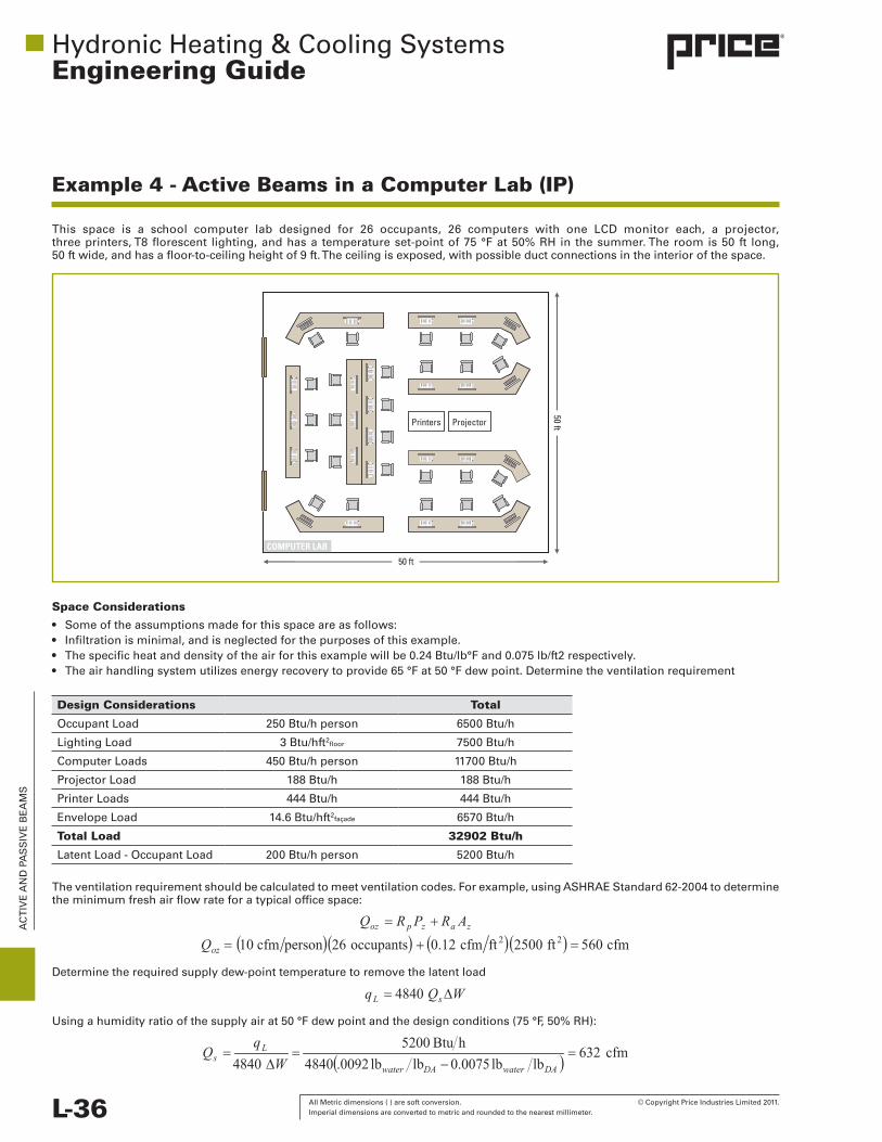
All Metric dimensions ( ) are soft conversion. © Copyright Price Industries Limited 2011. Imperial dimensions are converted to metric and rounded to the nearest millimeter. L-36
AC
TIV
E A
ND
PA
SS
IVE
BE
AM
S
HydronicHeating&CoolingSystemsEngineering Guide
Example 4 - Active Beams in a Computer Lab (IP)
This space is a school computer lab designed for 26 occupants, 26 computers with one LCD monitor each, a projector,threeprinters,T8florescent lighting,andhasa temperatureset-pointof75°Fat50%RHin thesummer.Theroomis50 ft long, 50ftwide,andhasafloor-to-ceilingheightof9ft.Theceilingisexposed,withpossibleductconnectionsintheinteriorofthespace.
Space Considerations
• Someoftheassumptionsmadeforthisspaceareasfollows:• Infiltrationisminimal,andisneglectedforthepurposesofthisexample.• Thespecificheatanddensityoftheairforthisexamplewillbe0.24Btu/lb°Fand0.075lb/ft2respectively.• Theairhandlingsystemutilizesenergyrecoverytoprovide65°Fat50°Fdewpoint.Determinetheventilationrequirement
Design Considerations Total
OccupantLoad 250Btu/hperson 6500Btu/h
LightingLoad 3Btu/hft2floor 7500Btu/h
ComputerLoads 450Btu/hperson 11700Btu/h
ProjectorLoad 188Btu/h 188Btu/h
PrinterLoads 444Btu/h 444Btu/h
EnvelopeLoad 14.6Btu/hft2façade 6570Btu/h
Total Load 32902 Btu/h
LatentLoad-OccupantLoad 200Btu/hperson 5200Btu/h
Theventilationrequirementshouldbecalculatedtomeetventilationcodes.Forexample,usingASHRAEStandard62-2004todeterminetheminimumfreshairflowrateforatypicalofficespace:
Determinetherequiredsupplydew-pointtemperaturetoremovethelatentload
Usingahumidityratioofthesupplyairat50°Fdewpointandthedesignconditions(75°F,50%RH):
Printers Projector
COMPUTER LAB
50 ft
50 ft

© Copyright Price Industries Limited 2011. All Metric dimensions ( ) are soft conversion. Imperial dimensions are converted to metric and rounded to the nearest millimeter. L-37
AC
TIV
E A
ND
PA
SS
IVE
BE
AM
S
HydronicHeating&CoolingSystemsEngineering Guide
Thesupplyairvolumetotheofficeisthemaximumofthevolumerequiredbycodeforventilationandthevolumerequiredforcontrollingthelatentload:
Using software to select a beam with the following requirements:
Example 4 - Active Beams in a Computer Lab (IP)
Performance
TotalCapacity 32902Btu/h
AirFlowRequiredforDehumidification 632cfm
SupplyAirTemperature 65°F
Arrivesatthefollowingoptions:
Parameter Option 1 (ACBL) Option 2 (ACBL) Option 3 (ACBM)
TotalCapacity 32197Btu/h 33044Btu/h 32933Btu/h
Quantity 4 6 6
Length 120in. 96 in. 48in.
Width 24in. 24in. 24in.
AirFlow 640cfm 780cfm 870cfm
Throw 11ft 17ft -
AirPressureDrop 0.99 in. 0.76in. 0.83in.
TransferEfficiency 50.3Btu/hcfm 42.4Btu/hcfm 37.9Btu/hcfm
WaterFlowRate 5.96gpm 6.48gpm 9.42gpm
WaterPressureDrop 9.9 ft hd 4.6fthd 0.71fthd
NC 27 30 -
Oftheseoptions,thesecondcombinationofsix8ftlongbeamsisthebestcombinationofcapacity,efficiencyandthrow.Withsixbeams,thesecouldbelaidoutasshownbelow:
COMPUTER LAB
Printers Projector
CHW
SCH
WR
BeamBeam Beam
BeamBeam Beam

All Metric dimensions ( ) are soft conversion. © Copyright Price Industries Limited 2011. Imperial dimensions are converted to metric and rounded to the nearest millimeter. L-38
Active & Passive BeamsEngineering Guide
L-38 All Metric dimensions ( ) are soft conversion. © Copyright Price Industries Limited 2011. Imperial dimensions are converted to metric and rounded to the nearest millimeter.
EN
GIN
EE
RIN
G G
UID
E -
AC
TIV
E &
PA
SS
IVE
BE
AM
S
Example 4 - Active Beams in a Computer Lab (SI)
Thisspaceisaschoolcomputerlabdesignedfor26occupants,26computerswithoneLCDmonitoreach,aprojector,3printers,T8florescentlighting,andhasatemperatureset-pointof24°Cat50%RHinthesummer.Theroomis15mlong,15mwide,andhasafloor-to-ceilingheightof3m.Theceilingisexposed,withductconnectionspossibleintheinteriorofthespace.
15 m
15 m
Printers Projector
COMPUTER LAB
Space ConsiderationsSomeoftheassumptionsmadeforthisspaceareasfollows:
• Infiltrationisminimal,andisneglectedforthepurposesofthisexample.• Thespecificheatanddensityoftheairwillbe1.007kgKand1.3kg/m3respectively.• Theairhandlingsystemutilizesenergyrecoverytoprovide18°Cat10°Cdewpoint.
Design Considerations Total
OccupantLoad 75W/person 1950W
LightingLoad 25W/m2floor 5625 W
ComputerLoads 130W/person 3380W
ProjectorLoad 55 W 55 W
PrinterLoads 130W 130W
EnvelopeLoad 46W/m2façade 2070W
Total Load 13210 W
LatentLoads-OccupantLoad 60W/person 1560W
Determine the ventilation requirementTheventilationrequirementshouldbecalculatedtomeetventilationcodes.Forexample,usingASHRAEStandard62-2004todeterminetheminimumfreshairflowrateforatypicalofficespace:
Determinetherequiredsupplydew-pointtemperaturetoremovethelatentload.
Usingahumidityratioofthesupplyairat10°Cdewpointandthedesignconditions(24°C,50%RH):

© Copyright Price Industries Limited 2011. All Metric dimensions ( ) are soft conversion. Imperial dimensions are converted to metric and rounded to the nearest millimeter. L-39
Active & Passive BeamsEngineering Guide
© Copyright Price Industries Limited 2011. All Metric dimensions ( ) are soft conversion. Imperial dimensions are converted to metric and rounded to the nearest millimeter. L-39
EN
GIN
EE
RIN
G G
UID
E -
AC
TIV
E &
PA
SS
IVE
BE
AM
S
Thesupplyairvolumetotheofficeisthemaximumvolumerequiredbycodeforventilationandthevolumerequiredforcontrollingthelatentload:
Using software, select a beam with the following requirements:
Example 4 - Active Beams in a Computer Lab (SI)
Performance
TotalCapacity 13210W
AirFlowRequiredforDehumidification 320L/s
SupplyAirTemperature 18°C
Arrivesatthefollowingoptions:
Parameter Option 1 (ACBL) Option 2 (ACBL) Option 3 (ACBM)
TotalCapacity 13221W 13216W 13220W
Quantity 6 7 8
Length 3000mm 2400mm 1200mm
Width 600 mm 600 mm 600 mm
AirFlow 426L/s 497L/s 696L/s
Throw 3.3m 6 m -
AirPressureDrop 220 Pa 250 Pa 193Pa
TransferEfficiency 31Ws/L 17Ws/L 19Ws/L
WaterFlowRate 302L/s 345L/s 368L/s
WaterPressureDrop 9.92kPa 10.32kPa 9.12kPa
NC 27 33 -
Oftheseoptions,thesecondcombinationofsix2.4mbeamsisthebestcombinationofcapacity,efficiencyandthrow.Withsixbeams,thesecouldbelaidoutasshownbelow:
COMPUTER LAB
Printers Projector
CHW
SCH
WR
BeamBeam Beam
BeamBeam Beam

All Metric dimensions ( ) are soft conversion. © Copyright Price Industries Limited 2011. Imperial dimensions are converted to metric and rounded to the nearest millimeter. L-40
Active & Passive BeamsEngineering Guide
L-40 All Metric dimensions ( ) are soft conversion. © Copyright Price Industries Limited 2011. Imperial dimensions are converted to metric and rounded to the nearest millimeter.
EN
GIN
EE
RIN
G G
UID
E -
AC
TIV
E &
PA
SS
IVE
BE
AM
S
Example 5 - Active Beams in Laboratories (IP)
Thishospital laboratory isused for the testingofspecimensassociatedwithpatientcare.The layout featuresone islandbenchand twowall benches to accommodate amaximumof ten clinical lab technicians. Florescent lighting, refrigerationequipmentandotherbenchdevices all generateheatwithin the lab.Thereare also two low-flow fumehoods in the cornersof the room,operatingataconstantvolumeexhaustflowrateof480cfmeach.Theroomis36 ft longby20 ftwide,withaceilingheightof 12ft.Thespaceisaninteriorzoneofthebuildingwithnoenvelopeload.
Aisle
Aisle Fume Hood
Fume Hood
20 ft
36 ft.
Cabinets/Work Surface
Space ConsiderationsSomeoftheassumptionsmadeforthisspaceareasfollows:
• Load/personis250Btu/hsensibleand200Btu/hlatent• Lightingloadinthespaceis8.3Btu/hft2
• Thespecificheatanddensityoftheairforthisexampleare0.24Btu/lb°Fand0.075Btu/hft2respectively• Minimumexhaustflowrateof6achinaccordancewithASHRAEStandard170-2008• Maintaina20%offsetbetweensupplyandexhaustvolumeinordertomaintainnegativepressure
Design Considerations
Area 720ft2
CeilingHeight 12ft
DesignConditions Summer–75°F,50%RH
Occupants 10
OccupantLoad 2500Btu/hsensible 2000Btu/hlatent
LightingLoad 6000Btu/hsensible
EquipmentLoad 31800Btu/hsensible
Total load, qt40300Btu/hsensible 2000Btu/hlatent
Number of lab hoods 2
FumeHoodExhaustAirVolume 960 cfm

© Copyright Price Industries Limited 2011. All Metric dimensions ( ) are soft conversion. Imperial dimensions are converted to metric and rounded to the nearest millimeter. L-41
Active & Passive BeamsEngineering Guide
© Copyright Price Industries Limited 2011. All Metric dimensions ( ) are soft conversion. Imperial dimensions are converted to metric and rounded to the nearest millimeter. L-41
EN
GIN
EE
RIN
G G
UID
E -
AC
TIV
E &
PA
SS
IVE
BE
AM
S
1. Determine the exhaust requirementTheexhaustrequirementisdictatedbytheexhaustrequiredbythefumehoods,aswellasbylocalcodes.Forexample,usingASHRAEStandard170-2008todeterminetheminimumfreshairflowrate:
2. Determine the ventilation requirementInordertomaintainnegativepressure,theventilationrequirementistakenas80%oftheexhaustairflowrate:
3.Determinetherequiredsupplydew-pointtemperaturetoremovethelatentloadFromequationH2:
Atthedesignconditions(75°F,50%RH),thehumidityratiois65gr/lbofdryair,requiring:
Fromthefigurebelow,thedewpointcorrespondingtothehumidityratiois54°F.Thisisreadilyachievedbystandardequipment,andthereforedoesnotneedtobeadjusted.Withtheairchangerequirementdeterminedbycodenearlyequivalenttotheairvolumerequirementdictatedbythefumehoodexhaust,wewill,inthisapplication,opttouseaconstantvolumesupplyairsystem.
Example 5 - Active Beams in Laboratories (IP)
0.000
0.002
0.004
0.006
0.012
0.014
0.016
0.018
0.020
0.022
0.024
0.026
0.028
0.030
35 40
12.5
13.0
13.5 10%
20%
30%40%
50%60%70%80%90
%
14.0
14.5
15.0
45 50 60 65 70 80 85 90 95 100 105 110 115 120
65
Dry Bulb Temperature, ºF
Enthalpy - Btu/lb
of Dry
Air
Hum
idity Ratio, lbw /lb
DA
70
75
80
85
15
20
25
30
35
40
45
50
60 65
Volume - ft3/lb of Dry Air
Saturation Temperature, ºF
Relative Humidity
40
45
50
55
60
35
0.00930.0087
54 75
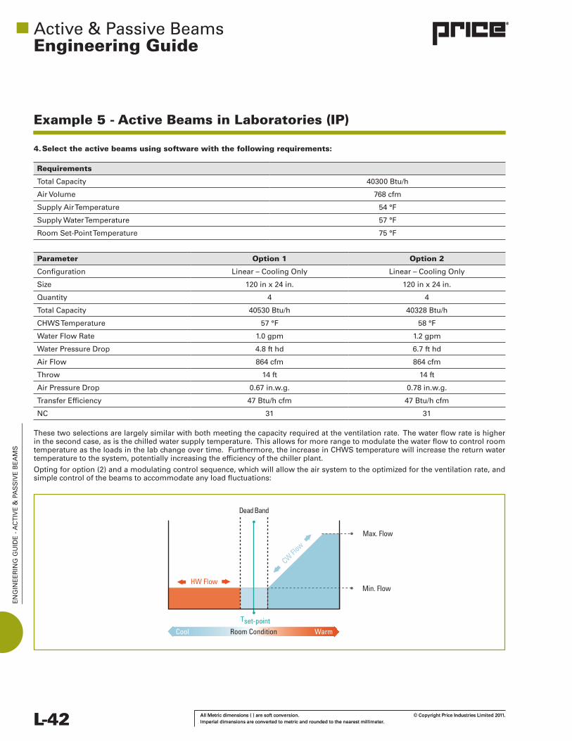
All Metric dimensions ( ) are soft conversion. © Copyright Price Industries Limited 2011. Imperial dimensions are converted to metric and rounded to the nearest millimeter. L-42
Active & Passive BeamsEngineering Guide
L-42 All Metric dimensions ( ) are soft conversion. © Copyright Price Industries Limited 2011. Imperial dimensions are converted to metric and rounded to the nearest millimeter.
EN
GIN
EE
RIN
G G
UID
E -
AC
TIV
E &
PA
SS
IVE
BE
AM
S
Example 5 - Active Beams in Laboratories (IP)
4. Select the active beams using software with the following requirements:
Parameter Option 1 Option 2
Configuration Linear–CoolingOnly Linear–CoolingOnly
Size 120inx24in. 120inx24in.
Quantity 4 4
TotalCapacity 40530Btu/h 40328Btu/h
CHWSTemperature 57°F 58°F
WaterFlowRate 1.0gpm 1.2gpm
WaterPressureDrop 4.8fthd 6.7fthd
AirFlow 864cfm 864cfm
Throw 14ft 14ft
AirPressureDrop 0.67in.w.g. 0.78in.w.g.
TransferEfficiency 47Btu/hcfm 47Btu/hcfm
NC 31 31
Requirements
TotalCapacity 40300Btu/h
AirVolume 768cfm
SupplyAirTemperature 54°F
SupplyWaterTemperature 57°F
RoomSet-PointTemperature 75°F
Thesetwoselectionsarelargelysimilarwithbothmeetingthecapacityrequiredattheventilationrate.Thewaterflowrateishigherinthesecondcase,asisthechilledwatersupplytemperature.Thisallowsformorerangetomodulatethewaterflowtocontrolroomtemperatureastheloadsinthelabchangeovertime.Furthermore,theincreaseinCHWStemperaturewillincreasethereturnwatertemperaturetothesystem,potentiallyincreasingtheefficiencyofthechillerplant.
Optingforoption(2)andamodulatingcontrolsequence,whichwillallowtheairsystemtotheoptimizedfortheventilationrate,andsimplecontrolofthebeamstoaccommodateanyloadfluctuations:
Max. Flow
Min. FlowHW Flow
Dead Band
Tset-point
CW Flo
w
Cool WarmRoom Condition

© Copyright Price Industries Limited 2011. All Metric dimensions ( ) are soft conversion. Imperial dimensions are converted to metric and rounded to the nearest millimeter. L-43
Active & Passive BeamsEngineering Guide
© Copyright Price Industries Limited 2011. All Metric dimensions ( ) are soft conversion. Imperial dimensions are converted to metric and rounded to the nearest millimeter. L-43
EN
GIN
EE
RIN
G G
UID
E -
AC
TIV
E &
PA
SS
IVE
BE
AM
S
Alternatively,theCHWStemperaturecanbemodulatedtocontroltheload,thoughitwillincreasethecomplexityofthewatersystem.
Withtheselectionof10ftlongbeamswithCoandawingstoensurepatterninanexposedapplication,thesecanbearrangedintworowsparalleltotheshortdimensionintheroom:
Example 5 - Active Beams in Laboratories (IP)
Withthisspacing,the14ftthrowto50fpmwillcovertheroomwellwith9ftofthrowtothewallandopposingairpatternand5ftfromtheceilingtothetopoftheoccupiedzone.Itislogicaltorunthesupplyandreturnpipingdownthemiddleoftheroomandhavethewaterconnectionsforthebeamsfaceeachother,asindicatedonthediagram.
Aisle
Aisle Fume Hood
Fume Hood
Cabinets/Work Surface
CHW
SCH
WR
BeamBeam
BeamBeam
Occupied Zone
8 ft
5 ft
8 ft

All Metric dimensions ( ) are soft conversion. © Copyright Price Industries Limited 2011. Imperial dimensions are converted to metric and rounded to the nearest millimeter. L-44
Active & Passive BeamsEngineering Guide
L-44 All Metric dimensions ( ) are soft conversion. © Copyright Price Industries Limited 2011. Imperial dimensions are converted to metric and rounded to the nearest millimeter.
EN
GIN
EE
RIN
G G
UID
E -
AC
TIV
E &
PA
SS
IVE
BE
AM
S
Example 5 - Active Beams in Laboratories (SI)
Thishospitallaboratoryisusedforthetestingofspecimensassociatedwithpatientcare.Thelayoutfeaturesoneislandbenchandtwowallbenchestoaccommodateamaximumoftenclinicallabtechnicians.Florescentlighting,refrigerationequipmentandotherbenchdevicesallgenerateheatwithinthelab.Therearealsotwolow-flowfumehoodsinthecornersoftheroomoperatingataconstantvolumeexhaustflowrateof225L/seach.Theroomis11mlongby6mwide,withaceilingheightof3.75m.Thespaceisaninteriorzoneofthebuildingwithnoenvelopeload.
Aisle
Aisle Fume Hood
Fume Hood
6 m
11 m
Cabinets/Work Surface
Space ConsiderationsSomeoftheassumptionsmadeforthisspaceareasfollows:
• Load/personis75Wsensibleand60Wlatent• Lightingloadinthespaceis25W/m²• Thespecificheatanddensityoftheairforthisexampleare1.007kgKand1.21kg/m³respectively• Minimumexhaustflowrateof6achinaccordancewithASHRAEStandard170-2008• Maintaina20%offsetbetweensupplyandexhaustvolumeinordertomaintainnegativepressure
Design Considerations
Area 66 m2
CeilingHeight 3.75m
DesignConditions Summer–24°C,50%RH
Occupants 10
OccupantLoad 750Wsensible 600 W latent
LightingLoad 1650Wsensible
EquipmentLoad 9500 W sensible
Total load, qt11900Wsensible
600 W latent
Number of lab hoods 2
FumeHoodExhaustAirVolume 450L/s

© Copyright Price Industries Limited 2011. All Metric dimensions ( ) are soft conversion. Imperial dimensions are converted to metric and rounded to the nearest millimeter. L-45
Active & Passive BeamsEngineering Guide
© Copyright Price Industries Limited 2011. All Metric dimensions ( ) are soft conversion. Imperial dimensions are converted to metric and rounded to the nearest millimeter. L-45
EN
GIN
EE
RIN
G G
UID
E -
AC
TIV
E &
PA
SS
IVE
BE
AM
S
1. Determine the exhaust requirementTheventilationrequirementshouldbecalculatedtomeetventilationcodes.Forexample,usingASHRAEStandard170-2008todeterminetheminimumfreshairflowrate:
2. Determine the ventilation requirementInordertomaintainnegativepressure,theventilationrequirementistakenas80%oftheexhaustairflowrate:
3. Determine the required supply dew-point temperature to remove the latent loadFromequationH2
Usingtheventilationrate:
Atthedesignconditions(24°C,50%RH),thehumidityratiois9.5g/kg,requiring:
Fromthefigurebelow,thedewpointcorrespondingtothehumidityratiois12.5°C.Thisisreadilyachievedbystandardequipment,andthereforedoesnotneedtobeadjusted.Withtheairchangerequirementdeterminedbycodenearlyequivalenttotheairvolumerequirementdictatedbythefumehoodexhaust,wewill,inthisapplication,opttouseaconstantvolumesupplyairsystem.
Example 5 - Active Beams in Laboratories (SI)
Dry-Bulb Temperature, ºC
Entha
lpy - k
J/kg o
f Dry
Air
30
25
20
15
10
5
0504540353025201550
0
45
40
35
30
25
20
15
50
55
60
65
70
75
85
90
95
100
105
105110 115 120 125
Volume - m3/kg of Dry Air
Saturation Temperature, ºC
Relative Humidity
Hum
idity Ratio, gw /kg
DA
30
10
5
15
20
0.78
0.80
0.82
0.84
0.86
0.90
0.92
0.94
0.96
10%
20%
30%40%
50%60
%70%80
%90%
25
9.238.45
12.5 24

All Metric dimensions ( ) are soft conversion. © Copyright Price Industries Limited 2011. Imperial dimensions are converted to metric and rounded to the nearest millimeter. L-46
Active & Passive BeamsEngineering Guide
L-46 All Metric dimensions ( ) are soft conversion. © Copyright Price Industries Limited 2011. Imperial dimensions are converted to metric and rounded to the nearest millimeter.
EN
GIN
EE
RIN
G G
UID
E -
AC
TIV
E &
PA
SS
IVE
BE
AM
S
Example 5 - Active Beams in Laboratories (SI)
4. Select the active beams using software with the following requirements:
Requirements
TotalCapacity 11900W
AirVolume 360L/s
SupplyAirTemperature 12.5°C
SupplyWaterTemperature 14°C
RoomSet-PointTemperature 24°C
Parameter Option 1 Option 2
Size 300mmx600mm 300mmx600mm
Configuration Linear–CoolingOnly Linear–CoolingOnly
Quantity 4 4
TotalCapacity 13022W 12689W
CHWSTemperature 14°C 15°C
WaterFlowRate 245L/h 318L/h
WaterPressureDrop 16.7kPa 26.6kPa
AirFlow 453L/s 453L/s
Throw 4.6m 4.6m
AirPressureDrop 202 Pa 202 Pa
TransferEfficiency 46Ws/L 45Ws/L
NC - -
Thesetwoselectionsarelargelysimilarwithbothmeetingthecapacityrequiredattheventilationrate.Thewaterflowrateishigherinthesecondcase,asisthechilledwatersupplytemperature.Thisallowsformorerangetomodulatethewaterflowtocontrolroomtemperatureastheloadsinthelabchangeovertime.Furthermore,theincreaseinCHWStemperaturewillincreasethereturnwatertemperaturetothesystem,potentiallyincreasingtheefficiencyofthechillerplant.
Optingforoption(2)andamodulatingcontrolsequencewhichwillallowtheairsystemtotheoptimizedfortheventilationrateandsimplecontrolofthebeamstoaccommodateanyloadfluctuations:
Max. Flow
Min. FlowHW Flow
Dead Band
Tset-point
CW Flo
w
Cool WarmRoom Condition

© Copyright Price Industries Limited 2011. All Metric dimensions ( ) are soft conversion. Imperial dimensions are converted to metric and rounded to the nearest millimeter. L-47
Active & Passive BeamsEngineering Guide
© Copyright Price Industries Limited 2011. All Metric dimensions ( ) are soft conversion. Imperial dimensions are converted to metric and rounded to the nearest millimeter. L-47
EN
GIN
EE
RIN
G G
UID
E -
AC
TIV
E &
PA
SS
IVE
BE
AM
S
Example 5 - Active Beams in Laboratories (SI)
Alternatively,theCHWStemperaturecanbemodulatedtocontroltheload,thoughitwillincreasethecomplexityofthewatersystem.
Withtheselectionof3mlongbeamswithCoandawingstoensurepatterninanexposedapplication,thesecanbearrangedintworowsparalleltotheshortdimensionintheroom:
Aisle
Aisle Fume Hood
Fume Hood
Cabinets/Work Surface
CHW
SCH
WR
BeamBeam
BeamBeam
Withthisspacing,the4.5mthrowto0.25m/swillcovertheroomwellwith3mofthrowtothewallandopposingairpatternand1.5mfromtheceilingtothetopoftheoccupiedzone.Itislogicaltorunthesupplyandreturnpipingdownthemiddleoftheroomandhavethewaterconnectionsforthebeamsfaceeachother,asindicatedonthediagram.
Occupied Zone
3 m
1.5 m
3 m

All Metric dimensions ( ) are soft conversion. © Copyright Price Industries Limited 2011. Imperial dimensions are converted to metric and rounded to the nearest millimeter. L-48
Active & Passive BeamsEngineering Guide
L-48 All Metric dimensions ( ) are soft conversion. © Copyright Price Industries Limited 2011. Imperial dimensions are converted to metric and rounded to the nearest millimeter.
EN
GIN
EE
RIN
G G
UID
E -
AC
TIV
E &
PA
SS
IVE
BE
AM
S
Active&PassiveBeamsEngineering Guide
References
ASHRAE(2004).Standard 62-2004—Ventilation for acceptable indoor air quality.Atlanta,GA:AmericanSocietyfor Heating,RefrigeratingandAir-ConditioningEngineers.
ASHRAE(2007).Humidity control design guide.Atlanta,GA:AmericanSocietyforHeating,RefrigeratingandAir- ConditioningEngineers.
ASHRAE(2008).Standard 170-2008—Ventilation of health care facilities. Atlanta,GA:AmericanSocietyofHeating, Refrigerating,andAir-ConditioningEngineers.
ASHRAE(2009).ASHRAE handbook—Fundamentals.Atlanta,GA:AmericanSocietyofHeating,Refrigerating,and Air-ConditioningEngineers.
ASHRAE(2010).Standard 62.1-2010—Ventilation for acceptable indoor air quality.Atlanta,GA:AmericanSocietyof Heating,Refrigerating,andAir-ConditioningEngineers.
CSA(2010).CSA Z317.0-10—Special requirements for heating, ventilation, and air-conditioning (HVAC) systems in health care facilities.Mississauga,ON:CanadianStandardsAssociation.
Mumma,S.A.(2002).Chilledceilingsinparallelwithdedicatedoutdoorairsystems:Addressingtheconcernsof condensation,capacityandcost.ASHRAE Transactions 2002(2),220–231.
Price Industries (2011). Price engineer’s HVAC handbook—A comprehensive guide to HVAC fundamentals. Winnipeg,MB:PriceIndustriesLimited.
Stetiu,C.(1998).RadiantcoolinginU.S.officebuildings:Towardseliminatingtheperceptionclimateimposedbarriers. DoctorialDissertation,EnergyandResourcesGroup,UniversityofCaliforniaatBerkeley,CA.
Virta,M.,Butler,D.,Gräslund,J.,Hogeling,J.,Kristiansen,E.L.,Reinikainen,M.,&Svensson,G. (2004).REHVA guidebook no. 5: Chilled beam application guidebook.Brussels,Belgium:FederationofEuropeanHeatingand Air-conditioningAssociations(REHVA).