ACTIVE DRIVER PLUS M/T 1.0 ACTIVE DRIVER PLUS M/T 2.2 ... · instruÇÕes para a instalaÇÃo e a...
47
ISTRUZIONI PER L'INSTALLAZIONE E LA MANUTENZIONE INSTRUCTIONS FOR INSTALLATION AND MAINTENANCE INSTRUCTIONS POUR L'INSTALLATION ET LA MAINTENANCE INSTALLATIONS- UND WARTUNGSANLEITUNGEN INSTRUCTIES VOOR INSTALLATIE EN ONDERHOUD INSTRUCCIONES DE INSTALACIÓN Y MANTENIMIENTO INSTALLATIONS- OCH UNDERHÅLLSANVISNING ΟΔΗΓΙΕΣ ΓΙΑ ΤΗΝ ΕΓΚΑΤΑΣΤΑΣΗ ΚΑΙ ΤΗ ΣΥΝΤΗΡΗΣΗ KURMA VE BAKIM BİLGİLERİ NÁVOD NA INŠTALÁCIU A ÚDRŽBU РУКОВОДСТВО ПО МОНТАЖУ И ТЕХНИЧЕСКОМУ ОБСЛУЖИВАНИЮ INSTRUCTIUNI PENTRU INSTALARE SI INTRETINERE INSTRUÇÕES PARA A INSTALAÇÃO E A MANUTENÇÃO ASENNUS- JA HUOLTO-OHJEET INSTRUKCJA MONTAŻU I KONSERWACJI ІНСТРУКЦІЇ ЗІ ВСТАНОВЛЕННЯ ТА ТЕХНІЧНОГО ОБСЛУГОВУВАННЯ NÁVOD K INSTALACI A ÚDRŽBĚ لصيانة وا التركيب بعملية خاصةدات إرشاACTIVE DRIVER PLUS M/T 1.0 ACTIVE DRIVER PLUS M/T 2.2 ACTIVE DRIVER PLUS T/T 3 ACTIVE DRIVER PLUS T/T 5.5 ACTIVE DRIVER PLUS M/M 1.1 ACTIVE DRIVER PLUS M/M 1.8 / DV ACTIVE DRIVER PLUS M/M 1.5 / DV
Transcript of ACTIVE DRIVER PLUS M/T 1.0 ACTIVE DRIVER PLUS M/T 2.2 ... · instruÇÕes para a instalaÇÃo e a...
ISTRUZIONI PER L'INSTALLAZIONE E LA MANUTENZIONE INSTRUCTIONS FOR INSTALLATION AND MAINTENANCE
INSTRUCTIONS POUR L'INSTALLATION ET LA MAINTENANCE INSTALLATIONS- UND WARTUNGSANLEITUNGEN
INSTRUCTIES VOOR INSTALLATIE EN ONDERHOUD
INSTRUCCIONES DE INSTALACIÓN Y MANTENIMIENTO
INSTALLATIONS- OCH UNDERHÅLLSANVISNING ΟΔΗΓΙΕΣ ΓΙΑ ΤΗΝ ΕΓΚΑΤΑΣΤΑΣΗ ΚΑΙ ΤΗ ΣΥΝΤΗΡΗΣΗ
KURMA VE BAKIM BİLGİLERİ
NÁVOD NA INŠTALÁCIU A ÚDRŽBU РУКОВОДСТВО ПО МОНТАЖУ И ТЕХНИЧЕСКОМУ ОБСЛУЖИВАНИЮ
INSTRUCTIUNI PENTRU INSTALARE SI INTRETINERE INSTRUÇÕES PARA A INSTALAÇÃO E A MANUTENÇÃO
ASENNUS- JA HUOLTO-OHJEET INSTRUKCJA MONTAŻU I KONSERWACJI
ІНСТРУКЦІЇ ЗІ ВСТАНОВЛЕННЯ ТА ТЕХНІЧНОГО ОБСЛУГОВУВАННЯ NÁVOD K INSTALACI A ÚDRŽBĚ إرشادات خاصة بعملية التركيب والصيانة
ACTIVE DRIVER PLUS M/T 1.0
ACTIVE DRIVER PLUS M/T 2.2
ACTIVE DRIVER PLUS T/T 3
ACTIVE DRIVER PLUS T/T 5.5
ACTIVE DRIVER PLUS M/M 1.1
ACTIVE DRIVER PLUS M/M 1.8 / DV
ACTIVE DRIVER PLUS M/M 1.5 / DV

ENGLISH
47
INDEX KEY .................................................................................................................................................................. 51 WARNINGS ..................................................................................................................................................... 51
Special warnings ....................................................................................................................................... 52 RESPONSIBILITY ........................................................................................................................................... 52 1 GENERAL INFORMATION ...................................................................................................................... 52
1.1 Applications ..................................................................................................................................... 53 1.2 Technical specifications ................................................................................................................. 53
2 INSTALLATION ........................................................................................................................................ 55 2.1 Hydraulic connection ...................................................................................................................... 55
2.1.1 Single pump installation .................................................................................................................. 56 2.1.2 Multipump installation ..................................................................................................................... 56
2.2 Electrical connections..................................................................................................................... 56 2.2.1 Pump connection for M/T and T/T models ................................................................................. 57 2.2.2 Pump connection for M/M models .............................................................................................. 57
2.3 CONNECTION TO THE POWER SUPPLY LINE ............................................................................. 57 2.3.1 Connection to the power supply for M/T and M/M models ......................................................... 58 2.3.2 Connection to the power supply for T/T models ......................................................................... 58 2.3.3 Connection of user inputs ........................................................................................................... 59 2.3.4 Connection of the user outputs .................................................................................................. 61 2.3.5 Connection of the remote sensor ............................................................................................... 61 2.3.6 Connection of the multi-inverter communication ........................................................................ 62
2.4 Configuration of the Integrated Inverter ........................................................................................ 62 2.5 Priming ............................................................................................................................................. 62 2.6 Operation .......................................................................................................................................... 63
3 KEYBOARD AND DISPLAY .................................................................................................................... 63 3.1 Menus ............................................................................................................................................... 64 3.2 Access to menus ............................................................................................................................. 64
3.2.1 Direct access with button combinations ......................................................................................... 64 3.2.2 Access by name via drop-down menus .......................................................................................... 66
3.3 Structure of menu pages ................................................................................................................ 67 3.4 Parameter setting block via Password .......................................................................................... 68 3.5 Enabling and disabling the motor .................................................................................................. 69
4 MULTI INVERTER SYSTEM .................................................................................................................... 69 4.1 Introduction to multi inverter systems .......................................................................................... 69 4.2 Setting up a multi inverter system ................................................................................................. 69
4.2.1 Communication ............................................................................................................................... 69 4.2.2 Remote sensor in multi-inverter systems ....................................................................................... 69 4.2.3 Connection and setting of the optical coupling inputs .................................................................... 69
4.3 Multi inverter operating parameters .............................................................................................. 70 4.3.1 Parameters related to multi inverter systems ................................................................................. 70
4.3.1.1 Local parameters...................................................................................................................... 70 4.3.1.2 Sensitive parameters ............................................................................................................... 70 4.3.1.3 Parameters with optional alignment ......................................................................................... 71
4.4 Initial start-up of multiple inverter system .................................................................................... 71 4.5 Multi-inverter settings ..................................................................................................................... 71
4.5.1 Assigning the start-up order ............................................................................................................ 71 4.5.1.1 Maximum operating time .......................................................................................................... 71 4.5.1.2 Reaching of maximum inactivity time ....................................................................................... 72
4.5.2 Reserves and number of inverters involved in pumping ................................................................ 72 5 POWER-UP AND START-UP .................................................................................................................. 72
5.1 Initial power-up operations ............................................................................................................. 72 5.2 Wizard ............................................................................................................................................... 72
5.2.1 Setting the language LA ................................................................................................................. 73 5.2.2 Setting the measurement system MS ............................................................................................. 73 5.2.3 Setting the pressure setpoint SP .................................................................................................... 73 5.2.4 Setting the rated frequency of the pump FN ................................................................................... 73 5.2.5 Setting the rated voltage of the pump UN ...................................................................................... 73 5.2.6 Setting the rated current RC ........................................................................................................... 73 5.2.7 Setting the direction of rotation RT ................................................................................................. 73 5.2.8 Setting other parameters ................................................................................................................ 73
5.3 Troubleshooting on initial installation .......................................................................................... 74
ENGLISH
48
6 KEY TO INDIVIDUAL PARAMETERS ..................................................................................................... 75 6.1 User menu ........................................................................................................................................ 75
6.1.1 FR: Display of rotation frequency ................................................................................................... 75 6.1.2 VP: Display of pressure .................................................................................................................. 75 6.1.3 C1: Display of phase current .......................................................................................................... 75 6.1.4 PO: Display of the power delivered ................................................................................................ 75 6.1.5 PI: Power histogram ....................................................................................................................... 75 6.1.6 SM: System monitor ....................................................................................................................... 75 6.1.7 VE: Display of version ..................................................................................................................... 75
6.2 Monitor menu ................................................................................................................................... 76 6.2.1 VF: Flow display .............................................................................................................................. 76 6.2.2 TE: Display of final power stage temperature ................................................................................. 76 6.2.3 BT: Display of electronic board temperature .................................................................................. 76 6.2.4 FF: Display of fault log .................................................................................................................... 76 6.2.5 CT: Display contrast ....................................................................................................................... 76 6.2.6 LA: Language .................................................................................................................................. 76 6.2.7 HO: Operating hours ....................................................................................................................... 76 6.2.8 EN: absorbed energy counter ......................................................................................................... 76 6.2.9 SN: Number of starts ...................................................................................................................... 77
6.3 Setpoint menu .................................................................................................................................. 77 6.3.1 SP: Setting the setpoint pressure ................................................................................................... 77 6.3.2 Auxiliary pressure settings .............................................................................................................. 77
6.3.2.1 P1: Auxiliary pressure 1 setting ................................................................................................ 77 6.3.2.2 P2: Auxiliary pressure 2 setting ................................................................................................ 77 6.3.2.3 P3: Auxiliary pressure 3 setting ................................................................................................ 77
6.4 Manual menu .................................................................................................................................... 77 6.4.1 FP: Test frequency setting .............................................................................................................. 78 6.4.2 VP: Display of pressure .................................................................................................................. 78 6.4.3 C1: Display of phase current .......................................................................................................... 78 6.4.4 PO: Display of the power delivered ................................................................................................ 78 6.4.5 RT: Setting the direction of rotation ................................................................................................ 78 6.4.6 VF: Flow display .............................................................................................................................. 78
6.5 Installer menu .................................................................................................................................. 78 6.5.1 RC: Electric pump rated current setting .......................................................................................... 78 6.5.2 RT: Setting the direction of rotation ................................................................................................ 78 6.5.3 FN: Rated frequency settings ......................................................................................................... 79 6.5.4 UN: Setting the rated voltage .......................................................................................................... 79 6.5.5 OD: Type of system ........................................................................................................................ 79 6.5.6 RP: Setting the pressure drop for restart ........................................................................................ 79 6.5.7 AD: Address configuration .............................................................................................................. 79 6.5.8 PR: Pressure sensor ....................................................................................................................... 79 6.5.9 MS: Measurement system .............................................................................................................. 80 6.5.10 SX: Setpoint massimo .................................................................................................................. 80
6.6 Technical Assistance Menu ............................................................................................................ 80 6.6.1 TB: Water failure block time ............................................................................................................ 80 6.6.2 T1: Shutdown time after low pressure signal .................................................................................. 80 6.6.3 T2: Shutdown delay ........................................................................................................................ 80 6.6.4 GP: Proportional gain coefficient .................................................................................................... 80 6.6.5 GI: Integral gain coefficient ............................................................................................................. 81 6.6.6 FS: Maximum rotation frequency .................................................................................................... 81 6.6.7 FL: Minimum rotation frequency ..................................................................................................... 81 6.6.8 Setting the number of inverters and reserves ................................................................................ 81
6.6.8.1 NA: Active inverters .................................................................................................................. 81 6.6.8.2 NC: Simultaneous inverters ..................................................................................................... 81 6.6.8.3 IC: Reserve configuration ......................................................................................................... 81 6.6.8.4 Examples of configuration for multi-inverter systems .............................................................. 82
6.6.9 ET: Exchange time ......................................................................................................................... 82 6.6.10 CF: Carrier frequency ................................................................................................................... 82 6.6.11 AC: Acceleration ........................................................................................................................... 82 6.6.12 AY: Anti cycling ............................................................................................................................. 82 6.6.13 AE: Enabling the anti-blocking function ........................................................................................ 83 6.6.14 AF: Anti freeze .............................................................................................................................. 83

ENGLISH
49
6.6.15 Setup of auxiliary digital inputs IN1, IN2, IN3, IN4 ........................................................................ 83 6.6.15.1 Disabling functions associated with input .............................................................................. 84 6.6.15.2 Setting the external float function ........................................................................................... 84 6.6.15.3 Setting the auxiliary pressure input function .......................................................................... 84 6.6.15.4 Setting the system enable and fault reset .............................................................................. 85 6.6.15.5 Setting low pressure detection (KIWA) .................................................................................. 86
6.6.16 Setup of outputs OUT1, OUT2 ..................................................................................................... 86 6.6.16.1 O1: Output 1 function setting ................................................................................................. 86 6.6.16.2 O2: Output 2 function setting .................................................................................................. 86
6.6.17 SF: Starting frequency .................................................................................................................. 87 6.6.18 ST: Starting time ........................................................................................................................... 87 6.6.19 RF: Fault and warning log reset.................................................................................................... 87 6.6.20 PW: Change password ................................................................................................................. 87 6.6.21 Password for multipump systems ................................................................................................. 88
7 PROTECTION SYSTEMS ........................................................................................................................ 88 7.1 Protection systems .......................................................................................................................... 88
7.1.1 Anti-Freeze (Protection against freezing of water in the system) ................................................... 88 7.2 Description of blocks ...................................................................................................................... 89
7.2.1 “BL” Block due to water failure ........................................................................................................ 89 7.2.2 “BP1” Block due to fault on pressure sensor .................................................................................. 89 7.2.3 "LP" Block due to low power supply voltage ................................................................................... 89 7.2.4 "HP" Block due to high internal power supply voltage .................................................................... 89 7.2.5 "SC" Block due to direct short circuit between the phases on the output terminal ......................... 89
7.3 Manual reset of error conditions .................................................................................................... 89 7.4 Auto-reset of error conditions ........................................................................................................ 89
8 RESET AND FACTORY SETTINGS ........................................................................................................ 90 8.1 General system reset ...................................................................................................................... 90 8.2 Factory settings ............................................................................................................................... 90 8.3 Restoring the factory settings ........................................................................................................ 90
9 Firmware update ..................................................................................................................................... 92 9.1 General ............................................................................................................................................. 92 9.2 Update ............................................................................................................................................... 92
INDEX OF TABLE Table 1: Product families .......................................................................................................................... 51 Table 2: Technical data and limitations of use ......................................................................................... 54 Table 3: Section of power cables for M/M and M/T inverters ................................................................... 58 Table 4: Section of 4-wire cable (3 phases + earth) ................................................................................. 58 Table 5: Input connection ......................................................................................................................... 59 Table 6: Input specifications ..................................................................................................................... 61 Table 7: Output connection ....................................................................................................................... 61 Table 8: Output contact specifications ...................................................................................................... 61 Table 9: Connection of the remote pressure sensor ................................................................................ 61 Table 10: Connection of the multi-inverter communication ...................................................................... 62 Table 11: Button functions ........................................................................................................................ 63 Table 12: Access to menus ...................................................................................................................... 64 Table 13: Menu structure .......................................................................................................................... 66 Table 14: Error status messages on main page ....................................................................................... 68 Table 15: Status bar indications ............................................................................................................... 68 Table 16: Wizard ....................................................................................................................................... 72 Table 17: Troubleshooting ........................................................................................................................ 74 Table 18: Display of SM system monitor .................................................................................................. 75 Table 19: Setting of the remote pressure sensor ..................................................................................... 80 Table 20: Unit of measurement system .................................................................................................... 80 Table 21: Default settings of inputs .......................................................................................................... 83 Table 22: Input configuration .................................................................................................................... 84 Table 23: External float function ............................................................................................................... 84 Table 24: Auxiliary setpoints ..................................................................................................................... 85 Table 25: System enable and fault reset .................................................................................................. 85 Table 26: Low pressure signal detection (KIWA) ..................................................................................... 86 Table 27: Default output settings .............................................................................................................. 86 Table 28: Output configuration ................................................................................................................. 87 Table 29: Allarms ...................................................................................................................................... 88

ENGLISH
50
Table 30: Block information ...................................................................................................................... 88 Table 31: Auto-reset of blocks .................................................................................................................. 90 Table 32: Factory settings ........................................................................................................................ 91
INDEX OF FIGURES Figure 1: Hydraulic installation .................................................................................................................. 56 Figure 2: Input connection ........................................................................................................................ 60 Figure 3: Output connection ..................................................................................................................... 61 Figure 4: Connection of the multi-inverter communication ....................................................................... 62 Figure 6: Appearance of the user interface .............................................................................................. 63 Figure 7: Drop-down menu selection ........................................................................................................ 66 Figure 8: Optional menu access scheme ................................................................................................. 67 Figure 9: Menu parameter display ............................................................................................................ 68 Figure 10: Power histogram ...................................................................................................................... 75 Figure 11: Setting the restart pressure ..................................................................................................... 79

ENGLISH
51
KEY In this document, the following symbols have been used:
General danger. Failure to observe the warnings alongside this symbol can cause damage or physical injury.
Risk of electric shock. Failure to observe the warnings alongside this symbol can cause serious hazards with risk to personal safety.
Notes
WARNINGS This manual refers to the products Active Driver Plus M/T 1.0 Active Driver Plus M/T 2.2 Active Driver Plus T/T 3 Active Driver Plus T/T 5.5 Active Driver Plus M/M 1.1 Active Driver Plus M/M 1.8 / DV Active Driver Plus M/M 1.5 / DV The above products can be classified in families according to their characteristics. The subdivision by family is as follows:
Family Product
M/T ACTIVE DRIVER PLUS M/M 1.1 ACTIVE DRIVER PLUS M/M 1.5 / DV
T/T ACTIVE DRIVER PLUS M/M 1.8 / DV ACTIVE DRIVER PLUS M/T 1.0
M/M ACTIVE DRIVER PLUS M/T 2.2 ACTIVE DRIVER PLUS T/T 3 ACTIVE DRIVER PLUS T/T 5.5
Table 1: Product families
In the discussion below, the term “inverter” will be used when the characteristics are common to all models. If the characteristics differ, the family or product concerned will be specified.
Read this documentation carefully before installation. Installation and operation must comply with the local safety regulations in force in the country in which the product is installed. Everything must be done in a workmanlike manner. Failure to respect the safety regulations not only causes risk to personal safety and damage to the equipment, but invalidates every right to assistance under guarantee.
Skilled personnel It is advisable that installation be carried out by competent, skilled personnel in possession of the technical qualifications required by the specific legislation in force. The term skilled personnel means persons whose training, experience and instruction, as well as their knowledge of the respective standards and requirements for accident prevention and working conditions, have been approved by the person in charge of plant safety, authorizing them to perform all the nec-essary activities, during which they are able to recognize and avoid all dangers. (Definition for technical personnel IEC 364). The appliance is not intended to be used by persons (including children) with reduced physical, sensory or mental capacities, or who lack experience or knowledge, unless, through the mediation of a person responsible for their safety, they have had the benefit of supervision or of instructions on the use of the appliance. Children must be supervised to ensure that they do not play with the appliance.

ENGLISH
52
Safety Use is allowed only if the electric system is in possession of safety precautions in accordance with the regulations in force in the country where the product is installed (for Italy CEI 64/2).
Pumped liquids The machine has been designed and made for pumping water, free from explosive substances and solid particles or fibres, with a density of 1000 Kg/m³, a kinematic viscosity of 1mm²/s and non chemically aggressive liquids.
The power supply cable must never be used to carry or shift the pump. Never pull on the cable to detach the plug from the socket.
If the power cable is damaged, it must be replaced by the manufacturer or by their authorised technical assistance service, so as to avoid any risk.
Failure to observe the warnings may create situations of risk for persons or property and will void the product guarantee.
Special warnings
Before working on the electrical or mechanical part of the system, always turn off the mains voltage. Wait at least five minutes after the power supply to the machine has been switched off before opening the appliance. The capacitor of the continuous intermediate circuit remains charged with dangerously high voltage even after the mains voltage has been switched off. Only firmly wired mains connections are admissible. The appliance must be earthed (IEC 536 class 1, NEC and other relevant standards).
Mains and motor terminals may carry dangerous voltage even when the motor is stopped.
In specific calibration conditions, after a power failure the converter may start automatically. Do not operate the appliance when exposed to direct sunlight. This appliance may not be used as an “EMERGENCY STOP mechanism” (see EN 60204, 9.2.5.4).
RESPONSIBILITY The Manufacturer does not vouch for correct operation of the electropumps or answer for any damage that they may cause if they have been tampered with, modified and/or run outside the recommended work range or in contrast with other indications given in this manual. The Manufacturer declines all responsibility for possible errors in this instructions manual, if due to misprints or errors in copying. The Manufacturer reserves the right to make any modifications to products that it may consider necessary or useful, without affecting their essential characteristics.
1 GENERAL INFORMATION
Inverter for electropumps designed for pressure boosting in hydraulic plants by measuring the pressure and the flow.
There are a wide range of operating modes and optional accessories. By means of the various possible settings and availability of configurable inputs and outputs, operation of the inverter can be adapted to meet the requirements of all systems. 6 SIGNIFICATO DEI SINGOLI PARAMETRI specifies the various settable values: pressure, protection cut-out trip, frequency of rotation, etc. In this manual the pump will also be referred to in the abbreviated form "inverter", when dealing with common characteristics.
ENGLISH
53
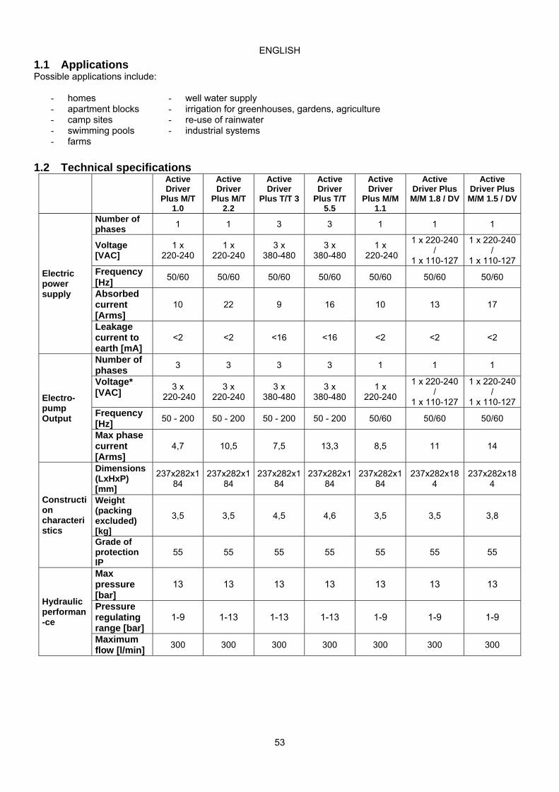
1.1 Applications Possible applications include:
- homes - well water supply - apartment blocks - irrigation for greenhouses, gardens, agriculture - camp sites - re-use of rainwater - swimming pools - industrial systems - farms
1.2 Technical specifications
Active Driver
Plus M/T 1.0
Active Driver
Plus M/T 2.2
Active Driver
Plus T/T 3
Active Driver
Plus T/T 5.5
Active Driver
Plus M/M 1.1
Active Driver Plus
M/M 1.8 / DV
Active Driver Plus M/M 1.5 / DV
Electric power supply
Number of phases
1 1 3 3 1 1 1
Voltage [VAC]
1 x 220-240
1 x 220-240
3 x 380-480
3 x 380-480
1 x 220-240
1 x 220-240 /
1 x 110-127
1 x 220-240 /
1 x 110-127Frequency [Hz]
50/60 50/60 50/60 50/60 50/60 50/60 50/60
Absorbed current [Arms]
10 22 9 16 10 13 17
Leakage current to earth [mA]
<2 <2 <16 <16 <2 <2 <2
Electro-pump Output
Number of phases
3 3 3 3 1 1 1
Voltage* [VAC]
3 x 220-240
3 x 220-240
3 x 380-480
3 x 380-480
1 x 220-240
1 x 220-240 /
1 x 110-127
1 x 220-240 /
1 x 110-127Frequency [Hz]
50 - 200 50 - 200 50 - 200 50 - 200 50/60 50/60 50/60
Max phase current [Arms]
4,7 10,5 7,5 13,3 8,5 11 14
Construction characteristics
Dimensions (LxHxP) [mm]
237x282x184
237x282x184
237x282x184
237x282x184
237x282x184
237x282x184
237x282x184
Weight (packing excluded) [kg]
3,5 3,5 4,5 4,6 3,5 3,5 3,8
Grade of protection IP
55 55 55 55 55 55 55
Hydraulic performan-ce
Max pressure [bar]
13 13 13 13 13 13 13
Pressure regulating range [bar]
1-9 1-13 1-13 1-13 1-9 1-9 1-9
Maximum flow [l/min]
300 300 300 300 300 300 300

ENGLISH
54
Active Driver Plus
M/T 1.0
Active Driver Plus
M/T 2.2
Active Driver Plus
T/T 3
Active Driver
Plus T/T 5.5
Active Driver Plus
M/M 1.1
Active Driver Plus M/M 1.8 /
DV
Active Driver Plus M/M 1.5 /
DV
Working conditions
Work position
Any Any Vertical Vertical Any Any Any
Max liquid temperature [°C]
50 50 50 50 50 50 50
Max ambient temperature [°C]
50 50 50 50 50 50 50
Hydraulic conne-ctions
Fluid input hydraulic coupling
1 ¼” male 1 ¼” male 1 ¼” male 1 ¼” male
1 ¼” male 1 ¼” male 1 ¼” male
Fluid output hydraulic coupling
1 ½” female
1 ½” female
1 ½” female
1 ½” female
1 ½” female
1 ½” female
1 ½” female
Functionality and prote-ctions
Connectivity CAN CAN CAN CAN CAN CAN CAN Dry operation protection
YES YES YES YES YES YES YES
Overload protection to electropump
YES YES YES YES YES YES YES
Protection against excess temperature of the electronics
YES YES YES YES YES YES YES
Protection against abnormal supply voltages
NO NO YES YES YES YES YES
Protection against short circuit between phases on output
YES YES YES YES YES YES YES
Antifreeze protection
YES YES YES YES YES YES YES
Anticycling protection
SI SI SI SI SI SI SI
Digital inputs
3 3 3 3 1 1 1
Relay outputs
2 2 2 2 NO NO NO
Remote pressure sensor
YES YES YES YES YES YES YES
* The output voltage cannot be higher than the power supply voltage
Table 2: Technical data and limitations of use
ENGLISH
55
2 INSTALLATION
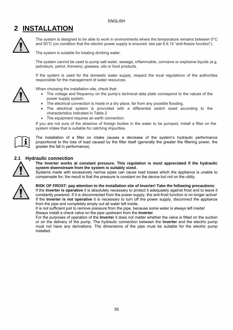
The system is designed to be able to work in environments where the temperature remains between 0°C and 50°C (on condition that the electric power supply is ensured: see par.6.6.14 “anti-freeze function”). The system is suitable for treating drinking water. The system cannot be used to pump salt water, sewage, inflammable, corrosive or explosive liquids (e.g. petroleum, petrol, thinners), greases, oils or food products. If the system is used for the domestic water supply, respect the local regulations of the authorities responsible for the management of water resources.
When choosing the installation site, check that: The voltage and frequency on the pump’s technical data plate correspond to the values of the
power supply system. The electrical connection is made in a dry place, far from any possible flooding. The electrical system is provvided with a differential switch sized according to the
characteristics indicated in Table 2 The equipment requires an earth connection.
If you are not sure of the absence of foreign bodies in the water to be pumped, install a filter on the system intake that is suitable for catching impurities.
The installation of a filter on intake causes a decrease of the system’s hydraulic performance proportional to the loss of load caused by the filter itself (generally the greater the filtering power, the greater the fall in performance).
2.1 Hydraulic connection
The Inverter works at constant pressure. This regulation is most appreciated if the hydraulic system downstream from the system is suitably sized. Systems made with excessively narrow pipes can cause load losses which the appliance is unable to compensate for; the result is that the pressure is constant on the device but not on the utility.
RISK OF FROST: pay attention to the installation site of Inverter! Take the following precautions: If the Inverter is operative it is absolutely necessary to protect it adequately against frost and to leave it constantly powered. If it is disconnected from the power supply, the anti-frost function is no longer active! If the Inverter is not operative it is necessary to turn off the power supply, disconnect the appliance from the pipe and completely empty out all water left inside. It is not sufficient just to remove pressure from the pipe, because some water is always left inside! Always install a check valve on the pipe upstream from the Inverter. For the purposes of operation of the Inverter it does not matter whether the valve is fitted on the suction or on the delivery of the pump. The hydraulic connection between the Inverter and the electric pump must not have any derivations. The dimensions of the pipe must be suitable for the electric pump installed.

ENGLISH
56
2.1.1 Single pump installation Figure 1 shows a schematic layout of the hydraulic installation of a pump with inverter.
Figure 1: Hydraulic installation
2.1.2 Multipump installation Our systems allow the possibility of creating multipump booster sets with coordinated control of all the inverters. The maximum number of elements that can be connected to create a multipump system is 8. To make use of the coordinated control function (multi-inverter) it is also necessary to make the required electrical connections to put the inverters in communication with one another see par. 2.3.6. A multipump system is used mainly for: • Increasing hydraulic performance in comparison with a single device. • Ensuring continuity of operation in the event of a device developing a fault. • Sharing out the maximum power.
The system is created in a similar way to the single pump system: each pump has its own delivery to its own inverter and the hydraulic outputs of the inverter all flow into a single manifold. The manifold must be correctly sized to support the flow created by the pumps that you want to use. The hydraulic plant must be created as symmetrically as possible to obtain a hydraulic load uniformly distributed over all the pumps. The pumps must all be the same and the inverters must all be of the same identical model, connected to each other in a multi-inverter configuration, see par. 2.1.2
2.2 Electrical connections The inverter is equipped with cables for the power supply and for the pump, indicated respectively with the labels LINE and PUMP.
The internal electrical connections are accessible by removing the 4 screws on the cover. The internal terminal boards have the same words LINE and PUMP applied on the cables.
Parts that make up the system 1 Expansion vessel
2 Pressure gauge
3, 12 Non‐return valve
4, 11 Ball valve
5, 9 Coupling with rapid inlet
6 Electropump connection
7 Line connection
8 Inverter
10 Filter
13 Pump

ENGLISH
57
Before performing any installation or maintenance operation, disconnect the inverter from the electrical mains and wait for at least 15 minutes before touching internal parts Ensure that the voltage and frequency values on the inverter data plate correspond to those of the power mains.
To improve the immunity to any noise radiated towards other equipment we recommend using separate ducts for the inverter supply cables. The installer shall be responsible for checking that the electric power supply system is fitted with an efficient earthing system according to the regulations in force.
Ensure that all the terminals are fully tightened, paying particular attention to the earth terminal. Also ensure that the cable clamps are fully secured to guarantee IP55 protection rating. Check that all the connecting cables are in perfect condition, with the external sheathing unbroken. The motor of the installed electric pump must comply with the data in Table 2.
Incorrect connection of the earth lines to a terminal other than the earth terminal may cause irremediable damage to the whole appliance!
Incorrect connection of the power supply line on output terminals intended for the load may cause irremediable damage to the whole appliance!
2.2.1 Pump connection for M/T and T/T models
The output for the electropump is available on the three-phase cable + earth indicated with the PUMP label. The motor of the installed electropump must be of the three-phase type with voltage 220-240V for type M/T and 380-480V for type T/T. To make the correct type of connection of the motor windings, follow the indications on the data plate or on the terminal board of the electropump.
2.2.2 Pump connection for M/M models The output for the electropump is available on the single-phase cable + earth indicated with the PUMP label. Type DV inverters can be connected to motors with power supply 110-127V oppure 220-240V. In order to use the voltage 220-240V to control the motor in a DV inverter, it is necessary to use a power supply with the same voltage.
For all M/M inverters size 11 and 14 A, ensure that the voltage of the motor used has been correctly configured, see par. 5.2.5.
M/M inverters size 8.5 A can be connected only to electropumps with a 230V single-phase motor.
2.3 CONNECTION TO THE POWER SUPPLY LINE
CAUTION: The line voltage may change when the electrical pump is started up by the inverter. The voltage may be subject to variations according to other devices connected, and the quality of the line.
ATTENTION: The protective circuit breaker and the power cables of the inverter and of the pump must be sized according to the system. The differential switch for protecting the system must be correctly sized according to the characteristics indicated in Table 2. For M/T and M/M inverters it is recommended to use a type F differential switch protected against sudden tripping. For T/T inverters it is recommended to use a type B differential switch protected against sudden tripping.
If the instructions supplied in this manual are in contrast with the regulations in force the regulations must be considered as valid
In the case of extensions to the inverter cables, for example for power supply to submersed electric pumps, if there is electromagnetic disturbance, the following is recommended: Check earthing and if necessary add an earthing device in the immediate vicinity of the Inverter. Embed the cables. Use shielded cables. Install the DAB Active Shield device.

ENGLISH
58
For correct operation the mains filter must be installed close to the Inverter!
2.3.1 Connection to the power supply for M/T and M/M models
The relative line specifications must correspond to those shown in Table 2.
The section, type and laying of cables for inverter power supply and electric pump connections must be selected in compliance with current standards. Table 3 provides indications on the cable section to be used. The table refers to cables in PVC with 3-core cable (phase neutral + earth)with the minimum recommended section based on the current and length of cable.
Power cable section in mm² Data for 3-core PVC cables (phase + neutral + earth)
10 m 20 m 30 m 40 m 50 m 60 m 70 m 80 m 90 m 100 m 120 m 140 m 160 m 180 m 200 m 4 A 1,5 1,5 1,5 1,5 2,5 2,5 2,5 2,5 4 4 4 6 6 6 10 8 A 1,5 1,5 2,5 2,5 4 4 6 6 6 10 10 10 10 16 16 12 A 1,5 2,5 4 4 6 6 10 10 10 10 16 16 16 16 A 2,5 2,5 4 6 10 10 10 10 16 16 16 20 A 4 4 6 10 10 10 16 16 16 16 24 A 4 4 6 10 10 16 16 16 28 A 6 6 10 10 16 16 16
Table 3: Section of power cables for M/M and M/T inverters
The current supply to the inverter can generally by estimated (with a relative safety margin) at 2.5 times the current absorbed by the three-phase pump. For example, if the pump connected to the inverter absorbs 10A per phase, the inverter power supply cables should be sized for 25A. Although the inverter is already equipped with internal safety devices, the installation of a suitably sized thermal magnetic circuit breaker is recommended.
2.3.2 Connection to the power supply for T/T models
The relative line specifications must correspond to those shown in Table 2. The section, type and laying of cables for inverter power supply and electric pump connections must be selected in compliance with current standards. Table 4 provides indications on the cable section to be used. The table refers to cables in PVC with 4 wires (3 phases+earth) with the minimum recommended section based on the current and length of cable.
Cable section in mm² Data for 4-core PVC cables (3 phases + earth))
10 m 20 m 30 m 40 m 50 m 60 m 70 m 80 m 90 m 100 m 120 m 140 m 160 m 180 m 200 m 4 A 1,5 1,5 1,5 1,5 1,5 1,5 1,5 1,5 2,5 2,5 2,5 2,5 4 4 4 8 A 1,5 1,5 1,5 1,5 2,5 2,5 2,5 4 4 4 6 6 6 10 10 12 A 1,5 1,5 2,5 2,5 4 4 4 6 6 6 10 10 10 10 16 16 A 2,5 2,5 2,5 4 4 6 6 6 10 10 10 10 16 16 16 20 A 2,5 2,5 4 4 6 6 10 10 10 10 16 16 16 16 16 24 A 4 4 4 6 6 10 10 10 10 16 16 16 16 16 16 28 A 6 6 6 6 10 10 10 10 16 16 16 16 16 16 16 32 A 6 6 6 6 10 10 10 16 16 16 16 16 16 16 16 36 A 10 10 10 10 10 10 16 16 16 16 16 16 16 16 16 40 A 10 10 10 10 10 16 16 16 16 16 16 16 16 16 16 44 A 10 10 10 10 10 16 16 16 16 16 16 16 16 16 16 48 A 10 10 10 10 16 16 16 16 16 16 16 16 16 16 16 52 A 16 16 16 16 16 16 16 16 16 16 16 16 16 16 16 56 A 16 16 16 16 16 16 16 16 16 16 16 16 16 16 16 60 A 16 16 16 16 16 16 16 16 16 16 16 16 16 16 16
Table 4: Section of 4-wire cable (3 phases + earth)

ENGLISH
59
The current supply to the inverter can normally be calculated (taking a safety margin into account) as 1/8 of the current absorbed by the pump. Although the inverter is already equipped with internal safety devices, the installation of a suitably sized thermal magnetic circuit breaker is recommended. If the entire power range available is used, for specific information on the current to be used when choosing cables and the thermal magnetic circuit breaker, refer to Table 4.
2.3.3 Connection of user inputs In inverters type M/T and T/T, the inputs can be switched on using either direct current or alternating current at 50-60 Hz. In type M/M the input can be activated only with a clean contact inserted between the two pins. The wiring diagram and the electrical characteristics of the inputs are shown below.
Wiring diagram of user inputs Type of inverter
Name of connector
Pin Use
M/T J6
1 Power supply terminal: + 12V DC – 50 mA 2 Connection terminal input I3 3 Connection terminal input I2 4 Common connection terminal I3 – I2 5 Connection terminal input I1 6 Common connection terminal I1 7 Connection terminal: GND
T/T J7
1 Power supply terminal: + 12V DC – 50 mA 2 Connection terminal input I3 3 Connection terminal input I2 4 Common connection terminal I3 – I2 5 Connection terminal input I1 6 Common connection terminal I1 7 Connection terminal: GND
M/M J2 1 Connection terminal input I1 2 Connection terminal: GND
Table 5: Input connection

ENGLISH
60
Control with clean contact Control with external voltage
Figure 2: Input connection
Ex. Use of IN 1
When IN 1 is activated the pump blocks and the “F1” signal is given
ex. IN 1 could be connected to a
float
Ex. Use of IN 2
When IN 2 is activated the regulating pressure becomes “P1”
(switching active setpoint:
SP or P1)
Ex. Use of IN 3
When IN 3 is activated the pump blocks and the “F3” signal is given
ex. IN 3 could be connected to a
safety pressure switch with manual reset
Power supply direct voltage ( Max. 36V) or
alternating voltage (Max. 24Vrms)
Power supply direct voltage ( Max. 36V) or
alternating voltage (Max. 24Vrms)
Power supply direct voltage ( Max. 36V) or
alternating voltage (Max. 24Vrms)
Clean contact
Jumper
Clean contact
Jumper
Clean contact
1
2
3
4
5
6
7
1
2
3
4
5
6
7
1
2
3
4
5
6
7
1
2
3
4
5
6
7
AC/DC
1
2
3
4
5
6
7
AC/DC
1
2
3
4
5
6
7
AC/DC
M/T ‐> J6 T/T ‐> J7
Jumper
M/T ‐> J6 T/T ‐> J7
M/T ‐> J6 T/T ‐> J7
M/T ‐> J6 T/T ‐> J7
M/T ‐> J6 T/T ‐> J7
M/T ‐> J6 T/T ‐> J7
ENGLISH
61
Table 6: Input specifications
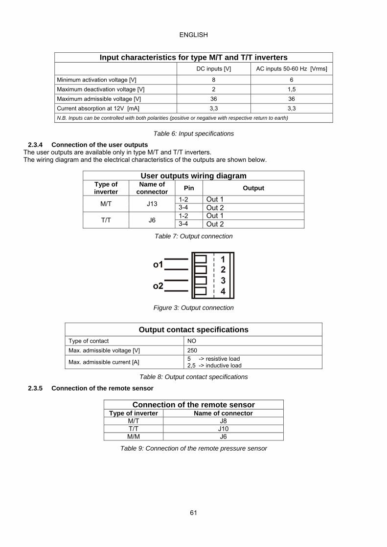
2.3.4 Connection of the user outputs The user outputs are available only in type M/T and T/T inverters. The wiring diagram and the electrical characteristics of the outputs are shown below.
User outputs wiring diagram Type of inverter
Name of connector
Pin Output
M/T J13 1-2 Out 1 3-4 Out 2
T/T J6 1-2 Out 1 3-4 Out 2
Table 7: Output connection
Figure 3: Output connection
Output contact specifications Type of contact NO
Max. admissible voltage [V] 250
Max. admissible current [A] 5 -> resistive load 2,5 -> inductive load
Table 8: Output contact specifications
2.3.5 Connection of the remote sensor
Connection of the remote sensor Type of inverter Name of connector
M/T J8 T/T J10 M/M J6
Table 9: Connection of the remote pressure sensor
Input characteristics for type M/T and T/T inverters DC inputs [V] AC inputs 50-60 Hz [Vrms]
Minimum activation voltage [V] 8 6
Maximum deactivation voltage [V] 2 1,5
Maximum admissible voltage [V] 36 36
Current absorption at 12V [mA] 3,3 3,3
N.B. Inputs can be controlled with both polarities (positive or negative with respective return to earth)
ENGLISH
62
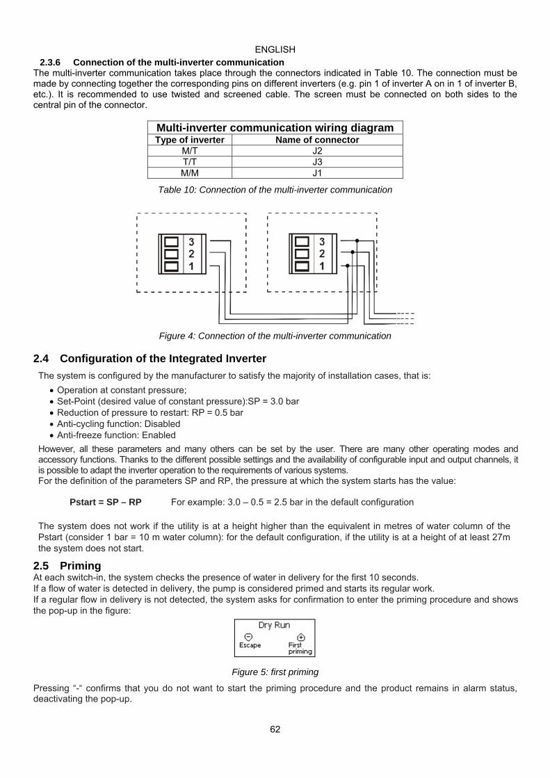
2.3.6 Connection of the multi-inverter communication The multi-inverter communication takes place through the connectors indicated in Table 10. The connection must be made by connecting together the corresponding pins on different inverters (e.g. pin 1 of inverter A on in 1 of inverter B, etc.). It is recommended to use twisted and screened cable. The screen must be connected on both sides to the central pin of the connector.
Multi-inverter communication wiring diagram Type of inverter Name of connector
M/T J2 T/T J3 M/M J1
Table 10: Connection of the multi-inverter communication
Figure 4: Connection of the multi-inverter communication
2.4 Configuration of the Integrated Inverter
The system is configured by the manufacturer to satisfy the majority of installation cases, that is:
Operation at constant pressure; Set-Point (desired value of constant pressure):SP = 3.0 bar Reduction of pressure to restart: RP = 0.5 bar Anti-cycling function: Disabled Anti-freeze function: Enabled
However, all these parameters and many others can be set by the user. There are many other operating modes and accessory functions. Thanks to the different possible settings and the availability of configurable input and output channels, it is possible to adapt the inverter operation to the requirements of various systems. For the definition of the parameters SP and RP, the pressure at which the system starts has the value:
Pstart = SP – RP For example: 3.0 – 0.5 = 2.5 bar in the default configuration
The system does not work if the utility is at a height higher than the equivalent in metres of water column of the Pstart (consider 1 bar = 10 m water column): for the default configuration, if the utility is at a height of at least 27m the system does not start.
2.5 Priming At each switch-in, the system checks the presence of water in delivery for the first 10 seconds. If a flow of water is detected in delivery, the pump is considered primed and starts its regular work. If a regular flow in delivery is not detected, the system asks for confirmation to enter the priming procedure and shows the pop-up in the figure:
Figure 5: first priming
Pressing “-“ confirms that you do not want to start the priming procedure and the product remains in alarm status, deactivating the pop-up.
ENGLISH
63
Pressing “+” starts the priming procedure: the pump starts and remains on for a maximum time of 2 minutes during which the safety block for dry operation is not tripped. As soon as the product detects a regular flow in delivery, it leaves the priming procedure and starts its regular operation. If the system is still not primed after 2 minutes of the procedure, the inverter stops the pump and the display reproposes the same water lack message, allowing the procedure to be repeated.
Prolonged dry operation of the electropump may cause damage to the pump.
2.6 Operation
Once the electropump is primed, the system starts regular operation according to the configured parameters: it starts automatically when the tap is turned on, supplies water at the set pressure (SP), keeps the pressure constant even when other taps are turned on, stops automatically after time T2 once the switching off conditions are reached (T2 can be set by the user, factory value 10 sec).
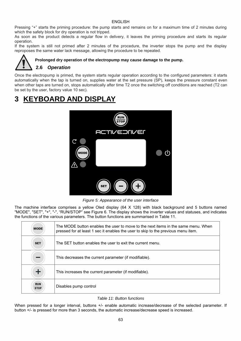
3 KEYBOARD AND DISPLAY
Figure 5: Appearance of the user interface
The machine interface comprises a yellow Oled display (64 X 128) with black background and 5 buttons named "MODE", "SET", "+", "-", “RUN/STOP” see Figure 6. The display shows the inverter values and statuses, and indicates the functions of the various parameters. The button functions are summarised in Table 11.
The MODE button enables the user to move to the next items in the same menu. When pressed for at least 1 sec it enables the user to skip to the previous menu item.
The SET button enables the user to exit the current menu.
This decreases the current parameter (if modifiable).
This increases the current parameter (if modifiable).
Disables pump control
Table 11: Button functions
When pressed for a longer interval, buttons +/- enable automatic increase/decrease of the selected parameter. If button +/- is pressed for more than 3 seconds, the automatic increase/decrease speed is increased.

ENGLISH
64
When the button + or – is pressed, the selected value is modified and saved immediately on the permanent memory (EEprom). Unit shutdown in this phase, even if inadvertent, does not cause loss of the set parameter. The SET button is only used to exit the current menu and is not used to save any changes. Only in some special cases described in 6 some values are implemented by pressing "SET" or "MODE".
3.1 Menus The complete structure of all menus and relative items is shown in Table 13.
3.2 Access to menus From all the menus you can access the other menus by a combination of keys. From the main menu you can also access the other menus from the drop-down menu.
3.2.1 Direct access with button combinations The menu is accessed directly by pressing the relative combination of buttons simultaneously (for example MODE SET to enter the Setpoint menu) and the MODE button can be used to scroll through the various items. Table 12 shows the menus accessible via button combinations.
MENU NAME DIRECT ACCESS BUTTONS PRESS-AND-HOLD TIME
User On release of button
Monitor 2 Sec
Setpoint 2 Sec
Manual 3 Sec
Installer 3 Sec
Technical assistance 3 Sec
Restore default settings
2 Sec on power-up of unit
Reset 2 Sec
Table 12: Access to menus

ENGLISH
65
Reduced menu ( visible ) Extended menu (direct access or password )
Main Menu
User Menu mode
Monitor Menuset-minus
Setpoint Menumode-set
Manual Menuset-plus-minus
Installer Menu mode-set-minus
Tech. Ass. Menu
mode-set-plus MAIN
(Main Page) FR
Rotation frequency
VF Flow display
SPSetpoint pressure
FPManual
mod. frequency
RC Rated current
TBWater lack
blocking time Menu Selection VP
Pressure TE
Heat sink Temperature
P1Auxiliary
pressure 1
VPPressure
RT*
Direction of rotation
T1Switch-off time after low press.
C1 Pump phase
current
BT Board
Temperature
P2*
Auxiliary pressure 2
C1Pump phase
current
FN Rated frequency
T2Delay on switch-
off
PO Power
absorbed by the pump
FF Fault & Warning
Log
P3*
Auxiliary pressure 3
POPower absorbed
by the pump
UN+
Rated voltage GP
Proportional gain
PI Power
histogram
CT Contrast
RT*
Direction of rotation
OD Type of system
GIIntegral gain
SM System Monitor
LA Language
VFFlow display
RP Decrease press.
to restart
FSMaximum frequency
VE HW and SW Information
HO Hours of operation
AD Address
FLMinimum frequency
EN Energy meter
PR Remote pressure
sensor
NAActive Inverters
SN Number of starts
MS Measuring
system
NCMax
simultaneous inverters
SX Max Setpoint
ICInverter config
ETMax exchange
time CF
Carrier AC
Acceleration AY
Anticycling AE
Antiblocking AF
AntiFreeze I1
Input 1 function I2*
Input 2 function I3*
Input 3 function O1*
Output 1 function O2*
Output 2 function SF+
Starting frequency
ST+
Starting time
FWFirmware update

ENGLISH
66
RFReset
fault & warning PW
Change Password
*Parameters present only on type M/T and T/T inverters + Parameters present only on type M/M inverters
Table 13: Menu structure
Key
Identification colours Modification of multi inverter unit parameters
Series of sensitive parameters. These parameters must be aligned to enable start-up of the multi-inverter system. Modification of one of these parameters on any inverter will automatically align all other inverters without the need for any command.
Parameters that enable facilitated alignment from a single inverter, transferring data to all others. It is admissible that these differ between inverters.
Series of parameters that can be aligned in broadcast mode by one inverter only.
Read-only parameters.
3.2.2 Access by name via drop-down menus The menus are selected via their specific name. The user accesses menu selection via the main menu, by pressing button + or –. The menu selection pages contains all the names of menus accessible, one of which is highlighted with a bar (see Figure 7). The buttons + and - can be used to move the highlighter bar to the menu required, which is then entered by pressing SET.
Figure 6: Drop-down menu selection
The menus available are MAIN, USER, and MONITOR; after access to these, a fourth FULL MENU is displayed, to enable full display of the menus selected. On selection of EXTENDED MENU a pop-up window is displayed, requesting entry of a PASSWORD. The PASSWORD is the same as the key combination used for direct access and enables the user to expand display of the menus from the password-protected menu to all those with lower priority. The menu order is: User, Monitor, Setpoint, Manual, Installer, Technical Assistance. On entry of a password, the unlocked menus remain available for 15 minutes or until disabled manually by means of the menu command “Hide advanced menus” which appears on selection of menus after entry of the password. Figure 8 shows the functional scheme for menu selection. The centre of the page shows the menus; the user can access these from the right using the button combinations, or from the left by means of the drop-down menu selection system.

ENGLISH
67
Figure 7: Optional menu access scheme
3.3 Structure of menu pages When switching on, some introductory pages are displayed, followed by a main menu. The name of each menu is always displayed at the top of the screen. The main menu always displays the following items: Status: operating status (e.g. standby, go, Fault, input functions) Frequency: value in [Hz] Pressure: value in [bar] or [psi] depending on the set unit of measurement. If an event occurs, the following may be displayed: Fault messages Warning messages Messages on functions associated with inputs Special icons The error or status conditions visible in the main menu are listed in Table 14.
Error and status conditions visible in the main menu
Identifier Description
GO Electric pump ON SB Electric pump OFF
PH Cutout due to pump overheating BL Block due to water failure LP Block due to low power supply voltage HP Block due to high internal power supply voltage EC Block due to incorrect setting of rated current OC Block due to current overload on electric pump motor OF Block due to current overload on final stages of output SC Block due to short circuit on output phases OT Block due to overheating of final power stages OB Block due to overheating of printed circuit

ENGLISH
68
Table 14: Error status messages on main page The other menu pages vary according to the associated functions, and are described below according to the type of specification or setting. After entering any one of the menus, the lower section of the page always shows a summary of the main operating parameters (operating status or possible fault status, applied frequency and pressure). This enables a constant overview of the main machine parameters.
Figure 8: Menu parameter display
Table 15: Status bar indications
The following can be shown on parameter display pages: numerical values and unit of measurement of current item, values of other parameters related to setting of current item, graphic bar, lists; see Figure 9. 3.4 Parameter setting block via Password The inverter is equipped with a password protection system. If a password is set, the inverter parameters will be accessible and visible, but it will not be possible to change them, except the parameters SP, P1, P2, P3, RP, FP, LA, CT. In turn, the parameters SP, P1, P2, P3 are limited by SX (SX is subordinate to the password). The password management system is located in the menu “technical assistance” and is managed by means of parameter PW, see paragrap 6.6.20 .
BP1 Blockage due to reading error on the internal pressure sensor
BP2 Blockage due to reading error on the remote pressure sensor NC Pump not connected F1 Float function status/alarm F3 System disable function status/alarm F4 Low pressure signal function status/alarm P1 Operating status with auxiliary 1 pressure P2 Operating status with auxiliary 2 pressure P3 Operating status with auxiliary 3 pressure
Com. icon with number Operating status in multi inverter communication with specified address
Com. icon with E Error status in communication of multi inverter system
Ei Blockage due to i-th internal error
Vi Blockage due to i-th internal voltage out of tolerance
EY Block for cyclicality abnormal detected on the system EE Writing and rereading on EEPROM of the factory settings
WARN. Low voltage
Warning due to power supply voltage failure
Status bar indications at the bottom of each page
Identifier Description GO Electric pump ON SB Electric pump OFF
FAULT Presence of error that prevents control of the electric pump
ENGLISH
69
3.5 Enabling and disabling the motor Once the first configuration has been performed with the wizard, the [RUN/STOP] key can be used to disable and re-enable the motor control. If the inverter is running (green led ON yellow led ON) or is stopped (green led OFF yellow led ON), the motor control can be disabled by pressing the [RUN/STOP] key. When the inverter is disabled, the yellow led blinks and the green led is always off. To re-enable pump control it is sufficient to press the [RUN/STOP] key again. The [RUN/STOP] key can only disable the inverter, it is not a start command. The running status is decided only by the regulating algorithms or by the inverter functions. The key function is active on all the pages.
4 MULTI INVERTER SYSTEM
4.1 Introduction to multi inverter systems A multi inverter system comprises a pump set made up of a series of pumps with delivery outlets all conveying to a single manifold. Each pump of the set is connected to its own inverter and the various inverters communicate via a special connection. The maximum number of pump-inverter elements possible in a group is 8. A multi inverter system is mainly used toper:
Increase the hydraulic performance with respect to a single inverter Ensure operation continuity in the event of a fault on a pump or inverter Partition maximum power
4.2 Setting up a multi inverter system The pumps, motors and inverters in the system must be identical versions. The hydraulic system must be as symmetric as possible in order to achieve a hydraulic load evenly distributed on all the pumps. The pumps must all be connected to a single delivery manifold.
Since the pressure sensors are each inside the plastic body, you must take care not to place non-return valves between one inverter and another, otherwise the inverters may read different pressures from each other and give as a result a false mean value and an abnormal regulation.
For the operation of the booster set, the inverters must be of the same type and model; they must also be the same for each inverter-pump pair:
type of pump and motor hydraulic connections rated frequency minimum frequency maximum frequency
4.2.1 Communication The inverters communicate with each other through the dedicated 3-wire connection. For the connection, see par. 2.3.6.
4.2.2 Remote sensor in multi-inverter systems To use the pressure control functions with a remote sensor, the sensor can be only 1 connected to one of the inverters present. Even several remote pressure sensors can be connected, up to one for each inverter. If several sensors are present, the regulating pressure will be the mean of all the connected sensors. To ensure that the remote pressure sensor can be visible by the other inverters, the multi-inverter communication must be correctly connected and configured on all the inverters, and the inverter to which it is connected must be On.
4.2.3 Connection and setting of the optical coupling inputs The inputs of the inverter are photocoupled (see para. 2.3.3 and 6.6.15) this means that galvanic separation of the inputs from the inverter is guaranteed, to enable the functions for the float, auxiliary pressure, system disable, and low pressure on intake. The functions are indicated respectively by the messages F1, Paux, F3, F4. If activated, the Paux function boosts the pressure in the system to the set pressure, see par. 6.6.15.3. The functions F1, F3, F4 stop the pump for 3 different reasons, see par. 6.6.15.2, 6.6.15.4, 6.6.15.5. When using a multiple inverter system, the inputs must be used with the following settings:
the contacts that perform the auxiliary pressures must be connected in parallel on all the inverters so that the same signal arrives on all the inverters.

ENGLISH
70
the contacts that perform the functions F1, F3, F4 may be connected either with independent contacts for each inverter, or with only one contact connected in parallel on all the inverters (the function is activated only on the inverter at which the command arrives).
The parameters for setting the inputs I1, I2, I3, I4 are part of the sensitive parameters, so setting one of these on any inverter means that they are automatically aligned on all the inverters. As the setting of the inputs not only selects the function, but also the type of polarity of the contact, the function associated with the same type of contact will perforce be found on all the inverters. For the above reason, when using independent contacts for each inverter (as is possible for the functions F1, F3, F4), these must all have the same logic for the various inputs with the same name; that is, for the same input, either normally open contacts are used for all the inverters or normally closed ones.
4.3 Multi inverter operating parameters The parameters displayed on the menu, in a multi-inverter configuration, can be classed as follows:
Read-only parameters Local parameters Multi inverter system configuration parameters in turn divided as
o Sensitive parameters o Parameters with optional alignment
4.3.1 Parameters related to multi inverter systems
4.3.1.1 Local parameters These are parameters that can differ from one inverter to another and in some cases actually need to be different. For these parameters, automatic alignment of inverter configuration is not admitted. In the case of manual assignment of addresses, these must all be different. List of local parameters for inverters:
CT Contrast FP Test frequency in manual mode RT Direction of rotation AD Address IC Reserve configuration RF Fault and warning reset
4.3.1.2 Sensitive parameters These are parameters that must be aligned on the entire series for control purposes. List of sensitive parameters:
SP Setpoint pressure T1 Shutdown time after low pressure signal P1 Input 1 auxiliary pressure T2 Shutdown time P2 Input 2 auxiliary pressure GI Integral gain P3 Input 3 auxiliary pressure GP Proportional gain SX Maximum setpoint FL Minimum Frequency FN Nominal frequency I1 Input 1 setting RP Pressure drop for restart I2 Input 2 setting ET Exchange time I3 Input 3 setting AC Acceleration OD Type of system NA Number of active inverters PR Remote pressure sensor NC Number of simultaneous inverters AY Anti cycling CF Carrier frequency PW Password Settings TB Dry run time
Automatic alignment of sensitive parameters When a multi inverter system is detected, the unit checks for consistency of the set parameters. If the sensitive parameters are not aligned on all inverters, the display of each inverter shows a message requesting whether to transfer the configuration of the specific inverter to the entire system. On acceptance, the sensitive parameters on the inverter where confirmation is given are distributed to all other inverters in the series. If there are configurations incompatible with the system, the configuration cannot be aligned from these inverters. During normal operation, modification of a sensitive parameter on an inverter will cause automatic alignment of the parameter on all other inverters without any request for confirmation.
Automatic alignment of sensitive parameters has no effect on all other types of parameter .

ENGLISH
71
In the particular case of inserting an inverter with default settings in the series (in the case of an inverter which replaces an existing model or an inverter with restored factory settings), if the configurations applied, with the exception of factory settings, are consistent, the inverter with the factory settings will automatically take on the sensitive parameters of the series.
4.3.1.3 Parameters with optional alignment These are the parameters that are admissible even if not aligned with other inverters. Each time these parameters are modified, when SET or MODE is pressed, the request is displayed whether to modify the entire communicating inverter series. In this way if the series has all the same settings, the same data does not need to be set on all inverters. List of parameters with optional alignment: LA Language RC Rated current MS Measurement system FS Maximum frequency UN Pump rated voltage SF Starting frequency ST Starting time AE Anti-blocking AF Anti freeze O1 Output 1 function O2 Output 2 function
4.4 Initial start-up of multiple inverter system Make electrical and hydraulic connections of the entire system as described in para 2.2 and para 4.2. Switch on one inverter at a time and configure the parameters as described in chapter 5 taking care that when turning on one inverter, all others are switched off. After configuring all inverters individually, all can be switched on simultaneously.
4.5 Multi-inverter settings When a multi inverter system is switched on, the addresses are assigned automatically and, by means of an algorithm, an inverter is nominated as the settings leader. The leader decides on the frequency and order of start-up of each inverter in the series. The settings mode is sequential (inverters start one at a time). When start-up conditions are enabled, the first inverter starts, and when this reaches maximum frequency, the next one starts, and so on. The order of start-up is not necessarily ascending according to the machine address, but depends on the hours of operation; see ET: Tempo di scambio par. 6.6.9. When the minimum frequency FL is used, and there is only one inverter operative pressure surges may occur. Depending on the case, pressure surges may be inevitable and may occur at the minimum frequency when this value, in relation to the hydraulic load, causes a pressure level greater than the required value. On multi inverter systems, this problem remains limited to the first pump that is started up, as on the subsequent pumps the situation is as follows: when the previous pump reaches the maximum frequency, the next one starts up at the minimum frequency to then reach the maximum frequency. When the frequency of the pump at maximum is reduced (obviously through to the minimum frequency limit) the pump activation overlaps, which while observing minimum frequency rates, does not cause pressure surges.
4.5.1 Assigning the start-up order Each time the system is activated, each inverter is associated a starting order. This setting establishes the order of inverter start-up. The starting order is modified during use according to requirements, by the two following algorithms:
Reaching of maximum operating time Reaching of maximum inactivity time
4.5.1.1 Maximum operating time According to parameter ET (maximum operating time), each inverter has an hour counter, and the starting order is updated on the basis of these values according to the following algorithm:
- if at least half of the value ET is exceeded, priority is changed on the first shutdown of the inverter (switch to standby).
- if the value ET is reached without stopping, the inverter stops unconditionally and this sets to the minimum restart priority (switch during operation).
If parameter ET (maximum working time) is set to 0, exchange occurs on each restart.
See ET: Tempo di scambio par. 6.6.9.
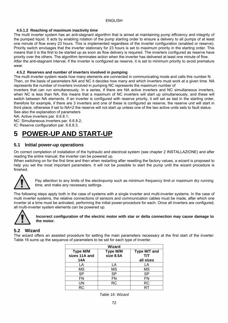
ENGLISH
72
4.5.1.2 Reaching of maximum inactivity time
The multi inverter system has an anti-stagnant algorithm that is aimed at maintaining pump efficiency and integrity of the pumped liquid. It acts by enabling rotation of the pump starting order to ensure a delivery to all pumps of at least one minute of flow every 23 hours. This is implemented regardless of the inverter configuration (enabled or reserve). Priority switch envisages that the inverter stationary for 23 hours is set to maximum priority in the starting order. This means that it is the first to be started up as soon as flow delivery is required. The inverters configured as reserve have priority over the others. The algorithm terminates action when the inverter has delivered at least one minute of flow. After the anti-stagnant interval, if the inverter is configured as reserve, it is set to minimum priority to avoid premature wear.
4.5.2 Reserves and number of inverters involved in pumping The multi inverter system reads how many elements are connected in communicating mode and calls this number N. Then, on the basis of parameters NA and NC it decides how many and which inverters must work at a given time. NA represents the number of inverters involved in pumping NC represents the maximum number of inverters that can run simultaneously. In a series, if there are NA active inverters and NC simultaneous inverters, when NC is less than NA, this means that a maximum of NC inverters will start up simultaneously, and these will switch between NA elements. If an inverter is configured with reserve priority, it will set as last in the starting order, therefore for example, if there are 3 inverters and one of these is configured as reserve, the reserve unit will start in third place; otherwise if set to NA=2 the reserve will not start up unless one of the two active units sets to fault status. See also the explanation of parameters NA: Active inverters par. 6.6.8.1; NC: Simultaneous inverters par. 6.6.8.2; IC: Reserve configuration par. 6.6.8.3.
5 POWER-UP AND START-UP
5.1 Initial power-up operations
On correct completion of installation of the hydraulic and electrical system (see chapter 2 INSTALLAZIONE) and after reading the entire manual, the inverter can be powered up. When switching on for the first time and then when restarting after resetting the factory values, a wizard is proposed to help you set the most important parameters. It will not be possible to start the pump until the wizard procedure is finished.
Pay attention to any limits of the electropump such as minimum frequency limit or maximum dry running time, and make any necessary settings.
The following steps apply both in the case of systems with a single inverter and multi-inverter systems. In the case of multi inverter systems, the relative connections of sensors and communication cables must be made, after which one inverter at a time must be activated, performing the initial power-procedure for each. Once all inverters are configured, all multi-inverter system elements can be powered up.
Incorrect configuration of the electric motor with star or delta connection may cause damage to the motor.
5.2 Wizard The wizard offers an assisted procedure for setting the main parameters necessary at the first start of the inverter. Table 16 sums up the sequence of parameters to be set for each type of inverter.
Wizard Type M/M
sizes 11A and 14A
Type M/M size 8.5A
Type M/T and T/T
all sizes LA LA LA MS MS MS SP SP SP FN FN FN UN RC RC RC RT
Table 16: Wizard

ENGLISH
73
During the procedure the [+] and [-] keys are used to set the various values. The [MODE] key is used to accept the set value and move on to the next step. If the mode key is held down for more than 1s, the wizard returns to the previous page.
5.2.1 Setting the language LA Select the menu language that you want to use. See par. 6.2.6
5.2.2 Setting the measurement system MS Set the display system of the measurement unit you want to use for the values on the display. See par. 6.5.9
5.2.3 Setting the pressure setpoint SP Set the system pressure setpoint value. See par. 6.3.1
5.2.4 Setting the rated frequency of the pump FN Select the rated frequency of the electropump that you want to use. The wizard measures the mains frequency entering the inverter and, based on this, proposes a value for FN. The user must set this value according to the recommendation of the electropump manufacturer. See par. 6.5.3
An incorrect configuration of the working frequency of the electropump may cause damage to the electropump and give rise to “OC” and “OF” errors.
5.2.5 Setting the rated voltage of the pump UN This parameter is present only on type M/M inverters, size 11 and 14 A. Select the rated voltage of the electropump that you want to use. The wizard measures the mains voltage entering the inverter and, based on this, proposes a value for UN. The user must set this value according to the recommendation of the electropump manufacturer. See par. 6.5.4
5.2.6 Setting the rated current RC Select the rated current value of the electropump that you want to use. See par. 6.5.1
An incorrect setting of RC can give rise to “OC” and “OF” errors and cause failed intervention of the overload protection, allowing a load beyond the safety threshold of the motor and causing damage to the motor.
5.2.7 Setting the direction of rotation RT This parameter is present in all sizes of type M/T and T/T inverters. When you come to the RT setting you must start the pump and check that its axis is turning in the correct direction. In this phase the RUN/STOP key is used to start and stop the pump. Pressing the key the first time starts the pump, the second time stops it. During this phase a maximum run time of 2 min is allowed, after which time it switches off automatically (similar to stopping with the RUN/STOP key). During this phase the + and – keys allow you to invert the direction of rotation of the motor. In case of a surface pump with visible direction of rotation:
start the pump, check the direction of rotation and change it if necessary, stop the pump, press mode to confirm the settings made and to start the application.
In case of a submerged pump: switch on a utility (do not change the utility until the end of the procedure), start the pump, make a note of the direction of rotation used and the frequency realised (parameter FR at top right of the
wizard screen 6/6), change the direction of rotation, make a note of the direction of rotation used and the frequency realised (parameter FR at top right of the
wizard screen 6/6), close the utility, evaluate the two cases examined and set the direction of rotation that gives the lower frequency FR, press mode to confirm the settings made and to start normal operation.
5.2.8 Setting other parameters After the initial start-up procedure, the other pre-set parameters can be modified as required, by accessing the relative menus and following the instructions for the specific parameters (see chapter 6). The most common parameters are: restart pressure, regulation gain values GI and GP, minimum frequency FL, water failure time TB, etc.
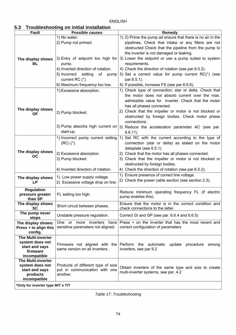
ENGLISH
74
5.3 Troubleshooting on initial installation Fault Possible causes Remedy
The display shows BL
1) No water. 2) Pump not primed. 3) Entry of setpoint too high for
pump. 4) Inverted direction of rotation. 5) Incorrect setting of pump
current RC (*). 6) Maximum frequency too low.
1) 2) Prime the pump ad ensure that there is no air in the pipelines. Check that intake or any filters are not obstructed Check that the pipeline from the pump to the inverter is not damaged or leaking.
3) Lower the setpoint or use a pump suited to system requirements.
4) Check the direction of rotation (see par.6.5.2). 5) Set a correct value for pump current RC(*) (see
par.6.5.1). 6) If possible, increase FS (see par.6.6.6).
The display shows OF
1) Excessive absorption.
2) Pump blocked.
3) Pump absorbs high current on
start-up.
1) Check type of connection; star or delta. Check that the motor does not absorb current over the max. admissible value for inverter. Check that the motor has all phases connected.
2) Check that the impeller or motor is not blocked or obstructed by foreign bodies. Check motor phase connections.
3) Reduce the acceleration parameter AC (see par. 6.6.11)
The display shows OC
1) Incorrect pump current setting (RC) (*).
2) Excessive absorption. 3) Pump blocked.
4) Inverted direction of rotation.
1) Set RC with the current according to the type of connection (star or delta) as stated on the motor dataplate (see 6.5.1)
2) Check that the motor has all phases connected. 3) Check that the impeller or motor is not blocked or
obstructed by foreign bodies. 4) Check the direction of rotation (see par.6.5.2).
The display shows LP
1) Low power supply voltage. 2) Excessive voltage drop on line.
1) Ensure presence of correct line voltage. 2) Check the power cable section (see section 2.3).
Regulation pressure greater
than SP FL setting too high.
Reduce minimum operating frequency FL (if electric pump enables this).
The display shows SC
Short circuit between phases. Ensure that the motor is in the correct condition and check connections to the latter.
The pump never stops
Unstable pressure regulation. Correct GI and GP (see par. 6.6.4 and 6.6.5)
The display shows: Press + to align this
config.
One or more inverters have sensitive parameters not aligned.
Press + on the inverter that has the most recent and correct configuration of parameters
The Multi-inverter system does not
start and says firmware
incompatible
Firmware not aligned with the same version on all inverters.
Perform the automatic update procedure among inverters, see par 9.2
The Multi-inverter system does not
start and says products
incompatible
Products of different type of size put in communication with one another.
Obtain inverters of the same type and size to create multi-inverter systems, see par. 4.2
*Only for inverter type M/T e T/T
Table 17: Troubleshooting

ENGLISH
75
6 KEY TO INDIVIDUAL PARAMETERS
6.1 User menu The USER MENU is accessed by pressing MODE (or via the selection menu by pressing + or - ). Within this menu, again by pressing MODE, the following values are displayed consecutively.
6.1.1 FR: Display of rotation frequency Current rotation frequency with electric pump is controlled, in [Hz].
6.1.2 VP: Display of pressure System pressure measured in [bar] or [psi] depending on measurement system used.
6.1.3 C1: Display of phase current
Phase current of electric pump in [A]. If the maximum allowed current is exceeded, the current value shown on the display will start to blink between normal display and reverse. This representation indicates a pre-alarm condition which foresees the probable tripping of the overload protection on the motor. In this case it is necessary to check the correct setting of the maximum current of the RC pump, see paragraph 6.5.1 and the electric pump connections.
6.1.4 PO: Display of the power delivered Power delivered to the electropump in [kW].
6.1.5 PI: Power histogram A histogram of the power delivered is displayed on 5 vertical bars. The histogram indicates how long the pump has been on at a given power level. On the horizontal axis are the bars at the various power levels; on the vertical axis, the time for which the pump has been on at the specific power level (% of the time with respect to the total). The resetting of the partial hour counter also resets the hour histogram.
Figure 9: Power histogram
6.1.6 SM: System monitor Displays the system status in the case of a multi-inverter installation. If there is no communication, an icon is displayed, showing communication absent or interrupted. If there are several interconnected inverters, an icon is shown for each. The icon bears the symbol of a pump with pump status indications below. Depending on operating status, the item in Table 18 is displayed.
System display
Status Icon Status information below icon
Inverter in run Symbol of pump running Frequency implemented on 3 digits Inverter in standby
Symbol of static pump SB
Inverter in fault Symbol of static pump F Inverter disabled
Symbol of static pump D
Table 18: Display of SM system monitor
If the inverter is configured as a reserve, the display remains similar to Table 18 with the difference that the top part of the icon depicting the motor appears coloured.
To reserve more space for the system display, the name of the parameter SM is not shown, but simply the text “system” below the menu name.
6.1.7 VE: Display of version Hardware and software version of the equipment.

ENGLISH
76
6.2 Monitor menu The MONITOR MENU is accessed from the main menu by pressing and holding the buttons “SET” and “-“ (minus) simultaneously for 2 seconds, or via the selection menu using buttons + or -. Within this menu, by pressing MODE, the following values are displayed consecutively.
6.2.1 VF: Flow display Displays the two possible statuses of the flow: “present” and “absent”. If the inverter is working in a multi-inverter system, the flow displayed represents the system flow. During multi-inverter operation, the local flow is indicated in the rectangle at bottom left with the letters “P” = present “A” = absent If the inverter is in single operation, it displays only the flow read by its own sensor.
6.2.2 TE: Display of final power stage temperature
6.2.3 BT: Display of electronic board temperature
6.2.4 FF: Display of fault log Chronological display of faults occurring during system operation. Tow numbers x/y are displayed below the symbol FF, which indicate respectively “x” for the fault displayed and “y” for the total number of faults present; an indication of the type of fault is displayed to the right. Buttons + and – can be used to scroll through the list of faults: press – to move back through the log through to the oldest fault present, or + to scroll forward to the most recent.
The faults are shown in chronological order, starting from the oldest x=1 to the most recent x=y. The maximum number of faults displayable is 64; after which the system overwrites the oldest versions in order. Next to the type of fault, the time of switching on also appears, relating to the time the fault occurred.
This menu item displays the fault list but does not enable reset. The list can only be cleared by means of the specific command in the item RF of the TECHNICAL ASSISTANCE MENU. Neither a manual reset or shutdown of the unit, or restored default settings will clear the fault log; only the above procedure will enable this.
6.2.5 CT: Display contrast This adjusts the display contrast.
6.2.6 LA: Language Display in one of the following languages:
1- Italian 2- English 3- French 4- German 5- Spanish 6- Dutch 7- Swedish 8- Turkish 9- Slovakian 10- Romanian 11- Czech 12- Polish 13- Portuguese 14- Finnish 15- Ukrainian 16- Russian 17- Greek 18- Arabic
6.2.7 HO: Operating hours Indicates, on two lines, the hours of inverter activation and pump operating hours.
6.2.8 EN: absorbed energy counter This indicates on two lines the total absorbed energy and the partial energy. The total energy is a number that always increases during the lifetime of the machine and can never be reset. The partial energy is an energy counter that can be reset by the user. The partial counter is reset by pressing the [-] key for 5 sec. The resetting of the partial hour counter also resets the hour histogram.

ENGLISH
77
6.2.9 SN: Number of starts Indicates the number of times the inverter has started the electropump.
6.3 Setpoint menu From the main menu, press and hold MODE and SET simultaneously until “SP” appears on display (or use the buttons + or – in the selection menu). Buttons + and – enable respectively to increase and decrease the system pressurisation value. To exit the current menu and return to the main menu, press SET.
This menu enables the user to set the system operating pressure. The regulating pressure can be set as indicated in table 2.
6.3.1 SP: Setting the setpoint pressure Pressure to apply to the system if the auxiliary pressure regulation functions are not active.
6.3.2 Auxiliary pressure settings The inverter can vary the set point pressure according to the status of the inputs. On type M/T and T/T inverters, up to 3 auxiliary pressures can be set for a total of 4 different set points. On type M/M inverters, one auxiliary pressure can be set for a total of 2 different set points. For the electrical connections, refer to paragraph 2.3.3, and for software settings, refer to paragraph 6.6.15.
If there are several auxiliary pressure functions active, associated with several inputs, the inverter applies the lowest pressure of all those activated.
6.3.2.1 P1: Auxiliary pressure 1 setting
Pressure to apply to the system if the auxiliary pressure function is activated on input 1.
6.3.2.2 P2: Auxiliary pressure 2 setting Pressure to apply to the system if the auxiliary pressure function is activated on input 2. Not available on type M/M inverters.
6.3.2.3 P3: Auxiliary pressure 3 setting Pressure to apply to the system if the auxiliary pressure function is activated on input 3. Not available on type M/M inverters.
The pump restart pressure depends both on the set pressure (SP, P1, P2, P3) and RP. RP expresses the reduction in pressure, with respect to "SP" (or an auxiliary pressure if activated), which generates pump start-up.
Exemple: SP = 3,0 [bar]; RP = 0,5 [bar]; no auxiliary pressure function active:
During normal operation, the system pressure is set at 3.0 [bar]. The electric pump is restarted when the pressure falls below 2.5 [bar].
Entry of an excessively high pressure setting (SP, P1, P2, P3) with respect to the pump output specifications, may cause false errors of water failure (BL); in this case lower the pressure setting or use a pump suited to system requirements.
6.4 Manual menu From the main menu, press and hold “SET" & “+” & “-“ simultaneously until “FP” appears on display (or use the buttons + or – in the selection menu). This menu enables the display and modification of various configuration parameters. The MODE button enables the user to scroll through the menu pages, while buttons + and – enable respectively to increase and decrease the value of the parameter concerned. To exit the current menu and return to the main menu, press SET.
In manual mode, regardless of the parameter on display, the following commands are enabled:
Temporary start-up of electric pump When the buttons MODE and - are pressed simultaneously, the pump is started up at the frequency FP and this operating status remains while the buttons are pressed. When the pump ON or pump OFF command is activated, the relative notification is shown on display. Pump start-up When the buttons MODE and + are pressed simultaneously for 2 seconds, the pump is started up at the frequency FP. This operating status remains until SET is pressed. When SET is pressed again, the user exits the manual mode menu. When the pump ON or pump OFF command is activated, the relative notification is shown on display. Inversion of direction of rotation

ENGLISH
78
When the buttons SET and - are pressed simultaneously for 2 seconds, the pump changes direction of rotation. The function is also enabled when the motor is running.
6.4.1 FP: Test frequency setting This displays the test frequency in [Hz] and enables modification by means of the buttons “+” and “-“. The default value is FN – 20% and can be set between 0 and FN.
6.4.2 VP: Display of pressure
System pressure measured in [bar] or [psi] depending on measurement system selected.
6.4.3 C1: Display of phase current Phase current of electric pump in [A]. If the maximum allowed current is exceeded, the current value shown on the display will start to blink between normal display and reverse. This representation indicates a pre-alarm condition which foresees the probable tripping of the overload protection on the motor. In this case it is necessary to check the correct setting of the maximum current of the RC pump, see paragraph 6.5.1 and the electric pump connections.
6.4.4 PO: Display of the power delivered Power delivered to the electropump in [kW].
6.4.5 RT: Setting the direction of rotation This parameter is present only on type M/T and T/T inverters. If the direction of pump rotation is incorrect, it can be inverted by changing this parameter. In this menu item, use buttons + and – to activate and display the two possible states “0” or “1”. The phase sequence is shown in the comment line on display. The function is also enabled when the motor is running. If it is not possible to see the direction of motor rotation after entering manual mode, proceed as follows:
o Start up the pump at frequency FP (pressing MODE and + or MODE + -) o Turn on a utility and check the pressure o Without changing collection, modify parameter RT and the pressure again. o The correct RT parameter is that which generates a higher pressure.
6.4.6 VF: Flow display See paragraph 6.2.1
6.5 Installer menu From the main menu, press and hold “MODE” & “SET” & “-“ simultaneously until “RC” appears on display (or use the buttons + or – in the selection menu). This menu enables the display and modification of various configuration parameters. The MODE button enables the user to scroll through the menu pages, while buttons + and – enable respectively to increase and decrease the value of the parameter concerned. To exit the current menu and return to the main menu, press SET.
6.5.1 RC: Electric pump rated current setting Rated current absorbed by the electropump in Ampere (A). Insert the absorption declared by the manufacturer on the data plate of the electropump. In the case of type M/T and T/T inverters, pay attention to the type of connection used for the windings. If the parameter entered is lower than the correct value, the error “OC" is displayed during operation as soon as the set current exceeds the current set value for a set time interval. If the parameter entered is higher than the correct value, the current sensitivity protection will trip inadvertently over the motor safety threshold.
6.5.2 RT: Setting the direction of rotation This parameter is present only on type M/T and T/T inverters. If the direction of pump rotation is incorrect, it can be inverted by changing this parameter. In this menu item, use buttons + and – to activate and display the two possible states “0” or “1”. The phase sequence is shown in the comment line on display. The function is also enabled when the motor is running. If it is not possible to see the direction of motor rotation, proceed as follows:
o Turn on a utility and check the frequency. o Without changing collection, modify parameter RT and check the FR frequency again. o The correct RT parameter is that which requires, compared to collection, a lower frequency FR.
CAUTION: on some electric pumps, it may occur that there is little difference in frequency in the two cases, and it is therefore difficult to understand which is the correct direction of rotation. In these cases, repeat the test described above, but rather than checking frequency, attempt to check the phase current absorption (parameter C1 in the user menu). The correct RT parameter is that which requires, compared to collection, a lower phase current C1.
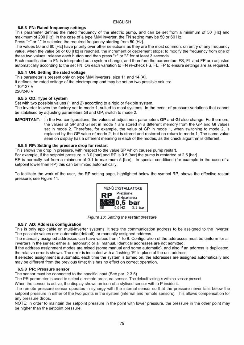
ENGLISH
79
6.5.3 FN: Rated frequency settings This parameter defines the rated frequency of the electric pump, and can be set from a minimum of 50 [Hz] and maximum of 200 [Hz]. In the case of a type M/M inverter, the FN setting may be 50 or 60 Hz. Press “+” or “-” to selected the required frequency starting from 50 [Hz]. The values 50 and 60 [Hz] have priority over other selections as they are the most common: on entry of any frequency value, when the value 50 or 60 [Hz] is reached, the increment or decrement stops; to modify the frequency from one of these two values, release each button and then press "+" or "-" for at least 3 seconds. Each modification to FN is interpreted as a system change, and therefore the parameters FS, FL and FP are adjusted automatically according to the set FN. On each variation to FN re-check FS, FL, FP to ensure settings are as required.
6.5.4 UN: Setting the rated voltage This parameter is present only on type M/M inverters, size 11 and 14 [A]. It defines the rated voltage of the electropump and may be set on two possible values: 110/127 V 220/240 V
6.5.5 OD: Type of system Set with two possible values (1 and 2) according to a rigid or flexible system. The inverter leaves the factory set to mode 1, suited to most systems. In the event of pressure variations that cannot be stabilised by adjusting parameters GI and GP, switch to mode 2.
IMPORTANT: In the two configurations, the values of adjustment parameters GP and GI also change. Furthermore, the values of GP and GI set in mode 1 are stored in a different memory from the GP and GI values set in mode 2. Therefore, for example, the value of GP in mode 1, when switching to mode 2, is replaced by the GP value of mode 2, but is stored and restored on return to mode 1. The same value seen on display has a different meaning in each of the modes, as the check algorithm is different.
6.5.6 RP: Setting the pressure drop for restart This shows the drop in pressure, with respect to the value SP which causes pump restart. For example, if the setpoint pressure is 3.0 [bar] and RP is 0.5 [bar] the pump is restarted at 2.5 [bar]. RP is normally set from a minimum of 0.1 to maximum 5 [bar]. In special conditions (for example in the case of a setpoint lower than RP) this can be limited automatically. To facilitate the work of the user, the RP setting page, highlighted below the symbol RP, shows the effective restart pressure; see Figure 11.
Figure 10: Setting the restart pressure
6.5.7 AD: Address configuration This is only applicable on multi-inverter systems. It sets the communication address to be assigned to the inverter. The possible values are: automatic (default), or manually assigned address. The manually assigned addresses can have values from 1 to 8. Configuration of the addresses must be uniform for all inverters in the series: either all automatic or all manual. Identical addresses are not admitted. If the address assignment modes are mixed (some manual and some automatic), and also if an address is duplicated, the relative error is shown. The error is indicated with a flashing “E” in place of the unit address. If selected assignment is automatic, each time the system is turned on, the addresses are assigned automatically and may be different from the previous time; this has no effect on correct operation.
6.5.8 PR: Pressure sensor The sensor must be connected to the specific input (See par. 2.3.5) The PR parameter is used to select a remote pressure sensor. The default setting is with no sensor present. When the sensor is active, the display shows an icon of a stylised sensor with a P inside it. The remote pressure sensor operates in synergy with the internal sensor so that the pressure never falls below the setpoint pressure in either of the two points in the system (internal and remote sensors). This allows compensation for any pressure drops. NOTE: in order to maintain the setpoint pressure in the point with lower pressure, the pressure in the other point may be higher than the setpoint pressure.

ENGLISH
80
Setting of the remote pressure sensor PR Value Indication on display Full scale [bar] Fondo scala [psi]
0 Absent 1 Dab 16 bar 16 232 2 503 16 bar 16 232 3 501 R 25 bar 25 363
Table 19: Setting of the remote pressure sensor
The setpoint pressure is independent of the type of remote pressure sensor selected.
6.5.9 MS: Measurement system This sets the measurement unit system; either international or Imperial The values displayed are shown in Table 20.
Units of measurement displayed
Value International unit of measurement
Imperial unit of measurement
Restart bar psiTemperature °C °F
Table 20: Unit of measurement system
6.5.10 SX: Setpoint massimo Sets the maximum value that any one of the setpoints SP, P1, P2, P3 can have (P2 and P3 are available only on type MT and T/T inverters).
6.6 Technical Assistance Menu From the main menu, press and hold “MODE” & “SET” & “+“ simultaneously until “TB” appears on display (or use the buttons + or – in the selection menu). This menu enables the display and modification of various configuration parameters. The MODE button enables the user to scroll through the menu pages, while buttons + and – enable respectively to increase and decrease the value of the parameter concerned. To exit the current menu and return to the main menu, press SET.
6.6.1 TB: Water failure block time Entry of a water failure block delay time enables selection of the time (in seconds) taken by the inverter to notify of low water levels on the electric pump. Modifications to this parameter may be useful if a known delay exists between the moment in which the pump is activated and the actual moment of supply. One example is that of a system where the electric pump intake line is particularly long and is subject to small leaks. In this case it may occur that the pipeline empties, and even if the water supply is regular, the electric pump takes some time to reload, deliver flow and pressurise the system.
6.6.2 T1: Shutdown time after low pressure signal This sets the inverter shutdown time starting from reception of the low pressure signal (see Impostazione della rilevazione di bassa pressione par. 6.6.15.5). The low pressure signal may be received on any of the 3 inputs, by suitably configuring the input (Setup degli ingressi digitali ausiliari IN1, IN2, IN3 par. 6.6.15). T1 can be set between 0 and 12 s. The default setting is 2 s.
6.6.3 T2: Shutdown delay This sets the delay after which the inverter shuts down after shutdown conditions have been reached: system pressure and flow at minimum values. T2 can be set between 2 and 120 s. The default setting is 10 s.
6.6.4 GP: Proportional gain coefficient The proportional gain should generally be increased for elastic systems (wide and PVC pipelines) and reduced in the case of rigid systems (narrow and steel pipelines). To maintain constant system pressure, the inverter performs a PI check on the measured pressure error. On the basis of this error, the inverter calculates the power to supply to the electric pump. The behaviour of this check depends on the set parameters GP and GI. To meet the different requirements of the various types of hydraulic systems where the system may operate, the inverter enables the selection of parameters that are different from the default settings. On virtually all systems, the factory setting of parameters GP and GI are optimal. However, in the event of problems with regulation, these settings may be modified as required.
ENGLISH
81
6.6.5 GI: Integral gain coefficient In the event of significant pressure drops on sudden increases in flow, or a slow system response, increase the value of GI. Otherwise, in the event of pressure oscillations around the setpoint, reduce the value of GI.
A typical example in which the value of GI should be reduced is that in which the inverter is located far from the electric pump. This distance causes hydraulic elasticity which influences control of PI and therefore pressure regulation.
IMPORTANT: To obtain satisfactory pressure settings, both values GP and GI should be adjusted.
6.6.6 FS: Maximum rotation frequency This sets the maximum pump rotation frequency. This sets a maximum rpm limit and can be set between FN and FN - 20%. FS, in any conditions of regulation, ensures that the electric pump is never controlled at a frequency higher than the set value. FS can be automatically reconfigured following modifications to FN, when the above ratio is not verified (e.g. if the value of FS is less than FN - 20%, FS will be reset to FN - 20%).
6.6.7 FL: Minimum rotation frequency FL is used to set the minimum pump rotation frequency. The minimum admissible value is 0 [Hz], and the maximum is 80% of FN; for example, if FN = 50 [Hz], FL can be set between 0 and 40[Hz]. FL can be automatically reconfigured following modifications to FN, when the above ratio is not verified (e.g. if the value of FL is greater than 80% of the set FN value, FL will be reset to 80% of FN).
Set a minimum frequency according to the pump manufacturer's specifications.
The inverter will not control the pump at a frequency below FL; this means that if the pump, at the frequency FL, generates a pressure above the set point, there will be a pressure overload in the system.
6.6.8 Setting the number of inverters and reserves
6.6.8.1 NA: Active inverters This sets the maximum number of inverters involved in pumping. It can be set with a value between 1 and the number of inverters present (max. 8). The default value for NA is N, i.e. the number of inverters in the series; this means that if inverters are removed or inserted in the series, NA always has the same number as that of the inverters, as read automatically. If a value other than N is entered, the system sets to the maximum number of inverters that can be involved in pumping. This parameter is used when there is a limited number of pumps to be kept in operation, and if one or more inverters are to be kept as reserves (see IC: Configurazione della riserva section 6.6.8.3 and the following examples). In the same menu page, the user can view (without the option of modification) a further two system parameters related to this value, i.e. N, the number of inverters detected automatically by the system, and NC, the maximum number of simultaneous inverters.
6.6.8.2 NC: Simultaneous inverters This sets the maximum number of inverters that can operate simultaneously. It can be set with a value from 1 to NA. By default NC is set with the value NA; this means that whatever increase applied to NA, NC is always set with the value of NA. If a different value from NA is set, the system sets to the set maximum number of simultaneous inverters. This parameter is used when there is a limited number of pumps to be kept in operation (see IC: Configurazione della riserva section 6.6.8.3 and the following examples). In the same menu page, the user can view (without the option of modification) a further two system parameters related to this value, i.e. N, the number of inverters detected automatically by the system, and NA, the number of active inverters.
6.6.8.3 IC: Reserve configuration This configures the inverter as automatic or reserve. If set to auto (default) the inverter participates in the normal pumping process; if configured as reserve, it is assigned with minimum start-up priority, i.e. this inverter will be the last to start up. If the number of active inverters setting is lower of one unit than the number of inverters present and one element is set as reserve, this means that in normal operating conditions the reserve inverter does not participate in normal pumping operations; otherwise if there is a fault on one of the active inverters, (power supply failure, safety device trip etc.) the reserve inverter is started up. The reserve configuration status can be checked as follows: in the SM page, the upper section of the icon is coloured; in the AD and main pages, the communication icon representing the inverter address is displayed with the number on a coloured background. There may be more than one inverter configured as reserve in a pumping system.

ENGLISH
82
Inverters configured as reserve, even though not part of the normal pumping process, are still kept efficient by means of the anti-stagnant algorithm. The anti-stagnant algorithm envisages, once every 23 hours, the exchange of start-up priority, to ensure that each inverter accumulates at least one minute of continuous flow. This algorithm aims at avoiding deterioration of the water in the impeller and to maintain efficiency of moving parts; it is useful for all inverters and in particular for the inverters configured as reserve, which do not operate in normal conditions.
6.6.8.4 Examples of configuration for multi-inverter systems Example 1: A pump set comprising 2 inverters (N=2 detected automatically) of which 1 is set as active (NA=1), one simultaneous (NC=1 or NC=NA provided that NA=1) and one as reserve (IC=reserve on one of the two inverters). The effect is as follows: the inverter not configured as reserve starts up and runs alone (even if it cannot withstand the hydraulic load and the pressure is too low). In the event of a fault, the reserve inverter is started up.
Example 2: A pump set comprising 2 inverters (N=2 detected automatically) of which all inverters are active and simultaneous (default setting NA=N and NC=NA) and one as reserve (IC=reserve on one of the two inverters). The effect is as follows: the inverter not configured as reserve always starts up first; if the pressure reached is too low, the second inverter, configured as reserve, also starts up. In this way, the use of one inverter in particular is preserved (the inverter configured as reserve), but is always available as a support when necessary in the event of increased hydraulic loads.
Example 3: A pump set comprising 6 inverters (N=6 detected automatically) of which 4 are set as active (NA=4), 3 simultaneous (NC=3) and 2 as reserve (IC=reserve on two inverters). The effect is as follows: a maximum of 3 inverters start up simultaneously. Operation of the 3 inverters enabled for simultaneous mode is implemented in rotation between the 4 inverters to remain within the maximum operating time of each ET. In the event of a fault on one of the active inverters, no reserve unit is started up as no more than three inverters can be started up at a time (NC=3) and there are still three active inverters present. The first reserve unit intervenes only when one of the remaining three has a fault; the second reserve is started up when another of the three (including the first reserve) has a fault.
6.6.9 ET: Exchange time This sets the maximum continuous operating time of an inverter within a group. It is only applicable on pump sets with interconnected inverters (link). The time can be set to between 10 s and 9 hours, or to 0; the factory setting is 2 hours. When the time ET of an inverter has elapsed, the system starting order is re-assigned so that the “expired” inverter is set to minimum priority. This strategy aims at reducing use of the inverter that has already been in operation, and to balance operating times of the various units in the group. Despite assignment as the last unit in the starting order, if the hydraulic load requires intervention of this specific inverter, it is started up to guarantee adequate system pressure. The starting priority is re-assigned in two conditions, according to the time ET:
1) Exchange during pumping process: when the pump is active continuously through to exceeding the maximum absolute pumping time.
2) Exchange on standby: when the pump is on standby but 50% of the time ET has been exceeded.
If ET is set to 0, exchange occurs on standby. Each time a pump in the group stops, a different pump will be activated on restart.
If the parameter ET (maximum working time) is set to 0, exchange occurs on each restart, regardless of the effective working time of the pump.
6.6.10 CF: Carrier frequency
This sets the carrier frequency of the inverter modulation. The value set as default, is the correct value in most cases, and therefore modifications are not recommended unless fully aware of the changes made.
6.6.11 AC: Acceleration This sets the speed of variation with which the inverter varies frequency. This acts both on the start-up phase and during control. In general, the pre-set value is optimal, but in the event of problems during start-up or HP errors, it can be modified or reduced as required. Each time this parameter is modified, it is advisable to check that system control is still efficient. In the event of problems of oscillation, lower the GI and GP gain values; see paragraphs 6.6.5 and 6.6.4. A reduction to AC will slow down the inverter.
6.6.12 AY: Anti cycling This function avoids frequent switching on and off in the case of leaks in the system. The function can be enabled in 2 different modes: normal and smart. In normal mode the electronic control blocks the motor after N identical start/stop cycles. In smart mode it acts on the parameter RP to reduce the negative effects due to leaks. If set on “Disable”, the function does not intervene.
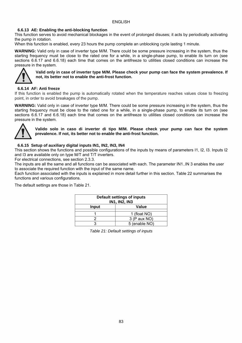
ENGLISH
83
6.6.13 AE: Enabling the anti-blocking function This function serves to avoid mechanical blockages in the event of prolonged disuses; it acts by periodically activating the pump in rotation. When this function is enabled, every 23 hours the pump complete an unblocking cycle lasting 1 minute.
WARNING: Valid only in case of inverter type M/M. There could be some pressure increasing in the system, thus the starting frequency must be close to the rated one for a while, in a single-phase pump, to enable its turn on (see sections 6.6.17 and 6.6.18) each time that comes on the antifreeze to utilities closed conditions can increase the pressure in the system.
Valid only in case of inverter type M/M. Please check your pump can face the system prevalence. If not, its better not to enable the anti-frost function.
6.6.14 AF: Anti freeze If this function is enabled the pump is automatically rotated when the temperature reaches values close to freezing point, in order to avoid breakages of the pump.
WARNING: Valid only in case of inverter type M/M. There could be some pressure increasing in the system, thus the starting frequency must be close to the rated one for a while, in a single-phase pump, to enable its turn on (see sections 6.6.17 and 6.6.18) each time that comes on the antifreeze to utilities closed conditions can increase the pressure in the system.
Valido solo in caso di inverter di tipo M/M. Please check your pump can face the system prevalence. If not, its better not to enable the anti-frost function.
6.6.15 Setup of auxiliary digital inputs IN1, IN2, IN3, IN4 This section shows the functions and possible configurations of the inputs by means of parameters I1, I2, I3. Inputs I2 and I3 are available only on type M/T and T/T inverters. For electrical connections, see section 2.3.3. The inputs are all the same and all functions can be associated with each. The parameter IN1..IN 3 enables the user to associate the required function with the input of the same name. Each function associated with the inputs is explained in more detail further in this section. Table 22 summarises the functions and various configurations.
The default settings are those in Table 21.
Default settings of inputs IN1, IN2, IN3
Input Value
1 1 (float NO) 2 3 (P aux NO) 3 5 (enable NO)
Table 21: Default settings of inputs

ENGLISH
84
Summary of possible configurations of digital
inputs IN1, IN2, IN3 and relative operation
Value Function associated with general input i Display of active function associated
with input
0 Input functions disabled 1 Water failure from external float (NO) F1 2 Water failure from external float (NC) F1 3 Auxiliary setpoint Pi (NO) related to input used F2 4 Auxiliary setpoint Pi (NC) related to input used F2
5 General enable of the inverter from external signal (NO)
F3
6 General enable of the inverter from external signal (NC)
F3
7 General enable of the inverter from external signal (NO) + Reset of resettable blocks
F3
8 General enable of the inverter from external signal (NC) + Reset of resettable blocks
F3
9 Reset of resettable blocks NO
10 Low pressure signal input NO, automatic and manual reset
F4
11 Low pressure signal input NC, automatic and manual reset
F4
12 NO low pressure input, manual reset only F4 13 NC low pressure input, manual reset only F4
Table 22: Input configuration
6.6.15.1 Disabling functions associated with input If an input is configured at 0, each function associated with this input will be disabled, regardless of the signal on the terminals of the input itself.
6.6.15.2 Setting the external float function The external float can be connected to any input, for all electrical connections, refer to paragraph 2.3.3. The float function is obtained by setting the parameter Ix, for the input to which the float signal has been connected, on one of the values in Tabella 23. Activation of the external float function generates a system block. The function is envisaged to connect the input to a signal from a float that indicates a water supply failure. When this function is enabled, the symbol F1 is shown on the STATUS line of the main page. The input must be activated for at least one second for the system to block and indicate the error F1. When in the F1 error condition, the input must be deactivated for at least 30 seconds before the system unblocks. The function behaviour is summarised in Table 23. When several float functions are configured at the same time on different inputs, the system indicates F1 when at least one function is activated and clears the alarm when none are activated.
Response of external float function according to setting of INx and input
Parameter value INx
Input configuration
Input status Operation Display
1
Active with high signal on input
(NO)
Absent Normal None
Present System block due to
lack of water from external float
F1
2
Active with low signal on input
(NO)
Absent System block due to
lack of water from external float
F1
Present Normal None
Table 23: External float function
6.6.15.3 Setting the auxiliary pressure input function Auxiliary pressures P2 and P3 are available only on type M/T and T/T inverters. The signal that enables an auxiliary set point can be supplied on any one of the 4 inputs, (for electrical connections, refer to paragraph 2.3.3).
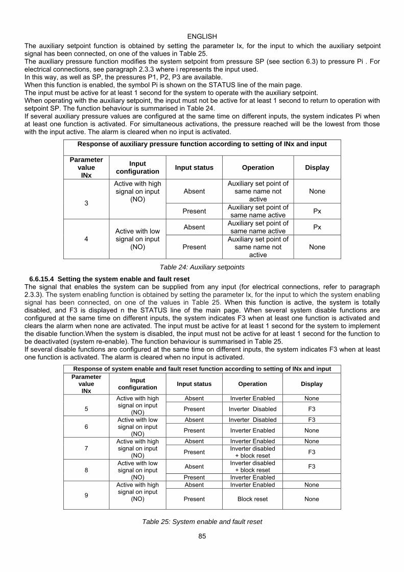
ENGLISH
85
The auxiliary setpoint function is obtained by setting the parameter Ix, for the input to which the auxiliary setpoint signal has been connected, on one of the values in Table 25. The auxiliary pressure function modifies the system setpoint from pressure SP (see section 6.3) to pressure Pi . For electrical connections, see paragraph 2.3.3 where i represents the input used. In this way, as well as SP, the pressures P1, P2, P3 are available. When this function is enabled, the symbol Pi is shown on the STATUS line of the main page. The input must be active for at least 1 second for the system to operate with the auxiliary setpoint. When operating with the auxiliary setpoint, the input must not be active for at least 1 second to return to operation with setpoint SP. The function behaviour is summarised in Table 24. If several auxiliary pressure values are configured at the same time on different inputs, the system indicates Pi when at least one function is activated. For simultaneous activations, the pressure reached will be the lowest from those with the input active. The alarm is cleared when no input is activated.
Response of auxiliary pressure function according to setting of INx and input
Parameter value INx
Input configuration
Input status Operation Display
3
Active with high signal on input
(NO)
Absent Auxiliary set point of
same name not active
None
Present Auxiliary set point of same name active
Px
4 Active with low signal on input
(NO)
Absent Auxiliary set point of same name active
Px
Present Auxiliary set point of
same name not active
None
Table 24: Auxiliary setpoints
6.6.15.4 Setting the system enable and fault reset The signal that enables the system can be supplied from any input (for electrical connections, refer to paragraph 2.3.3). The system enabling function is obtained by setting the parameter Ix, for the input to which the system enabling signal has been connected, on one of the values in Table 25. When this function is active, the system is totally disabled, and F3 is displayed n the STATUS line of the main page. When several system disable functions are configured at the same time on different inputs, the system indicates F3 when at least one function is activated and clears the alarm when none are activated. The input must be active for at least 1 second for the system to implement the disable function.When the system is disabled, the input must not be active for at least 1 second for the function to be deactivated (system re-enable). The function behaviour is summarised in Table 25. If several disable functions are configured at the same time on different inputs, the system indicates F3 when at least one function is activated. The alarm is cleared when no input is activated.
Response of system enable and fault reset function according to setting of INx and input Parameter
value INx
Input configuration
Input status Operation Display
5
Active with high signal on input
(NO)
Absent Inverter Enabled None
Present Inverter Disabled F3
6 Active with low signal on input
(NO)
Absent Inverter Disabled F3
Present Inverter Enabled None
7 Active with high signal on input
(NO)
Absent Inverter Enabled None
Present Inverter disabled
+ block reset F3
8 Active with low signal on input
(NO)
Absent Inverter disabled
+ block reset F3
Present Inverter Enabled
9
Active with high signal on input
(NO)
Absent Inverter Enabled None
Present Block reset None
Table 25: System enable and fault reset

ENGLISH
86
6.6.15.5 Setting low pressure detection (KIWA) The minimum pressure switch that detects low pressure can be connected to any input (for electrical connections, refer to paragraph 2.3.3). The low pressure detecting function is obtained by setting the parameter Ix, for the input to which the enabling signal has been connected, on one of the values in Tabella 26.
Activation of the low pressure detection function generate a system block after time T1 (see T1: Tempo di spegnimento dopo il segnale bassa pressione par. 6.6.2). This function is envisaged to connect the input to a signal from a pressure switch that indicates excessively low pressure on pump intake. When this function is enabled, the symbol F4 is shown on the STATUS line of the main page.
When in the F4 error condition, the input must be deactivated for at least 2 seconds before the system unblocks. The function behaviour is summarised in Table 26. When several low pressure detection functions are configured at the same time on different inputs, the system indicates F4 when at least one function is activated and clears the alarm when none are activated.
Response of system enable and fault reset function according to setting of INx and input
Parameter value INx
Input configuration
Input status Operation Display
10
Active with high signal on input
(NO)
Absent Normal None
Present System block due to low
pressure on intake; automatic + manual reset
F4
11 Active with low signal on input
(NC)
Absent System block due to low
pressure on intake; automatic + manual reset
F4
Present Normal None
12
Active with high signal on input
(NO)
Absent Normal None
Present System block due to low
pressure on intake. Manual reset
F4
13 Active with low signal on input
(NC)
Absent System block due to low
pressure on intake. Manual reset
F4
Present Normal None
Table 26: Low pressure signal detection (KIWA)
6.6.16 Setup of outputs OUT1, OUT2 This section illustrates the functions and possible configurations of the outputs OUT1 and OUT2 via parameters O1 and O2. For electrical connections, see par. 2.3.4. The default settings are those in Table 27.
Default output settings
Output Value
OUT 1 2 (fault NO closes) OUT 2 2 (Pump running NO closes)
Table 27: Default output settings
6.6.16.1 O1: Output 1 function setting Output 1 notifies of an active alarm (i.e. that there is a system block). The output enables use of a normally closed or normally open voltage-free contact. Parameter O1 is associated with the values and functions specified in Table 28.
6.6.16.2 O2: Output 2 function setting Output 2 notifies of electric pump running status (pump on/off). The output enables use of a normally closed or normally open voltage-free contact. Parameter O2 is associated with the values and functions specified in Table 28.

ENGLISH
87
Configuration of functions associated with outputs
Output configuration
OUT1 OUT2 Activation conditions
Output contact status
Activation conditions
Output contact status
0 No function associated
NO contact always open, NC contact always closed
No function associated
NO contact always open, NC contact always closed
1 No function associated
NO contact always closed, NC contact always open
No function associated
NO contact always closed, NC contact always open
2 Presence of blocking errors
In event of blocking errors NO contact closes and NC contact opens
Activation of output in event of blocking errors
When the pump is running, the NO contact closes and the NC contact opens
3 Presence of blocking errors
In event of blocking errors NO contact opens and NC contact closes
Activation of output in event of blocking errors
When the pump is running, the NO contact opens and the NC contact closes
Table 28: Output configuration
6.6.17 SF: Starting frequency Available only for type M/M inverters in sizes 11 and 14 A. SF is the frequency set for the pump’s turn on, in a set time ST (see section 6.6.18. The default value corresponds to the pump's rated frequency, but it can be changed pressing “+” and “-“; it can be changed in a range between Fn and Fn-50%. When FL value is higher than Fn-50%, SF will be limited to the FL minimum frequency. For example when Fn = 50Hz, SF can be set between 50 and 25Hz. When Fn = 50Hz and FL = 30 Hz, SF can be set between 50 and 30Hz.
6.6.18 ST: Starting time Available only for type M/M inverters in sizes 11 and 14 A. ST is the period of time in which SF frequency is supplied (see section 6.6.17), before the frequency is automatically managed by PI parameter. The ST default value is 1 sec. and it its normally the best for most of the pumps. In any case, ST can be changed between 0 and 3 secs. When Ft = 0 secs, frequency will be immediately managed by PI and the pump will turn on at the rated frequency.
6.6.19 RF: Fault and warning log reset To clear the fault and warning log, press and hold the buttons + and – simultaneously for at least 2 seconds. The number of faults present in the log (max. 64) are summarised below the RF symbol. The log can be viewed from the MONITOR menu on the FF page.
6.6.20 PW: Change password The device has a password-enabled protection system. If a password is set, the parameters of the device will be accessible and visible but it will not be possible to change them. The only parameters that allow the password to be changed independently of the setting are: SP, P1, P2, P3, RP, FP, LA, CT.
When a password is used (value of PW different from 0) all modifications are blocked and “XXXX” is displayed on the page PW. If the password is set it allows to navigate through all the pages, but at any attempt to edit a parameter a pop-up appears, asking you to type in the password. When the correct password is typed in the parameters are unlocked and can be edited for 10’ after the last key is pressed. If you want to cancel the password timer, just go to page PW and hold down + and – together for 2”. When the correct password is typed in a padlock is shown opening, while if the wrong password is given a flashing padlock appears. After resetting the factory values the password is set back at “0”. Each change of the password takes effect when Mode or Set is pressed and each subsequent change of a parameter implies typing in the new password again (e.g. the installer makes all the settings with the default PW value = 0 and lastly sets the PW so as to be sure that the machine is already protected without any further action). If the password is lost there are 2 possibilities for editing the parameters of the device:
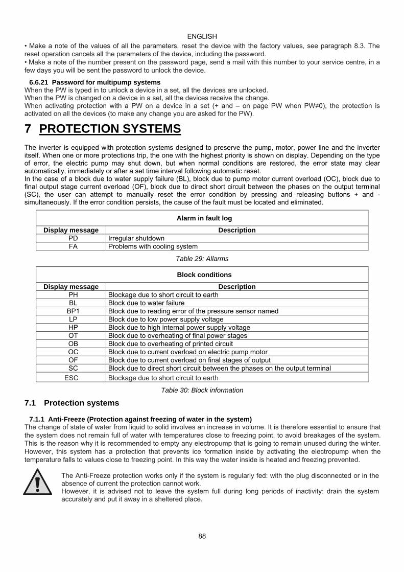
ENGLISH
88
• Make a note of the values of all the parameters, reset the device with the factory values, see paragraph 8.3. The reset operation cancels all the parameters of the device, including the password. • Make a note of the number present on the password page, send a mail with this number to your service centre, in a few days you will be sent the password to unlock the device.
6.6.21 Password for multipump systems When the PW is typed in to unlock a device in a set, all the devices are unlocked. When the PW is changed on a device in a set, all the devices receive the change. When activating protection with a PW on a device in a set (+ and – on page PW when PW≠0), the protection is activated on all the devices (to make any change you are asked for the PW).
7 PROTECTION SYSTEMS
The inverter is equipped with protection systems designed to preserve the pump, motor, power line and the inverter itself. When one or more protections trip, the one with the highest priority is shown on display. Depending on the type of error, the electric pump may shut down, but when normal conditions are restored, the error state may clear automatically, immediately or after a set time interval following automatic reset. In the case of a block due to water supply failure (BL), block due to pump motor current overload (OC), block due to final output stage current overload (OF), block due to direct short circuit between the phases on the output terminal (SC), the user can attempt to manually reset the error condition by pressing and releasing buttons + and - simultaneously. If the error condition persists, the cause of the fault must be located and eliminated.
Alarm in fault log
Display message Description PD Irregular shutdown FA Problems with cooling system
Table 29: Allarms
Block conditions
Display message Description PH Blockage due to short circuit to earth BL Block due to water failure
BP1 Block due to reading error of the pressure sensor named LP Block due to low power supply voltage HP Block due to high internal power supply voltage OT Block due to overheating of final power stages OB Block due to overheating of printed circuit OC Block due to current overload on electric pump motor OF Block due to current overload on final stages of output SC Block due to direct short circuit between the phases on the output terminal
ESC Blockage due to short circuit to earth
Table 30: Block information
7.1 Protection systems
7.1.1 Anti-Freeze (Protection against freezing of water in the system) The change of state of water from liquid to solid involves an increase in volume. It is therefore essential to ensure that the system does not remain full of water with temperatures close to freezing point, to avoid breakages of the system. This is the reason why it is recommended to empty any electropump that is going to remain unused during the winter. However, this system has a protection that prevents ice formation inside by activating the electropump when the temperature falls to values close to freezing point. In this way the water inside is heated and freezing prevented.
The Anti-Freeze protection works only if the system is regularly fed: with the plug disconnected or in the absence of current the protection cannot work. However, it is advised not to leave the system full during long periods of inactivity: drain the system accurately and put it away in a sheltered place.

ENGLISH
89
7.2 Description of blocks 7.2.1 “BL” Block due to water failure
In flow conditions below minimum value, with pressure lower than the set regulation value, a water failure signal is emitted and the system shuts down the pump. The delay interval without pressure and flow can be set in the parameter TB of the TECHNICAL ASSISTANCE menu. If the user inadvertently enters a pressure setpoint higher than the pressure that the electric pump can supply on closure, the system indicates “block due to water failure” (BL) even if this is not precisely the problem. In this case, lower the regulation pressure to a reasonable value, which does not normally exceed 2/3 of the head of the electrical pump installed.
7.2.2 “BP1” Block due to fault on pressure sensor If the inverter detects a fault on the pressure sensor, the pump remains blocked and the error signal “BP1” is displayed. This status starts as soon as the problem is detected and is reset automatically when the correct conditions are restored.
7.2.3 "LP" Block due to low power supply voltage Activated when the line voltage on the power supply terminal falls below the minimum admissible voltage. Reset is only automatic when the voltage on the terminal returns within the specifications.
7.2.4 "HP" Block due to high internal power supply voltage Activated when the internal power supply values are outside the specified range. Reset is only automatic when the voltage returns to within the admissible values. This may be due to voltage surges or excessively brusque shutdown of the pump.
7.2.5 "SC" Block due to direct short circuit between the phases on the output terminal The inverter is equipped with a protection against direct short circuits, which may occur between the phases of the output terminal "PUMP". When this block signal is sent, the user can attempt reset by pressing buttons + and – simultaneously which in any event does not have any effect until 10 seconds has passed since the moment of the short circuit.
7.3 Manual reset of error conditions In error status, the user can reset the fault by overriding a new attempt by pressing and releasing buttons + and -.
7.4 Auto-reset of error conditions In the cases of some malfunctions and block conditions, the system makes a number of attempts at automatic reset of the electric pump. The auto-reset system regards in particular:
- "BL" Block due to water failure - "LP" Block due to low power supply voltage - "HP" Block due to internal high voltage - "OT" Block due to overheating of final power stages - "OB" Block due to overheating of printed circuit - "OC" Block due to current overload on electric pump motor - "OF" Block due to current overload on final stages of output - "BP" Block due to fault on pressure sensor
If, for example, the pump is blocked due to water supply failure, the inverter automatically starts a test procedure to verify that the unit is effectively without water permanently. During the sequence of operations, if a reset attempt succeeds (for example water has returned), the procedure is interrupted and normal operation is resumed. Table 31 shows the sequence of operations performed by the inverter for the different types of block.

ENGLISH
90
Automatic reset of error conditions
Display message Description Automatic reset sequence
BL Block due to water failure - One attempt every 10 minutes for a total of 6 attempts - One attempt every hour for a total of 24 attempts - One attempt every 24 hours for a total of 30 attempts
LP Block due to low line voltage - Reset when specified voltage is restored
HP Block due to high internal power supply voltage
- Reset when voltage returns to a specified value
OT Block due to overheating of final power stages (TE > 100°C)
- Reset when temperature of final power stages falls below 85°C
OB Block due to overheating of printed circuit (BT> 120°C)
- Reset when temperature of printed circuit falls below 100°C
OC Block due to current overload on electric pump motor
‐ An attempt every 10 minutes for a total of 6 attempts - An attempt every hour for a total of 24 attempts - An attempt every 24 hours for a total of 30 attempts
OF Block due to current overload on final stages of output
- An attempt every 10 minutes for a total of 6 attempts - An attempt every hour for a total of 24 attempts - An attempt every 24 hours for a total of 30 attempts
Table 31: Auto-reset of blocks
8 RESET AND FACTORY SETTINGS
8.1 General system reset To reset the system, hold down the 4 keys simultaneously for 2 sec. This operation is the same as disconnecting the power, waiting for it to close down completely and supplying power again. The reset does not delete the settings saved by the user.
8.2 Factory settings The device leaves the factory with a series of preset parameters which may be changed according to the user’s requirements. Each change of the settings is automatically saved in the memory and, if desired, it is always possible to restore the factory conditions (see Restoring the factory settings par 8.3 – Restoring the factory settings).
8.3 Restoring the factory settings To restore the factory values, switch off the device, wait until the display has switched off completely, press and hold down the “SET” and “+” keys and turn on the power; release the two keys only when the letters “EE” appear. This restores the factory settings (a message and a rereading on EEPROM of the factory settings permanently saved in the FLASH memory). Once all the parameters have been set, the device returns to normal operation. NOTE: Once the factory values have been restored it will be necessary to reset all the parameters that characterise the system (gains, setpoint pressure, etc.) as at the first installation.
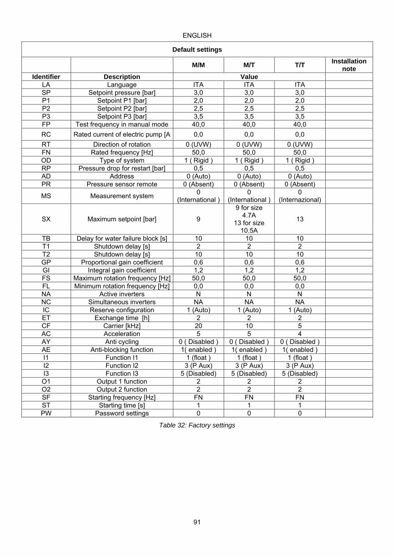
ENGLISH
91
Table 32: Factory settings
Default settings
M/M M/T T/T Installation
note Identifier Description Value
LA Language ITA ITA ITA SP Setpoint pressure [bar] 3,0 3,0 3,0 P1 Setpoint P1 [bar] 2,0 2,0 2,0 P2 Setpoint P2 [bar] 2,5 2,5 2,5 P3 Setpoint P3 [bar] 3,5 3,5 3,5 FP Test frequency in manual mode 40,0 40,0 40,0
RC Rated current of electric pump [A 0,0 0,0 0,0
RT Direction of rotation 0 (UVW) 0 (UVW) 0 (UVW) FN Rated frequency [Hz] 50,0 50,0 50,0 OD Type of system 1 ( Rigid ) 1 ( Rigid ) 1 ( Rigid ) RP Pressure drop for restart [bar] 0,5 0,5 0,5 AD Address 0 (Auto) 0 (Auto) 0 (Auto) PR Pressure sensor remote 0 (Absent) 0 (Absent) 0 (Absent)
MS Measurement system 0
(International ) 0
(International ) 0
(Internazional)
SX Maximum setpoint [bar] 9
9 for size 4.7A
13 for size 10.5A
13
TB Delay for water failure block [s] 10 10 10 T1 Shutdown delay [s] 2 2 2 T2 Shutdown delay [s] 10 10 10 GP Proportional gain coefficient 0,6 0,6 0,6 GI Integral gain coefficient 1,2 1,2 1,2 FS Maximum rotation frequency [Hz] 50,0 50,0 50,0 FL Minimum rotation frequency [Hz] 0,0 0,0 0,0 NA Active inverters N N N NC Simultaneous inverters NA NA NA IC Reserve configuration 1 (Auto) 1 (Auto) 1 (Auto) ET Exchange time [h] 2 2 2 CF Carrier [kHz] 20 10 5 AC Acceleration 5 5 4 AY Anti cycling 0 ( Disabled ) 0 ( Disabled ) 0 ( Disabled ) AE Anti-blocking function 1( enabled ) 1( enabled ) 1( enabled ) I1 Function I1 1 (float ) 1 (float ) 1 (float ) I2 Function I2 3 (P Aux) 3 (P Aux) 3 (P Aux) I3 Function I3 5 (Disabled) 5 (Disabled) 5 (Disabled) O1 Output 1 function 2 2 2 O2 Output 2 function 2 2 2 SF Starting frequency [Hz] FN FN FN ST Starting time [s] 1 1 1 PW Password settings 0 0 0

ENGLISH
92
9 FIRMWARE UPDATE
9.1 General This chapter describes how you can update one or more inverters if you have an inverter with a more recent firmware. As already illustrated in the manual par. 4.2, for use in multi-inverter configuration, it is necessary for all the components that are to be put into communication to have the same firmware versions. If they are different, they must be updated to align the older versions. Definitions used below: Master: device from which a firmware is taken to load it in another inverter. Slave: inverter in the state of receiving a firmware update.
9.2 Update When several inverters are connected together, a control procedure is started which compares the firmware versions. If they are different, the inverters each show a pop-up that communicates the state of non-alignment of the firmware and the version of their own installed firmware. The pop-up allows you to proceed with the update by pressing “+” on any one of the inverters. The firmware update is carried out simultaneously on all the connected inverters that require it. During the update the Slave inverter shows the message “LV LOADER v1.x” and a bar indicating the progress of the update. During the firmware update the Slave and Master inverters involved cannot carry out pumping functions. The update takes about 1 minute. At the end of this phase, the inverters will restart. Once they have been restarted, they can be connected and form the multi-inverter group. If problems have occurred and the firmware has not been correctly installed, the Slave inverter might remain in an inconsistent status. In this situation the message “CRC Error” appears on this inverter. To correct the error it is sufficient to disconnect the power supply to the Slave inverter, wait for it to be completely switched off, and then supply the power again. Switching on the Slave inverter automatically generates a new update process.