Active Damping Method for Mitigation of Resonance Propagation in Grid ... · Propagation in...
18
International Journal of Electrical and Computer Engineering. ISSN 0974-2190 Volume 8, Number 1 (2016), pp. 19-36 © International Research Publication House http://www.irphouse.com Active Damping Method for Mitigation of Resonance Propagation in Grid-connected and Islanding Microgrid by using FLC P. Venkata Sarath 1 Assistant Professor, Dept. EEE A.I.T.S-Rajampet, A.P, INDIA. K. Sreedhar 2 Assistant Professor, Dept. EEE A.I.T.S-Rajampet, A.P, INDIA. M. Amaranatha Reddy 3 PG Student, Dept. EEE A.I.T.S-Rajampet, A.P, INDIA. Abstract The shunt capacitor banks and underground links application can present force circulation framework resonances. At that point the effects of current controlled and voltage controlled circulated era (DG) units to microgrid reverberation spread is researched. A straight voltage controlled DG unit with a LC channel has a short out component at the chose symphonious frequencies. While a current controlled DG unit exhibits an open circuit qualities. Because of various practices at consonant frequencies, particular symphonious moderation systems are created for voltage controlled and current controlled DG units individually. A voltage controlled DG unit-based dynamic symphonious damping strategy for both framework associated framework and islanding microgrid framework is talked about in this paper. An enhanced virtual impedance control technique with a virtual damping resistor and a nonlinear virtual capacitor is prescribed. The adequacy of the proposed damping procedure is investigated by utilizing both a solitary DG unit and twofold or various parallel DG units. Here fuzzy logic is used for controlling the simpered systems tool has proved that the combined system will at the same time inject maximum power and provide dynamic frequency support to the grid. Keywords: Active power filter, microgrid, distributed power generation (DPG), resonance propagation, virtual impedance, droop control, power quality.
Transcript of Active Damping Method for Mitigation of Resonance Propagation in Grid ... · Propagation in...
International Journal of Electrical and Computer Engineering.
ISSN 0974-2190 Volume 8, Number 1 (2016), pp. 19-36
© International Research Publication House
http://www.irphouse.com
Active Damping Method for Mitigation of Resonance
Propagation in Grid-connected and Islanding
Microgrid by using FLC
P. Venkata Sarath1
Assistant Professor, Dept. EEE
A.I.T.S-Rajampet, A.P, INDIA.
K. Sreedhar2
Assistant Professor, Dept. EEE
A.I.T.S-Rajampet, A.P, INDIA.
M. Amaranatha Reddy3
PG Student, Dept. EEE
A.I.T.S-Rajampet, A.P, INDIA.
Abstract
The shunt capacitor banks and underground links application can present force
circulation framework resonances. At that point the effects of current controlled
and voltage controlled circulated era (DG) units to microgrid reverberation
spread is researched. A straight voltage controlled DG unit with a LC channel
has a short out component at the chose symphonious frequencies. While a
current controlled DG unit exhibits an open circuit qualities. Because of various
practices at consonant frequencies, particular symphonious moderation systems
are created for voltage controlled and current controlled DG units individually.
A voltage controlled DG unit-based dynamic symphonious damping strategy
for both framework associated framework and islanding microgrid framework
is talked about in this paper. An enhanced virtual impedance control technique
with a virtual damping resistor and a nonlinear virtual capacitor is prescribed.
The adequacy of the proposed damping procedure is investigated by utilizing
both a solitary DG unit and twofold or various parallel DG units. Here fuzzy
logic is used for controlling the simpered systems tool has proved that the
combined system will at the same time inject maximum power and provide
dynamic frequency support to the grid.
Keywords: Active power filter, microgrid, distributed power generation
(DPG), resonance propagation, virtual impedance, droop control, power quality.

20 P. Venkata Sarath, K. Sreedhar and M. Amaranatha Reddy
I. INTRODUCTION
The snow balling use of nonlinear burdens can prompted noteworthy symphonious
contamination in a force dispersion framework. The consonant contortion may energize
troublesome resonances, for the most part in force frameworks with underground links
and shunt capacitor banks. So as to diminish framework resonances, uninvolved
channels or damping resistors can be put in appropriation systems. The alleviation of
reverberation proliferation utilizing latent segments utilizing this parts are a couple
surely knew issues, for example, extra speculation and force misfortune, on the grounds
that an aloof channel may notwithstanding bring extra resonances on the off chance that
it is the framework composed or introduced without knowing itemized about
framework designs.
To get away from the appropriation of uninvolved damping gear, diverse sorts of
dynamic damping techniques have been created, among them the resistive dynamic
force channel (R-APF) is oftentimes considered as a promising approach to understand
the well execution. Customarily, the rule of R-APF is to copy the practices of aloof
damping resistors by applying a shut circle current-controlled technique (CCM) to
control electronic (PE) converters.
This control class the R-APF can be simply displayed as a virtual symphonious resistor
in the event that it is seen at the dispersion framework levels. The discrete tuning
strategy was proposed to Conform damping resistances at different consonant requests.
The R-APF basically functions as a nonlinear resistor, The procedure of different R-
APFs was likewise considered, where an intriguing hanging control was intended to
proposition self-ruling symphonious force sharing capacity among parallel R-APFs.
For current controlled DG units, the helper R-APF capacity can be flawlessly
consolidated into the essential DG genuine force infusion capacity by altering the
present reference. The ordinary CCM can barely give direct voltage support amid
microgrid islanding operation, and conquer this constraint, to improve the voltage-
controlled technique (VCM) was as of late made arrangements for DG units with high-
arrange LCL or LC channels. It can be seen that the control strategy in directs the DG
unit as virtual impedance. Which is relies on upon the current feeder impedance, when
the feeder impedance is inductive. This technique couldn't give enough damping
impacts to framework reverberation.
To accomplish better operation of matrix associated and islanding small scale networks,
this paper considers a basic consonant engendering model in which the microgrid is set
at the less than desirable end of the feeder. To decrease the feeder consonant
mutilations, an adjusted virtual impedance-based dynamic damping strategy that
comprises of a virtual nonlinear capacitor and a virtual resistor is likewise proposed.
The virtual capacitor expels the effects of LCL channel framework side inductor and
the virtual resistor is interfaced to the less than desirable end of the feeder and to give
dynamic damping administration.
II. MODELING OF DG UNITS IN MICROGRID SYSTEM
The figure1 delineates the arrangement of a solitary stage microgrid framework, where
a couple DG units are interconnected to the point of normal coupling (PCC) through a
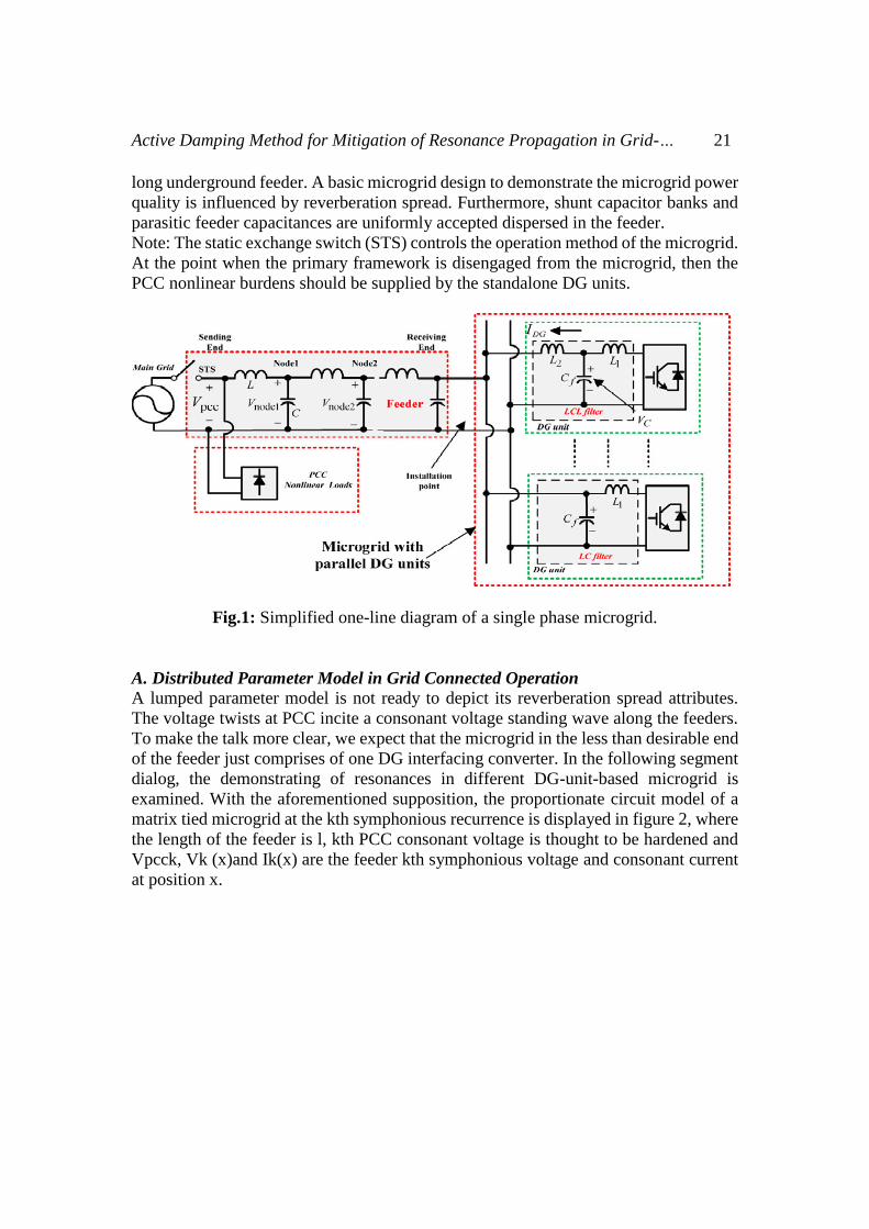
Active Damping Method for Mitigation of Resonance Propagation in Grid-… 21
long underground feeder. A basic microgrid design to demonstrate the microgrid power
quality is influenced by reverberation spread. Furthermore, shunt capacitor banks and
parasitic feeder capacitances are uniformly accepted dispersed in the feeder.
Note: The static exchange switch (STS) controls the operation method of the microgrid.
At the point when the primary framework is disengaged from the microgrid, then the
PCC nonlinear burdens should be supplied by the standalone DG units.
Fig.1: Simplified one-line diagram of a single phase microgrid.
A. Distributed Parameter Model in Grid Connected Operation
A lumped parameter model is not ready to depict its reverberation spread attributes.
The voltage twists at PCC incite a consonant voltage standing wave along the feeders.
To make the talk more clear, we expect that the microgrid in the less than desirable end
of the feeder just comprises of one DG interfacing converter. In the following segment
dialog, the demonstrating of resonances in different DG-unit-based microgrid is
examined. With the aforementioned supposition, the proportionate circuit model of a
matrix tied microgrid at the kth symphonious recurrence is displayed in figure 2, where
the length of the feeder is l, kth PCC consonant voltage is thought to be hardened and
Vpcck, Vk (x)and Ik(x) are the feeder kth symphonious voltage and consonant current
at position x.

22 P. Venkata Sarath, K. Sreedhar and M. Amaranatha Reddy
Fig.2: Equivalent circuit of a single grid-connected DG unit (kth harmonic frequency).
Obtaining the harmonic voltage current standing wave equations at the harmonic order
k is as follows
Vk(x) = 𝐴𝑒−𝛾𝑥 + 𝐵𝑒𝛾𝑥 (1)
Ik(x) = 1
𝑧( 𝐴𝑒−𝛾𝑥 - 𝐵𝑒𝛾𝑥) (2)
Where A and B are constants and are determined by feeder boundary conditions.
z and γ are the characteristics impedance of the feeder without considering the line
resistance as
z=√𝐿
𝐶 (3)
𝛾 = 𝑗𝑘𝑤𝑓√𝐿𝐶 (4)
Where wf is the fundamental frequency, L is the feeder equivalent inductance/km, C is
the feeder equivalent shunt capacitance/km.
(1) DG Units with CCM and R-APF Control
Determine the boundary conditions of the feeder, the equivalent harmonic impedance
(ZADk) of the DG unit need be derived. The current reference (Iref ) of a CCM-based
DG unit can be obtained as
Ireff = Ireff - IAD =Ireff - 𝐻𝐷(𝑆).𝑉(𝑙)
𝑅𝑣 (5)
Active Damping Method for Mitigation of Resonance Propagation in Grid-… 23
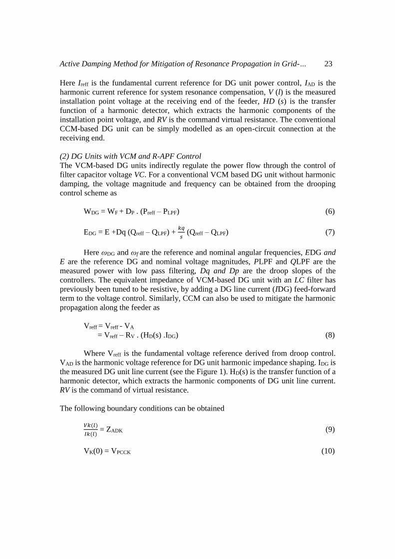
Here Ireff is the fundamental current reference for DG unit power control, IAD is the
harmonic current reference for system resonance compensation, V (l) is the measured
installation point voltage at the receiving end of the feeder, HD (s) is the transfer
function of a harmonic detector, which extracts the harmonic components of the
installation point voltage, and RV is the command virtual resistance. The conventional
CCM-based DG unit can be simply modelled as an open-circuit connection at the
receiving end.
(2) DG Units with VCM and R-APF Control
The VCM-based DG units indirectly regulate the power flow through the control of
filter capacitor voltage VC. For a conventional VCM based DG unit without harmonic
damping, the voltage magnitude and frequency can be obtained from the drooping
control scheme as
WDG = WF + DP . (Preff – PLPF) (6)
EDG = E +Dq (Qreff – QLPF) + 𝑘𝑞
𝑠 (Qreff – QLPF) (7)
Here ωDG and ωf are the reference and nominal angular frequencies, EDG and
E are the reference DG and nominal voltage magnitudes, PLPF and QLPF are the
measured power with low pass filtering, Dq and Dp are the droop slopes of the
controllers. The equivalent impedance of VCM-based DG unit with an LC filter has
previously been tuned to be resistive, by adding a DG line current (IDG) feed-forward
term to the voltage control. Similarly, CCM can also be used to mitigate the harmonic
propagation along the feeder as
Vreff = Vreff - VA
= Vreff – RV . (HD(s) .IDG) (8)
Where Vreff is the fundamental voltage reference derived from droop control.
VAD is the harmonic voltage reference for DG unit harmonic impedance shaping. IDG is
the measured DG unit line current (see the Figure 1). HD(s) is the transfer function of a
harmonic detector, which extracts the harmonic components of DG unit line current.
RV is the command of virtual resistance.
The following boundary conditions can be obtained
𝑉𝑘(𝑙)
𝐼𝑘(𝑙) = ZADK (9)
VK(0) = VPCCK (10)

24 P. Venkata Sarath, K. Sreedhar and M. Amaranatha Reddy
Solving the equations 1, 2, 9 and 10 we get the harmonic propagation at the harmonic
order k can be express as
V(x)k =𝑍𝑎𝑑𝑘 cosh(γ( 1−𝑥))+ sinh(γ( 1−𝑥))
𝑍𝑎𝑑𝑘 cosh( 𝛾𝑙)+ 𝑍 sinh(𝛾𝑙)𝑉PCCK (11)
B. Distributed Parameter Model in Islanding Operation
The VCM operation of DG units is needed for direct voltage support. When only a
single DG unit is located in the islanding system, constant voltage magnitude and
constant frequency (CVMCF) control can be used. Considering the focus on this section
is to investigate the harmonic voltage damping in a stand-alone islanding system. A
single DG unit at the receiving end of the feeder is considered. The circuit model of an islanding system at the kth harmonic order is illustrated in Figure
3, where VCM-based DG unit is also modelled as an equivalent harmonic impedance
using the control scheme. The nonlinear PCC load in this case is modelled as a harmonic
current source at the sending end of the feeder.
Fig. 3: Equivalent circuit of a single islanding unit (kth harmonic frequency).
The knowledge of boundary conditions at both sending end and receiving end as
Ik(0) = ILoadk (12)
𝑉𝑘(𝑙)
𝐼𝑘(𝑙) = ZADK (13)
kth harmonic voltage distortion along the feeder can be obtained as
Vk(x)=( 𝑒−𝛾𝑥
1+(𝑧−𝑍𝑎𝑑𝑘
𝑧+𝑧𝑎𝑑𝑘)𝑒−2𝛾𝑙
−𝑒𝛾𝑥
1+(𝑧+𝑧𝑎𝑑𝑘)/(𝑧−𝑧𝑎𝑑𝑘)𝑒2𝛾𝑙)ZLoadk (14)

Active Damping Method for Mitigation of Resonance Propagation in Grid-… 25
Equation (14) can be noticed that the voltage propagation in islanding system harmonic
is also related to the DG-unit equivalent harmonic impedance.
III. ESTIMATION OF DAMPING PERFORMANCE
The performance of VCM-based DG units at different operation modes is investigated
in this section.
A) Evaluation of a Single DG Unit at the End of the Feeder:
Fig.4: Harmonic voltage amplification in a single DG unit grid-connected operation
(I)Grid-Connected mode of Operation:
The performance of a grid tied DG unit with an LCL filter is investigated. Figure 4 is
harmonic voltage distortions along a 6 km feeder. The harmonic voltage distortion
factor here is normalized to the voltage distortions at PCC as V (x)k/VPCCk , When the
conventional VCM without damping is applied to the DG units, the LCL filter capacitor
voltage is ripple free and the DG unit works as an inductor (L2) at the harmonic
frequencies, It can be seen that the feeder is sensitive to 7th harmonic voltage distortion
26 P. Venkata Sarath, K. Sreedhar and M. Amaranatha Reddy
at the PCC. The maximum obvious 7th harmonic voltage propagation is effectively
reduced as shown Figure 4(c).
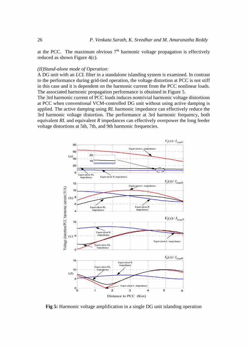
(II)Stand-alone mode of Operation:
A DG unit with an LCL filter in a standalone islanding system is examined. In contrast
to the performance during grid-tied operation, the voltage distortion at PCC is not stiff
in this case and it is dependent on the harmonic current from the PCC nonlinear loads.
The associated harmonic propagation performance is obtained in Figure 5.
The 3rd harmonic current of PCC loads induces nontrivial harmonic voltage distortions
at PCC when conventional VCM-controlled DG unit without using active damping is
applied. The active damping using RL harmonic impedance can effectively reduce the
3rd harmonic voltage distortion. The performance at 3rd harmonic frequency, both
equivalent RL and equivalent R impedances can effectively overpower the long feeder
voltage distortions at 5th, 7th, and 9th harmonic frequencies.
Fig 5: Harmonic voltage amplification in a single DG unit islanding operation

Active Damping Method for Mitigation of Resonance Propagation in Grid-… 27
B. Evaluation of Multiple DG Units at the End of the Feeder
The performance of a microgrid with multiple DG units is increasingly discussed in the
recent literature. In addition to achieve proper power sharing among multiple DG units,
realizing superior harmonic damping performance in a collaborative manner is also
attractive. For parallel DG units as shown in Fig. 1, they shall share the active damping
current according to their respective power rating. However, phase angle difference
between damping resistor and RL damping impedance may bring some harmonic
circulating currents. To simplify the discussion, two VCM controlled DG units at the
same power rating are used to equally share the harmonic current associated with the
active damping control.
If the DG unit with an LC filter is controlled as a harmonic damping resistor R while
the other one with an LCL filter is regulated as the RL damping impedance, the
corresponding circuit diagram at the harmonic order k can be illustrated in Fig. 6. As
shown, the harmonic impedances of these two DG units have the same resistive part.
However, for the DG unit with an LCL filter, its equivalent impedance also has an
inductive part jkωf L2.
Fig. 6. Circuit diagram of a double-DG-based microgrid at the kth harmonic
frequency.
IV. FUZZY LOGIC CONTROL
The Fuzzy logic control consists of set of linguistic variables. Here the PI controller is
replaced with Fuzzy Logic Control. The mathematical modelling is not required in
FLC. FLC consists of
1. Fuzzification
Membership function values are assigned to linguistic variables. In this scaling factor
is between 1 and -1.
2. Inference Method
There are several composition methods such as Max-Min and Max-Dot have been
proposed and Min method is used.
3. Defuzzificaion
A plant requires non fuzzy values to control, so Defuzzificaion is used. The output of
FLC controls the switch in the inverter. To control these parameters they are sensed and

28 P. Venkata Sarath, K. Sreedhar and M. Amaranatha Reddy
compared with the reference values. To obtain this the membership functions of fuzzy
controller are shown in fig (7).
The set of FC rules are derived from
u=-[α E + (1-α)*C] (15)
Where α is self-adjustable factor which can regulate the whole operation. E is the error
of the system, C is the change in error and u is the control variable.
Fig. 7: Fuzzy logic Controller
A large value of error E indicates that given system is not in the balanced state. If the
system is unbalanced, the controller should enlarge its control variables to balance the
system as early as possible.
Fig.8: Simulation System Schematic Diagram.
V. SIMULATION RESULTS
Simulated results have been obtained from a single-phase low voltage microgrid by
using Fuzzy Logic controller. To emulate the behaviour of six kilometres feeder with
distributed parameters, a DG unit with an LCL filter is connected to PCC through a

Active Damping Method for Mitigation of Resonance Propagation in Grid-… 29
ladder network with six identical LC filter units. Each LC filter represents 1 km feeder.
To provide some passive damping effects to the feeder, the LC filter inductor stray
resistance is set to 0.12 Ω.
A. Single DG Unit Grid Tied Operation
At first, the performance of a grid connected DG unit with an LCL filter is examined.
The PCC voltage in this simulation is stiff and it has 2.0% distortion at each lower order
harmonic frequency (3rd, 5th, 7th, and 9th harmonics).
Fig.9. Mitigation of distribution feeder harmonic propagation using virtual resistor and
virtual negative inductor.
Consequently, the total harmonic distortion (THD) of PCC voltage is 4.0%. When the
conventional VCM method without damping is applied to the DG unit, the harmonic
voltages at PCC, nodes 1, 3, 5, and DG unit filter capacitor are presented in Fig. 10.
The node numbers here represent the distance (in kilometres) from the voltage
measurement point to PCC.

30 P. Venkata Sarath, K. Sreedhar and M. Amaranatha Reddy
Fig.10. Harmonic voltage amplification during a single DG unit grid connected
operation (without damping) [from upper to lower: (a) PCC voltage (THD = 4.0%); (b)
node 1 voltage (THD = 4.56%); (c) node 3 voltage (THD = 10.91%); (d) node 5 voltage
(THD = 12.59%); (e) DG unit filter capacitor voltage (THD = 0.38%)].
It can be seen the 7th harmonic voltage is more obviously amplified at the nodes 3 and
5. This is consistent with the analysis in Fig. 4(c), where the feeder is sensitive to the
7th harmonic voltage at PCC. At the same time, the DG unit LCL filter capacitor voltage
is almost ripple free as shown in channel (e), as no damping control scheme is applied
to the DG unit. When the proposed control method with a virtual nonlinear capacitor
and a virtual damping resistor is applied to the DG unit, the harmonic voltage drops on
the LCL filter grid-side inductor (L2) are compensated and the DG unit behaves as a
damping resistor at the end of the feeder. However, compared to the situation without
any damping in Fig. 10(e), the capacitor voltage of the DG unit as shown in Fig. 11(e)
is distorted due to the regulation of virtual harmonic impedance.
B. Single DG Unit Islanding Operation
In addition to grid-connected operation, the performance of a single DG unit in
islanding operation is also investigated. In this case, the PCC load is a single-phase
diode rectifier and it is supplied by the DG unit through long feeder. When the

Active Damping Method for Mitigation of Resonance Propagation in Grid-… 31
conventional VCM without damping is adopted, the performance of the system is
obtained in Fig. 12.
Similar to the grid tied operation, the voltage waveforms at PCC, nodes 1, 3, and 5, and
DG unit filter capacitor are shown from channels (a) to (e), respectively. It can be easily
seen that the third voltage distortions are more obviously amplified. This performance
is also consistent with the theoretical analysis in Fig. 5. It demonstrates that the third
harmonic distortion observed in Fig. 12 is effectively suppressed.
Fig.11. Harmonic voltage amplification during a single DG unit grid connected
operation (with virtual nonlinear capacitor and resistor based active damping) [from
upper to lower: (a) PCC voltage (THD = 4.0%); (b) node 1 voltage (THD = 4.1%); (c)
node 3 voltage (THD = 3.7%); (d) node 5 voltage (THD = 3.2%); and (e) DG unit filter
capacitor voltage (THD = 5.4%)].

32 P. Venkata Sarath, K. Sreedhar and M. Amaranatha Reddy
Fig.12. Harmonic voltage amplification during a single DG unit islanding operation
(without damping) [from upper to lower: (a) PCC voltage (THD = 15.2%); (b) node 1
voltage (THD = 14.7%); (c) node 3 voltage (THD = 11.9%); (d) node 5 voltage (THD
= 10.5%); and (e) DG unit filter capacitor voltage (THD = 1.6%)].
C. Multiple DG Units Grid-Tied Operation
To verify the circulating harmonic current between multiple DG units, two grid
connected DG units at the same power rating are placed at the receiving end of the
feeder. In this simulation, DG unit 1 is interfaced to the feeder receiving end with an
LC filter while DG unit 2 has an LCL filter. The PCC voltage harmonics are selected to
be the same as that in Fig. 10. When both DG units are operating without any virtual
impedance control, DG unit 1 essentially behaves as short circuit at the harmonics and
DG unit 2 works as an equivalent inductor L2,
Active Damping Method for Mitigation of Resonance Propagation in Grid-… 33
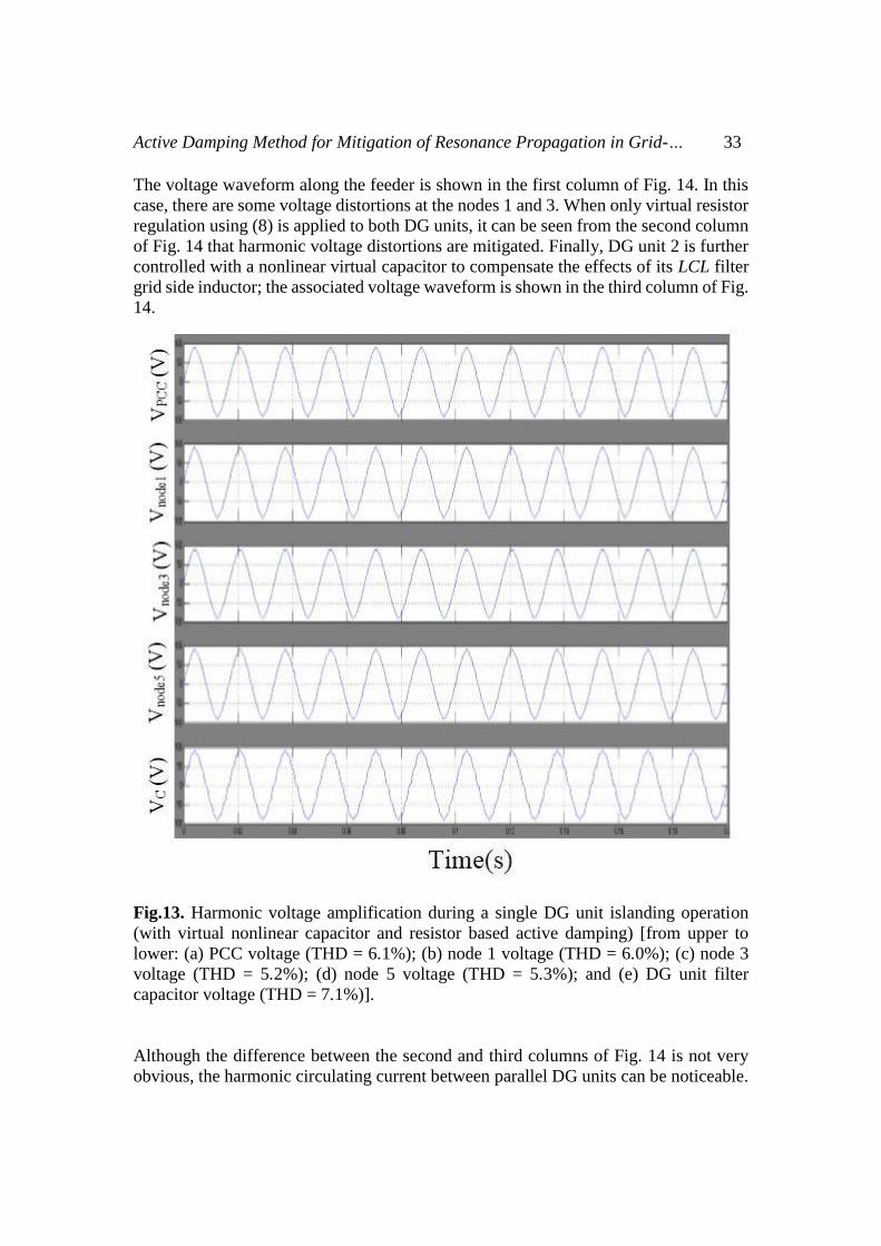
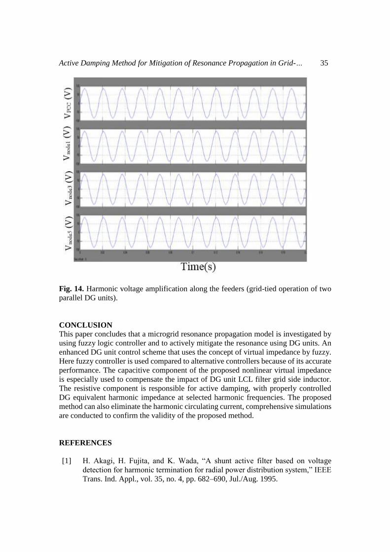
The voltage waveform along the feeder is shown in the first column of Fig. 14. In this
case, there are some voltage distortions at the nodes 1 and 3. When only virtual resistor
regulation using (8) is applied to both DG units, it can be seen from the second column
of Fig. 14 that harmonic voltage distortions are mitigated. Finally, DG unit 2 is further
controlled with a nonlinear virtual capacitor to compensate the effects of its LCL filter
grid side inductor; the associated voltage waveform is shown in the third column of Fig.
14.
Fig.13. Harmonic voltage amplification during a single DG unit islanding operation
(with virtual nonlinear capacitor and resistor based active damping) [from upper to
lower: (a) PCC voltage (THD = 6.1%); (b) node 1 voltage (THD = 6.0%); (c) node 3
voltage (THD = 5.2%); (d) node 5 voltage (THD = 5.3%); and (e) DG unit filter
capacitor voltage (THD = 7.1%)].
Although the difference between the second and third columns of Fig. 14 is not very
obvious, the harmonic circulating current between parallel DG units can be noticeable.
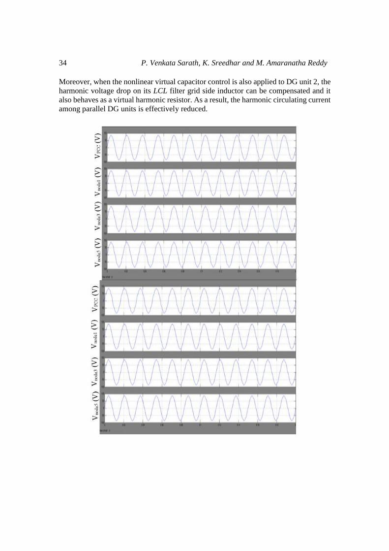
34 P. Venkata Sarath, K. Sreedhar and M. Amaranatha Reddy
Moreover, when the nonlinear virtual capacitor control is also applied to DG unit 2, the
harmonic voltage drop on its LCL filter grid side inductor can be compensated and it
also behaves as a virtual harmonic resistor. As a result, the harmonic circulating current
among parallel DG units is effectively reduced.
Active Damping Method for Mitigation of Resonance Propagation in Grid-… 35
Fig. 14. Harmonic voltage amplification along the feeders (grid-tied operation of two
parallel DG units).
CONCLUSION
This paper concludes that a microgrid resonance propagation model is investigated by
using fuzzy logic controller and to actively mitigate the resonance using DG units. An
enhanced DG unit control scheme that uses the concept of virtual impedance by fuzzy.
Here fuzzy controller is used compared to alternative controllers because of its accurate
performance. The capacitive component of the proposed nonlinear virtual impedance
is especially used to compensate the impact of DG unit LCL filter grid side inductor.
The resistive component is responsible for active damping, with properly controlled
DG equivalent harmonic impedance at selected harmonic frequencies. The proposed
method can also eliminate the harmonic circulating current, comprehensive simulations
are conducted to confirm the validity of the proposed method.
REFERENCES
[1] H. Akagi, H. Fujita, and K. Wada, “A shunt active filter based on voltage
detection for harmonic termination for radial power distribution system,” IEEE
Trans. Ind. Appl., vol. 35, no. 4, pp. 682–690, Jul./Aug. 1995.

36 P. Venkata Sarath, K. Sreedhar and M. Amaranatha Reddy
[2] K. Wada, H. Fujita, and H. Akagi, “Consideration of a shunt active filter based
on voltage detection for installation on a long distribution feeder,” IEEE Trans.
Ind. Appl., vol. 38, no. 4, pp. 1123–1130, Jul./Aug. 2002.
[3] P.-T. Cheng and T.-L. Lee, “Distributed active filter systems (DAFSs): A new
approach to power system harmonics,” IEEE Trans. Ind. Appl., vol. 42, no. 5,
pp. 1301–1309, Sep./Oct. 2006.
[4] T.-L. Lee and P.-T. Cheng, “Design of a new cooperative harmonic filtering
strategy for distributed generation interface converters in an islanding network,”
IEEE Trans. Power Electron., vol. 42, no. 5, pp. 1301–1309, Sep. 2007.
[5] T.-L. Lee, J.-C. Li, and P.-T. Cheng, “Discrete frequency-tuning active filter for
power system harmonics,” IEEE Trans. Power Electron., vol. 24, no. 5, pp.
1209–1217, Apr. 2009.
[6] N. Pogaku and T. C. Green, “Harmonic mitigation throughout a distribution
system: “A distributed-generator-based solution,” IEE Proc.Gener. Transmiss.
Distrib., vol. 153, no. 3, pp. 350–358, May 2006.
[7] Y.W. Li, D. M. Vilathgamuwa, and P. C. Loh, “Design, analysis and real time
testing of a controller for multi-bus microgrid system,” IEEE Trans. Power
Electron., vol. 19, no. 5, pp. 1195–1204, Sep. 2004.
[8] J. He and Y. W. Li, “Analysis, design and implementation of virtual impedance
for power electronics interfaced distributed 47, no. 6, pp. 2525–2538,
Nov./Dec. 2011.
[9] J. He, Y. W. Li, and S. Munir, “A flexible harmonic control approach through
voltage controlled DG-grid interfacing converters,” IEEE Trans. Ind. Electron.,
vol. 59, no. 1, pp. 444–455, Jan. 2012.
[10] C. J. Chou, Y. K. Wu, G. Y. Han, and C. Y. Lee, “Comparative evaluation of
the HVDC and HVAC links integrated in a large offshore wind farm: An actual
case study in Taiwan,” IEEE Trans. Ind. Appl., vol. 48, no. 5, pp. 1639–1648,
Sep./Oct. 2008.
Author’s Profile:
M.AMARANATHA REDDY: He was born in 1993. He obtained his Bachelor degree
in Electrical and Electronics Engineering in 2014 from NIST, Rajampet. Currently
Pursuing his Post Graduation in Electrical Power Engineering in AITS, Rajampet,
Kadapa (dist.).