Active balancing control for time-delay rotor via linear ...
13
Active balancing control for time-delay rotor via linear-quadratic regulator Juan Xu , a,b Yang Zhao, c Zhanfeng Xu, c and Benhong Zhang a, * a Hefei University of Technology, School of Computer Science and Information Engineering, Hefei, China b Anhui Fuhuang Technology Co., Ltd., Hefei, China c Hefei University of Technology, School of Mechanical Engineering, Hefei, China Abstract. Many imaging platforms, e.g., robotic devices and autonomous systems, require timely reaction to external events. The active balancing control is important to suppress rotor vibration and hence acquire stable videos and imagery. However, there is an inevitable delay in active balancing control of the high-speed, time-delay rotor systems. Eliminating this delay is crucial in real-world applications. The integral transformation term is introduced to transform the dynamic model of the time-delay rotor system into a dynamic model of the rotor system without time delay. Based on the linear-quadratic optimal control method, the influence of weight matrix is discussed. Moreover, an active balancing control strategy of the time-delay rotor is designed. The simulation model of the time-delay rotor control system is implemented with MATLAB, and a real device is fabricated to conduct both simulations and real-world experiments. Our results demonstrate that our proposed online active balancing control method effectively suppresses the vibration of the time-delay rotor system under different time-delay. The convergence time is short, and the system is agile. © The Authors. Published by SPIE under a Creative Commons Attribution 4.0 Unported License. Distribution or reproduction of this work in whole or in part requires full attribution of the original publication, including its DOI. [DOI: 10.1117/1.JEI.30.3.031205] Keywords: active balancing control; time-delay; vibration; linear quadratic optimization. Paper 200551SS received Aug. 17, 2020; accepted for publication Nov. 16, 2020; published online Jan. 21, 2021. 1 Introduction At present, many imaging systems require the ability to interact with external events in real time. Robot equipment is widely used in various imaging systems. Therefore, the vibration of equip- ment will seriously affect the stability of imaging systems. 1,2 The active balancing control can reduce the vibration of the rotor system without stopping the rotor. 3,4 The traditional active bal- ancing control method often ignores the time delay in the balancing process. In fact, the slight time delay will also lead to the reduction of the control efficiency during the automatic balancing process. 5,6 Seriously, the time-delay rotor system may be unstable and cause a major accident. 7,8 Therefore, it is of great significance to take the time-delay into account in the design of active balancing control of the rotor system. Domestic and foreign scholars have done a lot of research on online dynamic balance of rotor systems with time delay. Zheng et al. 9 studied the active longitudinal vibration control, derived the frequency response function of the disturbance and control channels using the quadrupole parameter method, and analyzed the active control effect by numerical simulation. Saeed and El- Ganaini 10 employed the nonlinear time-delay position-velocity feedback controller to control the system lateral vibrations and showed how to harness the time-delays to reduce the oscillations of the system without affecting its stability. Wang et al. 11 accomplished the uncertainty quantifi- cation analysis under aleatory and epistemic uncertainties and used a new hybrid time-variant reliability index to judge the safety levels for controlled structures. Hu and He 12 designed a new rotor dynamic vibration absorber and applied an on-off control method based on speed to reduce the vibration in time-delay rotor systems. A PID semiactive control algorithm was designed by Huang et al. 13 to control the suspension system, and the design method of multi-time-delay *Address all correspondence to Benhong Zhang, [email protected] Journal of Electronic Imaging 031205-1 May∕Jun 2021 • Vol. 30(3) Downloaded From: https://www.spiedigitallibrary.org/journals/Journal-of-Electronic-Imaging on 19 Feb 2022 Terms of Use: https://www.spiedigitallibrary.org/terms-of-use
Transcript of Active balancing control for time-delay rotor via linear ...

Active balancing control for time-delay rotorvia linear-quadratic regulator
Juan Xu ,a,b Yang Zhao,c Zhanfeng Xu,c and Benhong Zhanga,*aHefei University of Technology, School of Computer Science and Information Engineering,
Hefei, ChinabAnhui Fuhuang Technology Co., Ltd., Hefei, China
cHefei University of Technology, School of Mechanical Engineering, Hefei, China
Abstract. Many imaging platforms, e.g., robotic devices and autonomous systems, requiretimely reaction to external events. The active balancing control is important to suppress rotorvibration and hence acquire stable videos and imagery. However, there is an inevitable delay inactive balancing control of the high-speed, time-delay rotor systems. Eliminating this delay iscrucial in real-world applications. The integral transformation term is introduced to transform thedynamic model of the time-delay rotor system into a dynamic model of the rotor system withouttime delay. Based on the linear-quadratic optimal control method, the influence of weight matrixis discussed. Moreover, an active balancing control strategy of the time-delay rotor is designed.The simulation model of the time-delay rotor control system is implemented with MATLAB, anda real device is fabricated to conduct both simulations and real-world experiments. Our resultsdemonstrate that our proposed online active balancing control method effectively suppresses thevibration of the time-delay rotor system under different time-delay. The convergence time isshort, and the system is agile. © The Authors. Published by SPIE under a Creative CommonsAttribution 4.0 Unported License. Distribution or reproduction of this work in whole or in part requiresfull attribution of the original publication, including its DOI. [DOI: 10.1117/1.JEI.30.3.031205]
Keywords: active balancing control; time-delay; vibration; linear quadratic optimization.
Paper 200551SS received Aug. 17, 2020; accepted for publication Nov. 16, 2020; publishedonline Jan. 21, 2021.
1 Introduction
At present, many imaging systems require the ability to interact with external events in real time.Robot equipment is widely used in various imaging systems. Therefore, the vibration of equip-ment will seriously affect the stability of imaging systems.1,2 The active balancing control canreduce the vibration of the rotor system without stopping the rotor.3,4 The traditional active bal-ancing control method often ignores the time delay in the balancing process. In fact, the slighttime delay will also lead to the reduction of the control efficiency during the automatic balancingprocess.5,6 Seriously, the time-delay rotor system may be unstable and cause a major accident.7,8
Therefore, it is of great significance to take the time-delay into account in the design of activebalancing control of the rotor system.
Domestic and foreign scholars have done a lot of research on online dynamic balance of rotorsystems with time delay. Zheng et al.9 studied the active longitudinal vibration control, derivedthe frequency response function of the disturbance and control channels using the quadrupoleparameter method, and analyzed the active control effect by numerical simulation. Saeed and El-Ganaini10 employed the nonlinear time-delay position-velocity feedback controller to control thesystem lateral vibrations and showed how to harness the time-delays to reduce the oscillations ofthe system without affecting its stability. Wang et al.11 accomplished the uncertainty quantifi-cation analysis under aleatory and epistemic uncertainties and used a new hybrid time-variantreliability index to judge the safety levels for controlled structures. Hu and He12 designed a newrotor dynamic vibration absorber and applied an on-off control method based on speed to reducethe vibration in time-delay rotor systems. A PID semiactive control algorithm was designed byHuang et al.13 to control the suspension system, and the design method of multi-time-delay
*Address all correspondence to Benhong Zhang, [email protected]
Journal of Electronic Imaging 031205-1 May∕Jun 2021 • Vol. 30(3)
Downloaded From: https://www.spiedigitallibrary.org/journals/Journal-of-Electronic-Imaging on 19 Feb 2022Terms of Use: https://www.spiedigitallibrary.org/terms-of-use

control law for active structural vibration control was proposed, which is easily realized in prac-tical application and performs with strong robustness. Zhang et al.14 proposed a robust predictivecontrol model for positive delay systems with uncertainty and interval uncertainty.
However, the feedback control of time-delay systems is mainly applied in the structuralvibration. It is very difficult to identify the stability characteristics of complex time-varyingsystems and achieve accurate solutions for nonlinear multi-degree-of-freedom systems withtime-delay. In fact, the time-delay problem in the rotor system cannot be ignored in the designof control strategies. Thus, this paper proposed an active balancing control method for a time-delay rotor based on LQR control, and the model is verified through a series of experiments.
The main contribution of this work is twofold:
1. Different from the existing methods that focus on the complicated modeling and solvingthe time-delay nonlinear systems, this paper proposes an idea to transform the time-delayrotor system model into a rotor subsystem model without time-delay by introducingan integral transformation term. The challenge of solving the time-varying nonlinearmulti-degree-of-freedom dynamics system can be transformed into the control law designproblem of the state space equation.
2. In order to overcome the drawback of finite-time optimal control, we define the linear-quadratic optimal performance index function of the system, and the linear-quadraticoptimal control strategy of infinite time is designed using the optimal control theory.The active balancing control system has the ability to maintain the balanced state in infin-ite time.
2 Proposed Method
2.1 System Model
The rotor active balancing control system generally includes a rotating speed sensor, a vibrationsensor, an active balance controller, and an actuator, as shown in Fig. 1. The vibration sensor andthe rotating speed sensor acquire the vibration signal caused by the rotor imbalance and therotating speed signal of the rotor and transmit the signal to the active balance controller.15
The active balance controller analyzes and processes the input signal to calculate the controloutput signal, which can drive the actuator to suppress the vibration caused by the imbalance.
The dynamic model of the time-delay rotor system is established, as shown in Fig. 2. Itconsists of a rotating shaft, rigid discs, and bearings that do not take into account mass. Themass of the rotor disc is m, the stiffness of the rotating shaft at the center point is k, the dampingcoefficient of the time-delay rotor system is c, and the rotating angular velocity of the time-delayrotor system is ω. The rotating angle is α. Assuming that S point is the geometric center of thedisk, the axis of rotation passes through the geometric center of the disk, and the center of massG of the rotor deviates from the geometric center of the rotor, resulting in an eccentricity of S.
Fig. 1 The schematic of active balancing control system.
Xu et al.: Active balancing control for time-delay rotor via linear-quadratic regulator
Journal of Electronic Imaging 031205-2 May∕Jun 2021 • Vol. 30(3)
Downloaded From: https://www.spiedigitallibrary.org/journals/Journal-of-Electronic-Imaging on 19 Feb 2022Terms of Use: https://www.spiedigitallibrary.org/terms-of-use

The line connecting the AB lines is the z axis, and the disc is at O points. The centrifugal forceof the disc caused by imbalance is Fr, the elastic restoring force of the elastic shaft is Fk, andthe damping force Fz is opposite to the moving direction of the rotor. The damping force isproportional to the absolute speed of the rotor. The space orthogonal coordinate system ofthe time-delay rotor system is established by taking the straight line of the initial position ofFc as the x axis and the y axis simultaneously perpendicular to the x axis and the z axis.
When the time-delay rotor system rotates at an angular velocity ω, the dynamic equations ofthe rotor in both directions of x axis and y axis are as follows:
EQ-TARGET;temp:intralink-;e001;116;508
�mxG þ kxþ c_x ¼ 0
myG þ kyþ c_y ¼ 0; (1)
where mxG and myG are the centrifugal force component generated on the x axis and y axisrespectively in the process of rotor rotation.
If the coordinate of G point is GðxG; yGÞ, the coordinates of S point is Sðx; yÞ, and the coor-dinate relationship between the disc centroid G and the geometric center S can be obtained:
EQ-TARGET;temp:intralink-;e002;116;415
�xG ¼ xþ e cos α
yG ¼ yþ e sin α: (2)
By taking Eq. (2) into Eq. (1), it can be written as
EQ-TARGET;temp:intralink-;e003;116;358
�mxþ c_xþ kx ¼ með _α2 cos αþ α sin αÞmyþ c_yþ ky ¼ með _α2 sin α − α cos αÞ ; (3)
when the rotor runs at a steady speed, α ¼ 0, _α ¼ ω, and α ¼ ωt, Eq. (3) can be simplified as
EQ-TARGET;temp:intralink-;e004;116;301
�mxþ c_xþ kx ¼ meω2 cos ωtmyþ c_yþ ky ¼ meω2 sin ωt
: (4)
The above dynamics [Eq. (4)] of the time-delay rotor system can be represented in a matrix form:
EQ-TARGET;temp:intralink-;e005;116;243MX þ C _X þ KX ¼ Fr; (5)
where the mass matrix M ¼�m 0
0 m
�, damping matrix C ¼ ð c 0
0 cÞ, stiffness matrix
K ¼� k 0
0 k
�, centrifugal force vector Fr ¼
�meω2 cos ωtmeω2 sin ωt
�, and vibration of rotor X ¼
� xy
�.
During the active balancing control of the rotor, the controller drives the actuator to generatean active balancing control force Fc that acts on the time-delay rotor system:
EQ-TARGET;temp:intralink-;e006;116;138MX þ C _X þ KX ¼ Fr þ Fc: (6)
Due to the inevitable time-delay τ of the control signal transmitted to the actuator process,the active balance control force with time-delay is introduced into the dynamic equation of thetime-delay rotor system:
Fig. 2 Schematic diagram of rotor structure.
Xu et al.: Active balancing control for time-delay rotor via linear-quadratic regulator
Journal of Electronic Imaging 031205-3 May∕Jun 2021 • Vol. 30(3)
Downloaded From: https://www.spiedigitallibrary.org/journals/Journal-of-Electronic-Imaging on 19 Feb 2022Terms of Use: https://www.spiedigitallibrary.org/terms-of-use

EQ-TARGET;temp:intralink-;e007;116;735MX þ C _X þ KX ¼ FrðtÞ þ Fcðt − τÞ: (7)
Equation (7) is equivalent to Eq. (8)
EQ-TARGET;temp:intralink-;e008;116;700X þM−1C _X þM−1KX ¼ M−1FrðtÞ þM−1Fcðt − τÞ: (8)
Convert Eq. (8) to state space, the state space equation can be expressed as
EQ-TARGET;temp:intralink-;e009;116;651
�_ZðtÞ ¼ AZðtÞ þ B1uðt − τÞ þ BpupðtÞYðtÞ ¼ DZðtÞ ; (9)
where ZðtÞ ¼�XðtÞ_XðtÞ
�¼ ð x y _x _y ÞT, A ¼
�0 I
−M−1K −M−1C
�, B1 ¼ Bp ¼
�0
M−1
�,
uðt − τÞ ¼ Fcðt − τÞ, upðtÞ ¼ FrðtÞ, D is the output matrix, and YðtÞ is the output.
2.2 Transformation of Dynamic Model of Time-Delay Rotor System
Since the state equation of the time-delay rotor system contains time-delay τ, in the rotor activebalancing control process, the active balancing controller will input energy to the time-delayrotor system when the system does not need energy. That will reduce the efficiency of activebalancing control and even lead to the instability of the rotor system.16,17 Considering that it isrelatively difficult to directly design the control law of the time-delay rotor system, to eliminatethe influence of time-delay τ on the active balance control system, the following transformationis introduced:18
EQ-TARGET;temp:intralink-;e010;116;442EðtÞ ¼ ZðtÞ þ ΓðtÞ; (10)
where ΓðtÞ represents the integral term associated with τ
EQ-TARGET;temp:intralink-;sec2.2;116;399ΓðtÞ ¼Z
t
t−τe−Aðs−tÞe−AτB1uðsÞds:
Deriving Eq. (10)
EQ-TARGET;temp:intralink-;e011;116;344
_EðtÞ ¼ _ZðtÞ þ�Z
t
t−τe−Aðs−tÞe−AτB1uðsÞds
� 0
¼ _ZðtÞ þ�Z
t
0
e−Aðs−tÞe−AτB1uðsÞds� 0
−�Z
t−τ
0
e−Aðs−tÞe−AτB1uðsÞds� 0: (11)
In Eq. (11), we solve
EQ-TARGET;temp:intralink-;e012;116;258�Zt
0
e−Aðs−tÞe−AτB1uðsÞds� 0
¼ limΔt→0
RtþΔt0 e−Aðs−t−ΔtÞe−AτB1uðsÞds −
Rt0 e
−Aðs−tÞe−AτB1uðsÞdsΔt
¼ AZ
t
0
e−Aðs−tÞe−AτB1uðsÞdsþ e−AτB1uðtÞ: (12)
Similarly,
EQ-TARGET;temp:intralink-;e013;116;173�Zt−τ
0
e−Aðs−tÞe−AτB1uðsÞds� 0
¼ limΔt→0
Rt−τþΔt0 e−Aðs−t−ΔtÞe−AτB1uðsÞds −
Rt−τ0 e−Aðs−tÞe−AτB1uðsÞds
Δt
¼ AZ
t−τ
0
e−Aðs−tÞe−AτB1uðsÞdsþ B1uðt − τÞ: (13)
Xu et al.: Active balancing control for time-delay rotor via linear-quadratic regulator
Journal of Electronic Imaging 031205-4 May∕Jun 2021 • Vol. 30(3)
Downloaded From: https://www.spiedigitallibrary.org/journals/Journal-of-Electronic-Imaging on 19 Feb 2022Terms of Use: https://www.spiedigitallibrary.org/terms-of-use

Substituting Eqs. (12) and (13) into Eq. (11) for simplificationEQ-TARGET;temp:intralink-;e014;116;723
_EðtÞ ¼ _ZðtÞ þ�Z
t
t−τe−Aðs−tÞe−AτB1uðsÞds
� 0
¼ _ZðtÞ þ AZ
t
t−τe−Aðs−tÞe−AτB1uðsÞdsþ e−AτB1uðtÞ − B1uðt − τÞ: (14)
Combining the state space [Eq. (9)], substituting Eq. (9) into Eq. (14) for simplification
EQ-TARGET;temp:intralink-;e015;116;639
_EðtÞ ¼ AEðtÞ þ BpupðtÞ þ e−AτB1uðtÞ : (15)
Finally, the state space equation of the time-delay rotor system without time-delay can beobtained as
EQ-TARGET;temp:intralink-;e016;116;582
�_EðtÞ ¼ AEðtÞ þ BuðtÞ þ BpupðtÞHðtÞ ¼ DEðtÞ ; (16)
where EðtÞ ¼ ðx; y; _x; _yÞT is the state variable of the transformed time-delay rotor system,HðtÞ isthe output vector of the time-delay rotor system, A ¼
�0 I
−M−1K −M−1C
�, B ¼ e−AτB1,
Bp ¼�
0
M−1
�, and D is the output matrix of the control system.
2.3 Design of LQR Active Balancing Control Law
The optimal control algorithm is widely used in the field of active vibration control.19,20 Linearquadratic control can obtain the optimal control law of state linear feedback to realize closed-loop optimal control. Furthermore, linear quadratic control can keep the error close to zero withthe minimum energy cost. Therefore, we designed the active balancing control law for time-delay rotors using the linear-quadratic optimal control theory. According to the theory of optimalcontrol, the external excitation term of the time-delay rotor system can be ignored at first. Whendesigning the optimal control law, we introduced a performance index of optimal control. Thelinear-quadratic optimal performance index function of the system is given:
EQ-TARGET;temp:intralink-;e017;116;340J ¼ 1
2
Zt1
t0
½ETðtÞQEðtÞ þ uTðtÞRuðtÞ�; (17)
where Q and R are the positive definite gain matrix of the state variable and the semi-positivedefinite gain matrix of the input variable, t0 and t1 are the start time and the end time of activebalancing control, respectively. We set t0 ¼ 0, t1 ¼ þ∞.
The optimal control is to solve the optimal control law uðtÞ. The design of the state feedbackcontroller G is to minimize the performance index function J of the linear-quadratic optimalcontrol for the given system. The linear-quadratic optimal control law is obtained as
EQ-TARGET;temp:intralink-;e018;116;223uðtÞ ¼ −GEðtÞ: (18)
Among them, G ¼ R−1BTPðtÞ, pðtÞ is the solution of Riccati equation. Riccati equation isexpressed as
EQ-TARGET;temp:intralink-;e019;116;168−PA − ATPþ PBR−1BTP −Q ¼ 0: (19)
The Riccati Eq. (19) is to obtain the feedback matrix G of the controller. The block diagram ofthe LQR control system of the time-delay rotor is shown in Fig. 3.
Thereby, the key to designing the linear quadratic optimal control law is to select the appro-priate weight matrixQ and R. When the weight matrixQ increases, the control rate of the systemincreases, the control time to reach stability decreases, but the steady-state error of the controlsystem increases. When the weight matrix R increases, the control quantity of the system
Xu et al.: Active balancing control for time-delay rotor via linear-quadratic regulator
Journal of Electronic Imaging 031205-5 May∕Jun 2021 • Vol. 30(3)
Downloaded From: https://www.spiedigitallibrary.org/journals/Journal-of-Electronic-Imaging on 19 Feb 2022Terms of Use: https://www.spiedigitallibrary.org/terms-of-use

decreases, and the control time of the system increases. In this paper, the influence of differentweight matrices Q and R on the control system will be verified by simulation, and a linearquadratic optimal control law is designed by choosing appropriate weight matrices Q and R.The flowchart of the algorithm is shown in Fig. 4.
3 Results and Discussion
3.1 System Simulation Model
To evaluate our proposed online active balancing control method for the time-delay rotors,we conducted simulation experiments. The method proposed in this paper is mainly aimedat the medium-high speed rotor system. In our experiment, the rotor speed is set to 3000 rpm,
Fig. 3 LQR control system block diagram of a time-delay rotor.
Fig. 4 Flowchart of the control algorithm.
Xu et al.: Active balancing control for time-delay rotor via linear-quadratic regulator
Journal of Electronic Imaging 031205-6 May∕Jun 2021 • Vol. 30(3)
Downloaded From: https://www.spiedigitallibrary.org/journals/Journal-of-Electronic-Imaging on 19 Feb 2022Terms of Use: https://www.spiedigitallibrary.org/terms-of-use

other parameters are taken from empirical values to more accurately simulate the actual workingconditions. The parameters of the rotor system are shown in Table 1.
According to the parameters of the above time-delay rotor system takes τ ¼ 0.01 s as anexample, the parameter matrix in the state space equation of the time-time-delay rotor systemcan be obtained, as shown below:
EQ-TARGET;temp:intralink-;sec3.1;116;508
A ¼
0BBB@
0 0 1 0
0 0 0 1
−1333.333 0 −0.1333 0
0 −1333.333 0 −0.1333
1CCCA; B ¼
0BBB@
−0.0007 0
0 −0.00070.6663 0
0 0.6663
1CCCA;
EQ-TARGET;temp:intralink-;sec3.1;116;417
Bp ¼
0BBB@
0 0
0 0
0.6667 0
0 0.6667
1CCCA; D ¼
1 0 0 0
0 1 0 0
!:
Based on the state space equation of the original time-delay rotor system, the integral trans-formation method is introduced to calculate the state space equation without time-delay. Sincethe vibration of the time-delay rotor system in the x-axis and y-axis directions is similar, we focuson the vibration in the x-axis direction, and the simulation model of the active balancing controlof the time-delay rotor system is established, as shown in Fig. 5.
3.2 Step Response
Generally speaking, for the control system, step input is the most severe working state of thecontrol system. If the control system can satisfy the control performance requirement under theaction of step input, the control system can still satisfy the control performance requirementunder the action of other signals. Thereby we select the step input as the input signal in thecase of τ ¼ 0.001 s for the simulation experiment. In order to study the influence of weightmatrix Q and R on the active balancing control system of time-delay rotor, we select differentweight matrix Q and R and calculate the state feedback matrix G, then the step response of thecontrol system is obtained. The open-loop step response of the time-delay rotor system is shownin Fig. 6.
The weight matrix in this paper is selected separately
EQ-TARGET;temp:intralink-;sec3.2;116;141
Q ¼ α
�K 0
0 M
�¼ α
0BBBB@
2000 0 0 0
0 2000 0 0
0 0 1.5 0
0 0 0 1.5
1CCCCA; R ¼ β
�1 0
0 1
�;
Table 1 Parameters of the time-delay rotor system.
Parameter Value
Disc quality m ¼ 1.5 kg
Bending stiffness k ¼ 2000 N∕m
Damping coefficient c ¼ 0.2 Ns∕m
Eccentricity e ¼ 0.002 m
Rotor speed n ¼ 3000 rpm
Time-delay τ ¼ 0.001 s or 0.01 s
Xu et al.: Active balancing control for time-delay rotor via linear-quadratic regulator
Journal of Electronic Imaging 031205-7 May∕Jun 2021 • Vol. 30(3)
Downloaded From: https://www.spiedigitallibrary.org/journals/Journal-of-Electronic-Imaging on 19 Feb 2022Terms of Use: https://www.spiedigitallibrary.org/terms-of-use

where α and β are undetermined coefficients. Assuming that the weight matrix R is invariant,the influence of the weight matrix Q of the rotor control system is discussed. Figure 7 showsthe step response of the time-delay rotor system when α is 0.1, 1, 10, and 100, respectively.
Assuming that the weight matrix Q is invariant, the influence of the weight matrix R of therotor control system is discussed. Figure 8 shows the step response of the time-delay rotor systemwhen β is 0.1, 1, 10, and 100, respectively.
As shown in Figs. 7 and 8, when the weight matrixQ is large, the time for the control systemto reach stability decreases, but the steady-state error increases. When the weight matrix R islarge, the time for the time-delay rotor system to reach stability increases. Thus, we combine theabove simulation results about the weight matrix Q and R and carry out several simulationexperiments, then the appropriate weight matrix is chosen as below. The control feedback matrixis calculated:
EQ-TARGET;temp:intralink-;sec3.2;116;135
Q ¼
0BBB@
2000 0 0 0
0 2000 0 0
0 0 1.5 0
0 0 0 1.5
1CCCA; R ¼
�0.6 0
0 0.6
�:
Fig. 5 Simulation model of active balance control of time-delay rotor system.
Fig. 6 Open-loop step response of time-delay rotor system.
Xu et al.: Active balancing control for time-delay rotor via linear-quadratic regulator
Journal of Electronic Imaging 031205-8 May∕Jun 2021 • Vol. 30(3)
Downloaded From: https://www.spiedigitallibrary.org/journals/Journal-of-Electronic-Imaging on 19 Feb 2022Terms of Use: https://www.spiedigitallibrary.org/terms-of-use

To simulate the actual situation of the time-delay rotor system, we add the centrifugal force intothe model. We set the rotational speed n ¼ 3000 s, when the model of the time-delay rotorsystem without active balancing control force, the time domain figure of the vibration in thex-axis direction of the rotor is shown in Fig. 9(a).
Assuming that the rotor system does not contain time-delay, the linear-quadratic optimalcontrol law is introduced to design the linear-quadratic optimal control law of the rotor system,and the simulation results are shown in Fig. 9(b).
Then assuming that the rotor system is with some different time-delay, the linear-quadraticoptimal control laws of the time-delay rotor system are calculated. The vibration control process
Fig. 8 Step response of time-delay rotor system with different β when time-delay τ ¼ 0.001 s.
Fig. 7 Step response of time-delay rotor system with different α when time-delay τ ¼ 0.001 s.
Xu et al.: Active balancing control for time-delay rotor via linear-quadratic regulator
Journal of Electronic Imaging 031205-9 May∕Jun 2021 • Vol. 30(3)
Downloaded From: https://www.spiedigitallibrary.org/journals/Journal-of-Electronic-Imaging on 19 Feb 2022Terms of Use: https://www.spiedigitallibrary.org/terms-of-use
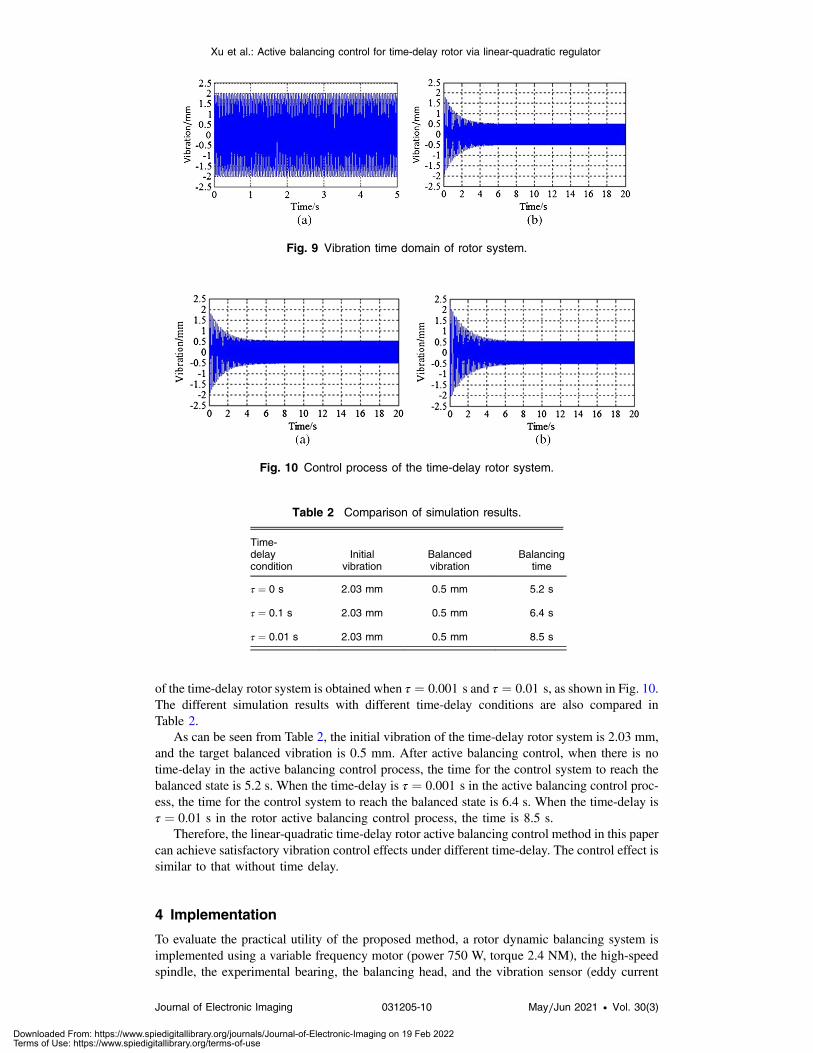
of the time-delay rotor system is obtained when τ ¼ 0.001 s and τ ¼ 0.01 s, as shown in Fig. 10.The different simulation results with different time-delay conditions are also compared inTable 2.
As can be seen from Table 2, the initial vibration of the time-delay rotor system is 2.03 mm,and the target balanced vibration is 0.5 mm. After active balancing control, when there is notime-delay in the active balancing control process, the time for the control system to reach thebalanced state is 5.2 s. When the time-delay is τ ¼ 0.001 s in the active balancing control proc-ess, the time for the control system to reach the balanced state is 6.4 s. When the time-delay isτ ¼ 0.01 s in the rotor active balancing control process, the time is 8.5 s.
Therefore, the linear-quadratic time-delay rotor active balancing control method in this papercan achieve satisfactory vibration control effects under different time-delay. The control effect issimilar to that without time delay.
4 Implementation
To evaluate the practical utility of the proposed method, a rotor dynamic balancing system isimplemented using a variable frequency motor (power 750 W, torque 2.4 NM), the high-speedspindle, the experimental bearing, the balancing head, and the vibration sensor (eddy current
Fig. 9 Vibration time domain of rotor system.
Fig. 10 Control process of the time-delay rotor system.
Table 2 Comparison of simulation results.
Time-delaycondition
Initialvibration
Balancedvibration
Balancingtime
τ ¼ 0 s 2.03 mm 0.5 mm 5.2 s
τ ¼ 0.1 s 2.03 mm 0.5 mm 6.4 s
τ ¼ 0.01 s 2.03 mm 0.5 mm 8.5 s
Xu et al.: Active balancing control for time-delay rotor via linear-quadratic regulator
Journal of Electronic Imaging 031205-10 May∕Jun 2021 • Vol. 30(3)
Downloaded From: https://www.spiedigitallibrary.org/journals/Journal-of-Electronic-Imaging on 19 Feb 2022Terms of Use: https://www.spiedigitallibrary.org/terms-of-use
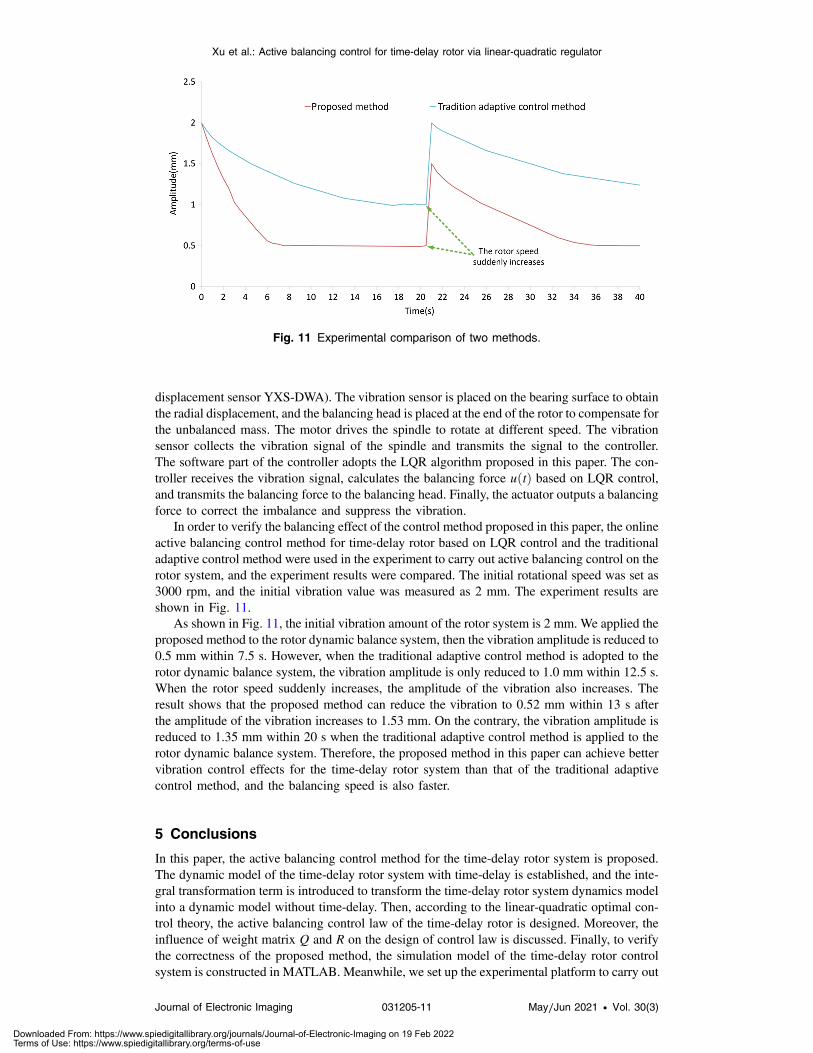
displacement sensor YXS-DWA). The vibration sensor is placed on the bearing surface to obtainthe radial displacement, and the balancing head is placed at the end of the rotor to compensate forthe unbalanced mass. The motor drives the spindle to rotate at different speed. The vibrationsensor collects the vibration signal of the spindle and transmits the signal to the controller.The software part of the controller adopts the LQR algorithm proposed in this paper. The con-troller receives the vibration signal, calculates the balancing force uðtÞ based on LQR control,and transmits the balancing force to the balancing head. Finally, the actuator outputs a balancingforce to correct the imbalance and suppress the vibration.
In order to verify the balancing effect of the control method proposed in this paper, the onlineactive balancing control method for time-delay rotor based on LQR control and the traditionaladaptive control method were used in the experiment to carry out active balancing control on therotor system, and the experiment results were compared. The initial rotational speed was set as3000 rpm, and the initial vibration value was measured as 2 mm. The experiment results areshown in Fig. 11.
As shown in Fig. 11, the initial vibration amount of the rotor system is 2 mm. We applied theproposed method to the rotor dynamic balance system, then the vibration amplitude is reduced to0.5 mm within 7.5 s. However, when the traditional adaptive control method is adopted to therotor dynamic balance system, the vibration amplitude is only reduced to 1.0 mm within 12.5 s.When the rotor speed suddenly increases, the amplitude of the vibration also increases. Theresult shows that the proposed method can reduce the vibration to 0.52 mm within 13 s afterthe amplitude of the vibration increases to 1.53 mm. On the contrary, the vibration amplitude isreduced to 1.35 mm within 20 s when the traditional adaptive control method is applied to therotor dynamic balance system. Therefore, the proposed method in this paper can achieve bettervibration control effects for the time-delay rotor system than that of the traditional adaptivecontrol method, and the balancing speed is also faster.
5 Conclusions
In this paper, the active balancing control method for the time-delay rotor system is proposed.The dynamic model of the time-delay rotor system with time-delay is established, and the inte-gral transformation term is introduced to transform the time-delay rotor system dynamics modelinto a dynamic model without time-delay. Then, according to the linear-quadratic optimal con-trol theory, the active balancing control law of the time-delay rotor is designed. Moreover, theinfluence of weight matrix Q and R on the design of control law is discussed. Finally, to verifythe correctness of the proposed method, the simulation model of the time-delay rotor controlsystem is constructed in MATLAB. Meanwhile, we set up the experimental platform to carry out
Fig. 11 Experimental comparison of two methods.
Xu et al.: Active balancing control for time-delay rotor via linear-quadratic regulator
Journal of Electronic Imaging 031205-11 May∕Jun 2021 • Vol. 30(3)
Downloaded From: https://www.spiedigitallibrary.org/journals/Journal-of-Electronic-Imaging on 19 Feb 2022Terms of Use: https://www.spiedigitallibrary.org/terms-of-use

the experiments. The results show that the method can effectively suppress the vibration of thetime-delay rotor system under different time-delay.
Acknowledgments
This research was funded by the National Key Research and Development Plan of China(No. 2018Y FB2000505), Nation Nature Science Foundation of China (No. 61806067), andthe Key Research and Development Project of Anhui Province (No. 201904A06020024).
References
1. A. Shrivastava and A. R. Mohanty, “Identification of unbalance in a rotor system usinga joint input-state estimation technique,” J. Sound Vibr. 442(3), 414–427 (2019).
2. K. Ding et al., “Vibration investigation of rotor system with unbalance and blade-casingrubbing coupling faults,” J. Vibroeng. 22(2), 353–365 (2020).
3. Z. C. Qiu, C. Li, and X. M. Zhang, “Experimental study on active vibration control for akind of two-link flexible manipulator,”Mech. Syst. Signal Process. 118(March 1), 623–644(2019).
4. W. Zhongbo, M. Chuan, and Z. Changsheng, “Current compensation control of multiplefrequency vibrations of the rotor in active magnetic bearing high speed motors,” Proc.CSEE 38(1), 275–284 (2018).
5. J. Xu and X. Sun, “A multi-directional vibration isolator based on quasi-zero-stiffnessstructure and time-time-delay active control,” Int. J. Mech. Sci. 100, 126–135 (2015).
6. F. Raufmehr and M. Rezaei, “Fuzzy logic-based scalable video rate control algorithm forhigh-delay applications of scalable high-efficiency video coding,” J. Electron. Imaging27(4), 043013 (2018).
7. S. Heindel, F. Becker, and S. Rinderknecht, “Unbalance and resonance elimination withactive bearings on a Jeffcott rotor,” Mech. Syst. Signal Process. 85(February), 339–353(2017).
8. A. Mironchenko and F. Wirth, “Input-to-state stability of time-delay systems: criteriaand open problems,” in IEEE 56th Annu. Conf. Decis. and Control (CDC), Melbourne,pp. 3719–3724 (2017).
9. H. Zheng et al., “Shaft longitudinal vibration active control based on the adaptive method,”J. Vibr. Shock 37(4), 203–207, 218 (2018).
10. N. A. Saeed and W. A. El-Ganaini, “Time-time-delay control to suppress the nonlinearvibrations of a horizontally suspended Jeffcott-time-delay rotor system,” Appl. Math.Modell. 44(April), 523–539 (2017).
11. L. Wang et al., “Hybrid time-variant reliability estimation for active control structures underaleatory and epistemic uncertainties,” J. Sound Vibr. 419, 469–492 (2018).
12. H. L. Hu and L. D. He, “Control of critical speed vibrations of a single-span rotor by a rotordynamic vibration absorber at different installation positions,” J. Mech. Sci. Technol. 31(5),2075–2081 (2017).
13. D. S. Huang, J. Q. Zhang, and Y. L. Liu, “The PID semi-active vibration control on non-linear suspension system with time delay,” Int. J. Intell. Transp. Syst. Res. 16(7), 1–13(2017).
14. J. Zhang et al., “Robust model predictive control for uncertain positive time-delay systems,”Int. J. Control Autom. Syst. 17(2), 307–318 (2019).
15. H. Li, G. Xu, and G. Xu, “Mechanical vibration monitoring system based on wireless sensornetwork,” Int. J. Online Eng. 14(6), 126–137 (2018).
16. Z. Wang and C. M. Mak, “Application of a movable active vibration control system ona floating raft,” J. Sound Vibr. 414, 233–244 (2018).
17. S. Hongxin et al., “Time delay compensation for the active cable vibration control usinggiant magnetostrictive actuators,” J. Vibr. Shock 36(14), 208–215 (2017).
18. W. H. Kwon and A. E. Pearson, “Feedback stabilization of linear systems with time-delaycontrol,” IEEE Trans. Autom. Control 25(2), 266–269 (1980).
Xu et al.: Active balancing control for time-delay rotor via linear-quadratic regulator
Journal of Electronic Imaging 031205-12 May∕Jun 2021 • Vol. 30(3)
Downloaded From: https://www.spiedigitallibrary.org/journals/Journal-of-Electronic-Imaging on 19 Feb 2022Terms of Use: https://www.spiedigitallibrary.org/terms-of-use

19. H. Im, H. H. Yoo, and J. Chung, “Dynamic analysis of a BLDC motor with mechanical andelectromagnetic interaction due to air gap variation,” J. Sound Vibr. 330(8), 1680–1691(2011).
20. B. Brekhna et al., “Robustness analysis of superpixel algorithms to image blur, additiveGaussian noise, and impulse noise,” J. Electron. Imaging 26(6), 061604 (2017).
Juan Xu received her PhD from Hefei University of Technology, Hefei, China, in 2012.Currently, she works at Hefei University of Technology. Her current research interests includevibration active control and intelligent fault diagnosis.
Yang Zhao received his BS degree in mechanical engineering from Xuzhou University ofTechnology in 2014. He received his MS degree in mechanical engineering from HefeiUniversity of Technology in 2019. His research interests include electrical control, vibrationactive control, and bearing dynamics analysis.
Zhanfeng Xu, graduated from Zhejiang University of Science and Technology in 2019. He isa graduate student majoring in mechanical and electronic engineering at Hefei University ofTechnology. He is mainly engaged in the research of vibration active control and intelligentfault diagnosis.
Benhong Zhang received his PhD from Hefei University of Technology, Hefei, China, in 2010.Currently, he is an associate professor and master supervisor of the School of Computer andInformation, Hefei University of Technology. He is mainly engaged in vibration active controland distributed control.
Xu et al.: Active balancing control for time-delay rotor via linear-quadratic regulator
Journal of Electronic Imaging 031205-13 May∕Jun 2021 • Vol. 30(3)
Downloaded From: https://www.spiedigitallibrary.org/journals/Journal-of-Electronic-Imaging on 19 Feb 2022Terms of Use: https://www.spiedigitallibrary.org/terms-of-use