Activated atmosphere case hardening of steels
127
i Activated atmosphere case hardening of steels by Xiaolan Wang A Dissertation Submitted to the Faculty of the WORCESTER POLYTECHNIC INSTITUTE in partial fulfillment of the requirements for the Degree of Doctor of Philosophy in Material Science and Engineering Dec 2011 Approved: ___________________ Prof. Richard D. Sisson Jr, Advisor Mr. Zbigniew Zurecki, Co-advisor Prof. Diran Apelian, Committee Member Prof., Makhlouf M. Makhlouf, Committee Member Prof. Jianyu Liang, Committee Member
-
Upload
trankhuong -
Category
Documents
-
view
222 -
download
0
Transcript of Activated atmosphere case hardening of steels

i
Activated atmosphere case hardening of steels
by
Xiaolan Wang
A Dissertation
Submitted to the Faculty
of the
WORCESTER POLYTECHNIC INSTITUTE
in partial fulfillment of the requirements for the
Degree of Doctor of Philosophy
in
Material Science and Engineering
Dec 2011
Approved: ___________________
Prof. Richard D. Sisson Jr, Advisor
Mr. Zbigniew Zurecki, Co-advisor
Prof. Diran Apelian, Committee Member
Prof., Makhlouf M. Makhlouf, Committee Member
Prof. Jianyu Liang, Committee Member

ii
ACKNOWLEDGMENTS
I would like to thank my advisor Professor Richard D. Sisson, Jr. for providing me
the opportunity to work on this project and for his help, encouragement, and advice
throughout this project as well as others to allow me to be where I am today.
I would like to thank Z. Zurecki for support, assistance, valuable suggestions and
overall guidance throughout this study. I’d like to gratefully acknowledge the member
companies of the Center for Heat Treating Excellence (CHTE), Air Products and
Chemical to fund this project
My sincere thanks go to my thesis committee members Professor Diran Apelian,
Professor Makhlouf M. Makhlouf, and Professor Jianyu Liang for encouragement,
critical comments and stimulus questions. I thank my class professors Professor Satya S.
Shivkumar, Mohammed Maniruzzaman, Boquan Li and Christopher A. Brown for
teaching me fundamental knowledge.
I would like to thank John Green and Robert Knorr for all of their invaluable
assistance and suggestions throughout this study. I would also like to thank Rita
Shilansky for all of her time and support.
Lastly, I thank my friends and family for all of their help to get me where I am.

iii
ABSTRACT
Case hardening, a process which includes a wide variety of techniques, is used to
improve the wear resistance, by diffusing carbon (carburization), nitrogen (nitriding)
and/or boron (boriding) into the outer layer of the steel at high temperature, and then heat
treating the surface layer to the desired hardness without affecting the softer, tough
interior of the part.
In this research, a nitrogen-hydrocarbon gas mixture was used as the process
atmosphere for carburizing steels. It can offer a cost and part quality alternative to the
conventional endothermic atmosphere and vacuum processes. It can hold the promise for
matching the quality of work parts processed in vacuum furnace, i.e. eliminating the
intergranular oxidation which normally occurs in the endogas atmosphere. The process
control of nitrogen-hydrocarbon atmosphere is also investigated in the research. Modified
shim stock method is used to measure the carbon pickup and constant carbon flux
modeling tool is used afterwards to predict the carbon profile. With minimum
modification, commercially available equipment or sensors can be used to monitor non-
equilibrium process atmosphere.
Gas nitriding was also studied. For nitriding, the kinetics of the nitriding process
with hydrocarbon gases addition and electric arc discharge activation of the nitrogen
diluted ammonia atmosphere were investigated. Prior to and during the nitriding,
hydrocarbon gases were reacted with metal surface and removed oxidation layers, which
can accelerate nitriding process. Overall, nitriding with this unique gas mixture provides
an alternative to a long-hour pure ammonia nitriding with more efficient energy
utilization.
The main objective of this project is to develop the conventional, atmospheric-
pressure, low-cost surface hardening treatments for the case hardening of carbon, alloy
and stainless steel. The possibility of plasma activation of atmosphere and metal surface
to shorten processing time and save energy and time is investigated in this research. The
process atmosphere is safer, more efficient, less toxic and less flammable.

iv
TABLE OF CONTENTS
ACKNOWLEDGMENTS ................................................................................................................ ii
ABSTRACT .................................................................................................................................... iii
TABLE OF CONTENTS ................................................................................................................ iv
CHAPTER I INTRODUCTION..................................................................................................... 1
Research Objectives .................................................................................................................... 2
Research Plan .............................................................................................................................. 3
CHAPTER II LITERATURE REVIEW ........................................................................................ 6
2.1 Nitrogen-hydrocarbon atmosphere carburizing ............................................................... 6
2.2 Atmosphere nitriding ....................................................................................................... 8
2.2.1 Fundamentals of gas nitriding ........................................................................................ 8
2.2.2 Nitriding stainless steel ................................................................................................. 12
2.3 Plasma activation ........................................................................................................... 14
2.4 Erosion and wear resistance of high-alloy steel ............................................................ 18
References ................................................................................................................................. 22
CHAPTER III PUBLICATIONS ................................................................................................. 28
Paper 1:Evaluation of process control methods for nitrogen-hydrocarbon atmospheres (to be
published in Heat Treating Conference and Exposition, 2011) .................................................... 28
Paper 2: Nitrding of carbon, alloy and stainless steels by diluted ammonia (to be submitted to
International Heat Treatment and Surface Engineering) .............................................................. 49
Paper 3: Development of Low-Cost, Rapid Case Hardening Treatments for Austenitic Stainless
Steels (to be published in Heat Treating Conference and Exposition, 2011) ............................... 65
Paper 4: Evaluation of high Cr steels in cryogenic erosion environment (to be submitted to Wear)
....................................................................................................................................................... 84
CHAPTER IV RESEARCH CONCLUSIONS .......................................................................... 103
APPENDIX A Atmosphere carburizing using electric discharge-activated nitrogen-natural gas
mixtures (published in Heat Treating Conference and Exposition, Indianapolis, Indiana, Oct
2009) ............................................................................................................................................ 105

1
CHAPTER I
INTRODUCTION
Thermochemical, diffusional surface hardening is the most cost-effective method
used in automotive, heavy equipment, energy, defense, shipbuilding, and tools
manufacturing to improve surface hardness, wear resistance, fatigue life and corrosion
resistance. The most popular methods used in the industry are gas carburizing and
nitriding. But these techniques are limited by the process atmosphere and coarse control
system. For example, endothermic gas which widely used in the industrial as carburizing
gas is produced by expensive, high maintenance, low cost-efficiency endo-generator.
And, in the current manufacturing environment, more than 50% of the in-used
exothermic and endothermic atmosphere systems require replacement. For vacuum
carburizing, plasma ion nitriding and carburizing, other issues are confronted, including
high capital cost, high maintenance cost, as well as parts geometry and material selection
limited by gas flow field and quenching speed capabilities. Therefore, new techniques
and processes are needed to not only increase production rate and reduce the cost, but
also improve parts quality.
Conventional gas carburizing which uses endothermic gas as atmosphere can only
archive 0.9-1.2% carbon potential(Cp). If hydrocarbon gases(HC) are introduced to the
endogas, Cp can be increased and carburizing can be accelerated without increasing
process temperature. N2-HC or H2-HC blends have unacceptably low carburizing kinetics
if no plasma activation of HC is used. And moreover, process control methods for this
atmosphere are limited due to uncontrolled ingress of ambient air, and the nature of non-
equilibrium gas mixture. New in-situ systems must be developed to control the process.
Gas nitriding of highly alloyed and stainless steels is significantly inhibited under
atmospheric pressure operations and requires expensive and complex pre-treatments,
which use HCl, NF3, or Ni-plating. In order to eliminate the pretreatments mentioned
above, plasma activation of gases is needed in the atmospheric pressure operations.
To archive the goal of creating better processes, several approaches were
developed. Frist, cold plasma was used to activate the feed gases entering furnace. There

2
are several potential obstacles and unknowns regarding plasma activation. For example,
the reaction of metal surface to activated gas, thermochemical kinetics of carburizing
and/or nitriding with and w/o plasma activation and the effect of plasma discharge
produced methyl, cyanide and activated H2 groups on the adsorption of C and N by steel
surface. These issues have been identified in this research, and require additional research.
Our second approach is HC gas addition to ammonia, to produce transient cyanide groups
that remove the Cr2O3 barrier film on stainless steels and highly alloyed steels which
inhibit diffusion of C and N into steel surface and subsequent case hardening.
There are many potential benefits in this new low cost, cold plasma activated
process. Energy costs are reduced by eliminating the endogas generator in process. The
high CO2 (40%) content in the emission of the gas carburizing process is eliminated. The
safety and health of the operators are improved by the elimination of toxic and flammable
gases. The parts quality is improved by the elimination of intergranular oxides (IGO) in
the carburized parts. Finally the cycle time can be reduced by the use of high carbon
fluxes and potentials during the process. The cold plasma activated gases used has a
higher effective activity (i.e. Cp) and will accelerate the absorption of the carbon and/or
nitrogen into the steel. The enhanced absorption (i.e. measured flux) will allow more
rapid carburizing and nitriding, therefore reduce cycle times.
Research Objectives
This work focused on the development of the safer, more efficient process
atmosphere which can be used in case hardening the steels. The following are main
objectives:
Develop a cold (non-thermal) plasma discharge system which can activate
carburizing/nitriding atmosphere and be used as an alternative to current toxic,
highly flammable atmosphere.
Develop the experimental procedures to fully evaluate and characterize these
novel processes to compete with existing widely used process.
Investigate the possibility of atmosphere and metal surface activation to reduce
process time and save energy and time.

3
Investigate and develop process control methods for HC carburizing with
minimal modification to commercially available equipment or sensors to
monitor the non-equilibrium process atmosphere.
Develop the conventional, atmospheric-pressure, low-cost surface hardening
treatments for the case hardening of carbon, alloy and stainless steel in simple,
less toxic and less flammable N2 based atmospheres.
Research Plan
The research plan for this project is described below. The plan consists of
theoretical studies and experimental evaluations. Experimental work is focused on: (1)
atmospheric pressure carburizing in nitrogen based, low percentage hydrocarbon gases
for alloy steels; (2) low temperature atmospheric pressure nitriding in diluted ammonia
for alloy and stainless steels; (3) high temperature solution carburizing/nitriding for
stainless steels in nitrogen gas with or w/o hydrocarbon gas addition; (4) erosion wear
resistance at cryogenic temperature for hardened and as-supplied high Cr steel.
Overall, the research plan covered major part of commonly used case hardening
process and proposed an alternative by using nitrogen based diluted process gas and cold
plasma electric discharge system. More details are presented below:
1. Carburizing
1) Atmosphere carburizing using electric discharge-activated nitrogen-natural gas
mixtures (published in Heat Treating Conference and Exposition, Indianapolis,
Indiana, Oct 2009)
Multiple N2-HC blends dissociation rate
Cold Plasma Carburizing System
N2-CH4-O2 Gas reactions in atmospheric pressure furnace
Average carbon flux and activity comparison
Microhardness and no-IGO microstructure evaluation
4
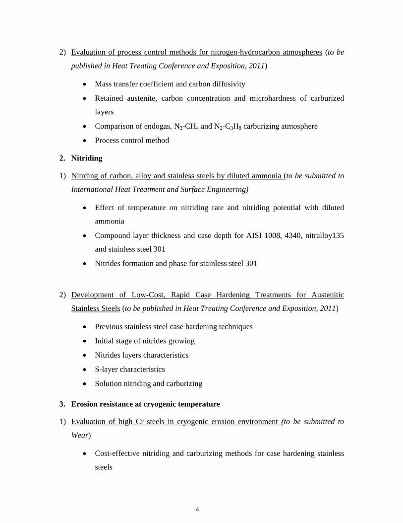
2) Evaluation of process control methods for nitrogen-hydrocarbon atmospheres (to be
published in Heat Treating Conference and Exposition, 2011)
Mass transfer coefficient and carbon diffusivity
Retained austenite, carbon concentration and microhardness of carburized
layers
Comparison of endogas, N2-CH4 and N2-C3H8 carburizing atmosphere
Process control method
2. Nitriding
1) Nitrding of carbon, alloy and stainless steels by diluted ammonia (to be submitted to
International Heat Treatment and Surface Engineering)
Effect of temperature on nitriding rate and nitriding potential with diluted
ammonia
Compound layer thickness and case depth for AISI 1008, 4340, nitralloy135
and stainless steel 301
Nitrides formation and phase for stainless steel 301
2) Development of Low-Cost, Rapid Case Hardening Treatments for Austenitic
Stainless Steels (to be published in Heat Treating Conference and Exposition, 2011)
Previous stainless steel case hardening techniques
Initial stage of nitrides growing
Nitrides layers characteristics
S-layer characteristics
Solution nitriding and carburizing
3. Erosion resistance at cryogenic temperature
1) Evaluation of high Cr steels in cryogenic erosion environment (to be submitted to
Wear)
Cost-effective nitriding and carburizing methods for case hardening stainless
steels

5
Cryogenic erosion test apparatus
Erosion response for Cr cast iron and 17-4 PH steel and with/without treated
stainless steels 304, 316L, 310, at the liquid N2 temperature (-195oC) and
room temperature(+25oC)

6
CHAPTER II
LITERATURE REVIEW
2.1 Nitrogen-hydrocarbon atmosphere carburizing
Conventional carbon-containing atmospheres used in carburizing are generated in
endothermic generators, external to heat treating furnaces and, frequently adjusted to
match process requirements by mixing hydrocarbon gases (HC) such as methane (CH4),
propane (C3H8), propylene (C3H6), acetylene (C2H2), and/or nitrogen (N2) with air.6 Since
endothermic gas with air forms hydrogen (H2), N2, and carbon monoxide (CO), with
minimal quantities of water vapor (H2O), and carbon dioxide (CO2). The conventional
atmospheres have a potential to carburize the main steel and simultaneously oxidize iron
and alloying additions, e.g. chromium (Cr), manganese (Mn), silicon (Si) or vanadium
(V). And similar oxidizing-carburizing effects are observed in alternative, dissociated
alcohol atmospheres, e.g. N2-methanol and N2-ethanol.7-9
Oxygen-free, nitrogen-hydrocarbon heat treating atmosphere has been an object of
industrial and research interest for over a quarter-century. Nitrogen-hydrocarbon
atmospheres which applied in carburizing and neutral carbon potential annealing
operations, 10-13
hold the promise for matching the quality of work parts processed in
vacuum furnace, i.e. eliminating the intergranular oxidation existed in the conventional,
endo-generated atmospheres. Compared with endothermic gas carburizing and vacuum
carburizing, there are many advantages for nitrogen-hydrocarbon atmosphere, listed in
Table 1. Moreover, N2-HC blends are safe, non-toxic/less-flammable atmospheres.
Methane alone is hardly used as carburizing gas due to the relatively high
thermochemical stability. Similar observations were made in the area of vacuum
carburizing where the initial practice of CH4 carburizing at a fairly high partial pressure
was gradually replaced by a low partial pressure carburizing in acetylene, ethylene, or
propane-hydrogen multi-component blends.14-15
This shift away from inexpensive CH4
blends is not surprising in view of low dissociation rate. 16-17

7
Table 1 Comparison of N2-HC vs. endogas/ vacuum carburizing
Criteria N2-HC vs. Endogas N2-HC vs. Vacuum
Capital and operating
cost Negligible vs. endo-generator
Negligible vs. vacuum
furnace
Atmosphere cost
Significantly less than endo if
combined with non-cryo-N2
source
Generally more than
vacuum
Atmosphere quality More consistent in composition
and flowrate Comparable
Applicability to
processing small parts
or short cycles
Minimum IGO and/or IG-
carbides Comparable
Applicability to
processing large parts
or long cycles
Capable of producing desired,
flat carbon profiles by diffusing
under low Cp
Superior because very
large vacuum furnaces are
rarely available
Operational safety Intrinsically safe (less
flammable and non-toxic) Comparable
Toxic and regulated
emissions
Significantly less polluting (no
CO/CO2) Comparable
Although occasionally used in atmospheric pressure furnaces, the N2-HC atmospheres
are, nevertheless, underutilized due to insufficiently developed process control methods.
However, the process control of nitrogen-hydrocarbon atmosphere is difficult due to the
non-equilibrium process and less precise control systems in 1-atm pressure furnace. It
involves a number of additional, sometimes uncontrollable process variables such as air
and combustible gas leakage or moisture desorption.18
For endogas carburizing, metal
coupon or metal foil or, simply, shim stock methods have been well known and used in
the conventional, equilibrium atmospheric carburizing operations for determining Cp
(carbon potential).19
Since the surface carbon concentration cannot exceed Cp, the
8
method involves a very thin steel foil and long exposure time to saturate the metal
throughout and achieve a constant carbon concentration profile across the width.
Consequently, the measurement of weight gain of the foil directly indicates atmosphere
Cp. But in N2-HC atmosphere, the situation is different due to the non-equilibrium of the
atmosphere. The surface carbon concentration is no longer a constant, becoming a time
sensitive function. Many in-situ sensors have been developed over the years to address
the challenges of process control in non-equilibrium as well as equilibrium
atmospheres.20-21
2.2 Atmosphere nitriding
2.2.1 Fundamentals of gas nitriding
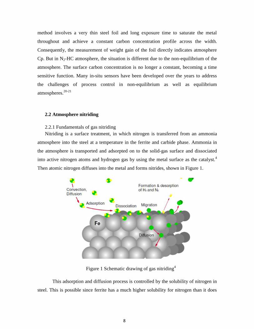
Nitriding is a surface treatment, in which nitrogen is transferred from an ammonia
atmosphere into the steel at a temperature in the ferrite and carbide phase. Ammonia in
the atmosphere is transported and adsorpted on to the solid-gas surface and dissociated
into active nitrogen atoms and hydrogen gas by using the metal surface as the catalyst.4
Then atomic nitrogen diffuses into the metal and forms nitrides, shown in Figure 1.
Figure 1 Schematic drawing of gas nitriding4
This adsorption and diffusion process is controlled by the solubility of nitrogen in
steel. This is possible since ferrite has a much higher solubility for nitrogen than it does
9
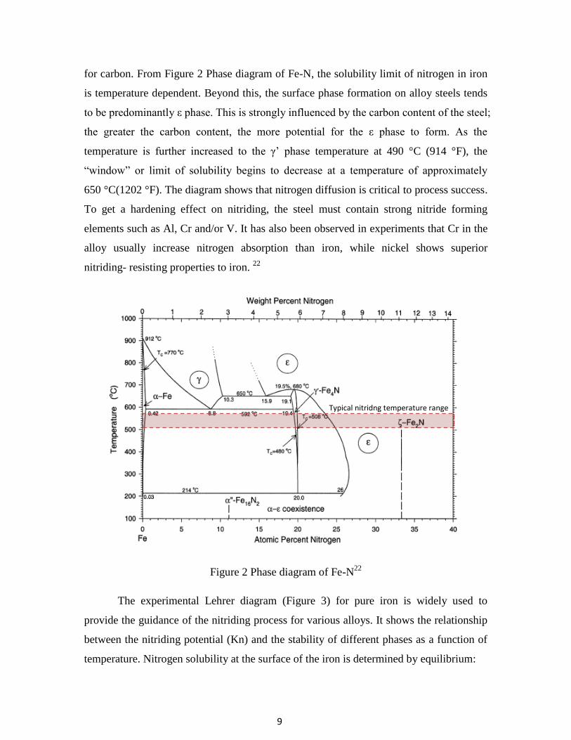
for carbon. From Figure 2 Phase diagram of Fe-N, the solubility limit of nitrogen in iron
is temperature dependent. Beyond this, the surface phase formation on alloy steels tends
to be predominantly ε phase. This is strongly influenced by the carbon content of the steel;
the greater the carbon content, the more potential for the ε phase to form. As the
temperature is further increased to the γ’ phase temperature at 490 °C (914 °F), the
“window” or limit of solubility begins to decrease at a temperature of approximately
650 °C(1202 °F). The diagram shows that nitrogen diffusion is critical to process success.
To get a hardening effect on nitriding, the steel must contain strong nitride forming
elements such as Al, Cr and/or V. It has also been observed in experiments that Cr in the
alloy usually increase nitrogen absorption than iron, while nickel shows superior
nitriding- resisting properties to iron. 22
Figure 2 Phase diagram of Fe-N22
The experimental Lehrer diagram (Figure 3) for pure iron is widely used to
provide the guidance of the nitriding process for various alloys. It shows the relationship
between the nitriding potential (Kn) and the stability of different phases as a function of
temperature. Nitrogen solubility at the surface of the iron is determined by equilibrium:
Typical nitridng temperature range
Typical nitridng temperature range

10
Hence (for dilute solution of N in Fe, Henry’s law)
where k is a temperature dependent equilibrium constant ( ),
at 700-1400K 23
) and pNH3 and pH2 are the partial pressure in the furnace atmosphere:
So, Kn can be calculated. By using Lehrer diagram generated from experimental
data, the formation of nitrides can be predicted. But since this Lehrer diagram is for pure
iron, using it to predict high alloy steel nitriding may not be accurate. Nowadays, specific
Lehrer diagram for specific alloy condition can generated by using advanced
thermodynamic software.24
Figure 3 Lehrer diagram for pure iron25

11
In the iron-nitrogen system, all the nitrides shown in Table 2 are commonly found
among the nitrids layers after the nitriding of plain-carbon and alloy steels. As we know,
ammonia is metastable and decomposes in contact with metal surface.26
For any
ammonia-hydrogen gas mixture, there is a nitriding potential or activity of nitrogen
dissolved in iron. As the ammonia content of an ammonia-hydrogen gas mixture
increases, the nitrogen content of the iron increases until the point which the nitrogen
potential reaches the equilibrium with nitrogen in γ'-Fe4N. So the microstructural of the
compound layer depends on the nitriding potential to form either a mono (γ'-Fe4N) or
biphase ( ε+ γ') at a given temperature.27
Table 2 Phase in the iron-nitrogen system27
Phase Composition Wt. %(At. %)N Interstitial atoms
per 100 Fe atoms
Bravais
Lattice
Ferrite (α) Fe 0.10(0.40) - B.C.C.
Austenite (γ) Fe 2.8(11) 12.4 F.C.C.
Martensite (α’) Fe 2.6(10) 11.1 B.C. tetrag.
γ’ Fe4N1-x 5.9(20) 25 Cubic
ε Fe2(N,C)1-z 4.5-11.0(18-32) 22-49.3 Hexagonal
ζ Fe2N 11.4(33.3) 50 Orthorhombic
As we know, the nitriding process often takes an extremely long time. So in order
to accelerate the process, numerous investigations have been done.28-33
It has been
reported, cathode sputtering (voltage: 700–1350 V, current density: 1–4 A/cm2, for
10 min) activated the steel surface, shortened the nitride nucleation time and produced a
larger nitriding case during same process time.28, 29
The roughness of parts surface
influenced the nitriding results, mirror polished samples (Ra = 0.05) exhibited high
hardness and larger case depth after plasma nitriding compared to the rough polished
(Ra = 0.075), machined (Ra = 0.47) and ground (Ra = 1.02) samples, due to the presence
of ferrite on the surface which facilitated diffusion of nitrogen into the sample during the
following nitriding.30
Using an activator (1% aqueous HCl) in pretreatment step to create

12
an uniform nitrided layer has also been investigated.31
Some research has been done in
the effect of residual stress in nitriding, samples with low values of residual stress gave
higher penetration depths of nitrogen, compared to samples with high levels of residual
stress.32
It was also claimed 10.5 +/- 0.5min pre-oxidation in water steam increased 30%-
50% nitriding rates.33
In patent US 2007/0204934 A1, 34
it claimed with some additional
active hydrocarbon gas in the ammonia, HCN can formed and it can improve the
uniformity of nitriding treatment and the nitrogen penetrating. This treatment will shorten
the nitriding time to archive the same case depth. El-Rahman35
also investigated the
effects of high percentage C2H2 used in r.f. plasma carbonitriding for austenitic stainless
steel. CH4 is used in plasma immersion ion implantation X5CrNi189 steel (AISI 304
stainless steel). The results show both improvements in larger case depth and higher
hardness. 36
2.2.2 Nitriding stainless steel
In 2010, the production of stainless steel is 30.7 million tons worldwide. And
among that, 57.7% is 300 series austenitic stainless steels.37
Austenitic stainless steels are
critical in the modern economies with applications ranging from food processing and
cryogenic machinery to medical implants and aerospace instrumentation. Toughness,
resistant to low-temperature embrittlement and corrosion resistance are the major
properties we targeted in the applications. 38
Case hardening was found to be effective to improve the stainless steel hardness
and wear resistance. Combined with corrosive surface treatments or low-pressure, direct
plasma-ion discharges, case hardening stainless steel is possible, but inhibited in simple
atmospheric-pressure furnaces. Common practice includes surface treatments in carbon
and/or nitrogen source gases and is usually performed with temperatures around 500oC
(932oF).
39 However, stainless steel raises two problems: First, the native passive layer
may cause problem for nitrogen and carbon atoms to penetrate; second, chromium reacts
with nitrogen and carbon and forms nitrides which will cause loss of corrosion resistance.
Many processes have been developed in recent decades to overcome those
obstacles.40-55
Three, largely proprietary processes are best known in the US at present:
ion-nitriding and carburizing in partial vacuum, plasma furnaces40-42
; low-temperature
(350oC-550
oC) nitriding involving metal surface pre-etching using corrosive and toxic

13
gases 43-48
, and solution nitriding at high temperatures assuring the presence of austenitic
phase during diffusion treatment (1050oC-1200
oC)
49-51. It is desired to treat and harden
the surface using nitriding, an inexpensive, thermochemical-diffusional process well
proven in the field of low-alloy and carbon steels. Unfortunately, the passive oxide films
forming on metal surface act as dense diffusion barriers preventing the conventional
nitriding. Many methods have been developed to date in order to overcome the problem
of passive oxide films. Thus, the metal surface could be dry-etched at elevated
temperatures in halide gases such as hydrochloric acid (HCl) 52
or nitrogen trifluoride
(NF3) 53
, or low-pressure (vacuum furnace) nitriding with plasma ion glow discharges
were used to activate steel surface40-42
. The methods require a prolonged, multi-hour
processing time, significant capital, safety equipment, and maintenance expenditures.
Due to the complex surface activation steps before the process or low pressure which
normally used, the hardening step is often expensive.
In 1985, Zhang and Bell observed that at temperatures below 450oC, large
quantities of nitrogen or carbon can be dissolved in the stainless steel to form expanded
austenite phase (S-phase) which can improve wear resistance and corrosion resistance of
the steel.43
But this technique often requires expensive plasma/implantation based
techniques which have limited production capacity. Expanded austenite without nitrides
can be obtained when high amounts of atomic nitrogen (20 to 30 at.%) are dissolved in
stainless steel at temperatures below 450oC. The nitrogen atoms are presumed to exist in
the octahedral interstices of the f.c.c. lattice.44-45
Expanded austenite is metastable and
tends to form chromium nitrides. The high content of N is obtained, because of the
relatively strong affinity of Cr atoms for N atoms, to short range ordering of Cr and N.
Due to the low mobility of Cr atoms, compared to N atoms, at low treatment
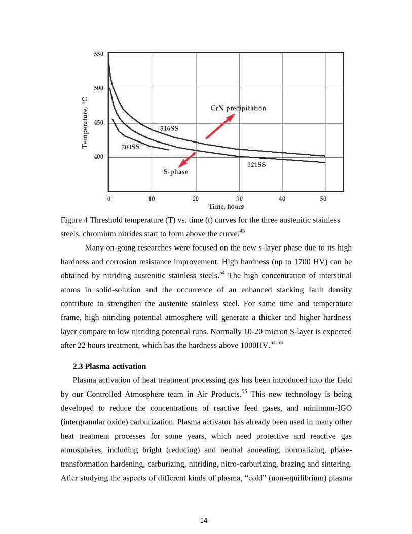
temperatures, chromium nitrides do not precipitate until after long exposure times,45
as
shown in Figure 4.
14
Figure 4 Threshold temperature (T) vs. time (t) curves for the three austenitic stainless
steels, chromium nitrides start to form above the curve.45
Many on-going researches were focused on the new s-layer phase due to its high
hardness and corrosion resistance improvement. High hardness (up to 1700 HV) can be
obtained by nitriding austenitic stainless steels.54
The high concentration of interstitial
atoms in solid-solution and the occurrence of an enhanced stacking fault density
contribute to strengthen the austenite stainless steel. For same time and temperature
frame, high nitriding potential atmosphere will generate a thicker and higher hardness
layer compare to low nitriding potential runs. Normally 10-20 micron S-layer is expected
after 22 hours treatment, which has the hardness above 1000HV.54-55
2.3 Plasma activation
Plasma activation of heat treatment processing gas has been introduced into the field
by our Controlled Atmosphere team in Air Products.56
This new technology is being
developed to reduce the concentrations of reactive feed gases, and minimum-IGO
(intergranular oxide) carburization. Plasma activator has already been used in many other
heat treatment processes for some years, which need protective and reactive gas
atmospheres, including bright (reducing) and neutral annealing, normalizing, phase-
transformation hardening, carburizing, nitriding, nitro-carburizing, brazing and sintering.
After studying the aspects of different kinds of plasma, “cold” (non-equilibrium) plasma

15
discharge injectors was chosen for a number of technical-economic factors including: [1]
convenient retrofitting of existing heat treatment furnaces, [2] negligible power
consumption, [3] long electrode life, and [4] chemical selectivity preventing an undesired
pyrolysis of feedstock stream. By operating at 1-atm pressure, the processing gases
passed through electrical plasma, and were activated to the point at which they may react
inside furnace with metal surface at reduced concentrations and/or temperatures, with
more cost-effective, alternative compositions, and/or faster than in the conventional
practice. Cold plasma systems convert electrical energy into chemical activation and gas
heating that is consumed into the furnace. Considering all aspects, cold plasma (current:
10-1
A) was selected for the metal experiments (Figure 5).
Figure 5 Non-thermal (cold) plasma and thermal plasma 57
Figure 6 Photos of plasma arc distribution inside injector at selected flowrate

16
A series of gas stream-activating, cold-plasma injectors have been made during
the recent few years.56
The injectors comprise two high voltage electrodes positioned
across the stream of gas directed from gas supply into heat treating furnace. A DC or AC
source-powered electric discharge was applied between these electrodes ionizes, partially
dissociates and converts the gas molecules on their way into the furnace. A high-voltage,
low-amperage and low power supply is used (typically below 1 kW), which forms a cold
discharge combining self-pulsed, non-equilibrium arc and glow plasma modes inside the
passing gas stream, shown in Figure 6. The low thermal energy of the discharge assures
long electrode lifetime and prevents gas pyrolysis and sooting. Numerous long- and
short-lived, equilibrium and non-equilibrium gas products are formed in the N2-NH3 or
N2- hydrocarbon blend passing the discharge.
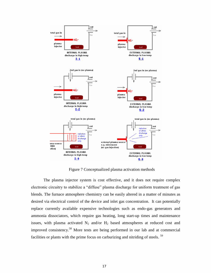
Several conceptualized activation methods are proposed to be the suitable way to
inject the activated gas, shown in Figure 7, internal or external activation with a part or
whole gas blend injected through the plasma. Several of them have been tried in this
research.
The plasma activation injector is capable of activating the furnace atmospheres
within a few minutes without any prior preparation time. The hot furnace atmosphere is
“conducive” to the radical lifetime/transport and further conversion of the unstable
species generated by plasma. In Figure 8, 12% NH3 (diluted by N2) gas was activated by
AC and DC plasma at 525oC. After activation, more NH3 dissociated into N2 and H2, and
H2 in the furnace increased 200-300% compare to non-activated NH3.
17
Figure 7 Conceptualized plasma activation methods
The plasma injector system is cost effective, and it does not require complex
electronic circuitry to stabilize a “diffuse” plasma discharge for uniform treatment of gas
blends. The furnace atmosphere chemistry can be easily altered in a matter of minutes as
desired via electrical control of the device and inlet gas concentration. It can potentially
replace currently available expensive technologies such as endo-gas generators and
ammonia dissociators, which require gas heating, long start-up times and maintenance
issues, with plasma activated N2 and/or H2 based atmospheres at reduced cost and
improved consistency.58
More tests are being performed in our lab and at commercial
facilities or plants with the prime focus on carburizing and nitriding of steels. 59

18
Figure 8 Residue NH3 and H2 concentration after plasma activation
2.4 Erosion and wear resistance of high-alloy steel
Growing industrial demand is noted for recycling polymers, rubbers, and
electronic waste, as well as contamination-free processing of foods and bioactive
materials via comminution and fine pulverizing.60
Cryogenic temperature milling and
grinding, possibly the most suitable comminution techniques, may require further
improvements to meet this demand. Many researches have been done to enhance the
erosion and abrasion wear-life of mill components. 61-64
Improving wear resistance of
cryo-mills is expected to reduce operating costs, increase productivity and, in the case of
bioactive food stock products, and reduce contamination, i.e. enhance customers’
acceptance of cryogenic milling.
Dry erosion has been assumed here as the predominant wear mechanism attacking
mill components during the cryo-pulverizing. There are very significant differences

19
between materials in their response to erosion depending on, among the other factors,
erosive particle impingement angle, kinetic energy, size, shape, hardness and process
temperature. Erosion of the steel depends on many aspects, the material properties, and
structures, physical and chemical properties of erodent particles, condition and
environment. On ductile materials the impacting particles cause severe, localized plastic
strain to occur that eventually exceeds the strain to failure of the deformed material. On
brittle materials, the force of the erodent particles causes cracking and chipping off of
microsize pieces.65-66
Many case hardening treatments, such as nitriding67
, carburizing68
,
nitrocarburizing67,69
and boronizing70
may improve wear resistance on the surface by
forming a thin, hard case, with the supporting bulk material containing the required
mechanical properties.
Erosion of the steel depends on many aspects, the material properties, and
structures, physical and chemical properties of erodent particles, condition and
environment. On ductile materials the impacting particles cause severe, localized plastic
strain to occur that eventually exceeds the strain to failure of the deformed material. On
brittle materials, the force of the erodent particles causes cracking and chipping off of
micro-size pieces.65
The erosion resistance of annealed elemental metals increased with hardness. But
greater hardness does not result in increased erosion wear resistance. Hardness is usually
has no effect or a negative effect, as shown in Figure 9. At both low and high
impingement angle, high hardness steel has more severe erosion than low hardness
aluminum. The explanation of this phenomenon is that the mechanism of erosion wear is
different for high and low hardness materials. High hardness metals often tend to
generate more microcracking and surface fatigue, that makes metal surface more easily to
fall off by erosion particles. In the other hand, softer metals suffered more microcutting
and extrusion of material, which still attached to the base metals, so the volume% lost
may be even smaller than harder metals.66

20
Figure 9 Relative erosion resistance at impact angles of (a) 15o and (b) 90
o versus
hardness of different materials. (for pure metals: quartz sand of 0.4 to 0.6 mm particle
size, v=82m/s and for steels: silicon carbide of 0.6 to 1mm particle size, v=30m/s)27
The mechanical properties of the metals have great influence on erosion
resistance. Ductility, strain hardening, “malleability”, and thermal properties are more
important, than hardness, toughness, and strength. Higher ductility generally results in
lower erosion rates. Higher strength and hardness can result in significantly greater
erosion occurring. The effect of ductility on the erosion rate of 304 stainless steel is
shown in Figure 10. It can be seen that the less ductile, as-rolled steel has a higher
erosion rate than the annealed steel.

21
Figure 10 Erosion rate for 304 stainless steel versus erodent particle weight 67
Figure 11 Erosion rate of steel versus test temperature, (a) 304 stainless steel, (b) 310
stainless steel, (c) 17-4 ph stainless steel 67
Many tests have been done on the high temperature erosion properties, as shown
in Figure 16. 304 and 310 stainless steel at low erosion angle, did not change much until
the temperature reach 400oC and then followed by a rapidly increase; but at high angle, a
22
minimum occur at 400oC. Rarely literature can be found which discussed the erosion
properties at cryogenic temperature. But as the trend shown on graphs, we can expect
higher erosion rate at cryo temperature, and even a significant increase below the
ductility to brittle transformation temperature (DBTT).
References
1. “Surface Hardening of Steels”, key to metals website
2. O. Karabelchtchikova, R.D. Sisson, Jr., S.A. Johnston, H. DaCosta,
“Thermodynamic and Kinetic Aspects of Endothermic Carburizing Atmosphere
with Natural Gas Enrichment”, Proceedings MS & T/HTS' 2007, Detroit,
Michigan, Sept. 16-20, 2007.
3. “Practical Nitriding and Ferritic Nitrocarburizing”, ASM International, 2003
4. “Cast steel: gas nitriding”, key to metals website
5. J.R. Davis, “Surface Engineering for Corrosion and Wear Resistance”, ASM
International, 2001
6. R.L. Davis et al, U.S. Patent 4,049,473
7. An, X. et al, “A study of internal oxidation in carburized steels by glow discharge
optical emission spectroscopy and scanning electron microscopy”,
Spectrochimica Acta Part B 58 (2003) 689–698
8. Chatterjee-Fisher, R., “Internal Oxidation During Carburizing and Heat Treating”,
Metallurgical Transactions Vol. 9A, November 1978, pp.1553-1560
9. Asi, O., et al, “The relationship between case depth and bending fatigue strength
of gas carburized SAE 8620 steel”, Surface & Coatings Technology 201 (2007),
pp. 5979–5987
10. Kaspersma, J.H., and Shay, R.H., “ Carburization and Gas Reactions of
Hydrocarbon-Nitrogen Mixtures at 850 ℃ and 925 ℃ ” , Metallurgical
Transactions B, Vol. 13B, June 1982, pp. 267-273.

23
11. Estrin, B.M, et al, “Carburizing in a nitrogen-based mixture with additives of pure
methane”, Metallovedenie i Termicheskaya Obrabotka Metallov, No. 5, pp. 26-29,
May, 1984
12. Connery, K. and Ho, S., “Optimization of Oxygen-free Heat Treating”, Proc. of
the 24th ASM Heat Treating Society Conf., September 17-19, 2007, COBO
Center, Detroit, Michigan, USA
13. Baldo et al, U.S. Patent 4,992,113
14. Tsuji, S., et al, “Vacuum Carburizing of Low Carbon Steel with Methane”, Trans.
of the Japan Institute of Metals, Vol. 28, No.1 (1987), pp. 48-56
15. Gorockiewicz , R., et al, “The Benefits of Using 3 Gas Mixture Low Pressure
Carburizing (LPC) for High Alloy Steels”, Proc. of the 24th ASM Heat Treating
Society Conf., September 17-19, 2007, COBO Center,Detroit, Michigan, USA
16. Shah, N., et al, “Hydrogen Production by Catalytic Decomposition of Methane”,
Energy & Fuels, 2001, 15, 1528-1534
17. Khan, R.U., et al, “Pyrolysis of propane under vacuum carburizing conditions: An
experimental and modeling study”, J. Anal. Appl. Pyrolysis 81 (2008) 148–156
18. Herring, D.H., “Furnace atmosphere analysis by the shim stock method”,
Industrial Heating, Sept (2004)
19. P. Beuret, U.S. Patent 5,064,620
20. L.G. Chedid et al, U.S. Patent 7,068,054
21. Winter, K.M., “A Guide to Better Atmosphere Carburizing Using Both Dynamic
and Equilibrium-Based Measurements”, Industrial Heating, Oct.(2008)
22. G.E. Totten, M.A.H. Howes, Steel heat treatment handbook, p722-730, 1997
23. E.J. Mittemeijer and J.T. Slycke, “Chemical potentials and activities of nitrogen
and carbon imposed by gaseous nitriding and carburising atmospheres”, Surface
Engineering 12(2), 1996
24. Y. Mei, R. Sisson, “Carbonitriding and Subcritical/Ferric Nitrocarburizing”,
CHTE report, 2010

24
25. L. Maldzinski, “New possibilities for controlling gas nitriding process by
simulation of growth kinetics of nitride layers”, Surface Engineering, 1999
26. N. Shohoji, T. Marcelo and M. Katsura, “Influence of metastable species (non-
graphitic carbon and ammonia gas) in the reactants on the composition of the
reaction product (carbide, carbonitride and nitride)”, Solid State Ionics, Volume
38, Issues 3-4, Pages 187-194 , 1990
27. D.H. Jack, “Carbides and Nitrides in Steel, Materials Science and Engineering”,
1973
28. J. Baranowska, K. Szczeci ski and M. Wysiecki, “Cathode sputtering as a pre-
treatment for gas nitriding”, Vacuum, Vol. 63, Issue 4, 2001
29. J. Baranowska and M. Wysiecki, “Influence of surface pretreatment on case
formation during gaseous nitriding”, Surface and Coatings Technology, Vol. 125,
Issues 1-3, 2000
30. G.P. Singha, and etc., “Effect of surface roughness on the properties of the layer
formed on AISI 304 stainless steel after plasma nitriding”, Surface and Coatings
Technology, Vol. 200, Issues 20-21, 2006
31. W.D. Jentzsch and S. Bohme, “Investigations on Nitride Layer Formation at the
Iron Surface during Gas Nitriding”, Crystal Research and Technology, Vol. 14,
Issue 5, 1978
32. T.K. Hirsch, A.S. Rocha, F.D. Ramos, and T.R. Strohaecker, “Residual Stress-
Affected Diffusion during Plasma Nitriding of Tool Steels”, Metallurgical and
Materials Transactions A, Vol. 35, No. 11, 2004
33. R. Yang and T. Hu, “Study of the Gas Nitriding Catalyzed by Pre-oxidation”, Hot
Working Technology, Vol. 4, 1996
34. P.N. Kogyo K.K., “Method for activating surface of metal member”, Patent
2007/0204934 A1, 2007
35. A.M. Abd El-Rahman and etc., “Effect of N2 to C2H2 ratio on r.f. plasma surface
treatment of austenitic stainless steel, Surface and coatings technology”, vol.183,
p268-274, 2004

25
36. C. Blawert and etc., “Characterisation of duplex layer structures produced by
simultaneous implantation of nitrogen and carbon into austenitic stainless steel
X5CrNi189”, Surface and coatings technology, vol.128, p219-225, 2000
37. ISSF announces global stainless steel output figure for 2010,
http://www.worldstainless.org/News/Media+releases/Stainless+steel+production+
in+2010.htm, March, 2011
38. G. Coates, and D. Jenkinson, What is Stainless Steel?, Nickel Institute Website.
39. H. Du and J. Agren, “Gaseous Nitriding Iron - Evaluation of Diffusion Data of N
in γ’ and ε Phases”, Solid Phase Transformations, 1994
40. R. Wei, , J.J. Vajo, J.N. Matossian, P.J. Wilbur, J.A. Davis, D.L. Williamson and
G.A. Collins, “A comparative study of beam ion implantation, plasma ion
implantation and nitriding of AISI 304 stainless steel”, Surface and Coatings
Technology, Volume 83, Issues 1-3, September 1996, Pages 235-242
41. C. Blawert, A. Weisheit, B.L. Mordike and R.M. Knoop, “Plasma immersion ion
implantation of stainless steel: austenitic stainless steel in comparison to
austenitic-ferritic stainless steel”, Surface and Coatings Technology, Volume 85,
Issues 1-2, 1 November 1996, Pages 15-27
42. G. A. Collins, R. Hutchings, K. T. Short, J. Tendys, X. Li and M. Samandi,
“Nitriding of austenitic stainless steel by plasma immersion ion implantation” ,
Surface and Coatings Technology, Volumes 74-75, Part 1, September 1995, Pages
417-424
43. Z.L. Zhang, T. Bell, “Structure and corrosion resistance of plasma nitrided
stainless stee”l. Surf. Eng. 1 (2), 1985
44. T. Christiansen, and M. A.J. Somers, “Characterization of low temperature
surface hardened stainless steel”, Struers Journal of Materialography, Sept., 2006
45. T. Bell and C.X. Li, “Stainless Steel: Low-Temperature Nitriding and
Carburizing”, Advanced Materials & Processes, Volume 160, Issue 6, 2002
46. J. Buhagiar, X. Li, H. Dong, “Formation and microstructural characterisation of
S-phase layers in Ni-free austenitic stainless steels by low-temperature plasma
surface alloying”, Surface and Coatings Technology, Volume 204, Issue 3, 25
October 2009, Pages 330-335
26
47. L.C. Gontijo, R. Machado, E.J. Miola, L.C. Casteletti, N.G. Alcântara and P.A.P.
Nascente, “Study of the S phase formed on plasma-nitrided AISI 316L stainless
steel”, Materials Science and Engineering: A, Volume 431, Issues 1-2, 15
September 2006, Pages 315-321
48. M. Tsujikawa, M. Egawa, N. Ueda, A. Okamoto, T. Sone, K. Nakata, “Effect of
molybdenum and copper on S-phase layer thickness of low-temperature
carburized austenitic stainless steel, Surface and Coatings Technology”, Volume
202, Issues 22-23, 30 August 2008, Pages 5488-5492
49. F. Schmalt, H. Berns, and R. Zaugg, “Solution Nitriding—A New High
Temperature Nitriding of Stainless Steel”, Surface Engineering Coatings and Heat
Treatments 2002: Proceedings of the 1st ASM International Surface Engineering
and the 13th IFHTSE Congress, Published: Jan 2003, Pages: 88-97
50. B. Edenhofer, “Solution Nitriding - A Cost Effective Case Hardening Process for
Stainless Steels”, ASM Heat Treating Society Conference and Exposition 2007
51. H. Berns, “Case hardening of stainless steel using nitrogen”, Industrial heating
2003, vol. 70, no5, pp. 47-50
52. P. Kochmanski and J. Nowacki, “Influence of initial heat treatment of 17-4 PH
stainless steel on gas nitriding kinetics”, Surface and Coatings Technology,
Volume 202, Issue 19, 25 June 2008, Pages 4834-4838
53. M. Tahara, H. Senbokuya, K. Kitano, T. Hayashida, “Method of carburizing
austenitic stainless steel and austenitic stainless”, U.S Patent 5,792,282
54. T. Christiansen, and M. A.J. Somers, “Low temperature gaseous nitriding and
carburising of stainless steel”, Surface Engineering, Volume 21, Numbers 5-6,
October 2005 , pp. 445-455(11)
55. R.B. Frandsen, T. Christiansen, and M. A.J. Somers; “Simultaneous surface
engineering and bulk hardening of precipitation hardening stainless steel”,
Surface and Coatings Technology, Volume 200, Issues 16-17, 2006
56. Z. Zurecki, “Heat Treating Atmosphere Activation”, Proc. of the 24th ASM Heat
Treating Society Conf., September 17-19, 2007
57. A. Fridman, “Plasma Chemistry”, Cambridge University Press, 2008
58. Z. Zurecki et al, U.S. Patent 2008/0283153

27
59. Zurecki, Z and Wang, X, “Atmosphere carburizing using electric discharge-
activated nitrogen-natural gas mixtures,” Heat Treating Conference and
Exposition, Indianapolis, Indiana, Oct 2009.
60. Air Products, Cryogenic griding, website, 2010
61. S. S. Gill, H. Singh, R. Singh and J. Singh, “Cryoprocessing of cutting tool
materials—a review”, The International Journal of Advanced Manufacturing
Technology, 48 (2009) 175-192
62. R. Singh, and K. Singh, “Enhancement of Tool Material Machining
Characteristics with Cryogenic Treatment: A Review”, Proceedings of the 2010
International Conference on Industrial Engineering and Operations Management,
Dhaka, Bangladesh, January 9 – 10, 2010
63. A.Y.L. Yong, K.H.W Seah, and M. Rahman, “Performance of Cryogenically
Treated Tungsten Carbide Tools in Milling Operation”, International Journal of
Advanced Manufacturing Technology, 32 (2007) 638-643,
64. M. Preciado, P.M. Bravo and J.M. Alegre, “Effect of low temperature tempering
prior cryogenic treatment on carburized steels”, Journal of Material Processing
Technology, 176 (2006) 41–44
65. A.V. Levy, “Gas-solid particle erosion and erosion-corrosion of metals”, Uhlig’s
corrosion handbook, (2000) 273-293,
66. E. Rodríguez, M. Flores, A. Pérez, R.D. Mercado-Solis, R. González, J.
Rodríguez, S. Valtierra, “Erosive wear by silica sand on AISI H13 and 4140
steels”, Wear, 267(2009) 2109–2115
67. G. Nivoletto, A. Tucci, L. Esposito, “Sliding wear behavior of nitrided and
nitrocarburized cast irons”, Wear 197 (1996) 38–44.
68. B.S. Suh, W.J. Lee, “Surface hardening of AISI 316L stainless steel using plasma
carburizing”, Thin Solid Film 295 (1997) 185–192.
69. D. Wen, “Erosion and wear behavior of nitrocarburized DC53 tool steel”, Wear,
268(2010) 629–636
70. N.Y. Sari, M. Yilmaz, “Investigation of abrasive + erosive wear behaviour of
surface hardening methods applied to AISI 1050 steel”, Mater. Design 27 (2006)
470–478.

28
CHAPTER III
PUBLICATIONS
This section is structured as a collection of papers – each presented as a
subsection outlined in this research.
Paper 1:Evaluation of process control methods for nitrogen-hydrocarbon
atmospheres (to be published in Heat Treating Conference and Exposition,
2011)
Abstract
Atmospheric pressure carburizing and neutral carbon potential annealing in
nitrogen containing small additions of hydrocarbon gases can offer cost and steel surface
quality alternatives to the comparable, endothermic atmosphere or vacuum operations.
An experimental program was conducted for refining real-time process control methods
in carburizing of AISI 8620 steel under N2-C3H8 blends containing from 1 to 4 vol% of
propane at 900oC and 930
oC. Multiple types of gas analyzers were used to monitor
residual concentrations of H2, CO, CO2, H2O, O2, CH4, C3H8, and other hydrocarbons
inside furnace. A modified shim stock technique and the conventional oxygen probe
(mV) were additionally evaluated for correlation with gas analysis and diffusional
modeling using measured carbon mass flux values (g/cm2/s). Results of this evaluation
work are presented.
Introduction
Conventional carbon-containing atmospheres used in carburizing are generated in
endothermic generators, external to heat-treating furnaces and, frequently, adjusted to
match process requirements by mixing hydrocarbon gases (HC) such as methane (CH4),
propane (C3H8), propylene (C3H6), acetylene (C2H2), and/or nitrogen (N2) with air.[1]
Since endothermic gas with air forms hydrogen (H2), N2, and carbon monoxide (CO),
with minute quantities of water vapor (H2O), and carbon dioxide (CO2). The conventional

29
atmospheres have a potential to carburize the main steel and simultaneously oxidize iron
and alloying additions, e.g. chromium (Cr), manganese (Mn), silicon (Si) or vanadium
(V). And similar oxidizing-carburizing effects are observed in alternative, dissociated
alcohol atmospheres, e.g. N2-methanol and N2-ethanol. [2-4]
Nitrogen-hydrocarbon atmospheres which applied in carburizing and neutral carbon
potential annealing operations, [5-8] hold the promise for matching the quality of work
parts processed in vacuum furnace, i.e. eliminating the intergranular oxidation existed in
the conventional, endo-generated atmospheres. Moreover, N2-HC blends is safer, non-
toxic/less-flammable atmospheres. Although occasionally used in atmospheric pressure
furnaces, the N2-HC atmospheres are underutilized due to insufficiently developed
process control methods and models of secondary reactions with air leaking to typical
atmospheric furnaces. However, the process control of nitrogen-hydrocarbon atmosphere
is difficult due to the non-equilibrium process and less precise control systems in
atmosphere pressure furnace.
Figure 1 Schematic representation of carbon transport in carburizing
The mass transfer mechanism during gas carburizing/nitriding is a complex
phenomenon which involves three stages: (1) carbon/nitrogen transport from the

30
atmosphere to the steel surface, (2) chemical reactions at the surface, and (3) diffusion of
the absorbed carbon/nitrogen atoms into the bulk of the steel. Figure 1 schematically
shows the mechanisms of carbon transfer during carburizing and the primary control
parameters: the mass transfer coefficient (β) defining carbon atoms flux (J) from the
atmosphere to the steel surface and the coefficient of carbon diffusion in steel (D) at
process temperatures. In this research, by using plasma activation and hydrocarbon gas as
the process gas, carbon potential (Cp) is increased from normally 0.8-1.2% (endogas
atmosphere)[1] to infinite. And the mass transfer coefficient is also increase by the
ionized species which activated steel surface and/or removed oxidation barrier. As the
result, carburizing/nitriding can be accelerated. But due to the nature of non-equilibrium
N2-hydrocarbon gas atmosphere, the process control is more challenging compared to
conventional endothermic atmospheres. In the former, both the surface carbon
concentration and the carburized depth increase simultaneously with the carburizing time.
[6] In the latter, the surface carbon concentration is fixed at the level of carbon potential
(Cp) so that an increasing carburizing time increases the carburized depth only. [9-10]
The process control is even more difficult in the 1-atm-pressure furnaces. It’s less
precise than vacuum furnaces and involves a number of additional, sometimes
uncontrollable processing variables such as air and combustible gas leakage or moisture
desorption. [11] The development of heat treating recipes may require more trials than in
the case of vacuum furnaces, and the carburizing cycle including carbon boost and
diffuse may necessitate real-time, dynamic corrections to the processing parameters using
a feedback loop.
However, carbon diffusion from the surface into the steel core is based on the
same mechanism in both these cases, namely Fick’s law,
J = -D dC/dx (1)
where D is carbon diffusivity in the alloy, cm2/s, C is carbon concentration and x is depth
beneath surface. The carbon diffusivity is controlled by temperature, steel composition,
and to a lesser degree by local carbon concentration. This means that for tube shape test
coupon, the diffusion flux, J, can be correlated with the surface carbon concentration as
long as the ID of the coupon has not been carburized.[9-10]

31
For endogas atmosphere process control, metal coupon, metal foil and/or shim stock
were widely used for determining Cp in the conventional, equilibrium atmosphere
carburizing operations.[11] Since the surface carbon concentration cannot exceed Cp, the
method involves a very thin steel foil and long exposure time to saturate the metal
throughout and achieve a constant C-concentration profile across the width.
Consequently, the measurement of weight gain of the foil directly indicates atmosphere
Cp. For N2-HC atmosphere control, it’s more challenge. It normally used the same
approach as vacuum atmosphere, by controlling the flowrate and concentration of the
process gas. And many in-situ sensors have been developed over the years to address the
difficulties of process control in non-equilibrium as well as equilibrium atmospheres by
testing the electrical resistance of carburized samples which directly related to carbon
concentration. [12-14]
Experimental procedure
Atmosphere carburizing experiments were run in a semi-production scale,
electrically heated box furnace, ATS 3350. Gas analyses were performed by Las gas
analyzer (manufactured by ARI, model LGA-4ENAPBT) for CO, CO2, H2, CxHy, by
dewpoint meter for H2O and by ZrO2 probe for O2. AISI 8620 coupons, φ1 x 0.5 in (φ2.5
x 1.2 cm) were used in the tests, Table 1 presents the specimen composition used in the
test, result obtained by optical emission spectroscopy (OES).
Table 1: AISI 8620 steel composition (wt. %)
C Mn Si Ni Cr Mo Cu Fe
0.2 0.69 0.194 0.62 0.61 0.212 0.131 Bal
Carburization of these specimens was performed according to the conditions given in
Table 2. Tests 1-2 were performed under used AC-plasma activated gas atmosphere. The
cold plasma, stream-activating injector was used, equipment details were described
elsewhere.[15-17] Tests 3-4 were non-activation, thermal carburizing test. The
atmosphere used in the tests were C3H8 (< 4 vol%) in N2-stream with a flowrate of 250
scfh, 3 volumes change per minute in the box furnace. The nitrogen gas used to balance

32
total gas stream has 99.995% purity. Each carburization cycle involved 45min long
heating period from room to treatment temperature under pure N2, 2 or 3-hour
carburizing step and quenching in the room temperature oil. The endo-atmosphere
coupon which used to compare with T1-4 samples was produced under following
condition: the parts were loaded to hot furnace at 900 oC with the carbon potential of 0.95
wt%C for 2.5 hours in boost stage, followed by 0.5 hour diffuse stage at Cp of 0.8-0.9
wt% at 843 oC, than quenched in the oil and tampered at 180C for 2hours. The 4.5%CH4
+N2 coupon were carburized at 900 o
C for 3hours in non-activated methane nitrogen
blend gas and quenched from 843 o
C.
Table 2: Samples carburizing conditions
Test No. T1 T2 T3 T4
Carburizing
Temperature (oC) 900 900 900 930
Quenching T (oC) 843 843 843 860
Carburizing Time(hr) 3 3 3 2
Plasma activation Yes Yes No No
Gas flowrate, scfh (Nm3/h at 0
oC)
Total gas flowrate 250 (6.7) 250 (6.7) 250 (6.7) 250 (6.7)
N2-thru-plasma 245 (6.6) 240 (6.4) 0 0
C3H8-thru-plasma 5 (0.1) 10 (0.3) 0 0
Furnace inlet CH4 (vol %) 2 4 2 0.9
Tempering
Temperature (oC) 180 180 180 -
Time (hr) 2 2 2 -
The specimens were weighted before and after the carburizing cycle with a
conventional microbalance, accuracy of 0.1mg. Weight gain, m, were used to determine
carbon flux Jt. Microhardness, OES analyses and SEM test were performed on coupons
afterwards. Vickers hardness on the cross-sections, 100g@10s, was taken for the fully
carburized, quenched, non-tempered or tempered AISI 8620 coupons. Metallographic

33
cross-sections of the coupons were etched with 2% Nital prior to OM and SEM
examination. Residual austenite was measured by XRD on T3 coupon at 100, 350 and
800μm depth. Carbon profile was tested by OES (SPECTRO MAXx M, by SPECTRO
Analytical Instruments).
Result and discussion
Effect of process atmosphere on the carbon flux
The average carbon flux, Jt, of N2-C3H8 atmospheres for 2 or 3 hours process time,
listed in Table 3, calculated from the weight gain data, was higher than conventional
endogas atmosphere [18] or vacuum furnace carburizing with C3H8 [19]. Thus, the
plasma activated conditions and higher propane concentration didn’t affect carbon uptake.
Within same temperature and process time, T1 and T2 with plasma activation, have the
similar carbon flux, even when the propane concentration is doubled for T2 condition.
And for T1 and T3, the flux is also the same, with or without activation. So, compared to
inactive hydrocarbon methane, the active propane gas has enough potential to carburizing
steel without plasma energy stimulation. The carbon flux was limited by the diffusivity of
carbon into austenite, and more related by the process temperature than carburizing
potential in the atmosphere. And it also has been noticed, in the semi-scaled furnace, with
limited gas circulation system and short residence time, 0.9% C3H8+ N2 atmosphere was
not sufficient enough to produce a uniform thickness carburizing layer.
Table 3 Carbon flux and hardness for different test conditions
Test No. T1 T2 T3 T4
Weight gain per unit area due to carburization for AISI 8620 steel coupons, ΔWt, g/cm2
ΔWt 0.00336 0.00349 0.00349 0.00341
Time averaged carbon flux calculated from AISI 8620 steel coupons, Jt, g/cm2/sec
Jt 3.1E-7 3.2E-7 3.2E-7 4.7E-7
Surface hardness for AISI 8620 coupons, after quenching, before tempering.
HRC 64.5±0.5 63.3±0.3 64.8±0.3 61.8±0.3

34
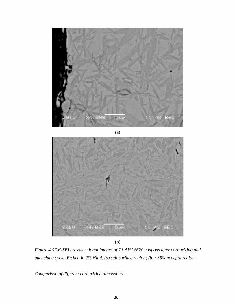
Microstructure, profiles of carbon concentration and microhardness of carburized layers
Cross-section microstructures of carburized surface layers produced at 900℃ are
shown in Figure 2-4. Microstructural analysis of the carburized test coupons revealed
carbides within the first 20μm carburized layer and a mixture of martensite and retained
austenite near the surface and a mixture of martensite and bainite in the core. From the
SEM-SEI pictures, about 5μm large martensite can be observed along with the carbides
at the subsurface area. In the 200-500μm depth area, which has the highest as-quench
hardness, very fine grain (~ 1μm) structure was detected.
While martensite is the desired phase in a carburized case, a large amount of retained
austenite, about 53% was also detected at 100μm depth, which resulted from direct oil
quenching at 843 o
C. In the maximum microhardness area, a mid-level of the retained
austenite (15-25%) was observed.
The carbon profile is measured using OES from 0-600μm depth, the very surface
contained high concentration carbon (>1.6 wt%) for all the conditions. It was expected,
using C3H8 as carbon source, graphite may generated and with extremely high carburizing
potential, cementite may exit at the surface. As shown in Figure 3, carbon content is
dropped significantly at 50μm depth to 0.9 wt% C and flattened into the core. By
integrated carbon concentration profile, the result of 0.03597g/cm2 weight gain matched
well with weight gain measured by microbalance. After 3 hours carburizing at 900 o
C,
AISI 8620 steel generated a 520 μ m case depth (case depth defined as carbon
concentration drops to 0.5 wt%).

35
Figure 2 T3(N2-2vol%C3H8carburized at 900 o
C for 3hrs, without plasma activation) oil
quenched from 843 o
C, not tempered AISI 8620 steel microstructure, microhardness and
retained austenite profile.
Figure 3 T1(N2-2vol%C3H8carburized at 900 o
C for 3hrs, with plasma activation) oil
quenched from 843 o
C, not tempered AISI 8620 steel microstructure, microhardness and
carbon profile.
36
(a)
(b)
Figure 4 SEM-SEI cross-sectional images of T1 AISI 8620 coupons after carburizing and
quenching cycle. Etched in 2% Nital. (a) sub-surface region; (b) ~350μm depth region.
Comparison of different carburizing atmosphere

37
The surface hardness HRC of the carburizing parts was measured and found to be
identical within a narrow range of measurement error, listed in Table 3. Cross-sectional
microhardness was plotted in Figure 5 and also displayed the similarity. As-quenched
AISI 8620 sample, started with 700-800 HV surface hardness, and reached the peak at
400μm, then with a sharp drop-off into the core area. The lower hardness at very surface
is due to high concentration retained austenite of more than 50%. And these profiles also
support carbon flux measurement that 2% C3H8 was sufficient to carburize test coupons
in the lab furnace. However, during industrial production, the parts per load have
enormous surface area compare to lab tests, and atmosphere residence time and
circulation also changed, so more than 2% C3H8 may be needed depend on different
variables.
Figure 5 Vickers microhardness profile for T1-3 carburized, oil quenched parts.
The microhardness after tempering at 180oC for 2 hours is presented in Figure 6.
From this figure, endogas, 4.5% methane with nitrogen atmosphere samples were
compared with T3 (2% propane, thermal run). The same process temperature and
schedule were followed for those tests, more details about methane and endogas runs are
listed in previous publication.[16] After tempering, the peak hardness at 400μm for as-

38
quenched condition was dropped from HV 900 to 740. Fine structure martensite turned
into tempered martensite, that resulted the hardness drop and less brittle structure was
formed. Compared with methane and endogas samples, the case depth and hardness are
all improved by using propane atmosphere, higher microhardness was obtained at 0-400
μ m working zone, and case depth was also increased about 100 μ m. The HC
atmosphere samples displayed a higher hardness level going deeper into the part with a
sharper drop-off in the core area than the endogas samples. This type of hardness profile
is desired, in the case of parts requiring an additional surface finishing by machining for
restoring dimensional accuracy.
Figure 6 Vickers microhardness profile for T3 ((N2-2vol%C3H8carburized at 900 o
C for
3hrs, without plasma activation)), 4.5%CH4 and endogas carburized, oil quenched and
tempered at 180oC for 2 hours and T3 non-tempered parts.
Process control
Numerous gas products are formed in the N2-C3H8 blend in the furnace. They include
CH4, C2H2, C2H4, C3H6, H2, and N2 and some by-product when HC gas reacts with
residual O2 in the furnace. [20] After preliminary experiments, it was observed that the
H2 concentration in the furnace effluent is the most sensitive real-time process measure.

39
Figure 7 Correlations between effluent gases and external zirconia probe readings
during carburizing tests involving N2-0.9%C3H8, N2-1%C3H8, and N2-2%C3H8
atmospheres at 930 o
C with plasma discharge activation and w/o it, using conventional,
thermal-only activation.

40
The changes of H2O, CO2, CO or CxHy are not as directly connected to steel surface
carburizing as that of H2, shown in Figure 7-8. It shows that other process indicators
change only within several hundred ppm range or may, like ZrO2-probe, become affected
by catalyzed carbon deposits. Through the correlation between carburizing ability and
hydrogen concentration can be changed by process variables. In most case, the H2 content
can still be used to determine the carburizing effectiveness, expect for some rare
situations. For example, heavy hydrocarbon impurities in the feed gas will result an
increase of carburizing ability, but appear as a decrease for hydrogen concentration in
furnace exhaust gas.
During the recipe development, modified shim stock methods (Appendix) can be
used, while H2 readings were recorded for future reference. Then in the following
production carburizing cycles, H2 sensor can be used to monitor the atmosphere solely,
and by adjusting inlet hydrocarbon concentration to match the pre-recorded H2
concentration, the carburizing atmosphere can be maintained as same as the previous run
to duplicate the results. Conventional ZrO2-probe can be used in the furnace conditioning
stage to monitor the O2 purge out rate and for safety control during carburizing.

41
Figure 8 Atmosphere concentration during T4 process. (a) CO, CO2 and H2 gases; (b)
Hydrocarbon gases
Industrial trial
Production scaled test was run at commercial heat treating facility. DIN16MnCr5
steel (equivalent to AISI 5115) parts were used in testing, with the technical target of
producing a 0.68 wt%C at the surface and 0.3 wt%C at 0.6 mm case under the surface in
a 90 minutes 930℃-boosting/930-860℃ diffusing cycle. Due to ingress of oxygen into IQ
furnace during carburizing operation, the N2-C3H8 atmosphere becomes ‘transitional’
between the conventional, non-equilibrium atmosphere characterizing vacuum furnace
carburizing and the endothermic gas-based, atmosphere. Although transitional N2-C3H8
atmospheres may, in principle, produce co-existing, intergranular carbides(IGC) and
oxides(IGO) during quenching, following carburizing, the actual size of those products is
negligible (less than 3-5 µm into surface, shown in Figure 9) because of the equilibrium
nature and very limited quantity of the oxygen-containing gases (i.e. CO, H2O, and CO2)
available for reaction.

42
(a)
(b)
Figure 9 Optical microstructure graph for coupons, shown (a) IGO and (b) cementite.

43
Conclusions
1. The steel carburizing process in 1-atm-pressure furnaces involving non-equilibrium
atmospheres containing propane gases was evaluated. Measurements of carbon mass
flux and calculations of carbon potential in gas phase have shown that the present
carburizing rates are comparable to those of low-pressure (vacuum) and endothermic
atmosphere carburizing systems.
2. Carburizing effects were compared for the AISI 8620 steel coupons processed with
the N2-C3H8, N2-CH4 mixture and the conventional endothermic atmosphere using
the same heat treatment schedule. The peak hardness and case depth for N2-C3H8
samples were improved compared with N2-CH4 sample. The microhardness profile
directly under metal surface was relatively flat, similar as by low-pressure
carburizing, and beneficial from the post-machining and fatigue strength standpoint.
3. Modified shim stock method and probe can be used for determining carbon flux from
atmosphere into metal combined with diffusion calculations for carbon concentration
profile at and under metal surface, described in Appendix. Carbon flux
measurements can be correlated with H2 concentration and, optionally, with other gas
sensors. Controlling hydrocarbon gas concentration during the subsequent,
production operations, where carbon flux measurements are no longer used as long
as the HC additions result in the same H2 during the recipe development run.
Acknowledgments
The authors would like to thank J.L. Green for laboratory support, and Air Products
for funding and the permission to publish this study.
References
[1] R.L. Davis et al, U.S. Patent 4,049,473
[2] An, X. et al, “A study of internal oxidation in carburized steels by glow discharge
optical emission spectroscopy and scanning electron microscopy”, Spectrochimica
Acta Part B 58 (2003) 689–698
[3] Chatterjee-Fisher, R., “Internal Oxidation During Carburizing and Heat Treating”,
Metallurgical Transactions Vol. 9A, November 1978, pp.1553-1560

44
[4] Asi, O., et al, “The relationship between case depth and bending fatigue strength of
gas carburized SAE 8620 steel”, Surface & Coatings Technology 201 (2007), pp.
5979–5987
[5] Kaspersma, J.H., and Shay, R.H., “Carburization and Gas Reactions of
Hydrocarbon-Nitrogen Mixtures at 850℃ and 925℃”, Metallurgical Transactions B,
Vol. 13B, June 1982, pp. 267-273.
[6] Estrin, B.M, et al, “Carburizing in a nitrogen-based mixture with additives of pure
methane”, Metallovedenie i Termicheskaya Obrabotka Metallov, No. 5, pp. 26-29,
May, 1984
[7] Connery, K. and Ho, S., “Optimization of Oxygen-free Heat Treating”, Proc. of the
24th ASM Heat Treating Society Conf., September 17-19, 2007, COBO Center,
Detroit, Michigan, USA
[8] Baldo et al, U.S. Patent 4,992,113
[9] Karabelchtchikova, O. and Sisson, R.D. Jr., "Calculation of Gas Carburizing
Kinetics from Carbon Concentration Profiles based on Direct Flux Integration",
Defect and Diffusion Forum Vol. 266,(2007), pp. 171 - 180.
[10] Karabelchtchikova, O. and Sisson, R.D. Jr., “Carbon diffusion in steels: A numerical
analysis based on direct integration of the flux”, Journal of Phase Equilibria and
Diffusion, Volume 27, Number 6,(2006) p598-604
[11] Herring, D.H., “Furnace atmosphere analysis by the shim stock method”, Industrial
Heating, Sept (2004)
[12] P. Beuret, U.S. Patent 5,064,620
[13] L.G. Chedid et al, U.S. Patent 7,068,054
[14] Winter, K.M., “A Guide to Better Atmosphere Carburizing Using Both Dynamic and
Equilibrium-Based Measurements”, Industrial Heating, Oct.(2008)
[15] Z. Zurecki et al, U.S. Patent 2008/0283153
[16] Zurecki, Z and Wang, X, “Atmosphere carburizing using electric discharge-activated
nitrogen-natural gas mixtures,” Heat Treating Conference and Exposition,
Indianapolis, Indiana, Oct 2009.
[17] Zurecki, Z., “Heat Treating Atmosphere Activation”, , Proc. of the 24th ASM Heat
Treating Society Conf., Detroit, Michigan, Sept. 2007.

45
[18] Linde Gas, Special Edition, “Furnace Atmospheres No. 1, Gas Carburizing and
Carbonitriding”, url:
https://b2.boc.com/catweb/CATweb.nsf/noteid/EC84EBA1ADCB86EC802572C100
4B3977/$file/SpEd_Carburizing_and_Carbonitriding.pdf, last accessed: March 24,
2009
[19] Altena, H., and Schrank, F., "Low Pressure Carburizing with High Pressure Gas
Quenching", Gear Technology, March/April 2004, pp.27-32
[20] R.U. Khan et al, Pyrolysis of propane under vacuum carburizing conditions: An
experimental and modeling study, J. Anal. Appl. Pyrolysis, 81 (2008) 148–156
Appendix
The following section describes a procedure for estimating carbon flux into steel
during carburizing operations in non-equilibrium atmospheres. Modified shim stock
methods can be used to determine the carbon flux into parts in-situ. Tube shape samples
were used and only the OD was exposed to the carburizing atmosphere. The wall
thickness, W, and carburizing exposure time, t, are selected in such a way that the
unexposed ID side is not yet carburized by the flux of carbon atoms flowing from the
exposed side. Weight gain due to carburizing was measured by using conventional
microbalance.
The procedure requires several coupons insertion into the furnace, for different time
periods, such as t1, t2 and t3. The formulas for calculating the fluxes from the three weight
gain measurements are listed in Table 4, where m1, m2, and m3 are the gains at the end of
each exposure time, t’ times are the times assigned for specific weight gains, and J are the
averaged flux values associated with the t’ times.
The following assumptions were made to simplify the procedure and calculation. In a
short period of time, carbon flux and time have a liner relationship; during the whole
carburizing time, process temperature and atmosphere were maintained the same.

46
Table 4: Calculation of average fluxes for exposure times
Data used Time Carbon flux
Figure 10 shows the typical weight gains registered by 3 metal coupons exposed to
the carburizing atmosphere for t1, t2 and t3. The line connecting the weight gain
datapoints measured reflects the decreasing rate in view of increasing carbon
1 exposure, i.e.
m1, is the average gain associated with the middle of the exposure time, i.e. t1’=1/2t1.
The same operation can be repeated for the longer exposure times, but it should be noted
that the longer the exposure time is, the larger error results from associating the average
gain with the half of the exposure time used.
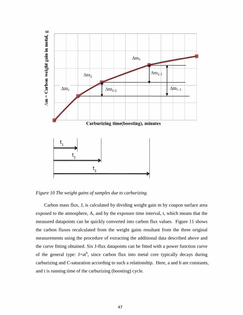
47
Figure 10 The weight gains of samples due to carburizing.
Carbon mass flux, J, is calculated by dividing weight gain m by coupon surface area
exposed to the atmosphere, A, and by the exposure time interval, t, which means that the
measured datapoints can be quickly converted into carbon flux values. Figure 11 shows
the carbon fluxes recalculated from the weight gains resultant from the three original
measurements using the procedure of extracting the additional data described above and
the curve fitting obtained. Six J-flux datapoints can be fitted with a power function curve
of the general type: J=atb, since carbon flux into metal core typically decays during
carburizing and C-saturation according to such a relationship. Here, a and b are constants,
and t is running time of the carburizing (boosting) cycle.

48
Figure 11 Estimation of average carbon flux using modified steel coupon probes
The fitted curve represents time dependant flux value and, in the next step, can be
extrapolated up to the maximum carburizing time of interest, e.g. to 60 minutes, if 60
minutes was the original boosting time intended for the analyzed operation. Thus, in the
next step, the average flux for the 60 minute boosting can be calculated using the same,
offline computer spreadsheet by averaging the value integrated under this fitted curve.
An offline diffusion software package, e.g. “CarbTool”, by Worcester Polytechnic
Institute, is needed in the final step to evaluate carbon profile generated by the
carburizing process. Carbon profile can be predicted by entering the temperature, time,
carbon flux and other parameters. By completing this procedure, the surface carbon and
carbon depth of the products can be estimated and evaluated.

49
Paper 2: Nitrding of carbon, alloy and stainless steels by diluted ammonia
(to be submitted to International Heat Treatment and Surface Engineering)
Abstract
Atmosphere nitriding with diluted ammonia containing small additions of
hydrocarbon gases can offer cost and energy saving alternatives to the conventional
operations. This study presents results of nitriding AISI 1008, 4340, nitralloy 135 and
stainless steel 301 using a modified, 4-hr long, atmospheric-pressure treatment method
involving an electric arc-activated N2—25vol%NH3 blend with a carbon-sourcing gas
addition not exceeding 1.25vol%. Laser gas analyzer was used to monitor residual
concentrations of H2, NH3 and CH4 inside the furnace. Experimental procedures included
laser analysis of furnace atmospheres, SEM-EDS, XRD, OM and Leco combustion
element tests, microstructural and compositional characterization of product layers, and
evaluation of nitriding potential (KN) and activity (aN). A 15µm white layer with a 150-
200µm case depth was generated for carbon and alloy steel after 4 hours treatment. Rapid
growth of hard (HK=~1100), nanostructured, nitride rather than carbide layers was
observed on 301 stainless steel sample at 565oC with growth rates exceeding 20 µm/hr.
Overall, nitriding with nitrogen diluted ammonia gas provides an alternative to an long-hour
pure ammonia nitriding with more efficient energy utilization.
1. Introduction
The conventional gas nitriding in the U. S. was often performed by holding the
steel at a suitable temperature in the ferrite phase region in contact with a nitrogen
content gas, usually ammonia.1-3
After the nitriding, high surface hardness, increased
wear resistance, improved fatigue life and better corrosion resistance can be expected.
Also because of the absence of a quenching requirement and the low process
temperatures, nitriding of steels produces less distortion and deformation than carburizing
and quenching. 3 Unfortunately, the nitriding process can be difficult to control. Nitriding
reactions are strongly influenced by the surface cleanliness, oil surface or certain cutting
fluid residue can block the nitrogen diffusion.1 High chromium steel may need surface
activation, such as plasma sputtering as chemical activation, to be successfully nitrided.
50
Ammonia which is toxic and flammable is needed as the process gas. The shipment,
storage and proper disposal of the large amount of ammonia will also increase the costs.
And, due to the nature of diffusion, at around 500°C, the rate of nitrogen penetration and
diffusion is very slow, so extremely long process time is needed for creating a usable
hardened case, normally 24-48hr was needed to produce a 200µm case. Considering all
the aspects, the cost of nitriding compared to other surface treatment is still low, but
roughly 50% more expensive than carburizing. The approximate cost for low-alloyed
steel nitriding is from $2/lb for 0.005” case (~ 5hrs, no evaluation coupons) to $10+/lb
for 0.025” case (~25hrs, acceptance coupons included).2
As we know, the nitriding process often takes an extremely long time.1,3
So in
order to accelerate the nitriding process, numerous investigations have been conducted.4-9
Cathode sputtering with voltage; 700–1350 V, current density; 1–4 A/cm2, for 10 min
will activate the steel surface and shorten the nitride nucleation time than without
sputtering and product a larger nitriding case during same process time.4, 5
It also has been
noticed, the roughness of parts surface will influence the nitriding results, mirror polished
samples (Ra = 0.05) exhibited high hardness and case depth after plasma nitriding
compared to the rough polished (Ra = 0.075), machined (Ra = 0.47) and ground (Ra = 1.02)
samples, due to the presence of ferrite on the surface which facilitated diffusion of
nitrogen into the sample during plasma nitriding.6
Using an activator (1% aqueous HCl)
in pretreatment to create a uniform nitrided layer has also been investigated.7
Some
research has been done in the effect of residual stress in nitriding, samples with low
values of residual stress give higher penetration depths of nitrogen, compared to samples
with high levels of residual stresses.8
It was also claimed 10.5 +/- 0.5min pre-oxidation in
water steam increased 30%-50% nitriding rates.9
In patent US 2007/0204934 A1, 10
it claimed with some additional active
hydrocarbon gas in the ammonia, HCN can formed and it can improve the uniformity of
nitriding treatment and the nitrogen penetrating. This treatment will shorten the nitriding
time to archive the same case depth. El-Rahman11
also investigated the effects of high
percentage C2H2 used in r.f. plasma carbonitriding for austenitic stainless steel. CH4 is
51
also used in plasma immersion ion implantation X5CrNi189 steel (AISI 304 stainless
steel).12
The results show both improvement in larger case depth and higher hardness.
In this research, hydrocarbon gas addition to the nitriding atmosphere and electric
arc discharge activation of the gas on the kinetics of the nitriding process was
investigated. Methane is used as the activated gas. Prior to and during the nitriding,
hydrocarbon gases were reacted with metal surface and removed oxidation layers, which
can accelerate nitrogen absorption. Gas stream-activating, cold-plasma injectors
developed at Air Products is also used in these experiments. 13,14
2. Experimental procedure Atmosphere nitriding experiments were conducted on a semi-production scale,
electrically heated box furnace, ATS 3350. Gas analyses were performed by laser gas
analyzer (manufactured by ARI, model LGA-4ENAPBT) for CO, CO2, H2, CxHy and
NH3. The AISI 1008 0.203 mm (0.008”) shim, 301 stainless steel 0.203 mm (0.008”)
shim, 4340 disk and nitralloy 135 disk were used in the tests. The AISI 1008 and 301
stainless steel shim stock used in this study were cut into 76 mm by 102 mm (3’ by 4’)
square and degreased by acetone prior to the nitriding process. Before nitriding, the
cylindrical AISI 4340 and nitralloy 135 steel bars were quenched from 900oC and
tempered for 2 hours at 580oC, then machined into Φ25mm*7mm (Φ1”*1/4”) discs.
Table 1 Element composition of the alloys tested by OES (wt%)
C Mn Cu Cr Mo Ni Al Si Fe
1008 0.080 0.37 - - - - - - Bal
4340 0.391 0.67 0.18 0.76 0.192 1.42 0.036 0.208 Bal
#135 0.377 0.367 0.123 1.10 0.266 0.064 0.98 0.164 Bal
301ss - 0.71 0.34 16.54 0.24 7.23 - - Bal
Nitriding of these specimens was performed according to the conditions. Several
process temperatures were picked for group A test. The atmosphere condition is
maintained the same with 12% NH3 diluted by nitrogen gas, and 4 hours treatment at
500-565oC range. In group B test (table 2), T1b were non-activation, thermal nitirding

52
test. T2b, 3b were performed under AC-plasma activated gas atmosphere. The cold
plasma, stream-activating injector was used, equipment details were described elsewhere.
The atmosphere used in the tests were NH3 (25 vol%) in N2-stream with small amount of
CH4 addition, a total flowrate of 100 scfh, 1.5 volume change per minute in the box
furnace. The nitrogen gas used to balance total gas stream has 99.995% purity. Each
nitriding cycle involved 30min long heating period from room to treatment temperature,
4 hour nitriding step at 565oC and slow cooling in the furnace.
Table 2 Nitriding of carbon, alloy and stainless steels test
T1a T2a T3a T1b T2b T3b
Temp.(oC) 500 525 565 565 565 565
Plasma usage None, thermal None,
thermal
AC-
2transfs
AC-
2transfs
‘CH4 turned
on’ time None
Heatup+first
hour only All the time Heatup only
‘Plasma
power on’
time
None None,
thermal All the time Heatup only
Inlet NH3% 11.9% 12.1% 11.9% 24.7% 24.85% 24.79%
CH4% - 1.23% 1.24% 1.25%
The specimens were weighted before and after the nitriding cycle with a
conventional microbalance, accuracy of 0.1mg. Microhardness and SEM test were
performed on coupons afterwards. Knoop hardness on the cross-sections, 25g for 10s,
was taken for the coupons and shims on Shimadzu HMV-2000 Micro Hardness tester.
Metallographic cross-sections of the coupons were etched with 2% Nital or oxalic acid
prior to OM and SEM examination. LECO combustion test for through average element
concentration was also performed afterwards for selected coupons.

53
3. Result and discussion After 4 hours treatment, the average nitrogen weight percentage in the 1008 steel
shim increased from 0 to 0.6-1.2 wt% with no oxidation, as shown in Table 3. When
temperature increased from 500 to 565
oC, the nitrogen pickup almost doubled as seen in
Figure 1. So within the range of nitriding temperature which is below the eutectoid
temperature (590°C for pure iron), higher process temperature is preferred to shorten the
time and reduce cost. It also has been noticed that the nitriding potential and activity of N
in atmosphere didn’t have the clear relationship in nitrogen pick for diluted ammonia
atmosphere.
Table 3 Diluted NH3 nitriding test results at different temperature
T1a T2a T3a
Temp.(oC) 500 525 565
Inlet NH3% 11.9% 12.1% 11.9%
Residual NH3% 11.4% 10.6% 7.3%
NH3 dissociation rate 5% 12% 39%
Wt. gain per unit area (mg/cm2) 0.497 0.658 0.922
N% in metal (by leco) 0.67% 0.94% 1.24%
O% in metal (by leco) 0.019% 0.024% 0.019%
K (lnK=14.05-6594/T) 250 326 484
KN, Nitriding potential 165.9 38.9 5.9
aN, activity of N in atm. 41410 12691 2866

54
Figure 1 Nitrogen weight gain as function of nitriding temperature.
During 565oC test, AISI 4340 and nitralloy 135 steel showed similar results under
the test conditions. 1008 shim developed a 15-20µm 500-600 HK hardness “white”
nitrided layer. 4340 steel coupon has surface hardness >700 HK; nitralloy 135 coupon
has surface hardness ~1000 HK.
Table 4 Atmosphere concentration and nitriding potential for test B series
T1b T2b T3b
Inlet NH3% 24.7% 24.85% 24.79%
CH4% 1.23% 1.24% 1.25%
Residual
(with HC)
NH3% 21% 18.20% -
H2% 3% 5.88% -
CH4% 1% 1.09% -
KN (with HC) 40.4 12.8 -
Residual
(w/o HC)
NH3% 19% - 18.80%
H2% 4% - 5.84%
KN (w/o HC) 23.8 - 13.3

55
The nitriding potential has also been calculated and plotted in Figure 2 along with
the nitrided layer thickness for all alloy steels. Similar nitrides layers developed under
different nitriding potential, the relationship of nitriding potential and case depth is not
clear for diluted ammonia atmosphere.
Figure 2 Nitrided layer thickness for different alloy (565oC, 25%NH3, 4hrs)
Figure 3 Nitralloy 135 and AISI 4340 coupon microhardness profile (565oC, 25%NH3,
4hrs)

56
Figure 4 Typical microstrucutre of nitrided layers produced on AISI 4340 and Nitralloy
135 by gas nitriding at 565oC for 4hr. The specimens were etched with 2% Nital.
Microstructural examinations revealed that a nitrogen-enriched compound layer
can be produced on the investigated alloys. Figure 4 shows typical morphology of the
nitrided layers produced on AISI 4340 and Nitralloy 135. There is a compound layer
formed on the surface for both steels. AISI 4340 steel has a ~15µm compound layer and
~200 µm diffusion layer. Nitralloy 135 developed a ~15µm compound layer and ~150µm
diffusion layer.
301 stainless shim developed a 80micro “dark” nitrided layer which is 4 times
larger than alloy steel with the hardness of 1000 ~1100 HK. With hydrocarbon gas
injected for whole process time or light power plasma activation used, T2b-T3b have
identical layer thickness, more than 20% larger than T1b(no plasma and only partially
process time with HC gas addition) for all samples.

57
Figure 5 The ingrowth & outgrowth of nitrided layers (565oC, 25%NH3, 4hrs)
Secondary electron images (SEM-SEI) of cross-sections of the nitrided shim, and
the corresponding, elemental maps of Mn, Cr, Ni and Fe were acquired using energy-
dispersive X-ray spectroscopy (EDS) probe. 7-8 micros outgrowth is observed for all the
301 ss samples, which has the same thickness of the white narrow outer layer observed
under SEM, shown in Figure 6. In this layer, higher Ni, Fe% and lower Cr, Mn% is
observed by EDS, compared to dark wide inner layer. Cr-Mn rich secord Layer
catalyzing and nucleating the growth of “dark, wide, inner layer” below.

58
Figure 6 Microstrucutre of nitrided layers produced on AISI 301stainless steel by gas
nitriding at 565oC for 4hr. The specimens were etched with 2% Nital or oxalic acid.

59
Figure 7 SEM-SEI-EDS cross-sectional images of subsurface regions of the nitrided 301
stainless steel shim
Assuming the concentration of N, C and O in the steel are constant in compound
layers, using known layer thickness and shim thickness and through element

60
concentration by Leco test, compound layer N wt% can be estimated. About 4.5 wt%
nitrogen in the 301 ss shim nitrides layer and for 1008 shim, 8.2% nitrogen was expected
at the white layer, shown in Figure 8.
Figure 8 The estimation of N, C and O wt% in nitrided layer
X-ray diffraction was used to identify the nitrides phase near the surface. The
sample T5b was scanned on the MPD from 30-85o using X’Celerator optics, Cu-Kα
radiation, a 0.03o step size and 800 sec count time. The layer was found to consist of
several nitride phases with the best match consisting of a mixture of cubic Fe4N, cubic (γ’
phase) CrN, and hexagonal Fe3N1.1 (ε phase). Other nitrides that may be present include
Cr2N0.9, Ni4N, and Fe although peak positions of these phases do not match the observed
peak positions as well as the previously mentioned phases. Although the nitrocarburizing
atmosphere contains both NH3 and CH4, at low temperature, only Cr and Fe nitrides are
formed, no carbides can be detected by XRD.

61
Figure 9 X-ray diffraction patterns for 565oC nitrided AISI 301 stainless steel
During the initial nitriding, the nitrides nucleated on the steel surface at individual
actived spot and formed protruding submicroscopic crystallites which growed outside
and inside the metal bulk. A disconnected nitrided layer was observed, from the cross
section and top surface, nano size particles formed during initial nitridng stage, shown in
Figure 10.
Figure 10 Top view of nitrided layers produced on AISI 301stainless steel by gas
nitriding at 565oC.

62
Figure 11 X-ray diffraction patterns for 565oC nitrided AISI 301 stainless steel
The rapid nitriding of 301SS shim have been triggered by the recrystallization of
this cold-rolled metal. No clear correlation was observed between nitriding potential and
nitride layer thickness. However, the presence of CH4 in the atmosphere increases
nitriding potential. For the conditions tested, i.e. introduction of N2, NH3 and CH4
through arc discharge, high-power arc activation always reduces residual NH3 in
atmosphere and, thus, reduces nitriding potential. Nitriding progresses in the inward
direction with respect to the original interface with a small only outgrowth amounting to
about 10% of the total layer thickness. No clear arc-activation effect on layer thickness or
microhardness on any of the materials tested.
4. Conclusion In this experimental study on the behavior of carbon steel, alloy steel and stainless
steel under same nitriding condition with diluted ammonia, the following key
observations are made:

63
15µm white layer with 150-200µm case depth was generated for carbon and alloy
steel after 4 hours treatment. It’s faster than conventional nitriding rate.
80µm nitrids layer with high hardness was formed in 4 hours process time. In this
layer, higher Ni, Fe% and lower Cr, Mn% is observed by EDS. The rapid
nitriding of 301 SS observed could have been triggered by the concurrent
recrystallization of this cold-rolled metal.
No clear correlation was observed between nitriding potential and nitride layer
thickness. However, the presence of CH4 in the atmosphere increases nitriding
potential. Although the atmosphere contains both NH3 and CH4, at low
temperature, only nitrides are formed.
In future, more test conditions should be repeated, including surface preoxidation
during heating, w/o CH4 activation and with activation using other, less stable
hydrocarbons, e.g. C3H8, at various concentrations.
5. References 1. Practical Nitriding and Ferritic Nitrocarburizing, ASM International, 2003
2. J.R. Davis, Surface Engineering for Corrosion and Wear Resistance, ASM
International, 2001
3. G.E. Totten, M.A.H. Howes, Steel heat treatment handbook, p722-730, 1997
4. J. Baranowska, K. Szczeci ski and M. Wysiecki, Cathode sputtering as a pre-
treatment for gas nitriding, Vacuum, Vol. 63, Issue 4, 2001
5. J. Baranowska and M. Wysiecki, Influence of surface pretreatment on case
formation during gaseous nitriding, Surface and Coatings Technology, Vol. 125,
Issues 1-3, 2000
6. G.P. Singha, and etc., Effect of surface roughness on the properties of the layer
formed on AISI 304 stainless steel after plasma nitriding, Surface and Coatings
Technology, Vol. 200, Issues 20-21, 2006
7. W.D. Jentzsch and S. Bohme, Investigations on Nitride Layer Formation at the
Iron Surface during Gas Nitriding, Crystal Research and Technology, Vol. 14,
Issue 5, 1978

64
8. T.K. Hirsch, A.S. Rocha, F.D. Ramos, and T.R. Strohaecker, Residual Stress-
Affected Diffusion during Plasma Nitriding of Tool Steels, Metallurgical and
Materials Transactions A, Vol. 35, No. 11, 2004
9. R. Yang and T. Hu, Study of the Gas Nitriding Catalyzed by Pre-oxidation, Hot
Working Technology, Vol. 4, 1996
10. P.N. Kogyo K.K., Method for activating surface of metal member, Patent
2007/0204934 A1, 2007
11. A.M. Abd El-Rahman and etc., Effect of N2 to C2H2 ratio on r.f. plasma surface
treatment of austenitic stainless steel, Surface and coatings technology, vol.183,
p268-274, 2004
12. C. Blawert and etc.,Characterisation of duplex layer structures produced by
simultaneous implantation of nitrogen and carbon into austenitic stainless steel
X5CrNi189, Surface and coatings technology, vol.128, p219-225, 2000
13. Z. Zurecki, Heat Treating Atmosphere Activation, Proc. of the 24th ASM Heat
Treating Society Conf., September 17-19, 2007
14. A. Fridman, Plasma Chemistry, Cambridge University Press, 2008

65
Paper 3: Development of Low-Cost, Rapid Case Hardening Treatments for
Austenitic Stainless Steels (to be published in Heat Treating Conference and
Exposition, 2011)
Abstract
Austenitic stainless steels are critical in the modern economies with applications
ranging from food processing and cryogenic machinery to medical implants and
aerospace instrumentation. Tough, resistant to low-temperature embrittlement and many
forms of corrosion, these steels are, nevertheless, prone to scratching and galling in
service. Case hardening was found to be effective when combined with corrosive surface
treatments or in low-pressure, direct plasma-ion discharges, but inhibited in simple
atmospheric-pressure furnaces. This paper presents preliminary evaluation of new, rapid
(3-4 hrs) nitriding and carbonitriding treatments at low- (500-565℃) and high- (1100℃)
temperature ranges involving injection of high-voltage, electric arc-activated, N2-based,
NH3 and hydrocarbon gas mixes to the conventional box furnace. Reported data includes
characterization of stainless steel product layers using SEM-EDS, XRD, OM, Leco
elemental analysis, and microhardness profiling, as well as laser gas analysis of the
residual furnace atmosphere.
Introduction
Stainless steel is a widely used material where corrosion resistance is needed. In
2010, the production of stainless steel is 30.7 million tons worldwide, which is more than
carbon steel. And among that, 57.7% is 300 series austenitic stainless steels.[1] Austenitic
stainless steels are highly valued for their corrosion, oxidation and thermal resistance,
toughness and ductility, even at cryogenic temperatures. These steels contain high levels
of chromium (Cr), as well as nickel (Ni) and/or manganese (Mn) that help stabilize their
austenitic structure.[2]
Many processes have been developed to improve the stainless steel hardness and
wear resistance.[3-14] Three, largely proprietary processes are best known in the US at

66
present: ion-nitriding and carburizing in partial vacuum, plasma furnaces[3-5]; low-
temperature (350-550℃) nitriding involving metal surface pre-etching using corrosive
and toxic gases[6-11], and solution nitriding at high temperatures assuring the presence
of austenitic phase during diffusion treatment (1050-1200℃)[12-14].
It is desired to treat and harden the steel surface using nitriding, an inexpensive,
thermochemical-diffusional process, well proven in the field of low-alloy and carbon
steels. But unfortunately, the passive oxide films forming on metal surface act as dense
diffusion barriers and prevent the conventional nitriding for stainless steel. Many
methods have been developed recently to overcome the problem of passive oxide films.
Thus, the metal surface could be dry-etched at elevated temperatures in halide gases such
as hydrochloric acid (HCl) [15] or nitrogen trifluoride (NF3) [16], or low-pressure
(vacuum furnace) nitriding using plasma ion glow discharges [3-5]. The method requires
a prolonged, multi-hour processing time, and necessitates significant capital, safety
equipment, and maintenance expenditures. Due to the complex surface activation steps
before the process or low pressure which normally used, the hardening step for stainless
steel is often expensive.
Second problem is chromium can react with nitrogen and carbon and form nitrides
which will cause loss of corrosion resistance. In 1985, Zhang and Bell observed that at
temperatures below 450oC, large quantities of nitrogen or carbon can be dissolved in the
stainless steel to form expanded austenite phase (S-phase) which can improve wear
resistant and corrosion resistance of steel simultaneously.[6] But this technique often
requires plasma/implantation based techniques, which limited production capacity.[17]
Expanded austenite is metastable and tends to form chromium nitrides. The high content
of N is obtained, because of the relatively strong affinity of Cr atoms for N atoms, to
short range ordering of Cr and N. Due to the low mobility of Cr atoms as compared to N
atoms at low treatment temperatures, chromium nitrides do not precipitate until after long
exposure times. And high hardness (up to 1700 HV) can be obtained by nitriding
austenitic stainless steel.[9] The high concentration of interstitial atom in solid-solution
and the occurrence of an enhanced stacking fault density may contribute to strengthen the
austenite stainless steel. But the production rate of S-layer is extremely slow due to the

67
low process temperature. Normally 10-20µm S-layer is expected after 22 hours treatment,
with the hardness above 1000HV.[8]
To making austenitic stainless steels case hardening process more affordable,
modified conventional, atmosphere pressure process was investigated in this research.
Activation of nitrogen or nitrogen-ammonia atmospheres was used, depending on the
treatment type and temperature desired, hydrocarbon(HC) gas additions [18] and/or
electric discharge (cold plasma) injection.[19-20] With small percentage active
hydrocarbon gas in the ammonia, HCN can formed and it can improve the evenness of
nitriding treatment and the nitrogen penetrating. El-Rahman [21] also investigated the
effects of high percentage C2H2 used in r.f. plasma carbonitriding for austenitic stainless
steel. CH4 is also used in plasma immersion ion implantation X5CrNi189 steel (AISI 304
stainless steel).[22] The results show both improvement in element concentration, larger
case depth and higher hardness.
Overall, case hardening stainless steel is difficult and expensive due to the native
passive layer which blocks the nitrogen and carbon penetration. It is desired to find an
inexpensive, efficient way to treat and harden the stainless steel using minimum modified
atmospheric process which is well proven in the field of low-alloy and carbon steels. This
study is mostly focused on exploring the feasibility of case hardening stainless steels, the
objectives of the paper are to: (1) develop the conventional, atmospheric-pressure, low-
cost surface hardening treatments for the case hardening of stainless steel at different
temperature range; (2) explore the possibility of activation of atmosphere and metal
surface to accelerate processing time and save energy and time; (3) generate S-layer in
short time period with plasma or/and hydrocarbon activation atmosphere.
Experimental procedure
Atmosphere nitriding experiments were conducted on a semi-production scale,
electrically heated box furnace, ATS 3350. Gas analyses were performed by laser gas
analyzer (manufactured by ARI, model LGA-4ENAPBT) for CO, CO2, H2, HC and NH3.
The 203µm thick AISI 301 stainless steel shim stock and 762µm thick AISI 304 stainless
steel plate used in this study were cut into 76 mm by 102 mm (3’ by 4’) square and
degreased by acetone prior to the nitriding process. The cylindrical AISI 304 stainless

68
steel bars were machined into Φ25mm*7mm (Φ1”*1/4”) discs. Element concentration
was test by X-ray fluorescence (XRF), listed in Table 1.
Table 1 Composition of the alloys tested by XRF (wt%)
Ni Mn Cr Mo Cu Fe
301 ss shim 7.23 0.71 16.54 0.24 0.34 Bal
304 ss plate 8.24 1.91 18.40 0.34 0.374 Bal
304 ss disk 8.37 1.57 18.16 0.39 0.30 Bal
Table 2 Low temperature nitriding test for stainless steel
T1 T2 T3 T4
Material 762µm 304ss plate 203µm 301ss shim
Nitriding temp. (oC) 500 500 565 565
Time(hr) 4
NH3% - inlet 25
CH4% - inlet 2 2 1.25 1.25
‘CH4 on’ time Non-stop Heatup
only
Activation used None AC 80% AC 20% AC 20%
‘Activation on’ time - Non-stop Non-
stop
Heatup
only
NH3 activation N N Y Y
The cold AC plasma, stream-activating injector was used in the test, equipment
details were described elsewhere.[18-19] For low temperature test series, the atmosphere
used were NH3 (25 vol%) in N2-stream with small amount of CH4 (<2 vol%) addition, a
total flowrate of 100 scfh, 1.5 volume change per minute in the box furnace. The nitrogen
gas used to balance total gas stream has 99.995% purity. Each nitriding cycle involved
30min long heating period from room to treatment temperature, 4 hours nitriding step at
500 or 565℃ and slow cooling in the furnace, listed in Table 2. For high temperature test

69
series, process temperature was maintained at 1100℃, and N2 process gas was used with
small addition of other active gas of total 100scfh flowrate, details listed in Table 3. Each
cycle involved 60min long heating period from room to treatment temperature, 4 hours
holding time at 1100℃ and quenching in water.
Table 3 High temperature test for stainless steel
T5 T6 T7 T8
Material 304 ss disk
Treatment temp.(oC) 1100
Time(hr) 4
Atmosphere N2 1.5%CH4+N2
Activation used None AC
80% None
AC
80%
‘Activation on’ time Non-stop
The specimens were weighted before and after the nitriding cycle with a conventional
microbalance, accuracy of 0.1mg. Microhardness and SEM test were performed on
coupons afterwards. Knoop hardness on the cross-sections with 25g for 10s, was taken
for the coupons and shims on Shimadzu HMV-2000 Micro Hardness tester.
Metallographic cross-sections of the coupons were etched with 2% Nital, oxalic acid or
50 vol% HCl + 25 vol% HNO3 + 25 vol%H2O solution prior to optical microstructural
and SEM examination. LECO combustion test for through average element concentration
was also performed on shim stock afterwards for selected test conditions. X-ray
diffraction (XRD) was used to identify the nitrides phase near the surface. The sample
was scanned on the MPD from 30-85o using X’Celerator optics, Cu-Kα radiation, a 0.03
o
step size and 800 sec count time.

70
Result and discussion 1. initial stage of nitrides growing
At initial stage of 565oC low temperature nitriding, microscopic crystallites were
observed growing on the surface of stainless steel coupons after the first few minutes of
nitriding treatment, shown in Figure 1(a). The graph indicates fresh metal surface and the
first crystallites on the surface. As the treatment time progresses, the entire metal surface
becomes covered with the crystallites and connected, shown in Figure 1(b).
Figure 1 Top view of nitrided layers produced on AISI 301stainless steel by gas nitriding
at 565oC.
Figure 2 shows 2% Nital acid etched cross sections of the metal surfaces covered
by the crystallites under an increasing magnification, identified in Figure 1(a). The
micrographs suggest that the nitriding process starts with a few selected nucleation sites
rather than uniformly, and these surface nuclei, once formed, grow into the parent metal,
joining together at a later stage. The initial absence of a planar growth front is interpreted
by applicants as the consequence of the N2-NH3-CH4 atmosphere used and its site-
activating effect on metal surface. It’s also observed that the recrystallization was
initialed by nitrogen diffused into metal core, shown in figure 2(b) and (c).
(a) (b)

71
Figure 2 Cross-section of nitrides crystallites generated at 565oC on AISI 301 stainless
steel, etched by Nital acid.
2. Nitrides layers
After 4 hours treatment at 565oC (T3-4), a continuous nitrides layer formed in AISI
301 stainless steel shim. 301 stainless shim developed an 80micro “dark” nitrided layer
which is 4 times larger than alloy steel (shown in Figure 3) with the hardness of 1000
~1100 HK (shown in figure 4). With hydrocarbon gas injected for whole process time or
light power plasma activation used, T3-T4 have identical layer thickness for all samples.
(a)
(b) (c)
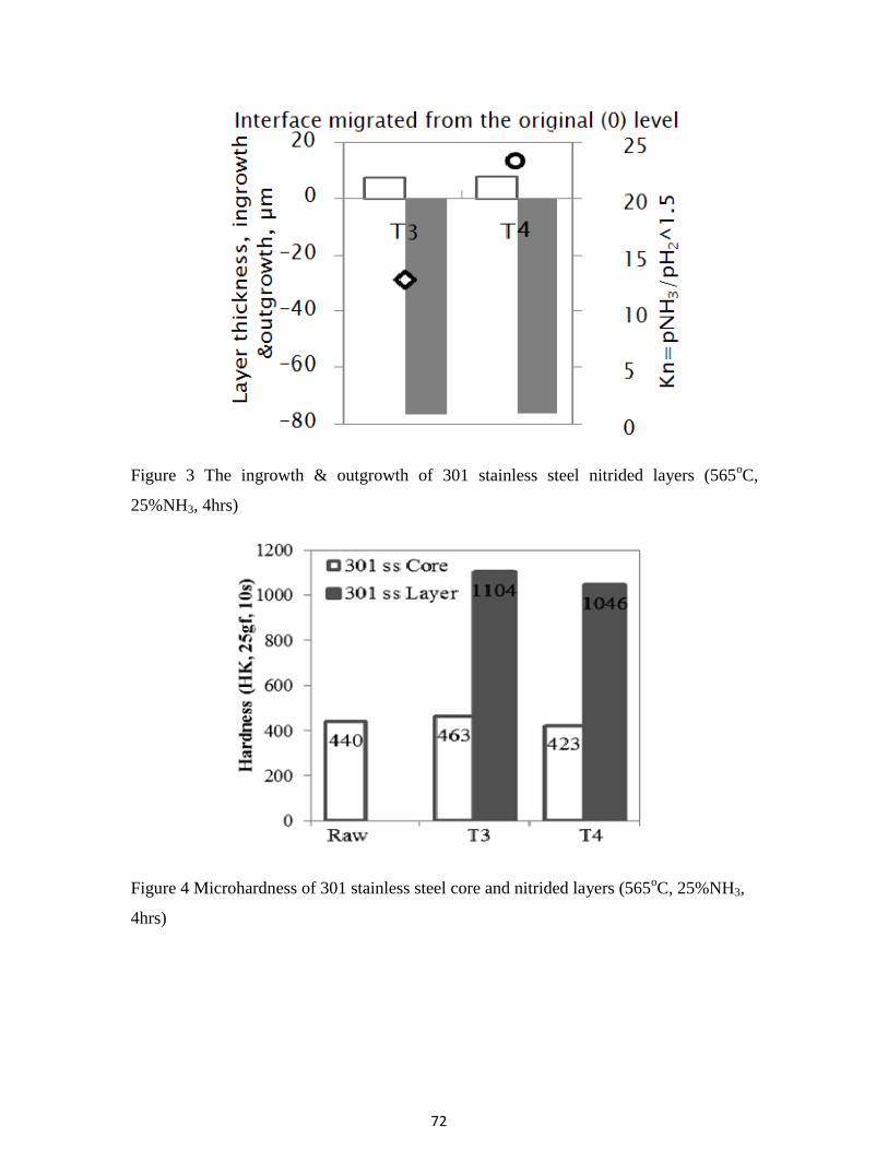
72
Figure 3 The ingrowth & outgrowth of 301 stainless steel nitrided layers (565oC,
25%NH3, 4hrs)
Figure 4 Microhardness of 301 stainless steel core and nitrided layers (565oC, 25%NH3,
4hrs)

73
Figure 5 SEM-SEI-EDS cross-sectional images of subsurface regions of the nitrided 301
stainless steel shim.
SEI-T4

74
Figure 6 The estimated distribution of interstitial of N, C and O wt% in nitrided layer,
plotted per elemental Leco analysis of treated and untreated shims (up) and SEM
micrograph of cross section of the 301 SS shim after the nitriding treatment, etched by
oxalic acid (bottom).
Secondary electron images (SEM-SEI) of cross-sections of the nitrided shim (T4),
and the corresponding, elemental maps of Mn, Cr, Ni and Fe were acquired using energy-

75
dispersive X-ray spectroscopy (EDS) probe. 7-8 micros outgrowth is observed for all the
301 ss samples, which has the same thickness of the White narrow outer layer observed
under SEM. In this layer, higher Ni, Fe% and lower Cr, Mn% is observed by EDS,
compared to dark wide inner layer. Cr-Mn rich layer catalyzing and nucleating the
growth of “dark, wide, inner layer” below. The dark layers (shown in figure 5) growing
from the surface into the core of the specimen indicate the depth of nitriding; the white
strip in the core is the unaffected parent metal. The difference in color response may be
the consequence of different etching rates –the nitrided stainless steel is less resistant to
etching than the parent stainless steel. The layers growing into 301 stainless steel are over
4-times thicker than the layers growing into low carbon steel. This finding is unexpected
and suggests that the N2-NH3-CH4 atmosphere described herein is uniquely suited for
nitriding of highly-alloyed metals which tend to resist the conventional nitriding methods
due to the presence of Cr-rich, passive oxide films.
The same nitrided 301 stainless steel specimen was etched with oxalic acid in
order to reveal grains in the nitrided layers and in the unaffected, parent metal core, here
visible as a narrow strip in the center of the microscopic image, shown in figure 6.
Elemental chemical analyses were carried out on raw and nitride shims for nitrogen (N),
carbon (C) and oxygen (O) using a Leco combustion gas extraction analyzer. The results
are plotted directly above the image of the crosssection. It is apparent that the nitrided
layers contain about 4.5 wt% of nitrogen while the N-content in the parent metal is zero.
The O-level in the nitrided layers is very low, about 0.01 wt%, not much more than in the
parent metal. Finally, the C-level in the nitride layers is below 0.12 wt%, less than in the
parent metal. This confirms that the CH4- containing atmosphere of this invention does
not carburize the metal treated but, only, accelerates the nitriding. Comparison of the
nitride layer and parent metal hardness suggests that the presence of the CH4 addition
throughout the entire, 4-hour long nitriding cycle is important for metal hardening, even
though there is no carburizing effect involved.

76
Figure 7 X-ray diffraction patterns for 565oC nitrided AISI 301 stainless steel
From XRD results (shown in Figure 7), the layer was found to consist of several
nitride phases with the best match consisting of a mixture of cubic Fe4N (γ’ phase), cubic
CrN, and hexagonal Fe3N1.1 (ε phase). Other nitrides that may be present include Cr2N0.9,
Ni4N, and Fe although peak positions of these phases do not match the observed peak
positions as well as the previously mentioned phases. Although the nitrocarburizing
atmosphere contains both NH3 and CH4, at low temperature, only Cr and Fe nitrides are
formed, no carbides can be detected by XRD.
3. S-layer
The Cr in the stainless steel reacted with N, formed CrN, and lost the corrosion
resistance due to adequate amount of Cr left in the steel. So a further reduced-
temperature nitriding test was performed at 500oC for 4hr to form an expanded austenitic
s-layer, a thermally metastable layer of austenitic (FCC) structure containing large
quantities of N dissolved in metallic matrix. In this thin hard layer, the expanded
austenitic phase can be detected by XRD, and the corrosion resistance is even better than
base metal.[7-9] By producing this phase, surface hardening without sacrifice corrosion

77
resistance can be archived. But to form this layer, proper control of the process
parameters are critical. The s-layer can only form at a low temperature (<530oC) with
limited nitriding time. At the low temperature, the N diffusion rate is low and the whole
process takes extremely long time to form a usable nitrided layer. Extensive research has
been conducted on this topic, with expensive ion sputtering, low-temperature plasma
surface alloying and etc to accelerate the process.[7-11]
Figure 8 Cross-section of nitrided 304 stainless steel at 500oC for 4hr, (a) T1:non-
activated atmosphere run: (b) T2: activated atmosphere run; (c) SEM graphs of T2 cross
section.
Another group of tests was performed to generate the S-phase, by using modified
conventional nitriding process. AISI 304 stainless steel coupons were treated for 4 hours
in the N2-NH3-CH4 atmosphere at a temperature reduced to 500°C. Due to an apparently
too long treatment time and/or too high treatment temperature, the S-layer produced in
the 1st stage became decorated with small nuclei of Cr-nitrides growing from the outer
surface in. An important finding of this reduced-temperature, 500°C tests, is that the S-
layer grown, and the coupon weight gain, ΔW, were one magnitude larger for the N2-

78
25vol%NH3-1.25vol%CH4 atmospheres activated with AC electric arc at the inlet to the
furnace. The electric activation is important especially during nitriding more alloyed
stainless steels and/or during nitriding at lower temperatures.
Figure 9 Cross-section of nitrided 304 stainless steel at 500oC for 4hr, (a) Cross section
by SEM; (b) Composition of cross section (position 1); (c) Composition of cross section
(position 2); (d) Composition of cross section (position 3); (e) Composition of cross
section (position 4).
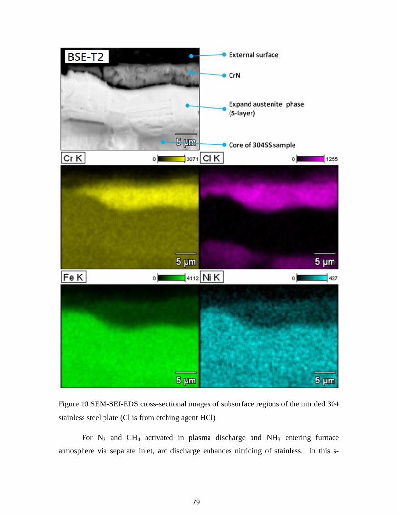
79
Figure 10 SEM-SEI-EDS cross-sectional images of subsurface regions of the nitrided 304
stainless steel plate (Cl is from etching agent HCl)
For N2 and CH4 activated in plasma discharge and NH3 entering furnace
atmosphere via separate inlet, arc discharge enhances nitriding of stainless. In this s-

80
phase layer, fine grain structure can be observed under SEM, the element concentration
didn’t change from the bulk material. It is speculated that the difference can be related to
a faster removal of passive film from stainless steel with arc-activated gases. Also,
plasma-activation promotes the growth of S-layer. Elemental analysis of the typical S-
layers decorated with nitrides, etched by acid is shown in Figure 9-10. It shows the
topography of the nitride, the S-layer and the parent metal, the Cr-enrichment and the
absence of a relatively non-reactive nickel (Ni) in the top nitride phase, the absence of
chlorine (Cl) in the S-layer indicating its increased resistance to acid attack, and the
uniform distribution of iron (Fe) across the material, except the Cr-enriched nitrides. It
suggests that after adjusting the time and temperature of the treatment, it is possible to
grow corrosion resistant S-layers without the use of expensive and toxic etchants or
vacuum plasma ion nitriding chambers.
4. Solution nitriding and carburizing
High temperature treatments were also conducted on the AISI 304 stainless steel
samples. Nitrogen gas is used as a nitrogen source not a protective atmosphere. At
temperatures above 1050°C (1920°F), stable nitrogen molecules can dissociate at metallic
surfaces into active nitrogen atoms. The dissociated nitrogen can despite the passive
chromium-oxide layer, penetrate the surface and diffuse into metal piece. AISI 304
stainless steel disks were used in this group of test, process temperature and time were
kept constant at 1100oC for 4 hour and only variable is atmosphere condition. Comparing
the non-activated (T5-thermal) nitrogen atmosphere run with electric-arc activated (T6-
arc) run, more nitrogen is picked up by parent metal, shown in Figure 11. The reaction is
clearly been accelerated and higher surface hardness and deeper case depth were
produced by arc-activated run. From the cross-section hardness profile, hardness
increased from 200 to 350 HK and several hundred micron case depth was generated,
shown in Figure 12.

81
Figure 11 Microstructure of solution nitriding 304 stainless steel, (a) non-activated
nitrogen atmosphere run, (b) electric-arc activated nitrogen atmosphere run.
Figure 12 Microhardness profile of solution nitridng and carburizing 304 stainless steel
(1100oC, 4hrs).

82
Small amount methane was added into process gas for T8 and 9. The test runs
with hydrocarbon gas have significantly larger weight gain and the extra weight pickup
during the process is due to the carbon diffusion. Pearlite was observed in the effective
case region (in Figure 13), and much higher hardness can be achieved by carbon diffused
into the base metal with larger case depth. From the Figure 13(b) microstructure photos,
1st layer (0~150micro): occuped with fine grains and nitrides, no carbides exist; 2nd
layer (150~600micro): carbides and pearlite shape grains start to exist; 3rd layer
(600~1500micro) large grains formed with pearlite. Nitrides and carbides seem don’t
precipitate in the same location. And more than 1mm hardening case was generated after
4 hour process. From the hardness result, methane runs have the highest hardness, which
have 450-500 HK surface hardness. According to OES results (shown in Figure 14),
carbon diffusion rate is higher than nitrogen, so carbon diffused into metal first, then
blocked the nitrogen penetration. This phenomenon resulted into high carbon pickup and
little nitrogen pickup in the process.
Figure 13 Microstructure of solution carburizing 304 stainless steel, (a) non-activated
nitrogen atmosphere run, (b) electric-arc activated nitrogen atmosphere run.

83
Figure 14 Surface concentration of N and C for solution treatment samples.
Conclusion In this study on the behavior of stainless steel under atmospheric heat treating
condition with nitrogen based process gas, the following key observations are made:
1. 80 µm thick nitrided layer was successfully generated using a novel, 4-hr long,
atmospheric-pressure gas treatment on 300-series austenitic stainless steel. High
hardness of 1000 ~1100 HK was observed at this layer.
2. Electric arc activation of nitrocarburizing atmosphere increases the growth rate of S-
layers by one order of magnitude. 15-20 µm S-layer was successfully formed after 4
hour process. But Cr-nitrides formed on top of the s-layer and lost corrosion
resistance. Lower temperature or shorter time should be used in the future test to
grow S-layer without CrN precipitates using arc activation.
3. Solution nitriding and carburizing at 1100oC with electric are activation have
improvement in hardness and larger case. And much higher hardness can be achieved
by carbon addition.

84
4. Simple and cheaper methods to case hardening stainless steel are successfully
demonstrated. With some optimizations, those processes can be used in commercial
heat treating facility in near future.
Acknowledgments The authors would like to thank J.L. Green for laboratory support and Air
Products for funding and the permission to publish this study.
References [1] ISSF announces, “Global stainless steel output figure for 2010”, url:
http://www.worldstainless.org/News/Media+releases/Stainless+steel+production+in
+2010.htm, last accessed: March, 2011
[2] Coates, G. and Jenkinson, D., “What is Stainless Steel?”, url:
http://www.nickelinstitute.org/index.cfm/ci_id/11021.htm, last accessed: April, 2011
[3] Wei, R et al, “A comparative study of beam ion implantation, plasma ion
implantation and nitriding of AISI 304 stainless steel”, Surface and Coatings
Technology, Volume 83, Issues 1-3, Pages 235-242, September 1996
[4] Blawert, C. et al, “Plasma immersion ion implantation of stainless steel: austenitic
stainless steel in comparison to austenitic-ferritic stainless steel”, Surface and
Coatings Technology, Volume 85, Issues 1-2, Pages 15-27, November 1996
[5] Collins, G. A. et al, “Nitriding of austenitic stainless steel by plasma immersion ion
implantation”, Surface and Coatings Technology, Volumes 74-75, Part 1, Pages 417-
424, September 1995
[6] Zhang, Z.L. and Bell, T., “Structure and corrosion resistance of plasma nitrided
stainless steel”. Surf. Eng. Vol 1 (2), 1985
[7] Christiansen, T. and Somers, M. A.J., “Characterization of low temperature surface
hardened stainless steel”, Struers Journal of Materialography, Sept., 2006
[8] Bell, T. and Li, C.X., “Stainless Steel: Low-Temperature Nitriding and
Carburizing”, Advanced Materials & Processes, Volume 160, Issue 6, 2002
[9] Buhagiar, J., Li, X. and Dong, H., “Formation and microstructural characterisation
of S-phase layers in Ni-free austenitic stainless steels by low-temperature plasma
85
surface alloying”, Surface and Coatings Technology, Volume 204, Issue 3, Pages
330-335, October 2009
[10] Gontijo, L.C. et al, “Study of the S phase formed on plasma-nitrided AISI 316L
stainless steel”, Materials Science and Engineering: A, Volume 431, Issues 1-2,
Pages 315-321, September 2006
[11] Tsujikawa, M. et al, “Effect of molybdenum and copper on S-phase layer thickness
of low-temperature carburized austenitic stainless steel”, Surface and Coatings
Technology, Volume 202, Issues 22-23, Pages 5488-5492, August 2008,
[12] Schmalt, F., Berns, H., and Zaugg, R., “Solution Nitriding—A New High
Temperature Nitriding of Stainless Steel”, Surface Engineering Coatings and Heat
Treatments 2002: Proceedings of the 1st ASM International Surface Engineering
and the 13th IFHTSE Congress, Pages: 88-97, Jan 2003
[13] Edenhofer, B., “Solution Nitriding - A Cost Effective Case Hardening Process for
Stainless Steels”, ASM Heat Treating Society Conference and Exposition, 2007,
COBO Center, Detroit, Michigan, USA
[14] Berns, H., “Case hardening of stainless steel using nitrogen”, Industrial heating, vol.
70, no5, pp. 47-50, 2003
[15] Kochmanski, P. and Nowacki, J., “Influence of initial heat treatment of 17-4 PH
stainless steel on gas nitriding kinetics”, Surface and Coatings Technology, Volume
202, Issue 19, Pages 4834-4838, June 2008,
[16] Tahara, M. et al, U.S Patent 5,792,282
[17] Du, H. and Agren, J., “Gaseous Nitriding Iron - Evaluation of Diffusion Data of N in
γ’ and ε Phases”, Solid Phase Transformations, 1994
[18] P.N. Kogyo, U.S. Patent 2007/0204934 A1
[19] Z. Zurecki et al, U.S. Patent 2008/0283153
[20] Zurecki, Z and Wang, X, “Atmosphere carburizing using electric discharge-activated
nitrogen-natural gas mixtures,” Heat Treating Conference and Exposition,
Indianapolis, Indiana, Oct 2009.
[21] El-Rahman, A.M. Abd et al, “Effect of N2 to C2H2 ratio on r.f. plasma surface
treatment of austenitic stainless steel”, Surface and coatings technology, vol.183,
p268-274, 2004

86
[22] Blawert, C. et al, “Characterisation of duplex layer structures produced by
simultaneous implantation of nitrogen and carbon into austenitic stainless steel
X5CrNi189”, Surface and coatings technology, vol.128, p219-225, 2000.

87
Paper 4: Evaluation of high Cr steels in cryogenic erosion environment (to
be submitted to Wear)
Abstract Cost-effective nitriding and carburizing methods for hardening surface of complex-
shaped mill rotors and screens by using conventional atmosphere box furnaces (at 1-atm
pressure) were evaluated. A series of stainless steels including 304, 316L, and 310 grades
were treated using these new methods to develop S-layer (expanded austenite) as well as
Cr-nitride/Cr-carbide and diffusional, solid solution layers. The surface treated coupons
together with high Cr cast iron and 17-4 PH steel were subsequently subjected to the
Al2O3-particle erosion wear testing at the liquid N2 temperature (-195oC) and room
temperature(+25oC). The results of the cryogenic erosion wear testing and case
hardening of stainless steel is reported.
1. Introduction
Growing industrial demand is noted for recycling polymers, rubbers, and electronic
waste, as well as contamination-free processing of foods and bioactive materials via
comminution and fine pulverizing. 1 Cryogenic temperature milling and grinding,
arguably the most suitable comminution techniques, may require further improvements to
meet this demand. Many researches have been done to enhance the erosion and abrasion
wear-life of mill components. 2-5
Improving wear resistance of cryo-mills is expected to
reduce operating costs, increase productivity and, in the case of bioactive food stock
products, and reduce contamination, i.e. enhance customers’ acceptance of cryogenic
milling.
Dry erosion has been assumed here as the predominant wear mechanism attacking
mill components during the cryo-pulverizing. There are very significant differences
between materials in their response to erosion depending on, among the other factors,
erosive particle impingement angle, kinetic energy, size, shape, hardness and process
temperature. Erosion of the steel depends on many aspects, the material properties, and

88
structures, physical and chemical properties of erodent particles, condition and
environment. On ductile materials the impacting particles cause severe, localized plastic
strain to occur that eventually exceeds the strain to failure of the deformed material. On
brittle materials, the force of the erodent particles causes cracking and chipping off of
microsize pieces.6-7
Many case hardening treatments, such as nitriding8, carburizing
9,
nitrocarburizing8,10
and boronizing11
may improve wear resistance on the surface by
forming a thin, hard case, with the supporting bulk material containing the required
mechanical properties.
It was therefore further assumed that cryomilling of bioactive-food stock products
takes place under milder, less erosive wear conditions, while cryomilling of minerals,
plastics (PVC) and composites presents the most aggressive conditions. A literature
review was carried out which identified a series of hard coatings, e.g. biocompatible
CVD TiCN, claimed to significantly enhance erosion wear resistance of various metallic
materials under a less energetic erosion attack, esp. if the erosive particle’s impingement
angle was steep.12
Since such solutions to milder erosion conditions appear to exist, it
was decided to focus on exploring high-energy cryo-erosion of metallic alloys considered
for abrasive, non-bio materials. The need for testing was further accentuated by a absence
of technical references describing erosion at cryogenic temperature.13
For annealed elements, greater hardness does not result in increased erosion wear
resistance. It is usually has no effect or a negative effect. At both low and high
impingement angle, high hardness steel has more severe erosion than low hardness
aluminum. The explanation of this phenomenon is that the mechanism of erosion wear is
different for high and low hardness materials. High hardness metals often tend to
generate more microcracking and surface fatigue that causes metal surface to be removed
by erosion particles. In the other hand, softer metals suffered more microcutting and
extrusion of material, which still attached to the base metals, so the volume% lost may be
even smaller than harder metals.14
The mechanical properties of the metals have great influence on erosion resistance.
Ductility, strain hardening, “malleability”, and thermal properties are more important,
than hardness, toughness, and strength. Higher ductility generally results in lower erosion

89
rates. Higher strength and hardness can result in significantly greater erosion occurring. It
can be seen that the less ductile, as-rolled steel has a higher erosion rate than the annealed
steel.
Many erosion tests have been done at the high temperature environment. Previous
research showed the erosion rate of 304 and 310 stainless steel at low angle contact angle
did not change much until the temperature reach 400oC and then followed by a rapidly
increasing; but at high contact angle, a minimum occur at 400oC.
9 Rarely literature can be
found which discussed the erosion properties at cryogenic temperature. But as the trend
shown on graphs, we can expect higher erosion rate at cryo temperature, and even a
significant increase below the ductility to brittle transformation temperature (DBTT).15
2. Experimental 2.1 Material
The materials subjected to the cryo-erosion testing included vendor supplied high- Cr
white cast irons (K1-K2), precipitation hardened 17-4PH stainless steel (K3), as well as a
series of austenitic stainless steels (304, 310, 316L) in as-supplied, annealed condition,
and after experimental nitriding and/or carburizing treatments condition, compositions
listed on Table 1.
Table 1 Nominal composition of the investigated high Cr alloys in weight%
Mo Mn Cr Nb Cu Ni C Fe
Cast iron 0.16 0.57 19.61 - - - - Bal
17-4 PH 0.09 0.73 15.06 0.23 3.21 4.33 - Bal
304 ss <2 17.5-20 - - 8-11 <0.08 Bal
310 ss <2 24-26 19-22 <0.25 Bal
316 L ss 2-3 <2 16-18.5 10-14 <0.03 Bal
2.2 Heat treatment

90
Three case hardening processes were designed based on previous experimental results
for austenitic stainless steel 304, 310 and 316L to generate wear resistance s-phase or Cr-
nitride/Cr-carbide.10, 16
Heat treatment experiments were run in a semi-production scale,
electrically heated box furnace, ATS 3350 at atmosphere pressure.
Figure 1 Case hardening test matrix for stainless steel coupons.
Three different case hardening processes were designed and performed on all the
stainless steel samples. They are (B) high temperature carburizing, (C) double treatment
(first carburized, then slightly polished to remove the oxidation layer, followed by low
temperature nitriding) and (D) low temperature nitriding. Fig. 1 presents the details of
thermochemical treatments performed. In (B) high temperature carburizing, the
specimens were held at 950oC for 4 h in 98%N2+2%CH4 atmosphere and quenched in
water. In (D) low temperature nitriding, the specimens were held at 565 o
C for 4 h in
73.75%N2+1.25%CH4+25%NH3 atmosphere and slowly nitrogen gas cooled in the
furnace to room temperature. The atmosphere was activated by AC-plasma. The cold
plasma, stream-activating injector was used in the process, equipment details were
described elsewhere.16-17
Optical microscopy and scanning electron microscopy (SEM)
were carried out to characterize the microstructure. Microhardness test was performed for
cross-sectional hardness profile to identify the case hardening depth.

91
2.3 Wear test
An erosion testing apparatus was fabricated and configured as shown in Fig. 2, and
angular, alumina particles were used as the erodent, showed in Fig. 3, with an average
particle size of 250-300 µm. The particle flowrate was kept constant at 28 g/min, and the
total eroding time was always 2.5 min, yielding the total mass flux of 70 g per test.
Calculated particle velocity was 17.5 m/s and the calculated speed of N2-propelling jet
was 140 m/s. The total kinetic energy imparted into an approximately 1.85-1.96 mm
(0.073”-0.077”) diameter nozzle on the surface of target material was 10.7 J. The erosion
stream was contacted with specimen at 90o. The test was performed at two different
temperatures: room temperature (25oC) and liquid nitrogen temperature (-195
oC). SEM
was used to observe the morphology of eroded surface after the tests.
Figure 2 The schematic graph of cryo grit-blasting test fixture.
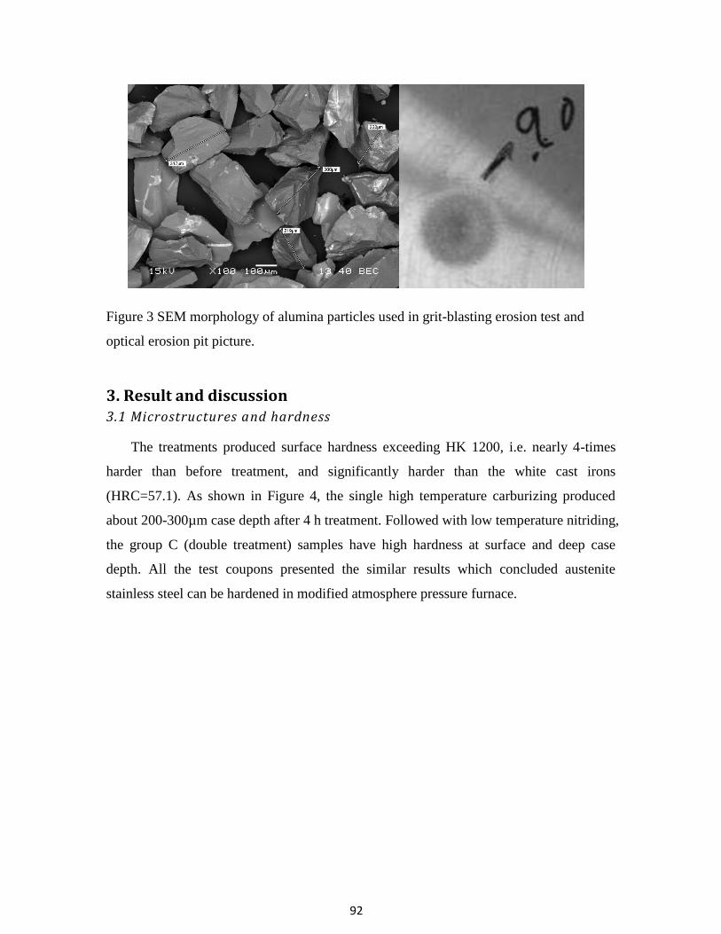
92
Figure 3 SEM morphology of alumina particles used in grit-blasting erosion test and
optical erosion pit picture.
3. Result and discussion 3.1 Microstructures and hardness
The treatments produced surface hardness exceeding HK 1200, i.e. nearly 4-times
harder than before treatment, and significantly harder than the white cast irons
(HRC=57.1). As shown in Figure 4, the single high temperature carburizing produced
about 200-300µm case depth after 4 h treatment. Followed with low temperature nitriding,
the group C (double treatment) samples have high hardness at surface and deep case
depth. All the test coupons presented the similar results which concluded austenite
stainless steel can be hardened in modified atmosphere pressure furnace.

93
Figure 4 Microhardness profiles of the case hardened 310 stainless steel specimens.
The feasibility of rapid nitriding and carburizing of austenitic stainless steels has
been demonstrated using cold plasma atmosphere activation system installed on
conventional, 1-atm pressure box furnace.19
The activated gases minimize the need for
surface preparation or halogen etching of stainless steel parts treated, perhaps due to the
generation of ions, atoms and radicals in the atmosphere. 17, 19

94
Figure 5 Cross-sectional microstructure of the (a) 4C (304ss-double treatment) and (b)
0D(310ss-low temperature nitriding) specimens.
Also, after 4 h nitriding, 310 stainless steel generated a 15µm S-phase with high
hardness, shown in Fig. 5(b). Compared to the ion sputtering, low-temperature plasma

95
surface alloying and other expensive process, the activated atmosphere process is really a
desirable alternative.
3.2 Erosion cavities
Erosion tests were performed on as-received stainless steel, case-hardened stainless
steel, high-Cr white cast irons and precipitation hardened stainless steel samples. Since
erosion is key factor in cryomilling, a new testing apparatus was developed to test erosion
rates of parts at cryogenic (LIN) temperature.
Figure 6 Relationship between surface hardness and depth of cavity eroded by grit
blasting at LIN-temperature. (28 g/min for 2.5 min with 17.5 m/s particle velocity and
140 m/s N2-propelling jet)
Erosion wear rate evaluation, based on the measurement of the depth of the pit
eroded by particles is shown in Fig. 6. The high Cr cast irons are characterized by a

96
significantly higher macro-hardness, but their cryo-erosion rates are much higher than
those of austenitic stainless steel or 17-4 PH stainless steel. Micro cracks are easily
forming during erosion test, shown in Fig, 7. Cast iron is harder but embrittled by LIN
and steels are worn faster due to fatigue microcracking. Also, the precipitation hardened
17-4PH stainless steel was less resistant than any of the austenitic stainless steels (304,
310 and 316L) tested.
Only two austenitic stainless steel samples performed markedly better than the rest:
the high-temperature carbo-nitrided 304 and the low-temperature nitrided 310. From the
depth of cavity generated by erosion jet, solution carburized 310 stainless steel (0B) gives
the best result. From the microhardness result, double treatment 304 stainless steel (4C)
shows the highest hardness. But these results necessitate nevertheless more investigations
since the depth of the pit eroded in those (and the other thermochemically treated)
samples was always larger than the thickness of the hardened layer, Fig. 8-9. And also
there is no significant hardness - wear rate correlation was found under cryogenic wear
tests. Material hardness cannot be used for predicting erosion rates of different materials.
Austenitic stainless steels (300-series) wear less under conditions tested than hard but
brittle cast irons or 17-4 PH stainless steels. Prediction of cryo-erosion rates based on
room temperature macro-hardness (HRC, HRB, HRA, HB or HV) data is also unreliable.
Figure 7 Cracks near cavity pit area for cast iron K1.

97
Figure 8 Morphology of erosion cavity for 0D specimen.

98
Figure 9 Morphology of erosion cavity for 6B specimen.
Figure 10 shows the local wear pattern very close to the pit point for different
material under room temperature or cryogenic temperature. Both individual particle
impact and the flakes which are formed plastically due to particle impacts can be
observed. By compared the morphology of cavity pits area between the room temperature
and cryogenic temperature specimens, it also showed steel coupons are more brittle under
low temperature.

99
Figure 10 Micrographs of pits area taken by SEM
3.3 DBTT vs. wear resistance
Correct prediction of cryo-erosion performance of materials using an easily available,
room temperature data is a matter of practical interest. Hence, room temperature, jet-
erosion tests were run on selected specimens and their results were compared to those
obtained during cryo-erosion tests, Fig. 11. Not surprisingly, lowering the test
temperature results in accelerated erosion of all materials, but the erosion rate difference
is very different for different materials to the point of changing their original ranking.
Thus, the white cast iron, brittle at room and LIN temperatures, as well as the ductile
austenitic stainless steel erode somewhat faster in LIN, but the 17-4 PH stainless steel,
ductile at room temperature and turning brittle in LIN, loses more than 40% of its original
erosion resistance. The increase in erosion rate with reducing temperature is most
significant for materials which turn brittle during cooling. Room-temperature ranking of
materials for cryogenic wear service may lead to incorrect predictions due to ductility
change during cooling.

100
Figure 11 Depth of eroded cavity as a function of temperature and material ductility
(changing material ranking).
Consequently, material selection for cryo-milling service must be based on tests
performed at cryogenic temperature. Given the fact that erosion rates are further modified
by impingement angles, kinetic energy, size, and shape of eroding particles, the only
reliable selection of materials for cryo-milling operations should be based on tests in
actual milling equipment or, at least, small scale cryo-milling equipment simulating the
real production conditions.
4. Conclusion Cryogenic temperatures accelerate erosive wear of pulverizing tools by promoting
brittle surface fracturing and fatigue chipping. Retention of ductility at cryo-temperature
is critical for erosion resistance. The wear rate rankings as well as hardness values
measured in room temperature cannot be used for predicting wear resistance in cryogenic
temperatures. Although 304/310/316L wears more than 17-4 PH steels at room
temperature, it doesn’t suffer the sudden increase in wear rate as the temperatures drop to
-195oC.

101
The effect of case hardening on reducing cryogenic erosion wear is positive but not
significant, regardless of the treatment used, because the worn areas usually extend deep
into parent metal. Nevertheless, it is plausible that case hardening could be cost-effective
in the cryo-milling applications involving softer feedstock material and/or sliding or
abrasion wear modes.
The rapid nitriding and carburizing of austenitic stainless steels has been
demonstrated using new, cold plasma atmosphere activation system installed on
conventional, 1-atm pressure box furnace. The activated, N2-NH3-hydrocarbon gases
minimize the need for surface prep or halogen etching of stainless steel parts treated,
perhaps due to the generation of ions, atoms and radicals in the atmosphere. Planned
refinement of the new method will involve control of nitrogen and carbon mass fluxes
from the atmosphere to metal surface.
5. Reference 1. Air Products, Cryogenic griding, url:
http://www.airproducts.com/Products/Equipment/Cryogenics/Chemicals/grinding.
htm, (2010)
2. S. S. Gill, H. Singh, R. Singh and J. Singh, Cryoprocessing of cutting tool
materials—a review, The International Journal of Advanced Manufacturing
Technology, 48 (2009) 175-192
3. R. Singh, and K. Singh, Enhancement of Tool Material Machining Characteristics
with Cryogenic Treatment: A Review, Proceedings of the 2010 International
Conference on Industrial Engineering and Operations Management, Dhaka,
Bangladesh, January 9 – 10, 2010
4. A.Y.L. Yong, K.H.W Seah, and M. Rahman, Performance of Cryogenically
Treated Tungsten Carbide Tools in Milling Operation, International Journal of
Advanced Manufacturing Technology, 32 (2007) 638-643,
5. M. Preciado, P.M. Bravo and J.M. Alegre, Effect of low temperature tempering
prior cryogenic treatment on carburized steels, Journal of Material Processing
Technology, 176 (2006) 41–44

102
6. A.V. Levy, Gas-solid particle erosion and erosion-corrosion of metals, Uhlig’s
corrosion handbook, (2000) 273-293,
7. E. Rodríguez, M. Flores, A. Pérez, R.D. Mercado-Solis, R. González, J.
Rodríguez, S. Valtierra, Erosive wear by silica sand on AISI H13 and 4140 steels,
Wear, 267(2009) 2109–2115
8. G. Nivoletto, A. Tucci, L. Esposito, Sliding wear behavior of nitrided and
nitrocarburized cast irons, Wear 197 (1996) 38–44.
9. B.S. Suh, W.J. Lee, Surface hardening of AISI 316L stainless steel using plasma
carburizing, Thin Solid Film 295 (1997) 185–192.
10. D. Wen, Erosion and wear behavior of nitrocarburized DC53 tool steel, Wear,
268(2010) 629–636
11. N.Y. Sari, M. Yilmaz, Investigation of abrasive + erosive wear behaviour of
surface hardening methods applied to AISI 1050 steel, Mater. Design 27 (2006)
470–478.
12. E. Bemporada, and et al., High thickness Ti/TiN multilayer thin coatings for wear
resistant applications, Surface and Coatings Technology, 201(2006) 2155-2165
13. K.H. Zum Gahr, Microstructure and wear of materials,(1987) 534-537,
14. A.V. Levy, Solid particle erosion and erosion-corrosion of materials, (1995)
36,75-80
15. T. Becker, Roch J. Shipley, ASM Handbook: Failure analysis and
preventionWilliam, (2002) p690-694
16. Zurecki, Z and Wang, X, Atmosphere carburizing using electric discharge-
activated nitrogen-natural gas mixtures, Heat Treating Conference and Exposition,
(2009), Indianapolis, Indiana
17. Z. Zurecki et al, U.S. Patent 2008/0283153

103
CHAPTER IV
RESEARCH CONCLUSIONS
This thesis presents a series of experimental investigating activated atmosphere case
hardening of a variety of steels. Corresponding to the research objectives in Chapter I, the
following conclusions are drawn.
The steel carburizing process in 1-atm-pressure furnaces that non-equilibrium
atmospheres containing methane (Appendix A) and propane gases (Paper 1) was
evaluated. A cold, non-equilibrium plasma system has been explored and successfully
demonstrated in this research with many benefits, for example, the system is easy to
install in the conventional furnaces, minimized IGO, and saving cost and energy.
Measurements of carbon mass flux and calculations of carbon potential in gas phase have
shown that the present carburizing rates are comparable to those of low-pressure (vacuum)
and endothermic atmosphere carburizing systems. Carburizing effects were compared for
the AISI 8620 steel coupons processed with the N2-C3H8, N2-CH4 mixture and the
conventional endothermic atmosphere using the same heat treatment schedule. The
microhardness profile directly under metal surface was relatively flat, similar as by low-
pressure carburizing, and will be beneficial from the post-machining and fatigue strength
standpoint. Modified shim stock method and probe can be used for determining carbon
flux from atmosphere into metal combined with diffusion calculations for carbon
concentration profile at and under metal surface. Carbon flux measurements can be
correlated with H2 concentration and, optionally, with other gas sensors. Controlling
hydrocarbon gas concentration during the subsequent, production operations, where
carbon flux measurements are no longer used as long as the HC additions result in the
same H2 during the recipe development run.
In this experimental study (Paper 2 and 3) on the behavior of carbon steel, alloy steel
and stainless steel with diluted ammonia, the following key observations are made: 15µm
white layer with 150-200µm case depth was generated for carbon and alloy steel after 4
hours treatment which is much faster than conventional nitriding rate. 80 µm thick
compound layer was successfully generated using a novel, 4-hr long, atmospheric-

104
pressure gas treatment on 300-series austenitic stainless steel. High hardness of 1000
~1100 HK was observed at this layer. Electric arc activation of nitrocarburizing
atmosphere increases the growth rate of S-layers by one order of magnitude. But Cr-
nitrides formed on top of the s-layer and lost corrosion resistance. Lower temperature or
shorter time could be used in the future test to grow S-layer without CrN precipitates
using arc activation. Solution nitriding and carburizing at 1100oC with electric are
activation have improvement in hardness and larger case. And much higher hardness can
be achieved by carbon addition. Simple and cheaper methods to case hardening stainless
steel are successfully demonstrated. With some optimizations, those processes may be
used in commercial heat treating facility in near future.
Erosion resistance at cryogenic temperatures is also evaluated for high Cr
steels.(Paper 4) Cryogenic temperatures accelerate erosive wear of pulverizing tools by
promoting brittle surface fracturing and fatigue chipping. Retention of ductility at cryo-
temperature is critical for erosion resistance. The wear rate rankings as well as hardness
values measured in room temperature cannot be used for predicting wear resistance in
cryogenic temperatures. Although 304/310/316L wears more than 17-4 PH steels at room
temperature, it doesn’t suffer the sudden increase in wear rate as the temperatures drop to
-195oC. The effect of case hardening on reducing cryogenic erosion wear is positive but
not significant, regardless of the treatment used, because the worn areas usually extend
deep into parent metal. Nevertheless, it is plausible that case hardening could be cost-
effective in the cryo-milling applications involving softer feedstock material and/or
sliding or abrasion wear modes. The rapid nitriding and carburizing of austenitic stainless
steels has been demonstrated using new, cold plasma atmosphere activation system
installed on conventional, 1-atm pressure box furnace. The activated, N2-NH3-
hydrocarbon gases minimize the need for surface prep or halogen etching of stainless
steel parts treated, perhaps due to the generation of ions, atoms and radicals in the
atmosphere. Planned refinement of the new method will involve control of nitrogen and
carbon mass fluxes from the atmosphere to metal surface.
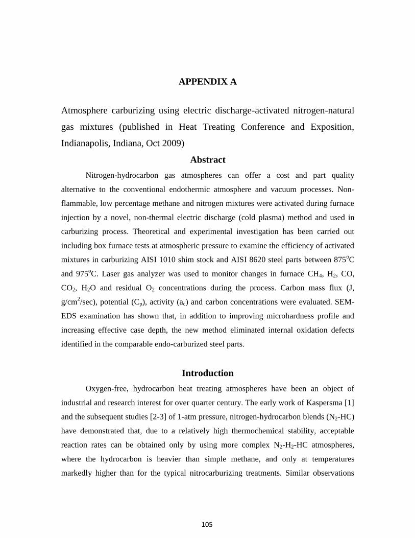
105
APPENDIX A
Atmosphere carburizing using electric discharge-activated nitrogen-natural
gas mixtures (published in Heat Treating Conference and Exposition,
Indianapolis, Indiana, Oct 2009)
Abstract
Nitrogen-hydrocarbon gas atmospheres can offer a cost and part quality
alternative to the conventional endothermic atmosphere and vacuum processes. Non-
flammable, low percentage methane and nitrogen mixtures were activated during furnace
injection by a novel, non-thermal electric discharge (cold plasma) method and used in
carburizing process. Theoretical and experimental investigation has been carried out
including box furnace tests at atmospheric pressure to examine the efficiency of activated
mixtures in carburizing AISI 1010 shim stock and AISI 8620 steel parts between 875oC
and 975oC. Laser gas analyzer was used to monitor changes in furnace CH4, H2, CO,
CO2, H2O and residual O2 concentrations during the process. Carbon mass flux (J,
g/cm2/sec), potential (Cp), activity (ac) and carbon concentrations were evaluated. SEM-
EDS examination has shown that, in addition to improving microhardness profile and
increasing effective case depth, the new method eliminated internal oxidation defects
identified in the comparable endo-carburized steel parts.
Introduction
Oxygen-free, hydrocarbon heat treating atmospheres have been an object of
industrial and research interest for over quarter century. The early work of Kaspersma [1]
and the subsequent studies [2-3] of 1-atm pressure, nitrogen-hydrocarbon blends (N2-HC)
have demonstrated that, due to a relatively high thermochemical stability, acceptable
reaction rates can be obtained only by using more complex N2-H2-HC atmospheres,
where the hydrocarbon is heavier than simple methane, and only at temperatures
markedly higher than for the typical nitrocarburizing treatments. Similar observations

106
were made in the area of vacuum carburizing where the initial practice of CH4
carburizing at a fairly high partial pressure was gradually replaced by a low partial
pressure carburizing in acetylene, ethylene, or propane-hydrogen multi-component blends
[4-5]. This shift away from inexpensive CH4 blends is not surprising in view of the recent
HC dissociation data [6-7] as well the authors’ own thermogravimetric measurements
(TGA) illustrated in Fig. 1. The plots represent the carburization weight gain of AISI
1010 carbon steel coupons exposed to six different, non-flammable/non-explosive N2-HC
blends during a 10oC/minute temperature ramp-up. Results confirm that methane is
practically nonreactive with steel up to 1000oC (1830
oF). Acetylene starts an effective
carburizing from about 700oC (1300
oF), while propylene, propane (mixed with hydrogen
or not), and ethylene become carburizing at the temperature 100oC-150
oC higher. An
important advantage of both the low-pressure and the 1-atm pressure hydrocarbon
atmospheres over the conventional endothermic atmospheres is the absence of
intergranual oxidation (IGO) of Mn, Si and, in the case of alloyed or microalloyed steels,
also Cr, Al, Ti, or Zr [8-10]. Since IGO reduces fatigue strength, steel parts processed
under endo-atmospheres require longer carburizing cycles, deeper carburized cases, and
more stock to be ground-off during the subsequent machining. Marginally successful
attempts to counter the endo-atmosphere resultant IGO by adding ammonia in the last
minutes of carburizing [11] point to the value of hydrocarbon atmospheres in processing
of plain as well as low and highly alloyed steels.
-1.00E-01
0.00E+00
1.00E-01
2.00E-01
3.00E-01
4.00E-01
5.00E-01
6.00E-01
7.00E-01
8.00E-01
9.00E-01
1.00E+00
250 350 450 550 650 750 850 950
∆ W
eigh
t, m
g/cm
2
Temperature, ℃
N2-4.5CH4
N2-2%C3H6
N2-2%C2H2
N2-2%C3H8
N2-2%C3H8-2%H2
N2-2%C2H4

107
Figure 1: TGA results of carburizing steel in non-flammable, thermally activated
nitrogen-hydrocarbon gas blends at 1-atm pressure.
Against this background, the objective of present work is to explore the feasibility
of carburizing steels in simple, non-toxic and non-flammable N2-CH4 atmospheres, with
the CH4 concentration kept below the low explosivity limit (LEL), which are activated at
the inlet to heat treating furnace by a cold (non-thermal) plasma electric discharge.
Experimental procedure
1. Cold Plasma Carburizing System
A series of gas stream-activating, cold-plasma injectors have been developed at
Air Products during the recent few years. Described elsewhere [12], the injectors
comprise two high voltage electrodes positioned across the stream of gas directed from
gas supply into heat treating furnace. A DC or AC source-powered electric discharge
between these electrodes ionizes, partially dissociates and converts the gas molecules on
their way into the furnace. In contrast to the conventional, low-pressure plasma ion
furnaces, metal load is not an electrode. A high-voltage/low-amperage, low power supply
is used (typically below 1 kW) which forms a cold discharge combining self-pulsed, non-
equilibrium arc and abnormal glow plasma modes [13] inside the passing gas stream. The
low thermal energy of the discharge assures long electrode lifetime and prevents gas
pyrolysis and sooting. Numerous long- and short-lived, equilibrium and non-equilibrium
gas products are formed in the N2-CH4 blend passing the discharge.

108
Figure 2: Cold plasma activated gas injection system
They include ions, radicals, excited CH4 and various byproducts: C2H2, C3H6,
C2H4, CH3, CH2, C3H8, H2, H, N, etc. [14-17], all readily reacting inside furnace and
accelerating reducing and carburizing reactions at the surface of metal load. The plasma
gas injectors can be easily retrofitted to various types of the conventional, radiant tube or
electrically heated, 1-atm pressure and vacuum furnaces in order to carry out carburizing,
carbonitriding, neutral carbon or “inert” annealing, as well as nitrocarburizing operations
falling into a relatively low temperature range. Fig. 2 shows schematic of atmospheric,
carburizing furnace equipped with the plasma gas injection retrofit.
The primary carburizing reaction involves plasma activated hydrocarbon
molecules, CmHn, and metal surface. Additional, oxygen reducing reactions may also take
place in the case of air infiltration of the furnace or air leakage which results in formation
of trace quantities of gases contained in the conventional endo-atmospheres. These
products may, in turn, lead to secondary carburizing reactions listed in Table 1. Cold
plasma carburizing process can be controlled using a modified version of the
conventional (thermal), low-pressure (vacuum) and atmospheric pressure modeling
approaches developed by the Center for Heat Treating Excellence at Worcester
Polytechnic Institute [18] and represented in Fig. 3.

109
Table 1: Reactions in atmospheric pressure furnace
Primary carburizing reaction:
m CH4 CmHn + (2m –n/2) H2
CmHn = m C + n/2 H2
ac = {K p(CmHn) p(H2)-2/n
}1/m
Reduction of oxygen contaminant:
O2 + CmHn = CO + H2O
O2 + H2 = H2O
H2O + CmHn = CO + H2
CO + H2O = CO2 + H2
CO2 + CmHn = CO + H2
Secondary carburizing reaction:
CO + H2 = C + H2O
ac = K p(CO) p(H2) / p(H2)
where: CmHn - plasma activated hydrocarbon, p – gas
partial pressure, ac – activity of carbon in gas phase, and K
= K(T) – reaction equilibrium constant

110
Figure 3: Carbon transport in gas carburizing
Expressions (1-5) combine the main control factors for the N2-CH4 plasma
carburization: total gas feed rate through plasma injector, CH4 concentration in the feed
stream, plasma power applied, process time and temperature, as well as furnace flow field
and furnace heaters characteristics. Optional gas analysis of the flue stream could be used
for monitoring H2, H2O, CO, CO2, and/or residual CH4 to detect operational or furnace
problems.
(1) p* – Cs)
(2) Cp* = Cp {p(CmHn)}
(3) p(CmHn) = f {CCH4, Eactiv, Tf, Th}
(4) Eactiv = Pplasma/QN2-CH4
(5) Jt
where: J - carbon mass flux in activated hydrocarbon atmosphere, g/cm2
- mass transfer coefficient, a function of gas properties and flow field F, cm/sec, Cp* -
apparent carbon potential of activated hydrocarbon atmosphere, a function of activated
111
hydrocarbon partial pressure, wt%, g/cm3, Cs = Cs(Tf, t) - carbon content at steel surface,
a function of furnace temperature, Tf, and time, t, wt%, g/cm3, p(CmHn) - partial pressure
of activated hydrocarbon gases, a function of CH4 concentration in the feed stream, CCH4,
plasma energy absorbed by the N2-CH4 feed stream, Eactiv, furnace temperature, Tf, and
furnace heaters temperature, Th, Pplasma/QN2-CH4 - plasma discharge power per mass
flowrate of the N2-CH4 feed stream, J/g, and Jt - time averaged carbon flux measured by
g/cm2/sec.
2. Procedures
Atmosphere carburizing experiments were run in a semi-production scale,
electrically heated box furnace, ATS 3350, configured as in Fig. 2. The inlet
concentration of CH4 in N2-stream was always kept below LEL (5 vol %), and no air was
intentionally added to the furnace. In the first part of test program, shim stock coupons
were exposed to carburizing atmospheres to assess carbon flux, apparent carbon
potential, and carbon activity in gas phase. In the second part of tests, real production
parts were carburized, quenched in oil, and tempered in order to compare the plasma
activated carburizing to the conventional, endothermic atmosphere carburizing.
Three different thickness levels of AISI 1010 steel shim stock, 4 x4 in2 (103.2
cm2) were used: 0.004- - 1-
Carburization of these specimens was performed according to the conditions given in
Table 2. Test 1 was performed under non-activated gas atmosphere; the others used AC-
plasma activation. Each carburization cycle involved 0.5-hour long heating of acetone-
degreased specimens from room to treatment temperature under pure N2, 3-hour
carburizing and 3-hour cooling with furnace to room temperature under pure N2. The
and
final weight, mf, were used to determine the apparent atmosphere carbon potential, Cp*,
according to equations 5 and 6, where Co, the initial carbon was 0.1 wt%.
(6) Cp* = 100 Jt f + Co f + Co
Production parts were investment cast and machined AISI 8620 steel rings (R), 44 mm
dia, and shafts (S), 14 mm dia. Table 3 presents nominal composition of the steel used.

112
Table 2: Shim stock carburizing conditions
Test No. T1 T2 T3 T4
Temperature (℃) 875 875 975 975
Carburizing Time(hr) 3 3 3 3
Plasma activation None Yes Yes Yes
Gas Flowrates, scfh (Nm3/h at 0
oC)
Total gas flowrate 250 (6.7) 250 (6.7) 250 (6.7) 500 (13.4)
N2-thru-plasma 0 239 (6.4) 239 (6.4) 478 (12.8)
CH4-thru-plasma 0 11 (0.29) 11 (0.29) 22 (0.58)
Furnace inlet CH4
(vol %) 4.5 4.5 4.5 4.5
Three pairs of R and S parts were tested: the 1st was endo-atmosphere carburized
at a commercial heat treating shop using an integral quench furnace and ZrO2-probe
control, the 2nd
was carburized using DC-plasma activation, and the 3rd
was carburized
using AC-plasma activation, both in the ATS box furnace. The endo-atmosphere
treatment was executed as follows: the parts were loaded to hot furnace at 900oC with
the carbon potential, Cp, maintained at 0.95 wt%C and boost-carburized for 2.5 hours,
then, diffused at Cp of 0.8-0.9 wt%C for 0.5 hours at the temperature reduced to 843oC,
quenched in oil tank inside the furnace and, finally, low-tempered at 180oC for 2 hours.
The DC and AC plasma-activated carburizing treatments were executed in a somewhat
simplified way: the parts were loaded to hot furnace filled only with a technically pure
N2 (99.995%) at 900oC, the CH4 flow and plasma power were turned on after part
loading. Only one total gas flowrate of 300 scfh and CH4 inlet concentration of 4.6vol%
was used during the subsequent 2.5-hr boosting at 900oC and 0.5-hr diffusing at 843
oC.
The parts were manually transferred through ambient air into an external oil bath at the
end of diffusing step. The last, 2-hr tempering step at 180oC was carried out under a
plasma-activated, N2-2.2 vol%CH4 stream.

113
Table 3: AISI 8620 steel composition (wt. %)
C Mn P S Si Ni Cr Mo
0.18-
0.23 0.7-0.9 <0.03 <0.04
0.15-
0.35 0.4-0.7 0.4-0.6
0.15-
0.25
Laser gas analyzer (LGA), manufactured by APW, model LGA-4ENAPBT, was
used to measure the inlet and the flue gas concentrations throughout the entire testing
program. H2, CH4, CO, CO2, O2, N2 and H2O concentrations were tracked with accuracy
of 1ppm. Superficial hardness HR15N on the outer diameters, and Vickers microhardness
profiles, 300 g load @ 10 sec, were taken for the fully carburized, quenched, and
tempered R and S parts. Metallographic cross-sections of the parts were etched with 2%
Nital prior to SEM examination.
Result and discussion
Apparent carbon potential of N2-CH4 atmospheres calculated from eq. 6 for the
fixed carburizing time of 3 hours was higher than typical carbon potentials expected in
the conventional endothermic atmospheres, Table 4. This is not surprising in view of
literature references on O2-free, HC atmospheres [1-2 and 19] where the equilibrium
products of HC carburizing are cementite (6.67 wt%C) or soot. Interestingly, the apparent
due to the fact that the thinner shim saturated with carbon faster.
Table 4: Carbon potential and carbon activity in gas phase
Test
No. T1 T2 T3 T4
Apparent carbon potential calculated from weight
gain measurements, Cp*, wt% C
0.004'' 2.04 2.74 3.40 2.44
0.015'' 0.89 1.63 1.79 1.75
Carbon activity in gas phase calculated from H2 and
CH4 concentrations in furnace, ac
ac 1.9E+05 4.6E+04 1.8E+04 7.2E+04

114
Additional diffusion modeling work was performed using the CarbTool software
referenced in [18] which confirmed the saturation effect rather than the presence of a
carbon gradient in the thicker shim coupons. Carbon activity in gas phase was calculated
per procedure described in [19] using averaged LGA measurements of H2 and CH4
concentrations in the furnace flue stream for the gas carburizing reaction of CH4 = C +
2H2 which ignores plasma activation effects. Chemical Reaction and Equilibrium
Software, Outokumpu HSC Chemistry® for Windows with JANAF database, version 5.1
02103-ORC-T, was used for the activity calculations.
0.0E+00
5.0E-08
1.0E-07
1.5E-07
2.0E-07
2.5E-07
3.0E-07
3.5E-07
4.0E-07
4.5E-07
T1 T3 T4
Car
bo
n F
lux,
g/c
m2/s
0.004" 0.015" 0.031"
Reference data:•Endo gas.•3 hr Carburized at 930℃.•Cp=0.8 wt%
Figure 4: Effect of shim stock thickness on carbon flux measurement (3hr carburizing,
N2- 4.5 vol% CH4)
The results shown in Table 4 clearly indicate that the activity was orders of
magnitude higher than in the case of conventional endothermic atmospheres but, also,
deviated from the carbon potential. Thus, ac was the highest for a marginally carburizing
T1 condition and the lowest for the most carburizing, plasma-activated condition T3. This
spread between the weight gain based Cp* values and the atmosphere composition based
ac values is the direct evidence of the plasma activation effect.

115
0.0E+00
5.0E-08
1.0E-07
1.5E-07
2.0E-07
2.5E-07
3.0E-07
0.00%
0.20%
0.40%
0.60%
0.80%
1.00%
1.20%
1.40%
1.60%
T1 T2 T3 T4
Car
bo
n f
lux(
g/c
m2
/s)
H2
co
nce
ntr
atio
n (
vol%
)
H2(%) Carbon flux( g/cm2/s)
Plasma500SCFH
Thermal250SCFH
Plasma 250SCFH
Figure 5: Thermal and plasma carburizing using N2-4.5 vol% CH4 gas blend (AISI 1010
steel, 0.015” shim stock)
Just like in the case of low-pressure (vacuum) carburizing and, to a large degree
in endo-atmosphere carburizing, carbon mass flux is, perhaps, the most practical measure
of the plasma-activated carburizing process that enables the operator to compare various
process conditions and predict outcomes.
Fig. 4 and 5 show the effect of shim stock thickness, process temperature, and N2-
4.5 vol%CH4 gas blend flowrate at fixed plasma power input on carbon flux, Jt, averaged
over a 3-hour exposure. Thus, the plasma activated conditions T3 and T4 produced at
least as high flux values as the endo-atmosphere carburizing evaluated in [20] or vacuum
furnace carburizing with propane [21]. On the other hand, the non-activated, purely
thermal condition T1 resulted in an unacceptably low carbon flux, even though its ac and
Cp* values were high. In the plasma activated runs T2-T4, carbon flux scales much more
with the plasma energy absorbed by the incoming gas, Eactiv, eq. 4, and furnace
temperature, than with the degree of CH4 dissociation indicated by the level of H2 in
atmosphere shown in Fig. 5. It is concluded that the formation of active CmHn groups
plays a critical role in cold plasma carburizing. Fig. 6 illustrates the typical carburizing,
oil quenching, and tempering treatment cycle of the production parts R and S processed
with the AC and DC cold plasma system. For the boosting and diffusing steps, the flue

116
stream analysis was as follows: CH4 ≤4.4 vol%, H2<1.0 vol%, CO2<0.1 vol%, CO<0.05
vol%, H2O< 50 ppm (dew point below -48oC or -54
oF) and O2 below the LGA detection
limit of 1 ppm. Oxygen adsorbed on furnace refractories, oxide films, and a minute air
leakage were the most likely sources of oxygen detected in the effluent. The trace level of
the gases required for the secondary, ‘endo-like’ carburizing reaction provided no support
for the conventional ac and Cp calculations proposed first by Collin et al. [22] and
indicated that only the primary reaction, CmHn = m C + n/2 H2, was operational. For the
tempering step, where the inlet CH4 level was reduced, the concentrations of the flue
components were correspondingly lower. Of note, the conversion of the CH4 injected and
the H2 production scaled with the furnace temperature throughout the treatment cycle.
0
200
400
600
800
1000
1200
0
5000
10000
15000
20000
25000
30000
35000
40000
45000
50000
0 100 200 300 400
Tem
pe
ratu
re ,
C
pp
m
time, min
ppmv COppmv H2ppmv CH4ppmv CO2Temp
CH4
CH4
H2
H2CO&CO2
CO & CO2
900C, 2.5hr
843C, 0.5hr
180C, 2hr
Figure 6: Laser Gas Analysis record of AC plasma carburizing of R and S parts

117
89.5 89.0 89.389.1 89.1 89.4
80.0
82.0
84.0
86.0
88.0
90.0
92.0
Endo DC AC
HR
15
N
R-part S-part
Figure 7: Hardness HR15N of endo-atmosphere and plasma (DC and AC) carburized, oil
quenched, and tempered ring (R) and shaft (S) parts
Superficial hardness measurement is a convenient method of spot-checking part
quality in a stabilized carburizing heat treatment processes. The superficial hardness
HR15N of the endo-atmosphere, DC-plasma, and AC-plasma carburized and heat treated
parts R and S was measured and found to be identical within a narrow range of
measurement error, Fig.7. A far more complete picture of a carburizing heat treatment
process is obtained by a microhardness profiling as shown in Fig. 8 and 9.
100
200
300
400
500
600
700
800
0 200 400 600 800 1000 1200 1400 1600
Cro
ss-s
ect
ion
Har
dn
ess
HV
@ 3
00
G
Depth below surface, micrometer
DC-R
AC-R
Endo-R
Figure 8: Vickers microhardness profile for endo-atmosphere and plasma (DC and AC)
carburized, oil quenched, and tempered ring (R) parts

118
Although the surface hardness of all samples was nearly identical, the cross-
section hardness profile exhibited differences. The DC and AC plasma samples displayed
a higher hardness level (higher carbon content and/or lower retained austenite) going
deeper into the part with a sharper drop-off in the core area than the endo samples. This
type of hardness profile is valuable, especially, in the case of parts requiring an additional
finish-machining of the surface for restoring dimensional accuracy. Evaluated as in [23],
the effective case depth (ECD) for 50 HRC in the plasma carburized parts was 0.700 mm
(0.0276 inches), i.e. somewhat larger than in the endo-atmosphere carburized parts.
Analyses of the furnace atmosphere gases as well as the steel carburizing data have
shown that the DC and the AC powered electric discharges are comparable from the
effectiveness standpoint.
100
200
300
400
500
600
700
800
0 200 400 600 800 1000 1200 1400 1600Cro
ss-s
ecti
on
Har
dn
ess
HV
@ 3
00
G
Depth below surface, micrometer
DC-S
AC-S
Endo-S
Figure 9: Vickers microhardness profile for endo-atmosphere and plasma (DC and AC)
carburized, oil quenched, and tempered shaft (S) parts
Secondary electron images (SEM-SEI) of cross-sections of the endo-atmosphere
and the plasma carburized parts S, and the corresponding, elemental maps of Mn, Cr and
Si were acquired using energy-dispersive X-ray spectroscopy (EDS) probe, Fig. 10. The
endo-carburized part revealed a clearly developed intergranular oxidation zone with the
depth that agrees with the diffusional calculations and experimental data presented in [8].
The enrichment of the oxidized boundaries with Mn, Cr and Si was observed and

119
Figure 10: SEM-SEI-EDS cross-sectional images of subsurface regions of production
parts S after the completed carburizing, quenching and tempering cycle. (a) SEI image of
endo-atmosphere carburized part; (b-c) Mn and Cr EDS-maps of area (a), (d) higher
magnification of area (a), (e) Si EDS-map of area (d); and (f) SEI image of AC-plasma
carburized part.

120
explained by a higher affinity of those Fe-alloying elements for oxygen and oxygen-
containing gases always present in all types of endothermic carburizing atmospheres [11].
In contrast, no IGO effect was observed in the AC and DC plasma carburized samples
that exhibited a vacuum-carburizing quality of surface and subsurface material.
Conclusions
1. Cold, non-equilibrium plasma system has been explored and successfully
demonstrated in carburizing steels at 1-atm pressure using CH4-lean, non-
flammable/non-explosive N2-CH4 atmospheres. Easy to install in the conventional
furnaces, the system minimizes environmental pollution and offers a nearly 100%,
instant turndown ratio. The DC and the AC electric discharges were found to be
comparably effective in the activation of gas stream during injection and carburizing
of metal surface.
2. Steel carburizing reactions and process kinetics were evaluated. The surface reaction
with excited hydrocarbons produced during the passage of CH4 through plasma
discharge appears to dominate the process. Measurements of carbon mass flux and
calculations of carbon potential and activity in gas phase have shown that the present
carburizing rates are comparable to those of low-pressure (vacuum) and endothermic
atmosphere carburizing systems, but the thermodynamic equilibrium cannot be
established. Nevertheless, process control is simple, carbon flux based, and the
popular, low-pressure carburizing models are applicable.
3. Carburizing effects were compared for the AISI 8620 steel rings and shafts processed
with the plasma-activated N2-4.5 vol%CH4 mixture and the conventional endothermic
atmosphere using the same heat treatment schedule. The plasma atmosphere
processed parts were completely IGO-free and revealed a somewhat deeper effective
carburized depth. The microhardness profile directly under metal surface was
relatively flat, reminding the profiles obtained by low-pressure carburizing, and
beneficial from the post-machining and fatigue strength standpoint. In contrast, the
endo-atmosphere carburizing resulted in IGO defects, with the associated Mn, Cr and
Si grain boundary enrichment, and a steep slope of the hardness profile.

121
4. The further work will include predictive process control using diffusional modeling
of carbon profile and fluid dynamics in large-size, continuous and pit-type furnaces.
Acknowledgments
The authors would like to thank Messrs. J. Conybear and D.J. Bowe for valuable
industrial suggestions, Dr. S.P. Gangoli for plasma technology contributions, Messrs. J.R.
Stets, R.E. Knorr, J.L. Green for laboratory support, Prof. R.D. Sisson for access to
CarbTool software, and Air Products’ management for the permission to publish this
study.
References
[1] Kaspersma, J.H., and Shay, R.H., “Carburization and Gas Reactions of Hydrocarbon-
Nitrogen Mixtures at 850oC and 925
oC”, Metallurgical Transactions B, Vol. 13B,
June 1982, pp. 267-273.
[2] Estrin, B.M, et al, “Carburizing in a nitrogen-based mixture with additives of pure
methane”, Metallovedenie i Termicheskaya Obrabotka Metallov, No. 5, pp. 26-29,
May, 1984
[3] Connery, K. and Ho, S., “Optimization of Oxygen-free Heat Treating”, Proc. of the
24th ASM Heat Treating Society Conf., September 17-19, 2007, COBO Center,
Detroit, Michigan, USA
[4] Tsuji, S., et al, “Vacuum Carburizing of Low Carbon Steel with Methane”, Trans. of
the Japan Institute of Metals, Vol. 28, No.1 (1987), pp. 48-56
[5] Gorockiewicz , R., et al, “The Benefits of Using 3 Gas Mixture Low Pressure
Carburizing (LPC) for High Alloy Steels”, Proc. of the 24th ASM Heat Treating
Society Conf., September 17-19, 2007, COBO Center, Detroit, Michigan, USA
[6] Shah, N., et al, “Hydrogen Production by Catalytic Decomposition of Methane”,
Energy & Fuels, 2001, 15, 1528-1534
[7] Khan, R.U., et al, “Pyrolysis of propane under vacuum carburizing conditions: An
experimental and modeling study”, J. Anal. Appl. Pyrolysis 81 (2008) 148–156
[8] Chatterjee-Fisher, R., “Internal Oxidation During Carburizing and Heat Treating”,
Metallurgical Transactions Vol. 9A, November 1978, pp.1553-1560
122
[9] An, X., et al, “A study of internal oxidation in carburized steels by glow discharge
optical emission spectroscopy and scanning electron microscopy”, Spectrochimica
Acta Part B 58 (2003), pp. 689–698
[10] Asi, O., et al, “The relationship between case depth and bending fatigue strength of
gas carburized SAE 8620 steel”, Surface & Coatings Technology 201 (2007), pp.
5979–5987
[11] Kozlovskii, I.S., et al, “Internal oxidation during case-hardening of steels in
endothermic atmospheres”, Metallovedenie i Termicheskaya Obrabotka Metallov,
No. 3, pp. 2-7, March 1967
[12] Zurecki, Z., “Heat Treating Atmosphere Activation”, , Proc. of the 24th ASM Heat
Treating Society Conf., September 17-19, 2007, COBO Center, Detroit, Michigan,
USA
[13] Fridman, A., Plasma Chemistry, Cambridge University Press (New York, 2008), pp.
177-208
[14] Li, Xiao-Song, et al., “Methane conversion to C2 hydrocarbons and hydrogen in
atmospheric non-thermal plasmas generated by different electric discharge
techniques”, Catalysis Today 98 (2004) 617–624
[15] Zhaoa, G-B., et al., “Methane conversion in pulsed corona discharge reactors”,
Chemical Engineering Journal 125 (2006) 67–79
[16] Kado, S., et al., “Diagnosis of atmospheric pressure low temperature plasma and
application to high efficient methane conversion”, Catalysis Today 89 (2004) 47–55
[17] Indarto, A., et al., “Effect of additive gases on methane conversion using gliding arc
discharge”, Energy 31 (2006) 2986–2995
[18] Karabelchtchikova, O., et al., “New Carburizing Calculation Tool for Gas and Low-
Pressure Carburizing, A CHTE Project Summary”, Heat Treating Progress,
March/April 2008, p. 18
[19] Forseth, S., and Kofstad, P., “Carburization of Fe-Ni-Cr steels in CH4-H2 mixtures at
850±1000oC”, Materials and Corrosion 49, 266±271 (1998)
[20] Linde Gas, Special Edition, “Furnace Atmospheres No. 1, Gas Carburizing and
Carbonitriding”, url:
https://b2.boc.com/catweb/CATweb.nsf/noteid/EC84EBA1ADCB86EC802572C100

123
4B3977/$file/SpEd_Carburizing_and_Carbonitriding.pdf, last accessed: March 24,
2009
[21] Altena, H., and Schrank, F., "Low Pressure Carburizing with High Pressure Gas
Quenching", Gear Technology, March/April 2004, pp.27-32
[22] R. Collin, R., et al, “Mathematical Model for Predicting Carbon Concentration
Profiles of Gas-Carburized Steel,” Journal of the Iron and Steel Institute, 210 (1972),
785-789
[23] Thomas, J., et al, “High Production Gas Carburizing of Transmission Gears and
Shafts”, The 21st ASM Heat Treating Society Conference Proceedings, 5-8
November 2001, Indianapolis, IN, ASM International


![Surface Hardening of Stainless Steels - · PDF fileof the surface with hardening species ... Process methods for the surface hardening of steels [7] ... in: International Heat Treatment](https://static.fdocuments.net/doc/165x107/5ab1f2327f8b9aea528d035c/surface-hardening-of-stainless-steels-the-surface-with-hardening-species-process.jpg)