Acrylite Fabrication Guide
67
Fabrication T E C H BRIEF #1 Handling and Maintenance Storage Skids and cases of ACR YLITE ® FF acrylic sheet are shipped with polyethylene film overwrap which protects the sheet from dirt and moisture. The overwrap should be left intact during storage to minimize warpage. Acrylic sheet should be stored vertically or in special racks where the sheet can lean at an angle of approxi- mately 10º. These angled racks should have plyw ood panels, which give full support to the material. If ACRYLITE FF sheet is stored horizontally, it must not be allowed to sag. Care must be taken t o prevent chips or dirt from becoming lodged between the sheet as the weight of the material can force these chips through the protective masking and damage the sheet. If various sizes are stacked horizontally , the larger sheet should be at the bottom to avoid unsuppor ted overhang. ACR YLITE FF sheet should not be stored near radiators or steam pipes or other heat sources, as heat tends to soften and deform acr ylic sheet. Do not store acrylic sheet near spray painting booths or expose it to other solvent vapors which may penetrate the masking and damage the sheet surface. Marking on Masking ACR YLITE FF sheet is manufactur ed with a masking on both surfaces to protect the sheet from scratching during storage and handling. Both latex paper and polyethylene film masking are available. Paper masking can be marked with almost any writing tool including pencils, ballpoint pens, and felt tip pens. Marking on polyethylene masking may be done with grease pencils and cer tain felt tip markers. See the Equipment and Materials Suppliers section of this T ech Brief. Removing Masking The sheet masking should be left in place during most fabrication operations to protect the sheet surface. The masking may be removed for intricate detail work on the sheet if necessar y . Certain heat sources used in line bending and thermoforming operations may also require removal of the masking. See T ech Briefs for “Line Bending” and “Thermoforming” for details. Unmasked sheet should be stored in the original shipping car tons. Avo id handling unmasked sheet unnecessarily. This brief gives advice for: Storage Marking on Masking Removing Masking Caring for ACRYLI TE FF sheet Equipment and Materials Suppliers Additional Technical Information and Assistance Curbell Plastics is a proud supplier of Acrylite ® materials
-
Upload
vinaya-almane-dattathreya -
Category
Documents
-
view
228 -
download
0
Transcript of Acrylite Fabrication Guide
7/23/2019 Acrylite Fabrication Guide
http://slidepdf.com/reader/full/acrylite-fabrication-guide 1/66
Fabrication
TECH
BRIEF#1 Handling and Maintenance
Storage
Skids and cases of ACRYLITE
®
FF acrylic sheet areshipped with polyethylene film overwrap which protectsthe sheet from dirt and moisture. The overwrap should
be left intact during storage to minimize warpage.Acrylic sheet should be stored vertically or in special
racks where the sheet can lean at an angle of approxi-mately 10º. These angled racks should have plywoodpanels, which give full support to the material.
If ACRYLITE FF sheet is stored horizontally, it must not
be allowed to sag. Care must be taken to prevent chipsor dirt from becoming lodged between the sheet as the
weight of the material can force these chips through theprotective masking and damage the sheet. If various
sizes are stacked horizontally, the larger sheet shouldbe at the bottom to avoid unsupported overhang.
ACRYLITE FF sheet should not be stored near radiatorsor steam pipes or other heat sources, as heat tends to
soften and deform acrylic sheet. Do not store acrylicsheet near spray painting booths or expose it to other
solvent vapors which may penetrate the masking anddamage the sheet surface.
Marking on Masking
ACRYLITE FF sheet is manufactured with a masking
on both surfaces to protect the sheet from scratchingduring storage and handling. Both latex paper and
polyethylene film masking are available.
Paper masking can be marked with almost any writing
tool including pencils, ballpoint pens, and felt tip pens.Marking on polyethylene masking may be done with
grease pencils and certain felt tip markers. See theEquipment and Materials Suppliers section of this Tech
Brief.
Removing Masking
The sheet masking should be left in place during mostfabrication operations to protect the sheet surface. The
masking may be removed for intricate detail work on thesheet if necessary. Certain heat sources used in line
bending and thermoforming operations may also requireremoval of the masking. See Tech Briefs for “LineBending” and “Thermoforming” for details.
Unmasked sheet should be stored in the original
shipping car tons. Avoid handling unmasked sheetunnecessarily.
This brief gives advice for:
Storage
Marking on Masking
Removing Masking
Caring for ACRYLITE FF sheet
Equipment and Materials Suppliers
Additional Technical Informationand Assistance
Curbell Plastics is a proud supplier of Acrylite®
materials
7/23/2019 Acrylite Fabrication Guide
http://slidepdf.com/reader/full/acrylite-fabrication-guide 2/662
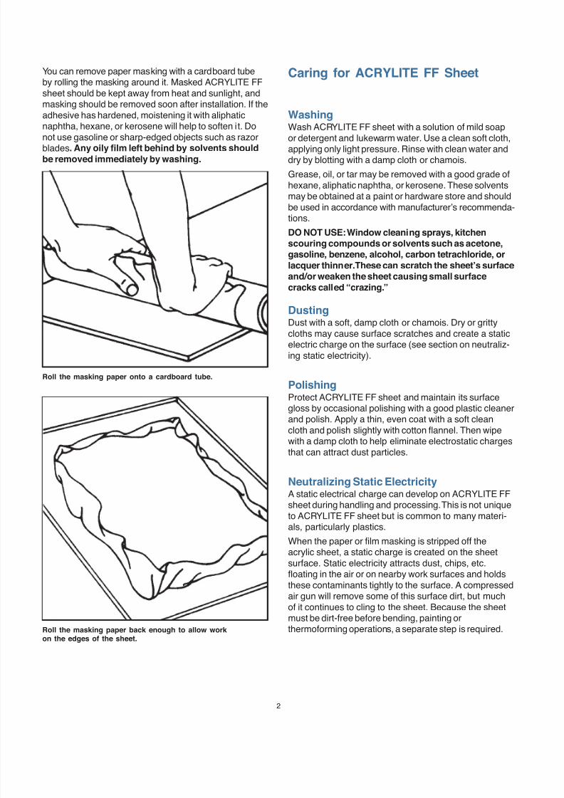
You can remove paper masking with a cardboard tubeby rolling the masking around it. Masked ACRYLITE FFsheet should be kept away from heat and sunlight, andmasking should be removed soon after installation. If theadhesive has hardened, moistening it with aliphaticnaphtha, hexane, or kerosene will help to soften it. Do
not use gasoline or sharp-edged objects such as razorblades. Any oily film left behind by solvents should
be removed immediately by washing.
Caring for ACRYLITE FF Sheet
WashingWash ACRYLITE FF sheet with a solution of mild soap
or detergent and lukewarm water. Use a clean soft cloth,applying only light pressure. Rinse with clean water anddry by blotting with a damp cloth or chamois.
Grease, oil, or tar may be removed with a good grade ofhexane, aliphatic naphtha, or kerosene. These solventsmay be obtained at a paint or hardware store and shouldbe used in accordance with manufacturer’s recommenda-tions.
DO NOT USE: Window cleaning sprays, kitchenscouring compounds or solvents such as acetone,gasoline, benzene, alcohol, carbon tetrachloride, or
lacquer thinner. These can scratch the sheet’s surface
and/or weaken the sheet causing small surfacecracks called “crazing.”
DustingDust with a soft, damp cloth or chamois. Dry or grittycloths may cause surface scratches and create a staticelectric charge on the surface (see section on neutraliz-ing static electricity).
PolishingProtect ACRYLITE FF sheet and maintain its surfacegloss by occasional polishing with a good plastic cleaner
and polish. Apply a thin, even coat with a soft cleancloth and polish slightly with cotton flannel. Then wipewith a damp cloth to help eliminate electrostatic chargesthat can attract dust particles.
Neutralizing Static ElectricityA static electrical charge can develop on ACRYLITE FFsheet during handling and processing. This is not uniqueto ACRYLITE FF sheet but is common to many materi-als, particularly plastics.
When the paper or film masking is stripped off theacrylic sheet, a static charge is created on the sheetsurface. Static electricity attracts dust, chips, etc.floating in the air or on nearby work surfaces and holdsthese contaminants tightly to the surface. A compressedair gun will remove some of this surface dirt, but muchof it continues to cling to the sheet. Because the sheetmust be dirt-free before bending, painting orthermoforming operations, a separate step is required.
Roll the masking paper onto a cardboard tube.
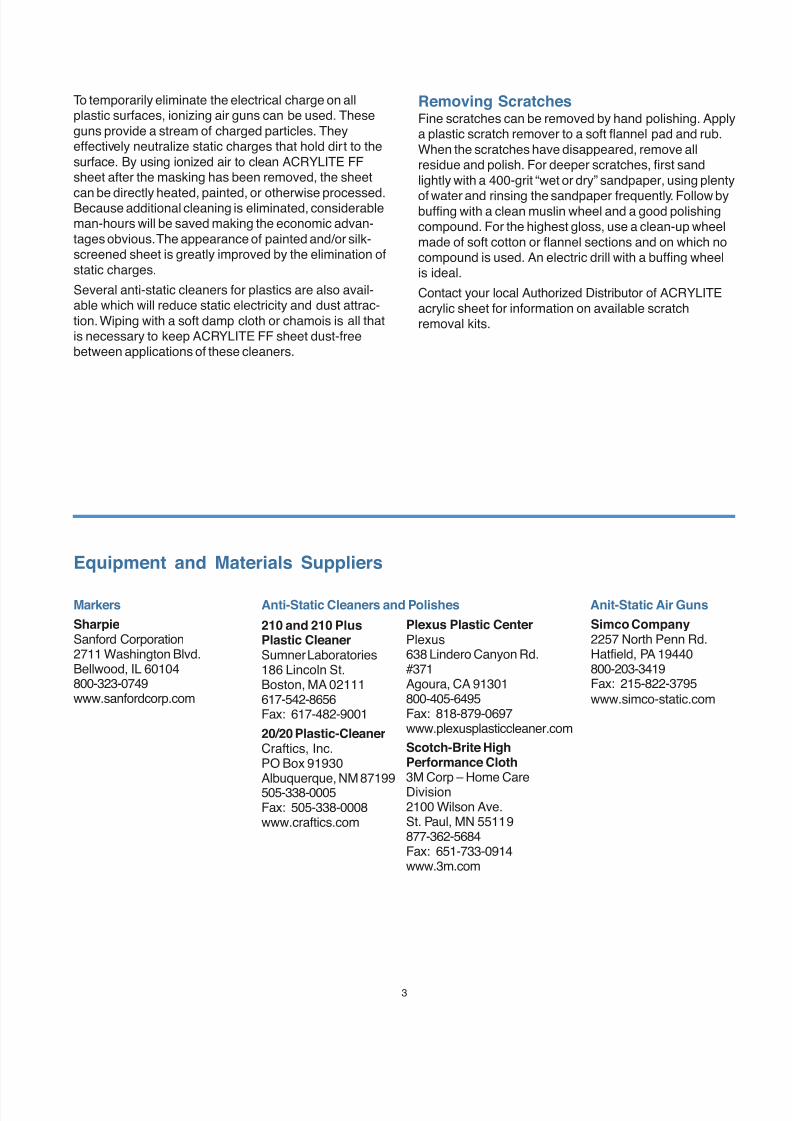
Roll the masking paper back enough to allow workon the edges of the sheet.
7/23/2019 Acrylite Fabrication Guide
http://slidepdf.com/reader/full/acrylite-fabrication-guide 3/663
To temporarily eliminate the electrical charge on allplastic surfaces, ionizing air guns can be used. Theseguns provide a stream of charged particles. Theyeffectively neutralize static charges that hold dirt to thesurface. By using ionized air to clean ACRYLITE FFsheet after the masking has been removed, the sheet
can be directly heated, painted, or otherwise processed.Because additional cleaning is eliminated, considerableman-hours will be saved making the economic advan-tages obvious. The appearance of painted and/or silk-screened sheet is greatly improved by the elimination ofstatic charges.
Several anti-static cleaners for plastics are also avail-able which will reduce static electricity and dust attrac-tion. Wiping with a soft damp cloth or chamois is all thatis necessary to keep ACRYLITE FF sheet dust-freebetween applications of these cleaners.
Removing ScratchesFine scratches can be removed by hand polishing. Applya plastic scratch remover to a soft flannel pad and rub.When the scratches have disappeared, remove allresidue and polish. For deeper scratches, first sandlightly with a 400-grit “wet or dry” sandpaper, using plenty
of water and rinsing the sandpaper frequently. Follow bybuffing with a clean muslin wheel and a good polishingcompound. For the highest gloss, use a clean-up wheelmade of soft cotton or flannel sections and on which nocompound is used. An electric drill with a buffing wheelis ideal.
Contact your local Authorized Distributor of ACRYLITEacrylic sheet for information on available scratchremoval kits.
Equipment and Materials Suppliers
Markers
SharpieSanford Corporation2711 Washington Blvd.Bellwood, IL 60104800-323-0749www.sanfordcorp.com
Anti-Static Cleaners and Polishes Anit-Static Air Guns
Simco Company2257 North Penn Rd.Hatfield, PA 19440800-203-3419Fax: 215-822-3795www.simco-static.com
Plexus Plastic CenterPlexus638 Lindero Canyon Rd.#371Agoura, CA 91301800-405-6495Fax: 818-879-0697www.plexusplasticcleaner.com
Scotch-Brite HighPerformance Cloth3M Corp – Home CareDivision2100 Wilson Ave.St. Paul, MN 55119877-362-5684Fax: 651-733-0914www.3m.com
210 and 210 PlusPlastic CleanerSumner Laboratories186 Lincoln St.Boston, MA 02111617-542-8656Fax: 617-482-9001
20/20 Plastic-CleanerCraftics, Inc.PO Box 91930Albuquerque, NM 87199505-338-0005Fax: 505-338-0008www.craftics.com
7/23/2019 Acrylite Fabrication Guide
http://slidepdf.com/reader/full/acrylite-fabrication-guide 4/664
1319(1J)-0803-10MG
© 2003 CYRO Industries. All rights reserved. Printed in USA.
Fire PrecautionsACRYLITE FF sheet is a combustible thermoplastic. Precautions should be taken to protect this material from flames and high heat sources. ACRYLITE FF sheetusually burns rapidly to completion if not extinguished. The products of combustion, if sufficient air is present, are carbon dioxide and water. However, in many firessufficient air will not be available and toxic carbon monoxide will be formed, as it will when other common combustible materials are burned. We urge good judgement inthe use of this versatile material and recommend that building codes be followed carefully to assure it is used properly.
CompatibilityLike other plastic materials, ACRYLITE FF sheet is subject to crazing, cracking or discoloration if brought into contact with incompatible materials. These materialsmay include cleaners, polishes, adhesives, sealants, gasketing or packaging materials, cutting emulsions, etc. See the Tech Briefs in this series for more information,or contact your ACRYLITE Sheet Distributor or the CYRO Technical Center for information on a specific product.
Important NoticeThe information and statements herein are believed to be reliable but are not to be construed as a warranty or representation for which we assume legal responsibility.Users should undertake sufficient verification and testing to determine the suitability for their own particular purpose of any information or products referred to herein.NO WARRANTY OF FITNESS FOR PARTICULAR PURPOSE IS MADE. Nothing herein is to be taken as permission, inducement or recommendation to practice anypatented invention without a license.
We invite you to visit our
TechKnowlogy Center at www.cyro.com.
Visitors have immediate access to frequently askedquestions, technical concerns, physical properties,processing conditions, fabrication tips,regulatory compliance information,engineering guidelines, tips fortroubleshooting, and hundredsof other facts about acrylics fromone of North America’sleading manufacturers ofacrylic-based polymer and
sheet products
Degussa, CYRO Industries379 Interpace ParkwayPO Box 677Parsippany, NJ 07054800-631-5384
SalesFor the name of a local Authorized Distributor,visit www.cyro.com or call 800-631-5384.
Additional Technical Information and Assistance
www.cyro.com
7/23/2019 Acrylite Fabrication Guide
http://slidepdf.com/reader/full/acrylite-fabrication-guide 5/661
Fabrication
TECH
BRIEF#2 Cutting with Circular Saws
This brief gives advice for:
Equipment
Procedures
Trouble Shooting Equipment Suppliers
Additional Technical Informationand Assistance
EquipmentACRYLITE® FF sheet is generally cut with overhead
panel saws, beam type panel saws, and table saws. Thesaws should have minimal vibration and be powerfulenough to make the required cuts.
Table saws with arbor sizes from 5/8” to 1” in diameterdriven by motors ranging from 3 – 10 hp are recom-mended. Direct drive or belt drive systems can be used.Most table saws provide a saw blade rotation speed of3,450 rpm.
Panel saws vary greatly in size from small vertical panelsaws for general purpose cutting to large CNC controlledhorizontal panel saws capable of high volume, tighttolerance cutting. Their drive motors should range in
power from 10 to 30 hp. Saw blade rotation speeds aretypically between 2,000 and 8,000 rpm. Panel saws withadjustable saw blade speed are available and providegreater flexibility for achieving an optimum saw cut.
In selecting a beam type table panel saw for cuttingacrylic sheet, the following three considerations arecritical.
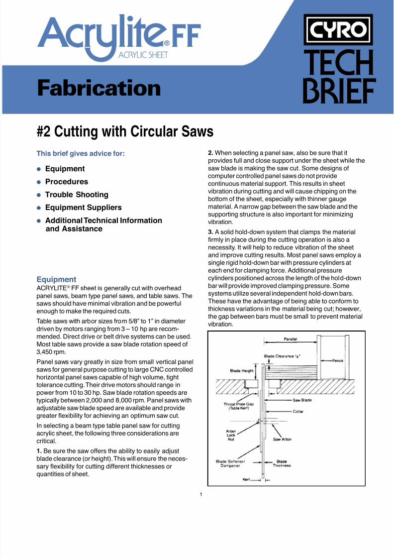
1. Be sure the saw offers the ability to easily adjustblade clearance (or height). This will ensure the neces-sary flexibility for cutting different thicknesses orquantities of sheet.
2. When selecting a panel saw, also be sure that itprovides full and close support under the sheet while thesaw blade is making the saw cut. Some designs ofcomputer controlled panel saws do not providecontinuous material support. This results in sheetvibration during cutting and will cause chipping on thebottom of the sheet, especially with thinner gaugematerial. A narrow gap between the saw blade and thesupporting structure is also important for minimizingvibration.
3. A solid hold-down system that clamps the materialfirmly in place during the cutting operation is also anecessity. It will help to reduce vibration of the sheetand improve cutting results. Most panel saws employ asingle rigid hold-down bar with pressure cylinders ateach end for clamping force. Additional pressurecylinders positioned across the length of the hold-downbar will provide improved clamping pressure. Some
systems utilize several independent hold-down bars.These have the advantage of being able to conform tothickness variations in the material being cut; however,the gap between bars must be small to prevent materialvibration.
7/23/2019 Acrylite Fabrication Guide
http://slidepdf.com/reader/full/acrylite-fabrication-guide 6/662
If using a table saw, be sure it comes equipped with allthe necessary safety devices. Most table saws comecomplete with a blade guard, splitter and anti-kick backdevice. Many anti-kick back devices do not work wellwith plastics. It may be necessary to consult theequipment manufacturer for help in selecting a suitabledevice. Kick-plate switches and electronic motor brakesshould also be considered for additional safety. As well,a heavy-duty fence will provide greater stability when
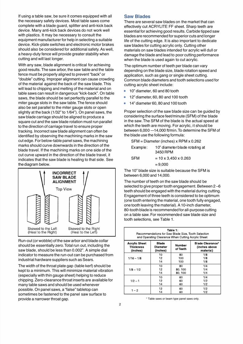
cutting and will last longer.With any saw, blade alignment is critical for achievinggood results. The saw arbor, the saw table and the tablefence must be properly aligned to prevent “back” or“double” cutting. Improper alignment can cause crowdingof the material against the back of the saw blade. Thiswill lead to chipping and melting of the material and ontable saws can result in dangerous “kick-back”. On tablesaws, the blade should be set perfectly parallel to themiter gauge slots in the saw table. The fence shouldalso be set parallel to the miter gauge slots or openslightly at the back (1/32” to 1/64”). On panel saws, thesaw blade carriage should be aligned to produce a
square cut and the saw blade rotation must run parallelto the direction of carriage travel to ensure propertracking. Incorrect saw blade alignment can often beidentified by observing the machining marks in the sawcut edge. For below-table panel saws, the machiningmarks should curve downwards in the direction of theblade travel. If the machining marks on one side of thecut curve upward in the direction of the blade travel, itindicates that the saw blade is healing to that side. Seethe diagram below.
Saw BladesThere are several saw blades on the market that caneffectively cut ACRYLITE FF sheet. Sharp teeth areessential for achieving good results. Carbide tipped sawblades are recommended for superior cuts and longerlife of the cutting edge. It is also important to dedicatesaw blades for cutting acrylic only. Cutting othermaterials on saw blades intended for acrylic will dull ordamage the blade and lead to poor cutting performance
when the blade is used again to cut acrylic.The optimum number of teeth per blade can varydepending on the blade size, blade rotation speed andapplication, such as gang or single sheet cutting.Common blade diameters and tooth selections used forcutting acrylic sheet include:
10” diameter, 60 and 80 tooth
12” diameter, 60, 80 and 100 tooth
14” diameter 60, 80 and 100 tooth
Proper selection of the saw blade size can be guided byconsidering the surface feet/minute (SFM) of the blade
in the saw. The SFM of the blade is the actual speed atwhich the teeth are moving. For acrylic, it should bebetween 6,000 -–14,000 ft/min. To determine the SFM ofthe blade use the following formula:
SFM = Diameter (inches) x RPM x 0.262
Example: 10” diameter blade rotating at3450 RPM
SFM = 10 x 3,450 x 0.263
= 9,000
The 10” blade size is suitable because the SFM isbetween 6,000 and 14,000.
The number of teeth on the saw blade should beselected to give proper tooth engagement. Between 2 –6teeth should be engaged with the material during cutting.Engagement of three teeth is considered to be optimum(one tooth entering the material, one tooth fully engaged,one tooth leaving the material). A 10-inch diameter,80-tooth blade is recommended for all-purpose cuttingon a table saw. For recommended saw blade size andtooth selections, see Table 1.
Run-out (or wobble) of the saw arbor and blade collarshould be essentially zero. Total run out, including thesaw blade, should be less than 0.002”. A simple dialindicator to measure the run-out can be purchased fromindustrial hardware suppliers such as Sears.
The width of the throat plate gap (table kerf) should bekept to a minimum. This will minimize material vibration(especially with thin gauge sheet) helping to reducechipping. Zero-clearance throat inserts are available formany table saws and should be used wheneverpossible. On panel saws, a “false” tabletop cansometimes be fastened to the panel saw surface toprovide a narrower throat gap. * Table saws or beam type panel saws only.
7/23/2019 Acrylite Fabrication Guide
http://slidepdf.com/reader/full/acrylite-fabrication-guide 7/663
For gang cutting of stacked sheets, a saw blade whoseteeth have increased radial clearance is recommended.This clearance will reduce carbide/plastic contact on thesides of the teeth and, therefore, reduce heat generatedby friction. Use ACRYLITE FF sheet masked withpolyethylene masking where possible when gang cutting;the polyethylene masking acts as a lubricant.
The quality of construction of the saw blade significantlyaffects how well it will cut. Quality considerations when
evaluating a saw blade include:
Run out, which should be less than 0.002”.
Teeth height, which needs to be nearly constant. Anyvariations must be gradual and not abrupt – the bladeshould have good concentricity.
Teeth positioning, which must all be in the sameradial plane, i.e. one tooth cannot extend to one sidemore than the others or chipping will result.
Blade plate quality, which should be tempered to ahardness of C42 – C46 giving it greater rigidity and
resulting in reduced vibration during operation.
Number of blade expansion slots, (4 – 5 for a 10”diameter blade) which minimize warping when theblade heats up.
Size of carbide tips. Larger tips mean the blade canbe sharpened more often. Tips will vary in size from5/32” – 13/32” long and 1/16” – 3/32” wide.
Brazing method used to attach the carbide tips to theplate. Carbide tips may be brazed to the plate byhand or by “machine induction”. Generally, “machine
induction” provides more consistent and reliableperformance.
Grinding quality or surface finish of the teeth, whichwill determine their sharpness and the quality of theresulting saw cut. Finer grinding will result in asmoother finish, leaving less machining marks on theteeth (visible under magnification) and cleaner,straighter tooth edges.
Saw blades should be handled carefully with cutresistant gloves. Avoid impact shocks such as droppingor hitting the saw blades, as the carbide tips are brittleand can chip easily. Also, impact shock can bend ablade, creating melting and chipping as it moves througha cut. When not in use, blades should be stored on aproperly designed wooden fixture that will protect theblade from accidental impacts and prevent accidentalcontact with its sharp tips.
Saw blades have a maximum rating for rotation speed.Be sure to verify that the saw being used will not exceedthe limitations of the saw blade that has been selected.Carbide tipped saw blades should never be operated inexcess of 18,000 SFM.
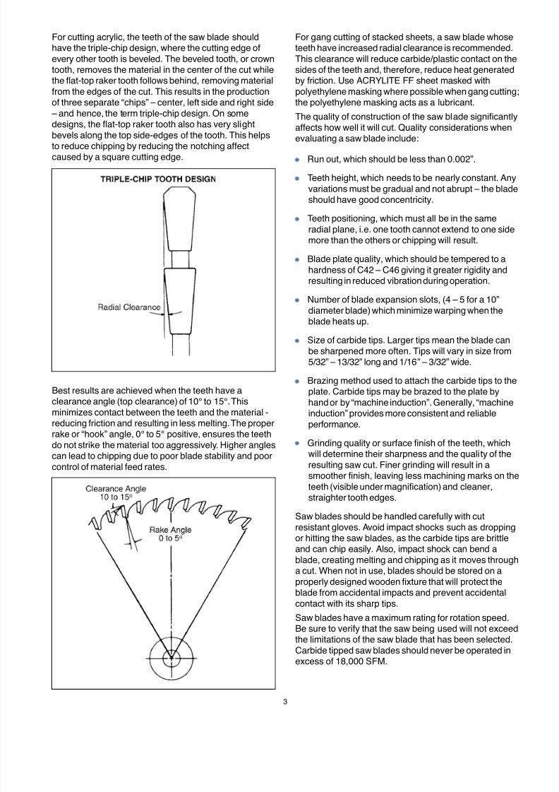
For cutting acrylic, the teeth of the saw blade shouldhave the triple-chip design, where the cutting edge ofevery other tooth is beveled. The beveled tooth, or crowntooth, removes the material in the center of the cut whilethe flat-top raker tooth follows behind, removing materialfrom the edges of the cut. This results in the productionof three separate “chips” – center, left side and right side
– and hence, the term triple-chip design. On somedesigns, the flat-top raker tooth also has very slight
bevels along the top side-edges of the tooth. This helpsto reduce chipping by reducing the notching affectcaused by a square cutting edge.
Best results are achieved when the teeth have aclearance angle (top clearance) of 10° to 15°. This
minimizes contact between the teeth and the material -reducing friction and resulting in less melting. The properrake or “hook” angle, 0° to 5° positive, ensures the teethdo not strike the material too aggressively. Higher anglescan lead to chipping due to poor blade stability and poorcontrol of material feed rates.
7/23/2019 Acrylite Fabrication Guide
http://slidepdf.com/reader/full/acrylite-fabrication-guide 8/664
Saw Blade Dampeners/StiffenersSaw blade dampeners or stiffeners can greatly reducesaw blade vibration during saw operation. They arehighly recommended for use when cutting acrylic sheetbecause they will usually result in improved saw cutquality and reduced noise during saw operation. (Note:Some high quality panel saws are built with large bladecollars and may not benefit from the use of a bladestiffener.) When installing a stiffener, be sure to remove
all foreign material from the saw blade and mountingwashers. Any bumps or scratch-burrs on the saw bladesurface should be stoned flat to ensure even metal-to-metal contact between the stiffener and the saw blade.Best results are normally obtained by selecting astiffener ½ to 2/3 the diameter of the saw blade.
CoolingThe use of a saw blade cooling system can yield amuch cleaner, smoother saw cut edge and greatlyincrease the life of the saw blade. These systemsremove heat from the blade and the plastic as it is being
cut. Two types of systems are commonly used.Compressed air or vortex tube cooled compressed airsystems are preferred. These systems are cleaner tooperate and require little maintenance. Mist systems,which apply a water-soluble oil with rust inhibitor, alsowork well providing blade lubrication as well as cooling.However, these systems will require more maintenanceand the material may need cleaning afterwards toremove residual oil. It is also important to ensure thatthe lubricating solution is compatible with acrylic. (Seethe Equipment and Material Suppliers section forrecommended lubricants or contact CYRO’s TechnicalService Department with compatibility questions.) When
using a saw blade cooling system, the air or mist streamshould be lightly sprayed on the teeth of the saw blade
just before they enter the material.
OperationFor table type saws or panel saws with the blademounted underneath, the blade should protrudeapproximately 1/8” to 1/2” above the work pieces. Theoptimum setting will vary with sheet thickness (seeTable 1). On overhead blade-mounted panel saws, theblade should protrude 1/32” through the material. Thesesettings should yield a smooth cut and minimize edgechipping by providing a favorable cutting angle for thecutting edge of the saw blade teeth. In general, largerblade clearances will reduce tooth engagement slightlyresulting in less heat generation and, in some situations,reduced melting while smaller blade clearances providebetter cutting and chip control resulting in less likelihoodof chipping on the bottom of the cut. Excessively lowblade clearances, often in combination with a dull blade,can cause chipping at the top of the cut.
Feed the material evenly through the saw. Uneven feedrates will produce melted spots or chipping on theplastic. Typical feed rates for ACRYLITE FF sheet are100” to 300” per minute. However, with some speciallydesigned saw blades (such as the “NO MELT” saw bladefrom Forrest Manufacturing Co.) feed rates as high as600” per minute can be used with success.
When cutting on a table saw, care must be taken toensure the operators safety. Always follow the
precautions outlined in the manual provided by the sawmanufacturer and consult the saw blade supplier forrecommendations on the proper use of their saw blades.
Safety precautions should also include (but are notlimited to) the following:
Always wear protective safety glasses with sideshields.
Ensure all guards are in place and operational.
Do not wear loose fitting clothing or jewelry and tieback long hair.
Ensure work area is clean and free of slip hazards.
Ensure the correct saw blade is mounted for thematerial being cut.
Ensure saw blade is in good condition, is properlymounted, rotates in the correct direction, is correctlyaligned, and is set at the proper height.
Never place hands within four (4) inches of therotating saw blade. If small pieces must be cut thatcould require the hands to be closer, then consideralternate methods of cutting, feeding or fixturing the
material for safer handling.
Never force-feed material into the blade. If the motorslows down, the material begins to “ride-up” or ifexcessive vibration is encountered, discontinuecutting and turn off the power.
Never position your body directly behind the sawblade during operation and be sure no one else isworking in the area behind the blade.
Never utilize the fence for sizing cuts less than 2.0times the length of exposed saw blade. For shortercuts use a miter gauge to guide the material.
Never use the miter gauge and fence together.
Never draw the material backwards during cutting.
Always hold the material firmly while feeding.
Stop the saw frequently to clean up cutoffs andsawdust. Be sure the saw blade has stoppedcompletely before cleaning. Do not attempt toremove waste while the saw is running.
7/23/2019 Acrylite Fabrication Guide
http://slidepdf.com/reader/full/acrylite-fabrication-guide 9/665
Trouble ShootingProblem Cause Solution
Chipping Sheet vibration On table saws, hold stacked sheet firmly while feeding. If gang cutting,hold sheets tightly together by clamping or taping them together.
On panel saws, ensure sheet is fully supported underneath and thatthe sheet is being firmly held down across the entire cut.
Chipping at bottom of cut: Reduce clearancethe clearance of the bladeabove the material is too large
Chipping at top of cut: the clearance Increase clearanceof the blade above the material is too small
Feed rate too fast Decrease feed rate
Incorrect blade style Use carbide tipped, triple chip design, saw blade
Incorrect blade size or number of teeth Use recommended blade size and tooth selection
Rake angle too high Rake should be 0° to + 5°
Excessive width of throat plate gap Replace throat plate
Blade vibration or wobble Clean collar and measure blade run out. Employ a blade stiffener.Replace blade with stiffer, higher quality blade.
Defective teeth (broken or out of alignment) Replace blade
SFM of blade is too low Increase RPM or blade size
Misalignment of blade or fence Verify that saw blade and fence are properly aligned
Melting Blade clearance too small Adjust clearance
Feed rate too slow Increase feed rate
Incorrect blade style Use carbide tipped, triple chip design, saw blade
Insufficient clearance behind cutting edge Clearance behind cutting edge of blade teeth
of blade teeth (top clearance) (top clearance) should be 10° to 15°
Insufficient radial clearance of blade teeth Use a blade with increased radial clearance on the teeth(kerf to blade plate clearance)
Dull blade Replace blade
Incorrect blade size or number of teeth Use recommended blade size and tooth selection
SFM of blade too high Reduce RPM or blade size
Misalignment of blade or fence Verify that saw blade and fence are properly aligned
General International
514-326-1161General Canada835 CherrierDrummondville QuebecCanada J2B 5A8819-472-1161Fax: 819-472-3266
Panel Saws
Plastisaw Systems2950 Bay Vista CourtBenecia, CA 94510707-746-5085
www.metlsaw.comSchelling America, Inc.301 Kitty Hawk DriveMorrisville, NC 27623919-544 0430Fax: 919-544-0920www.schelling.com
Giben America, Inc.3044 Northwoods CircleNorcross, GA 30071770-448-9140Fax: 770-448-9133www.giben.com
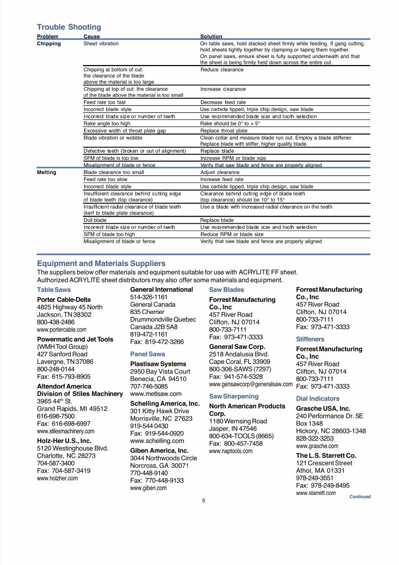
Equipment and Materials SuppliersThe suppliers below offer materials and equipment suitable for use with ACRYLITE FF sheet.Authorized ACRYLITE sheet distributors may also offer some materials and equipment.
Saw Blades
Forrest ManufacturingCo., Inc457 River RoadClifton, NJ 07014800-733-7111Fax: 973-471-3333
General Saw Corp.2518 Andalusia Blvd.Cape Coral, FL 33909800-306-SAWS (7297)Fax: [email protected]
Saw SharpeningNorth American ProductsCorp.1180 Wernsing RoadJasper, IN 47546800-634-TOOLS (8665)Fax: 800-457-7458www.naptools.com
Table Saws
Porter Cable-Delta4825 Highway 45 NorthJackson, TN 38302800-438-2486www.portercable.com
Powermatic and Jet Tools(WMH Tool Group)427 Sanford RoadLavergne, TN 37086800-248-0144Fax: 615-793-8905
Altendorf America
Division of Stiles Machinery3965 44th St.Grand Rapids, MI 49512616-698-7500Fax: 616-698-6997www.stilesmachinery.com
Holz-Her U.S., Inc.5120 Westinghouse Blvd.Charlotte, NC 28273704-587-3400Fax: 704-587-3419www.holzher.com
Forrest Manufacturing
Co., Inc457 River RoadClifton, NJ 07014800-733-7111Fax: 973-471-3333
Stiffeners
Forrest ManufacturingCo., Inc457 River RoadClifton, NJ 07014800-733-7111Fax: 973-471-3333
Dial Indicators
Grasche USA, Inc.240 Performance Dr. SEBox 1348Hickory, NC 28603-1348828-322-3253www.grasche.com
The L.S. Starrett Co.121 Crescent StreetAthol, MA 01331978-249-3551Fax: 978-249-8495
www.starrett.com Continued
7/23/2019 Acrylite Fabrication Guide
http://slidepdf.com/reader/full/acrylite-fabrication-guide 10/666
1319(2G)-0603-10MG
© 2003 CYRO Industries. All rights reserved. Printed in USA.
Fire PrecautionsACRYLITE FF sheet is a combustible thermoplastic. Precautions should be taken to protect this material from flames and high heat sources. ACRYLITE FF sheetusually burns rapidly to completion if not extinguished. The products of combustion, if sufficient air is present, are carbon dioxide and water. However, in many firessufficient air will not be available and toxic carbon monoxide will be formed, as it will when other common combustible materials are burned. We urge good judgement inthe use of this versatile material and recommend that building codes be followed carefully to assure it is used properly.
CompatibilityLike other plastic materials, ACRYLITE FF sheet is subject to crazing, cracking or discoloration if brought into contact with incompatible materials. These materialsmay include cleaners, polishes, adhesives, sealants, gasketing or packaging materials, cutting emulsions, etc. See the Tech Briefs in this series for more information,or contact your ACRYLITE Sheet Distributor or the CYRO Technical Center for information on a specific product.
Important NoticeThe information and statements herein are believed to be reliable but are not to be construed as a warranty or representation for which we assume legal responsibility.Users should undertake sufficient verification and testing to determine the suitability for their own particular purpose of any information or products referred to herein.NO WARRANTY OF FITNESS FOR PARTICULAR PURPOSE IS MADE. Nothing herein is to be taken as permission, inducement or recommendation to practice anypatented invention without a license.
We invite you to visit our
TechKnowlogy Center at www.cyro.com.
Visitors have immediate access to frequently askedquestions, technical concerns, physical properties,
processing conditions, fabrication tips,regulatory compliance information,engineering guidelines, tips fortroubleshooting, and hundredsof other facts about acrylics fromone of North America’sleading manufacturers ofacrylic-based polymer andsheet products.
Degussa / CYRO Industries379 Interpace ParkwayPO Box 677Parsippany, NJ 07054
800-631-5384
SalesFor the name of a local Authorized Distributor,visit www.cyro.com or call 800-631-5384.
.
Mist Systems
LSP Industries2511 – 20th StreetRockford, IL 61104815-226-8090Fax: [email protected]
Cooling Systems
Vortex TubesExair Corporation1250 Century Circle NorthCincinnati, OH 45246-3309513-671-3322Fax: 513- 671-3363www.exair.com
Equipment and Materials Suppliers
Lubricants
Oakite Fisan LC55Chemetall Oakite50 Valley RoadBerkeley Heights, NJ 07922800-526-4473908-464-4658www.oakitestore.com
Technical ServiceFor more information or specific questions about your project,
contact CYRO’s Technical Service Center.
Additional Technical Information and Assistance
www.cyro.com

7/23/2019 Acrylite Fabrication Guide
http://slidepdf.com/reader/full/acrylite-fabrication-guide 11/66
Fabrication
#4 Drilling
This brief gives advice for: Equipment
Procedures
Trouble Shooting
Equipment Suppliers
Additional Technical Informationand Assistance
TECH
BRIEF
Equipment
Drills
Any commercially available, power-driven equipment isacceptable. This includes portable drills, drill presses,lathes, automatic multiple-spindle drilling units, CNCrouters and machining centers.
Drill Bits
Several manufacturers offer drill bits designed especiallyfor plastics. Drill bits are commonly made of high-speedsteel (HSS), cobalt, HSS with carbide tips or solidcarbide. Metal-working high-speed steel twist drill bitscan be used with some modification .
Standard metal-working drill bits are designed toaggressively cut into metal as they are fed into it. Ifused on acrylic without modification, these bits will chipand cause other damage to the plastic. These drill bitsmust be reground in order to scrape the plastic insteadof sharply cutting into the material and gouging it. Thereare three points to consider when modifying a standardmetal-working twist drill for plastics.
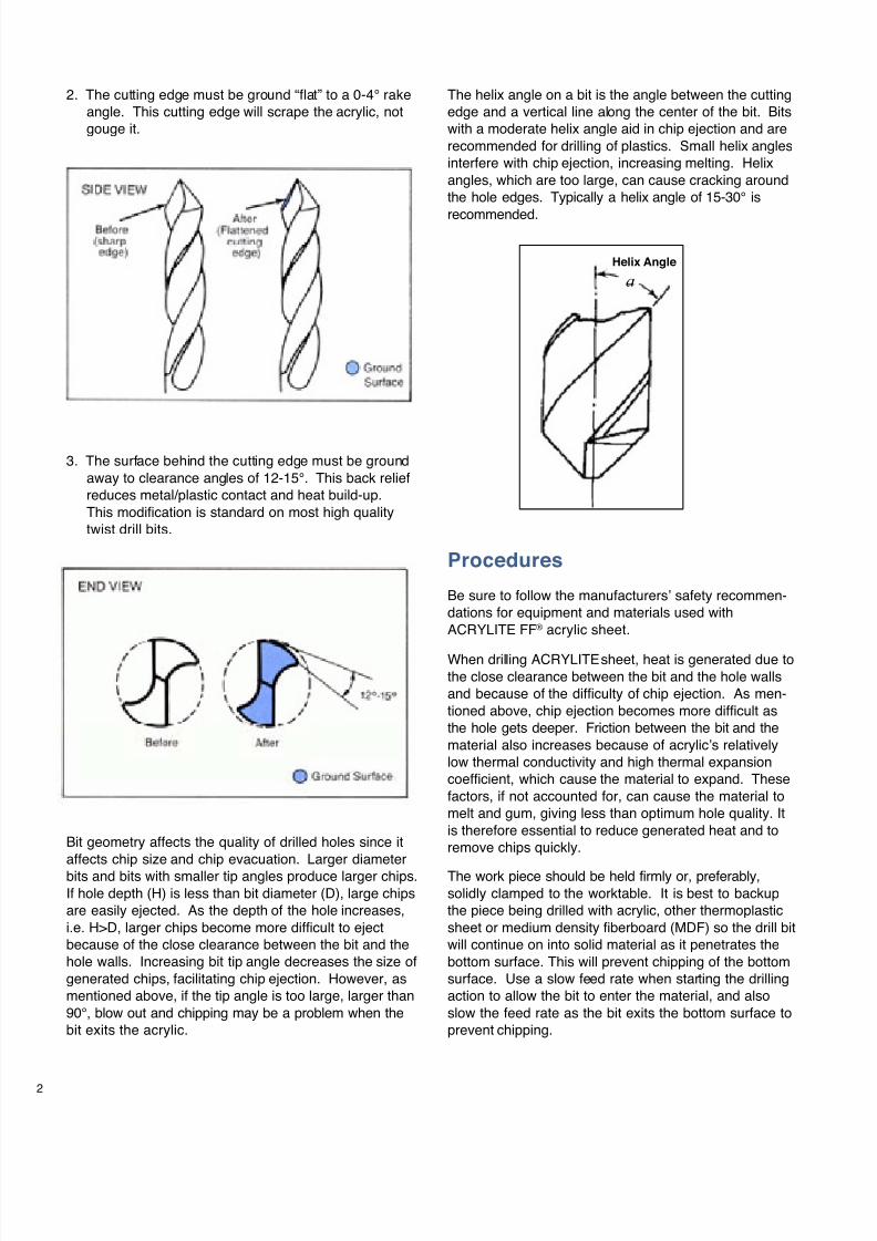
1. Tip angles on standard drill bits are commonly118°-130°. This point angle must be ground to60°-90°. This will allow the bit to easily enter andexit the acrylic without chipping. Larger tip anglescommonly cause cracking and blow out as the bitexits the sheet. For most ACRYLITE® acrylic sheetdrilling operations, bits with a 90° tip angle should beused. A bit with a 90° tip angle will generate smallerchips which are easier to evacuate, reducing meltingand improving hole quality. Care must be taken atthe points of entry and exit. Generally, bits with a
90° tip angle are recommended. Bits with 60° tipangles are also used, especially for holes withdiameters of1/2" and greater.
7/23/2019 Acrylite Fabrication Guide
http://slidepdf.com/reader/full/acrylite-fabrication-guide 12/66
2
Bit geometry affects the quality of drilled holes since itaffects chip size and chip evacuation. Larger diameterbits and bits with smaller tip angles produce larger chips.If hole depth (H) is less than bit diameter (D), large chipsare easily ejected. As the depth of the hole increases,i.e. H>D, larger chips become more difficult to ejectbecause of the close clearance between the bit and thehole walls. Increasing bit tip angle decreases the size ofgenerated chips, facilitating chip ejection. However, asmentioned above, if the tip angle is too large, larger than90°, blow out and chipping may be a problem when thebit exits the acrylic.
Procedures
Be sure to follow the manufacturers’ safety recommen-dations for equipment and materials used withACRYLITE FF® acrylic sheet.
When drilling ACRYLITEsheet, heat is generated due tothe close clearance between the bit and the hole wallsand because of the difficulty of chip ejection. As men-tioned above, chip ejection becomes more difficult asthe hole gets deeper. Friction between the bit and thematerial also increases because of acrylic’s relativelylow thermal conductivity and high thermal expansioncoefficient, which cause the material to expand. Thesefactors, if not accounted for, can cause the material tomelt and gum, giving less than optimum hole quality. Itis therefore essential to reduce generated heat and toremove chips quickly.
The work piece should be held firmly or, preferably,solidly clamped to the worktable. It is best to backupthe piece being drilled with acrylic, other thermoplasticsheet or medium density fiberboard (MDF) so the drill bitwill continue on into solid material as it penetrates thebottom surface. This will prevent chipping of the bottomsurface. Use a slow feed rate when starting the drillingaction to allow the bit to enter the material, and alsoslow the feed rate as the bit exits the bottom surface toprevent chipping.
3. The surface behind the cutting edge must be groundaway to clearance angles of 12-15°. This back reliefreduces metal/plastic contact and heat build-up.This modification is standard on most high qualitytwist drill bits.
a
Helix Angle
2. The cutting edge must be ground “flat” to a 0-4° rakeangle. This cutting edge will scrape the acrylic, notgouge it.
The helix angle on a bit is the angle between the cuttingedge and a vertical line along the center of the bit. Bitswith a moderate helix angle aid in chip ejection and arerecommended for drilling of plastics. Small helix anglesinterfere with chip ejection, increasing melting. Helixangles, which are too large, can cause cracking aroundthe hole edges. Typically a helix angle of 15-30° is
recommended.
7/23/2019 Acrylite Fabrication Guide
http://slidepdf.com/reader/full/acrylite-fabrication-guide 13/66
Table 1: Recommended values for SFM and IPR
Diameter of bit (in.) SFM IPR
1/16 20-160 0.001
1/8 20-160 0.002
1/4 20-160 0.004
3/8 20-160 0.006
1/2 30-90 0.008
3/4 30-90 0.010
≥1 30-90 0.012-0.015
These recommended values can be used with the above equations to determine drilling settings.Alternatively, figures 1, 2, and 3 provided below and on the next page can be used.
For drilling acrylic the recommended values for SFM and IPR are given in Table 1 below.
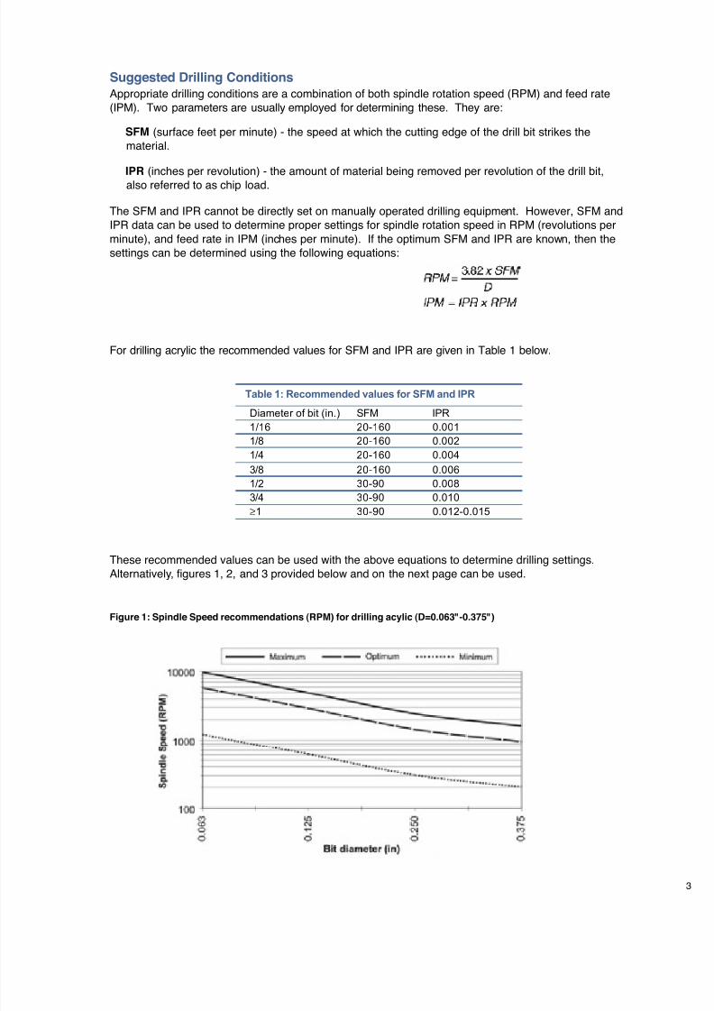
Figure 1: Spindle Speed recommendations (RPM) for drilling acylic (D=0.063"-0.375")
Suggested Drilling Conditions
Appropriate drilling conditions are a combination of both spindle rotation speed (RPM) and feed rate(IPM). Two parameters are usually employed for determining these. They are:
SFM (surface feet per minute) - the speed at which the cutting edge of the drill bit strikes thematerial.
IPR (inches per revolution) - the amount of material being removed per revolution of the drill bit,also referred to as chip load.
The SFM and IPR cannot be directly set on manually operated drilling equipment. However, SFM andIPR data can be used to determine proper settings for spindle rotation speed in RPM (revolutions perminute), and feed rate in IPM (inches per minute). If the optimum SFM and IPR are known, then thesettings can be determined using the following equations:
7/23/2019 Acrylite Fabrication Guide
http://slidepdf.com/reader/full/acrylite-fabrication-guide 14/66
4
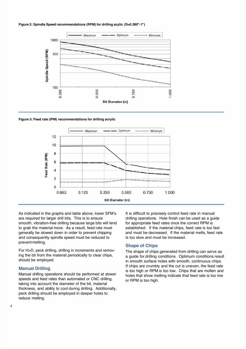
As indicated in the graphs and table above, lower SFM’sare required for larger drill bits. This is to ensuresmooth, vibration-free drilling because large bits will tendto grab the material more. As a result, feed rate mustgenerally be slowed down in order to prevent chippingand consequently spindle speed must be reduced toprevent melting.
For H>D, peck drilling, drilling in increments and remov-ing the bit from the material periodically to clear chips,should be employed.
Manual Drilling
Manual drilling operations should be performed at slowerspeeds and feed rates than automated or CNC drilling,taking into account the diameter of the bit, materialthickness, and ability to cool during drilling. Additionally,peck drilling should be employed in deeper holes toreduce melting.
It is difficult to precisely control feed rate in manualdrilling operations. Hole finish can be used as a guidefor appropriate feed rates once the correct RPM isestablished. If the material chips, feed rate is too fastand must be decreased. If the material melts, feed rateis too slow and must be increased.
Shape of ChipsThe shape of chips generated from drilling can serve asa guide for drilling conditions. Optimum conditions resultin smooth surface holes with smooth, continuous chips.If chips are crumbly and the cut is uneven, the feed rateis too high or RPM is too low. Chips that are molten andholes that show melting indicate that feed rate is too lowor RPM is too high.
Figure 2: Spindle Speed recommendations (RPM) for drilling acylic (D=0.380"-1")
Figure 3: Feed rate (IPM) recommendations for drilling acrylic
7/23/2019 Acrylite Fabrication Guide
http://slidepdf.com/reader/full/acrylite-fabrication-guide 15/66
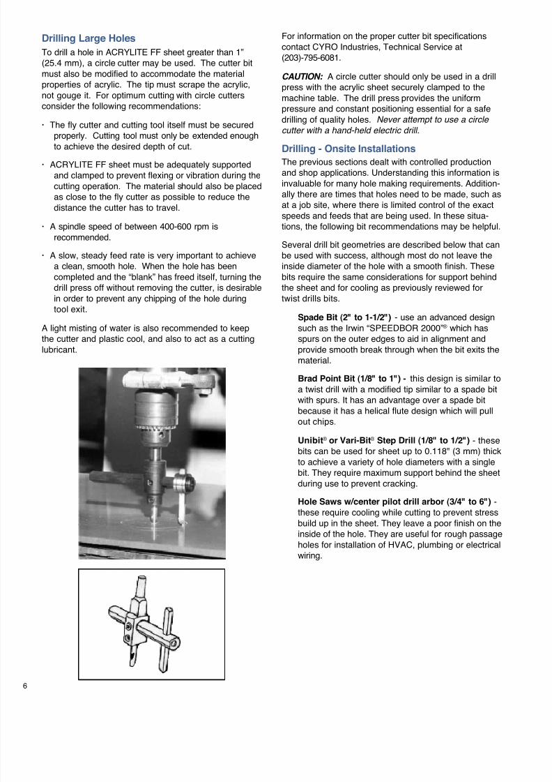
Circuit Board Drilling
Circuit board drilling is a specialcase where automated machinesdrill thousands of tiny holes at veryhigh speed. Specially designed bitsare required. Feed rate and RPMrecommendations are provided in
figures 4 and 5.
Figure 4: Spindle speed (RPM) recommendations for acrylic circuit board drilling
Figure 5: Feed rate (IPM) recommendations for acrylic circuit board drilling
Coolants
Air or liquid coolants should be used whenever possible.Coolants reduce generated heat, and therefore improvehole quality. In certain hole depths and sizes, coolantsare necessary to prevent melting. As a general rule,coolants should be used when the depth of the hole (H)exceeds bit diameter (D) (e.g. for D=0.250", a coolant
should be used for H>0.250"). Coolants should also beused for holes greater than or equal to 1/2" in diameter(D≥ 1/2").
Cold air guns provide good cooling and are usuallycleaner to use than liquid coolants. However, liquidcoolants provide more cooling, as the liquid can trickledown the hole as the bit goes through the material,resulting in better hole finishes. Water, kerosene,mineral oils and other compatible solvents can beused.
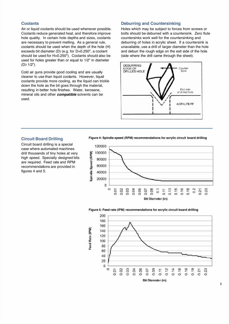
Deburring and Countersinking
Holes which may be subject to forces from screws orbolts should be deburred with a countersink. Zero flutecountersinks work well for the countersinking anddeburring of holes in acrylic sheet. If a countersink isunavailable, use a drill of larger diameter than the holeand deburr the rough edge on the exit side of the hole
(side where the drill came through the sheet).
7/23/2019 Acrylite Fabrication Guide
http://slidepdf.com/reader/full/acrylite-fabrication-guide 16/66
6
Drilling Large Holes
To drill a hole in ACRYLITE FF sheet greater than 1”(25.4 mm), a circle cutter may be used. The cutter bitmust also be modified to accommodate the materialproperties of acrylic. The tip must scrape the acrylic,not gouge it. For optimum cutting with circle cuttersconsider the following recommendations:
· The fly cutter and cutting tool itself must be secured
properly. Cutting tool must only be extended enoughto achieve the desired depth of cut.
· ACRYLITE FF sheet must be adequately supportedand clamped to prevent flexing or vibration during thecutting operation. The material should also be placedas close to the fly cutter as possible to reduce thedistance the cutter has to travel.
· A spindle speed of between 400-600 rpm isrecommended.
· A slow, steady feed rate is very important to achievea clean, smooth hole. When the hole has been
completed and the “blank” has freed itself, turning thedrill press off without removing the cutter, is desirablein order to prevent any chipping of the hole duringtool exit.
A light misting of water is also recommended to keepthe cutter and plastic cool, and also to act as a cuttinglubricant.
For information on the proper cutter bit specificationscontact CYRO Industries, Technical Service at(203)-795-6081.
CAUTION: A circle cutter should only be used in a drillpress with the acrylic sheet securely clamped to themachine table. The drill press provides the uniformpressure and constant positioning essential for a safedrilling of quality holes. Never attempt to use a circle
cutter with a hand-held electric drill.
Drilling - Onsite Installations
The previous sections dealt with controlled productionand shop applications. Understanding this information isinvaluable for many hole making requirements. Addition-ally there are times that holes need to be made, such asat a job site, where there is limited control of the exactspeeds and feeds that are being used. In these situa-tions, the following bit recommendations may be helpful.
Several drill bit geometries are described below that canbe used with success, although most do not leave theinside diameter of the hole with a smooth finish. These
bits require the same considerations for support behindthe sheet and for cooling as previously reviewed fortwist drills bits.
Spade Bit (2" to 1-1/2") - use an advanced designsuch as the Irwin “SPEEDBOR 2000”® which hasspurs on the outer edges to aid in alignment andprovide smooth break through when the bit exits thematerial.
Brad Point Bit (1/8" to 1") - this design is similar toa twist drill with a modified tip similar to a spade bitwith spurs. It has an advantage over a spade bit
because it has a helical flute design which will pullout chips.
Unibit® or Vari-Bit® Step Drill (1/8" to 1/2") - thesebits can be used for sheet up to 0.118" (3 mm) thickto achieve a variety of hole diameters with a singlebit. They require maximum support behind the sheetduring use to prevent cracking.
Hole Saws w/center pilot drill arbor (3/4" to 6") -these require cooling while cutting to prevent stressbuild up in the sheet. They leave a poor finish on theinside of the hole. They are useful for rough passage
holes for installation of HVAC, plumbing or electricalwiring.
7/23/2019 Acrylite Fabrication Guide
http://slidepdf.com/reader/full/acrylite-fabrication-guide 17/66
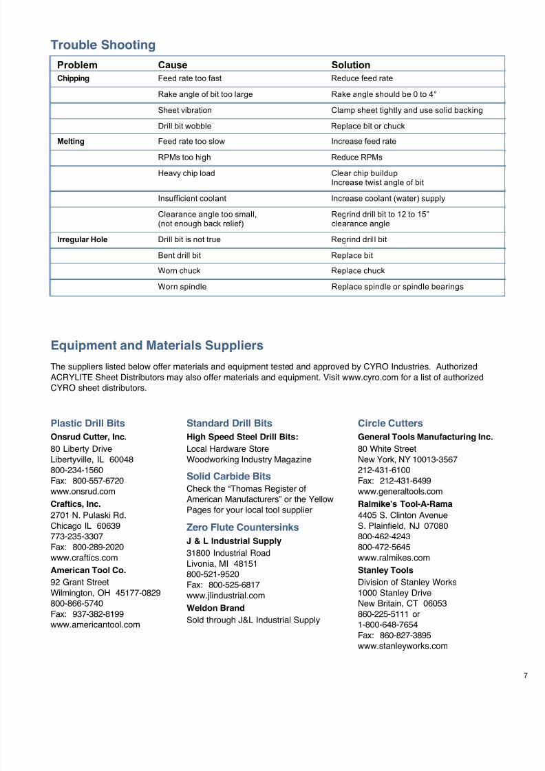
Trouble Shooting
Problem Cause Solution
Chipping Feed rate too fast Reduce feed rate
Rake angle of bit too large Rake angle should be 0 to 4°
Sheet vibration Clamp sheet tightly and use solid backing
Drill bit wobble Replace bit or chuck
Melting Feed rate too slow Increase feed rate
RPMs too high Reduce RPMs
Heavy chip load Clear chip buildupIncrease twist angle of bit
Insufficient coolant Increase coolant (water) supply
Clearance angle too small, Regrind drill bit to 12 to 15°(not enough back relief) clearance angle
Irregular Hole Drill bit is not true Regrind drill bit
Bent drill bit Replace bit
Worn chuck Replace chuck
Worn spindle Replace spindle or spindle bearings
Equipment and Materials Suppliers
The suppliers listed below offer materials and equipment tested and approved by CYRO Industries. AuthorizedACRYLITE Sheet Distributors may also offer materials and equipment. Visit www.cyro.com for a list of authorizedCYRO sheet distributors.
Circle Cutters
General Tools Manufacturing Inc.
80 White StreetNew York, NY 10013-3567212-431-6100Fax: 212-431-6499www.generaltools.com
Ralmike’s Tool-A-Rama
4405 S. Clinton AvenueS. Plainfield, NJ 07080
800-462-4243800-472-5645www.ralmikes.com
Stanley Tools
Division of Stanley Works1000 Stanley DriveNew Britain, CT 06053860-225-5111 or1-800-648-7654Fax: 860-827-3895www.stanleyworks.com
Standard Drill Bits
High Speed Steel Drill Bits:
Local Hardware StoreWoodworking Industry Magazine
Solid Carbide BitsCheck the “Thomas Register ofAmerican Manufacturers” or the YellowPages for your local tool supplier
Zero Flute Countersinks
J & L Industrial Supply31800 Industrial RoadLivonia, MI 48151800-521-9520Fax: 800-525-6817www.jlindustrial.com
Weldon Brand
Sold through J&L Industrial Supply
Plastic Drill Bits
Onsrud Cutter, Inc.
80 Liberty DriveLibertyville, IL 60048800-234-1560Fax: 800-557-6720www.onsrud.com
Craftics, Inc.
2701 N. Pulaski Rd.Chicago IL 60639
773-235-3307Fax: 800-289-2020www.craftics.com
American Tool Co.
92 Grant StreetWilmington, OH 45177-0829800-866-5740Fax: 937-382-8199www.americantool.com
7/23/2019 Acrylite Fabrication Guide
http://slidepdf.com/reader/full/acrylite-fabrication-guide 18/66
8 1319(4E)-1001-5RA © 2001 CYRO Industries. All Rights Reserved. Printed in USA.
Additional Technical Informationand AssistanceWe invite you to visit our TechKnowlogy Center
on www.cyro.com.
Visitors have immediate access to frequently asked
questions, technical concerns, physical properties,processing conditions, fabrication tips, regulatorycompliance information, engineering guidelines, tipsfor troubleshooting, and hundreds of other facts aboutacrylics from one of North America’s leadingmanufacturers of acrylic-basedpolymer and sheet products.
Fire Precautions
ACRYLITE FF sheet is a combustible thermoplastic. Precautions should be
taken to protect this material from flames and high heat sources. ACRYLITE FFsheet usually burns rapidly to completion if not extinguished. The products ofcombustion, if sufficient air is present, are carbon dioxide and water. However,
in many fires sufficient air will not be available and toxic carbon monoxide willbe formed, as it will when other common combustible materials are burned. Weurge good judgement in the use of this versatile material and recommend thatbuilding codes be followed carefully to assure it is used properly.
Compatibility
Like other plastic materials, ACRYLITE FF sheet is subject to crazing, cracking
or discoloration if brought into contact with incompatible materials. Thesematerials may include cleaners, polishes, adhesives, sealants, gasketing orpackaging materials, cutting emulsions, etc. See the Tech Briefs in this seriesfor more information, or contact your ACRYLITE Sheet Distributor or the CYROTechnical Center for information on a specific product.
Important Notice:
The information and statements herein are believed to be reliable but are not tobe construed as a warranty or representation for which we assume legalresponsibility. Users should undertake sufficient verification and testing to
determine the suitability for their own particular purpose of any information orproducts referred to herein. NO WARRANTY OF FITNESS FOR PARTICULARPURPOSE IS MADE. Nothing herein is to be taken as permission, inducementor recommendation to practice any patented invention without a license.
Sales Offices
For the name of your local Authorized Distributor,
call 800-631-5384, visit www.cyro.com, or contactthe nearest regional sales office:
Eastern Region
100 Enterpise DrivePO Box 5055Rockaway, NJ 07866973-442-6130
South/Central Region
101 East Park Blvd.Suite 1039Plano, TX 75074
972-424-6830
Western Region
3180 Crow Canyon PlaceSuite 240San Ramon, CA 94583925-866-9300
CYRO Canada Inc.
6285 Northam DriveSuite 100Mississauga,
Ontario L4V 1X5905-677-1388800-268-4743
Technical Service
For more information or specific questions about
your project, contact CYRO’s Technical ServiceRepresentatives.
CYRO Industries
25 Executive Blvd.Orange, CT 06477203-795-6081
CYRO Canada Inc.
6285 Northam DriveSuite 100Mississauga,Ontario L4V 1X5905-677-1388800-268-4743
Web site: www.cyro.com
For additional information contact:
Degussa, CYRO Industries
379 Interpace Parkway,
PO Box 677, Parsippany, NJ 07054-0677
800-631-5384
www.cyro.com
www.degussa.com
CYRO Industries is a wholly-owned subsidiary of Degussa.
7/23/2019 Acrylite Fabrication Guide
http://slidepdf.com/reader/full/acrylite-fabrication-guide 19/66
Fabrication
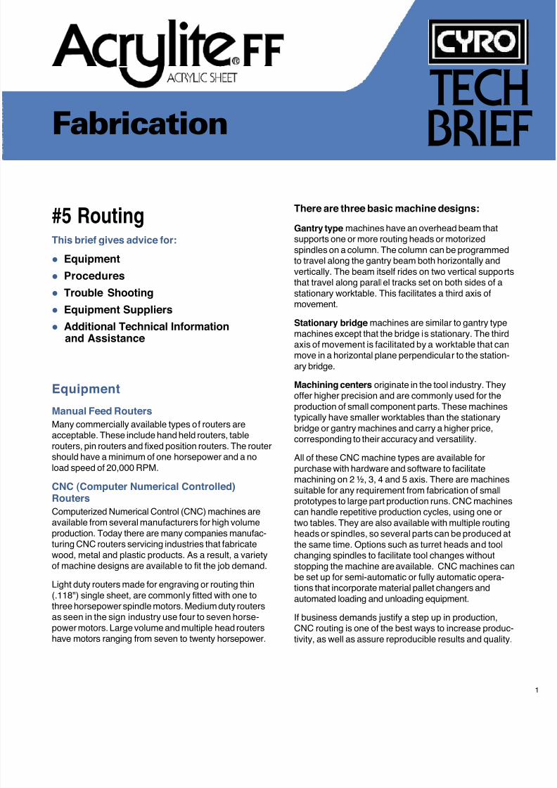
#5 RoutingThis brief gives advice for:
Equipment
Procedures Trouble Shooting
Equipment Suppliers
Additional Technical Informationand Assistance
TECH
BRIEF
Equipment
Manual Feed RoutersMany commercially available types of routers areacceptable. These include hand held routers, tablerouters, pin routers and fixed position routers. The routershould have a minimum of one horsepower and a noload speed of 20,000 RPM.
CNC (Computer Numerical Controlled)Routers
Computerized Numerical Control (CNC) machines areavailable from several manufacturers for high volumeproduction. Today there are many companies manufac-turing CNC routers servicing industries that fabricate
wood, metal and plastic products. As a result, a varietyof machine designs are available to fit the job demand.
Light duty routers made for engraving or routing thin(.118") single sheet, are commonly fitted with one tothree horsepower spindle motors. Medium duty routersas seen in the sign industry use four to seven horse-power motors. Large volume and multiple head routershave motors ranging from seven to twenty horsepower.
There are three basic machine designs:
Gantry type machines have an overhead beam thatsupports one or more routing heads or motorizedspindles on a column. The column can be programmedto travel along the gantry beam both horizontally and
vertically. The beam itself rides on two vertical supportsthat travel along parallel tracks set on both sides of astationary worktable. This facilitates a third axis ofmovement.
Stationary bridge machines are similar to gantry typemachines except that the bridge is stationary. The thirdaxis of movement is facilitated by a worktable that canmove in a horizontal plane perpendicular to the station-ary bridge.
Machining centers originate in the tool industry. Theyoffer higher precision and are commonly used for theproduction of small component parts. These machines
typically have smaller worktables than the stationarybridge or gantry machines and carry a higher price,corresponding to their accuracy and versatility.
All of these CNC machine types are available forpurchase with hardware and software to facilitatemachining on 2 ½, 3, 4 and 5 axis. There are machinessuitable for any requirement from fabrication of smallprototypes to large part production runs. CNC machinescan handle repetitive production cycles, using one ortwo tables. They are also available with multiple routingheads or spindles, so several parts can be produced atthe same time. Options such as turret heads and tool
changing spindles to facilitate tool changes withoutstopping the machine are available. CNC machines canbe set up for semi-automatic or fully automatic opera-tions that incorporate material pallet changers andautomated loading and unloading equipment.
If business demands justify a step up in production,CNC routing is one of the best ways to increase produc-tivity, as well as assure reproducible results and quality.
7/23/2019 Acrylite Fabrication Guide
http://slidepdf.com/reader/full/acrylite-fabrication-guide 20/66
2
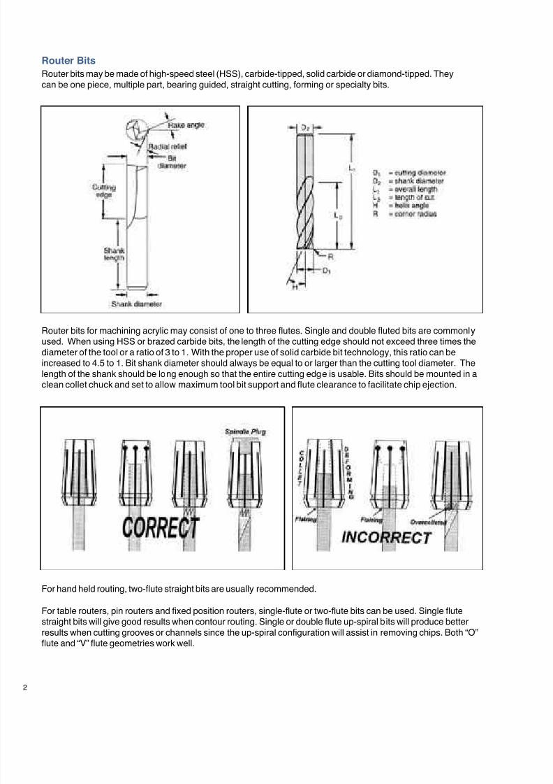
Router Bits
Router bits may be made of high-speed steel (HSS), carbide-tipped, solid carbide or diamond-tipped. Theycan be one piece, multiple part, bearing guided, straight cutting, forming or specialty bits.
Router bits for machining acrylic may consist of one to three flutes. Single and double fluted bits are commonlyused. When using HSS or brazed carbide bits, the length of the cutting edge should not exceed three times thediameter of the tool or a ratio of 3 to 1. With the proper use of solid carbide bit technology, this ratio can beincreased to 4.5 to 1. Bit shank diameter should always be equal to or larger than the cutting tool diameter. Thelength of the shank should be long enough so that the entire cutting edge is usable. Bits should be mounted in aclean collet chuck and set to allow maximum tool bit support and flute clearance to facilitate chip ejection.
For table routers, pin routers and fixed position routers, single-flute or two-flute bits can be used. Single flutestraight bits will give good results when contour routing. Single or double flute up-spiral bits will produce betterresults when cutting grooves or channels since the up-spiral configuration will assist in removing chips. Both “O”flute and “V” flute geometries work well.
For hand held routing, two-flute straight bits are usually recommended.
7/23/2019 Acrylite Fabrication Guide
http://slidepdf.com/reader/full/acrylite-fabrication-guide 21/66
When processing acrylic using a CNC router, solidcarbide, up-spiral “O” flute router bits will produce thebest results. They are available with one, two or threeflutes. Common bit sizes are 1/8" to 1/2" diameter.These bits are less susceptible to friction and heat buildup because the O-flute design allows chips to curlnaturally as they are formed and facilitates better
evacuation of the chips from the cutting area. In lessdemanding applications, standard twist bits (V-flutegeometry) can also be used with success.
In general, up-spiral bits are recommended becausethey pull chips up and out of the way, reducing frictionalheat build-up. However, when material hold down is anissue, straight flute or down-spiral geometries may bebeneficial. Increasing the number of flutes on the bit willusually result in a better quality finish on the edges ofthe routed surface. However, tooling cost also increaseswith the number of flutes on the bit. Therefore, it is bestto start with a one or two flute bit and only step up to a
higher number of flutes if necessary.
Tools with a single flat-faced cutter are commonlyemployed for engraving applications. These includeprofile cutters, parallel cutters and braille cutters.Rigidity is important so solid carbide tools should beused. When engraving letter widths greater than 0.060",other router bit types may be necessary to provide thedesired finish on the inside of the letter. These include V-grooving, veining, up-spiral ball nose and double-edgebottom surfacing bits.
Tool Maintenance
The cutters should be kept sharp. Chipping or overheat-ing will occur with a dull cutter. Both will impart stressinto the sheet.
Procedures
Be sure to follow the manufacturers’ safety recommen-dations for equipment and materials used withACRYLITE® FF acrylic sheet.
Safety
When using routing equipment always wear protectiveface shields or safety goggles. Hearing protection isrecommended for extended periods of routing. If avacuum system is not used, a respirator or dust maskwill offer protection from dust particles.
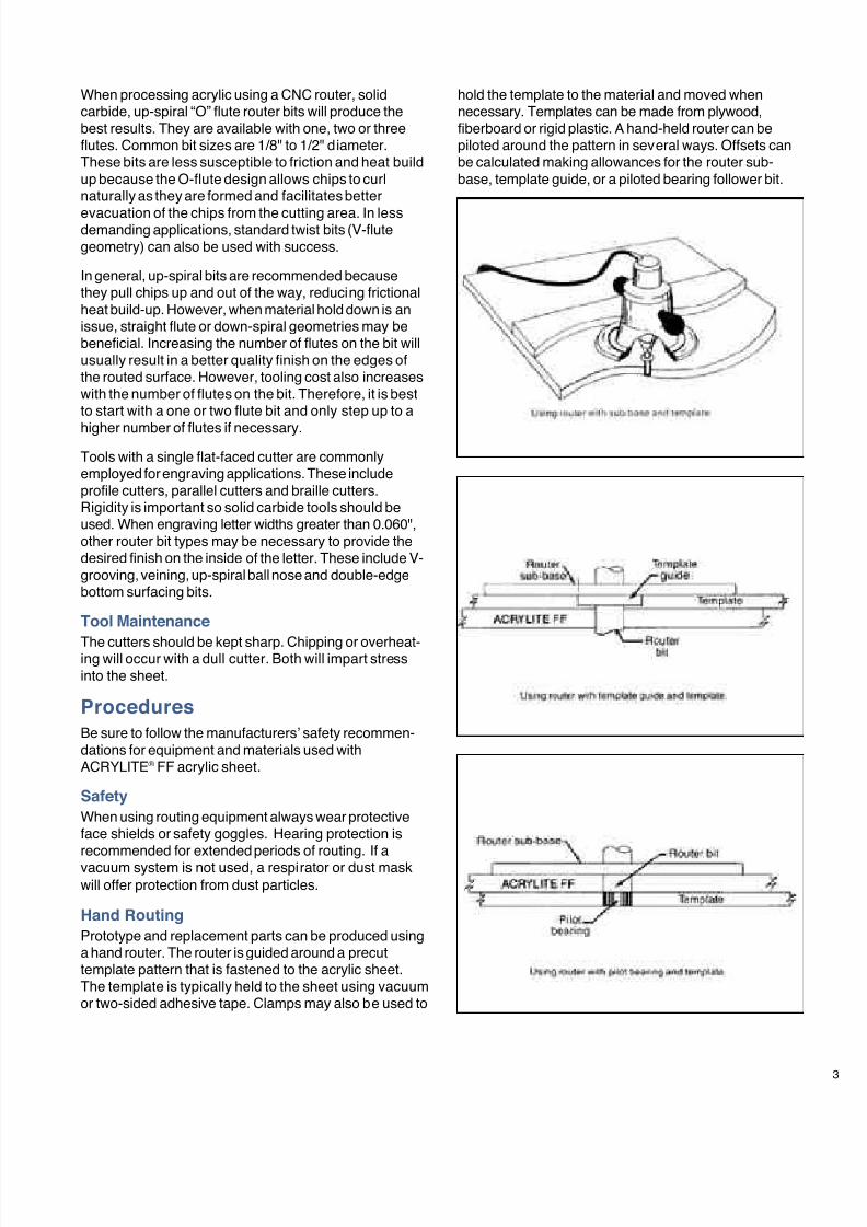
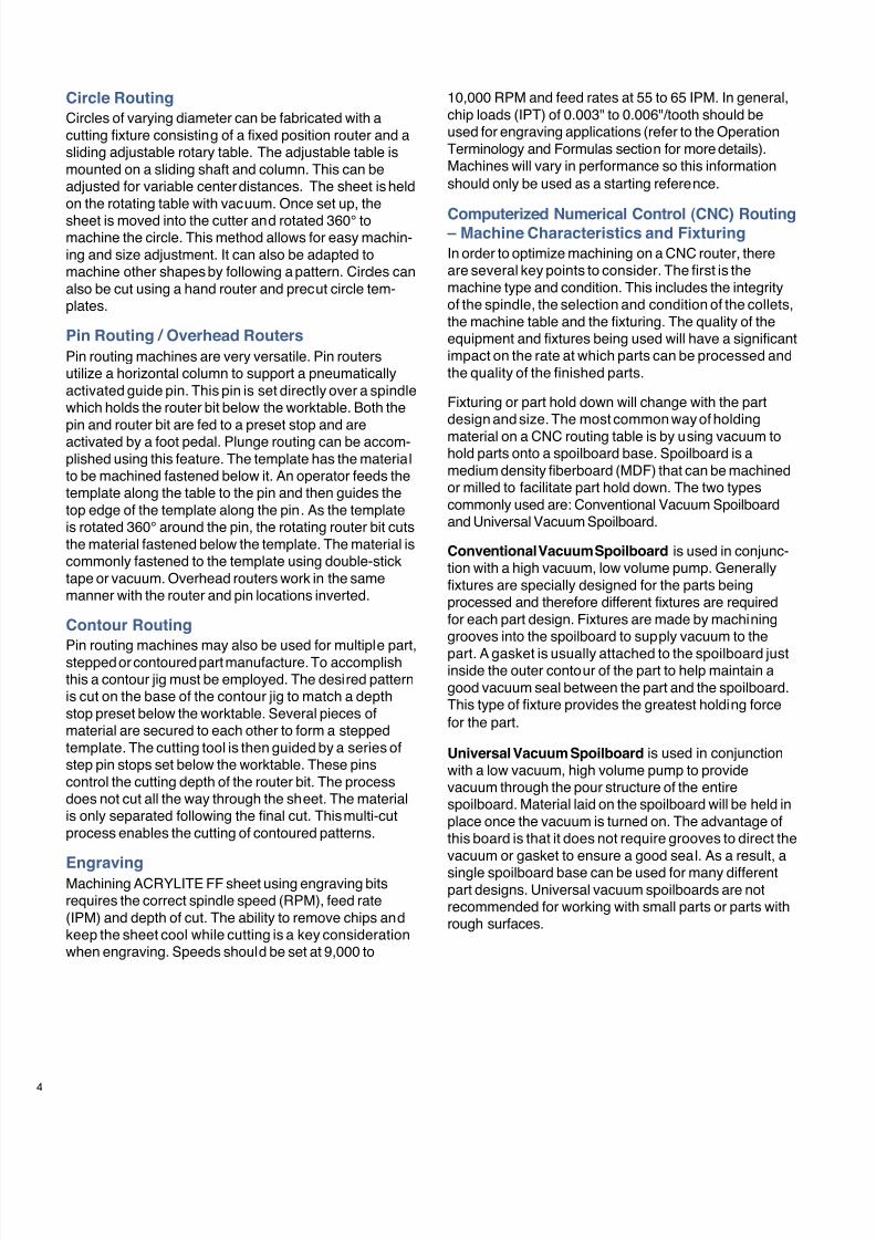
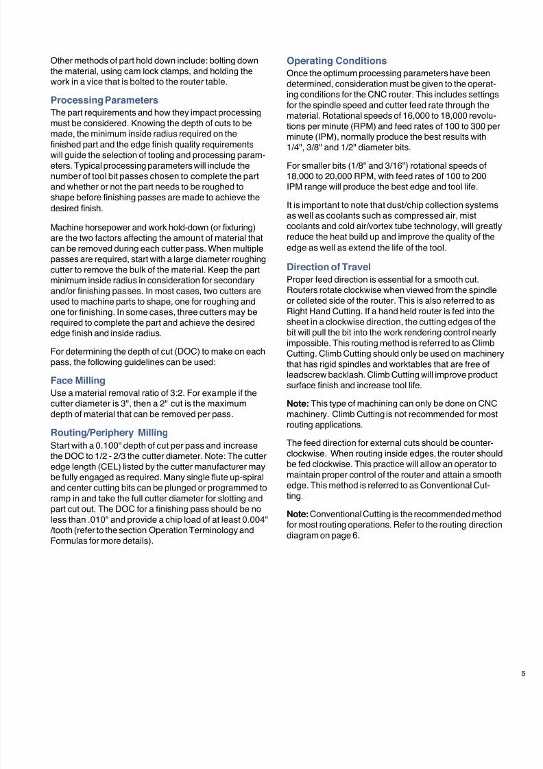
Hand Routing
Prototype and replacement parts can be produced usinga hand router. The router is guided around a precuttemplate pattern that is fastened to the acrylic sheet.The template is typically held to the sheet using vacuumor two-sided adhesive tape. Clamps may also be used to
hold the template to the material and moved whennecessary. Templates can be made from plywood,fiberboard or rigid plastic. A hand-held router can bepiloted around the pattern in several ways. Offsets canbe calculated making allowances for the router sub-base, template guide, or a piloted bearing follower bit.
7/23/2019 Acrylite Fabrication Guide
http://slidepdf.com/reader/full/acrylite-fabrication-guide 22/66
4
Circle Routing
Circles of varying diameter can be fabricated with acutting fixture consisting of a fixed position router and asliding adjustable rotary table. The adjustable table ismounted on a sliding shaft and column. This can beadjusted for variable center distances. The sheet is heldon the rotating table with vacuum. Once set up, the
sheet is moved into the cutter and rotated 360° tomachine the circle. This method allows for easy machin-ing and size adjustment. It can also be adapted tomachine other shapes by following a pattern. Circles canalso be cut using a hand router and precut circle tem-plates.
Pin Routing / Overhead Routers
Pin routing machines are very versatile. Pin routersutilize a horizontal column to support a pneumaticallyactivated guide pin. This pin is set directly over a spindlewhich holds the router bit below the worktable. Both thepin and router bit are fed to a preset stop and areactivated by a foot pedal. Plunge routing can be accom-plished using this feature. The template has the materialto be machined fastened below it. An operator feeds thetemplate along the table to the pin and then guides thetop edge of the template along the pin. As the templateis rotated 360° around the pin, the rotating router bit cutsthe material fastened below the template. The material iscommonly fastened to the template using double-sticktape or vacuum. Overhead routers work in the samemanner with the router and pin locations inverted.
Contour Routing
Pin routing machines may also be used for multiple part,stepped or contoured part manufacture. To accomplishthis a contour jig must be employed. The desired patternis cut on the base of the contour jig to match a depthstop preset below the worktable. Several pieces ofmaterial are secured to each other to form a steppedtemplate. The cutting tool is then guided by a series ofstep pin stops set below the worktable. These pinscontrol the cutting depth of the router bit. The processdoes not cut all the way through the sheet. The materialis only separated following the final cut. This multi-cutprocess enables the cutting of contoured patterns.
EngravingMachining ACRYLITE FF sheet using engraving bitsrequires the correct spindle speed (RPM), feed rate(IPM) and depth of cut. The ability to remove chips andkeep the sheet cool while cutting is a key considerationwhen engraving. Speeds should be set at 9,000 to
10,000 RPM and feed rates at 55 to 65 IPM. In general,chip loads (IPT) of 0.003" to 0.006"/tooth should beused for engraving applications (refer to the OperationTerminology and Formulas section for more details).Machines will vary in performance so this informationshould only be used as a starting reference.
Computerized Numerical Control (CNC) Routing – Machine Characteristics and Fixturing
In order to optimize machining on a CNC router, thereare several key points to consider. The first is themachine type and condition. This includes the integrityof the spindle, the selection and condition of the collets,the machine table and the fixturing. The quality of theequipment and fixtures being used will have a significantimpact on the rate at which parts can be processed andthe quality of the finished parts.
Fixturing or part hold down will change with the partdesign and size. The most common way of holding
material on a CNC routing table is by using vacuum tohold parts onto a spoilboard base. Spoilboard is amedium density fiberboard (MDF) that can be machinedor milled to facilitate part hold down. The two typescommonly used are: Conventional Vacuum Spoilboardand Universal Vacuum Spoilboard.
Conventional Vacuum Spoilboard is used in conjunc-tion with a high vacuum, low volume pump. Generallyfixtures are specially designed for the parts beingprocessed and therefore different fixtures are requiredfor each part design. Fixtures are made by machininggrooves into the spoilboard to supply vacuum to the
part. A gasket is usually attached to the spoilboard justinside the outer contour of the part to help maintain agood vacuum seal between the part and the spoilboard.This type of fixture provides the greatest holding forcefor the part.
Universal Vacuum Spoilboard is used in conjunctionwith a low vacuum, high volume pump to providevacuum through the pour structure of the entirespoilboard. Material laid on the spoilboard will be held inplace once the vacuum is turned on. The advantage ofthis board is that it does not require grooves to direct thevacuum or gasket to ensure a good seal. As a result, a
single spoilboard base can be used for many differentpart designs. Universal vacuum spoilboards are notrecommended for working with small parts or parts withrough surfaces.
7/23/2019 Acrylite Fabrication Guide
http://slidepdf.com/reader/full/acrylite-fabrication-guide 23/66
Other methods of part hold down include: bolting downthe material, using cam lock clamps, and holding thework in a vice that is bolted to the router table.
Processing Parameters
The part requirements and how they impact processingmust be considered. Knowing the depth of cuts to be
made, the minimum inside radius required on thefinished part and the edge finish quality requirementswill guide the selection of tooling and processing param-eters. Typical processing parameters will include thenumber of tool bit passes chosen to complete the partand whether or not the part needs to be roughed toshape before finishing passes are made to achieve thedesired finish.
Machine horsepower and work hold-down (or fixturing)are the two factors affecting the amount of material thatcan be removed during each cutter pass. When multiplepasses are required, start with a large diameter roughing
cutter to remove the bulk of the material. Keep the partminimum inside radius in consideration for secondaryand/or finishing passes. In most cases, two cutters areused to machine parts to shape, one for roughing andone for finishing. In some cases, three cutters may berequired to complete the part and achieve the desirededge finish and inside radius.
For determining the depth of cut (DOC) to make on eachpass, the following guidelines can be used:
Face Milling
Use a material removal ratio of 3:2. For example if the
cutter diameter is 3", then a 2" cut is the maximumdepth of material that can be removed per pass.
Routing/Periphery Milling
Start with a 0.100" depth of cut per pass and increasethe DOC to 1/2 - 2/3 the cutter diameter. Note: The cutteredge length (CEL) listed by the cutter manufacturer maybe fully engaged as required. Many single flute up-spiraland center cutting bits can be plunged or programmed toramp in and take the full cutter diameter for slotting andpart cut out. The DOC for a finishing pass should be noless than .010" and provide a chip load of at least 0.004"/tooth (refer to the section Operation Terminology and
Formulas for more details).
Operating Conditions
Once the optimum processing parameters have beendetermined, consideration must be given to the operat-ing conditions for the CNC router. This includes settingsfor the spindle speed and cutter feed rate through thematerial. Rotational speeds of 16,000 to 18,000 revolu-tions per minute (RPM) and feed rates of 100 to 300 per
minute (IPM), normally produce the best results with1/4", 3/8" and 1/2" diameter bits.
For smaller bits (1/8" and 3/16") rotational speeds of18,000 to 20,000 RPM, with feed rates of 100 to 200IPM range will produce the best edge and tool life.
It is important to note that dust/chip collection systemsas well as coolants such as compressed air, mistcoolants and cold air/vortex tube technology, will greatlyreduce the heat build up and improve the quality of theedge as well as extend the life of the tool.
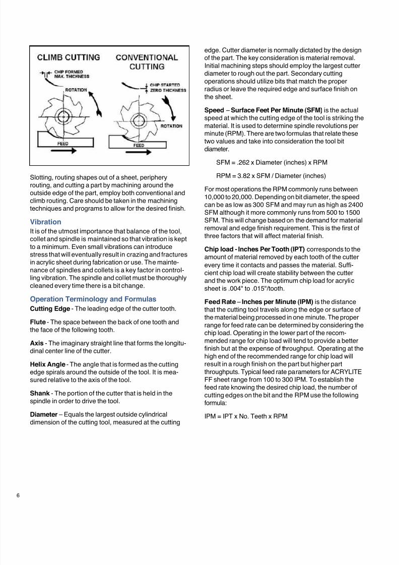
Direction of TravelProper feed direction is essential for a smooth cut.Routers rotate clockwise when viewed from the spindleor colleted side of the router. This is also referred to asRight Hand Cutting. If a hand held router is fed into thesheet in a clockwise direction, the cutting edges of thebit will pull the bit into the work rendering control nearlyimpossible. This routing method is referred to as ClimbCutting. Climb Cutting should only be used on machinerythat has rigid spindles and worktables that are free ofleadscrew backlash. Climb Cutting will improve productsurface finish and increase tool life.
Note: This type of machining can only be done on CNCmachinery. Climb Cutting is not recommended for mostrouting applications.
The feed direction for external cuts should be counter-clockwise. When routing inside edges, the router shouldbe fed clockwise. This practice will allow an operator tomaintain proper control of the router and attain a smoothedge. This method is referred to as Conventional Cut-ting.
Note: Conventional Cutting is the recommended methodfor most routing operations. Refer to the routing direction
diagram on page 6.
7/23/2019 Acrylite Fabrication Guide
http://slidepdf.com/reader/full/acrylite-fabrication-guide 24/66
6
Slotting, routing shapes out of a sheet, peripheryrouting, and cutting a part by machining around theoutside edge of the part, employ both conventional andclimb routing. Care should be taken in the machiningtechniques and programs to allow for the desired finish.
Vibration
It is of the utmost importance that balance of the tool,collet and spindle is maintained so that vibration is keptto a minimum. Even small vibrations can introducestress that will eventually result in crazing and fracturesin acrylic sheet during fabrication or use. The mainte-nance of spindles and collets is a key factor in control-ling vibration. The spindle and collet must be thoroughlycleaned every time there is a bit change.
Operation Terminology and FormulasCutting Edge - The leading edge of the cutter tooth.
Flute - The space between the back of one tooth andthe face of the following tooth.
Axis - The imaginary straight line that forms the longitu-dinal center line of the cutter.
Helix Angle - The angle that is formed as the cuttingedge spirals around the outside of the tool. It is mea-sured relative to the axis of the tool.
Shank - The portion of the cutter that is held in thespindle in order to drive the tool.
Diameter – Equals the largest outside cylindricaldimension of the cutting tool, measured at the cutting
edge. Cutter diameter is normally dictated by the designof the part. The key consideration is material removal.Initial machining steps should employ the largest cutterdiameter to rough out the part. Secondary cuttingoperations should utilize bits that match the properradius or leave the required edge and surface finish on
the sheet.
Speed – Surface Feet Per Minute (SFM) is the actualspeed at which the cutting edge of the tool is striking thematerial. It is used to determine spindle revolutions perminute (RPM). There are two formulas that relate thesetwo values and take into consideration the tool bitdiameter.
SFM = .262 x Diameter (inches) x RPM
RPM = 3.82 x SFM / Diameter (inches)
For most operations the RPM commonly runs between
10,000 to 20,000. Depending on bit diameter, the speedcan be as low as 300 SFM and may run as high as 2400SFM although it more commonly runs from 500 to 1500SFM. This will change based on the demand for materialremoval and edge finish requirement. This is the first ofthree factors that will affect material finish.
Chip load - Inches Per Tooth (IPT) corresponds to theamount of material removed by each tooth of the cutterevery time it contacts and passes the material. Suffi-cient chip load will create stability between the cutterand the work piece. The optimum chip load for acrylicsheet is .004" to .015"/tooth.
Feed Rate – Inches per Minute (IPM) is the distancethat the cutting tool travels along the edge or surface ofthe material being processed in one minute. The properrange for feed rate can be determined by considering thechip load. Operating in the lower part of the recom-mended range for chip load will tend to provide a betterfinish but at the expense of throughput. Operating at thehigh end of the recommended range for chip load willresult in a rough finish on the part but higher partthroughputs. Typical feed rate parameters for ACRYLITEFF sheet range from 100 to 300 IPM. To establish thefeed rate knowing the desired chip load, the number of
cutting edges on the bit and the RPM use the followingformula:
IPM = IPT x No. Teeth x RPM
7/23/2019 Acrylite Fabrication Guide
http://slidepdf.com/reader/full/acrylite-fabrication-guide 25/66
Trouble Shooting
Problem Cause Solution
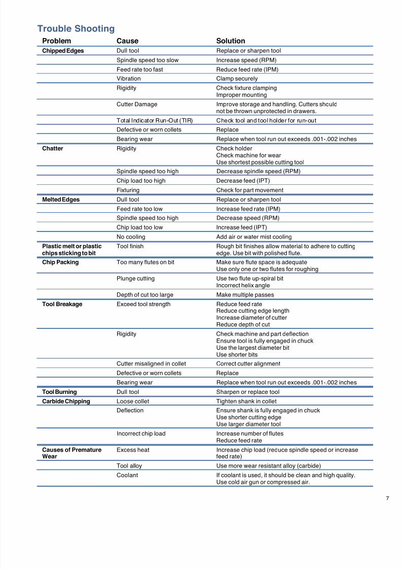
Chipped Edges Dull tool Replace or sharpen tool
Spindle speed too slow Increase speed (RPM)
Feed rate too fast Reduce feed rate (IPM)
Vibration Clamp securely
Rigidity Check fixture clampingImproper mounting
Cutter Damage Improve storage and handling. Cutters shouldnot be thrown unprotected in drawers.
Total Indicator Run-Out (TIR) Check tool and tool holder for run-out
Defective or worn collets Replace
Bearing wear Replace when tool run out exceeds .001-.002 inches
Chatter Rigidity Check holderCheck machine for wearUse shortest possible cutting tool
Spindle speed too high Decrease spindle speed (RPM)
Chip load too high Decrease feed (IPT)
Fixturing Check for part movement
Melted Edges Dull tool Replace or sharpen toolFeed rate too low Increase feed rate (IPM)
Spindle speed too high Decrease speed (RPM)
Chip load too low Increase feed (IPT)
No cooling Add air or water mist cooling
Plastic melt or plastic Tool finish Rough bit finishes allow material to adhere to cuttingchips sticking to bit edge. Use bit with polished flute.
Chip Packing Too many flutes on bit Make sure flute space is adequateUse only one or two flutes for roughing
Plunge cutting Use two flute up-spiral bitIncorrect helix angle
Depth of cut too large Make multiple passes
Tool Breakage Exceed tool strength Reduce feed rateReduce cutting edge lengthIncrease diameter of cutterReduce depth of cut
Rigidity Check machine and part deflectionEnsure tool is fully engaged in chuckUse the largest diameter bitUse shorter bits
Cutter misaligned in collet Correct cutter alignment
Defective or worn collets Replace
Bearing wear Replace when tool run out exceeds .001-.002 inches
Tool Burning Dull tool Sharpen or replace tool
Carbide Chipping Loose collet Tighten shank in collet
Deflection Ensure shank is fully engaged in chuckUse shorter cutting edgeUse larger diameter tool
Incorrect chip load Increase number of flutesReduce feed rate
Causes of Premature Excess heat Increase chip load (reduce spindle speed or increaseWear feed rate)
Tool alloy Use more wear resistant alloy (carbide)
Coolant If coolant is used, it should be clean and high quality.Use cold air gun or compressed air.

7/23/2019 Acrylite Fabrication Guide
http://slidepdf.com/reader/full/acrylite-fabrication-guide 26/66
8
Equipment and Materials Suppliers
The suppliers listed below offer materials and equipment tested and approved by CYRO Industries.Authorized ACRYLITE Sheet Distributors may also offer materials and equipment. Visit www.cyro.comfor a list of authorized CYRO sheet distributors.
Router Bits
Ekstrom, Carlson & Co.
5196 27th AvenueP.O. Box 1611Rockford, IL 61109815-394-1744Fax: 815-398-9439www.ekstromcarlson.com
Great Lakes Carbide Tool Mfg., Inc.
101 N. Old Peshtigo Road
Peshtigo, WI 54157715-582-3884Fax: 715-582-4373www.glct.com
Kennametal, Inc.
1600 Technology WayLatrobe, PA 15650-0231724-539-5000800-446-7738www.kennametal.com
Onsrud Cutter, Inc.
800 Liberty DriveLiberty, IL 60048800-234-1560Fax: 800-557-6720www.onsrud.com
Paso Robles Carbide, Inc.
731-C Paso Robles StreetPaso Robles, CA 93446805-238-6144Fax: 805-238-4263
Continued on next page
Toolmasters LLC
1400 Railroad AvenuePO Box 1611Rockford, IL 61110815-968-0961Fax: 815-968-5559www.toolmastersllc.com
Trend Lines, Inc.
100 Justin DriveChelsea, MA 02150800-767-9999
Fax: 800-735-3825www.trend-lines.com
Union Butterfield
P.O. Box 50000Asheville, North Carolina 28813800-222-8665Fax: 800-432-9482www.unionbutterfield.com
Wisconsin Knife Works
2505 Kennedy DriveBeloit, WI 53511
800-225-5959Fax: 800-336-1254www.wkwinc.com
Woodworkers Supply
125 Jay LaneGraham, NC 27253800-645-9292Fax: 800-853-WOODor 336-578-1401www.woodworker.com
7/23/2019 Acrylite Fabrication Guide
http://slidepdf.com/reader/full/acrylite-fabrication-guide 27/66
Collets and Tool Holders
Centaur Precision Tools Inc.
13098 SW 133 CourtMiami, FL 33186888-COLLETSFax: 305-251-0756www.centaurtools.com
REGO-FIX Tools
7752 Moller Rd.Indianapolis, IN 46268
800-734-6349Fax: 317-870-5955www.rego-fix.com
Routers
Black & Decker Mfg. Co.
701 E. Joppa RoadTowson, MD 21287410-716-3900www.blackanddecker.com
C.R. Onsrud, Inc.
867 S. Main StreetTroutman, NC 28166704-528-4528Fax: 704-528-6170www.cronsrud.com
Delta International
4290 E Raines RoadMemphis, TN 38118800-223-7278Fax: 800-535-6488www.delta-portercable.com
Gerber Scientific Products, Inc.151 Batson DriveManchester, CT 06040800-222-7446Fax: 860-645-5645www.gspinc.com
KOMO Machine, Inc.
11 Industrial Blvd.Sauk Rapids, MN 56379800-255-5670Fax: 320-656-2470www.komo.com
MultiCam, Inc.
8920 North Royal LaneIrving, TX 75063972-929-4070Fax: 972-929-4071
www.multicam.com
SB Power Tool Corp.
4300 W. PetersonChicago, IL 60646888-394-4646800-301-TALK Fax: 800-547-1998
Shoda CNC Routers
www.shodausa.comwww.boschtools.com
Skil Tools
877-754-5999www.skiltools.com
Thermwood Corp.
P.O. Box 436Dale, IN 47523800-533-6901Fax: 812-937-2956www.thermwood.com
Equipment and Materials Suppliers Continued from previous page

7/23/2019 Acrylite Fabrication Guide
http://slidepdf.com/reader/full/acrylite-fabrication-guide 28/66
10 1319(5F)-0302-5RA © 2002 CYRO Industries. All rights reserved. Printed in USA.
CYRO Industries, Parsippany, New Jersey 07054
Fire PrecautionsACRYLITE FF sheet is a combustible thermoplastic. Precautions should be taken to protect this material from flames and high heat sources. ACRYLITE FF sheet
usually burns rapidly to completion if not extinguished. The products of combustion, if sufficient air is present, are carbon dioxide and water. However, in many firessufficient air will not be available and toxic carbon monoxide will be formed, as it will when other common combustible materials are burned. We urge good judgementin the use of this versatile material and recommend that building codes be followed carefully to assure it is used properly.
Compatibility
Like other plastic materials, ACRYLITE FF sheet is subject to crazing, cracking or discoloration if brought into contact with incompatible materials. These materialsmay include cleaners, polishes, adhesives, sealants, gasketing or packaging materials, cutting emulsions, etc. See the Tech Briefs in this series for more informa-tion, or contact your ACRYLITE Sheet Distributor or the CYRO Technical Center for information on a specific product.
Important Notice
The information and statements herein are believed to be reliable but are not to be construed as a warranty or representation for which we assume legal responsibility.Users should undertake sufficient verification and testing to determine the suitability for their own particular purpose of any information or products referred to herein.NO WARRANTY OF FITNESS FOR PARTICULAR PURPOSE IS MADE. Nothing herein is to be taken as permission, inducement or recommendation to practice anypatented invention without a license.
Additional Technical Informationand Assistance
We invite you to visit our TechKnowlogy Centeron www.cyro.com.Visitors have immediate access to frequently askedquestions, technical concerns, physical properties,processing conditions, fabrication tips,regulatory compliance information,engineering guidelines, tips fortroubleshooting, and hundredsof other facts about acrylicsfrom one of North America’sleading manufacturers ofacrylic-based polymer andsheet products.
For additional information contact:Degussa, CYRO Industries 379 Interpace Parkway,
PO Box 677, Parsippany, NJ 07054-0677
800-631-5384www.cyro.comwww.degussa.com
CYRO Industries is a wholly-owned subsidiary of Degussa.
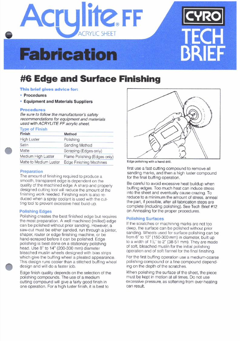
7/23/2019 Acrylite Fabrication Guide
http://slidepdf.com/reader/full/acrylite-fabrication-guide 29/66
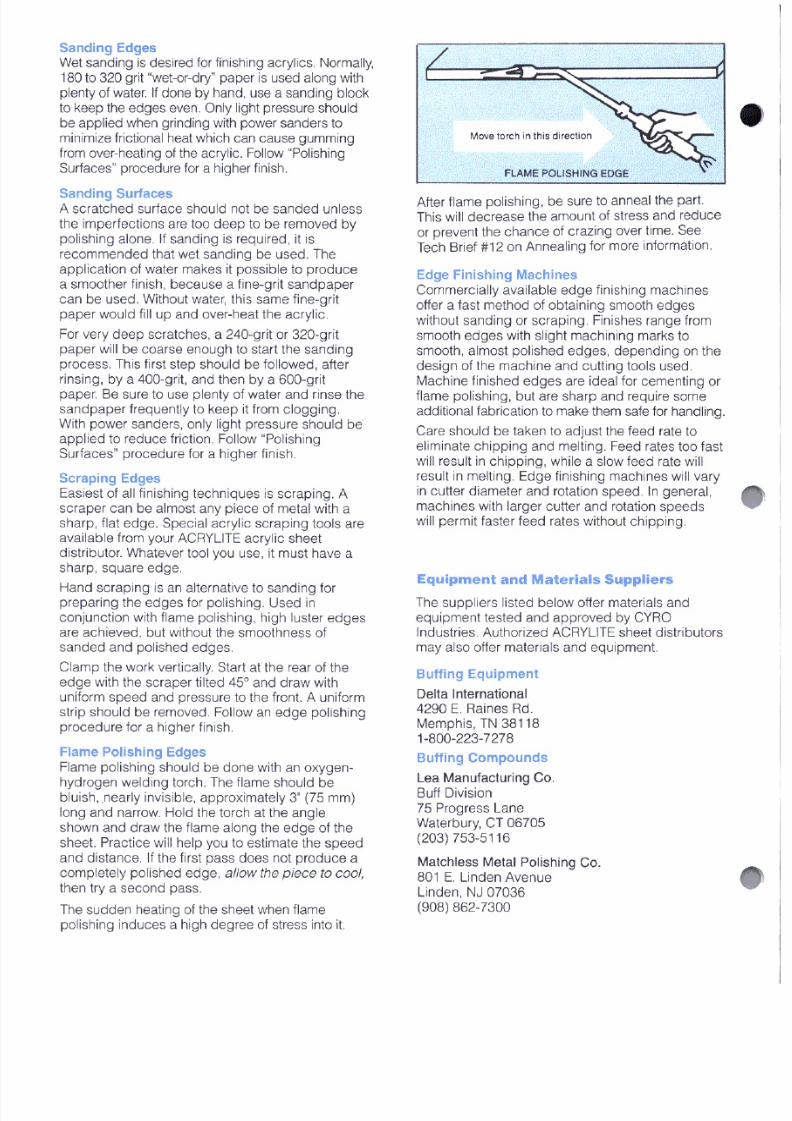
7/23/2019 Acrylite Fabrication Guide
http://slidepdf.com/reader/full/acrylite-fabrication-guide 30/66
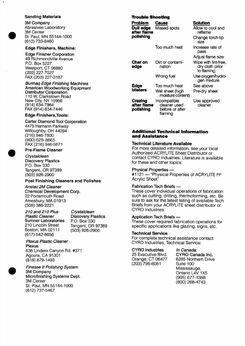
7/23/2019 Acrylite Fabrication Guide
http://slidepdf.com/reader/full/acrylite-fabrication-guide 31/66
7/23/2019 Acrylite Fabrication Guide
http://slidepdf.com/reader/full/acrylite-fabrication-guide 32/66
Degussa, CYRO Industries, 379 Interpace Parkway, PO Box 677, Parsippany,
NJ 07054 800-631-5384 www.cyro.com www.degussa.com
Degussa, CYRO Industries, 379 Interpace Parkway, PO Box 677, Parsippany, NJ 07054 800-631-5384 www.cyro.com www.degussa.com

7/23/2019 Acrylite Fabrication Guide
http://slidepdf.com/reader/full/acrylite-fabrication-guide 33/66
Fabrication
#7 Line BendingThis brief gives advice for:
Equipment
Procedures
Trouble Shooting
Equipment Suppliers
Additional Technical Information& Assistance
TECH
BRIEF
Equipment
Straight Nichrome Resistance Wire Heater
To bend ACRYLITE® FF acrylic sheet up to 1/8" (3mm)thick, the most commonly used piece of equipment is
a straight nichrome wire resistance heater. The unitfunctions similarly to a household electric toaster bypassing electricity through a wire.
You can bend material thicker than 1/8" (3mm) on thisunit, but the material must be flipped over halfway duringthe heating cycle.
In constructing the heater, use plywood for the base.The top surface should be insulation board or aluminumsheet to provide a smooth surface, helping preventmark-off marks on the sheet as a result of contact.Aluminum is selected as the metal alternative becauseit is durable and does not absorb and re-radiate heat.
The heating element is a 17-gauge nichrome (nickel-chrome) wire. Attach the wire to a 120-volt, 20-ampvariable transformer. Provide a spring as shown to keepthe wire under tension. Allow space around the wire forfree air flow to aid heat transfer from the wire to the part.Position the wire so it remains at least 1/8" from thesheet during heating. Ceramic stand-offs are useful insupporting the wire at a consistent height from the base
(see last page for source of supply).
CAUTION: An unguarded nichrome wire is a burn/
shock hazard. Provide a guard to prevent contact
with the wire.
Modification for Multiple Line Bends
To perform multiple line bends, modify the heater as
shown above. Where the wire joins the spring, includean insulation ring. Raise the unit’s base so convectionair from below flows through slots routed in the base asshown.
Coiled Resistance Wire
Coiled resistance wire can be substituted for straightwire as a heating element. Because coiled wire must besupported and because it is difficult to position the coilsevenly, temperatures across the sheet’s width mayvary, causing uneven stresses and distortion. See thefollowing section under Procedures entitled Line
Bending with Coiled Resistance Wire.
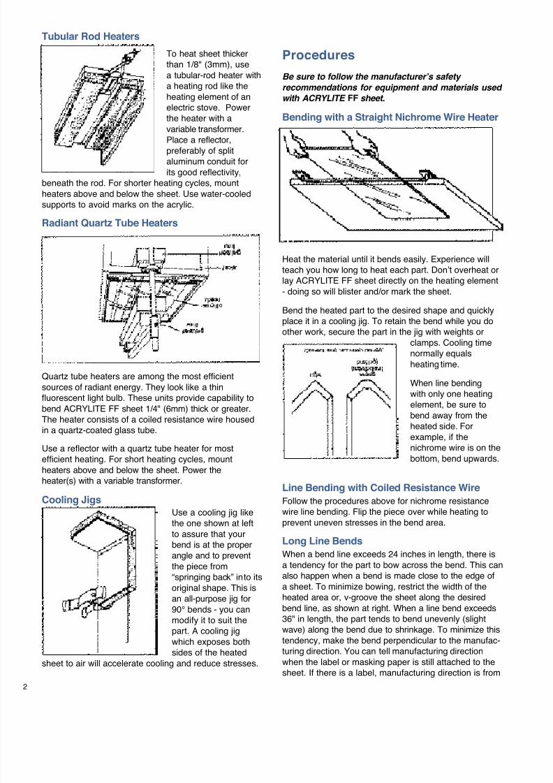
7/23/2019 Acrylite Fabrication Guide
http://slidepdf.com/reader/full/acrylite-fabrication-guide 34/66
2
Procedures
Be sure to follow the manufacturer’s safety
recommendations for equipment and materials used
with ACRYLITE FF sheet.
Bending with a Straight Nichrome Wire Heater
Heat the material until it bends easily. Experience will
teach you how long to heat each part. Don’t overheat orlay ACRYLITE FF sheet directly on the heating element- doing so will blister and/or mark the sheet.
Bend the heated part to the desired shape and quicklyplace it in a cooling jig. To retain the bend while you doother work, secure the part in the jig with weights or
clamps. Cooling timenormally equalsheating time.
When line bendingwith only one heatingelement, be sure tobend away from theheated side. Forexample, if thenichrome wire is on thebottom, bend upwards.
Line Bending with Coiled Resistance Wire
Follow the procedures above for nichrome resistancewire line bending. Flip the piece over while heating toprevent uneven stresses in the bend area.
Long Line Bends
When a bend line exceeds 24 inches in length, there isa tendency for the part to bow across the bend. This canalso happen when a bend is made close to the edge ofa sheet. To minimize bowing, restrict the width of theheated area or, v-groove the sheet along the desiredbend line, as shown at right. When a line bend exceeds36" in length, the part tends to bend unevenly (slightwave) along the bend due to shrinkage. To minimize thistendency, make the bend perpendicular to the manufac-turing direction. You can tell manufacturing directionwhen the label or masking paper is still attached to thesheet. If there is a label, manufacturing direction is from
To heat sheet thickerthan 1/8" (3mm), usea tubular-rod heater witha heating rod like theheating element of anelectric stove. Powerthe heater with avariable transformer.
Place a reflector,preferably of splitaluminum conduit forits good reflectivity,
beneath the rod. For shorter heating cycles, mountheaters above and below the sheet. Use water-cooledsupports to avoid marks on the acrylic.
Radiant Quartz Tube Heaters
Quartz tube heaters are among the most efficientsources of radiant energy. They look like a thinfluorescent light bulb. These units provide capability to
bend ACRYLITE FF sheet 1/4" (6mm) thick or greater.The heater consists of a coiled resistance wire housedin a quartz-coated glass tube.
Use a reflector with a quartz tube heater for mostefficient heating. For short heating cycles, mountheaters above and below the sheet. Power theheater(s) with a variable transformer.
Cooling Jigs
Use a cooling jig likethe one shown at leftto assure that your
bend is at the properangle and to preventthe piece from“springing back” into itsoriginal shape. This isan all-purpose jig for90° bends - you canmodify it to suit thepart. A cooling jigwhich exposes bothsides of the heated
sheet to air will accelerate cooling and reduce stresses.
Tubular Rod Heaters
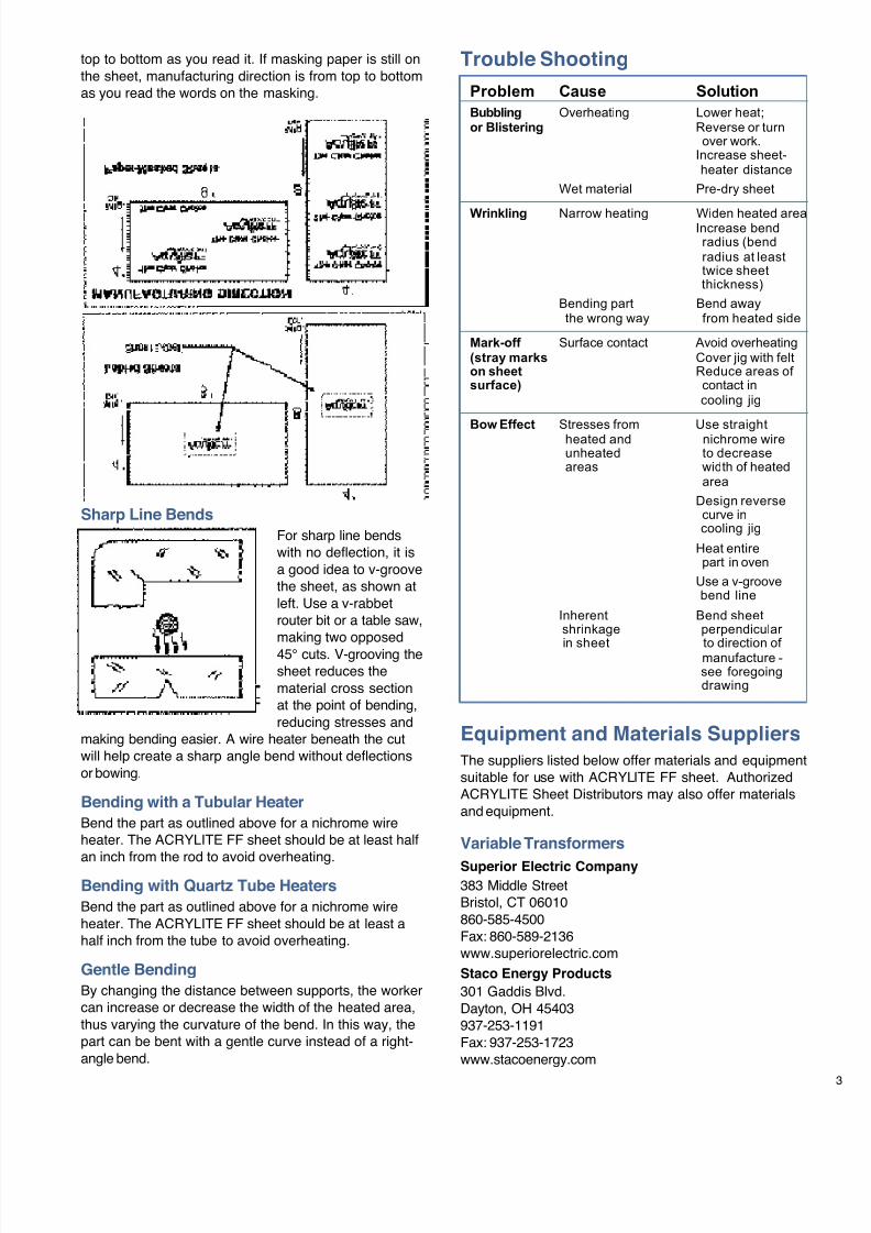
7/23/2019 Acrylite Fabrication Guide
http://slidepdf.com/reader/full/acrylite-fabrication-guide 35/66
top to bottom as you read it. If masking paper is still onthe sheet, manufacturing direction is from top to bottomas you read the words on the masking.
Sharp Line Bends
For sharp line bendswith no deflection, it isa good idea to v-groovethe sheet, as shown atleft. Use a v-rabbetrouter bit or a table saw,making two opposed45° cuts. V-grooving thesheet reduces thematerial cross sectionat the point of bending,reducing stresses and
making bending easier. A wire heater beneath the cutwill help create a sharp angle bend without deflectionsor bowing.
Bending with a Tubular Heater
Bend the part as outlined above for a nichrome wireheater. The ACRYLITE FF sheet should be at least half
an inch from the rod to avoid overheating.Bending with Quartz Tube Heaters
Bend the part as outlined above for a nichrome wireheater. The ACRYLITE FF sheet should be at least ahalf inch from the tube to avoid overheating.
Gentle Bending
By changing the distance between supports, the workercan increase or decrease the width of the heated area,thus varying the curvature of the bend. In this way, thepart can be bent with a gentle curve instead of a right-angle bend.
Trouble Shooting
Problem Cause Solution
Bubbling Overheating Lower heat;or Blistering Reverse or turn
over work.Increase sheet- heater distance
Wet material Pre-dry sheet
Wrinkling Narrow heating Widen heated areaIncrease bend radius (bend radius at least twice sheet thickness)
Bending part Bend away the wrong way from heated side
Mark-off Surface contact Avoid overheating(stray marks Cover jig with felton sheet Reduce areas of surface) contact in
cooling jig
Bow Effect Stresses from Use straight heated and nichrome wire unheated to decrease areas width of heated
area
Design reverse curve in cooling jig
Heat entire part in oven
Use a v-groove bend line
Inherent Bend sheet shrinkage perpendicular
in sheet to direction of manufacture - see foregoing drawing
Equipment and Materials Suppliers
The suppliers listed below offer materials and equipmentsuitable for use with ACRYLITE FF sheet. AuthorizedACRYLITE Sheet Distributors may also offer materialsand equipment.
Variable Transformers
Superior Electric Company383 Middle StreetBristol, CT 06010860-585-4500Fax: 860-589-2136www.superiorelectric.com
Staco Energy Products
301 Gaddis Blvd.Dayton, OH 45403937-253-1191Fax: 937-253-1723www.stacoenergy.com
7/23/2019 Acrylite Fabrication Guide
http://slidepdf.com/reader/full/acrylite-fabrication-guide 36/66
4 1319(7F)-0901-5RA
Nichrom Wire/Strip Heaters
Pelican Wire Company
6266 Taylor RoadNaples, FL 34109-1896941-597-8555Fax: 941-597-9783www.pelicanwire.com
Ceramic Stand-offs
CHROMALOXEdwin L. Wiegand DivisionEmerson Electric Co.103 Gamma Drive ExtensionPittsburgh, PA 15238412-967-3800Fax: 412-967-5148www.chromalox.com
Equipment
Edge Finisher Corporation
16 Stony Hill RoadBethel, CT 06801203-796-7923Fax: 203-796-7924www.edgefinisher.com
FTM, Inc.
6160 Cobblestone RoadPlacerville, CA 95667530-626-1986Fax: 530-642-2602www.thefabricatorssouce.com
C.R. Clarke & Company
4407 Vineland Road - Suite D5Orlando, FL 32811
800-676-7133www.crclarke.co.uk
Additional Technical Informationand AssistanceWe invite you to visit our TechKnowlogy Center
on www.cyro.com.
Visitors have immediate access to frequently askedquestions, technical concerns, physical properties,processing conditions, fabrication tips, regulatorycompliance information, engineering guidelines, tips
for troubleshooting, and hundreds of other facts aboutacrylics from one of North America’s leadingmanufacturers of acrylic-basedpolymer and sheet products.
© 2001 CYRO Industries. All Rights Reserved. Printed in USA.
CYRO Industries, Parsippany, New Jersey 07054
Fire Precautions
ACRYLITE FF sheet is a combustible thermoplastic. Precautions should betaken to protect this material from flames and high heat sources. ACRYLITE FFsheet usually burns rapidly to completion if not extinguished. The products of
combustion, if sufficient air is present, are carbon dioxide and water. However,in many fires sufficient air will not be available and toxic carbon monoxide willbe formed, as it will when other common combustible materials are burned. Weurge good judgement in the use of this versatile material and recommend thatbuilding codes be followed carefully to assure it is used properly.
Compatibility
Like other plastic materials, ACRYLITE FF sheet is subject to crazing, crackingor discoloration if brought into contact with incompatible materials. Thesematerials may include cleaners, polishes, adhesives, sealants, gasketing or
packaging materials, cutting emulsions, etc. See the Tech Briefs in this seriesfor more information, or contact your ACRYLITE Sheet Distributor or the CYRO
Technical Center for information on a specific product.
Important Notice:
The information and statements herein are believed to be reliable but are not tobe construed as a warranty or representation for which we assume legalresponsibility. Users should undertake sufficient verification and testing to
determine the suitability for their own particular purpose of any information orproducts referred to herein. NO WARRANTY OF FITNESS FOR PARTICULARPURPOSE IS MADE. Nothing herein is to be taken as permission, inducementor recommendation to practice any patented invention without a license.
Sales Offices
For the name of your local Authorized Distributor,call 800-631-5384, visit www.cyro.com, or contactthe nearest regional sales office.
Eastern Region
100 Enterpise Drive
PO Box 5055Rockaway, NJ 07866973-442-6130
South/Central Region
101 East Park Blvd.Suite 1039Plano, TX 75074972-424-6830
Western Region
3180 Crow Canyon Place
Suite 240San Ramon, CA 94583925-866-9300
CYRO Canada Inc.
6285 Northam DriveSuite 100Mississauga,Ontario L4V 1X5905-677-1388800-268-4743
3
com
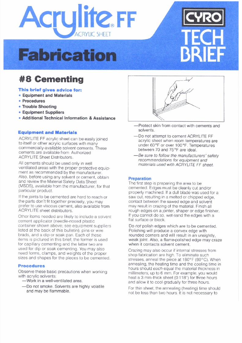
7/23/2019 Acrylite Fabrication Guide
http://slidepdf.com/reader/full/acrylite-fabrication-guide 37/66
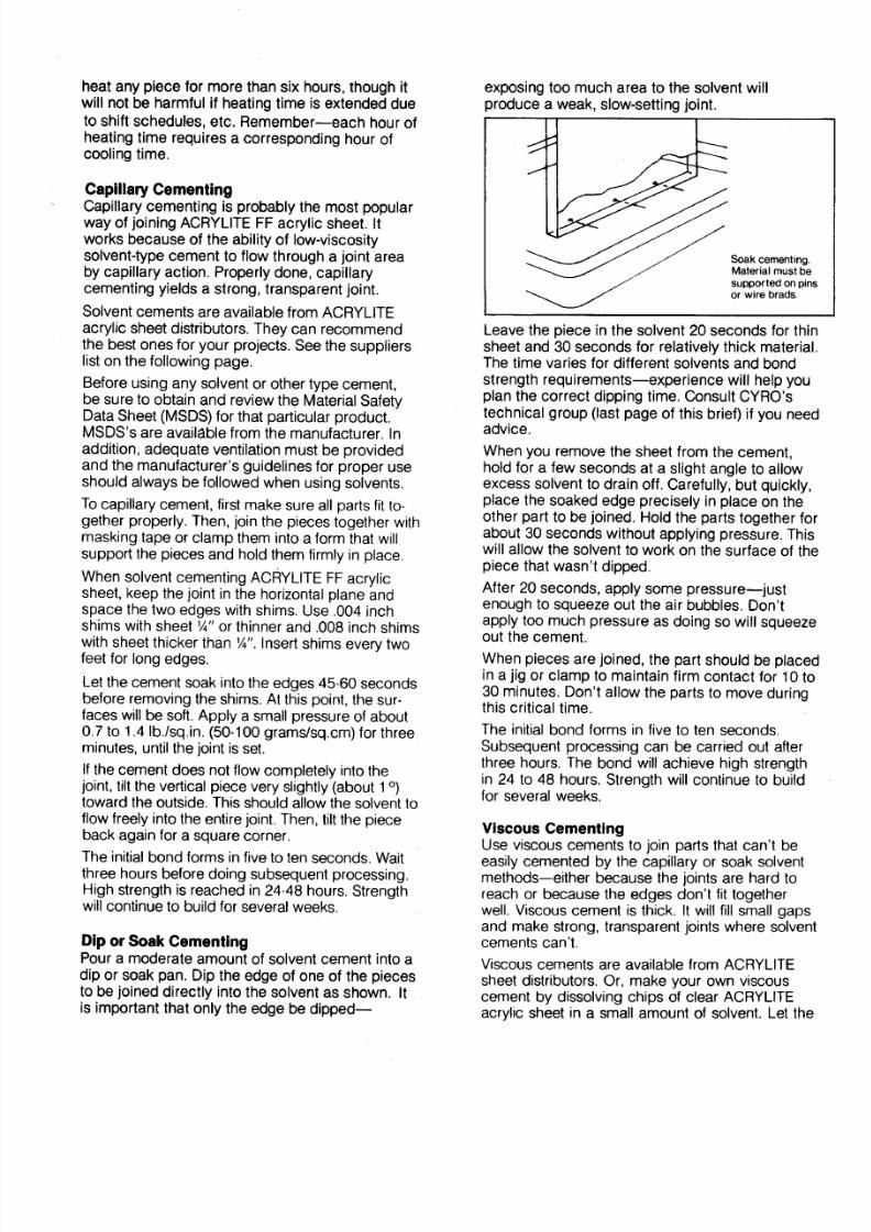
7/23/2019 Acrylite Fabrication Guide
http://slidepdf.com/reader/full/acrylite-fabrication-guide 38/66
7/23/2019 Acrylite Fabrication Guide
http://slidepdf.com/reader/full/acrylite-fabrication-guide 39/66
7/23/2019 Acrylite Fabrication Guide
http://slidepdf.com/reader/full/acrylite-fabrication-guide 40/66
For additional information contact:
Degussa, CYRO Industries
379 Interpace Parkway
PO Box 677
Parsippany, NJ 07054
800-631-5384
www.cyro.com
www.degussa.com
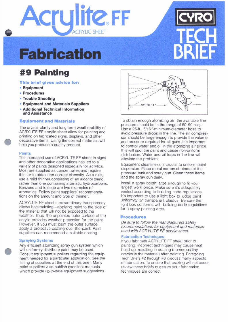
7/23/2019 Acrylite Fabrication Guide
http://slidepdf.com/reader/full/acrylite-fabrication-guide 41/66
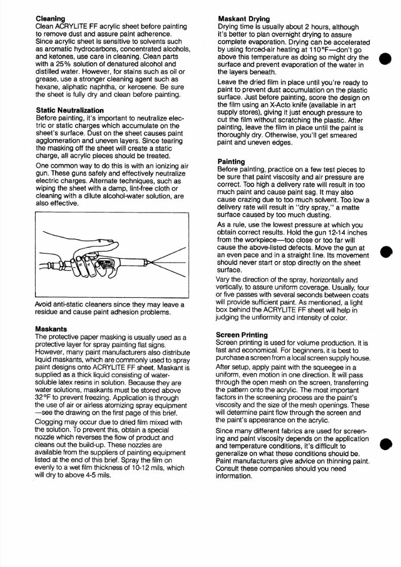
7/23/2019 Acrylite Fabrication Guide
http://slidepdf.com/reader/full/acrylite-fabrication-guide 42/66
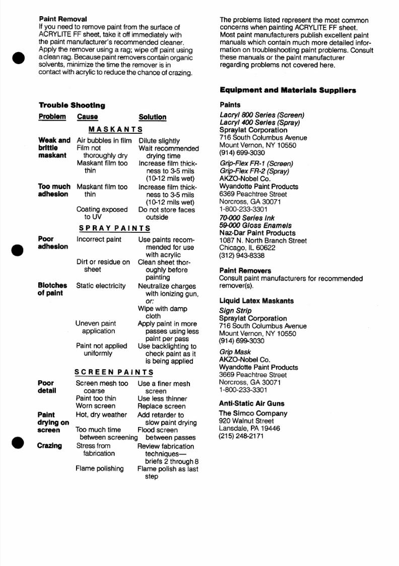
7/23/2019 Acrylite Fabrication Guide
http://slidepdf.com/reader/full/acrylite-fabrication-guide 43/66
7/23/2019 Acrylite Fabrication Guide
http://slidepdf.com/reader/full/acrylite-fabrication-guide 44/66
For additional information contact:
Degussa, CYRO Industries
379 Interpace Parkway,
PO Box 677, Parsippany, NJ 07054
800-631-5384www.cyro.com
www.degussa.com
Degussa, CYRO Industries, 379 Interpace Parkway, PO Box 677, Parsippany, NJ07054 800-631-5384 www.cyro.com www.degussa.com
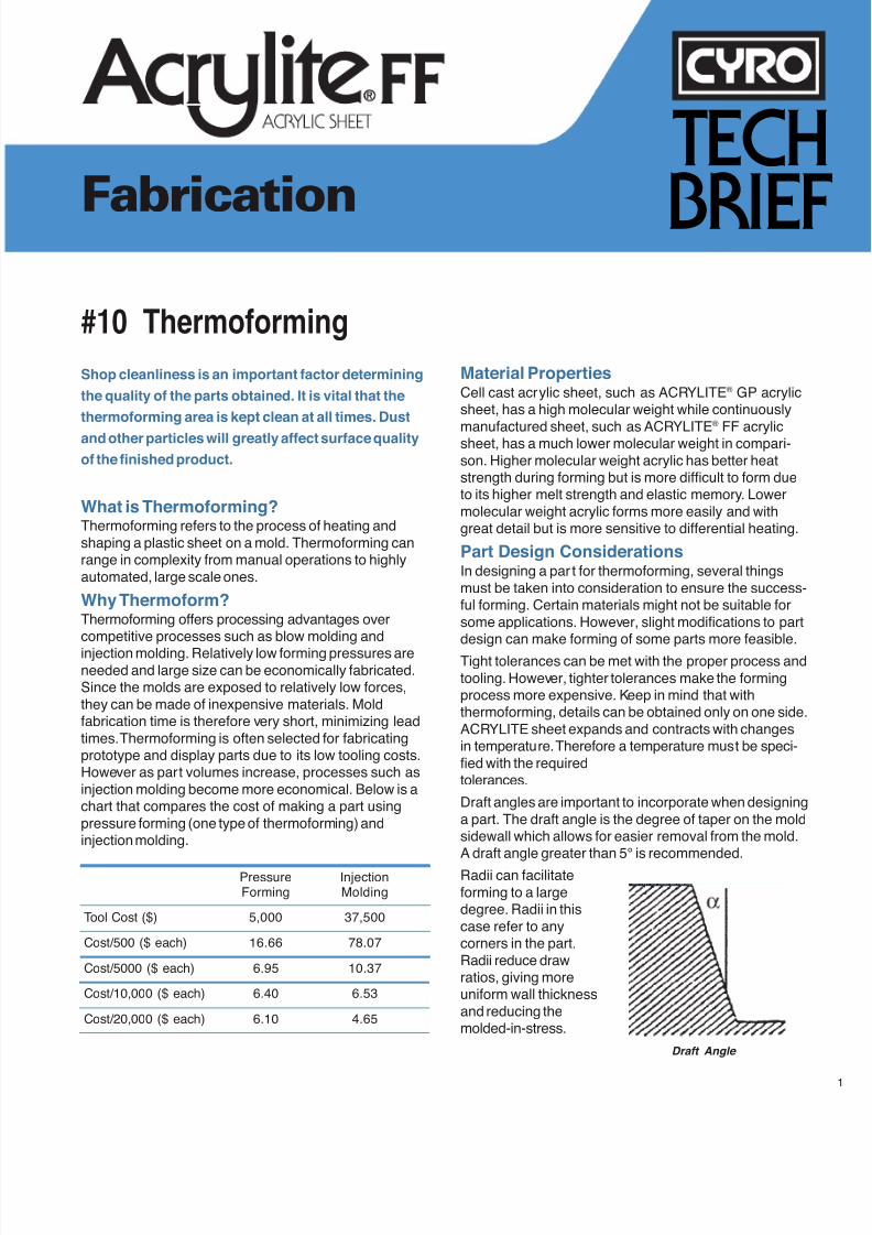
7/23/2019 Acrylite Fabrication Guide
http://slidepdf.com/reader/full/acrylite-fabrication-guide 45/66
Fabrication
#10 Thermoforming
TECH
BRIEF
What is Thermoforming?Thermoforming refers to the process of heating andshaping a plastic sheet on a mold. Thermoforming canrange in complexity from manual operations to highlyautomated, large scale ones.
Why Thermoform?Thermoforming offers processing advantages overcompetitive processes such as blow molding and
injection molding. Relatively low forming pressures areneeded and large size can be economically fabricated.Since the molds are exposed to relatively low forces,they can be made of inexpensive materials. Moldfabrication time is therefore very short, minimizing leadtimes. Thermoforming is often selected for fabricatingprototype and display parts due to its low tooling costs.However as part volumes increase, processes such asinjection molding become more economical. Below is achart that compares the cost of making a part usingpressure forming (one type of thermoforming) andinjection molding.
Pressure InjectionForming Molding
Tool Cost ($) 5,000 37,500
Cost/500 ($ each) 16.66 78.07
Cost/5000 ($ each) 6.95 10.37
Cost/10,000 ($ each) 6.40 6.53
Cost/20,000 ($ each) 6.10 4.65
Shop cleanliness is an important factor determining
the quality of the parts obtained. It is vital that the
thermoforming area is kept clean at all times. Dust
and other particles will greatly affect surface quality
of the finished product.
Material PropertiesCell cast acrylic sheet, such as ACRYLITE® GP acrylicsheet, has a high molecular weight while continuously
manufactured sheet, such as ACRYLITE®
FF acrylicsheet, has a much lower molecular weight in compari-son. Higher molecular weight acrylic has better heatstrength during forming but is more difficult to form dueto its higher melt strength and elastic memory. Lowermolecular weight acrylic forms more easily and withgreat detail but is more sensitive to differential heating.
Part Design ConsiderationsIn designing a par t for thermoforming, several thingsmust be taken into consideration to ensure the success-ful forming. Certain materials might not be suitable forsome applications. However, slight modifications to partdesign can make forming of some parts more feasible.
Tight tolerances can be met with the proper process andtooling. However, tighter tolerances make the formingprocess more expensive. Keep in mind that withthermoforming, details can be obtained only on one side.ACRYLITE sheet expands and contracts with changesin temperature. Therefore a temperature must be speci-fied with the requiredtolerances.
Draft angles are important to incorporate when designinga part. The draft angle is the degree of taper on the moldsidewall which allows for easier removal from the mold.A draft angle greater than 5° is recommended.
Radii can facilitateforming to a largedegree. Radii in thiscase refer to anycorners in the part.Radii reduce drawratios, giving moreuniform wall thicknessand reducing themolded-in-stress.
Draft Angle
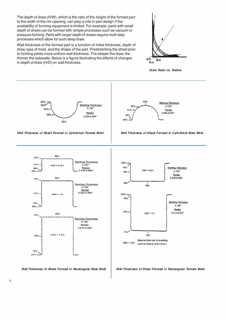
7/23/2019 Acrylite Fabrication Guide
http://slidepdf.com/reader/full/acrylite-fabrication-guide 46/66
2
The depth of draw (H/W), which is the ratio of the height of the formed partto the width of the rim opening, can play a role in part design if theavailability of forming equipment is limited. For example, parts with smalldepth of draws can be formed with simple processes such as vacuum orpressure forming. Parts with larger depth of draws require multi-stepprocesses which allow for such deep draw.
Wall thickness of the formed part is a function of initial thickness, depth ofdraw, type of mold, and the shape of the part. Prestretching the sheet priorto forming yields more uniform wall thickness. The deeper the draw, thethinner the sidewalls. Below is a figure illustrating the effects of changesin depth of draw (H/D) on wall thickness.
Wall Thickness of Sheet Formed in Cylindrical Female Mold Wall Thickness of Sheet Formed in Cylindrical Male Mold
Wall Thickness of Sheet Formed in Rectangular Male Mold Wall Thickness of Sheet Formed in Rectangular Female Mold
Draw Ratio vs. Radius
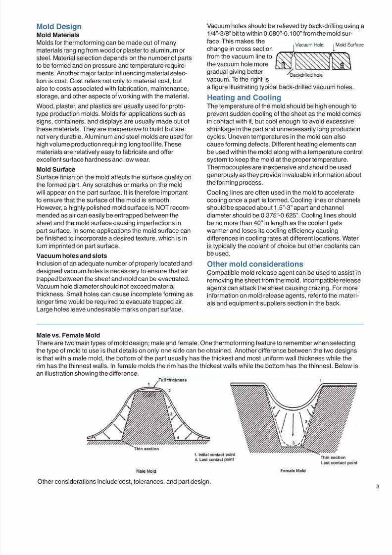
7/23/2019 Acrylite Fabrication Guide
http://slidepdf.com/reader/full/acrylite-fabrication-guide 47/66
Mold DesignMold Materials
Molds for thermoforming can be made out of manymaterials ranging from wood or plaster to aluminum orsteel. Material selection depends on the number of partsto be formed and on pressure and temperature require-ments. Another major factor influencing material selec-tion is cost. Cost refers not only to material cost, butalso to costs associated with fabrication, maintenance,
storage, and other aspects of working with the material.Wood, plaster, and plastics are usually used for proto-type production molds. Molds for applications such assigns, containers, and displays are usually made out ofthese materials. They are inexpensive to build but arenot very durable. Aluminum and steel molds are used forhigh volume production requiring long tool l ife. Thesematerials are relatively easy to fabricate and offerexcellent surface hardness and low wear.
Mold Surface
Surface finish on the mold affects the surface quality onthe formed part. Any scratches or marks on the mold
will appear on the part surface. It is therefore importantto ensure that the surface of the mold is smooth.However, a highly polished mold surface is NOT recom-mended as air can easily be entrapped between thesheet and the mold surface causing imperfections inpart surface. In some applications the mold surface canbe finished to incorporate a desired texture, which is inturn imprinted on part surface.
Vacuum holes and slots
Inclusion of an adequate number of properly located anddesigned vacuum holes is necessary to ensure that airtrapped between the sheet and mold can be evacuated.Vacuum hole diameter should not exceed material
thickness. Small holes can cause incomplete forming aslonger time would be required to evacuate trapped air.Large holes leave undesirable marks on part surface.
Male vs. Female Mold
There are two main types of mold design; male and female. One thermoforming feature to remember when selectingthe type of mold to use is that details on only one side can be obtained. Another difference between the two designsis that with a male mold, the bottom of the part usually has the thickest and most uniform wall thickness while therim has the thinnest walls. In female molds the rim has the thickest walls while the bottom has the thinnest. Below isan illustration showing the difference.
Vacuum holes should be relieved by back-drilling using a1/4”-3/8” bit to within 0.080”-0.100” from the mold sur-face. This makes thechange in cross sectionfrom the vacuum line tothe vacuum hole moregradual giving bettervacuum. To the right isa figure illustrating typical back-drilled vacuum holes.
Heating and CoolingThe temperature of the mold should be high enough toprevent sudden cooling of the sheet as the mold comesin contact with it, but cool enough to avoid excessiveshrinkage in the part and unnecessarily long productioncycles. Uneven temperatures in the mold can alsocause forming defects. Different heating elements canbe used within the mold along with a temperature controlsystem to keep the mold at the proper temperature.Thermocouples are inexpensive and should be usedgenerously as they provide invaluable information aboutthe forming process.
Cooling lines are often used in the mold to acceleratecooling once a part is formed. Cooling lines or channelsshould be spaced about 1.5”-3” apart and channeldiameter should be 0.375”-0.625”. Cooling lines shouldbe no more than 40” in length as the coolant getswarmer and loses its cooling efficiency causingdifferences in cooling rates at different locations. Wateris typically the coolant of choice but other coolants canbe used.
Other mold considerationsCompatible mold release agent can be used to assist inremoving the sheet from the mold. Incompatible releaseagents can attack the sheet causing crazing. For moreinformation on mold release agents, refer to the materi-als and equipment suppliers section in the back.
Other considerations include cost, tolerances, and part design.
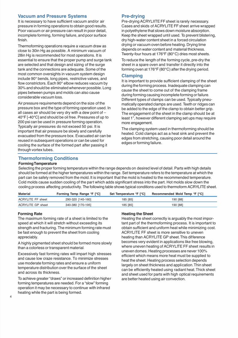
7/23/2019 Acrylite Fabrication Guide
http://slidepdf.com/reader/full/acrylite-fabrication-guide 48/66
4
Vacuum and Pressure SystemsIt is necessary to have sufficient vacuum and/or airpressure in forming operations to obtain good results.Poor vacuum or air pressure can result in poor detail,incomplete forming, forming failure, and poor surfacefinish.
Thermoforming operations require a vacuum draw asclose to 30in Hg as possible. A minimum vacuum of28in Hg is recommended for most operations. It is
essential to ensure that the proper pump and surge tankare selected and that design and sizing of the surgetank and the connections are adequate. Some of themost common oversights in vacuum system designinclude 90° bends, long pipes, restrictive valves, andflow constrictors. Each 90° elbow reduces vacuum by30% and should be eliminated whenever possible. Longpipes between pumps and molds can also causeconsiderable vacuum loss.
Air pressure requirements depend on the size of thepressure box and the type of forming operation used. Inall cases air should be very dry with a dew point of –
40°F [-40°C] and should be oil free. Pressures of up to200 psi can be used in pressure forming operation.Typically air pressures do not exceed 50 psi. It isimportant that air pressure be slowly and carefullyevacuated from the pressure box. Evacuated air can bereused in subsequent operations or can be used forcooling the surface of the formed part after passing itthrough vortex tubes.
Forming Rate
The maximum forming rate of a sheet is limited to thespeed at which it will stretch without exceeding itsstrength and fracturing. The minimum forming rate mustbe fast enough to prevent the sheet from cooling
appreciably.A highly pigmented sheet should be formed more slowlythan a colorless or transparent material.
Excessively fast forming rates will impart high stressesand cause low craze resistance. To minimize stressesuse moderate forming rates and ensure a uniformtemperature distribution over the surface of the sheetand across its thickness.
To achieve greater “draws” or increased definition higherforming temperatures are needed. For a “slow” formingoperation it may be necessary to continue with infraredheating while the part is being formed.
Material Forming Temp Range °F [°C] Set Temperature °F [°C] Recommended Mold Temp °F [°C]
ACRYLITE FF sheet 290-320 [145-160] 185 [85] 190 [88]
ACRYLITE GP sheet 340-380 [170-195] 185 [85] 190 [88]
Pre-dryingPre-drying ACRYLIITE FF sheet is rarely necessary.Cases and skids of ACRYLITE FF sheet arrive wrappedin polyethylene that slows down moisture absorption.Keep the sheet wrapped until used. To prevent blistering,dry high-water content sheet in a forced circulationdrying or vacuum oven before heating. Drying timedepends on water content and material thickness.Twenty-four hours at 176°F (80°C) dries most sheets.
To reduce the length of the forming cycle, pre-dry thesheet in a spare oven and transfer it directly into theforming oven at 176°F (80°C) after the drying period.
ClampingIt is important to provide sufficient clamping of the sheetduring the forming process. Inadequate clamping cancause the sheet to come out of the clamping frameduring forming causing incomplete forming or failure.Different types of clamps can be used. Typically pneu-matically operated clamps are used. Teeth or ridges canbe added to the edge of the clamp to obtain better grip.The engagement of the sheet in the clamp should be at
least 1”, however different clamping set ups may requiremore engagement.
The clamping system used in thermoforming should beheated. Cold clamps act as a heat sink and prevent theedges from stretching, causing poor detail around theedges or forming failure.
Thermoforming ConditionsForming Temperature
Selecting the proper forming temperature within the range depends on desired level of detail. Parts with high detailsshould be formed at the higher temperatures within the range. Set temperature refers to the temperature at which the
part can be safely removed from the mold. It is important that the mold is heated to the recommended temperature.Cold molds cause sudden cooling of the part which adds significant stress into the part. Hot molds slow down thecooling process affecting productivity. The following table shows typical conditions used to thermoform ACRYLITE sheet.
Heating the Sheet
Heating the sheet correctly is arguably the most impor-tant part of the thermoforming process. It is important toobtain sufficient and uniform heat while minimizing cost.ACRYLITE FF sheet is more sensitive to uneven
heating than ACRYLITE GP sheet. This differencebecomes very evident in applications like free blowing,where uneven heating of ACRYLITE FF sheet results inuneven domes. Heating processes are never 100%efficient which means more heat must be supplied toheat the sheet. Heating process selection dependslargely on sheet thickness and application. Thin sheetcan be efficiently heated using radiant heat. Thick sheetand sheet used for parts with high optical requirementsare better heated using air convection.
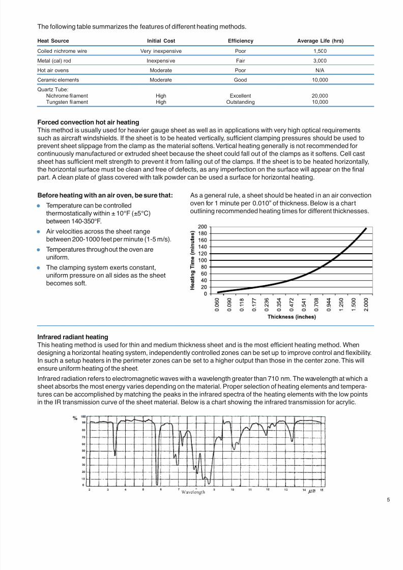
7/23/2019 Acrylite Fabrication Guide
http://slidepdf.com/reader/full/acrylite-fabrication-guide 49/66
Heat Source Initial Cost Efficiency Average Life (hrs)
Coiled nichrome wire Very inexpensive Poor 1,500
Metal (cal) rod Inexpensive Fair 3,000
Hot air ovens Moderate Poor N/A
Ceramic elements Moderate Good 10,000
Quartz Tube:
Nichrome filament High Excellent 20,000
Tungsten filament High Outstanding 10,000
Forced convection hot air heating
This method is usually used for heavier gauge sheet as well as in applications with very high optical requirementssuch as aircraft windshields. If the sheet is to be heated vertically, sufficient clamping pressures should be used toprevent sheet slippage from the clamp as the material softens. Vertical heating generally is not recommended forcontinuously manufactured or extruded sheet because the sheet could fall out of the clamps as it softens. Cell castsheet has sufficient melt strength to prevent it from falling out of the clamps. If the sheet is to be heated horizontally,the horizontal surface must be clean and free of defects, as any imperfection on the surface will appear on the finalpart. A clean plate of glass covered with talk powder can be used a surface for horizontal heating.
Infrared radiant heating
This heating method is used for thin and medium thickness sheet and is the most efficient heating method. Whendesigning a horizontal heating system, independently controlled zones can be set up to improve control and flexibility.In such a setup heaters in the perimeter zones can be set to a higher output than those in the center zone. This willensure uniform heating of the sheet.
Infrared radiation refers to electromagnetic waves with a wavelength greater than 710 nm. The wavelength at which asheet absorbs the most energy varies depending on the material. Proper selection of heating elements and tempera-tures can be accomplished by matching the peaks in the infrared spectra of the heating elements with the low pointsin the IR transmission curve of the sheet material. Below is a chart showing the infrared transmission for acrylic.
Before heating with an air oven, be sure that:
Temperature can be controlledthermostatically within ± 10°F (±5°C)between 140-350°F.
Air velocities across the sheet rangebetween 200-1000 feet per minute (1-5 m/s).
Temperatures throughout the oven areuniform.
The clamping system exerts constant,uniform pressure on all sides as the sheetbecomes soft.
As a general rule, a sheet should be heated in an air convectionoven for 1 minute per 0.010” of thickness. Below is a chartoutlining recommended heating times for different thicknesses.
%
The following table summarizes the features of different heating methods.
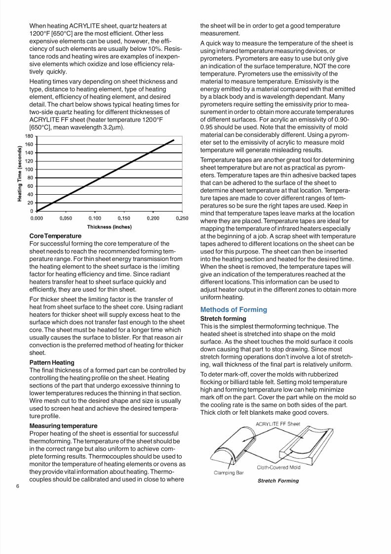
7/23/2019 Acrylite Fabrication Guide
http://slidepdf.com/reader/full/acrylite-fabrication-guide 50/66
6
When heating ACRYLITE sheet, quartz heaters at1200°F [650°C] are the most efficient. Other lessexpensive elements can be used, however, the effi-ciency of such elements are usually below 10%. Resis-tance rods and heating wires are examples of inexpen-sive elements which oxidize and lose efficiency rela-tively quickly.
Heating times vary depending on sheet thickness andtype, distance to heating element, type of heating
element, efficiency of heating element, and desireddetail. The chart below shows typical heating times fortwo-side quartz heating for different thicknesses ofACRYLITE FF sheet (heater temperature 1200°F[650°C], mean wavelength 3.2µm).
Core Temperature
For successful forming the core temperature of thesheet needs to reach the recommended forming tem-perature range. For thin sheet energy transmission fromthe heating element to the sheet surface is the limitingfactor for heating efficiency and time. Since radiantheaters transfer heat to sheet surface quickly and
efficiently, they are used for thin sheet.For thicker sheet the limiting factor is the transfer ofheat from sheet surface to the sheet core. Using radiantheaters for thicker sheet will supply excess heat to thesurface which does not transfer fast enough to the sheetcore. The sheet must be heated for a longer time whichusually causes the surface to blister. For that reason airconvection is the preferred method of heating for thickersheet.
Pattern Heating
The final thickness of a formed part can be controlled bycontrolling the heating profile on the sheet. Heating
sections of the part that undergo excessive thinning tolower temperatures reduces the thinning in that section.Wire mesh cut to the desired shape and size is usuallyused to screen heat and achieve the desired tempera-ture profile.
Measuring temperature
Proper heating of the sheet is essential for successfulthermoforming. The temperature of the sheet should bein the correct range but also uniform to achieve com-plete forming results. Thermocouples should be used tomonitor the temperature of heating elements or ovens asthey provide vital information about heating. Thermo-couples should be calibrated and used in close to where
the sheet will be in order to get a good temperaturemeasurement.
A quick way to measure the temperature of the sheet isusing infrared temperature measuring devices, orpyrometers. Pyrometers are easy to use but only givean indication of the surface temperature, NOT the coretemperature. Pyrometers use the emissivity of thematerial to measure temperature. Emissivity is theenergy emitted by a material compared with that emitted
by a black body and is wavelength dependant. Manypyrometers require setting the emissivity prior to mea-surement in order to obtain more accurate temperaturesof different surfaces. For acrylic an emissivity of 0.90-0.95 should be used. Note that the emissivity of moldmaterial can be considerably different. Using a pyrom-eter set to the emissivity of acrylic to measure moldtemperature will generate misleading results.
Temperature tapes are another great tool for determiningsheet temperature but are not as practical as pyrom-eters. Temperature tapes are thin adhesive backed tapesthat can be adhered to the surface of the sheet todetermine sheet temperature at that location. Tempera-ture tapes are made to cover different ranges of tem-peratures so be sure the right tapes are used. Keep inmind that temperature tapes leave marks at the locationwhere they are placed. Temperature tapes are ideal formapping the temperature of infrared heaters especiallyat the beginning of a job. A scrap sheet with temperaturetapes adhered to different locations on the sheet can beused for this purpose. The sheet can then be insertedinto the heating section and heated for the desired time.When the sheet is removed, the temperature tapes willgive an indication of the temperatures reached at thedifferent locations. This information can be used to
adjust heater output in the different zones to obtain moreuniform heating.
Methods of Forming
Stretch forming
This is the simplest thermoforming technique. Theheated sheet is stretched into shape on the moldsurface. As the sheet touches the mold surface it coolsdown causing that part to stop drawing. Since moststretch forming operations don’t involve a lot of stretch-ing, wall thickness of the final part is relatively uniform.
To deter mark-off, cover the molds with rubberizedflocking or billiard table felt. Setting mold temperature
high and forming temperature low can help minimizemark off on the part. Cover the part while on the mold sothe cooling rate is the same on both sides of the part.Thick cloth or felt blankets make good covers.
Stretch Forming
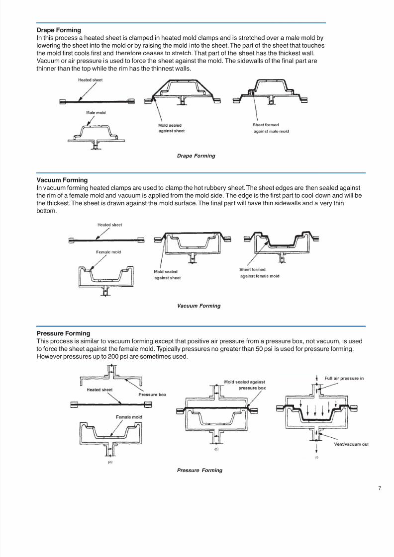
7/23/2019 Acrylite Fabrication Guide
http://slidepdf.com/reader/full/acrylite-fabrication-guide 51/66
Drape Forming
In this process a heated sheet is clamped in heated mold clamps and is stretched over a male mold bylowering the sheet into the mold or by raising the mold into the sheet. The part of the sheet that touchesthe mold first cools first and therefore ceases to stretch. That part of the sheet has the thickest wall.Vacuum or air pressure is used to force the sheet against the mold. The sidewalls of the final part arethinner than the top while the rim has the thinnest walls.
Vacuum Forming
In vacuum forming heated clamps are used to clamp the hot rubbery sheet. The sheet edges are then sealed against
the rim of a female mold and vacuum is applied from the mold side. The edge is the first part to cool down and will bethe thickest. The sheet is drawn against the mold surface. The final part will have thin sidewalls and a very thinbottom.
Pressure Forming
This process is similar to vacuum forming except that positive air pressure from a pressure box, not vacuum, is usedto force the sheet against the female mold. Typically pressures no greater than 50 psi is used for pressure forming.However pressures up to 200 psi are sometimes used.
Drape Forming
Vacuum Forming
Pressure Forming
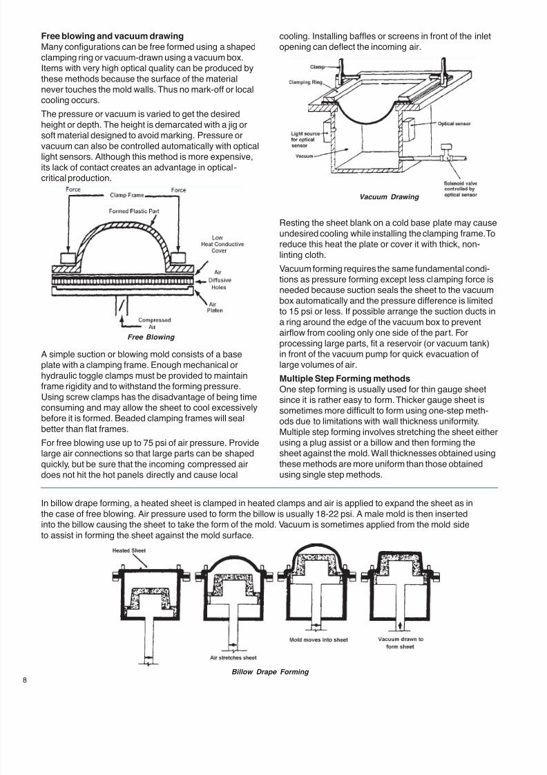
7/23/2019 Acrylite Fabrication Guide
http://slidepdf.com/reader/full/acrylite-fabrication-guide 52/66
8
Free blowing and vacuum drawing
Many configurations can be free formed using a shapedclamping ring or vacuum-drawn using a vacuum box.Items with very high optical quality can be produced bythese methods because the surface of the materialnever touches the mold walls. Thus no mark-off or localcooling occurs.
The pressure or vacuum is varied to get the desiredheight or depth. The height is demarcated with a jig or
soft material designed to avoid marking. Pressure orvacuum can also be controlled automatically with opticallight sensors. Although this method is more expensive,its lack of contact creates an advantage in optical-critical production.
A simple suction or blowing mold consists of a baseplate with a clamping frame. Enough mechanical orhydraulic toggle clamps must be provided to maintainframe rigidity and to withstand the forming pressure.Using screw clamps has the disadvantage of being time
consuming and may allow the sheet to cool excessivelybefore it is formed. Beaded clamping frames will sealbetter than flat frames.
For free blowing use up to 75 psi of air pressure. Providelarge air connections so that large parts can be shapedquickly, but be sure that the incoming compressed airdoes not hit the hot panels directly and cause local
Resting the sheet blank on a cold base plate may causeundesired cooling while installing the clamping frame. Toreduce this heat the plate or cover it with thick, non-linting cloth.
Vacuum forming requires the same fundamental condi-tions as pressure forming except less clamping force isneeded because suction seals the sheet to the vacuumbox automatically and the pressure difference is limitedto 15 psi or less. If possible arrange the suction ducts ina ring around the edge of the vacuum box to preventairflow from cooling only one side of the part. Forprocessing large parts, fit a reservoir (or vacuum tank)in front of the vacuum pump for quick evacuation oflarge volumes of air.
Multiple Step Forming methods
One step forming is usually used for thin gauge sheetsince it is rather easy to form. Thicker gauge sheet is
sometimes more difficult to form using one-step meth-ods due to limitations with wall thickness uniformity.Multiple step forming involves stretching the sheet eitherusing a plug assist or a billow and then forming thesheet against the mold. Wall thicknesses obtained usingthese methods are more uniform than those obtainedusing single step methods.
cooling. Installing baffles or screens in front of the inletopening can deflect the incoming air.
In billow drape forming, a heated sheet is clamped in heated clamps and air is applied to expand the sheet as inthe case of free blowing. Air pressure used to form the billow is usually 18-22 psi. A male mold is then insertedinto the billow causing the sheet to take the form of the mold. Vacuum is sometimes applied from the mold sideto assist in forming the sheet against the mold surface.
Free Blowing
Vacuum Drawing
Billow Drape Forming
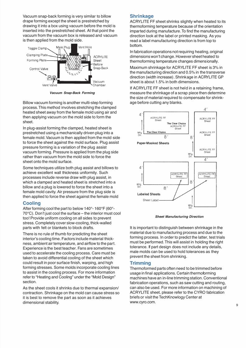
7/23/2019 Acrylite Fabrication Guide
http://slidepdf.com/reader/full/acrylite-fabrication-guide 53/66
Vacuum snap-back forming is very similar to billowdrape forming except the sheet is prestretched bydrawing it into a box using vacuum before the mold isinserted into the prestretched sheet. At that point thevacuum from the vacuum box is released and vacuumis then applied from the mold side.
Billow vacuum forming is another multi-step formingprocess. This method involves stretching the clampedheated sheet away from the female mold using air andthen applying vacuum on the mold side to form the
sheet.In plug-assist forming the clamped, heated sheet isprestretched using a mechanically driven plug into afemale mold. Vacuum is then applied from the mold sideto force the sheet against the mold surface. Plug assistpressure forming is a variation of the plug assistvacuum forming. Pressure is applied from the plug siderather than vacuum from the mold side to force thesheet onto the mold surface.
Some techniques utilize both plug assist and billows toachieve excellent wall thickness uniformity. Suchprocesses include reverse draw with plug assist, in
which a clamped and heated sheet is stretched into abillow and a plug is lowered to force the sheet into afemale mold cavity. Air pressure from the plug side isthen applied to force the sheet against the female mold
CoolingAfter forming cool the part to below 140°- 160°F (60°-70°C). Don’t just cool the surface – the interior must cooltoo! Provide uniform cooling on all sides to preventstress. Completely cover slow-cooling, thick-walledparts with felt or blankets to block drafts.
There is no rule of thumb for predicting the sheetinterior’s cooling time. Factors include material thick-
ness, ambient air temperature, and airflow to the part.Experience is the best teacher. Fans are sometimesused to accelerate the cooling process. Care must betaken to avoid differential cooling of the sheet whichcould result in poor surface finish, warping, and highforming stresses. Some molds incorporate cooling linesto assist in the cooling process. For more informationrefer to “Heating and Cooling” under the “Mold Design”section.
As the sheet cools it shrinks due to thermal expansion/ contraction. Shrinkage on the mold can cause stress soit is best to remove the part as soon as it achievesdimensional stability.
ShrinkageACRYLITE FF sheet shrinks slightly when heated to itsthermoforming temperature because of the orientationimparted during manufacture. To find the manufacturingdirection look at the label or printed masking. As youread a label manufacturing direction is from top tobottom.
In fabrication operations not requiring heating, originaldimensions won’t change. However sheet heated to
thermoforming temperature changes dimensionally.Maximum shrinkage for ACRYLITE FF sheet is 3% inthe manufacturing direction and 0.5% in the transversedirection (width increase). Shrinkage in ACRYLITE GPsheet is about 1.5% in both dimensions.
If ACRYLITE FF sheet is not held in a retaining frame,measure the shrinkage of a scrap piece then determinethe size of material required to compensate for shrink-age before cutting any blanks.
It is important to distinguish between shrinkage in thematerial due to manufacturing process and due to theforming process. In order to predict the latter, test trials
must be performed. This will assist in holding the righttolerance. If part design does not include any details,male molds can be used to hold tolerances as theyprevent the sheet from shrinking.
TrimmingThermoformed parts often need to be trimmed beforeusage in final applications. Certain thermoformingmachines have an in-line trimming station. Conventionalfabrication operations, such as saw cutting and routing,can also be used. For more information on machining ofACRYLITE sheet, please refer to the CYRO fabricationbriefs or visit the TechKnowlogy Center atwww.cyro.com.
Sheet Manufacturing Direction
Vacuum Snap-Back Forming
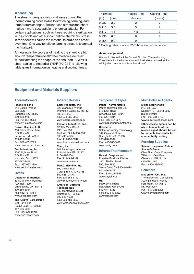
7/23/2019 Acrylite Fabrication Guide
http://slidepdf.com/reader/full/acrylite-fabrication-guide 54/66
10
AnnealingThe sheet undergoes various stresses during thethermoforming process due to stretching, forming, andtemperature changes. The induced stress in the sheetmakes it more susceptible to chemical attacks. Forcertain applications, such as those requiring sterilizationwith alcohols and other incompatible chemicals, stressin the sheet will cause the material to craze and crackover time. One way to relieve forming stress is to anneal
the final part.Annealing is the process of heating the sheet to a highenough temperature to allow for molecules to relaxwithout affecting the shape of the final part. ACRYLITEsheet can be annealed at 175°F [80°C]. The followingtable gives information on heating and cooling times.
Thickness Heating Time Cooling Time*
(in.) (mm) (hours) (hours)
0.080 2.0 2 2
0.118 3.0 3 2
0.117 4.5 4.5 2
0.236 6.0 6 2
0.354” 9.0 9 2
* Cooling rates of about 25°F/hour are recommended
Acknowledgement
We would like to thank McConnell Co., Inc. ThermoformingConsultants for the information and illustrations, as well as forediting the contents of this technical brief.
Thermoformers
Plastic Vac, Inc214 Dalton AvenueBox 5543Charlotte, NC 38225800-438-4139Fax: 704-334-0251www.pvi-plasticvac.com
Brown Machine LLC330 North Ross StreetP.O. Box 434Beaverton, MI 48612989-435-7741Fax: 989-435-2821www.brown-machine.com
Zed Industries, Inc.3580 Lightner RoadP.O. Box 458Vandalia, OH 45377937-667-8407Fax: 937-667-3340www.zedindustries.com
Ovens
Despatch Industries63 St. Anthony ParkwayP.O. Box 1320Minneapolis, MN 55418800-860-3944
Fax: 612-781-5454www.despatch.com
The Grieve Corporation500 Hart RoadRound Lake, IL 60073847-546-8225Fax: 847-546-9210www.grievecorp.com
Infrared Heaters
Solar Products, Inc.228 Wanaque AvenuePrompton Lakes, NJ 07442800-616-2601Fax: 973-835-7856www.solarproducts.com
Fostoria Industries, Inc.1200 N Main StreetP.O. Box 986Fostoria, OH 44830-0986800-495-4525Fax: 419-435-0842www.fostoriaindustries.com
Trent, Inc.201 Leverington AvenuePhiladelphia, PA 19127215-482-5000Fax: 215-482-9389www.trentheat.com
MAAC Machine, Inc.590 Tower Blvd.Carol Stream, IL 60188800-588-MAACFax: 630-665-7799www.maacmachinery.com
American CatalyticTechnologies
209 Montowese StreetBranford, CT 06405800-648-1698Fax: 203-483-6693www.americancatalytic.com
Temperature Tapes
Paper ThermometersPaper Thermometer Co.515 East RoadGreenfield, NH 03047603-547-2034Fax: 603-547-2073www.paperthermometer.com
CelsistripSolder Absorbing Technology144 Oakland StreetSpringfield, MA 01108800-628-8862Fax: 413-788-0490www.spirig.com
Infrared Thermometers
Raytek CorporationPortable Products Division1201 Shaffer Road,P.O. Box 1820Santa Cruz, CA 95061-1820800-866-5478Fax: 831-425-4561www.raytek.com
UEI8030 SW NimbusBeaverton, OR 97008503-644-8723
Fax: 503-643-6322www.ueitest.com
Mold Release Agents
Miller-StephensonP.O. Box 950Danbury, CT 06813-9982800-992-2424Fax: 203-791-8702www.miller-stephenson.com
Other release agents can beused. A sample of therelease agent should be sentto the technical center forcompatibility testing.
Forming Supplies
Sueded Neoprene RubberSuede-O-PreneOhio Flock-Cote Company7200 Northfield RoadCleveland, OH 44146440-439-1480Fax: 440-439-7413
Seminars
McConnell Co., Inc.Thermoforming Consultants3030 Sandage AvenueFort Worth, TX 76110817-926-8287Fax: 817-926-8298
www.thermoforming.com
Equipment and Materials Suppliers
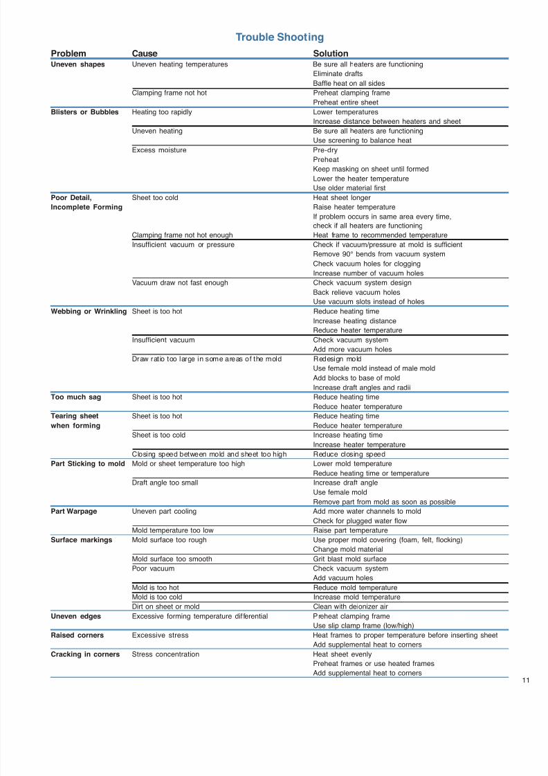
7/23/2019 Acrylite Fabrication Guide
http://slidepdf.com/reader/full/acrylite-fabrication-guide 55/66
Trouble Shooting
Problem Cause SolutionUneven shapes Uneven heating temperatures Be sure all heaters are functioning
Eliminate drafts
Baffle heat on all sides
Clamping frame not hot Preheat clamping frame
Preheat entire sheet
Blisters or Bubbles Heating too rapidly Lower temperatures
Increase distance between heaters and sheet
Uneven heating Be sure all heaters are functioning
Use screening to balance heat
Excess moisture Pre-dry
Preheat
Keep masking on sheet until formed
Lower the heater temperature
Use older material first
Poor Detail, Sheet too cold Heat sheet longer
Incomplete Forming Raise heater temperature
If problem occurs in same area every time,
check if all heaters are functioning
Clamping frame not hot enough Heat frame to recommended temperature
Insufficient vacuum or pressure Check if vacuum/pressure at mold is sufficient
Remove 90° bends from vacuum system
Check vacuum holes for clogging
Increase number of vacuum holesVacuum draw not fast enough Check vacuum system design
Back relieve vacuum holes
Use vacuum slots instead of holes
Webbing or Wrinkling Sheet is too hot Reduce heating time
Increase heating distance
Reduce heater temperature
Insufficient vacuum Check vacuum system
Add more vacuum holes
Draw ratio too large in some areas of the mold Redesign mold
Use female mold instead of male mold
Add blocks to base of mold
Increase draft angles and radii
Too much sag Sheet is too hot Reduce heating time
Reduce heater temperatureTearing sheet Sheet is too hot Reduce heating time
when forming Reduce heater temperature
Sheet is too cold Increase heating time
Increase heater temperature
Closing speed between mold and sheet too high Reduce closing speed
Part Sticking to mold Mold or sheet temperature too high Lower mold temperature
Reduce heating time or temperature
Draft angle too small Increase draft angle
Use female mold
Remove part from mold as soon as possible
Part Warpage Uneven part cooling Add more water channels to mold
Check for plugged water flow
Mold temperature too low Raise part temperature
Surface markings Mold surface too rough Use proper mold covering (foam, felt, flocking)
Change mold material
Mold surface too smooth Grit blast mold surface
Poor vacuum Check vacuum system
Add vacuum holes
Mold is too hot Reduce mold temperature
Mold is too cold Increase mold temperature
Dirt on sheet or mold Clean with deionizer air
Uneven edges Excessive forming temperature dif ferential Preheat clamping frame
Use slip clamp frame (low/high)
Raised corners Excessive stress Heat frames to proper temperature before inserting sheet
Add supplemental heat to corners
Cracking in corners Stress concentration Heat sheet evenly
Preheat frames or use heated frames
Add supplemental heat to corners
7/23/2019 Acrylite Fabrication Guide
http://slidepdf.com/reader/full/acrylite-fabrication-guide 56/66
12 1319(10E)-0603-10MG © 2003 CYRO Industries. All rights reserved. Printed in USA.
CYRO Industries, Parsippany, New Jersey 07054
Fire PrecautionsACRYLITE FF sheet is a combustible thermoplastic. Precautions should be taken to protect this material from flames and high heat sources. ACRYLITE FF sheetusually burns rapidly to completion if not extinguished. The products of combustion, if sufficient air is present, are carbon dioxide and water. However, in many firessufficient air will not be available and toxic carbon monoxide will be formed, as it will when other common combustible materials are burned. We urge good judgementin the use of this versatile material and recommend that building codes be followed carefully to assure it is used properly.
CompatibilityLike other plastic materials, ACRYLITE FF sheet is subject to crazing, cracking or discoloration if brought into contact with incompatible materials. These materialsmay include cleaners, polishes, adhesives, sealants, gasketing or packaging materials, cutting emulsions, etc. See the Tech Briefs in this ser ies for more informa-tion, or contact your ACRYLITE Sheet Distributor or the CYRO Technical Center for information on a specific product.
Important NoticeThe information and statements herein are believed to be reliable but are not to be construed as a warranty or representation for which we assume legal responsibility.Users should undertake sufficient verification and testing to determine the suitability for their own particular purpose of any information or products referred to herein.NO WARRANTY OF FITNESS FOR PARTICULAR PURPOSE IS MADE. Nothing herein is to be taken as permission, inducement or recommendation to practice anypatented invention without a license.
Web site: www.cyro.com
Additional Technical Informationand Assistance
We invite you to visit our TechKnowlogy Center
on www.cyro.com.
Visitors have immediate access to frequently askedquestions, technical concerns, physical properties,processing conditions, fabrication tips,
regulatory compliance information,engineering guidelines, tips fortroubleshooting, and hundredsof other facts about acrylicsfrom one of North America’sleading manufacturers ofacrylic-based polymer andsheet products. Sales Offices
For the name of your local Authorized Distributor,visit www.cyro.com, or call 800-631-5384.
Degussa
CYRO Industries379 Interpace ParkwayPO Box 677Parsippany, NJ 07054-0677
. .
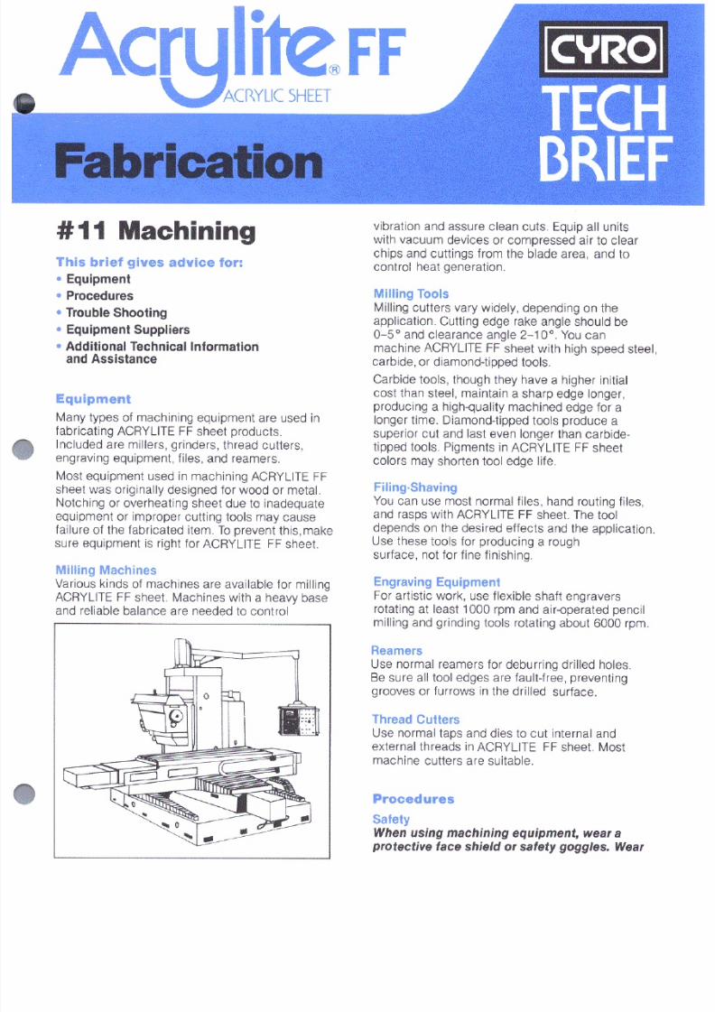
7/23/2019 Acrylite Fabrication Guide
http://slidepdf.com/reader/full/acrylite-fabrication-guide 57/66
7/23/2019 Acrylite Fabrication Guide
http://slidepdf.com/reader/full/acrylite-fabrication-guide 58/66

7/23/2019 Acrylite Fabrication Guide
http://slidepdf.com/reader/full/acrylite-fabrication-guide 59/66
7/23/2019 Acrylite Fabrication Guide
http://slidepdf.com/reader/full/acrylite-fabrication-guide 60/66
Degussa, CYRO Industries, 379 Interpace Parkway, PO Box 677, Parsippany, NJ 07054 800-631-5384www.cyro.com www.degussa.com
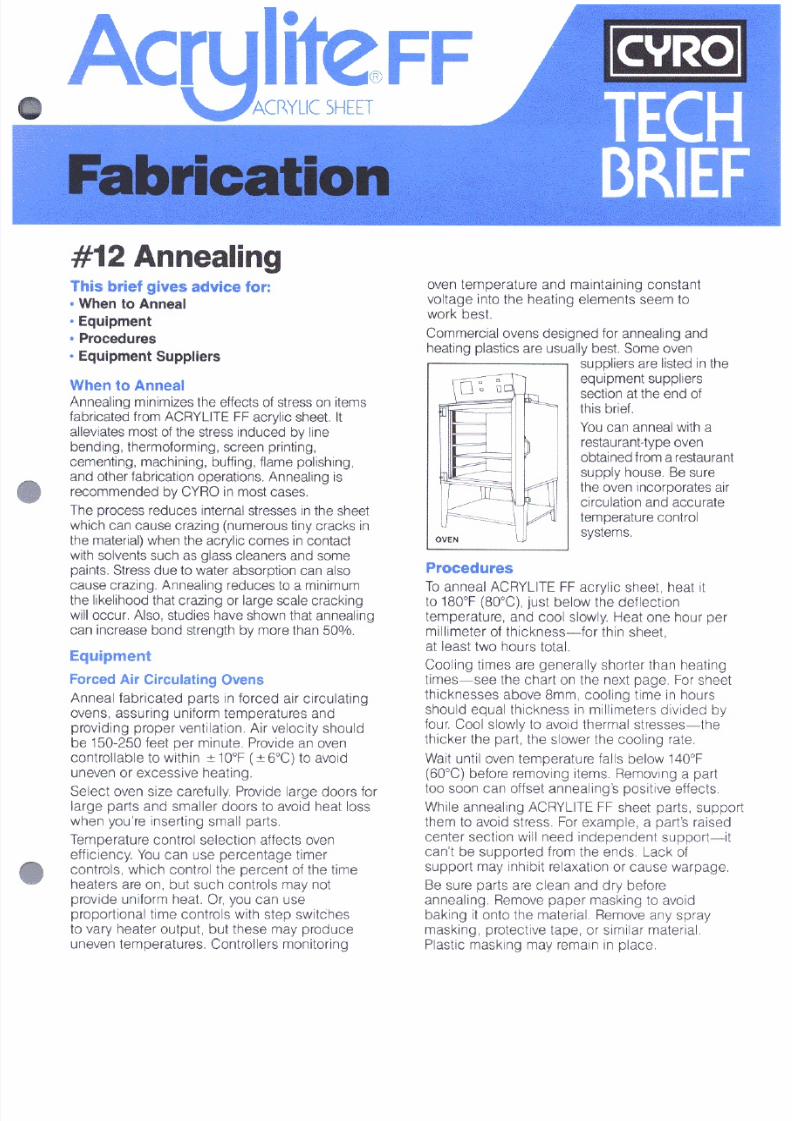
7/23/2019 Acrylite Fabrication Guide
http://slidepdf.com/reader/full/acrylite-fabrication-guide 61/66
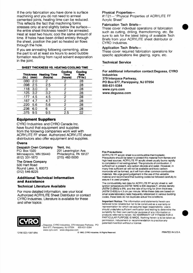
7/23/2019 Acrylite Fabrication Guide
http://slidepdf.com/reader/full/acrylite-fabrication-guide 62/66
For additional information contact:Degussa, CYROIndustries379 Interpace Parkway,PO Box 677, Parsippany, NJ 07054800-631-5384www.cyro.comwww.degussa.com
Degussa, CYRO Industries, 379 Interpace Parkway, POBox 677, Parsippany, NJ 07054 800-631-5384www.cyro.com www.degussa.com

7/23/2019 Acrylite Fabrication Guide
http://slidepdf.com/reader/full/acrylite-fabrication-guide 63/66
Fabrication
#13 Laser MachiningThis brief gives advice for:
Equipment
Procedures
Trouble Shooting Equipment Suppliers
Additional Technical Informationand Assistance
TECH
BRIEF
Equipment
CO2 lasers, used in appropriate applications, are power-ful and cost effective tools for cutting ACRYLITE® FFacrylic sheet. Small complex parts with clean, sharpinside corners, and parts of any size which requirecutting tolerances of less than 0.005”/ft. can be cut witha laser and left with a polished edge finish. Becauselaser-cutting offers a narrow kerf (0.010-0.020”), tremen-dous shape and size capability, as well as a cleanpolished, dust free cut, it is the premier choice for manyquality applications.
The Design of a CO2Laser
CO2
lasers work by emitting a beam of parallel light thathas a wavelength of 10.6 micron. This wavelength oflight is absorbed well by non-metals. When the beam of
light or energy is focused through a lens to a very smallpoint, it vaporizes the material in its path. This focusedlaser beam can be held stationary over an xy-axespositioning table or it can be positioned over a stationarysurface using a “flying head” configuration. A flying headset-up means that the laser beam moves over the workon one or two axes through the use of mirrors andmechanical positioning equipment. The controllers, PC’sand software used to control the positioning of the laserand the work are very similar to the hardware andsoftware used with other CNC machining equipment.This makes designing for and using the laser cutter nomore difficult than working with any other CNC machine.
Procedures
Setting Up To Cut ACRYLITE FF SheetThere are three basic variables involved when cuttingwith a laser, each affecting the quality of the cut and theresultant level of stress in the material being cut: thepower of the laser, the feed rate, and the pulse rate.
These can all be adjusted to allow for different material,material thicknesses and edge finishes. To cutACRYLITE FF sheet, a laser as small as 40 watts canbe used for thicknesses up to approximately ¼”. To getgood edge quality with a small laser, however, you mustslow the feed rate to approximately 20 inches/minute.For thicker sheet or faster feed rates, a larger laser isneeded. A 180-watt laser will provide fast economicalcutting of most thicknesses of acrylic sheet using onlyabout 75% power. Laser machines with higher wattage,500 to 1000 watts, permit higher feed rates and cuttingwith multiple heads at one time.
† Data taken from “Laser Processing of Plastic Sheet” by TimChristopherson, Plastics Fabricating & Forming, September/ October 2000.
7/23/2019 Acrylite Fabrication Guide
http://slidepdf.com/reader/full/acrylite-fabrication-guide 64/66
2
Trouble Shooting
Increasing the power of the laser at a given feed rateusually will result in a more glossy finish, but it alsoincreases the level of stress in the edge of the sheet.A faster feed rate with a more rapid pulse rate willgenerally result in an edge with lower stress but a less
glossy surface.
The pulse rate of a laser (measured in pulses persecond – pps) is the rate at which a laser “fires”. Thebeam of the laser is actually a series of small bursts orpulses, not a continuous stream. The pulse rate can becontrolled in two ways: proportionally to time or propor-tionally to distance traveled. While the pulse rateproportional to time method is more common and easierto program initially, this method usually results in burnedinside corners. The xy-controller takes longer to make acorner than a straight line so the corners (particularly theinside corners) absorb too much energy and tend to melt
and become over-stressed. This is an important consid-eration when cutting notch sensitive materials likeacrylic and polycarbonate. Inside corners are alwaysweak, high load areas. Everything possible should bedone to reduce stress or notches in these areas. Mak-ing the pulse rate proportional to the distance traveledeliminates much of this problem. As the controller slowsthe feed rate at the corners, the pulse rate slows down,keeping constant the amount of energy emitted at agiven point on the cut.
Important Considerations When Cutting
ACRYLITE FF SheetNo matter how sophisticated the controller or how fastthe feed rate, edge stress will always be a considerationin certain applications. Any time a sheet of acrylic orpolycarbonate is heated, the possibility of heat stressexists. This problem is greatest when only part of thesheet is heated, which is the case with laser cutting.The interface on the non-heated body of the sheet andthe rapidly heated, rapidly cooled edge of the laser cutsheet is susceptible to crazing. These highly stressedareas extend approximately 0.010-0.050” (depending onthickness) into the sheet. They are very susceptible tocrazing from contact with incompatible solvents or from
high mechanical stress, for instance, due to bending.
Adjusting the feed rate, pulse rate, and power canminimize the edge stress problem. Lower power and aslow pulse rate, combined with a relatively rapid feedrate, reduces the amount of energy or heat which isabsorbed by the sheet. Thereby, reducing both theamount of stress and the distance that the stressextends into the sheet. These conditions, however, will
result in a less glossy edge finish. In some circum-stances, it may be practical to scrape or machine awaythe stressed areas.
Gas Assist And Vacuum Table
Most high-powered lasers come equipped with a vacuumhold-down table and a gas assist stream. The type of
gas used, the flow rate of the gas assist stream, as wellas the efficiency of the vacuum table in removingvapors can influence the quality of the laser cut that isachieved. Good gas flow across the laser cut combinedwith an effective vacuum will help to remove vaporswhich can damage the work piece, result in small flamesand charring, or leave behind unwanted residues.
Laser Cuttable MaskingMasking performance is an important considerationwhen selecting acrylic sheet for your application. Ifmasking does not adhere well, parts can be damagedor scratched during fabrication and the efficiency of the
fabrication process itself can be reduced. At othertimes, masking can be difficult to remove resulting inextra labor and cost. The proper choice of masking foreach type of fabrication process can help to minimizeproblems.
Traditionally, paper masking has been the masking ofchoice for laser cutting. It will not fuse to the acrylic atthe edges of the laser cut sheet. Its strong consistentadhesion will prevent the masking from lifting whilehandling and laser cutting, protecting the acrylic sheet’ssurface from the hot, corrosive gases generated by thelaser. Laser cuttable polyethylene masking is now
available on acrylic sheet.
For maximum laser cutting efficiency and output, aspecially formulated light adhesive polyethylene mask-ing can be used. This masking removes very easilyfrom a laser cut part, yet offers sufficient adhesion towithstand most ordinary handling. Although it is rarely aproblem, this type of masking may lift in areas wherethe laser is prone to idle for excess periods of time dueto the masking’s light adhesive formula. This can occurat the beginning of a laser cut or when making a verytight radius cut. Lifting is easily prevented by using a“lead in” at the beginning of the laser cut and by reducing
the pulse rate or power when tight radius bends arenegotiated.
For a pristine, polished edge, a specially formulated non-adhesive polyethylene masking is available. Becauseall adhesive-based maskings will leave some residue ona laser cut edge, they can slightly reduce the polishedappearance of the laser cut edge. For applicationsdemanding the very highest appearance polished edge,
7/23/2019 Acrylite Fabrication Guide
http://slidepdf.com/reader/full/acrylite-fabrication-guide 65/66
a non-adhesive “laser cuttable” masking is recom-mended. This type of masking may be a little moredifficult to remove from the laser cut part than anadhesive based masking, but will provide a slightlyhigher quality polished edge. It is also slightly moreresistant to edge lift. If lift does occur, similar steps canbe taken as those described above.
Another consideration with regards to masking iswrinkles. In order to retain the original optics of thesheet being cut, the masking, particularly the maskingon the top of the piece, must be wrinkle-free. If themasking is not in contact with the sheet at the point ofthe cut, the hot laser gases will be trapped between themasking and the sheet, etching the surface. Etching isoften not a problem on the bottom of the sheet becausemost xy-tables use a vacuum hold down system. Thevacuum effectively removes the hot gases from thebottom of the sheet before they can cause any damage.
MaintenanceLike all sophisticated equipment, laser cutters requireregular maintenance for optimum performance. It is agood practice to note the power setting required to cut agiven thickness of material at a specific cutting speed.Over time, the power setting must be raised or cuttingspeeds reduced, due to the laser optics becoming dirtyand out of focus. As this occurs cut quality will alsodegrade. Regular maintenance by a qualified technicianwill help maintain cutting efficiency and quality.
Safety
While lasers are high-powered sophisticated tools, they
are no more or less dangerous than any other piece ofshop equipment when properly installed and operated.Standard safety glasses are often all that is necessaryfor eye protection. However, not all standard safetyglass is opaque to 10.6-micron light (i.e., optical densityof 5 at 10,600 nanometers), common to some lasers.ANSI Standard Z136.1 states that safety eyewear mustbe labeled with the wavelength and optical densityprotection factor. An exhaust system is needed toremove the potentially harmful vapors produced whenthe material is cut. Depending on the material cut, it maybe necessary to filter the vapors before exhausting themoutside. As with any other piece of equipment, proper
knowledge of operating and safety procedures is neces-sary before using a laser cutting system.
Emissions
A number of scientific investigations have been per-formed by various researchers to determine the amountand type of emissions that result from laser cuttingacrylic. Despite these efforts, it is impossible to predictthe exact by-products and their concentrations in theemission gases generated by laser cutting acrylic.
These depend upon the laser parameters, processingparameters, cover gases, exhaust method, and exactcomposition of the acrylic polymer. Additionally, thesestudies do not include the effects of the protective paperor polyethylene masking provided on acrylic sheet, nordo they include the possible impact of coatings.
When laser cutting acrylic, most of the decomposedacrylic is converted into its constituent monomers. Intypical ACRYLITE® acrylic sheet, these monomersinclude over 90% methylmethacrylate and the remain-der, methacrylate. Many suppliers of acrylic alsoemploy ethylacrylate in their acrylic formulations.(Ethylacrylate is included by the National ToxicityProgram in its list of substances that may be anticipatedto be carcinogens. The International Agency for Re-search on Cancer lists ethyl acrylate as a probablecarcinogen.)
During independent scientific research, Heferkamp,
Goede, Engel, and Wittbecker found that of the plasticsthey tested, acrylic resulted in the lowest aerosolgeneration (<10 mg/m3). Their work also indicated thatover 90% of the emissions from laser cutting acrylicwere gaseous methylmethacrylate monomer.
Troughton, Sims, Ellwood and Taylor found, in additionto methylmethacrylate monomer, small amounts oftoluene, methy-2-methyl-3-pentenoate, xylene, trimethylbenzene and alkanes. They found no PAH’s which wascontrary to the earlier findings of Ball, Kulik and Tan.
For more information see the references listed
below. CYRO Industries recommends installing ad-
equate ventilation equipment to ensure employeeexposures are below regulated levels. Considerationshould be given to environmental regulations if exhaust-ing the gases outside. Manufacturers of laser cuttingequipment can provide guidance on the collection andhandling of laser emissions.
SourcesH. Haferkamp, M. Goede, K. Engel and J. S. Wittbecker,“Hazardous Emissions: Characterization of CO2 LaserMaterial Processing,” Journal of Laser Applications,1995, 83-88, 7.
John M. Kokosa, “Hazardous Chemicals Produced byLaser Materials Processing,” Journal of Laser Applica-tions, 1994, 195-201, 6.
Mike Troughton, Jake Sims, Peter Ellwood and HelenTaylor, “Fume Emissions From Laser Cutting and HotGas Welding of Plastics.”
“Cutting Without Emission,” Industrial Laser Review,Sept. 1995, 159.
7/23/2019 Acrylite Fabrication Guide
http://slidepdf.com/reader/full/acrylite-fabrication-guide 66/66
Additional Technical Informationand Assistance
We invite you to visit our TechKnowlogy Centeron www.cyro.com.
Visitors have immediate access to frequently asked
questions, technical concerns, physical properties,
processing conditions, fabrication tips, regulatory
compliance information, engineering guidelines, tips
for troubleshooting, and hundreds of other facts about
acrylics from one of North America’s leading
manufacturers of acrylic-based
polymer and sheet products.
Fire Precautions
ACRYLITE FF sheet is a combustible thermoplastic. Precautions should be
taken to protect this material from flames and high heat sources. ACRYLITE FF
sheet usually burns rapidly to completion if not extinguished. The products of
combustion, if sufficient air is present, are carbon dioxide and water. However,
in many fires sufficient air will not be available and toxic carbon monoxide will
be formed, as it will when other common combustible materials are burned. We
urge good judgement in the use of this versatile material and recommend that
building codes be followed carefully to assure it is used properly.
Compatibility
Like other plastic materials, ACRYLITE FF sheet is subject to crazing, cracking
or discoloration if brought into contact with incompatible materials. These
materials may include cleaners, polishes, adhesives, sealants, gasketing or
packaging materials, cutting emulsions, etc. See the Tech Briefs in this series
for more information or contact your ACRYLITE Sheet Distributor or the CYRO
CYRO IndustriesFor more information or specific questions about
your project, contact your Authorized Distributor,
call 800-631-5384 or visit: www.cyro.com
Equipment and Materials Suppliers
The suppliers listed below offer materials and equipment
suitable for use with ACRYLITE FF sheet. Authorized
ACRYLITE Sheet Distributors may also offer materials
and equipment.
Laser Machining, Inc.
500 Laser Drive
Somerset, WI 54025
715-247-3285
Fax: 715-247-5650
www.lasermachining.com
TSI Lumonics Corp.
8401 Jefferson Hwy.
Maple Grove, MN 55369
763-315-1780
Fax: 763-315-1781
www.tsilumonics.com
Universal Laser Systems, Inc.
16008 N. 81st Street
Scottsdale, AZ 85260
480-483-1214
Fax: 480-483-5620
www.ulsinc.com
Curbell Plastics is a proud supplier of Acrylite® materials
Nationwide1.888.CURBELL
www.curbellplastics.com


![working with ACRYLITE 1084M - San Diego Plastics Inc.1].pdf · Dip or soak cementing ..... 20 Viscous cementing ..... 21 Glazing with ACRYLITE acrylic sheet ..... 22. ACRYLITE acrylic](https://static.fdocuments.net/doc/165x107/5a75f5907f8b9a63638ce602/working-with-acrylite-1084m-san-diego-plastics-inc-1pdfaa-dip-or-soak.jpg)