ACR CT Accreditation Program Testing Instructions/media/ACRAccreditation/... · American College of...
35
American College of Radiology CT Accreditation Program Testing Instructions (Revised January 6, 2017) This guide provides all of the instructions necessary for clinical tests, phantom tests and general submission for the ACR CT Accreditation Program. For assistance, contact the ACR Monday through Friday 8:30 am to 5:00 pm (ET). Telephone: 800-770-0145 Email: [email protected]
-
Upload
phungkhanh -
Category
Documents
-
view
220 -
download
0
Transcript of ACR CT Accreditation Program Testing Instructions/media/ACRAccreditation/... · American College of...

American College of Radiology CT Accreditation Program
Testing Instructions (Revised January 6, 2017)
This guide provides all of the instructions necessary for clinical tests, phantom tests and general submission for the ACR CT Accreditation
Program.
For assistance, contact the ACR Monday through Friday 8:30 am to 5:00 pm (ET). Telephone: 800-770-0145 Email: [email protected]

This document is copyright protected by the American College of Radiology. Any attempt to reproduce, copy, modify, alter or otherwise change or use this document without the express written permission of the American College of Radiology is prohibited.
Page 1 of 34 Return to Table of Contents Revised: 1/30/18
Table of Contents I. Revisions .............................................................................................................................................. 2 II. General Instructions ............................................................................................................................ 3
A. Introduction ...................................................................................................................................... 3 B. Online Application ........................................................................................................................... 3 C. Materials Due Date .......................................................................................................................... 4 D. Image Collection Time Period for Phantom and Clinical Images ................................................... 4
III. Annual System Performance Evaluation and Quality Control Testing ........................................... 5 IV. Clinical Testing Instructions ............................................................................................................ 6
A. Evaluate Your Facility’s Protocols .................................................................................................. 6 B. Select Images for Submission .......................................................................................................... 6
V. Clinical Image Quality Guide .............................................................................................................. 7 A. CT Clinical Evaluation Categories .................................................................................................. 7 B. Categories A and B: Technique Parameters and Anatomic Coverage – Adult Modules ................. 7
1. Adult Head/Neck Module ......................................................................................................... 8 2. Adult Chest Module .................................................................................................................. 9 3. Adult Abdomen Module ......................................................................................................... 10 4. Adult Cardiac Module ............................................................................................................. 11
C. Categories A and B: Technique Parameters and Anatomic Coverage – Pediatric Modules (0 – 18 years) ...................................................................................................................................................... 11
1. Pediatric Head/Neck Module .................................................................................................. 12 2. Pediatric Chest Module ........................................................................................................... 13 3. Pediatric Abdomen Module .................................................................................................... 13 4. Pediatric Cardiac Module ........................................................................................................ 13
D. Category C: Artifacts ..................................................................................................................... 14 E. Category D: Exam Identification ................................................................................................... 14 F. Category E: Examination Protocol ................................................................................................ 14 G. Prepare Clinical Images for Submission ........................................................................................ 15
VI. CT Phantom Testing Instructions .................................................................................................. 17 A. Introduction .................................................................................................................................... 17 B. The ACR Phantom ......................................................................................................................... 18 C. ACR Phantom Scanning Instructions ............................................................................................ 20
1. Fill Out the Phantom Data Form ............................................................................................. 20 2. Calibrate the Scanner .............................................................................................................. 21 3. Perform Phantom and Scanner Alignment .............................................................................. 21 4. Scan the Gammex 464 Phantom with your Facility’s Protocols ............................................. 23 5. Evaluate Your Phantom Images .............................................................................................. 23
D. Radiation Dosimetry ...................................................................................................................... 26 E. Phantom Scoring ............................................................................................................................ 29 F. Prepare Phantom Images for Submission ...................................................................................... 31
VII. Submitting and Labeling All Material ........................................................................................... 32 VIII. Mailing Instructions ....................................................................................................................... 33 IX. CT Accreditation Checklist ............................................................................................................ 34
A. Electronic Submissions .................................................................................................................. 34 B. CD Submissions ............................................................................................................................. 34

This document is copyright protected by the American College of Radiology. Any attempt to reproduce, copy, modify, alter or otherwise change or use this document without the express written permission of the American College of Radiology is prohibited.
Page 2 of 34 Return to Table of Contents Revised: 1/30/18
I. Revisions Date Page(s) Section Description of Revisions
7/9/15 All All Combined the clinical testing instructions, phantom testing instructions and clinical image quality guide into one document.
7/9/15 8 – 15 Clinical Image Quality Guide
Simplified the Clinical Image Quality Guide portion by specifying only the minimum requirements for accreditation submission.
7/9/15 30 CT Phantom Testing Instructions
Listed major and minor deficiencies associated with phantom submissions.
11/30/16 26 CT Phantom Testing Instructions
Added pediatric abdomen dose reference values and pass/fail criteria based on 32 cm phantom
11/30/16 27 CT Phantom Testing Instructions
Added instructions for scanning the pediatric abdomen dose with a 32 cm phantom (if applicable)
11/30/16 28-29 CT Phantom Testing Instructions
Added CTDIvol as reported by scanner, percent difference between calculated CTDIvol and CTDIvol reported by scanner, dose notification values for XR-29 compliance (if applicable), and SSDE (for adult and pediatric abdomen protocols) to the list of items available in the dose calculation forms.
11/30/16 29-30 CT Phantom Testing Instructions
Added major and minor deficiencies associated with incorrect CTDvol calculations
1/06/17 30 CT Phantom Testing Instructions
Added minor deficiency when CTDIvol exceeds the reference level
7/27/17 33 Mailing Instructions Strongly suggested mailing submission via traceable, signature required method due to HIPPA

This document is copyright protected by the American College of Radiology. Any attempt to reproduce, copy, modify, alter or otherwise change or use this document without the express written permission of the American College of Radiology is prohibited.
Page 3 of 34 Return to Table of Contents Revised: 1/30/18
II. General Instructions
A. Introduction Successful accreditation is a team effort involving the lead supervising physician, CT technologist and qualified medical physicist. It is important that each pertinent member of the team read and understand the documents listed below before beginning the CT Accreditation process:
• ACR CT Accreditation Program Requirements
• ACR CT Accreditation Testing Instructions to ensure that your facility’s protocols meet the revised requirements before continuing
The following items are available under Testing and QC forms on the CT Accreditation page of the ACR website:
1. Clinical Data Form
2. Phantom Data Form
3. Phantom Dose Forms
4. Phantom Order Form (Gammex)
5. Frequently Asked Questions (FAQs)
6. User Instructions for Electronic Submission of Images
Forms 1-3 are generic forms designed to assist you in gathering data. Do not submit these forms. You must log on to the ACR accreditation database ACRedit (https://acredit.acr.org) to enter the data in your online testing package and submit the package online. Print the completed forms from the database to include with your images if submitting by CD or film.
The following items will be sent to the site and are required if submitting by CD or film:
• Bar coded identification labels for all images and forms
Follow all instructions for every unit being reviewed for accreditation. Every unit must apply for all patient types and modules routinely performed on each unit for a facility to be accredited. Keep copies of all documents and images submitted to ACR for your records.
There are three portions to your ACR CT Accreditation submission:
1. Annual System Performance Evaluation Summary
2. Clinical Testing
3. Phantom Testing
You must utilize the services of a qualified medical physicist for the Annual System Performance Evaluation, oversight of your facility’s technologist quality control (QC) program and the dosimetry portion of your phantom testing. The ACR strongly recommends using the services of a qualified medical physicist for the image quality control portion of your phantom submission.
B. Online Application The application for ACR CT Accreditation is found online through the ACR website at https://acredit.acr.org. If your facility has never applied for accreditation before, you will “register” as a new facility. New facilities will be assigned a unique identification number

This document is copyright protected by the American College of Radiology. Any attempt to reproduce, copy, modify, alter or otherwise change or use this document without the express written permission of the American College of Radiology is prohibited.
Page 4 of 34 Return to Table of Contents Revised: 1/30/18
(CTAP #) after the online application is submitted. This number appears on all correspondence from the ACR, your online records and on all of the barcode labels (if submitting by CD or film). Please use this number on all submitted materials and to identify your facility when contacting the ACR for assistance.
Approximately eight months prior to the expiration of the CT Accreditation, the ACR will email an Accreditation Renewal Notice to the facility login user. The facility user should login to the online database (https://acredit.acr.org) and select the “start renewal” link no later than 6 months prior to expiration of your current accreditation to ensure that there are no gaps in your continuous accreditation that could affect your reimbursement.
After your application is processed, an online testing packet will be activated which will contain all of the clinical and phantom data forms required for accreditation review. Your facility will receive an email with a link to the online testing packet as well as a link to the electronic PDF version of the CT Quality Control Manual. Your facility user must log into the account and fill out all forms required in the online Testing Package. The testing packet must be submitted online and all completed forms must be printed from the database and mailed with the images if submitting by CD or film.
To achieve ACR CT accreditation, a CT unit must pass both the clinical and phantom image quality tests.
The ACR website (www.acr.org) provides a listing of accredited facilities and facilities that are under review. If a third party payer requests verification of your participation in one of the accreditation programs, please refer them to the ACR website accredited facility search.
C. Materials Due Date The online testing packet has the image submission due date. You must collect your test images and return them to the ACR by that date. Failure to meet this due date will jeopardize completion of your accreditation. Thus, if your facility is renewing its accreditation, we cannot guarantee completion in a timely fashion before your ACR certificate expires. If your site cannot submit the required materials by your due date, notify the ACR immediately.
D. Image Collection Time Period for Phantom and Clinical Images All examinations submitted must have been performed within 6 months of the date on the application. No images will be accepted for review that predates the application by more than six months.

This document is copyright protected by the American College of Radiology. Any attempt to reproduce, copy, modify, alter or otherwise change or use this document without the express written permission of the American College of Radiology is prohibited.
Page 5 of 34 Return to Table of Contents Revised: 1/30/18
III. Annual System Performance Evaluation and Quality Control Testing Medical physicists for all sites applying for accreditation or renewal must demonstrate compliance with the ACR requirements for quality control and Annual System Performance Evaluation or Acceptance Testing Evaluation (for new units) as outlined in the CT Quality Control Manual. These must be performed by a qualified medical physicist.
Additional routine QC testing by the radiologic technologist is also required. If you have been conducting QC for less than one quarter, you may perform QC testing every business day for two weeks to achieve baseline data and set up your action limits. Additionally, if the Annual System Performance Evaluation and/or weekly on-site QC data show performance deficits (e.g. problems with the system and/or data outside of the action limits), the facility must take steps to correct the problems and submit documentation of the corrective action with the image submission.
Submit the following:
1. Annual System Performance Evaluation Summary (to include evaluation of the technologist QC) signed by a qualified medical physicist. Your medical physicist must use the summary form provided by the ACR or one similar that itemizes the pass-fail results of all the same tests using the same names and order as is outlined on the ACR form.
2. Documentation of any corrective action taken if recommended in the Annual System Performance Evaluation (i.e. test failures or data outside of action limits).
The annual system performance evaluation summary form can be found on the website. http://www.acraccreditation.org/Modalities/CT If submitting by mail, staple all forms together, and place the annual system performance evaluation barcode label on the first page.

This document is copyright protected by the American College of Radiology. Any attempt to reproduce, copy, modify, alter or otherwise change or use this document without the express written permission of the American College of Radiology is prohibited.
Page 6 of 34 Return to Table of Contents Revised: 1/30/18
IV. Clinical Testing Instructions
A. Evaluate Your Facility’s Protocols With your supervising physician, ensure that all of your facility’s protocols meet the minimum requirements listed in the Clinical Image Quality Guide section of these instructions.
B. Select Images for Submission 1. Select examples of your best work and have them approved by your supervising
physician prior to submission. Your supervising physician should review all materials submitted for accreditation.
2. Submit localizer or scout sequences with all examinations with cross-reference locations.
3. The submission of examinations performed on models or volunteers is strictly prohibited and may jeopardize accreditation. In addition, images submitted for each individual examination must be from the same patient (i.e. all brain images must be from the same brain examination).

This document is copyright protected by the American College of Radiology. Any attempt to reproduce, copy, modify, alter or otherwise change or use this document without the express written permission of the American College of Radiology is prohibited.
Page 7 of 34 Return to Table of Contents Revised: 1/30/18
V. Clinical Image Quality Guide The requirements used by the accreditation reviewers represent a technical baseline for producing acceptable diagnostic examinations. Although some technical factors are specified and required, facilities should use their own exam protocols and submit their exam protocol along with the studies for evaluation. Examination protocols should apply the principle of minimizing radiation doses to as low as reasonably achievable (ALARA).
The ACR provides comprehensive practice parameters and technical standards for CT imaging which are independent of the accreditation program but provide guidance for compliance with the accreditation process. As needed, please visit the ACR website (http://www.acr.org/Quality-Safety/Standards-Guidelines) for a listing of practice parameters and technical standards.
Additional guidance and educational materials may be found at the following webpages:
• http://www.aapm.org/pubs/CTProtocols/
• http://imagewisely.org/
A. CT Clinical Evaluation Categories The categories for scoring examinations submitted for ACR CT Accreditation are:
A. Technique Parameters
B. Anatomic Coverage
C. Artifacts
D. Examination Identification: Missing Information
E. Examination Protocols
B. Categories A and B: Technique Parameters and Anatomic Coverage - Adult Modules Criteria for categories A and B are listed per examination in the tables below.
Important: All items in bold in the Technique Parameters and Anatomic Coverage sections below are required to successfully achieve accreditation. CTDIvol information is required for each study. Either include a screen save of the dose with the images, or enter the dose as displayed by the scanner in the Clinical Test Image Data Sheet.

This document is copyright protected by the American College of Radiology. Any attempt to reproduce, copy, modify, alter or otherwise change or use this document without the express written permission of the American College of Radiology is prohibited.
Page 8 of 34 Return to Table of Contents Revised: 1/30/18
1. Adult Head/Neck Module Adult Head
A. Technique Parameters Required series Unenhanced Reconstructed slice width ≤ 5 mm Reconstruction algorithm Standard or equivalent Scan FOV “Head” or equivalent CTDIvol Reference value: 75 mGy*
Pass/fail criteria: 80 mGy* B. Anatomical Coverage
Coverage Base of the skull to the vertex; Must include entire head with visualization of the entire bony cranium
Lens Exposure Lens exposure should be avoided Adult Temporal Bones
A. Technique Parameters Required series Axial and coronal; With multiple detector helical
scanners, coronal images may be reconstructed from axial images
Reconstructed slice width ≤ 2 mm Reconstruction algorithm Sharp or equivalent high spatial frequency Scan FOV “Head” or equivalent CTDIvol There are no reference values for this examination
B. Anatomical Coverage Coverage Axials: Mastoid tip through petrous bone
Coronals: Mandibular condyles through mastoid bone Display FOV 10 cm
Adult C-spine A. Technique Parameters
Required series Axial with sagittal and coronal reformations. Reconstructed slice width ≤ 3 mm Reconstruction algorithm Sharp (or equivalent) and smooth (or equivalent) CTDIvol There are no reference values for this examination
B. Anatomical Coverage Coverage Cranio-cervical junction to the T1 vertebrae Display FOV 14-16 cm

This document is copyright protected by the American College of Radiology. Any attempt to reproduce, copy, modify, alter or otherwise change or use this document without the express written permission of the American College of Radiology is prohibited.
Page 9 of 34 Return to Table of Contents Revised: 1/30/18
2. Adult Chest Module Adult Chest
A. Technique Parameters Required series IV contrast may be used but is not required Reconstructed slice width ≤ 5 mm Reconstructed algorithm Standard or equivalent CTDIvol Reference Value: 21 mGy*
Radiation dose reduction methods such as Automatic Exposure Control methods (e.g. Tube Current Modulation) are encouraged.
B. Anatomic Coverage Coverage Lung apex to below the lung bases
Adult Pulmonary Embolus A. Technique Parameters
Required series IV contrast enhanced Reconstructed slice width ≤ 3 mm Reconstructed algorithm Standard or equivalent CTDIvol There are no reference values for this examination
Radiation dose reduction methods such as Automatic Exposure Control methods (e.g. Tube Current Modulation) are encouraged.
B. Anatomic Coverage Coverage Lung apices through lung bases
Adult HRCT A. Technique Parameters
Required series Non-enhanced Reconstructed slice width ≤ 1.5 mm Reconstructed algorithm Sharp (Bone or equivalent high spatial frequency) Reconstruction spacing ≤ 10 mm (may be contiguous from helical scans or
spaced interval acquisition) CTDIvol There are no reference values for this examination
B. Anatomical Coverage Coverage Lung apices through lung bases
Adult Aortic Dissection A. Technique Parameters
Required series IV contrast enhanced Reconstructed slice width ≤ 3 mm Reconstruction algorithm Standard CTDIvol There are no reference values for this examination
B. Anatomical Coverage Coverage Lung apices through the level of the aortoiliac
bifurcation *National Council on Radiation Protection and Measurement Diagnostic. Reference levels and achievable doses in medical and dental imaging: recommendations for the United States. Bethesda, MD. NCRP Report #172; 2012. The 21 mGy reference value for the adult chest study is based on an average size patient and may be higher for larger sized patients.

This document is copyright protected by the American College of Radiology. Any attempt to reproduce, copy, modify, alter or otherwise change or use this document without the express written permission of the American College of Radiology is prohibited.
Page 10 of 34 Return to Table of Contents Revised: 1/30/18
3. Adult Abdomen Module Adult Abdomen
A. Technique Parameters Required series IV contrast enhanced. Should be timed to portal venous
phase. Reconstructed slice width ≤ 5 mm Reconstructed algorithm Standard or soft tissue (or appropriate body kernel) Oral contrast Oral contrast material must be present with barium or
neutral contrast agents CTDIvol Reference value: 25 mGy *
Pass/Fail criteria: 30 mGy * B. Anatomical Coverage
Coverage Diaphragm to iliac crest to include the entire liver; May include pelvis
Adult Liver Study A. Technique Parameters
Required series Non-contrast and IV contrast enhanced study to include arterial and portal venous phase series
Reconstructed slice width ≤ 3 mm Reconstructed algorithm Standard or soft tissue (or appropriate body kernel) Oral Contrast Not required CTDIvol There are no reference values for this examination
B. Anatomical Coverage Coverage Entire liver must be covered
Adult Renal Study*** A. Technique Parameters
Required series Non-contrast and IV contrast enhanced Reconstructed slice width ≤ 3 mm through the kidneys; The slice width should be
the same in all series Reconstructed algorithm Standard or soft tissue (or appropriate body kernel) Oral Contrast Not required CTDIvol There are no reference values for this examination.
B. Anatomical Coverage Coverage Must encompass the entire length of both kidneys
***This is not for renal stone evaluation or follow-up Adult Pancreas Study
A. Technique Parameters Required series Non-contrast and IV contrast enhanced Reconstructed slice width ≤ 3 mm Reconstructed algorithm Standard or soft tissue (or appropriate body kernel) Oral contrast Oral contrast material must be present with barium or
neutral contrast agents CTDIvol There are no reference values for this examination
B. Anatomical Coverage Coverage Must include entire pancreas
* CTDIvol is guidance based on a single series or uniphasic exam for a standard size patient.

This document is copyright protected by the American College of Radiology. Any attempt to reproduce, copy, modify, alter or otherwise change or use this document without the express written permission of the American College of Radiology is prohibited.
Page 11 of 34 Return to Table of Contents Revised: 1/30/18
4. Adult Cardiac Module Adult Coronary CTA
A. Technique Parameters Required series Best phase of contrast enhanced axial images* Dose reduction Required (dose modulation, prospective gating or
automatic dose reduction) Reconstructed slice width ≤ 1 mm Reconstruction algorithm Standard CTDIvol ≤ 50 mGy prospective gating
≤ 150 mGy retrospective gating CTDIvol information on dose received is required.
Gating The use of prospective gating is encouraged whenever possible.***
B. Anatomic Coverage Coverage** Scan must cover the entire coronary circulation
and heart** Required Screen Shots* CTDIvol and DLP
Scout with locations displayed Curved or straight reformat of 2 cm of LAD Curved or straight reformat of 2 cm of LCX Curved or straight reformat of 2 cm of OM1 or first large OM
* Only submit the one best phase set of axial images and the required screen shots. Additional cardiac phases, multiplanar views and reconstructions should not be submitted. ** Additional calcium score images are not recommended. Calcium score scans should not be used in patients with already known CAD. ***If retrospective gating is used, include justification in the “other symptoms, abnormal studies or pertinent information” section of the Clinical Test Image Datasheet.
C. Categories A and B: Technique Parameters and Anatomic Coverage - Pediatric Modules (0 – 18 years) Special attention must be paid to scanner output (CTDIvol) for pediatric studies. The facility will not receive a pass if the radiation dose is perceived to be too high, regardless of whether the rest of the CT study conforms to satisfactory criteria.
It is important for reviewers to be aware that there may be significant differences between the dose estimates reported by some CT scanners for pediatric scans based on which phantom size (16 or 32 cm diameter) is used to report the CTDIvol values in the dose report. Though the manufacturers are converging on a standard for pediatric abdomen exams being reported with the 32 cm (body) CTDI phantom only, there are still differences between manufacturers in the existing installed base of scanners. The difference between reporting dose to a 32 cm diameter phantom to that of a 16 cm diameter phantom for the same scanner output can be a factor of 2 to 2.5 (lower when the 32 cm phantom is used). Therefore, reviewers are asked to pay special attention to the phantom size used in reporting CTDIvol on the scanner for pediatric abdomens.
Criteria for categories A and B are listed per examination in the tables below.

This document is copyright protected by the American College of Radiology. Any attempt to reproduce, copy, modify, alter or otherwise change or use this document without the express written permission of the American College of Radiology is prohibited.
Page 12 of 34 Return to Table of Contents Revised: 1/30/18
1. Pediatric Head/Neck Module Pediatric Head
A. Technique Parameters Required series Non-enhanced Reconstructed slice width ≤ 5 mm Reconstruction algorithm Standard or equivalent Scan FOV “Head” or equivalent CTDIvol Reference value: 35 mGy*
Pass/fail criteria: 40 mGy* B. Anatomical Coverage
Coverage Base of the skull through the vertex Lens exposure Lens exposure should be avoided
Pediatric Sinus A. Technique Parameters
Required series Coronals-May be reconstructed from axial images Reconstructed slice width ≤ 3 mm from the frontal through the anterior ethmoid
sinuses ≤ 5 mm from the posterior ethmoid through the sphenoid sinuses
Reconstructed algorithm Detail or other high spatial frequency Scan FOV “Head” or equivalent CTDIvol There are no reference values for this examination
B. Anatomic Coverage Coverage Frontal through the ethmoid sinuses
Pediatric Temporal Bones A. Technique Parameters
Required series Axial and coronal images-Coronal images may be reconstructed from axial images
Reconstructed slice width ≤ 1.5 mm Reconstructed algorithm Edge or other high spatial frequency Scan FOV “Head” or equivalent CTDIvol There are no reference values for this examination
B. Anatomic Coverage Coverage Mastoid tip through petrous bone Display FOV 10 cm
Pediatric C-spine A. Technique Parameters
Required series Axial with sagittal and coronal reformations Reconstructed slice width ≤ 3 mm Reconstruction algorithm Bone CTDIvol There are no reference values for this examination
B. Anatomic Coverage Coverage Cranio-cervical junction to the T1 vertebrae Display FOV 9-14 cm
*CTDIvol values are based on a 1 year old age.
Important: All items in bold in the Technique Parameters and Anatomic Coverage sections below are required to successfully achieve accreditation. CTDIvol information is required for each study. Either include a screen save of the dose with the images, or enter the dose as displayed by the scanner in the Clinical Test Image Data Sheet.

This document is copyright protected by the American College of Radiology. Any attempt to reproduce, copy, modify, alter or otherwise change or use this document without the express written permission of the American College of Radiology is prohibited.
Page 13 of 34 Return to Table of Contents Revised: 1/30/18
2. Pediatric Chest Module Pediatric Chest
A. Technique Parameters Required Series Non-enhanced Reconstructed slice width ≤ 5 mm Reconstruction algorithm Standard or high spatial frequency CTDIvol There are no reference values for this examination
B. Anatomic Coverage Coverage Lung apex to below the lung bases
3. Pediatric Abdomen Module Pediatric Abdomen
A. Technique Parameters Required series IV contrast enhanced Reconstructed slice width ≤ 5 mm Reconstructed algorithm Standard or soft tissue (or appropriate body kernel) Oral contrast Oral contrast material must be present with barium or
neutral contrast agents CTDIvol Reference value: 15 mGy*
Pass/fail criteria: 20 mGy* B. Anatomic Coverage
Coverage Diaphragm through the iliac crest Pediatric Adrenal or Renal
A. Technique Parameters Required series IV contrast enhanced Reconstructed slice width ≤ 3 mm Reconstruction algorithm Standard or soft tissue (or appropriate body kernel) Oral contrast Not required CTDIvol There are no reference values for this examination
B. Anatomic Coverage Coverage Extend just above the diaphragm to the iliac crest or
inferior extent of the kidneys *As reported by the scanner using a 16 cm phantom. If scanner reports values using a 32 cm phantom, then approximate limits would be 7.5 mGy and 10 mGy. The CTDIvol is based on a 40-50 lb. patient size.
4. Pediatric Cardiac Module Pediatric Cardiac Exam such as for Congenital or Coronary Artery Disease
A. Technique Parameters Required series Single phase contrast enhanced (multiple phases
must be justified due to increase in radiation dose) Reconstructed slice width ≤ 1.5 mm Reconstruction algorithm Standard Dose reduction Required (dose modulation, prospective gating,
manual mA/kV manipulation or automatic dose reduction)*
CTDIvol There are no reference values for this examination B. Anatomic Coverage
Coverage Inlet to the diaphragm *Prospective gating is encouraged.

This document is copyright protected by the American College of Radiology. Any attempt to reproduce, copy, modify, alter or otherwise change or use this document without the express written permission of the American College of Radiology is prohibited.
Page 14 of 34 Return to Table of Contents Revised: 1/30/18
D. Category C: Artifacts • Excessive motion artifacts that result in indistinct or "double" contours to organs
should be repeated if they significantly degrade the examination quality.
• The submitted images should not exhibit excessive noise.
• Streak artifacts that compromises diagnostic quality with sections not repeated may be a deficiency. However, internal metallic surgical clips may cause minor streak artifact that will not be judged as deficient.
E. Category D: Exam Identification Patient and technical data must be displayed on the images or be readily accessible in the DICOM header. All patient information annotated on clinical examinations will be kept confidential by the ACR, as stated in the Practice Site Accreditation Survey Agreement.
1. Patient name (first and last)
2. Patient age (or date of birth)
3. Gender of patient, date of exam
4. Institution name
5. Left/right labeling
6. Technical parameters:
• kV
• mA (or mAs or effective mAs or mAs/slice, as reported by scanner)
• Rotation time
• Pitch (if available)
• Reconstructed image thickness (slice width)
• Reconstructed filter/kernel
• Display field of view (FOV)
7. Image number (numbered consecutively based on anatomic location)
8. Table position (scan location)
9. Presence or absence of IV contrast
10. Dose report
F. Category E: Examination Protocol Facilities are required to submit a copy of their scanning protocols with the images. The facility should submit its protocols in the format that it normally uses on site, but they need to be readily understandable by a reviewer charged with correlating those protocols with the submitted images. The ACR does not provide forms for the site’s protocols. These protocols must be submitted on paper (typed) with the provided label affixed to the protocol or uploaded if electronic submission is selected.
A typical protocol should at least include the following elements:
• Indication

This document is copyright protected by the American College of Radiology. Any attempt to reproduce, copy, modify, alter or otherwise change or use this document without the express written permission of the American College of Radiology is prohibited.
Page 15 of 34 Return to Table of Contents Revised: 1/30/18
• Scanner acquisition settings (routine kV, mA/mAs/effective mAs, collimation (N x T), pitch, rotation time, usage of radiation dose reduction methods (automatic exposure control such as tube current modulation, settings for dose reduction methods, etc.)
• Phase of respiration
• Reconstruction settings (reconstructed image width (slice thickness), reconstruction interval, reconstruction kernel/filter, reconstructed field of view (FOV))
• Anatomical coverage (i.e. lung apices to lung bases, top of diaphragm to iliac crest, etc.)
• IV contrast (with injection rate and scan delay), if applicable
• EKG gating (cardiac studies) policy
G. Prepare Clinical Images for Submission 1. Electronic submission of images
• If you selected electronic image submission in your online application, please follow the ACR Accreditation Electronic Submission Instructions at: http://www.acraccreditation.org/~/media/ACRAccreditation/Documents/General/ElectronicSubmissionofImages.pdf?la=en.
2. CD submission of images
a. The clinical images must be in DICOM format, burned on a 5¼ inch CD or DVD media. (3 inch discs are not acceptable)
b. Exams from separate units must be burned onto separate discs.
c. Each disc must contain all required exams. (It is understood that certain systems cannot burn multiple patient exams onto the same CD. In these instances, burn each exam to a separate CD). Two copies of each CD or DVD are required for each unit. Each exam should contain the following:
i. Localizer image
ii. The images used for primary diagnostic interpretation. Additional thin images, cardiac phases and sagittal and coronal reformations (except for cervical spine, sinus and temporal bone exams) are generally not necessary for submission and severely increase the load time of CDs. If you have any questions about what images to submit, please review the Clinical Image Quality Guide section and contact ACR CT Accreditation prior to submitting.
iii. The discs must have an embedded DICOM viewer that preferably can perform the following functions:
• Easy access to the complete and accurate DICOM header
• Window/level adjustments
• Distance measuring
• Region of interest (including measurement of area, pixel mean and pixel standard deviation)
• Magnification
• Cross reference lines for slice location
Your facility will not be penalized if not all of the listed functionality is available, as long as the images are DICOM format. After burning the discs, open and check each disc on a different computer to ensure the embedded viewer contains all necessary functionality

This document is copyright protected by the American College of Radiology. Any attempt to reproduce, copy, modify, alter or otherwise change or use this document without the express written permission of the American College of Radiology is prohibited.
Page 16 of 34 Return to Table of Contents Revised: 1/30/18
and to check that the appropriate images are included and available. Inability to open the CD could result in a significant delay in the accreditation review. Each CD must automatically open within 2 minutes, or it will be returned to your facility for a replacement.
Note: The submission of images by film may increase the review time. Contact the ACR for instructions on labeling and filming requirements.

This document is copyright protected by the American College of Radiology. Any attempt to reproduce, copy, modify, alter or otherwise change or use this document without the express written permission of the American College of Radiology is prohibited.
Page 17 of 34 Return to Table of Contents Revised: 1/30/18
VI. CT Phantom Testing Instructions
A. Introduction Read this entire document before obtaining images for submission to the ACR CT Accreditation Program. Follow all instructions carefully. If you have any questions about these instructions please contact the ACR.
This document describes the test procedures in sufficient detail to allow a CT technologist or medical physicist to acquire the required images and perform the necessary analysis and calculations using the Gammex 464 phantom. A medical physicist is required to obtain the necessary dosimetric data.
The intent of the CT Accreditation Program is to use the information obtained from the review of both clinical and phantom images to assess overall image quality. Your facility will need to submit up to four specified phantom scans and corresponding dosimetric data using your facility’s routine clinical adult head, adult abdomen, pediatric head and pediatric abdomen protocols. The protocols and images required for accreditation depend on your facility’s use of the unit, and the clinical modules and patient type chosen on your accreditation application for each unit.
Please be aware that the requirement for CT accreditation is that facilities use the same protocols for the Gammex 464 phantom that the facility uses for its clinical imaging. Failure to comply with this requirement could result in failure to achieve accreditation. The only exceptions to this are that automatic mA modulation must be turned off, the scan field of view (SFOV) may be adjusted to a size appropriate to the size of the phantom and a display field of view (DFOV) of 21 cm is to be used.
This section will guide the user through the data acquisition and analysis process in a step-by-step fashion. To facilitate this, and to speed data acquisition, use the appropriate clinical protocol as the starting point for all data acquisitions. Otherwise, some important acquisition parameters (such as use of bowtie filters and special image processing) may be overlooked. You must use average manual techniques for each protocol when scanning the phantom. Do not use any type of automated dose reduction technique when scanning the phantom. It is essential that scan acquisition parameters match your facility’s clinical use in all portions of your phantom submission:
1. Phantom Data Form
2. Gammex 464 phantom images
3. Dose Data Forms
4. CTDI phantom images
The Phantom Site Scanning Data Form and the Dose Calculation Forms are part of the online testing package that you must submit in the ACR Accreditation database, ACRedit (https://acredit.acr.org). There are generic blank forms available at http://www.acraccreditation.org/Modalities/CT under the CT Accreditation page to allow you to gather the data, but you must enter the data into the online testing package and submit the data to ACR. If submitting by CDs, once you finish the submission of your online testing package, you will be prompted to print out the forms. Label the forms with the barcodes mailed to your facility and submit the labeled forms with your images.

This document is copyright protected by the American College of Radiology. Any attempt to reproduce, copy, modify, alter or otherwise change or use this document without the express written permission of the American College of Radiology is prohibited.
Page 18 of 34 Return to Table of Contents Revised: 1/30/18
B. The ACR Phantom The ACR CT accreditation phantom has been designed to examine a broad range of scanner parameters. These include:
• Positioning accuracy
• CT # accuracy
• Image thickness
• Low contrast resolution
• High contrast (spatial) resolution
• CT number uniformity
• Image noise
You will not have to assess all of the above measurements as part of your phantom submission for accreditation. You will, however, use all of them for your routine QC.
The ACR CT accreditation phantom (Gammex 464) is a solid phantom containing four modules, and is constructed primarily from a water-equivalent material. Each module is 4 cm in depth and 20 cm in diameter. There are external alignment markings scribed and painted white (to reflect alignment lights) on EACH module to allow centering of the phantom in the axial (z-axis, cranial/caudal), coronal (y-axis, anterior/posterior), and sagittal (x-axis, left/right) directions. There are also “HEAD”, “FOOT” and “TOP” markings on the phantom to assist with positioning.
4 3 2 1
20 cm
4 cm
Head Foot
Alignment Alignment
CT # CT #
Slice width Slice width
Low contrast Low contrast resolution resolution
Uniformity Uniformity & noise & noise
Distance Distance accuracy accuracy
& SSP & SSP
High contrast High contrast resolution resolution

This document is copyright protected by the American College of Radiology. Any attempt to reproduce, copy, modify, alter or otherwise change or use this document without the express written permission of the American College of Radiology is prohibited.
Page 19 of 34 Return to Table of Contents Revised: 1/30/18
Module 1 Module 1 is used to assess positioning and alignment, CT number accuracy, and slice thickness. The background material is water equivalent. For positioning, the module has 1-mm diameter steel BBs embedded at the longitudinal (z-axis) center of the module, with the outer surface of the BB at the phantom surface at 3, 6, 9, and 12 o’clock positions within the field of view (19.9cm center to center). To assess CT number accuracy, there are cylinders of different materials: bone-mimicking material (“Bone”), polyethylene, water equivalent material, acrylic and air. Each cylinder, except the water cylinder, has a diameter of 25 mm and a depth of 4 cm. The water cylinder has a diameter of 50 mm and a depth of 4 cm. To assess image width, two ramps are included that consist of a series of wires that are visible in 0.5-mm z-axis increments.
Module 2 Module 2 is used to assess low contrast resolution. This module consists of a series of cylinders of different diameters, all at 0.6% (6 HU) difference from a background material having a mean CT number of approximately 90 HU. The cylinder-to-background contrast is energy-independent. There are four cylinders for each of the following diameters: 2 mm, 3 mm, 4 mm, 5 mm and 6 mm. The space between each cylinder is equal to the diameter of the cylinder. A 25-mm cylinder is included to verify the cylinder-to-background contrast level and to assess the contrast-to-noise ratio.
Module 3 Module 3 consists of a uniform, tissue-equivalent material to assess CT number uniformity. Two very small BBs (0.28 mm each) are included for optional use in assessing the accuracy of in-plane distance measurements. They may also be used to assess section sensitivity profiles.
Module 4 Module 4 is used to assess high contrast (spatial) resolution. It contains eight bar resolution patterns: 4, 5, 6, 7, 8, 9, 10 and 12 lp/cm, each fitting into a 15-mm x 15-mm square region. The z-axis depth of each bar pattern is 3.8 cm, beginning at the Module 3 interface. The aluminum bar patterns provide very high object contrast relative to the background material. Module 4 also has four 1mm steel beads, as described for Module 1.
Air ˜ -1000 HU
Water ˜ 0 HU
Polyethylene ˜ -95 HU
“Bone” ˜ +955 HU
Acrylic ˜ +120 HU
25 mm
6 mm
5 mm 4 mm
3 mm
2 mm
12
5 9
4
6
7
8
10
100 mm

This document is copyright protected by the American College of Radiology. Any attempt to reproduce, copy, modify, alter or otherwise change or use this document without the express written permission of the American College of Radiology is prohibited.
Page 20 of 34 Return to Table of Contents Revised: 1/30/18
C. ACR Phantom Scanning Instructions Note: The Phantom Data Form must be completed by a technologist or medical physicist, accurately reporting the facility’s average techniques of clinically used protocols. The Gammex 464 phantom can be scanned either by a technologist or medical physicist. A medical physicist must perform the dosimetry scans. The dosimetry scans can be done on a different day, but must be within the time frame of all other images required for submission. The medical physicist must verify that the protocols on the phantom data form accurately reflect the clinical use of the unit, and may need to assist the technologist in determining “average” protocols for each examination by viewing previously scanned patients.
1. Fill Out the Phantom Data Form This will entail listing information about the CT scanner and the acquisition parameters typically used for several types of clinical scans. Do not use any type of automatic dose reduction technique other than iterative reconstruction when scanning the phantom. If you use an automatic dose reduction technique for clinical scanning, you must look at images from patients, and determine the average technique (mid-brain for head, mid-liver for body), and enter that on the form; use this value for scanning the Gammex 464 phantom and for dosimetry measurements. You will report your use of an automatic dose reduction technique on the phantom data form, but not use it for scanning the phantom. These parameters will be used for imaging the phantom and should be consistent with the acquisition parameters used for the clinical exams submitted as part of the accreditation process. The examination protocols required for the phantom portion of your accreditation submission depend on the examinations and patient types routinely performed on your unit and chosen in your accreditation application. The phantom data form available to you in your online testing package will reflect the phantom scans necessary for your submission. Scanning the phantom with any deviation from the protocols recorded on the phantom data form, with the exceptions noted below, may result in failure to achieve accreditation.
• Adult Abdomen – All units must scan the phantom with an average adult abdomen protocol. This is because some measurements are only analyzed using this protocol. Enter the average technique used on a mid-liver image on an average sized patient.
• Adult Head – If your facility chose the head/neck module on your application, you must enter the average parameters used for the cerebrum portion of your facility’s adult brain protocol (for accreditation purposes, adult examinations are patients over the age of 18).
• Pediatric Abdomen – If your facility chose the pediatric patient type and chest and/or abdomen modules, you must enter the average mid-liver protocol for a pediatric abdomen examination on a 40-50 lb. child.
• Pediatric Head – If your facility chose the pediatric patient type and the head/neck module, you must enter the average parameters for the cerebrum portion of your facility’s pediatric brain protocol. This protocol must be what you would use on a 1 year old child.

This document is copyright protected by the American College of Radiology. Any attempt to reproduce, copy, modify, alter or otherwise change or use this document without the express written permission of the American College of Radiology is prohibited.
Page 21 of 34 Return to Table of Contents Revised: 1/30/18
Important Definitions for Phantom Data Form
Z-axis collimation (T): the width of the tomographic section along the z-axis imaged by one data channel. In multi-detector row (multi-slice) CT scanners, several detector elements may be grouped together to form one data channel.
Number of data channels (N): the number of tomographic sections imaged in a single axial scan.
Maximum number of data channels (Nmax): the maximum number of tomographic sections for a single axial scan.
Increment (I): the table increment per axial scan or the table increment per rotation of the x-ray tube in a helical scan.
Reconstructed Image thickness: the thickness of a single slice after post-processing, whether automatic or manual post processing is used.
Reconstructed Scan Interval: the distance between the center of one slice to the center of the next slice. This distance takes into consideration a gap between slices, or an overlap.
2. Calibrate the Scanner Prior to scanning the ACR CT accreditation phantom, perform tube warm-up and any necessary daily calibration scans (air scans, water scans) as recommended by the manufacturer. The ACR recommends that the site’s water phantom be scanned and tested for accuracy of the CT number of water, absence of artifacts, and uniformity across the field of view prior to proceeding. Stop and contact your field service engineer or medical physicist if any problems are found.
3. Perform Phantom and Scanner Alignment Pull back the table padding and position the ACR CT accreditation phantom so that it is “HEAD” first into the gantry. (Be sure to choose a patient orientation of “supine head first” on the scanner.) Carefully position the phantom so that the CT scanner’s alignment lights are accurately positioned over the scribe line corresponding to the center of Module 1 (FOOT END of the phantom). Use the set of alignment lights, internal or external, that is used clinically. Align the phantom in the sagittal, coronal, and axial planes. Zero (or landmark) the table at this point (or be sure to note the table location, as all scans will be acquired in reference to this location). While maintaining careful alignment, secure the phantom so it will not move (Figure 1). Use a single axial scan at the landmark location (0 or S0). Use an image thickness ≤ 2 mm to verify adequate alignment Use a display field of view (reconstructed image diameter) as close to, but not smaller than, 21 cm.

This document is copyright protected by the American College of Radiology. Any attempt to reproduce, copy, modify, alter or otherwise change or use this document without the express written permission of the American College of Radiology is prohibited.
Page 22 of 34 Return to Table of Contents Revised: 1/30/18
Figure 1: Examine the image to determine whether all four BBs are visible in the image (Figure 2). Use WW = 1000 and WL = 0. All four BBs should be visible. The longer central wires should be symmetrically located in the center of the image. This indicates good positioning of the phantom.
WW = 1000WL = 0
Figure 2: All four BBs are visible and the central wires are symmetrically located (± 1 wire) in the center of the ramps

This document is copyright protected by the American College of Radiology. Any attempt to reproduce, copy, modify, alter or otherwise change or use this document without the express written permission of the American College of Radiology is prohibited.
Page 23 of 34 Return to Table of Contents Revised: 1/30/18
4. Scan the Gammex 464 Phantom with your Facility’s Protocols Using your protocols listed on the phantom data form, scan the Gammex 464 phantom from slice positions 0 through 120. Use a display field of view (DFOV) as close to 21 cm, but not less than, as possible. You may adjust the scan field of view (SFOV) to a size appropriate to the size of the phantom. No other adjustments to your routine protocols should be necessary except as noted above. If you are routinely using other than 120-130 kV for the adult abdomen protocol and your CT numbers do not meet the criteria listed below, please submit an additional scan of module 1 using 120-130 kV.
5. Evaluate Your Phantom Images Using the images obtained from scanning the phantom with your facility’s protocols listed on the phantom data form, evaluate your images for pass/fail criteria. Use the best images from each scan series for each phantom module to evaluate the images before submitting them to ACR for review. The method and criteria for the measurements are:
• CT Number Calibration
• Low Contrast Criteria (Contrast to Noise Ratio) (CNR)
• Uniformity
• Artifacts
Note: If the images do not pass, the physicist should inform the supervising physician and service engineer, as corrective action may be warranted. If your site service engineer makes system adjustments and/or the supervising physician makes scan protocol changes, repeat step 1. If your facility makes changes to any clinical protocols used in the phantom portion of your accreditation submission, make sure that clinical images you submit reflect these changes.
a. CT number calibration – View the best Module 1 image scanned with your facility’s adult abdomen protocol. Place a circular region of interest (ROI, approximately 200 mm2) within each cylinder (Figure 3) and record the mean CT number for each material for your records. It is important to center the ROIs within each cylinder. The water cylinder is subtly seen as a large gray ring. Be sure to place the water ROI as shown in Figure 3. The CT number calibration criteria are shown in Table 1. Values outside each of the listed criteria will result in a minor deficiency.
Table 1 Polyethylene HU between -107 and -84
Water HU between -7 and +7
Acrylic HU between +110 and +135
Bone HU between 850 and 970
Air HU between -1005 and -970

This document is copyright protected by the American College of Radiology. Any attempt to reproduce, copy, modify, alter or otherwise change or use this document without the express written permission of the American College of Radiology is prohibited.
Page 24 of 34 Return to Table of Contents Revised: 1/30/18
Figure 3: Regions of interest (ROIs) for each material and for the water-equivalent background material.
Measure only the water number for all of the other protocols you are submitting for the phantom portion of your accreditation submission. Values outside of the water HU criteria will result in a minor deficiency.
b. Low contrast criteria (Contrast to Noise Ratio)(CNR) – View the best image located in Module 2 for all submitted protocols using a WW = 100 and a WL = 100. Note that there are four cylinders for each of following diameters: 2, 3, 4, 5, and 6 mm (see diagram on Page 24 and Figure 4). Place a ROI (≈ 100 mm2) over the large (25-mm diameter) cylinder and between the large cylinder and the 6 mm cylinders (Figure 4).
Figure 4: Module 2 low contrast resolution image at WW = 100 and WL = 100 with correct ROI placement.
Record the mean signal in the ROI inside the 25mm rod (A), the mean signal in the ROI outside the 25 mm rod (B), and the Standard Deviation (SD) from the ROI
WW = 400 WL = 0
ÒBoneÓ
Water
Poly
Acrylic Air

This document is copyright protected by the American College of Radiology. Any attempt to reproduce, copy, modify, alter or otherwise change or use this document without the express written permission of the American College of Radiology is prohibited.
Page 25 of 34 Return to Table of Contents Revised: 1/30/18
outside the 25 mm rod for your records. Use this formula to calculate the Contrast to Noise Ratio (CNR):
CNR = |A-B|/SD Use the absolute value of the difference – that is, do not take into consideration whether the CNR is a positive or negative number. The CNR must be greater than 1.0 for the adult head, and adult abdomen protocols. The CNR must be greater than 0.4 for the pediatric abdomen protocol and greater than 0.7 for the pediatric head protocol.
Note: Requirements for the pediatric CNR values have been adjusted and were effective July 1, 2013. CNR values below the listed criteria will result in a minor deficiency.
c. Uniformity – View the Adult Abdomen protocol image in Module 3 (uniformity image) with a WW = 100 and a WL = 0. Place an ROI of approximately 400 mm2 at the center of the image (A) and the four edge positions shown in Figure 5. For the edge ROIs, place the edge of the ROI approximately one ROI diameter away from the edge. Record the mean CT numbers for all five ROIs for your records. Additionally, record the standard deviation of the center ROI. All CT numbers for all five ROIs must be within ± 5 HU of the center ROI mean value. Differences between 5 and 7 HU values from the center ROI mean value will result in a minor deficiency. Differences of more than 7 HU from the center ROI mean value will result in a major deficiency.
Figure 5: Placement of uniformity center and edge ROIs
d. Artifacts - With all graphics turned off, view the same image carefully with the room lighting reduced. Examine the image for artifacts such as rings or streaks and record the presence and appearance of any artifacts. If artifacts are present, your medical physicist or service engineer may be needed to investigate and correct them. Artifacts may be evaluated as minor or major deficiencies depending on the severity and the discretion of the reviewer.

This document is copyright protected by the American College of Radiology. Any attempt to reproduce, copy, modify, alter or otherwise change or use this document without the express written permission of the American College of Radiology is prohibited.
Page 26 of 34 Return to Table of Contents Revised: 1/30/18
D. Radiation Dosimetry 1. Pass/Fail Criteria and Reference Levels
CTDIvol is one of the pass/fail criteria for all protocols: adult head, adult abdomen, pediatric head and pediatric abdomen. Reference levels have also been determined for these examinations. Please refer to the ACR CT Accreditation Program Requirements for more information on reference levels and their use.
Note: A new pediatric abdomen (40-50 lb.) reference value and pass/fail criteria has been implemented based on a 32 cm phantom use and is effective as of 12/9/2016.
Warning: If the CTDIvol for your unit is above any of the pass/fail criteria described in the table below OR if the dosimetry images are not submitted, the unit will fail accreditation.
Examination Reference Value Pass/Fail Criteria
CTDIvol (mGy) CTDIvol (mGy) Adult Head 75 80 Adult Abdomen 25 30 Pediatric Head (1 year old) 35 40 Pediatric Abdomen (40-50 lb.) -16 cm phantom
15 20
Pediatric Abdomen (40-50 lb.) - 32 cm phantom
7.5 10
2. Required Materials 1. Phantom data form, with average facility protocols for each examination to be
submitted in the phantom portion of the accreditation testing package.
2. Calibrated CTDI (pencil) ionization chamber (typically 10 cm in length)
3. Calibrated electrometer
4. Acrylic (PMMA) cylindrical phantoms (figure 7), having cylindrical holes (at 1 cm from the edge, and one at the center):
• Head CTDI phantom: 16 cm diameter
• Body CTDI phantom: 32 cm diameter
5. Dose calculation Excel spreadsheet, available under Testing and QC forms on the CT Accreditation page at http://www.acraccreditation.org/Modalities/CT.

This document is copyright protected by the American College of Radiology. Any attempt to reproduce, copy, modify, alter or otherwise change or use this document without the express written permission of the American College of Radiology is prohibited.
Page 27 of 34 Return to Table of Contents Revised: 1/30/18
Figure 6: CTDI phantom, pencil ionization chamber, and electrometer
3. Dosimetry Scanning Instructions 1. Position the phantom appropriately at the isocenter of the scanner. Ensure
that the phantom is correctly aligned in all three planes (sagittal, axial and coronal).
• For the adult head scans, position the 16 cm phantom in the head holder.
• For the adult abdomen scans, position the 32 cm phantom on the table top.
• For the pediatric head scans, position the 16 cm phantom on the table top.
• For the pediatric abdomen scans, position the 16 or 32 cm phantom on the table top.
Note: For pediatric (40-50 pounds) abdomen protocols, some CT scanners report CTDIvol using the 16 cm phantom, while others use the 32 cm phantom. The physicist should select the phantom (16 or 32 cm) that is used by the scanner to report CTDIvol.
2. Connect the pencil chamber to the electrometer and insert the pencil chamber into the central hole in the phantom. Ensure that all other holes (those at 3, 6, 9, and 12 o’clock positions) are filled with acrylic rods.
3. Using the appropriate protocol as entered in the phantom data form; acquire a single axial slice at the center of the phantom, with no table increment. If the protocol is normally scanned helically, change to an axial scan, keeping the remaining technical parameters unchanged.
All CTDI dose information must be acquired using axial scans. In multislice CT, CTDI is a function of detector configuration. It is imperative that the detector configuration and total beam width used matches the site’s clinical protocol (N X T) as closely as possible.

This document is copyright protected by the American College of Radiology. Any attempt to reproduce, copy, modify, alter or otherwise change or use this document without the express written permission of the American College of Radiology is prohibited.
Page 28 of 34 Return to Table of Contents Revised: 1/30/18
Note: If N x T used for dosimetry does not exactly match the clinical value, be sure to modify the table increment used in the calculation to yield the same pitch value as used clinically.
4. Record the following in the dose forms for the appropriate examination:
• Size of phantom (pediatric abdomen dose form only)
• kV
• mA
• exposure time (sec)
• z-axis collimation (T, in mm)
• number of data channels used
• table Increment (mm) used to yield the clinical pitch
• active chamber length of pencil chamber
• chamber correction factor
• exposure in mR
• CTDIvol reported by scanner (mGy) for the protocol entered in the phantom site scanning data form (optional)
5. Repeat the scan two more times and record the measurements from each scan in the dose form. If the data differ by more than 5%, check your equipment and rescan the data until the three measurements agree within 5%.
6. The spreadsheet will calculate the average measurement from scans in mR, and the CTDI at isocenter in phantom in mGy.
7. Move the pencil chamber from the center position to the 12 o’clock peripheral position. Ensure that an acrylic rod is then inserted into the vacated isocenter position.
8. Repeat steps 3 through 7 and record the value in mGy as the CTDI at 12 o’clock position.
9. The dose form will calculate the following:
• Average of the three measurements from the center position in mR
• CTDI at center position in mGy
• Average of the three measurements from the 12 o’clock position in mR
• CTDI at 12 o’clock position in mGy
• CTDIw in mGy
• CTDIvol in mGy
• DLP in mGy-cm
• Percent difference between calculated CTDIvol and CTDIvol reported by scanner (while this value is not scored as a part of accreditation, the percent difference should be less than 20%)
• SSDE (for adult and pediatric abdomen protocols)

This document is copyright protected by the American College of Radiology. Any attempt to reproduce, copy, modify, alter or otherwise change or use this document without the express written permission of the American College of Radiology is prohibited.
Page 29 of 34 Return to Table of Contents Revised: 1/30/18
10. The dose forms will auto-populate the following from the phantom data form:
• Dose Notification as described in XR-29 (if applicable)
11. Repeat steps 1 through 9 for each examination protocol you are submitting for the unit. Follow the instructions for filling out the phantom data forms.
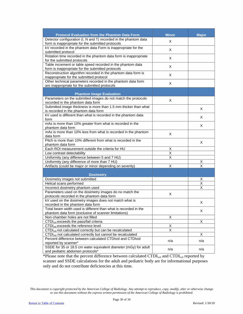
E. Phantom Scoring The phantom is evaluated in 3 areas; protocol evaluation from the phantom data form, image quality evaluation and dosimetry. One or more major deficiencies and/or 7 or more minor deficiencies total will fail the phantom review. Each required protocol will be evaluated for major and minor deficiencies.
This document is copyright protected by the American College of Radiology. Any attempt to reproduce, copy, modify, alter or otherwise change or use this document without the express written permission of the American College of Radiology is prohibited.
Page 30 of 34 Return to Table of Contents Revised: 1/30/18
Protocol Evaluation from the Phantom Data Form Minor Major Detector configuration (I, N and T) recorded in the phantom data form is inappropriate for the submitted protocols X
kV recorded in the phantom data Form is inappropriate for the submitted protocol X
Rotation time recorded in the phantom data form is inappropriate for the submitted protocols X
Table increment or table speed recorded in the phantom data form is inappropriate for the submitted protocols X
Reconstruction algorithm recorded in the phantom data form is inappropriate for the submitted protocol X
Other technical parameters recorded in the phantom data form are inappropriate for the submitted protocols X
Phantom Image Evaluation
Parameters on the submitted images do not match the protocols recorded in the phantom data form X
Submitted image thickness is more than 1.5 mm thicker than what is recorded in the phantom data form X
kV used is different than what is recorded in the phantom data form X
mAs is more than 10% greater from what is recorded in the phantom data form X
mAs is more than 10% less from what is recorded in the phantom data form X
Pitch is more than 10% different from what is recorded in the phantom data form X
Each ROI measurement outside the criteria for HU X Low contrast detectability X Uniformity (any difference between 5 and 7 HU) X Uniformity (any difference of more than 7 HU) X Artifacts (could be major or minor depending on severity) X X
Dosimetry Dosimetry images not submitted X Helical scans performed X Incorrect dosimetry phantom used X Parameters used on the dosimetry images do no match the protocols recorded in the phantom data form X
kV used on the dosimetry images does not match what is recorded in the phantom data form X
Total beam width used is different than what is recorded in the phantom data form (exclusive of scanner limitations) X
Non-chamber holes are not filled X CTDIvol exceeds the pass/fail criteria X CTDIvol exceeds the reference level X CTDIvol not calculated correctly but can be recalculated X CTDIvol not calculated correctly but cannot be recalculated X Percent difference between calculated CTDIvol and CTDIvol reported by scanner* n/a n/a
SSDE for 35 or 18.5 cm water equivalent diameter (mGy) for adult and pediatric abdomen protocols* n/a n/a
*Please note that the percent difference between calculated CTDIvol and CTDIvol reported by scanner and SSDE calculations for the adult and pediatric body are for informational purposes only and do not contribute deficiencies at this time.

This document is copyright protected by the American College of Radiology. Any attempt to reproduce, copy, modify, alter or otherwise change or use this document without the express written permission of the American College of Radiology is prohibited.
Page 31 of 34 Return to Table of Contents Revised: 1/30/18
F. Prepare Phantom Images for Submission After scanning the Gammex 464 and all required CTDI phantoms according to the CT Phantom Testing Instructions, prepare your images for submission.
1. Name each series separately according to the protocol used and the phantom scanned. (e.g. Adult head ACR phantom, Adult head CTDI phantom etc.)
2. Electronic submission of images
• If you selected electronic image submission in your online application, please follow the ACR Accreditation Electronic Submission Instructions at: http://www.acraccreditation.org/~/media/ACRAccreditation/Documents/General/ElectronicSubmissionofImages.pdf?la=en.
3. CD submission of images
• All phantom images must be in a DICOM format.
• Burn a total of 2 discs for each unit listed on the accreditation application. Separate units must be burned onto separate discs. Each disc must contain all required Gammex phantom images and dosimetry images.
• The discs may be DICOM images only or may have an embedded viewer.
• Open and check each disc to ensure all required images are present.

This document is copyright protected by the American College of Radiology. Any attempt to reproduce, copy, modify, alter or otherwise change or use this document without the express written permission of the American College of Radiology is prohibited.
Page 32 of 34 Return to Table of Contents Revised: 1/30/18
VII. Submitting and Labeling All Material 1. Log into the ACRedit database and fill out all required clinical and phantom data forms and
submit the online testing packet.
2. If submitting the clinical and phantom image by electronic upload, read and follow the User Instructions for Electronic Submission of Images at http://www.acraccreditation.org/~/media/ACRAccreditation/Documents/General/ElectronicSubmissionofImages.pdf?la=en
3. If submitting materials by CD, select “print forms for submission”.
4. Label the discs and forms by placing the appropriate barcode label on each data form.
5. Place the appropriate CD labels on the disc envelope. DO NOT PUT LABELS ON THE DISC.
6. Use a permanent marker to label the discs with the CTAP #.
Important: The correct labeling of your images, forms and discs is critical to properly identify the materials submitted for accreditation. Incorrect or incomplete labeling will delay the accreditation process. The ACR will return your package if the images are not labeled properly. Failure to submit the online testing package or the printed forms for submission directly from the ACRedit database could result in the expiration of your testing cycle, with the requirement of reinstatement at full fee in order for your facility to continue the process of seeking accreditation.

This document is copyright protected by the American College of Radiology. Any attempt to reproduce, copy, modify, alter or otherwise change or use this document without the express written permission of the American College of Radiology is prohibited.
Page 33 of 34 Return to Table of Contents Revised: 1/30/18
VIII. Mailing Instructions If submitting by mail, please send all phantom CDs and forms, clinical CDs and forms and your annual system performance evaluation to:
CT Accreditation Program American College of Radiology
1891 Preston White Dr. Reston, Virginia 20191-4397
Please note that your accreditation submission contains HIPAA data, so we strongly
recommend that you send your submission via a traceable method with a signature required for delivery.
All images submitted for review on film or CD will be returned once the accreditation evaluation is complete.

This document is copyright protected by the American College of Radiology. Any attempt to reproduce, copy, modify, alter or otherwise change or use this document without the express written permission of the American College of Radiology is prohibited.
Page 34 of 34 Return to Table of Contents Revised: 1/30/18
IX. CT Accreditation Checklist Be sure to keep copies of the completed application, submitted images and any additional submitted information for your records.
Please ensure that all items below are complete before returning the submission to the ACR for accreditation review. The review process will not begin until your submission is complete. All items must be submitted for each unit being accredited.
A. Electronic Submissions If submitting electronically, ensure all appropriate items have been uploaded and the
online testing packet is in a submitted status.
B. CD Submissions Two copies of clinical images on CD-ROM’S with appropriate labels.
Clinical Data Forms (one for each examination, printed from online testing package and appropriately labeled).
Clinical Scanning Protocols (one for each examination).
Two copies of phantom images, including the required dose images, on CD-ROM in DICOM format, uncompressed. Phantom images must be on separate CD from clinical images.
Phantom Data Form and Phantom Dose Form (printed from online testing package and appropriately labeled).
Annual System Performance Evaluation summary form signed by a medical physicist to include evaluation of technologist QC (appropriately labeled). Your medical physicist must use the summary form provided by the ACR or one similar that itemizes the pass-fail results of all of the same tests using the same names and order as is outlined on the ACR form.
Corrective Action Documentation for any problems found on the Annual System Performance Evaluation.
Place all of your testing materials in a box and ship to ACR headquarters at the address indicated on the labels in your packet. Please take care in packaging your materials. Damaged testing materials will be returned to your site for replacement. Please note that your accreditation submission contains HIPAA data, so we strongly recommend that you send your submission via a traceable method with a signature required for delivery.