ACP+: DIY Preamp and Headphone Amplifier ProjectACP+: DIY Preamp and Headphone Amplifier Project At...
12
ACP+: DIY Preamp and Headphone Amplifier Project At the first Burning Amp Festival in 2007, a young attendee, Nelson Brock and his parents Dana and Liz, displayed a nice pair of loudspeakers using the Pioneer Bofu full range drivers in Voigt enclosures. They were so well received that subsequently the Brock family hosted a DIY audio event called “Speaker Camp”, where a group of enthusiasts showed up on a weekend day and assembled a bunch of them to take home. The success of this inspired the later effort called “Amp Camp”, and I had the opportunity to design the amplifier, referred to as the Amp Camp Amp (ACA), a small single-ended Class A amplifier powered by a desktop switching supply and delivering about 5 watts. This effort was also a success, and years later the ACA kit is still popular at the diyAudio website and has also enjoyed a small upgrade in power and performance. So here we are in 2019, and the people organizing the Burning Amp Festival had the idea of joining an “audio camp” type of event to BAF, and asked me to design a preamp that would also serve to drive headphones. The result is this circuit: The gain stage for each channel resembles a miniature version of the First Watt J2 amplifier, with an input circuit using a differential pair of P channel Jfets Q1 and Q2 biased by a constant current source Jfet Q3, and driving a Common Source Mosfet Q6 which in turn is biased by Mu-Follower Q5. Q5 is controlled by opto-isolator Q4, which sets a DC voltage based on the sum of the currents through Q5 and Q6, keeping that sum constant.
Transcript of ACP+: DIY Preamp and Headphone Amplifier ProjectACP+: DIY Preamp and Headphone Amplifier Project At...
ACP+: DIY Preamp and Headphone Amplifier Project
At the first Burning Amp Festival in 2007, a young attendee, Nelson Brock and his parents Dana and Liz, displayed a nice pair of loudspeakers using the Pioneer Bofu full range drivers in Voigt enclosures. They were so well received that subsequently the Brock family hosted a DIY audio event called “Speaker Camp”, where a group of enthusiasts showed up on a weekend day and assembled a bunch of them to take home.
The success of this inspired the later effort called “Amp Camp”, and I had the opportunity to design the amplifier, referred to as the Amp Camp Amp (ACA), a small single-ended Class A amplifier powered by a desktop switching supply and delivering about 5 watts. This effort wasalso a success, and years later the ACA kit is still popular at the diyAudio website and has also enjoyed a small upgrade in power and performance.
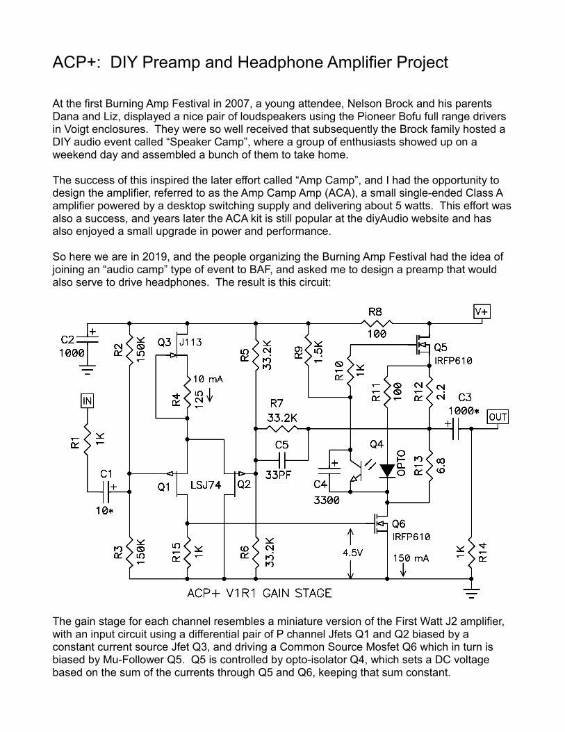
So here we are in 2019, and the people organizing the Burning Amp Festival had the idea of joining an “audio camp” type of event to BAF, and asked me to design a preamp that would also serve to drive headphones. The result is this circuit:
The gain stage for each channel resembles a miniature version of the First Watt J2 amplifier, with an input circuit using a differential pair of P channel Jfets Q1 and Q2 biased by a constant current source Jfet Q3, and driving a Common Source Mosfet Q6 which in turn is biased by Mu-Follower Q5. Q5 is controlled by opto-isolator Q4, which sets a DC voltage based on the sum of the currents through Q5 and Q6, keeping that sum constant.
Consistent with the topology based on the J2, I selected parts and values so as to somewhat replicate the sonic signature, including a distortion characteristic with the signature negative phase second harmonic character.
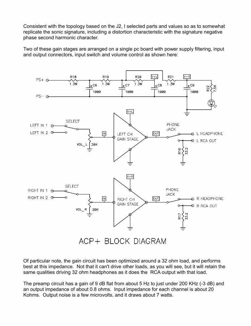
Two of these gain stages are arranged on a single pc board with power supply filtering, input and output connectors, input switch and volume control as shown here:
Of particular note, the gain circuit has been optimized around a 32 ohm load, and performs best at this impedance. Not that it can't drive other loads, as you will see, but it will retain the same qualities driving 32 ohm headphones as it does the RCA output with that load.
The preamp circuit has a gain of 9 dB flat from about 5 Hz to just under 200 KHz (-3 dB) and an output impedance of about 0.8 ohms. Input impedance for each channel is about 20 Kohms. Output noise is a few microvolts, and it draws about 7 watts.

Here is the response curve.
And the high frequency square wave:
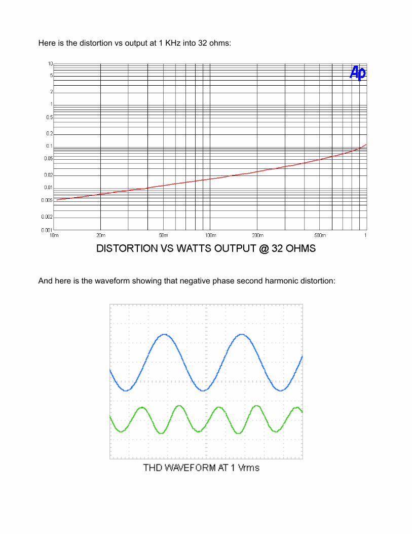
Here is the distortion vs output at 1 KHz into 32 ohms:
And here is the waveform showing that negative phase second harmonic distortion:

Distortion vs frequency:
Construction Notes
Jim Tiemann (aka 6L6) will be supervising assembly of the ACP+ at the Burning Amp Festival Saturday event, and is also preparing a build guide for the project which will be posted at the www.diyaudio.com web site.
Note that there are a couple changes between this and the earlier artwork which will be at BAF in terms of resistor values. R3 is now 150K, R4 is 125 ohms and R9 is now 1.5Kohm.
In the case of R4, the J113 Jfets I had in stock had a higher Vp, so the value is adjusted from 68 ohms up to 125 ohms to give the 10 mA current source value. R9 had to be increased to help delay down the activation of the output stage bias so that the wall-wart switching supply could have time to charge up the supply capacitors.
So you want to go by this drawing and the schematic for these resistors, not the value screened on the pc board. The correct values were added to the kits at BAF.

Bill of Materials
PART QTY DESCRIPTION
R1, 10, 14, 15 8 1KR2, 3 4 150KR4 2 125R5, 6, 7 6 33.2KR8, 11 4 100R9 2 1.5KR12 2 2.2R13 2 6.8R16,17 2 33.2R18, 19, 20, 21 4 1 3W
Q1, 2 4 LSJ74Q3 2 J113Q4 2 4N35Q5, 6 4 IRFP610
C1 2 10 UFC3 2 1000 UF GOLDC2, 6, 7, 8, 9 6 1000 UFC4 2 3300 UFC5 2 33 PF
RCA CONN 6 MOUSER - CUI RCJ-04XPHONE JACK 1 MOUSER - NEUTRIK NYS216GPOWER CONN 1 DIGIKEY CP-037B-NDSWITCH 1 MOUSER - 612-100-F2461VOLUME POT 1 ALPS 516G 20K X 2KNOB 1 MPJA.COMHEAT SINKS 4 DIGIKEY HS193-ND6-32 X 5/8 SCREWS 46-32 LOCK NUTS 4M3 X10MM SCREWS 4M3 LOCKNUTS 4NYLON SPACERS 4 6-32 X 1/4” X 1/4”PCB CIRCUIT 1PCB BASE 1POWER SUPPLY 1 TRIAD WSU240-0500
RESISTORS .5 WATT 1% EXCEPT R18, 19, 20, 20 at 3 WATTDUPLICATE PART NUMBERS ON TWO GAIN STAGESALL ELECTROLYTIC ARE 25V, C3 IS “AUDIO GRADE” NICHICONQ1, Q2 JFETS ARE MATCHED WITHIN 1 MA IDss
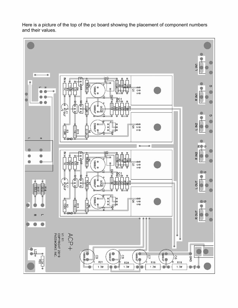
Here is a picture of the top of the pc board showing the placement of component numbers and their values.

I like to stuff things by height - resistors have the lowest profile, so they go in first. I recommend that you use a multi-meter to check each one before you stuff it in - the colors can be hard to read, and this is the most common mistake. Other common mistakes are about polarity of caps - there is a + marked on the boards, and the longer leads of electrolytics are + by convention. Check this before soldering, and you can refer to the photo below (slightly earlier version - we're currently up to 4th version)
Notice also the orientation of the transistors, and remember the dot on the opto-isolator.
Of the transistors involved, only the TO-220 output devices are particularly static sensitive. I would do those last, and you want to handle those carefully until they are soldered in. Bending the leads on those to get them to fit with the sink/board holes has to be done carefully as the alignment is rather tight. Speaking of which, the screws for the sinks need to be firm but not too tight.....
The input and output RCA connectors are designed to snap into the pc board and have the two leads soldered. I suggest a 45 watt or so iron for this, as you want to get the job done fairly quickly and not melt the plastic, otherwise smaller irons are preferred.
The power supply provided at BAF is left over from a previous project where a batch of Triad switchers were purchased that turned out to have the wrong polarity for the connectors on theboard. Here we are using them hardwired to the power input. Note that the wire with the grey
strip is the negative and the other wire is positive. I suggest testing this with a multi-meter before attaching it to the board. In addition to the holes for a barrel connector, power can bewired to smaller holes next to the connector, labeled V+ and Gnd.
The kit comes with a base plate made up of a circuit board with a ground shield, making for operation without a chassis. It is mounted as a parallel surface below the main board with the6-32 screws, nuts and spacers provided.
Testing the assembled ACP+ consists of plugging it into the wall. The power supply will makeseveral pulsed efforts to charge the capacitors, and you will see this with the LED. After two or three tries, it will fire up and the LED will glow.
At this point, you should be able to confirm +24 volts with your muli-meter, and then you will want to measure the DC voltage drop across R18. The preamp draws about 0.3 amps, and so you expect to see about 0.3V across this 1 ohm resistor.
After that, you check the point on each channel labeled DC1 (near R12 and R13) and confirm about 11 volts DC. Exact value is not critical, plus or minus a volt....
If you have these voltages, you should be good to go. Operation is pretty straightforward, justremember that plugging in headphones disables the RCA outputs.
Conclusion
Well, with a little luck there you are. When I first got this circuit up and running, my biggest concern was that it would be quiet enough, and plugging in my Sony headphones it apparently was. After that, there was little to worry about, but I was curious to see how well this might drive a pair of efficient speakers. While output impedance is about 0.8 ohms, there is rather limited voltage and current available.
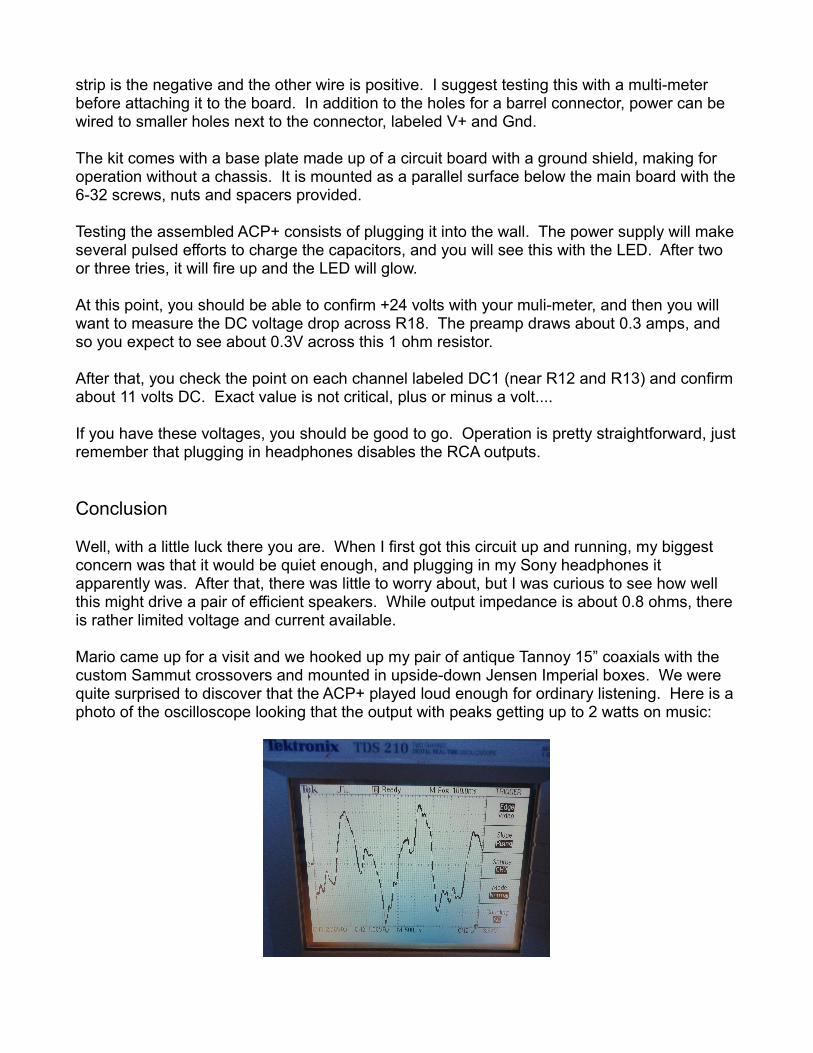
Mario came up for a visit and we hooked up my pair of antique Tannoy 15” coaxials with the custom Sammut crossovers and mounted in upside-down Jensen Imperial boxes. We were quite surprised to discover that the ACP+ played loud enough for ordinary listening. Here is aphoto of the oscilloscope looking that the output with peaks getting up to 2 watts on music:
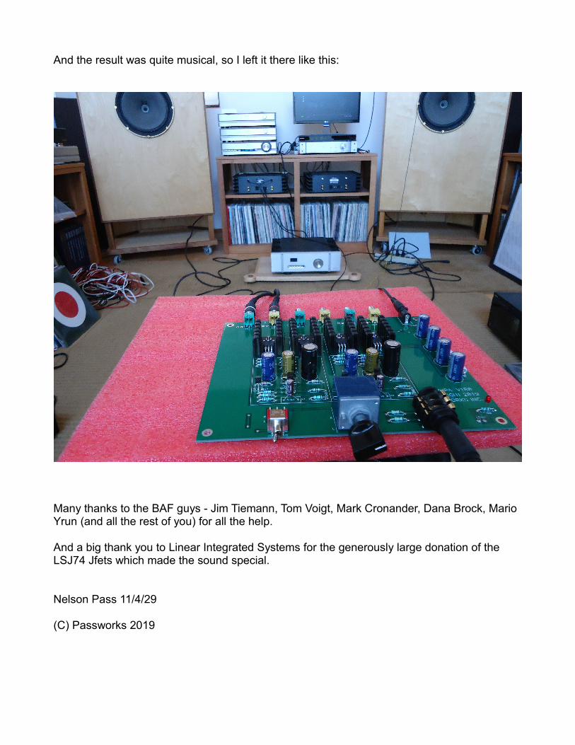
And the result was quite musical, so I left it there like this:
Many thanks to the BAF guys - Jim Tiemann, Tom Voigt, Mark Cronander, Dana Brock, Mario Yrun (and all the rest of you) for all the help.
And a big thank you to Linear Integrated Systems for the generously large donation of the LSJ74 Jfets which made the sound special.
Nelson Pass 11/4/29
(C) Passworks 2019


![HEADPHONE PREAMP Price: £599 Musical Fidelity MX-HPA · Auralic Taurus MkII [HFN Jan ’15]. But characteristically, Musical Fidelity has spotted the trend and fearlessly acted upon](https://static.fdocuments.net/doc/165x107/5f60340c62ef4e643f0fdb7b/headphone-preamp-price-599-musical-fidelity-mx-hpa-auralic-taurus-mkii-hfn-jan.jpg)
![DAC/HEADPHONE PREAMP Chord DAVE€¦ · Hugo [HFN Dec ’15], with its overtones of a Cotswold weekender, now we have the DAVE – and you don’t get many Daves in the Cotswolds.](https://static.fdocuments.net/doc/165x107/5f60345539c3d74cf8113217/dacheadphone-preamp-chord-dave-hugo-hfn-dec-a15-with-its-overtones-of-a-cotswold.jpg)