InTech-Periodically Poled Acoustic Wave Guide and Transducers for Radio Frequency Applications(1)
Upload
chathuranga-basnayakaCategory
view
200download
2
Acoustic Transducers
• Transducers are devices that convert energy of one form to another.
• In acoustics we are mainly concerned with conversion of
acoustic energy to electrical energy or electrical energy to acoustic energy
Acoustic waves
• Acoustic waves are pressure waves. • They are different from Electromagnetic (EM)
waves in that they need a medium to propagate.• The waves propagate by induced vibrations in the
medium. • Therefore acoustic waves do not propagate in a
vacuum unlike EM waves.
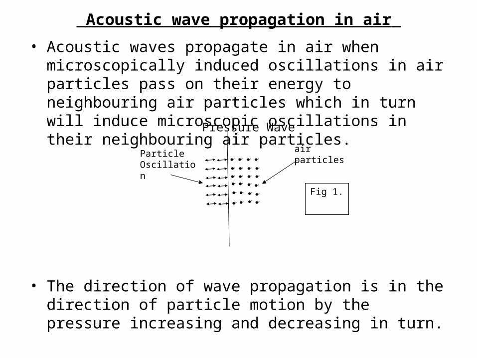
Acoustic wave propagation in air • Acoustic waves propagate in air when
microscopically induced oscillations in air particles pass on their energy to neighbouring air particles which in turn will induce microscopic oscillations in their neighbouring air particles.
• The direction of wave propagation is in the direction of particle motion by the pressure increasing and decreasing in turn.
ParticleOscillation
air particles
Fig 1.
Pressure Wave
• This type of pressure wave is called a compressional wave where the direction of wave propagation is normal to the pressure surface.
• There is weak bonding between adjacent air particles so no wave is coupled in the plane of the pressure wave (which takes place when the bonding between particles are strong as in a solid).
• The speed of sound in air is 343 m/s
• Audible Frequency Range 20 Hz to 20 kHz
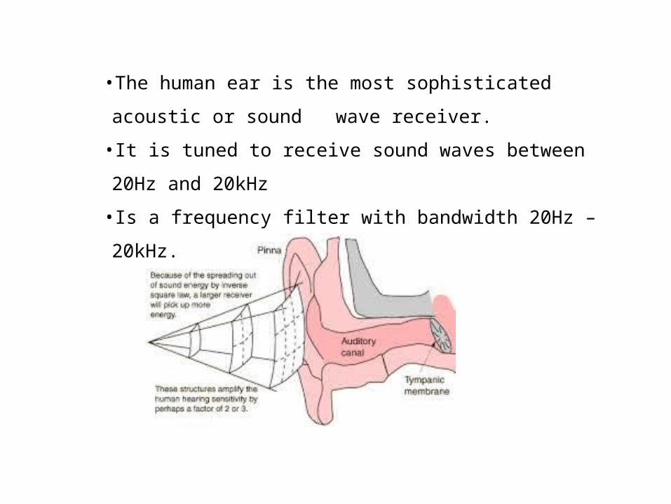
•The human ear is the most sophisticated acoustic or sound wave receiver.
•It is tuned to receive sound waves between 20Hz and 20kHz
•Is a frequency filter with bandwidth 20Hz – 20kHz.
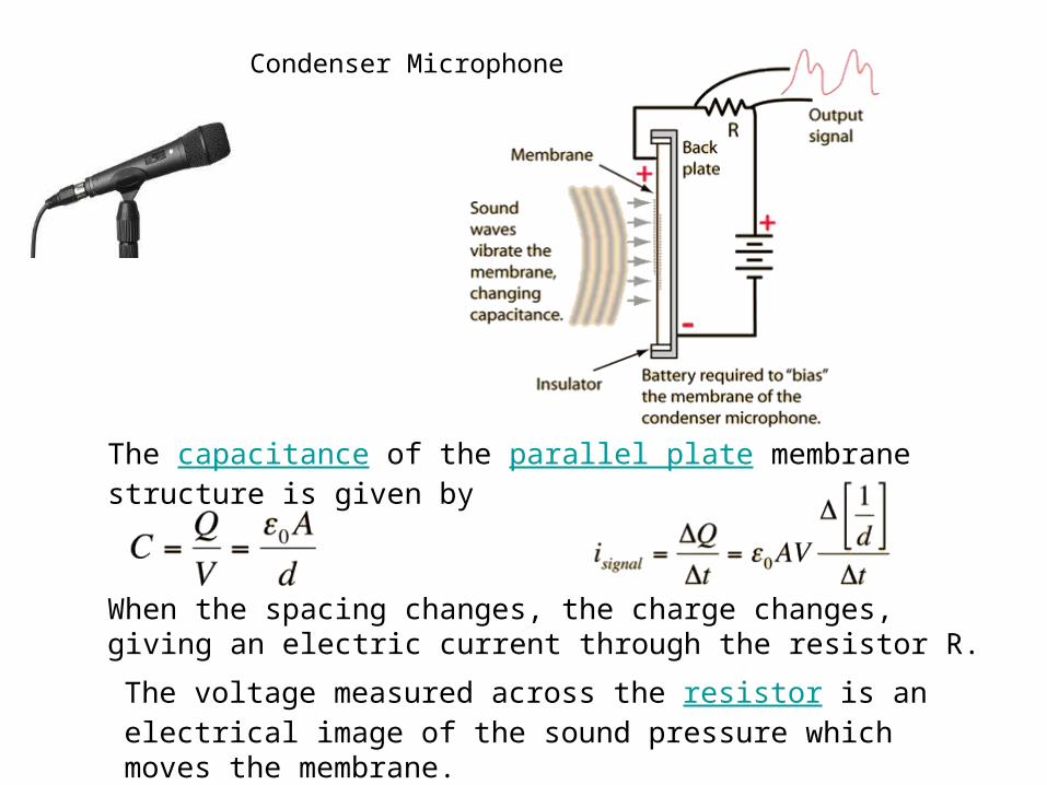
Condenser Microphone
The capacitance of the parallel plate membrane structure is given by
When the spacing changes, the charge changes, giving an electric current through the resistor R. The voltage measured across the resistor is an electrical image of the sound pressure which moves the membrane.
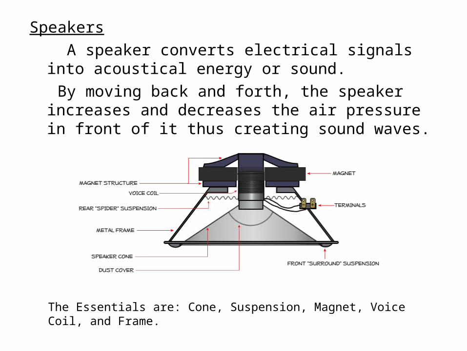
Speakers A speaker converts electrical signals into
acoustical energy or sound. By moving back and forth, the speaker increases
and decreases the air pressure in front of it thus creating sound waves.
The Essentials are: Cone, Suspension, Magnet, Voice Coil, and Frame.
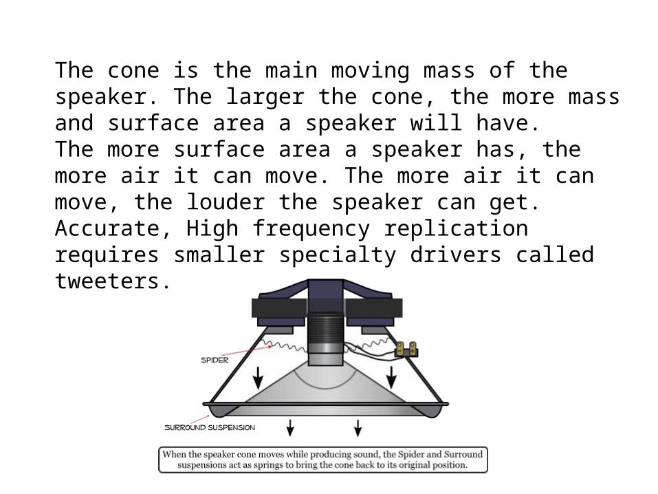
The cone is the main moving mass of the speaker. The larger the cone, the more mass and surface area a speaker will have. The more surface area a speaker has, the more air it can move. The more air it can move, the louder the speaker can get. Accurate, High frequency replication requires smaller specialty drivers called tweeters.
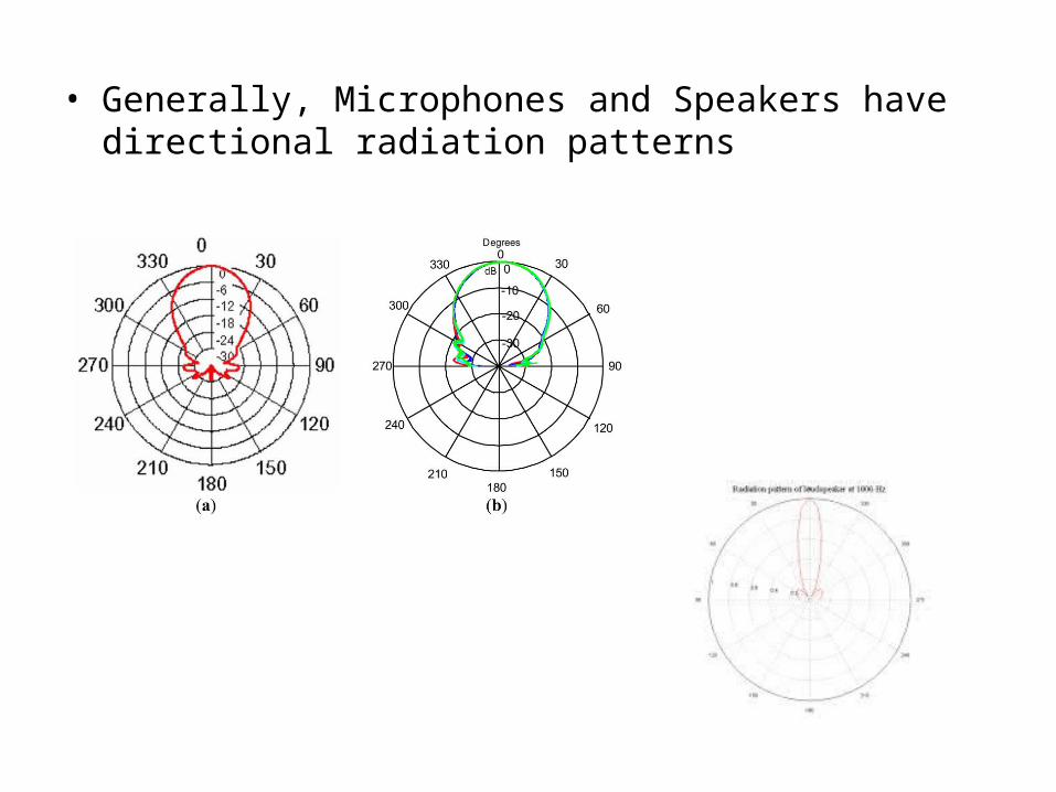
• Generally, Microphones and Speakers have directional radiation patterns
Acoustic waves in Water/Liquid • Applications: Sonar and Hydrophones (2kHz to
500kHz), Medical Ultrasonic Scanners (1 to 2MHz). • There is weak bonding between water molecules
therefore sound propagation is similar to that in air ie: only compressional waves propagate.
• Sound speed in water is 1482 m/s (normally taken as 1500 m/s) and dependent on the temperature of the water and salinity.
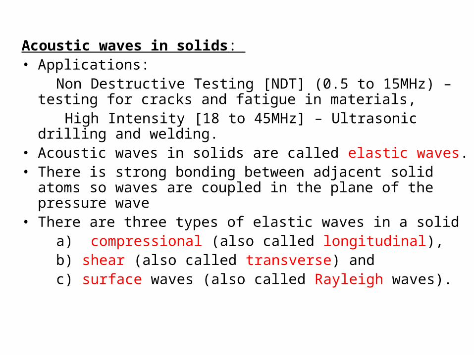
Acoustic waves in solids: • Applications: Non Destructive Testing [NDT] (0.5 to 15MHz) –
testing for cracks and fatigue in materials, High Intensity [18 to 45MHz] – Ultrasonic drilling and
welding. • Acoustic waves in solids are called elastic waves.• There is strong bonding between adjacent solid
atoms so waves are coupled in the plane of the pressure wave
• There are three types of elastic waves in a solid a) compressional (also called longitudinal), b) shear (also called transverse) and c) surface waves (also called Rayleigh waves).
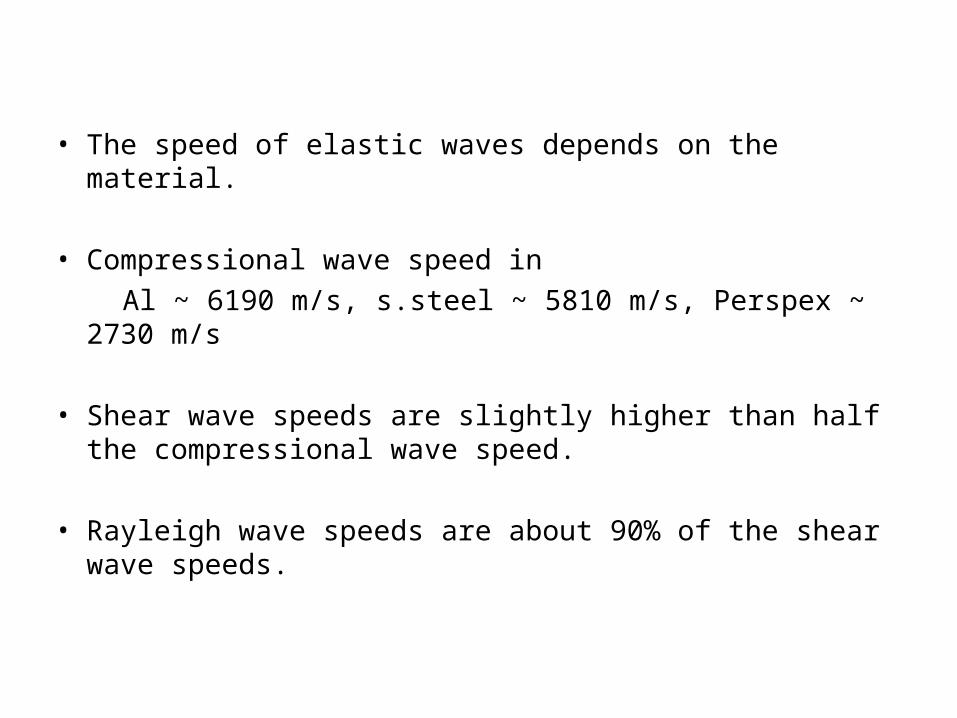
• The speed of elastic waves depends on the material.
• Compressional wave speed in Al ~ 6190 m/s, s.steel ~ 5810 m/s, Perspex ~ 2730
m/s
• Shear wave speeds are slightly higher than half the compressional wave speed.
• Rayleigh wave speeds are about 90% of the shear
wave speeds.

Elasticity: Stress and Strain
• When a material is stressed there is an associated deformation or elongation of the material.
z
y
x
z
y
T3
T3x
y
T3
T3 x
z
T4
T4
Extensional stressIn z direction
Compressional stressIn z direction
Shear stressAbout x direction
Elasticity: Stress and Strain
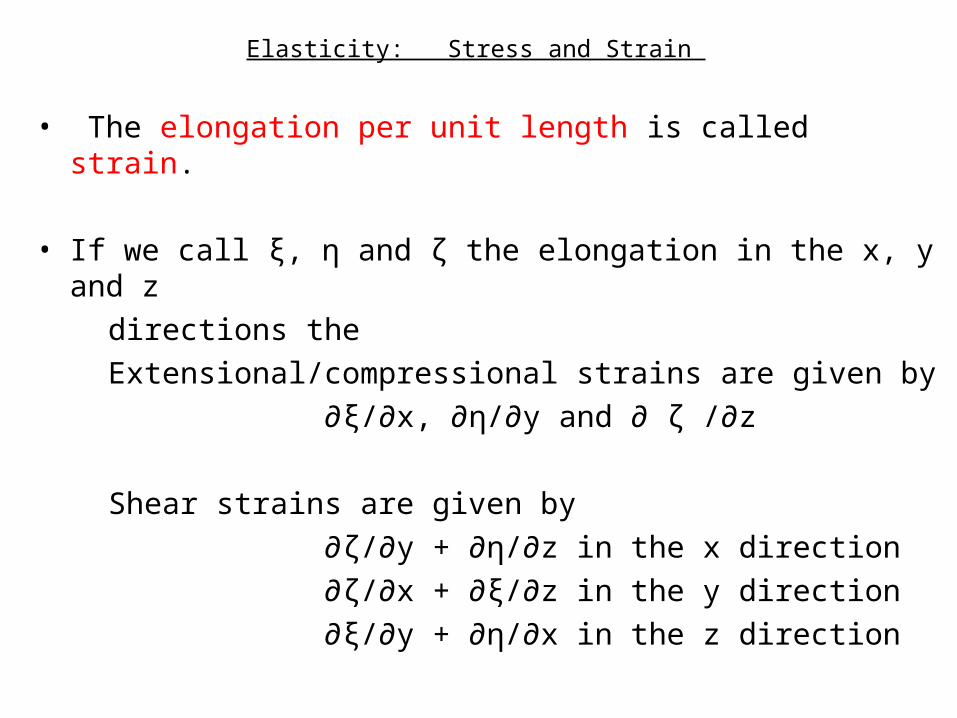
• The elongation per unit length is called strain.
• If we call ξ, η and ζ the elongation in the x, y and z directions the Extensional/compressional strains are given by ∂ξ/∂x, ∂η/∂y and ∂ ζ /∂z
Shear strains are given by ∂ζ/∂y + ∂η/∂z in the x direction ∂ζ/∂x + ∂ξ/∂z in the y direction ∂ξ/∂y + ∂η/∂x in the z direction
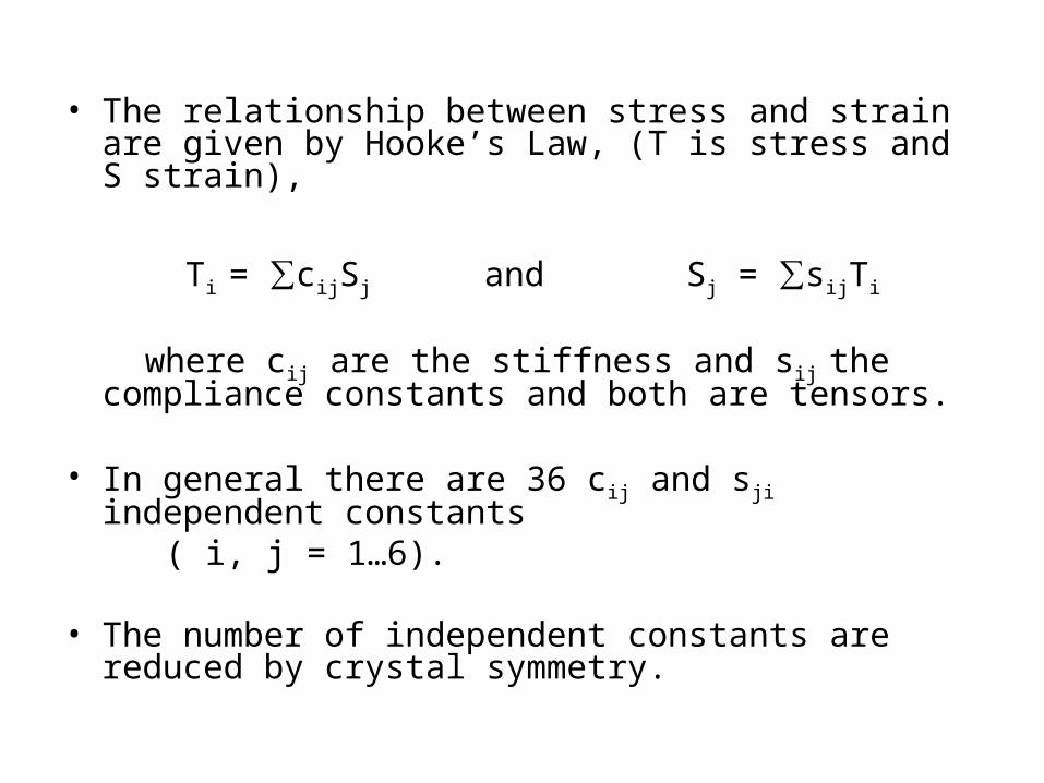
• The relationship between stress and strain are given by Hooke’s Law, (T is stress and S strain),
Ti = ∑cijSj and Sj = ∑sijTi
where cij are the stiffness and sij the compliance constants and both are tensors.
• In general there are 36 cij and sji independent constants
( i, j = 1…6).
• The number of independent constants are reduced by crystal symmetry.

Piezoelectricity
• Most acoustic transducers for underwater and NDT applications are based on excitation of materials that possess a property called Piezoelectricity.
• The active element in the transducer is piezoelectric.
• Piezoelectricity: Certain crystalline materials a) generate electric charge under mechanical stress (this is called the direct effect) and b) experience mechanical strain or deformation in the presence of an electric field (this is called the reverse or converse effect).
• Natural materials such as Quartz, and Tourmaline exhibit piezoelectricity.
• Ceramics such as BaTiO3, PbZrTiO3, PbNb2O6 exhibit piezoelectricity.
• These possess the ABO3 Pervoskite crystalline structure
• For any material to exhibit piezoelectricity the microscopic structure must not have a center of symmetry.
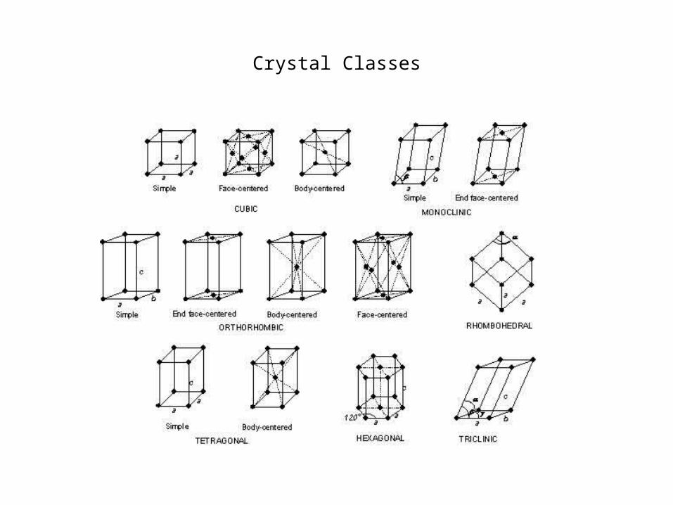
Crystal Classes

• Common materials found in piezoelectric transducers are :
PbZrTiO3 –Lead Zirconate Titanate or PZT and PbNb2O6 – Lead Metaniobate or PMN. • In transducers these ceramics (PZT, PMN) are
made into discs, cylinders and other useful shapes.• Discs and cylinders are the most common. • Electrodes are applied to opposite faces of the
discs or cylinders as shown in the figure.
Ceramic
Ceramic
Disc Cylinder
Electrodes

• The crystalline material in its normal form is not piezoelectric because of the random orientation of the electric polarization vectors of the domains.
• But when the material is heated above its Curie temperature (which depends on the material) and a strong DC electric field applied, the random distribution of the polarization vectors can be aligned in the direction of the applied DC field, as shown in the figure below.
• The process of applying the strong DC field at above Curie temperature and aligning the polarization vectors is called poling.
• After the alignment of the polarization (and cooling and removing the DC field) the material is piezoelectric.
Heat above CurieTemp +
DCfield
-
+
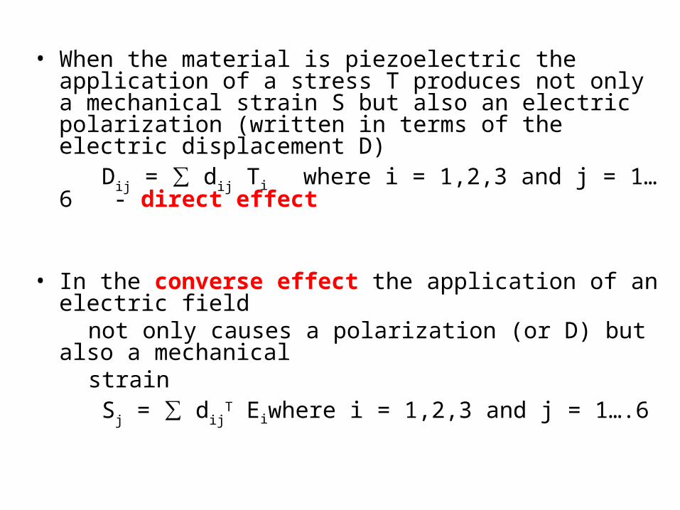
• When the material is piezoelectric the application of a stress T produces not only a mechanical strain S but also an electric polarization (written in terms of the electric displacement D)
Dij = ∑ dij Ti where i = 1,2,3 and j = 1…6 - direct effect
• In the converse effect the application of an electric
field not only causes a polarization (or D) but also a
mechanical strain Sj = ∑ dij
T Eiwhere i = 1,2,3 and j = 1….6
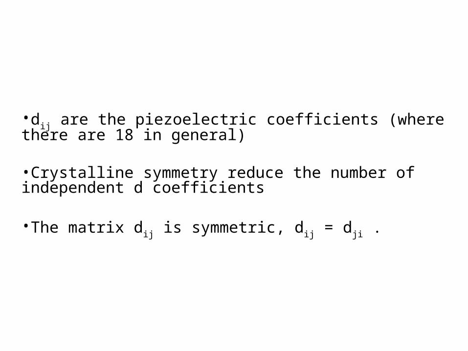
•dij are the piezoelectric coefficients (where there are 18 in general) •Crystalline symmetry reduce the number of independent d coefficients •The matrix dij is symmetric, dij = dji .
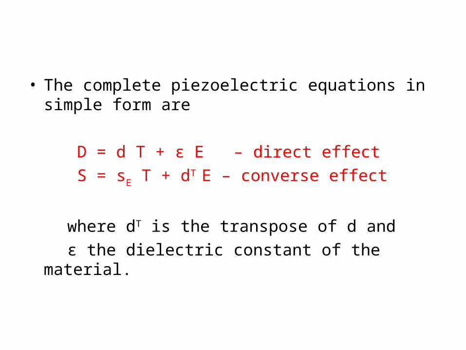
• The complete piezoelectric equations in simple form are
D = d T + ε E – direct effect S = sE T + dT E – converse effect where dT is the transpose of d and ε the dielectric constant of the material.
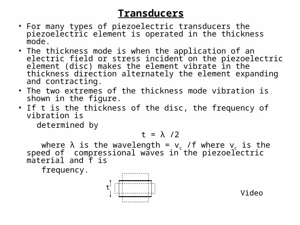
Transducers• For many types of piezoelectric transducers the
piezoelectric element is operated in the thickness mode.• The thickness mode is when the application of an electric
field or stress incident on the piezoelectric element (disc) makes the element vibrate in the thickness direction alternately the element expanding and contracting.
• The two extremes of the thickness mode vibration is shown in the figure.
• If t is the thickness of the disc, the frequency of vibration is
determined by t = λ /2 where λ is the wavelength = vc /f where vc is the speed of
compressional waves in the piezoelectric material and f is frequency.
tVideo

Discs
Rings
Cylinders
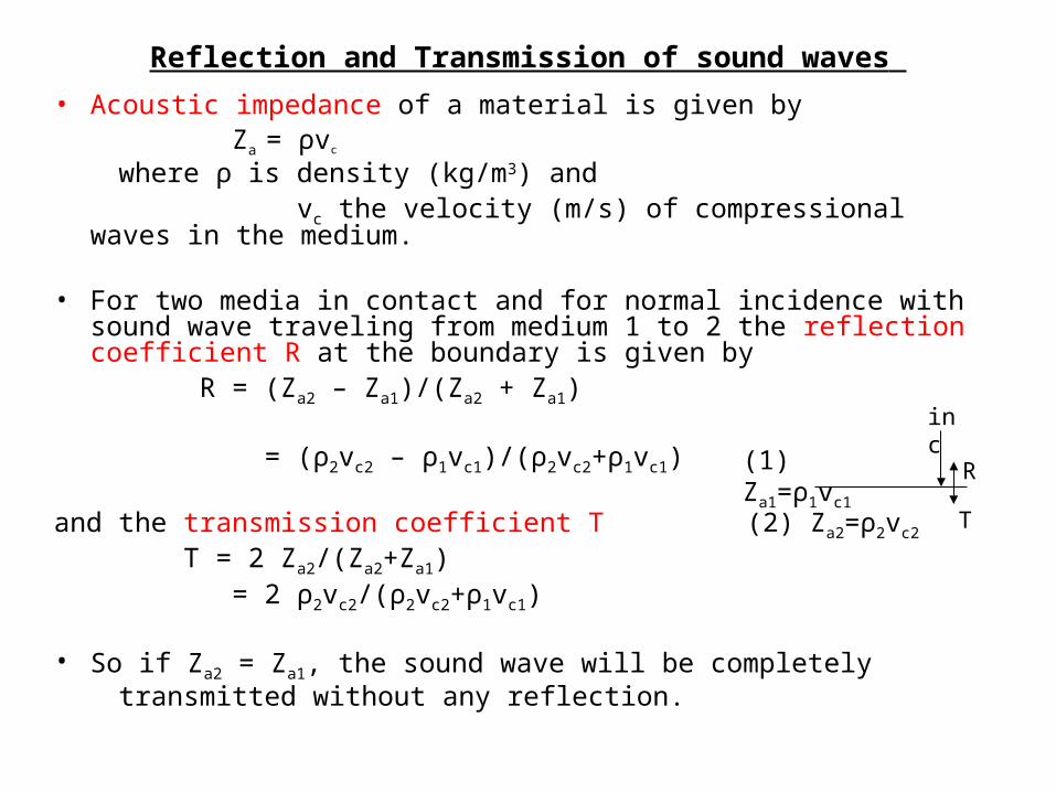
Reflection and Transmission of sound waves • Acoustic impedance of a material is given by Za = ρvc where ρ is density (kg/m3) and vc the velocity (m/s) of compressional waves in the
medium.
• For two media in contact and for normal incidence with sound wave traveling from medium 1 to 2 the reflection coefficient R at the boundary is given by
R = (Za2 – Za1)/(Za2 + Za1)
= (ρ2vc2 – ρ1vc1)/(ρ2vc2+ρ1vc1) and the transmission coefficient T T = 2 Za2/(Za2+Za1) = 2 ρ2vc2/(ρ2vc2+ρ1vc1)
• So if Za2 = Za1, the sound wave will be completely transmitted without any reflection.
inc
R
T
(1) Za1=ρ1vc1
(2) Za2=ρ2vc2
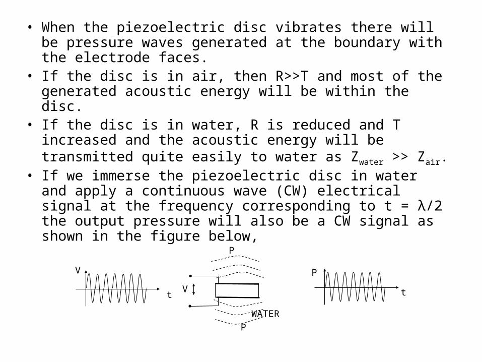
• When the piezoelectric disc vibrates there will be pressure waves generated at the boundary with the electrode faces.
• If the disc is in air, then R>>T and most of the generated acoustic energy will be within the disc.
• If the disc is in water, R is reduced and T increased and the acoustic energy will be transmitted quite easily to water as Zwater >> Zair.
• If we immerse the piezoelectric disc in water and apply a continuous wave (CW) electrical signal at the frequency corresponding to t = λ/2 the output pressure will also be a CW signal as shown in the figure below,
P
V
V
t
P
t
WATERP
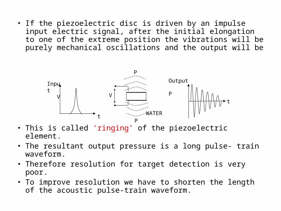
• If the piezoelectric disc is driven by an impulse input electric signal, after the initial elongation to one of the extreme position the vibrations will be purely mechanical oscillations and the output will be
• This is called ‘ringing’ of the piezoelectric element. • The resultant output pressure is a long pulse- train
waveform. • Therefore resolution for target detection is very poor. • To improve resolution we have to shorten the length
of the acoustic pulse-train waveform.
Input V
Output P
t
t
P
V
PWATER
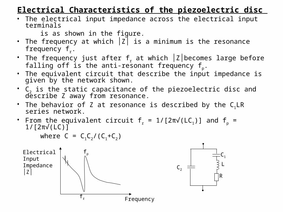
Electrical Characteristics of the piezoelectric disc • The electrical input impedance across the electrical input terminals is as shown in the figure. • The frequency at which │Z│ is a minimum is the resonance
frequency fr. • The frequency just after fr at which │Z│becomes large before falling
off is the anti-resonant frequency fp. • The equivalent circuit that describe the input impedance is given
by the network shown. • C2 is the static capacitance of the piezoelectric disc and describe Z
away from resonance. • The behavior of Z at resonance is described by the C1LR series
network. • From the equivalent circuit fr = 1/[2π√(LC1)] and fp = 1/[2π√(LC)] where C = C1C2/(C1+C2)
Frequency
ElectricalInput Impedance│Z│
fr
fp
C2L
R
C1
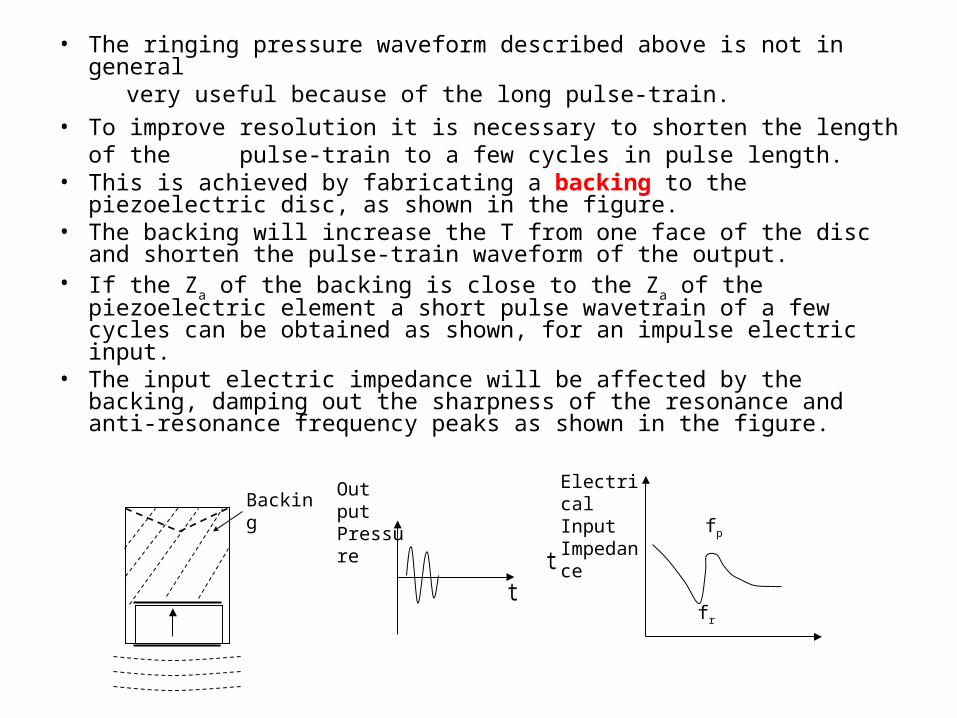
• The ringing pressure waveform described above is not in general
very useful because of the long pulse-train. • To improve resolution it is necessary to shorten the length of
the pulse-train to a few cycles in pulse length. • This is achieved by fabricating a backing to the piezoelectric
disc, as shown in the figure. • The backing will increase the T from one face of the disc and
shorten the pulse-train waveform of the output. • If the Za of the backing is close to the Za of the piezoelectric
element a short pulse wavetrain of a few cycles can be obtained as shown, for an impulse electric input.
• The input electric impedance will be affected by the backing, damping out the sharpness of the resonance and anti-resonance frequency peaks as shown in the figure.
Backing Out put Pressure
t t
ElectricalInput Impedance
fr
fp
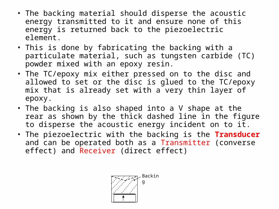
• The backing material should disperse the acoustic energy transmitted to it and ensure none of this energy is returned back to the piezoelectric element.
• This is done by fabricating the backing with a particulate material, such as tungsten carbide (TC) powder mixed with an epoxy resin.
• The TC/epoxy mix either pressed on to the disc and allowed to set or the disc is glued to the TC/epoxy mix that is already set with a very thin layer of epoxy.
• The backing is also shaped into a V shape at the rear as shown by the thick dashed line in the figure to disperse the acoustic energy incident on to it.
• The piezoelectric with the backing is the Transducer and can be operated both as a Transmitter (converse effect) and Receiver (direct effect)
Backing

• Since acoustic energy is transmitted to the backing the vibrations of the piezoelectric disc are damped and consequently the amplitude of the output pressure is reduced.
• Thus although we get an improvement in resolution by the shorter pulse length the sensitivity of the transducer will be affected due to loss in pressure amplitude.
• So a compromise has to be made between resolution and sensitivity.
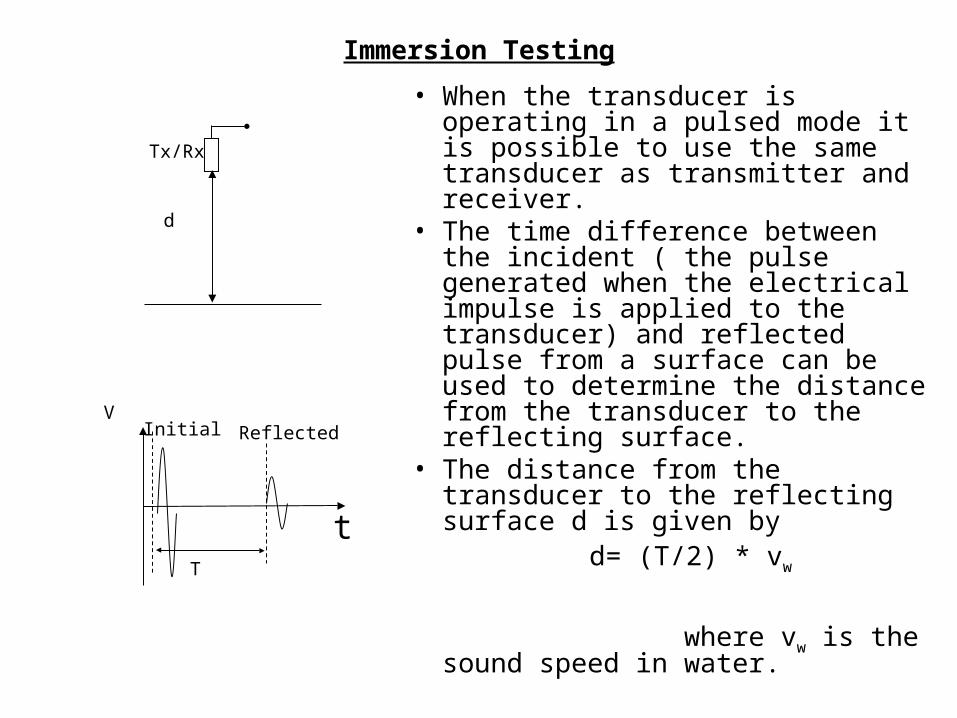
Immersion Testing• When the transducer is
operating in a pulsed mode it is possible to use the same transducer as transmitter and receiver.
• The time difference between the incident ( the pulse generated when the electrical impulse is applied to the transducer) and reflected pulse from a surface can be used to determine the distance from the transducer to the reflecting surface.
• The distance from the transducer to the reflecting surface d is given by
d= (T/2) * vw where vw is the sound speed in water.
d
Tx/Rx
t
VReflected
T
Initial
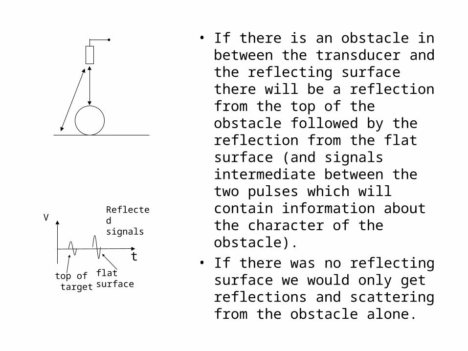
• If there is an obstacle in between the transducer and the reflecting surface there will be a reflection from the top of the obstacle followed by the reflection from the flat surface (and signals intermediate between the two pulses which will contain information about the character of the obstacle).
• If there was no reflecting surface we would only get reflections and scattering from the obstacle alone.
t
VReflected signals
top of target
flat surface
• These pulse trains can be analyzed by a variety of techniques in the time and frequency domains to
obtain information about the characteristics of the obstacle (target).
• This is the basic principle used in SONAR (2kHz to 500kHz), for target identification and also in medical applications to obtain echo-graphs in medical ultrasonic scanners (1 to 2MHz).
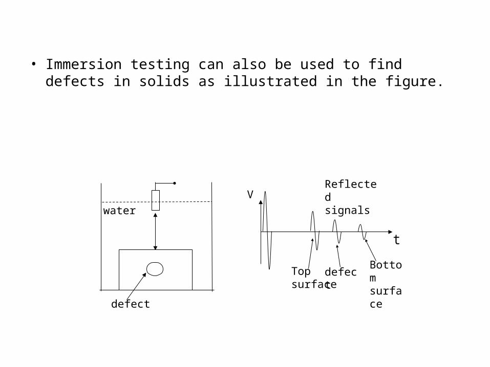
• Immersion testing can also be used to find defects in solids as illustrated in the figure.
t
VReflected signals
defect
water
Topsurface
defectBottom surface
Hydrophones
• Hydrophones are devices complimentary to microphones in air.
• These are also transducers but are generally used only in converting acoustic to electrical signals (SONAR receptors).
• These are generally used only as listening devices underwater and find numerous applications such as submarine, fish detection, sea floor mapping.
• To have a wide angle of reception from any directions hydrophones are normally made from cylindrical piezoelectric elements.
Some Applications
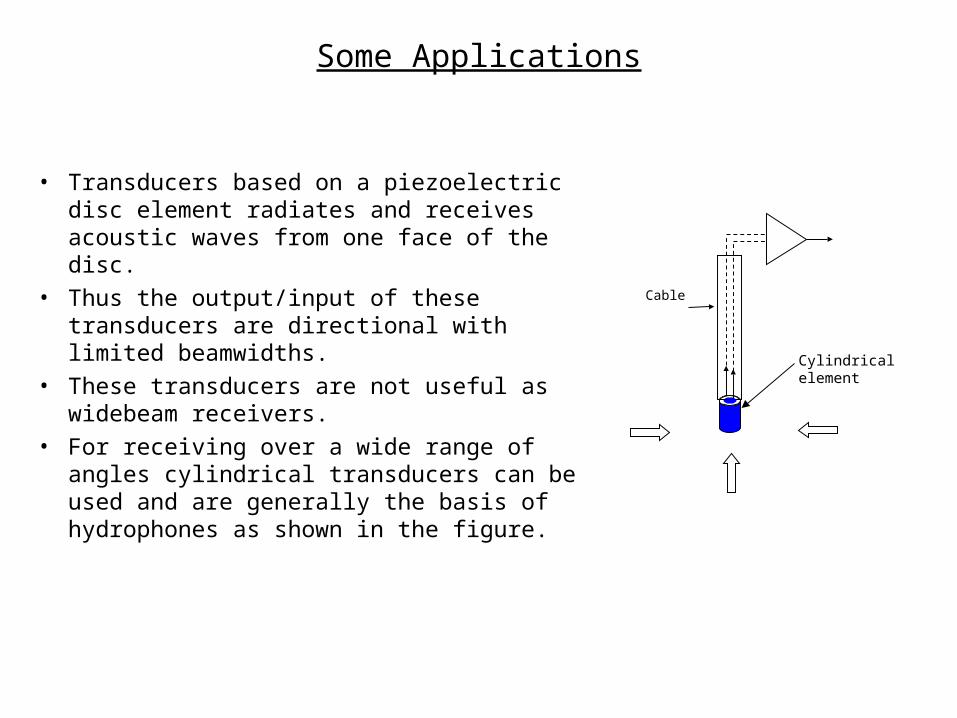
• Transducers based on a piezoelectric disc element radiates and receives acoustic waves from one face of the disc.
• Thus the output/input of these transducers are directional with limited beamwidths.
• These transducers are not useful as widebeam receivers.
• For receiving over a wide range of angles cylindrical transducers can be used and are generally the basis of hydrophones as shown in the figure.
Cable
Cylindrical element
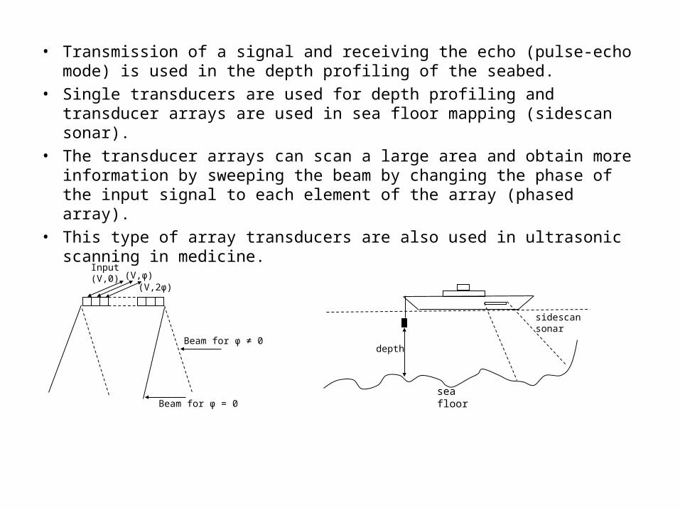
• Transmission of a signal and receiving the echo (pulse-echo mode) is used in the depth profiling of the seabed.
• Single transducers are used for depth profiling and transducer arrays are used in sea floor mapping (sidescan sonar).
• The transducer arrays can scan a large area and obtain more information by sweeping the beam by changing the phase of the input signal to each element of the array (phased array).
• This type of array transducers are also used in ultrasonic scanning in medicine.
Input (V,0) (V,φ)
(V,2φ)
Beam for φ = 0
Beam for φ ≠ 0depth
sidescan sonar
sea floor
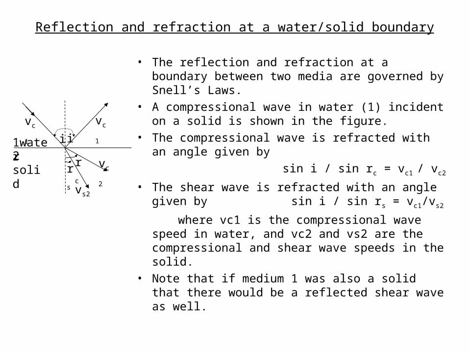
Reflection and refraction at a water/solid boundary
• The reflection and refraction at a boundary between two media are governed by Snell’s Laws.
• A compressional wave in water (1) incident on a solid is shown in the figure.
• The compressional wave is refracted with an angle given by
sin i / sin rc = vc1 / vc2 • The shear wave is refracted with an angle
given by sin i / sin rs = vc1/vs2
where vc1 is the compressional wave speed in water, and vc2 and vs2 are the compressional and shear wave speeds in the solid.
• Note that if medium 1 was also a solid that there would be a reflected shear wave as well.
ii1water2 solid
vc1 vc1
rcrsvc2
vs2

Application in ultrasonic inspection (NDT):
• In ultrasonic inspection the presence of two wave types with different velocities in the material under test will give confusing results.
• So the angle of incidence is adjusted to be greater than the critical angle i’ for compressional wave refraction , allowing only the refracted shear wave to be transmitted.
• Critical angle for compressional wave refraction is i’ = sin-1( vc1 / vc2) • This is accomplished by mounting the transducer on a shoe
as shown in the figure. • The resultant structure is called an angled probe.
shear
absorbing
medium
perspexi
i > i’
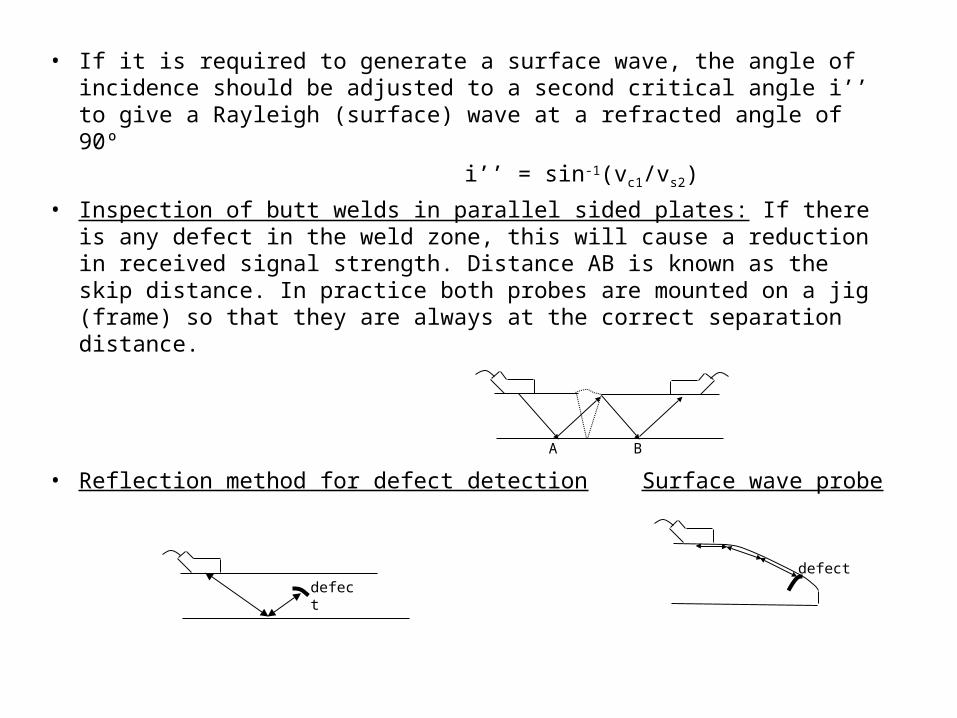
• If it is required to generate a surface wave, the angle of incidence should be adjusted to a second critical angle i’’ to give a Rayleigh (surface) wave at a refracted angle of 90º
i’’ = sin-1(vc1/vs2)• Inspection of butt welds in parallel sided plates: If there is any
defect in the weld zone, this will cause a reduction in received signal strength. Distance AB is known as the skip distance. In practice both probes are mounted on a jig (frame) so that they are always at the correct separation distance.
• Reflection method for defect detection Surface wave probeA B
defectdefect


![Interdigital Sensors and Transducers · of acoustic sensor technology have been written [15], [16] and somewhat reduce the need for the acoustic sensor tech-nology coverage in this](https://static.fdocuments.net/doc/165x107/605dd211c6383d25fb254655/interdigital-sensors-and-transducers-of-acoustic-sensor-technology-have-been-written.jpg)