Effect of Stray Currents on Underground Pipelines within ...
32nd EWGAE 15
Czech Society for Nondestructive Testing32nd European Conference on Acoustic Emission TestingPrague, Czech Republic, September 07-09, 2016
ACOUSTIC EMISSION TESTING OF UNDERGROUND PIPELINES OF CRUDE OIL OF FUEL STORAGE DEPOTS
Ireneusz BARAN 1, Igor LYASOTA 1, Krzysztof SKROK 2 1Cracow University of Technology, Laboratory of Applied Research; Krakow, Poland
Phone: +48 12 628 32 74, Fax: +48 12 628 37 45; e-mail: [email protected] 2PERN S.A., Plock, Poland
Abstract
Considerable quantity of underground in-plant pipelines of crude oil of fuel storage depots and refineries is operated for more than thirty years. Corrosion damages and material degradation are the main causes for structural failures of such underground pipelines. Such failures not detected on time and not monitored in time are potentially the reasons of major breakdowns of the infrastructure of technological underground pipeline installations in-service and finally are the risks of pollution of the environment. The preventive maintenance activities are usually carried out on time driven basis, but evolving defects have to be identified in time to enable appropriate repairs. The primary disadvantages are limited access to pipelines and limited possibilities of testing, due to the necessity for off-line pressure tests of a big part of underground pipeline installation, possible visual inspection and follow-up non-destructive tests (NDT). Based on these facts, we conducted investigations for application of AE testing method of underground pipelines during pressure tests using liquid product transported through pipe. We present the AE investigation on pipeline materials and on real underground pipelines.
Keywords: underground pipelines, AE testing, AE wave propagation in liquid and in pipeline
1. Introduction A significant part of underground pipelines for transport of petroleum products of the petrochemical industry has been operated for over thirty years. The manufacturing flaws of low carbon steel from the period of pipelines construction resulted in various types of technological defects, structural and chemical heterogeneity, and often, significant contamination of the structure in the form of non-metallic inclusions (mainly sulphur compounds). The long-term operation of such pipelines with hidden defects causes damage development in the material and welded joints in the form of discontinuities, corrosion defects, and structural changes in the matrix material. The development of the defects, in terms of working loads, can lead to their unstable state, the effect of which may be the pipeline leak resulting in the natural environment contamination. The scale of the problem is shown by the statistics [1], according to which the development of corrosion damage in pipelines of the petrochemical industry, despite the use of better and better protective coatings, is at the forefront of reasons for their failure (approx. 30%), and consequently, damage to the natural environment. Accordingly, in the chemical and petrochemical industries, new solutions in the field of diagnostic tests are sough, which allow to precisely assess the technical condition of the underground in-plant pipelines operating for a long time, and to improve their reliability and operational safety. It is worth noting that in case of long underground pipelines, it is hardly efficient to use the standard NDT methods, such as visual testing (VT), ultrasonic testing (UT) or radiographic testing (RT), because their implementation requires the excavation of the entire pipeline.
16 32nd EWGAE
One of the cheapest and simplest methods of testing the underground pipelines is a visual inspection carried out with the use of the CCTV method (Closed Circuit Television). However, it can only obtain an image of the pipeline interior (internal inspection), and it is necessary to drain the pipeline, which is difficult to implement. There is also no possibility to obtain other relevant information, including, among others, the wall thickness, the condition of its outer surface, or the presence of hidden defects in the material [2]. The tests (In-Line Inspection) implemented by intelligent pigs [3], which use the ultrasonic (UT, Ultrasonic Testing) or electromagnetic method (ET, Electromagnetic Testing) of damage detection, allow to more thoroughly assess the technical condition of underground pipelines. In this case, it is possible to detect, locate and determine the size of corrosion defects (including stress corrosion cracking), both inside and outside the pipeline, and to detect hidden defects in the pipe wall material (various types of discontinuities). A weak point of this technique is the necessity to insert a large-size device to the pipeline inside, which is not always possible to achieve. Therefore, it is mainly used to test the transmission pipelines. In recent times, a long-range ultrasonic method, which is based on the phenomenon of guided waves (Ultrasonic Guided Wave Testing), has been used for testing of the underground pipelines [4, 5]. The test is conducted by generating guided (torsional) waves in the pipe wall, which propagate to a maximum distance of approx. 200 m (depending on the pipe material conditions and operating conditions), and the detection and location of damage are possible by calculating the transit time of reflection of waves from the occurred damage. The disadvantage of this method is a significant decrease in energy of waves propagating on the welds connecting individual elements of the pipeline, as well as a result of the material degradation, especially the corrosion damage, which causes the decrease of the test distance even down to 8 ÷ 10 m. One of the modern NDT methods, which is also used in testing the pipelines is the Acoustic Emission method (AE). However, it is mainly used to test tightness (leak tests) of the pipeline [6-10], and is also used in case of the intelligent pigs. It is generally known that AE is a highly sensitive passive test method, which allows to detect active surface and internal defects in the walls and welds of the tested object under loading. The main advantages of AE method are the possibility of global testing and monitoring of large elements and structures (including those in operational conditions) and above all, the location of AE sources generated by active defects/damage with the possibility to determine the dynamics of their development. Thus, this method is currently considered as appropriate (complementary with other NDT tests) for periodic testing of large equipment, among others, in the petrochemical industry. An additional important advantage of this method is propagation of AE waves through the operating medium (liquid) in the tested object, which enables to use AE for testing large objects, such as above-ground storage tanks. From the above, it can be stated that a prospective solution in the area of diagnostic tests of underground in-plant pipelines would constitute the development of the measurement methodology based on recording of propagation of AE waves through the operating medium that are generated by active defects and damage in the pipeline wall material. One of more important aspects in this case would be the use of the maximum possible distance between AE sensors in order to reduce the amount of excavation (local access to the pipeline) and thus, the costs associated with the test realization. The main components that will constitute the basis for the development of the above mentioned measurement methodology with the use of AE are: • performance of tests related to propagation of AE waves over a length of the underground
pipeline, selection of the optimal measuring equipment and AE recording settings – determination of the propagation range of AE waves by the operating medium (liquid), as well as by the pipeline wall;
32nd EWGAE 17
• determination of parameters (amplitude, energy/signal strength, duration, frequency domain of AE signals, etc.) of the recorded AE signals during laboratory tests, and the ones generated by actual damage in the wall and especially corrosion damage (concentration of deep pitting corrosion) in the pressure testing conditions – loading of the pipeline element in relation to the conditions of maximum operating pressure, design pressure, proof test and maximum operating pressure;
• verification of the developed measurement methodology in test conditions of in-service underground pipeline.
The basic research and tests to develop the measurement methodology (diagnostic) with the use of AE for testing the underground in-plant pipelines are presented in this publication.
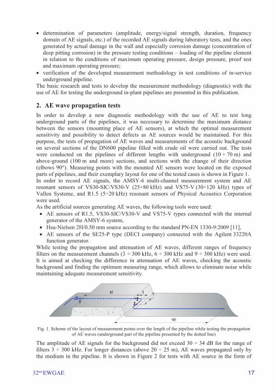
2. AE wave propagation tests In order to develop a new diagnostic methodology with the use of AE to test long underground parts of the pipelines, it was necessary to determine the maximum distance between the sensors (mounting place of AE sensors), at which the optimal measurement sensitivity and possibility to detect defects as AE sources would be maintained. For this purpose, the tests of propagation of AE waves and measurements of the acoustic background on several sections of the DN600 pipeline filled with crude oil were carried out. The tests were conducted on the pipelines of different lengths with underground (10 ÷ 70 m) and above-ground (100 m and more) sections, and sections with the change of their direction (elbows 90°). Measuring points with the mounted AE sensors were located on the exposed parts of pipelines, and their exemplary layout for one of the tested cases is shown in Figure 1. In order to record AE signals, the AMSY-6 multi-channel measurement system and AE resonant sensors of VS30-SIC/VS30-V (25÷80 kHz) and VS75-V (30÷120 kHz) types of Vallen Systeme, and R1.5 (5÷20 kHz) resonant sensors of Physical Acoustics Corporation were used. As the artificial sources generating AE waves, the following tools were used:
• AE sensors of R1.5, VS30-SIC/VS30-V and VS75-V types connected with the internal generator of the AMSY-6 system,
• Hsu-Nielsen 2H/0.50 mm source according to the standard PN-EN 1330-9:2009 [11], • AE sensors of the SE25-P type (DECI company) connected with the Agilent 33220A
function generator. While testing the propagation and attenuation of AE waves, different ranges of frequency filters on the measurement channels (3 ÷ 300 kHz, 6 ÷ 300 kHz and 9 ÷ 300 kHz) were used. It is aimed at checking the difference in attenuation of AE waves, checking the acoustic background and finding the optimum measuring range, which allows to eliminate noise while maintaining adequate measurement sensitivity.
Fig. 1. Scheme of the layout of measurement points over the length of the pipeline while testing the propagation
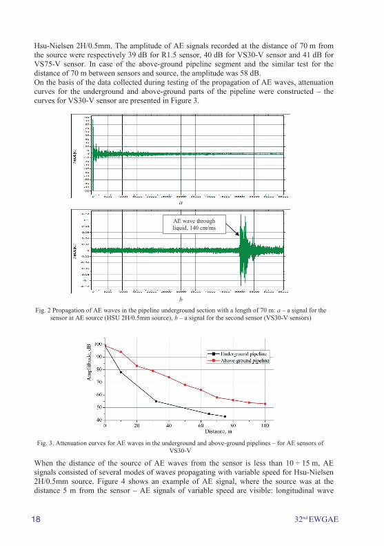
of AE waves (underground part of the pipeline presented by the dotted line) The amplitude of AE signals for the background did not exceed 30 ÷ 34 dB for the range of filters 3 ÷ 300 kHz. For longer distances (above 20 ÷ 25 m), AE waves propagated only by the medium in the pipeline. It is shown in Figure 2 for tests with AE source in the form of
18 32nd EWGAE
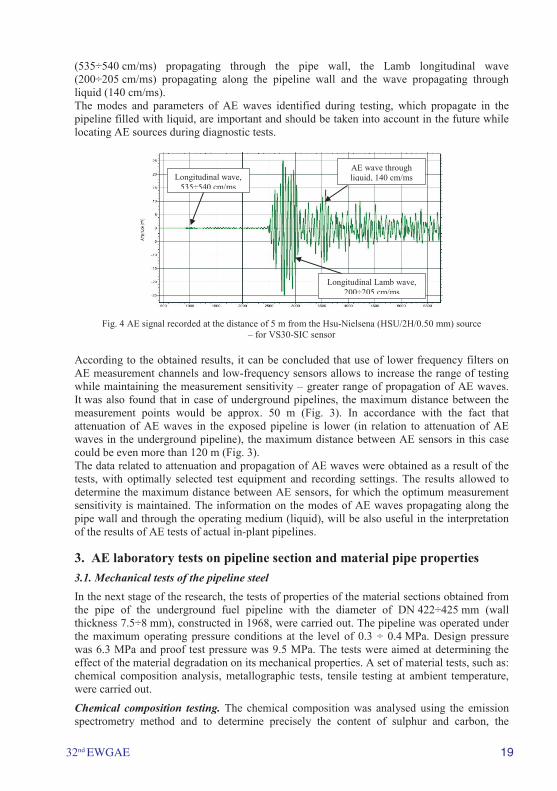
Hsu-Nielsen 2H/0.5mm. The amplitude of AE signals recorded at the distance of 70 m from the source were respectively 39 dB for R1.5 sensor, 40 dB for VS30-V sensor and 41 dB for VS75-V sensor. In case of the above-ground pipeline segment and the similar test for the distance of 70 m between sensors and source, the amplitude was 58 dB. On the basis of the data collected during testing of the propagation of AE waves, attenuation curves for the underground and above-ground parts of the pipeline were constructed – the curves for VS30-V sensor are presented in Figure 3.
a
b
Fig. 2 Propagation of AE waves in the pipeline underground section with a length of 70 m: a – a signal for the sensor at AE source (HSU 2H/0.5mm source), b – a signal for the second sensor (VS30-V sensors)
Fig. 3. Attenuation curves for AE waves in the underground and above-ground pipelines – for AE sensors of
VS30-V
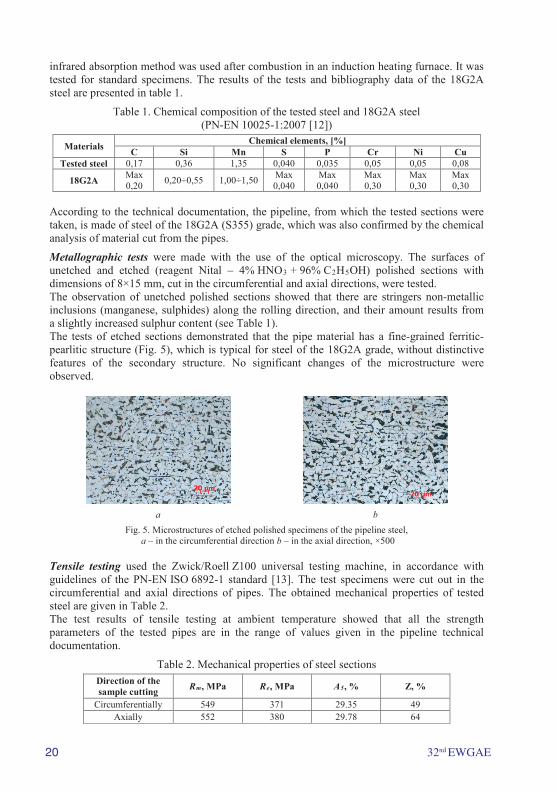
When the distance of the source of AE waves from the sensor is less than 10 ÷ 15 m, AE signals consisted of several modes of waves propagating with variable speed for Hsu-Nielsen 2H/0.5mm source. Figure 4 shows an example of AE signal, where the source was at the distance 5 m from the sensor – AE signals of variable speed are visible: longitudinal wave
AE wave through liquid, 140 cm/ms
32nd EWGAE 19
(535÷540 cm/ms) propagating through the pipe wall, the Lamb longitudinal wave (200÷205 cm/ms) propagating along the pipeline wall and the wave propagating through liquid (140 cm/ms). The modes and parameters of AE waves identified during testing, which propagate in the pipeline filled with liquid, are important and should be taken into account in the future while locating AE sources during diagnostic tests.
Fig. 4 AE signal recorded at the distance of 5 m from the Hsu-Nielsena (HSU/2H/0.50 mm) source – for VS30-SIC sensor
According to the obtained results, it can be concluded that use of lower frequency filters on AE measurement channels and low-frequency sensors allows to increase the range of testing while maintaining the measurement sensitivity – greater range of propagation of AE waves. It was also found that in case of underground pipelines, the maximum distance between the measurement points would be approx. 50 m (Fig. 3). In accordance with the fact that attenuation of AE waves in the exposed pipeline is lower (in relation to attenuation of AE waves in the underground pipeline), the maximum distance between AE sensors in this case could be even more than 120 m (Fig. 3). The data related to attenuation and propagation of AE waves were obtained as a result of the tests, with optimally selected test equipment and recording settings. The results allowed to determine the maximum distance between AE sensors, for which the optimum measurement sensitivity is maintained. The information on the modes of AE waves propagating along the pipe wall and through the operating medium (liquid), will be also useful in the interpretation of the results of AE tests of actual in-plant pipelines.
3. AE laboratory tests on pipeline section and material pipe properties 3.1. Mechanical tests of the pipeline steel In the next stage of the research, the tests of properties of the material sections obtained from the pipe of the underground fuel pipeline with the diameter of DN 422÷425 mm (wall thickness 7.5÷8 mm), constructed in 1968, were carried out. The pipeline was operated under the maximum operating pressure conditions at the level of 0.3 ÷ 0.4 MPa. Design pressure was 6.3 MPa and proof test pressure was 9.5 MPa. The tests were aimed at determining the effect of the material degradation on its mechanical properties. A set of material tests, such as: chemical composition analysis, metallographic tests, tensile testing at ambient temperature, were carried out.
Chemical composition testing. The chemical composition was analysed using the emission spectrometry method and to determine precisely the content of sulphur and carbon, the
Longitudinal wave, 535÷540 cm/ms
AE wave through liquid, 140 cm/ms
Longitudinal Lamb wave, 200÷205 cm/ms
20 32nd EWGAE
infrared absorption method was used after combustion in an induction heating furnace. It was tested for standard specimens. The results of the tests and bibliography data of the 18G2A steel are presented in table 1.
Table 1. Chemical composition of the tested steel and 18G2A steel (PN-EN 10025-1:2007 [12])
Materials Chemical elements, [%] C Si Mn S P Cr Ni Cu
Tested steel 0,17 0,36 1,35 0,040 0,035 0,05 0,05 0,08
18G2A Max 0,20 0,20÷0,55 1,00÷1,50 Max
0,040 Max 0,040
Max 0,30
Max 0,30
Max 0,30
According to the technical documentation, the pipeline, from which the tested sections were taken, is made of steel of the 18G2A (S355) grade, which was also confirmed by the chemical analysis of material cut from the pipes.
Metallographic tests were made with the use of the optical microscopy. The surfaces of unetched and etched (reagent Nital – 4% HNO3 + 96% C2H5OH) polished sections with dimensions of 8×15 mm, cut in the circumferential and axial directions, were tested. The observation of unetched polished sections showed that there are stringers non-metallic inclusions (manganese, sulphides) along the rolling direction, and their amount results from a slightly increased sulphur content (see Table 1). The tests of etched sections demonstrated that the pipe material has a fine-grained ferritic-pearlitic structure (Fig. 5), which is typical for steel of the 18G2A grade, without distinctive features of the secondary structure. No significant changes of the microstructure were observed.
a b
Fig. 5. Microstructures of etched polished specimens of the pipeline steel, a – in the circumferential direction b – in the axial direction, ×500
Tensile testing used the Zwick/Roell Z100 universal testing machine, in accordance with guidelines of the PN-EN ISO 6892-1 standard [13]. The test specimens were cut out in the circumferential and axial directions of pipes. The obtained mechanical properties of tested steel are given in Table 2. The test results of tensile testing at ambient temperature showed that all the strength parameters of the tested pipes are in the range of values given in the pipeline technical documentation.
Table 2. Mechanical properties of steel sections Direction of the sample cutting Rm, MPa Re, MPa A5, % Z, %
Circumferentially 549 371 29.35 49 Axially 552 380 29.78 64
32nd EWGAE 21
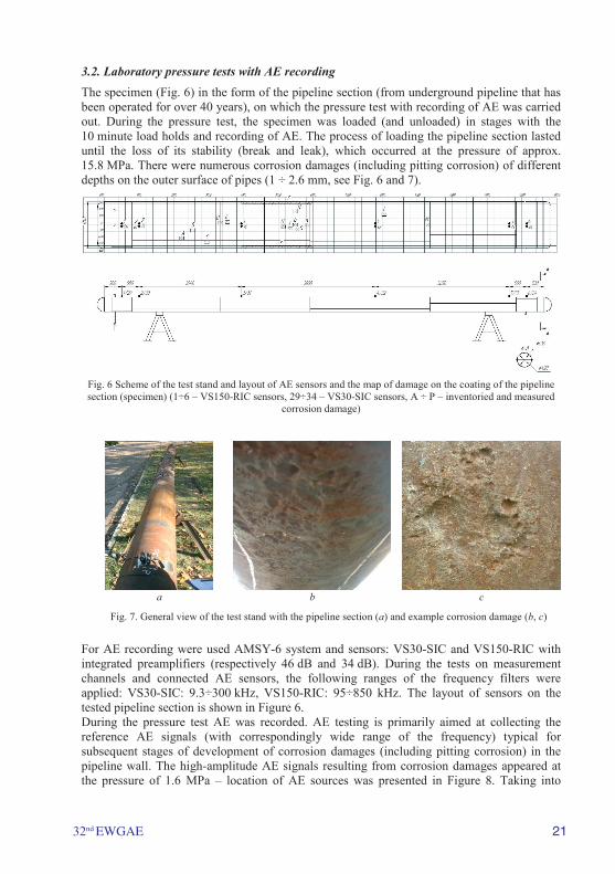
3.2. Laboratory pressure tests with AE recording The specimen (Fig. 6) in the form of the pipeline section (from underground pipeline that has been operated for over 40 years), on which the pressure test with recording of AE was carried out. During the pressure test, the specimen was loaded (and unloaded) in stages with the 10 minute load holds and recording of AE. The process of loading the pipeline section lasted until the loss of its stability (break and leak), which occurred at the pressure of approx. 15.8 MPa. There were numerous corrosion damages (including pitting corrosion) of different depths on the outer surface of pipes (1 ÷ 2.6 mm, see Fig. 6 and 7).
Fig. 6 Scheme of the test stand and layout of AE sensors and the map of damage on the coating of the pipeline section (specimen) (1÷6 – VS150-RIC sensors, 29÷34 – VS30-SIC sensors, A ÷ P – inventoried and measured
corrosion damage)
a b c
Fig. 7. General view of the test stand with the pipeline section (a) and example corrosion damage (b, c)
For AE recording were used AMSY-6 system and sensors: VS30-SIC and VS150-RIC with integrated preamplifiers (respectively 46 dB and 34 dB). During the tests on measurement channels and connected AE sensors, the following ranges of the frequency filters were applied: VS30-SIC: 9.3÷300 kHz, VS150-RIC: 95÷850 kHz. The layout of sensors on the tested pipeline section is shown in Figure 6. During the pressure test AE was recorded. AE testing is primarily aimed at collecting the reference AE signals (with correspondingly wide range of the frequency) typical for subsequent stages of development of corrosion damages (including pitting corrosion) in the pipeline wall. The high-amplitude AE signals resulting from corrosion damages appeared at the pressure of 1.6 MPa – location of AE sources was presented in Figure 8. Taking into
22 32nd EWGAE
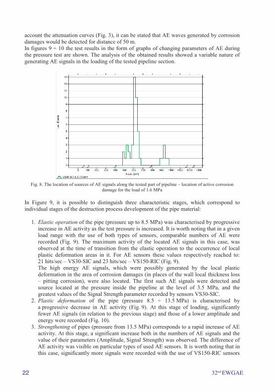
account the attenuation curves (Fig. 3), it can be stated that AE waves generated by corrosion damages would be detected for distance of 50 m. In figures 9 ÷ 10 the test results in the form of graphs of changing parameters of AE during the pressure test are shown. The analysis of the obtained results showed a variable nature of generating AE signals in the loading of the tested pipeline section.
Fig. 8. The location of sources of AE signals along the tested part of pipeline – location of active corrosion
damage for the load of 1.6 MPa
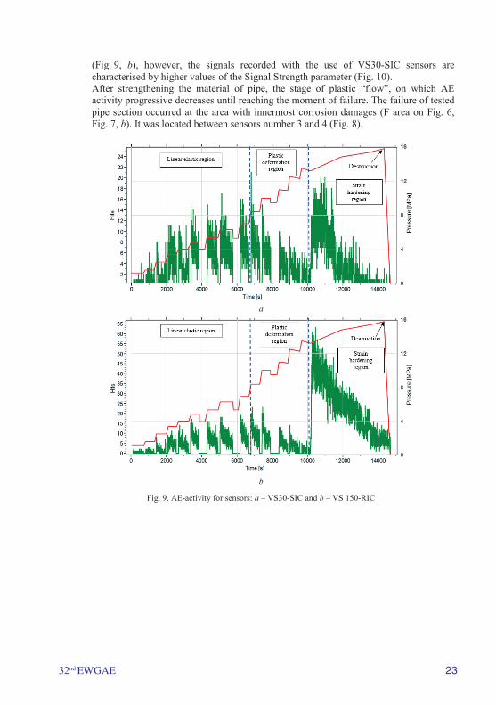
In Figure 9, it is possible to distinguish three characteristic stages, which correspond to individual stages of the destruction process development of the pipe material:
1. Elastic operation of the pipe (pressure up to 8.5 MPa) was characterised by progressive increase in AE activity as the test pressure is increased. It is worth noting that in a given load range with the use of both types of sensors, comparable numbers of AE were recorded (Fig. 9). The maximum activity of the located AE signals in this case, was observed at the time of transition from the elastic operation to the occurrence of local plastic deformation areas in it. For AE sensors these values respectively reached to: 21 hits/sec – VS30-SIC and 23 hits/sec – VS150-RIC (Fig. 9). The high energy AE signals, which were possibly generated by the local plastic deformation in the area of corrosion damages (in places of the wall local thickness loss – pitting corrosion), were also located. The first such AE signals were detected and source located at the pressure inside the pipeline at the level of 3.5 MPa, and the greatest values of the Signal Strength parameter recorded by sensors VS30-SIC.
2. Plastic deformation of the pipe (pressure 8.5 ÷ 13.5 MPa) is characterised by a progressive decrease in AE activity (Fig. 9). At this stage of loading, significantly fewer AE signals (in relation to the previous stage) and those of a lower amplitude and energy were recorded (Fig. 10).
3. Strengthening of pipes (pressure from 13.5 MPa) corresponds to a rapid increase of AE activity. At this stage, a significant increase both in the numbers of AE signals and the value of their parameters (Amplitude, Signal Strength) was observed. The difference of AE activity was visible on particular types of used AE sensors. It is worth noting that in this case, significantly more signals were recorded with the use of VS150-RIC sensors
32nd EWGAE 23
(Fig. 9, b), however, the signals recorded with the use of VS30-SIC sensors are characterised by higher values of the Signal Strength parameter (Fig. 10). After strengthening the material of pipe, the stage of plastic “flow”, on which AE activity progressive decreases until reaching the moment of failure. The failure of tested pipe section occurred at the area with innermost corrosion damages (F area on Fig. 6, Fig. 7, b). It was located between sensors number 3 and 4 (Fig. 8).
a
b
Fig. 9. AE-activity for sensors: a – VS30-SIC and b – VS 150-RIC
24 32nd EWGAE
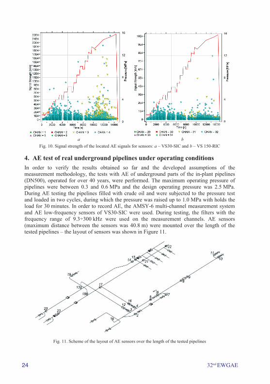
a b
Fig. 10. Signal strength of the located AE signals for sensors: a – VS30-SIC and b – VS 150-RIC
4. AE test of real underground pipelines under operating conditions In order to verify the results obtained so far and the developed assumptions of the measurement methodology, the tests with AE of underground parts of the in-plant pipelines (DN500), operated for over 40 years, were performed. The maximum operating pressure of pipelines were between 0.3 and 0.6 MPa and the design operating pressure was 2.5 MPa. During AE testing the pipelines filled with crude oil and were subjected to the pressure test and loaded in two cycles, during which the pressure was raised up to 1.0 MPa with holds the load for 30 minutes. In order to record AE, the AMSY-6 multi-channel measurement system and AE low-frequency sensors of VS30-SIC were used. During testing, the filters with the frequency range of 9.3÷300 kHz were used on the measurement channels. AE sensors (maximum distance between the sensors was 40.8 m) were mounted over the length of the tested pipelines – the layout of sensors was shown in Figure 11.
Fig. 11. Scheme of the layout of AE sensors over the length of the tested pipelines
32nd EWGAE 25
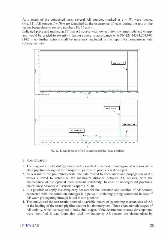
As a result of the conducted tests, several AE sources, marked as I ÷ IV, were located (Fig. 12). AE sources I ÷ III were identified as the occurrence of leaks during the test on the valves being close to sensors numbers 10, 16 and 4. Indicated place and marked as IV was AE source with low activity, low amplitude and energy and would be graded to severity 1 (minor source in accordance with PN-EN 14584:2013-07 [14]) – no further actions shall be necessary, included in the report for comparison with subsequent tests.
a
b
Fig. 12. Linear location of AE-sources along the tested pipelines
5. Conclusion 1. The diagnostic methodology based on tests with AE method of underground sections of in-
plant pipelines designed for transport of petroleum products is developed. 2. As a result of the preliminary tests, the data related to attenuation and propagation of AE
waves allowed to determine the maximum distance between AE sensors, with the maintenance of the optimal measurement sensitivity. In case of underground pipelines, the distance between AE sensors is approx. 50 m.
3. It is possible to apply low-frequency sensors for the detection and location of AE sources connected with the corrosion damages in pipe wall (including pitting corrosion) in case of AE wave propagating through liquid inside pipelines.
4. The analysis of the test results showed a variable nature of generating mechanisms of AE in the loading of the tested pipeline section in laboratory test. Three characteristic stages of AE activity, which correspond to individual stages of the destruction process development, were identified. It was found that used low-frequency AE sensors are characterised by
26 32nd EWGAE
increased sensitivity for detection of the local plastic deformation and material degradation due to corrosion, which cause local weakening of the pipeline material. These AE sensors also are suitable for leak testing.
5. It was also found that the high-amplitude AE signals, recorded at the pressure of 1.6 MPa, was generated by local corrosion damage (pitting corrosion), which are located on the pipeline wall. Taking into account the attenuation curves, it can be stated that AE waves generated by corrosion damage would be detected from the distance of 50 m.
6. In order to verify the developed diagnostic methodology, the tests of real underground parts of the pipelines (DN500), operated for more than 40 years, were performed. As a result of the tests, several AE sources, identified as the valves leaks, were located.
References [1] Sokólski W. Corrosion Processes Direct Assessment as a Part Of Operational Pipeline Safety’s, VIII National Conference Corrosion Measurements in Electrochemical Protection 16-18. jul 2004 Jurata, Poland. [2] Ming-Der Yang, Tung-Ching Su, Tung-Yen Wu and Kai-Siang Huang, Journal of GeoEngineering, 5 (3) (2010) 99–104. [3] Sunil K. Sinha, Mark A. Knight Intelligent System for Condition Monitoring of Underground Pipelines, Computer-Aided Civil and Infrastructure Eng., 19 (2004) 42–53. [4] Demma A., Alleyne D., Pavlakovic B., Testing of Buried Pipelines Using Guided Waves, Middle East Nondestructive Testing Conference & Exhibition – 27-30 Nov. 2005 Bahrain. [5] Francisco C. R. Marques, Alessandro Demma, Ultrasonic Guided Waves Evaluation of Trials for Pipeline Inspection, 17th World Conference on Nondestructive Testing, 25-28 Oct. 2008, Shanghai, China. [6] Pollock A.A., and Hsu S.-Y.S., Leak Detection Using Acoustic Emission, Journal of Acoustic Emission, 1 (4) 1982 237–243. [7] Shifeng Liu, Luming Li, Jian Cui, Tie Li Acoustic Emission Detection of Underground Pipeline Leakage 15th WCNDT, 2000, Roma, Itally. [8] Anastasopoulos A., Kourousis D., Bollas K., at all. Acoustic Emission Leak Detection of Buried Pipeline, 19th Intl AE Symposium (IAES19), Kyoto, Japan, 8-12 Dec., 2008. [9] Bui Van Hieu, Seunghwan Choi, Young Uk Kim,, Youngsuk Park and Taikyeong Jeong, Wireless Transmission of Acoustic Emission Signals for Real-Time Monitoring of Leakage in Underground Pipes, Journal of Civil Engineering 15 (5) (2011) 805–812. [10] Juliano T. M., Meegoda J. N., Watts D. J. Acoustic Emission Leak Detection on a Metal Pipeline Buried in Sandy Soil, Journal of Pipeline Systems Engineering and Practice, 4(3) (2013) 149-155. [11] PN-EN 1330-9:2009 „Non-destructive testing – Terminology – Part 9: Terms used in acoustic emission testing”. [12] PN-EN 10025-1:2007 „Hot Rolled Products Of Structural Steels – Part 1: General Technical Delivery Conditions”. [13] PN-EN ISO 6892-1 „Metallic materials – Tensile testing – Part 1: Method of test at ambient temperature”. [14] PN-EN 14584:2013-07 „Non-destructive testing – Acoustic Emission Testing – Examination of metallic pressure equipment during proof testing – Planar location of AE sources”.