Acelerated Precast Bridges PCI
102
PCI NORTHEAST BRIDGE TECHNICAL COMMITTEE GUIDELINES FOR ACCELERATED BRIDGE CONSTRUCTION USING PRECAST/PRESTRESSED CONCRETE COMPONENTS
-
Upload
aleitaosilva -
Category
Documents
-
view
1.360 -
download
6
description
Civil engineering
Transcript of Acelerated Precast Bridges PCI

PCI NORTHEAST BRIDGE TECHNICAL COMMITTEE
GUIDELINES FOR ACCELERATED BRIDGE CONSTRUCTION USING PRECAST/PRESTRESSED CONCRETE COMPONENTS


GUIDELINES FOR ACCELERATED BRIDGE CONSTRUCTION USING
PRECAST/PRESTRESSED CONCRETE COMPONENTS
PCINER-06-ABC
First Edition
Cover Photo: Davis Narrows Bridge courtesy of the Maine Department of Transportation
116 Radcliffe Road | Belmont, MA 02478
Phone (888) 700-5670 | http://www.pcine.org

PCINER-06-ABC Copyright © 2006 By Precast/Prestressed Concrete Institute Northeast First Edition, first printing, 2006 All rights reserved. This guide or any part thereof may not be reproduced in any form without the written permission of the Precast/Prestressed Concrete Institute Northeast. Information contain in this work has been obtained from sources believed to be reliable. PCI or its memberships shall not be responsible for any errors, omissions or damages arising out of this information. PCI has published this work with the understanding that PCI is supplying information only. PCI is not rendering engineering or other professional services through this guideline. If such services are required, please seek an appropriate professional. Printed in the U.S.A

FORWARD This manual has been developed for the purposes of promoting a greater degree of uniformity among owners, engineers and industry of the Northeast, with respect to planning, designing, fabricating and constructing highway bridges with the FHWA’s philosophy of accelerated bridge construction. In response to needs determined by Northeast Transportation Agencies, and Prestressed Concrete Producers, the PCI Northeast Regional Bridge Technical Committee established a subcommittee comprised of a cross section of its members representing academia, transportation engineers and producers to prepare this guide. Contributors were: Accelerated Bridge Construction Sub Committee:
Rita Seraderian, PCI Northeast Executive Director (PCINE) Michael P. Culmo, Vice President of Transportation and Structures, CME Associates, Inc. Peter Stamnas, Project Manager, New Hampshire Department of Transportation (NHDOT) Charles Goodspeed, University of New Hampshire, FHWA Eric Calderwood, Principal, Calderwood Engineering etc. George W. Colgrove III, Project Engineer, Vermont Agency of Transportation (VTrans) The PCI-NE Bridge Tech Committee: Eric Thorkildsen, Collins Engineering Vartan Sahakian, Commonwealth Eng. & Consult. Joe Carrara, J. P. Carrara & Sons Ernie Brod, J. P. Carrara & Sons Ed Barwicki, Lin Associates Michael Kane, Mabey Bridge Nate Benoit, Maine DOT Robert Bulger, Maine DOT Maura Sullivan, Mass. Highway Department Alex Bardow, Mass. Highway Department Edmund Newton, Mass. Highway Department David Scott, New Hampshire DOT Duane Carpenter, NYSDOT Matthew Royce, NYSDOT Mike Savella, State of Rhode Island DOT
PCI – NORTHEAST TECHNICAL BRIDGE COMMITTEE v

PCI – NORTHEAST TECHNICAL BRIDGE COMMITTEE vi

TABLE OF CONTENTS FORWARD............................................................................................................................................................ V TABLE OF CONTENTS.....................................................................................................................................VII INTRODUCTION................................................................................................................................................. XI SECTION 1: APPLICATION OVERVIEW .......................................................................................................1-1
1.1 When to Use Accelerated Construction..............................................................................................1-1 1.2 Rehabilitation PROJECTS..................................................................................................................1-2 1.3 Examples of Prefabricated Components.............................................................................................1-2 1.4 Architectural Treatments ....................................................................................................................1-5 1.5 Definitions ..........................................................................................................................................1-5
SECTION 2: GENERAL REQUIREMENTS .....................................................................................................2-1 2.1 PARTIAL REPLACEMENT PROJECTS .........................................................................................2-1 2.2 Design .................................................................................................................................................2-1 2.3 Geometric Configurations...................................................................................................................2-1
2.3.1 Bridge Layout.................................................................................................................................2-1 2.3.2 Component Sizes and Shapes.........................................................................................................2-2
2.4 Tolerances...........................................................................................................................................2-2 2.5 Shipping and Handling .......................................................................................................................2-2
2.5.1 Lifting Devices ...............................................................................................................................2-3 SECTION 3: PRECAST COMPONENTS ..........................................................................................................3-1
3.1 Piling...................................................................................................................................................3-1 3.2 Substructure Components ...................................................................................................................3-1
3.2.1 Footings ..........................................................................................................................................3-1 3.2.1.1 Construction on Bedrock ...........................................................................................................3-1 3.2.1.2 Construction on Soil...................................................................................................................3-2 3.2.1.3 Construction on Piles .................................................................................................................3-3 3.2.1.4 Leveling Devices........................................................................................................................3-3 3.2.1.5 Grouting Under Footings ...........................................................................................................3-4
3.2.2 Wall Segments................................................................................................................................3-4 3.2.3 Columns..........................................................................................................................................3-6
3.2.3.1 Round vs. Rectangular ...............................................................................................................3-6 3.2.4 Girder Support Components...........................................................................................................3-6
3.2.4.1 Pier Caps ....................................................................................................................................3-7 3.2.4.2 Integral Abutment Pile Caps ......................................................................................................3-7 3.2.4.3 Seat Adjustment Beams .............................................................................................................3-8
3.3 Superstructure Components................................................................................................................3-9 3.3.1 Girders and Beams .........................................................................................................................3-9 3.3.2 Full Depth Deck Slabs....................................................................................................................3-9 3.3.3 Stay-in-Place Forms .....................................................................................................................3-10
3.4 PROPRIETARY Bridge Systems.....................................................................................................3-11 3.5 Bridge Railing...................................................................................................................................3-11
SECTION 4: JOINTS ..........................................................................................................................................4-1 4.1 General................................................................................................................................................4-1 4.2 Layout of Joints ..................................................................................................................................4-1 4.3 Structural Joints ..................................................................................................................................4-2
4.3.1 Moment Connections .....................................................................................................................4-2 PCI – NORTHEAST TECHNICAL BRIDGE COMMITTEE vii

4.3.2 Shear Connections..........................................................................................................................4-3 4.3.3 Pile Connections.............................................................................................................................4-5 4.3.4 Anchoring Devices .........................................................................................................................4-7
4.4 Non-Structural Joints ..........................................................................................................................4-8 SECTION 5: GROUTING...................................................................................................................................5-1
5.1 Sub-Footings.......................................................................................................................................5-1 5.2 Component to Component grouting ...................................................................................................5-1
5.2.1 Horizontal Surfaces ........................................................................................................................5-1 5.2.1.1 Area Below Precast Footings .....................................................................................................5-1 5.2.1.2 Recessed Key Connection..........................................................................................................5-1 5.2.1.3 Recommended Grouting Procedure ...........................................................................................5-2 5.2.1.4 Non Recessed Connection .........................................................................................................5-3
5.2.2 Vertical Surfaces ............................................................................................................................5-3 5.2.3 Mechanical Grouted Splices...........................................................................................................5-3
5.3 Pile Caps .............................................................................................................................................5-4 5.4 Post Tensioning Ducts ........................................................................................................................5-4 5.5 Blockouts for Anchoring Devices.......................................................................................................5-5
SECTION 6: SEISMIC CONSIDERATIONS ....................................................................................................6-1 6.1 General Criteria ..................................................................................................................................6-1 6.2 Connection of Superstructure to Substructure ....................................................................................6-1
6.2.1 Keeper Blocks ................................................................................................................................6-1 6.2.2 Pilasters ..........................................................................................................................................6-2 6.2.3 Abutment Backwall ........................................................................................................................6-2 6.2.4 Anchor Rods...................................................................................................................................6-2 6.2.5 Integral Connections.......................................................................................................................6-3
6.3 Column Connections ..........................................................................................................................6-3 6.3.1 Column Base and Cap Connections ...............................................................................................6-3 6.3.2 Splices Along Column Length .......................................................................................................6-4 6.3.3 Confinement Reinforcement ..........................................................................................................6-5
6.4 Footings ..............................................................................................................................................6-5 6.4.1 Internal reinforcement ....................................................................................................................6-5 6.4.2 Pile Uplift .......................................................................................................................................6-5
SECTION 7: FABRICATION/CONSTRUCTION .............................................................................................7-1 7.1 Contractor Options..............................................................................................................................7-1 7.2 Lifting Devices ...................................................................................................................................7-1
7.2.1 Corrosion Protection.......................................................................................................................7-1 7.3 Equipment...........................................................................................................................................7-1
7.3.1 Handling and Shipping...................................................................................................................7-1 7.3.2 Skidding..........................................................................................................................................7-1
7.4 Assembly Plan ....................................................................................................................................7-2 7.5 Coordination .......................................................................................................................................7-2 7.6 Tolerances...........................................................................................................................................7-3
7.6.1 Fabrication......................................................................................................................................7-3 7.6.2 Vertical Control in the Field...........................................................................................................7-3 7.6.3 Horizontal Control in the Field.......................................................................................................7-3
7.7 Inspection............................................................................................................................................7-3 7.7.1 Grouting of Horizontal Post-Tensioning Ducts..............................................................................7-3 7.7.2 Mechanical Grouted Splices...........................................................................................................7-4
7.8 Backfill ...............................................................................................................................................7-4 7.8.1 Flowable Fill...................................................................................................................................7-4 7.8.2 Compacted Granular Fill ................................................................................................................7-4
PCI – NORTHEAST TECHNICAL BRIDGE COMMITTEE viii

7.8.3 Foam Products................................................................................................................................7-4 SECTION 8: CASE STUDY 1, UPTON, MAINE..............................................................................................8-1 SECTION 9: CASE STUDY 2, BROOKSVILLE, MAINE................................................................................9-1 SECTION 10: CASE STUDY 3, EPPING, NEW HAMPSHIRE .......................................................................... 1 REFERENCES.................................................................................................................................................... R-1 INDEX ..................................................................................................................................................................I-1
PCI – NORTHEAST TECHNICAL BRIDGE COMMITTEE ix

PCI – NORTHEAST TECHNICAL BRIDGE COMMITTEE x
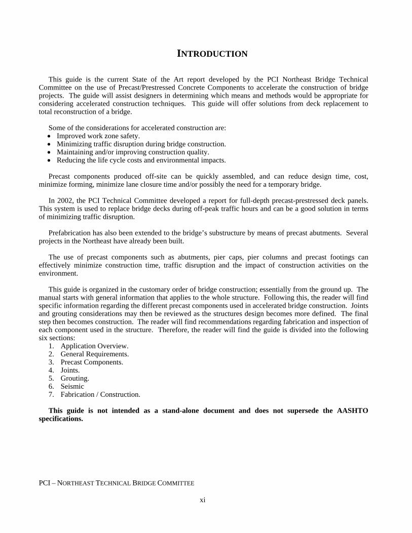
INTRODUCTION This guide is the current State of the Art report developed by the PCI Northeast Bridge Technical
Committee on the use of Precast/Prestressed Concrete Components to accelerate the construction of bridge projects. The guide will assist designers in determining which means and methods would be appropriate for considering accelerated construction techniques. This guide will offer solutions from deck replacement to total reconstruction of a bridge.
Some of the considerations for accelerated construction are: • Improved work zone safety. • Minimizing traffic disruption during bridge construction. • Maintaining and/or improving construction quality. • Reducing the life cycle costs and environmental impacts. Precast components produced off-site can be quickly assembled, and can reduce design time, cost,
minimize forming, minimize lane closure time and/or possibly the need for a temporary bridge. In 2002, the PCI Technical Committee developed a report for full-depth precast-prestressed deck panels.
This system is used to replace bridge decks during off-peak traffic hours and can be a good solution in terms of minimizing traffic disruption.
Prefabrication has also been extended to the bridge’s substructure by means of precast abutments. Several
projects in the Northeast have already been built. The use of precast components such as abutments, pier caps, pier columns and precast footings can
effectively minimize construction time, traffic disruption and the impact of construction activities on the environment.
This guide is organized in the customary order of bridge construction; essentially from the ground up. The
manual starts with general information that applies to the whole structure. Following this, the reader will find specific information regarding the different precast components used in accelerated bridge construction. Joints and grouting considerations may then be reviewed as the structures design becomes more defined. The final step then becomes construction. The reader will find recommendations regarding fabrication and inspection of each component used in the structure. Therefore, the reader will find the guide is divided into the following six sections:
1. Application Overview. 2. General Requirements. 3. Precast Components. 4. Joints. 5. Grouting. 6. Seismic 7. Fabrication / Construction. This guide is not intended as a stand-alone document and does not supersede the AASHTO
specifications.
PCI – NORTHEAST TECHNICAL BRIDGE COMMITTEE xi

PCI – NORTHEAST TECHNICAL BRIDGE COMMITTEE xii

GUIDELINES FOR ACCELERATED BRIDGE CONSTRUCTION USING PRECAST/PRESTRESSED CONCRETE COMPONENTS 1-1
PCI – NORTHEAST TECHNICAL BRIDGE COMMITTEE
SECTION 1: APPLICATION OVERVIEW
1.1 WHEN TO USE ACCELERATED CONSTRUCTION
Accelerated construction techniques should be used where the benefits of accelerated construction have a positive effect on the construction costs and impacts of the project. In many cases accelerated construction techniques can reduce overall project costs. At this time, the bridge specific costs on small accelerated construction projects are more than conventional construction (This is not necessarily the case with large scale projects.) It is also anticipated that costs will come down as more accelerated projects are let. The savings in accelerated construction projects are found in other aspects of the project such as time, equipment use and labor savings.
Decisions to use accelerated construction techniques should be made after considering the following issues: • Temporary Roadways and Bridges • Reductions in Environmental Impacts • User Costs • Political Pressures • Long Detours
For additional guidance, refer to the Federal Highway Administration report entitled “Decision-Making Framework for Prefabricated Bridge Elements and Systems (PBES), May 2006”.
Accelerated construction should always be considered in cases where temporary bridges and roadways are
anticipated. This is especially true where a reasonable detour is available. It may be desirable to close a roadway completely, build the bridge quickly, and live with a detour. In this case, the cost of the accelerated construction is far outweighed by the savings of not building a temporary roadway. Recent accelerated construction projects have shown that commuters and businesses prefer a significant short-term impact over a long-term moderate impact.
For bridges over water courses, impacts to the environment can be lessened by the elimination of a
temporary bridge. The cost of construction to highway users is significant. Savings to commuters are not typically reflected in
construction budgets for highway projects; however there is a significant financial impact to the entire community due to travel delays. In many cases, the cost of accelerated construction techniques can be offset by reductions in user costs.
Often the need for accelerated construction can be driven by political pressures. The impacts of
construction on commuters and businesses in urban areas can be devastating. Accelerated construction can be used to limit the time frames for construction projects in these areas.
On some projects, the use of staging and temporary bridges is not feasible due to limited right of way and
environmental issues. In these cases detours are the only option. Accelerated construction techniques should be considered if there are issues with traffic volumes on detours and access for emergency vehicles.
Though the intent of this manual is to provide information that applies to precast/prestressed components
used in bridge construction, using these components in non-prestress concrete structures is encouraged. The designer may wish to use precast substructure with steel girders and precast deck panels for example.

GUIDELINES FOR ACCELERATED BRIDGE CONSTRUCTION USING 1-2 PRECAST/PRESTRESSED CONCRETE COMPONENTS
PCI – NORTHEAST TECHNICAL BRIDGE COMMITTEE
1.2 REHABILITATION PROJECTS
Many bridge rehabilitation projects may benefit from accelerated construction methods. This guide focuses on precast components that could replace the entire bridge; however portions of existing bridges can also be constructed using these methods. The designer in these cases should balance the cost savings of not constructing new components to the costs of rehabilitating existing components. Costs should include both financial resources and time.
1.3 EXAMPLES OF PREFABRICATED COMPONENTS
Prefabricated components in accelerated bridge construction are comprised of separately shipped pieces which are assembled in the field to form a larger structural component of the completed bridge. Figure 1.3-1 and Figure 1.3-2 are examples of what components are used to construct a pier and a bridge deck. Figure 1.3-3 and Figure 1.3-4 further demonstrates the assembly of an abutment structural component and the superstructure. Figure 1.3-5 demonstrates what components are necessary to assemble an integral abutment bridge.
Figure 1.3-6 shows the assembly completed.
Pier Cap [ 3.2.4.1 ]
Moment Connection [ 4.3.1 ] Anchoring Devices [ 4.3.4 ]
Column [ 3.2.3 ]
Footing [ 3.2.1 ]
Figure 1.3-1 Assembly of Substructure Prefabricated Components
GUIDELINES FOR ACCELERATED BRIDGE CONSTRUCTION USING PRECAST/PRESTRESSED CONCRETE COMPONENTS 1-3
PCI – NORTHEAST TECHNICAL BRIDGE COMMITTEE
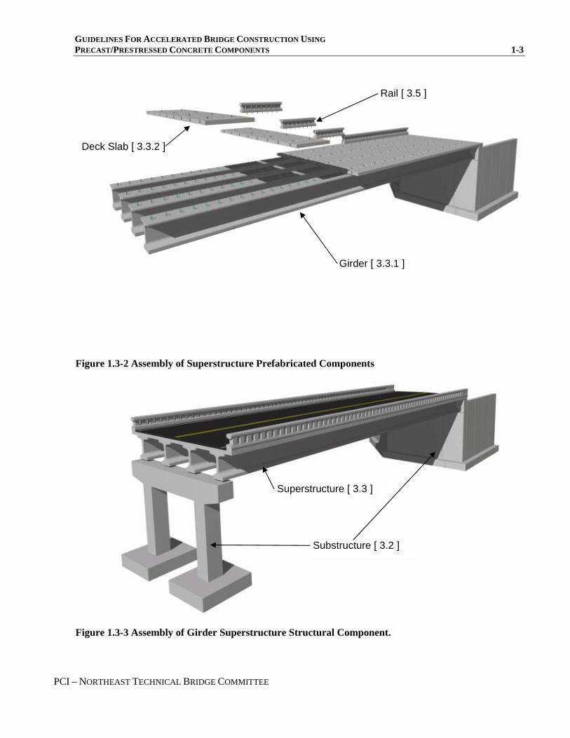
Figure 1.3-2 Assembly of Superstructure Prefabricated Components
Rail [ 3.5 ]
Deck Slab [ 3.3.2 ]
Girder [ 3.3.1 ]
Superstructure [ 3.3 ]
Substructure [ 3.2 ]
Figure 1.3-3 Assembly of Girder Superstructure Structural Component.
GUIDELINES FOR ACCELERATED BRIDGE CONSTRUCTION USING 1-4 PRECAST/PRESTRESSED CONCRETE COMPONENTS
PCI – NORTHEAST TECHNICAL BRIDGE COMMITTEE
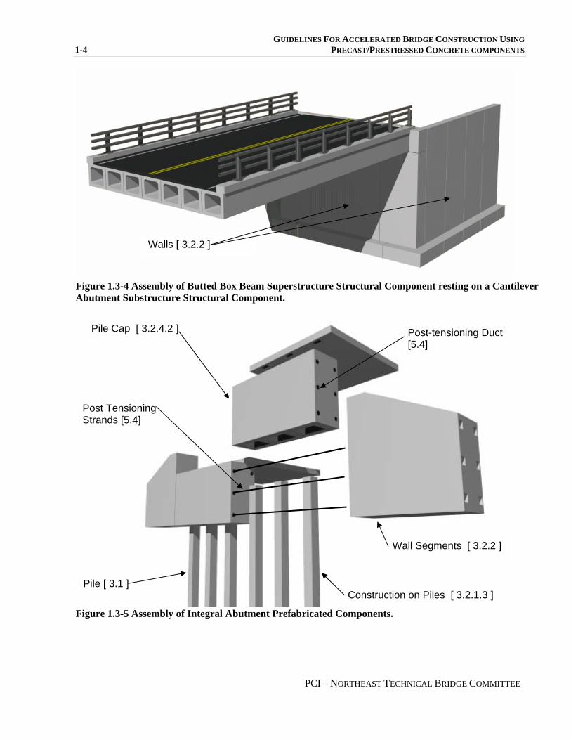
Walls [ 3.2.2 ]
Figure 1.3-4 Assembly of Butted Box Beam Superstructure Structural Component resting on a Cantilever Abutment Substructure Structural Component.
Figure 1.3-5 Assembly of Integral Abutment Prefabricated Components.
Construction on Piles [ 3.2.1.3 ]
Pile Cap [ 3.2.4.2 ]
Pile [ 3.1 ]
Wall Segments [ 3.2.2 ]
Post-tensioning Duct [5.4]
Post Tensioning Strands [5.4]

GUIDELINES FOR ACCELERATED BRIDGE CONSTRUCTION USING PRECAST/PRESTRESSED CONCRETE COMPONENTS 1-5
PCI – NORTHEAST TECHNICAL BRIDGE COMMITTEE
Figure 1.3-6 Full Assembly of Integral Abutment Structural Component supporting a Butted Box Beam Superstructure Structural Component..
1.4 ARCHITECTURAL TREATMENTS
An accelerated construction environment does not preclude the idea of having an attractive bridge. In fact the very opposite is the reality. With some careful planning, the resulting bridge can be built quickly, and also be aesthetically pleasing.
In most cases, cost will not be a limiting factor. Precast components allow for architectural enhancements
at a relatively lower cost than cast in place concrete. All treatments are made at the precast plant where repetitive use of standardized forms lowers the costs to individual projects. Precast plants are well suited for applying aggregate surfaces through means of blasting or the use of retardants.
Chapter 5 of the PCI Bridge Design Manual and the Minnesota Department of Transportation’s Aesthetic
Guidelines for Bridge Design offer guidance on this topic. These guidelines may be used to proportion components to fit together to meet the function of the structure as well as to enhance aesthetics.
1.5 DEFINITIONS
Box Beam – Rectangular shaped beam with a single rectangular shaped void. These beams have depths up to four feet and are used for short to moderate length spans. Prestressed strand is typically placed in the bottom flange in a 2 inch by 2 inch grid. Deck Slab – A solid and very slender slab that may be used for extremely short spans in the longitudinal direction or as a replacement for a cast-in-place deck over girders when placed transverse to the deck beams. Cast-in-Place – Concrete that is formed and placed in the field. Pile Cap – A structural component placed over piles which supports deck components. Prefabricated Component – A part of a larger structural component of a bridge such as a footing, column or

GUIDELINES FOR ACCELERATED BRIDGE CONSTRUCTION USING 1-6 PRECAST/PRESTRESSED CONCRETE COMPONENTS
PCI – NORTHEAST TECHNICAL BRIDGE COMMITTEE
wall. These components are fabricated offsite and shipped in separate pieces to the project site for eventual assembly. Precast Component – A structural component that is cast in a plant and shipped to the project site. Prestressed Component – A structural component that is cast with pretensioned steel strands causing compressive stresses in the component section. The compressive stresses are typically eccentric and are used to compensate for tensile stresses caused by loading of the component. Propriety Precast Products – Precast components that a single entity holds the patents to. These products tend to be specialized and may require special installation equipment or connectors. Accelerated Bridge Construction – A construction process that has been optimized for speed. Structural Component – A major part of a structure comprised of several precast components. Completed abutments or piers are examples of substructure structural components. The completed deck would be a superstructure structural component. Voided Slab – A rectangular beam shape with 2 or 3 circular voids running its length. These beams typically range in thickness from 15 inches to 21 inches. Prestressed strand is typically placed in the bottom flange in a 2 inch by 2 inch grid. Typically, these are used for very short spans.

GUIDELINES FOR ACCELERATED BRIDGE CONSTRUCTION USING PRECAST/PRESTRESSED CONCRETE COMPONENTS 2-1
PCI – NORTHEAST TECHNICAL BRIDGE COMMITTEE
SECTION 2: GENERAL REQUIREMENTS
Guidelines
Commentary
2.1 PARTIAL REPLACEMENT PROJECTS
If existing substructure is to be reused, complete dimensions and elevations should be obtained to ensure compatibility with the new precast components.
There is adjustability in precast components;
however the tolerances at interfaces are limited. The field survey is recommended.
2.2 DESIGN
A prefabricated system is designed using the same design approach as cast-in-place concrete structures.
In general, the design of precast substructures
involves emulation of traditional cast-in-place concrete structures with discrete precast components. The connections between components are designed to emulate traditional construction joints.
Designers may take advantage of post-
tensioning technologies to facilitate construction of complex structures.
The design and detailing of beams and girders
is generally not affected by accelerated construction techniques.
Providing a safe design to meet the site
requirements is paramount in all bridge replacement projects. Designs should not be compromised in order to utilize precast concrete structures. The engineer must focus on ease of fabrication, repetition, and ease of assembly to create a cost effective, precast concrete solution.
Designers should refer to the ACI 550.1R-01,
Emulating Cast-in-Place Detailing in Precast Concrete Structures for specifications on emulation design.
It may be advantageous to design complex
structures such as tall piers using post tensioning strand or high strength rods to simplify the connections.
2.3 GEOMETRIC CONFIGURATIONS
2.3.1 Bridge Layout
Non-skewed designs are preferred.
Angles between abutment and wingwalls
should be limited to in-line, and 90 degrees. Bridge skew angles should be minimized. In cases where they are unavoidable, the skew angle added to the wing angle should be kept to simple geometric angles such as 30, 45, and 60 degrees. Odd angles will complicate formwork and increase cost.

GUIDELINES FOR ACCELERATED BRIDGE CONSTRUCTION USING 2-2 PRECAST/PRESTRESSED CONCRETE COMPONENTS
PCI – NORTHEAST TECHNICAL BRIDGE COMMITTEE
Guidelines
Commentary
2.3.2 Component Sizes and Shapes
The designer should detail components sizes to promote repetition of forming with consideration given to transportation, fabrication and construction.
Battered components should be avoided.
Footing widths may be detailed such that there
are common dimensions on each bridge project. For instance on a particular bridge, all footings for wingwalls that are of approximately equal height could be kept identical (dimensions and reinforcing). The economies of repetition may outweigh the perceived benefits of individually sized components.
Batters on abutment and wing stems should be
eliminated and the overall thickness of the stems should be minimized to reduce the overall weight of the component. Components typically are cast horizontally as slabs.
2.4 TOLERANCES
Designers should specify and account for tolerances in layout of components.
Nominal joint widths should be set based on
the specified tolerances.
All precast concrete products are constructed
within a specified tolerance. Designers should refer to the PCI Tolerance Manual MNL 135-00 for guidance on setting appropriate tolerances for each component.
Base the layout of components on the
nominal center to center of joints as opposed to the actual component size.
At a minimum, the joint width should account
for the width tolerance and sweep tolerance of the components.
2.5 SHIPPING AND HANDLING
Precast substructure components should be detailed so that the pieces can be shipped using normal shipping equipment.
In special cases, very large pieces can be
detailed; however the shipping costs can be excessive.
The designer should consider each State’s
requirement for allowable shipping widths.
The weight of precast substructure components
weighing on the order of 30 tons should be anticipated.
It is possible to ship pieces in excess of 30
tons, however the equipment required and limitation of local bridge capacities may limit this. Off-loading of pieces can also be problematic. Larger pieces may be feasible if the pieces can be fabricated in close proximity to the bridge and shipped a short distance.
In general, components should have a
maximum width of 12 feet to avoid cost premiums typically associated with shipping of large components over the road. Components
GUIDELINES FOR ACCELERATED BRIDGE CONSTRUCTION USING PRECAST/PRESTRESSED CONCRETE COMPONENTS 2-3
PCI – NORTHEAST TECHNICAL BRIDGE COMMITTEE
Guidelines
Commentary
with widths in excess of 12 feet typically require special trucking permits, which can be supplied at a premium.
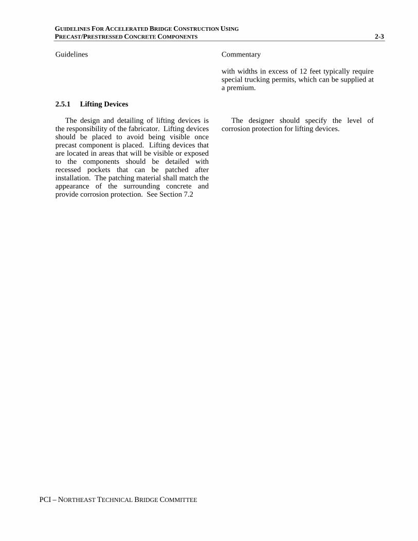
2.5.1 Lifting Devices
The design and detailing of lifting devices is the responsibility of the fabricator. Lifting devices should be placed to avoid being visible once precast component is placed. Lifting devices that are located in areas that will be visible or exposed to the components should be detailed with recessed pockets that can be patched after installation. The patching material shall match the appearance of the surrounding concrete and provide corrosion protection. See Section 7.2
The designer should specify the level of
corrosion protection for lifting devices.

GUIDELINES FOR ACCELERATED BRIDGE CONSTRUCTION USING 2-4 PRECAST/PRESTRESSED CONCRETE COMPONENTS
PCI – NORTHEAST TECHNICAL BRIDGE COMMITTEE

GUIDELINES FOR ACCELERATED BRIDGE CONSTRUCTION USING PRECAST/PRESTRESSED CONCRETE COMPONENTS 3-1
PCI – NORTHEAST TECHNICAL BRIDGE COMMITTEE
SECTION 3: PRECAST COMPONENTS
Guidelines
Commentary
3.1 PILING
The Designer may choose to use Precast prestressed concrete piles as an alternative to steel ‘H’-piles. Consult a Geotechnical Engineer for specific limitations regarding the project site before selecting the pile type and size.
Practice has shown that a minimum of 14 inch prestress pile sections has been successfully used in severe driving conditions. For more information regarding precast/prestressed concrete piles, refer to the PCI Bridge Design Manual BM-02-04 chapter 20.
3.2 SUBSTRUCTURE COMPONENTS
Substructure components include footings, wall segments, columns used in piers, and girder support beams.
3.2.1 Footings
The transfer of footing loads to the underlying soils should be made via a grout filled gap below the footings.
The bottom of the footings should be
roughened to a ¼” amplitude profile during fabrication.
It is unreasonable to assume that proper
interface can be achieved between compacted soil and a precast component. The unevenness of compacted soil combined with the tolerances of precast will lead to point of localized support. An effective means of providing this support is a grout-filled gap.
3.2.1.1 Construction on Bedrock A more extensive soils boring program should
precede construction of precast footings so that the degree of variation of top of rock elevations can be assessed prior to construction.
The uneven nature of construction of footings
on bedrock may require preparation of the site prior to installation of precast footings. Over-blasting of rock by approximately 12” to provide room to prepare for a relatively level work area is
As with any construction on bedrock, large
variations in rock elevations can affect the layout and design of precast substructure components. It may be desirable to step footings where rock variations are significant. The contractor will also need this information to plan the work. Unknowns in rock elevations are always difficult to address. It is essential that most of this be addressed prior to construction on an accelerated project. The owner should balance the need for more borings with cost constraints.
The reason for over-blasting is to ensure that
the removal of rock will be a one-time process, and the amount of post-blast clean-up removal will be kept to a minimum.

GUIDELINES FOR ACCELERATED BRIDGE CONSTRUCTION USING 3-2 PRECAST/PRESTRESSED CONCRETE COMPONENTS
PCI – NORTHEAST TECHNICAL BRIDGE COMMITTEE
Guidelines
Commentary
recommended. This will facilitate the installation of grout under the footings. See Section 3.2.1.5.
Once the area is made roughly level, there are two recommended methods for preparing the area for installation of precast footings. The first is to pour a low-strength concrete sub-footing to provide room for grouting. The second method is to provide small level concrete surfaces under the proposed leveling devices. See Section 3.2.1.4.
The concrete sub-footing need not be high
strength. The typical range of footing pressures are magnitudes less than the strength of the sub-footing concrete. The sub-footing concrete need not be formed. In most cases, the concrete can be cast against the footing excavation limits. Experience has shown that a low-strength concrete sub-footing does not slow construction and provides a very good work platform for installation of precast components.
3.2.1.2 Construction on Soil
Prior to construction on soil, the area must be excavated, and prepared as in normal cast-in-place construction.
Once the area is prepared, there are two
recommended methods for preparing the area for installation of precast footings. The first is to pour a low-strength concrete sub-footing to a level that is just below the proposed bottom of footing elevation as shown in Figure 3.2.1.2-1. The second method is to provide small level areas under the proposed leveling devices. See Section 3.2.1.4. Temporary load distribution plates will be required under the leveling devices when a sub-footing is not used in order to spread the loads to the soil.
See Section 3.2.1 commentary.
Figure 3.2.1.2-1 Placing footing segment on a sub-footing.

GUIDELINES FOR ACCELERATED BRIDGE CONSTRUCTION USING PRECAST/PRESTRESSED CONCRETE COMPONENTS 3-3
PCI – NORTHEAST TECHNICAL BRIDGE COMMITTEE
Guidelines
Commentary
Figure 3.2.1.2-2 Completed footing.
3.2.1.3 Construction on Piles Construction on piles will in general follow the
guidelines for construction on soil. A concrete sub-footing may be used, or the footing can be temporarily supported on load distribution plates on soil.
Provisions should be made in the footing
design for grouting of the areas around the pile tops. Grout placement is demonstrated in Figure 3.2.4.2.1-1 with an integral abutment section. A footing slab would be similar.
See Section 3.2.1 commentary.
3.2.1.3.1 Construction Clearances Provide clearance around each pile to account
for driving tolerances.
Six inches minimum clearance is
recommended. Refer to state standards for additional guidance.
3.2.1.4 Leveling Devices
Leveling devices are critical in maintaining proper vertical grade control on precast concrete substructures. Cast-in embedded leveling devices should be used to allow for adjustment of the footing grade and elevation during installation.
A minimum of four leveling devices should be
specified for each spread footing component. Each device should be designed to support half the self weight of the footing component.
The component should be leveled prior to
release of the piece from the crane. A thorough greasing of the leveling device is recommended.
Figure 3.2.1.4-1 shows a leveling screw detail.
Experience has shown that these leveling
devices provide fast and easy grade adjustment at a minimal cost. The use of leveling shim packs is discouraged since there is no way to adjust the grades without removing the component.
During installation, there is a tendency for the
piece to rock on the diagonal corner supports, therefore each device should be designed to support half the weight of the component.
The effort to adjust the leveling devices is
greatly reduced if the component is partially supported by the crane, or if it is greased.

GUIDELINES FOR ACCELERATED BRIDGE CONSTRUCTION USING 3-4 PRECAST/PRESTRESSED CONCRETE COMPONENTS
PCI – NORTHEAST TECHNICAL BRIDGE COMMITTEE
Guidelines
Commentary
Once the installation of the component is complete, the leveling bolt shall be backed out and the shaft filled with grout.
4"Ø BLOCKOUT
TAPERED BLOCKOUT
1"Ø BOLT PIPE SLEEVE
REMOVE BOLT AFTER
BASE HAS BEEN GROUTED.
GROUT BLOCKOUT AFTER
REMOVAL OF BOLT
REINFORCING
WELDED TO SUBFOOTING OR STRUCTURAL FILL
3" MIN. GROUT BED
LEDGE
LEVEL CONCRETE SUPPORT
Figure 3.2.1.4-1 Leveling Screw Detail 3.2.1.5 Grouting Under Footings
The purpose of grouting under spread footings is to distribute the foundation pressures from the precast footing to the underlying soil or rock. A gap that is grouted is recommended to achieve this. Exact grouting methods can be left up to the discretion of the general contractor. The plans and specifications should give certain guidelines on grouting procedures. See Section 5.
The strength of the grout is secondary to its
ability to properly fill the gap under the footing. The grout should be placed in the void through
ports cast in the footing. Attempting to flow the grout from one side to another is not recommended unless the footing is relatively narrow.
There are several methods that have been
successfully used. The contractor should be allowed to use a method that best suits the experience of the workers and the available equipment.
Footing pressures are magnitudes lower than
the compressive strength of grout; therefore strength of grout is not a concern. A minimum grout strength of 1000 psi is recommended.
Placement may be accomplished by pumping
or gravity feed through grout ports. The ports should be arranged so that the grouting operation progresses in a single general direction to avoid air pockets.
3.2.2 Wall Segments
There are several wall options available to designers for accelerated construction projects.
Designers should refer to each State’s
specifications for a listing of the approved

GUIDELINES FOR ACCELERATED BRIDGE CONSTRUCTION USING PRECAST/PRESTRESSED CONCRETE COMPONENTS 3-5
PCI – NORTHEAST TECHNICAL BRIDGE COMMITTEE
Guidelines
Commentary
Many States maintain approved proprietary precast concrete retaining wall systems. Another option is to use a precast concrete cantilever wall. The following options should be evaluated for each wall:
Precast Cantilever Mechanically Stabilized Earth (MSE) Precast Concrete Modular Block Gravity Wall
proprietary walls. Cantilever retaining walls can be detailed
using the techniques outlined in this guideline. The wall stems and footings can be made with precast concrete components. Often this type of wall will use the least amount of width (normal to wall face) when compared to other proprietary retaining wall systems.
Using precast facing panels in a MSE wall is
an ideal solution for accelerated construction. The wall facing, reinforcing strips and backfill can be constructed concurrently.
A precast concrete modular block gravity wall
is another ideal solution for accelerated construction. The blocks interlock using keys cast into them. The dead weight of the blocking system along with the interlocking keys eliminates the need for mechanical connections between precast units.
Figure 3.2.2-1 Placement of an abutment segments.
GUIDELINES FOR ACCELERATED BRIDGE CONSTRUCTION USING 3-6 PRECAST/PRESTRESSED CONCRETE COMPONENTS
PCI – NORTHEAST TECHNICAL BRIDGE COMMITTEE
Guidelines
Commentary
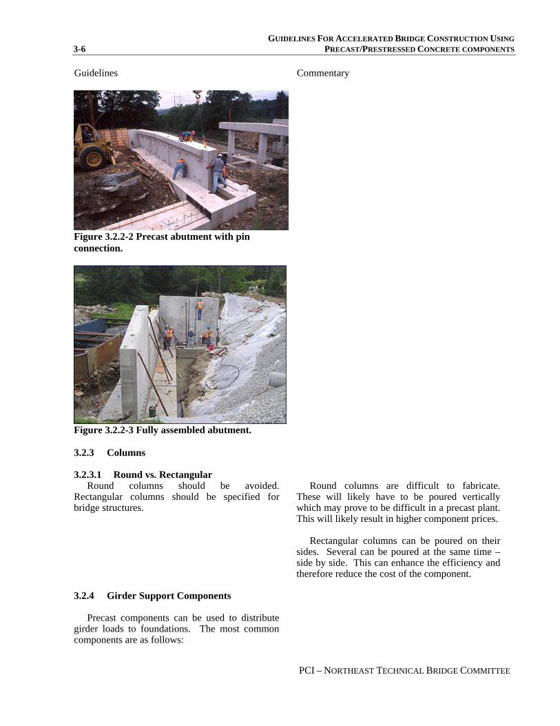
Figure 3.2.2-2 Precast abutment with pin connection.
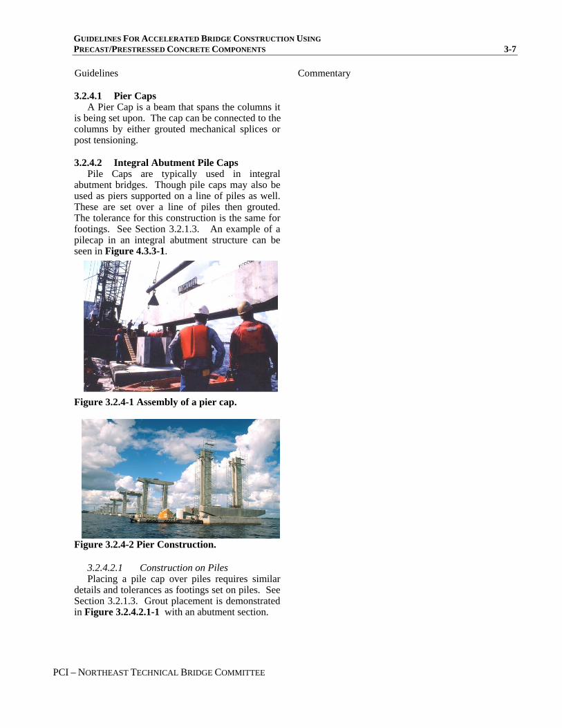
Figure 3.2.2-3 Fully assembled abutment.
3.2.3 Columns
3.2.3.1 Round vs. Rectangular Round columns should be avoided.
Rectangular columns should be specified for bridge structures.
Round columns are difficult to fabricate.
These will likely have to be poured vertically which may prove to be difficult in a precast plant. This will likely result in higher component prices.
Rectangular columns can be poured on their
sides. Several can be poured at the same time – side by side. This can enhance the efficiency and therefore reduce the cost of the component.
3.2.4 Girder Support Components
Precast components can be used to distribute girder loads to foundations. The most common components are as follows:
GUIDELINES FOR ACCELERATED BRIDGE CONSTRUCTION USING PRECAST/PRESTRESSED CONCRETE COMPONENTS 3-7
PCI – NORTHEAST TECHNICAL BRIDGE COMMITTEE
Guidelines
Commentary
3.2.4.1 Pier Caps A Pier Cap is a beam that spans the columns it
is being set upon. The cap can be connected to the columns by either grouted mechanical splices or post tensioning.
3.2.4.2 Integral Abutment Pile Caps Pile Caps are typically used in integral
abutment bridges. Though pile caps may also be used as piers supported on a line of piles as well. These are set over a line of piles then grouted. The tolerance for this construction is the same for footings. See Section 3.2.1.3. An example of a pilecap in an integral abutment structure can be seen in Figure 4.3.3-1.
Figure 3.2.4-1 Assembly of a pier cap.
Figure 3.2.4-2 Pier Construction.
3.2.4.2.1 Construction on Piles Placing a pile cap over piles requires similar
details and tolerances as footings set on piles. See Section 3.2.1.3. Grout placement is demonstrated in Figure 3.2.4.2.1-1 with an abutment section.

GUIDELINES FOR ACCELERATED BRIDGE CONSTRUCTION USING 3-8 PRECAST/PRESTRESSED CONCRETE COMPONENTS
PCI – NORTHEAST TECHNICAL BRIDGE COMMITTEE
Guidelines
Commentary
Figure 3.2.4.2.1-1 Concrete flow in Abutment Section
Packed Gravel, Sub-Footing or
Grout
Concrete Flow
Figure 3.2.4.2.1-2 Completed integral abutment assembly.
3.2.4.3 Seat Adjustment Beams Seat adjustment beams may be precast
according to field measurements. These beams may be used to elevate existing beam seat elevations on existing abutments. The beams are set on elastomeric sheets placed on the existing abutment. Figure 3.2.4.3-1 demonstrates the use of a seat adjustment beams to fill a portion of the abutment where deeper steel girders once sat.

GUIDELINES FOR ACCELERATED BRIDGE CONSTRUCTION USING PRECAST/PRESTRESSED CONCRETE COMPONENTS 3-9
PCI – NORTHEAST TECHNICAL BRIDGE COMMITTEE
Guidelines
Commentary
Figure 3.2.4.3-1 A Seat Adjustment Beam was placed on this abutment to level the bearing seats for the new deck units on this bridge rehabilitation.
3.3 SUPERSTRUCTURE COMPONENTS
3.3.1 Girders and Beams
Girders or beams shall be designed and detailed according to conventional methodology. Refer to the PCI Bridge Design Manual.
3.3.2 Full Depth Deck Slabs
Prefabricated decks offer advantages for deck construction since bridge components can be prefabricated offsite and assembled in place. Other advantages include removing the deck placement from the critical path of bridge construction schedules, cost savings, and increased quality due to controlled factory conditions. See Figure 3.3.2-1 .Figure 3.3.2-2 shows a typical placement of deck slabs.
Re-decking with prefabricated modular deck
panels is a viable method of deck replacement that minimizes traffic disruption. More importantly, this construction method allows opening part of the bridge under construction to traffic. In addition, nighttime re-decking with prefabricated concrete modular panels, although slightly more costly than daytime re-decking, can further minimize interruption of traffic. Also, the existing composite concrete deck could be replaced in stages. In each stage, a portion of the transverse section is removed and replaced along the full length of the bridge, while other lanes are maintained open for traffic.
General information on full depth deck slabs is presented here. For more information, refer to “Design Guidelines for the use of Full Depth Precast Deck Slabs used for new construction or for replacement of existing decks on bridges.” This document is available at the PCI Northeast website (www.pcine.org).

GUIDELINES FOR ACCELERATED BRIDGE CONSTRUCTION USING 3-10 PRECAST/PRESTRESSED CONCRETE COMPONENTS
PCI – NORTHEAST TECHNICAL BRIDGE COMMITTEE
Guidelines
Commentary
Figure 3.3.2-1 Schematic of precast deck assembly
Figure 3.3.2-2 Placing Deck Slabs 3.3.3 Stay-in-Place Forms
In situations where a cast-in-place deck will be necessary, precast stay-in-place concrete panels may be used to save time during construction. These panels do not require the extensive shoring and carpentry that conventional wood forms

GUIDELINES FOR ACCELERATED BRIDGE CONSTRUCTION USING PRECAST/PRESTRESSED CONCRETE COMPONENTS 3-11
PCI – NORTHEAST TECHNICAL BRIDGE COMMITTEE
Guidelines
Commentary
require, nor do they need to be removed once the deck has cured. Refer to the Precast Deck Panel Guidelines from PCI-NE.
3.4 PROPRIETARY BRIDGE SYSTEMS
The use of proprietary bridge systems should be considered as an alternative for accelerated bridge construction when the following situations arise:
1. Construction is limited to a complete bridge replacement only. Line and grade will remain unaltered.
2. The time period for design and construction is limited.
Complete bridge systems are proprietary
systems that can meet the needs of a design-build project. The bridge system may include precast footings, abutments, wingwalls and the deck and include all the connecting hardware. Some systems have arches rather than abutments and a deck.
3.5 BRIDGE RAILING The Northeast Precast Rail was designed and
tested using a static load test conforming to AASHTO TL-3 requirements. See Figure 3.5-1 .
The designer may use any available rail system that meets the State’s and AASHTO requirements. In addition to existing rail alternatives including steel, aluminum and cast-in-place concrete, the designer should also consider precast rail systems. Refer to section 4.3.4 regarding details for anchoring precast rail to the deck.
Figure 3.5-1 The Northeast Precast Concrete Rail

GUIDELINES FOR ACCELERATED BRIDGE CONSTRUCTION USING 3-12 PRECAST/PRESTRESSED CONCRETE COMPONENTS
PCI – NORTHEAST TECHNICAL BRIDGE COMMITTEE

GUIDELINES FOR ACCELERATED BRIDGE CONSTRUCTION USING PRECAST/PRESTRESSED CONCRETE COMPONENTS 4-1
PCI – NORTHEAST TECHNICAL BRIDGE COMMITTEE
SECTION 4: JOINTS
Guidelines Commentary
4.1 GENERAL
Joints fall under two categories. The first are structural connections that transmit moment, axial or shear forces between components. The second are non-structural connections that may be used for thermal movements or to separate discrete portions of the structure (e.g. abutment to wingwall joint).
4.2 LAYOUT OF JOINTS
In general, the designer should show proposed layout plans of all joints that form connections in the structure. This layout plan will be used as a guide to determine sizes of components and general construction sequencing.
The designer should include contract
provisions that allow different joint configurations within contract defined boundary conditions. Figure 4.2-1 shows the minimum recommended distance between footing and wall joints. Figure 4.2-2 shows the potential layout of joints in a typical abutment.
Figure 4.2-1 Vertical Joint Offset Plan Detail
Full height components with vertical joints are
typically preferred over components that are “stacked” with horizontal joints. However, horizontal joints may be incorporated in a design if the weight or size of the pieces is excessive.
Locations and configuration of joints should
be the contractor’s option based on boundary conditions set by the designer.
Examples of boundary conditions are as
follows: • The designer may specify that a vertical joint
be placed away from bearing locations • The designer may specify a minimum width
of components • Horizontal joints may not be allowed near
normal water levels • Stage construction joint locations may need
to be specific
FOOTING
FOOTING JOINT STEM JOINT
GROUTEDSPLICER (TYP)
1'-6" MIN ANDMIN OF 2 MECHANICAL SPLICES
CL C L
8"
2"
ABUTMENT OR WINGWALL
FOOTING

GUIDELINES FOR ACCELERATED BRIDGE CONSTRUCTION USING 4-2 PRECAST/PRESTRESSED CONCRETE COMPONENTS
PCI – NORTHEAST TECHNICAL BRIDGE COMMITTEE
Figure 4.2-2 Abutment Elevation Showing Layout of Joints
4.3 STRUCTURAL JOINTS
4.3.1 Moment Connections
Components can be connected with a joint that can transmit moment and shear using the following methods. See section 5.2.1.3 for grouting procedure.
• Embedded Mechanical Couplers as shown in
Figure 4.3.1-1 .
2V:1H (TYP)
CONSTRUCTION JOINT CONSTRUCTION JOINT
4" Ø WEEPER(TYP
OPTIONAL CONSTRUCTION JOINTS
APPROXIMATE EXISTING GROUND
A
A
PILASTER (TYP)
FLOWABLE GROUT BED (3" MIN.)
STRUCTURAL FILL (2' THICK)
BEARING SEAT
FILL LINE
GRANULARBACKFILL
Figure 4.3.1-1 Stem Joint Detail
The most common connector is a grouted
sleeve for mild reinforcing that can develop in excess of 125% of the specified yield strength of the bars. See ACI 550.1R-01, Emulating Cast-in-Place Detailing in Precast Concrete Structures. For grouting sequence see section 5.2.1.3.
• Cast-in-place closure pours
Closure pours are also effective; however speed of construction is compromised. This is often used for horizontal moment joints.
MECHANICAL GROUTED SPLICES
6" x 6" PLASTIC SHIM AT EACH END OF ABUTMENT COMPONENT
8" 2" STEM WIDTH
FILL WITH APPROVED FLOWABLENON-SHRINK HIGH STRENGTH GROUT
1 1/2 " 6"
TOE FOOTING HEEL
FOOTING2'

GUIDELINES FOR ACCELERATED BRIDGE CONSTRUCTION USING PRECAST/PRESTRESSED CONCRETE COMPONENTS 4-3
PCI – NORTHEAST TECHNICAL BRIDGE COMMITTEE
CAST-IN-PLACE CLOSURE POUR
NARROW CLOSURE POUR WITH GROUTED SPLICERS PRECAST SECTION
Figure 4.3.1-2 Cast-In-Place Closure Pour
• Post Tensioning with match-cast components. See Figure 4.3.3-1.
The designer shall address shear transfer
through moment connections.
Post Tensioning may be used for complex structures (tall piers), or to eliminate closure pours for horizontal moment connections (integral abutment stems, pier caps, etc.). In these cases the components are match cast against each other during production and an epoxy adhesive is placed between the components during installation. See Figure 4.3.1-2.
Shear transfer can be accommodated by the
use of grouted shear keys within the joint, keyed pockets, or by providing additional reinforcement across the joint (shear friction design).
Separate unit Placing units together Units connected Figure 4.3.1-2 Example of sections that were match cast for a tight fit. The right photo shows the sections held together by the use of an epoxy adhesive. 4.3.2 Shear Connections
Certain components may need to be connected with a joint that only transmits shear using the following methods:
Vertical shear joints are typically used in tall
vertical wall joints and transverse joints in one-
• Vertical Grouted Keys as shown in Figure
4.3.2-1 and Figure 4.3.2-2 .

GUIDELINES FOR ACCELERATED BRIDGE CONSTRUCTION USING 4-4 PRECAST/PRESTRESSED CONCRETE COMPONENTS
PCI – NORTHEAST TECHNICAL BRIDGE COMMITTEE
way footing designs.
Figure 4.3.2-1 Footing Joint Detail
Figure 4.3.2-2 Detail of a Vertical Joint in Wall
• Horizontal Grouted Keys as shown in Horizontal shear joints are typically used in column to bent cap. Shear transfer can be developed by means of a grouted shear key within the confines of the joint.
Figure 4.3.2-3 Horizontal Grouted Joint
• Reinforced Dowels as shown in Error! Not a valid bookmark self-reference..
Shear transfer can be developed by means of steel reinforcing bars or grouted mechanical splices designed for shear friction. An example
Bent
Shear Key Mechanical
Splice
Column
Horizontal Grouted
Joint
1" CHAMFER (TYP)
SHEAR KEY FILLED WITH APPROVED NON-SHRINK GROUT1 ½ "
1"
3 ½ "
1 ½"
D
6 ½"
6 ½" 1 ½"
SHEAR KEY FILLED APPROVED NON-SHRINK GROUT
1(TYP
1"(TYP
3 ½
1 ½
W
1/3
1/3
1/3

GUIDELINES FOR ACCELERATED BRIDGE CONSTRUCTION USING PRECAST/PRESTRESSED CONCRETE COMPONENTS 4-5
PCI – NORTHEAST TECHNICAL BRIDGE COMMITTEE
of this would be an approach slab to abutment connection. The detail shown is one state’s typical approach slab. Other state details will vary. For instance, some states do not require a concrete overlay and others place the approach slab at the roadway surface.
Figure 4.3.2-4 Beam End Detail with Approach Slab
4.3.3 Pile Connections
Integral abutment pile connections can be achieved by providing a blockout in the precast component. This connection should be designed to develop the full moment capacity of the pile. Refer to Figure 4.3.3-1.
The connection for pile supported spread
footings can be achieved by providing a blockout or recess in the precast component. This connection may be designed to develop the full moment capacity of the pile. The connection will also depend on the need to prevent uplift on the piles. See Figure 4.3.3-2 and Figure 4.3.3-3.
BEARING PAD
1'-0" 9" 4" 10 ½"
½ "
JOINTFILLER
BEAM BOX
OVERLAY CONCRETE
L C BRG JOINT MATERIAL CLOSED CELL EXPANSION
FILL VOID WITH AN APPROVED GROUT
ROADWAY SELECTMATERIALS
BURIEDAPPROACH SLAB
SLEEVE
#5 ANCHOR DOWEL
½” CLOSED CELLFILLER MATERIAL
The designer should refer to individual state
construction specification tolerances. The size of the blockouts needs to
accommodate pile driving tolerances.

GUIDELINES FOR ACCELERATED BRIDGE CONSTRUCTION USING 4-6 PRECAST/PRESTRESSED CONCRETE COMPONENTS
PCI – NORTHEAST TECHNICAL BRIDGE COMMITTEE
Abutment & Wing Shear Reinforcement
C Brg.
Match cast joints quantity and location
vary as required
Galvanized deformed anchor sleeve
Galvanized corrugated fill/vent sleeve refer to design considerations
Galvanized thread bar post tensioning refer to design considerations
Slope to
Approach Slab
Bridge
Galvanized metal duct with deformations refer to design considerations
Abutment and Wing segment mild reinforcement for temperature shrinkage, handling, and wing parapets
Pile
L
Redundant Void Location to be filled
Figure 4.3.3-1 Typical Integral Abutment Details
2" gap over pile
Leveling bolt1'-0“ Min.
Tapered grout port at each pile
Extend grouted dowels from Pile into footing
Precast concrete pile
Figure 4.3.3-2 Conceptual Elevation Pile Supported Precast Footing With Uplift On Piles
Note: Steel pile details are similar. Weldable reinforcing steel bars can be field welded to the pile web after installation.
3/8 " Stone Concrete

GUIDELINES FOR ACCELERATED BRIDGE CONSTRUCTION USING PRECAST/PRESTRESSED CONCRETE COMPONENTS 4-7
PCI – NORTHEAST TECHNICAL BRIDGE COMMITTEE
section to set upon.
Figure 4.3.3-3 Conceptual Elevation Pile Supported Precast Footing Without Uplift On Piles 4.3.4 Anchoring Devices
Certain components will need to be connected to others with pre-embedded anchoring devices. Pre-embedded anchoring devices will require additional quality control measures in the precast plant to ensure the anchored component fits up to the anchoring component.
To ensure accurate anchor layouts, anchor
templates should be used. Another recommendation is to dimension anchor locations using running dimensions all measured from a common point.
In general, field drilling of anchors is not
recommended.
Examples of anchored components are: • Bridge rail connections
Bridge rail will require anchors to be previously embedded in the precast component or bridge deck. Depending on the type of rail, different measures should be employed to ensure a durable connection. Figure 4.3.4-1 shows the detail used to anchor the Northeast Precast Rail. See Section 3.5.
Though not required, having the same precast
plant fabricate both the anchored component and the anchoring component will better ensure that each will fit up to the other.
There is a high potential for conflicts with
internal reinforcements. If field drilling is used, care should be taken in the layout of reinforcement to prevent conflicts.
2" gap over pile
Leveling bolt 1'-0“ Min.
Grout port at each pile
Precast concrete pile
3/8 " Stone Concrete
A precast concrete rail system may require
measures such as: • Setting the rail on a raised pedestal. Water
and other corrosive materials will flow along the edge of the pedestal and not seep in the joint of the rail and the deck sections.
• Stainless steel anchoring bolts. • An elastomeric bearing pad for the rail

GUIDELINES FOR ACCELERATED BRIDGE CONSTRUCTION USING 4-8 PRECAST/PRESTRESSED CONCRETE COMPONENTS
PCI – NORTHEAST TECHNICAL BRIDGE COMMITTEE
• ay require galvanized or
• Beam Bearing Assemblies
The preferred method for supporting precast
ertain conditions may require the use of
bea
ight tolerances or other construction concerns ma
Bearings and bearing assemblies for precast beams
4.4 NON-STRUCTURAL JOINTS
Non-structural joints in substructures are pri
most cases, these joints should be sealed to pre
xamples of non-structural joints include ret
on-structural joints may also be desirable bet
ealing of the joint can be accomplished by inj
Figure 4.3.4-1 Bridge Rail Anchor Detail
A steel rail system mstainless steel plates and anchor bolts.
components is to set the beams on elastomeric bearings without anchorages at each bearing. Lateral forces can be resisted by discrete keeper blocks, abutment backwalls, or cheek walls. See Section 7 for more information.
Cring assemblies.
Ty require the keeper block to be placed and
connected after the beams or girders are placed.
Stainless Steel Bolt, Plate Washer and Anchor Bolt
Elastomeric Bearing Pad Rail Base
Deck
and girders should not differ from conventional bridge construction.
marily intended to allow for thermal or differential settlement movement of the adjacent sections of the structure, and to provide fabrication and construction tolerance. These joints do not transfer moment, axial or shear forces between adjacent components. See Figure 4.4-1
Invent moisture from penetrating the area
between components where freezing action could spall the adjacent components. In some cases, the joints can be left open.
E
aining wall expansion and contraction joints, joints between different substructure units (abutment to wingwall interface), and joints in long pier bents (where effects of thermal movement can cause large internal frame forces).
Nween substructure sections that may
potentially experience differential settlement. An example of this would be the interface between a pile supported integral abutment and a long u-shaped wingwall supported on spread footings.
S
ecting a foam sealant in the opening. The rear face of the wall may be sealed with a membrane sheet, however foam fill is recommended near the ground line or water line. Grouting is also an acceptable option. See Section 5.2.
Rail Pedestal 2” Above Wearing Surface

GUIDELINES FOR ACCELERATED BRIDGE CONSTRUCTION USING PRECAST/PRESTRESSED CONCRETE COMPONENTS 4-9
PCI – NORTHEAST TECHNICAL BRIDGE COMMITTEE
Figure 4.4-1 Non-structural Vertical Joint
WALL STEM
WALL STEM
BACKER ROD
FILL WITH CLOSED CELL MATERIAL AFTER SETTING STEMS
1 ½ "
STEMWIDTH

GUIDELINES FOR ACCELERATED BRIDGE CONSTRUCTION USING 4-10 PRECAST/PRESTRESSED CONCRETE COMPONENTS
PCI – NORTHEAST TECHNICAL BRIDGE COMMITTEE

GUIDELINES FOR ACCELERATED BRIDGE CONSTRUCTION USING PRECAST/PRESTRESSED CONCRETE COMPONENTS 5-1
PCI – NORTHEAST TECHNICAL BRIDGE COMMITTEE
SECTION 5: GROUTING
Guidelines
Commentary
5.1 SUB-FOOTINGS
Typical cast-in-place (CIP) concrete placement techniques and mix designs for footings are usually more than adequate to support the proposed loadings.
Plans should detail a roughened surface. The sides of the pour need not be formed. The
concrete may be cast against the excavation.
CIP concrete can be used to level an irregular
surface, such as bedrock. The assembly plan should detail the compressive strength requirements as required to support the anticipated load from the leveling screws. See Section 7.4.
The top surface should be roughened (raked,
broomed, etc.) to improve sliding resistance.
5.2 COMPONENT TO COMPONENT GROUTING
It is the Contractor’s responsibility to determine the specific type of grout to be used in each joint, and the methods of installation based on the notes on the plans and in the specifications.
A pre-packaged, shrinkage-compensating,
flowable, grout is recommended for most connections. The strength of the grout should be equal to or greater than the strength of the joined components.
The assembly plan developed by the contractor
should specify the type of grout and method of installation for each joint. See Section 7.4.
The designer should include a note on the
plans or in the specifications describing the required properties of the grout in each connection.
5.2.1 Horizontal Surfaces
5.2.1.1 Area Below Precast Footings Figure 5.2.1.1-1 shows the assembly of an
abutment wall and footing.
See Section 3.2.1.5.
5.2.1.2 Recessed Key Connection This joint is typically found at the stem/footing
joint in abutments. Use of a recessed key will improve the shear capacity and will create adequate head to help push a flowable grout through the joint minimizing the need to pump the grout into place. Figure 4.3.1-1 shows an example of the recessed key.
The grout placed within this joint contributes
to the compressive side of the moment couple resisting overturning loads. It also provides corrosion protection for the connections within the joint. Prepackaged grout shall be mixed according to manufacturer’s recommendations.

GUIDELINES FOR ACCELERATED BRIDGE CONSTRUCTION USING 5-2 PRECAST/PRESTRESSED CONCRETE COMPONENTS
PCI – NORTHEAST TECHNICAL BRIDGE COMMITTEE
Guidelines
Commentary
Figure 5.2.1.1-1 Abutment Section 5.2.1.3 Recommended Grouting Procedure
Step 1: Fill the key to just below the lower port of the grouted mechanical splice (see Figure 4.3.1-1 ). The grout should be installed by pouring the grout into the key from the front face of the vertical component and moved through the joint to the back-side of the key to promote complete filling of the joint. This procedure should be started at one end of the joint and proceed continuously along the joint.
The grout placed in step 1 shall be kept out of
the mechanical splice by the use of a washer or stopper.
Step 2: Grout the mechanical splice. Step 3: Fill the remainder of the key.
3" GROUT BED
C BRG.
2'-0" STRUCTURAL FILL (SHOWN) OR 1'-0" SUBFOOTING CONCRETE ON 1'-0" STRUCTURAL FILL
LEVELING SCREW (TYP.)
1'-0" (TYP)
GRANULAR BACKFILL
2V : 1H (TYP)
L
Filling this joint from both sides and both ends
simultaneously will increase the chance for a void within the key. Pumping the grout into place should be encouraged as it supplies a continuous flow of grout making it easier to maintain a continuous flow through the key.
Washers placed over the rebar extensions
provide the seal to keep the mechanical splice free of step 1 grout.
See Section 5.2.3.

GUIDELINES FOR ACCELERATED BRIDGE CONSTRUCTION USING PRECAST/PRESTRESSED CONCRETE COMPONENTS 5-3
PCI – NORTHEAST TECHNICAL BRIDGE COMMITTEE
Guidelines
Commentary
5.2.1.4 Non Recessed Connection This connection does not use a key. See If
shear and/or compression transfer is required through the grout, the grout should be a structural, non-shrink material. See Section 4.3.2.
The grout placed within this type of joint
should also provide protection from the environment (freeze/thaw, corrosion, etc.).
This joint is typically found in horizontal
connections between components where there is significant load transfer. This grout may take many forms including pre-packaged grout, dry pack, pre-placed pre-packaged mortar (buttered), or grout placed under pressure.
The designer should choose the most
appropriate type of grout for the anticipated exposure conditions.
5.2.2 Vertical Surfaces
A flowable, cementitious grout should be used for vertical joints. It should be introduced at the top of the joint, filling it from bottom to top.
If shear transfer is not required, consider filling
this joint with expanding foam sealant or other fillers.
Pre-applied rigid joint filler materials are not
recommended. Inserting rigid fillers after assembly is also not recommended.
This surface is most typically found between
vertical wall components. Significant hydraulic head will be created due to the typical height of the joints being filled. Backer rods placed at the extremities of the joint will not be . Supplemental formwork will be required to resist grout pressures and prevent blowouts.
This treatment may be considered adequate if
the joint is deemed non-structural. The expanding foam keeps the joint free of foreign material and should be supplemented with a flexible joint sealant (both sides) and membrane on the fill side for waterproofing. (See Figure 4.4-1 ) There are other specialized products such as a plastic bag which is inserted in the joint and then filled with grout.
Experience has shown that tolerance between
the components will be compromised, which makes component assembly virtually impossible. Installation of fillers after assembly results in a poor quality joint.
5.2.3 Mechanical Grouted Splices
Only grout specified by the mechanical splice manufacturer should be used.
The type of grouting operation is usually
dependent on the orientation of the sleeve. A training session on proper grouting techniques should be required for field personnel.
A sleeve cast in the upper component is a post-
grouted connection. The grouting operation takes place after the upper component is in place. Grout is typically hand-pumped into the lower

GUIDELINES FOR ACCELERATED BRIDGE CONSTRUCTION USING 5-4 PRECAST/PRESTRESSED CONCRETE COMPONENTS
PCI – NORTHEAST TECHNICAL BRIDGE COMMITTEE
Guidelines
Commentary
port filling the sleeve from bottom to top. Manufacturer recommendations shall be followed. The manufacturer will typically require special equipment to mix and install the grout. The amount of grout being pumped into a sleeve should be watched closely to detect any excess which indicates a void in the key grouting job. If this occurs care must be taken to fill the void which normally can only be done by pumping through a sleeve inlet hole.
A sleeve cast in the lower component is a pre-
grouted position. The sleeve is filled with grout from the top and the ports are plugged after the sleeve has been purged of air. The upper component is lowered into position and the bars extending from the component are pushed into the sleeve displacing the grout into the surrounding joint.
5.3 PILE CAPS
Self-consolidating concrete is recommended to fill the void around the piles. The concrete should either have limited shrinkage characteristics or be made with a shrinkage compensating admixture. Refer to Figure 4.3.3-1for more detail on the pile void.
The concrete should be placed through fill
ducts into pile blockouts. Vent ducts shall also be provided into the blockout. When fill and vent ducts are used they should be corrugated. At least one fill and one vent duct should penetrate into each pile blockout.
These connections are typically at integral
abutment caps, pile bent caps, or pile supported footings. Self consolidating concrete is used to ensure adequate consolidation without segregation around the piling.
Having two ducts per blockout allows for
concrete to be placed in one duct, while placement is being monitored in the other duct.
5.4 POST TENSIONING DUCTS
Grouting of post tensioning ducts should be done using a grout designed for pressure grouting the annular spaces around post tensioning bars or cables.
Post tensioning ducts should be corrugated
metal and kept to the minimum size practical while still allowing adequate room for
There are several grouts available that are
designed for this purpose. These grouts have been designed to be pumped through small annular spaces over long distances without segregating. If a grout is used that has not been designed for this purpose it is likely that the aggregates will segregate and result in plugging the grout ports, lines or pump, and possibly compromising the grouting operation.
Using a corrugated duct in combination with a grout allows the post tensioning tendon to become developed along its length in the event of any loss

GUIDELINES FOR ACCELERATED BRIDGE CONSTRUCTION USING PRECAST/PRESTRESSED CONCRETE COMPONENTS 5-5
PCI – NORTHEAST TECHNICAL BRIDGE COMMITTEE
Guidelines
Commentary
construction tolerances. Special care should be taken for grouting of
ducts in either vertical or sinusoidal patterns.
of end anchorage due to corrosion. The designer should select a duct size and grout that is consistent with the grout manufacturer’s recommendations. In most applications allowing a total of ¾” of tolerance should be adequate. (for example using a 3 inch duct for a 1-3/8” post tensioning bar)
There have been problems with excess bleed
water in post tensioning ducts that have led to severe corrosion of the tendons. These problems primarily occur at high points in duct runs.
5.5 BLOCKOUTS FOR ANCHORING DEVICES
Blockouts are used to recess bolting mechanisms such as those for post-tensioning strands in butted beam decks or for the anchoring bolts in precast rail. All open blockouts on the structure shall be filled with a stiff non-shrink grout. First ensure the recess is free of dust and other construction debris. Apply the grout using a trowel into the recess in layers to ensure the cavity is completely filled. The final layer shall be troweled smooth with the face of the component. The grout color and texture shall closely match the component.

GUIDELINES FOR ACCELERATED BRIDGE CONSTRUCTION USING 5-6 PRECAST/PRESTRESSED CONCRETE COMPONENTS
PCI – NORTHEAST TECHNICAL BRIDGE COMMITTEE

GUIDELINES FOR ACCELERATED BRIDGE CONSTRUCTION USING PRECAST/PRESTRESSED CONCRETE COMPONENTS 6-1
PCI – NORTHEAST TECHNICAL BRIDGE COMMITTEE
SECTION 6: SEISMIC CONSIDERATIONS
Guidelines
Commentary
6.1 GENERAL CRITERIA
In general, the design and details of precast concrete components for seismic forces should be consistent with cast-in-place concrete construction.
All provisions specified in AASHTO need to
be satisfied in a precast concrete bridge. This includes but is not limited to reinforcing steel in footings, column confinement, and connections between the superstructure and substructure.
The process of designing seismic
reinforcement is the same as for a cast in place concrete structure. Slight variations in detailing may be required because of the use of precast components. These issues are covered in this section.
6.2 CONNECTION OF SUPERSTRUCTURE TO SUBSTRUCTURE
There are several methods of connecting normal stringer bridges to the substructures. In most cases, these connections are designed to transmit the lateral seismic forces from the superstructure to the substructure. It is also possible to make the connection integral.
In most states, the connection of the
superstructure to the substructure is detailed as a pinned connection. Integral connections are also specified, but are not as common.
There are other options for seismic restraint
such as cable restrainers and seismic isolation devices. These methods are also acceptable; however they are not included in this document.
6.2.1 Keeper Blocks
Keeper blocks consist of concrete keys that are placed between two interior beams to transmit lateral forces from the superstructure to the substructure. Keeper blocks are often the most cost effective means of restraining a bridge for seismic events.
Bridges should be designed with only one
keeper block per superstructure unit.
Keeper blocks are usually only used for lateral
seismic forces. Longitudinal seismic forces can be resisted by the abutment backwall, or anchor rods.
Concrete keeper blocks have very low
ductility. If two blocks were detailed, it is likely that one would carry all the seismic demand. Distribution of seismic forces to other keeper assemblies would most likely only occur after failure of the first keeper.

GUIDELINES FOR ACCELERATED BRIDGE CONSTRUCTION USING 6-2 PRECAST/PRESTRESSED CONCRETE COMPONENTS
PCI – NORTHEAST TECHNICAL BRIDGE COMMITTEE
Guidelines
Commentary
If keeper blocks are precast, the connection of keeper blocks can be made using several of the methods outlined in this document.
Consideration should be given for casting
keeper blocks in place.
Keepers can be installed using grouted mechanical splices, or can be cast integral with the precast substructure component.
See Section 4.3.4.
6.2.2 Pilasters
Pilaster are used on adjacent box beam bridges near the fascia beam ends. They resist lateral seismic forces.
The design of pilasters is similar to keeper
blocks. Each pilaster must be capable of resisting the entire lateral seismic force at each substructure unit, since only one pilaster will engage the superstructure at a time.
Pilasters are usually only used on adjacent box
beam bridges since there is no gap between adjacent beams. On stringer bridges, keeper blocks are probably more cost effective, since only one keeper is required to resist lateral seismic forces in both directions.
The commentary from Section 6.2.1 is also
applicable to this section. Also, see Section 4.3.4 for information on pilasters.
6.2.3 Abutment Backwall
Longitudinal seismic forces can be resisted by the abutment backwall. The design of abutment backwalls for seismic forces is similar to keeper blocks.
Designers should verify that the distance
between the backwall and the beam/slab is sufficient for thermal movement, but small enough so that the beams do not slide off the substructures.
The design of seismic restraining systems is
based on limited and repairable damage. Using backwalls for restraint will inevitably result in a structure that has shifted longitudinally during the seismic event. The structure may need to be jacked back into position after seismic events.
One of the most important aspects of seismic
design is to prevent superstructures from sliding off foundations. This issue becomes more pronounced on multiple span bridges where all joints between spans are assumed to be closed in one direction.
6.2.4 Anchor Rods
The design of anchor rods for lateral load should take into account the bending capacity of the rod, edge distance to the concrete foundation, internal reinforcing around the embedded portion, strength of the concrete, and group action of the rods.
Anchor rods should be designed to be ductile.
The use of high strength heat treated rods is discouraged due to low ductility.
The AASHTO specifications do not address
the design of embedded anchors loaded in shear. Designing for the shear capacity of the rod is not acceptable. The rods tend to fail in combined bending and crushing of the concrete around the rod. The American Concrete Institute publication “Building Code Requirements for Structural Concrete (ACI 318-02) is recommended.
During a seismic event, it is inevitable that
only a percentage of the rods will initially see load due to construction tolerances. Ductility in the rods will ensure that all rods will work

GUIDELINES FOR ACCELERATED BRIDGE CONSTRUCTION USING PRECAST/PRESTRESSED CONCRETE COMPONENTS 6-3
PCI – NORTHEAST TECHNICAL BRIDGE COMMITTEE
Guidelines
Commentary
The embedded portion of the rod shall be
properly reinforced in order to prevent brittle fractures of the surrounding concrete.
Material for anchor rods should be ASTM
F1554, and should be either threaded (with nuts) or swaged on the embedded portion of the rod. The design yield strength of this material may be specified as36ksi (250MPa), 55ksi (380MPa), or 105ksi (725MPa), depending on the design. The yield strength should be given in the specifications or on the plans.
together to resist seismic forces. The anchor rods should normally be
surrounded by lateral reinforcing steel near the surface of the concrete. This will allow lateral forces to be resisted after the initial cracking of the concrete.
This material is specifically designed for
anchor rod applications. Other materials have been used, but do not offer the economies of ASTM F1554. The designer should offer options of swaging or threading the anchor as different suppliers supply one or both of these options.
6.2.5 Integral Connections
Superstructure can be connected to substructures using integral moment connections. In most cases, this connection will be made with a cast-in-place closure pour or by using grouted mechanical splices.
The most common form of integral connection
is between beams and abutments in stringer bridges. In these cases, the end diaphragm is usually cast in place between the beams due to the complexity of the shapes.
Integral connections have successfully been
made between beams and abutments using grouted mechanical splices cast into the beam-ends.
6.3 COLUMN CONNECTIONS
Columns are often the most heavily loaded components during a seismic event. Special care shall be taken to properly detail connections in precast column components.
In high seismic regions, columns are designed
to form plastic hinges and contribute to dissipation of seismic forces. The high demand region on a typical column is at the ends where the column connects to the footings and pier caps.
6.3.1 Column Base and Cap Connections
Moment connections can be made in precast column components by using grouted mechanical splices for longitudinal reinforcing steel confined by transverse reinforcing steel.
Grouted mechanical splices are capable of
developing 125% reinforcing steel yield strength.
The FHWA has recently approved grouted
mechanical splices for use in seismic column connections in low to moderate seismic zones. Research in Japan has shown that the grouted mechanical splices can fully develop the longitudinal reinforcing bars as well as contribute to shifting the plastic hinge away from the extreme end of the column.
The 125% development is normally required
for all mechanical reinforcing couplers. Some

GUIDELINES FOR ACCELERATED BRIDGE CONSTRUCTION USING 6-4 PRECAST/PRESTRESSED CONCRETE COMPONENTS
PCI – NORTHEAST TECHNICAL BRIDGE COMMITTEE
Guidelines
Commentary
These devices are different than a lap splice. The strength of the splice is not dependent on the concrete surrounding the sleeves. Therefore limitations for locations of lap splices in should not be applicable to mechanical connectors.
According to the current AASHTO codes,
mechanical splices should be staggered a minimum of 24” for bridges in high seismic zones. (Section 7.6.2, Div IA of the Standard Specifications and Section 5.10.11.4.1f of the LRFD Specifications).
states require at least 150% of the specified steel yield strength of the bar for splices in plastic hinge zones. Some grouted mechanical splices can also achieve this level; however this must be specified in the contract.
This requirement is partially due to concerns
about the effect of the mechanical splices on the location and stiffness of the plastic hinge zone.
High seismic zones are defined as Categories
C and D in the Standard Specifications and Zones 3 and 4 in the LRFD Specifications. One way to achieve this is to put ½ of the mechanical splices on one side of the connection and ½ of the mechanical splices on the other side of the connection. Another way to accomplish this is to place the mechanical connectors within the footing where plastic hinging is not a factor; however the pier cap connection should be staggered as noted above.
The AASHTO specifications for low to
moderate seismic zones allow for splicing 100% of the longitudinal bars with mechanical splices at one location.
The details in this guideline are based on non-
staggered mechanical grouted splices, since the majority of the bridges in the US are in low to moderate seismic zones. Designers can modify the details in this document to satisfy these requirements for higher seismic zones.
6.3.2 Splices Along Column Length
The connection of column-to-column splices is similar to that used for column-to-footing and column-to-cap connections.

GUIDELINES FOR ACCELERATED BRIDGE CONSTRUCTION USING PRECAST/PRESTRESSED CONCRETE COMPONENTS 6-5
PCI – NORTHEAST TECHNICAL BRIDGE COMMITTEE
Guidelines
Commentary
6.3.3 Confinement Reinforcement
It is possible to provide confinement for longitudinal reinforcing in precast concrete columns. AASHTO provisions for confinement based on cast-in-place concrete construction should be followed.
Longitudinal bars can be confined with
transverse ties detailed in accordance with the AASHTO code.
Transverse ties need to be properly detailed in
order to achieve confinement. The following is an excerpt from Section 6.6.2. Division IA of the 17th edition of the “Standard Specifications for Highway Bridges:
“Transverse reinforcement shall be extended into the top and bottom connections for a distance equal to one-half the maximum column dimension but not less than 15 inches from the face of the column connection into the adjoining member.”
The same section also states:
“A closed tie may be made up of several reinforcing elements with 135O hooks with a six-diameter, but not less than 3 inch, extension that engages the longitudinal reinforcement.”
These provisions do not require the
confinement steel to pass through the joint between the column and pier cap or footing. It is acceptable to properly terminate the transverse tie confinement steel at the end of the column, and also in the adjoining member.
6.4 FOOTINGS
The design of precast footings for seismic forces should follow normal procedures for cast-in-place concrete footings.
6.4.1 Internal reinforcement
Column confinement reinforcement shall extend into the footing as noted in the AASHTO design specifications.
Refer to the discussion in Section 6.3.3
6.4.2 Pile Uplift
Special details are required to provide pile
See Figure 4.3.3-2. Note that this detail is
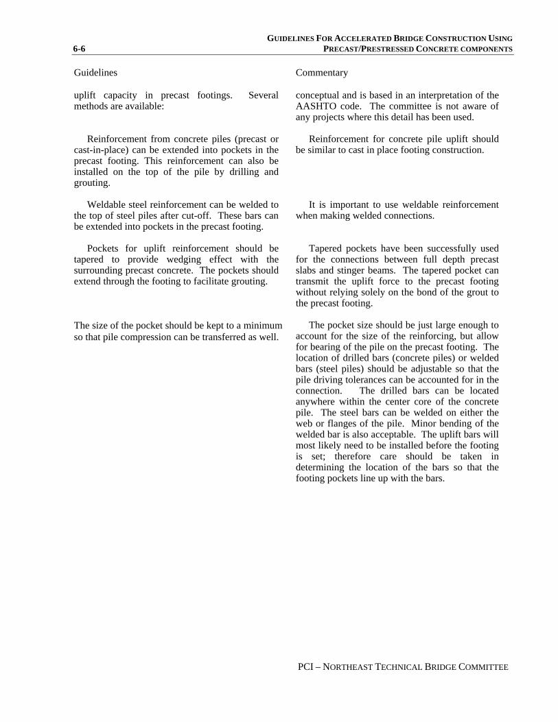
GUIDELINES FOR ACCELERATED BRIDGE CONSTRUCTION USING 6-6 PRECAST/PRESTRESSED CONCRETE COMPONENTS
PCI – NORTHEAST TECHNICAL BRIDGE COMMITTEE
Guidelines
Commentary
uplift capacity in precast footings. Several methods are available:
Reinforcement from concrete piles (precast or
cast-in-place) can be extended into pockets in the precast footing. This reinforcement can also be installed on the top of the pile by drilling and grouting.
Weldable steel reinforcement can be welded to
the top of steel piles after cut-off. These bars can be extended into pockets in the precast footing.
Pockets for uplift reinforcement should be
tapered to provide wedging effect with the surrounding precast concrete. The pockets should extend through the footing to facilitate grouting.
The size of the pocket should be kept to a minimum so that pile compression can be transferred as well.
conceptual and is based in an interpretation of the AASHTO code. The committee is not aware of any projects where this detail has been used.
Reinforcement for concrete pile uplift should
be similar to cast in place footing construction. It is important to use weldable reinforcement
when making welded connections. Tapered pockets have been successfully used
for the connections between full depth precast slabs and stinger beams. The tapered pocket can transmit the uplift force to the precast footing without relying solely on the bond of the grout to the precast footing.
The pocket size should be just large enough to
account for the size of the reinforcing, but allow for bearing of the pile on the precast footing. The location of drilled bars (concrete piles) or welded bars (steel piles) should be adjustable so that the pile driving tolerances can be accounted for in the connection. The drilled bars can be located anywhere within the center core of the concrete pile. The steel bars can be welded on either the web or flanges of the pile. Minor bending of the welded bar is also acceptable. The uplift bars will most likely need to be installed before the footing is set; therefore care should be taken in determining the location of the bars so that the footing pockets line up with the bars.
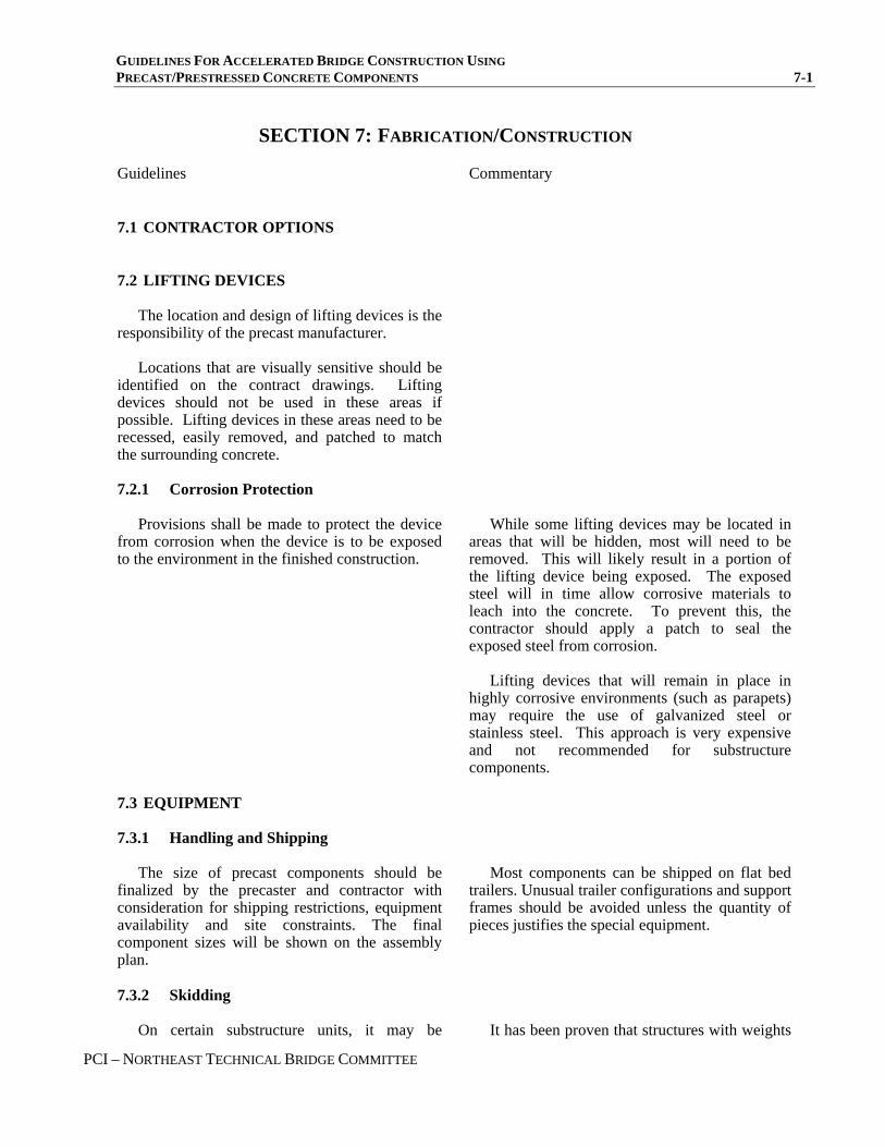
GUIDELINES FOR ACCELERATED BRIDGE CONSTRUCTION USING PRECAST/PRESTRESSED CONCRETE COMPONENTS 7-1
PCI – NORTHEAST TECHNICAL BRIDGE COMMITTEE
SECTION 7: FABRICATION/CONSTRUCTION
Guidelines
Commentary
7.1 CONTRACTOR OPTIONS
7.2 LIFTING DEVICES
The location and design of lifting devices is the responsibility of the precast manufacturer.
Locations that are visually sensitive should be
identified on the contract drawings. Lifting devices should not be used in these areas if possible. Lifting devices in these areas need to be recessed, easily removed, and patched to match the surrounding concrete.
7.2.1 Corrosion Protection
Provisions shall be made to protect the device from corrosion when the device is to be exposed to the environment in the finished construction.
While some lifting devices may be located in
areas that will be hidden, most will need to be removed. This will likely result in a portion of the lifting device being exposed. The exposed steel will in time allow corrosive materials to leach into the concrete. To prevent this, the contractor should apply a patch to seal the exposed steel from corrosion.
Lifting devices that will remain in place in
highly corrosive environments (such as parapets) may require the use of galvanized steel or stainless steel. This approach is very expensive and not recommended for substructure components.
7.3 EQUIPMENT
7.3.1 Handling and Shipping
The size of precast components should be finalized by the precaster and contractor with consideration for shipping restrictions, equipment availability and site constraints. The final component sizes will be shown on the assembly plan.
Most components can be shipped on flat bed
trailers. Unusual trailer configurations and support frames should be avoided unless the quantity of pieces justifies the special equipment.
7.3.2 Skidding
On certain substructure units, it may be
It has been proven that structures with weights

GUIDELINES FOR ACCELERATED BRIDGE CONSTRUCTION USING 7-2 PRECAST/PRESTRESSED CONCRETE COMPONENTS
PCI – NORTHEAST TECHNICAL BRIDGE COMMITTEE
Guidelines
Commentary
desirable to assemble the entire structure or a portion of the structure adjacent to the final installation location and jack it horizontally into its final position. This should only be considered for complex locations where traffic disruption is very limited.
as high as 6 million pounds can be skidded into place using specialized skidding equipment, hydraulic jacks, or cable systems. This is very expensive specialized work; therefore it should only be used in areas where the time of change-out from an old structure to a new structure is very limited.
7.4 ASSEMBLY PLAN
This plan is created by the Precaster and Contractor and submitted to the Owner for approval. It provides detailed information on the Contractor’s means and methods for assembling the components.
The assembly plan should at the very least,
include all information required to complete the work such as:
• Engineer of Record for the assembly plan. • Shop drawings of all components. • Specific product names and other material
requirements for all grout products proposed for use.
• Proposed method of erection and the amount and character of equipment required.
• Temporary support requirements for substructures including leveling screws and/or shims and lateral load and moment resistance requirements for vertical components during assembly.
• Component assembly sequence. • Tolerance requirements for the assembly of
the components. • Grouting plan.
The assembly plan is one piece of a project
delivery concept devised for accelerated bridge construction. This concept allows the Owner to design the structure and gives the contractor the ability to decide the most suitable means to assemble the components.
The contract drawings provide a design and
standard details for joints within the structure and performance requirements for materials that are used to assemble the components.
7.5 COORDINATION
Coordination between all parties is paramount with accelerated construction.
The importance of establishing lines of
communication between all parties involved cannot be overstated. The decision makers in each discipline must be identified early, and they must be available by phone to make timely decisions when things don’t go completely as planned.

GUIDELINES FOR ACCELERATED BRIDGE CONSTRUCTION USING PRECAST/PRESTRESSED CONCRETE COMPONENTS 7-3
PCI – NORTHEAST TECHNICAL BRIDGE COMMITTEE
Guidelines
Commentary
7.6 TOLERANCES
7.6.1 Fabrication
Fabrication tolerances shall be according to standard precast practice. See PCI MNL-116, Manual for Quality Control for Plants and Production of Precast and Prestressed Concrete Products or PCI MNL –135-00 Tolerance Manual for Precast and Prestressed Concrete Construction for more detailed tolerances for precast components. Tolerances for project specific requirements should be detailed in the project specifications.
7.6.2 Vertical Control in the Field
Horizontal joints shall follow appropriate tolerances to ensure final elevations are as specified on the contract plans.
Errors in horizontal joints will accumulate
with each joint. The designer should limit horizontal joints to as few as possible. Horizontal joints should be detailed to allow for minor adjustments as required during construction.
7.6.3 Horizontal Control in the Field
Gaps between adjacent wall components should provide for fabrication and construction tolerances. Contractor should survey and layout location of components prior to installation. Layout control should continue throughout assembly.
Grouted shear keys can be introduced as
required to provide additional fabrication and assembly tolerances if needed.
7.7 INSPECTION
7.7.1 Grouting of Horizontal Post-Tensioning Ducts
The post-tensioning duct grout should be mixed according to the grout manufacturer’s published mixing instructions.
Sufficient grout should be on site to completely
grout an entire unit prior to commencing the mixing of any grout.
In order for the grout to work properly it must
be mixed to the consistency intended by the manufacturer.
Particular attention should be paid to the
published recommended pot life of a mixed batch of grout. Once the process of grouting has begun it must continue without interruption until it is complete, or there is a risk of leaving ungrouted ducts, or portions thereof, in the completed work.

GUIDELINES FOR ACCELERATED BRIDGE CONSTRUCTION USING 7-4 PRECAST/PRESTRESSED CONCRETE COMPONENTS
PCI – NORTHEAST TECHNICAL BRIDGE COMMITTEE
Guidelines
Commentary
Grouting of post-tensioning ducts should be done from one end only.
Grouting should be continuous from one end of the post-tensioning duct, and should be continued until grout flows from the grout port at the opposite end of the duct being grouted.
7.7.2 Mechanical Grouted Splices
A template will be required for accurate mechanical splice placement during component fabrication and/or field cast conditions to ensure component compatibility.
The grouting process should follow the
manufacturer’s published recommendations for materials and equipment.
Templates should be used during fabrication to
ensure fit-up between joined components. Proper dowel extensions are required to develop the full capacity of the grouted mechanical splice. Placement tolerances should be as recommended by the mechanical splice manufacturer.
A minimum of two inspectors should be
required for the mechanical splice grouting operation: one to watch the grout preparation and one to watch the grouting process.
7.8 BACKFILL
The plans and specifications should allow for contractor alternates for backfill materials. The plans should indicate which of the backfill options are acceptable for each substructure unit.
In many cases, there may not be an obvious
solution to the most cost effective backfill material. Contractor alternates will facilitate the most cost effective solutions.
7.8.1 Flowable Fill
This material has the ability to rapidly backfill a structure without the need for compaction. The designer should investigate the effects of the flowable fill on the substructure.
Flowable fill can be installed quickly, however
it has several drawbacks. The actual material is more expensive than granular fill, and the area to be filled will need to be secured with either formwork or embankments. In some cases, the cost of these items may outweigh the cost of compacting traditional granular fill.
Flowable fill will exert significant fluid
pressure on the substructure prior to setting. This loading condition should be checked in the design, if flowable fill is specified.
7.8.2 Compacted Granular Fill
Normal compacted granular fill may be used for backfilling operations.
7.8.3 Foam Products
Foam products can be used to facilitate backfilling operations. These products consist of
Stacking of these blocks can progress very
fast. These blocks are normally supplemented

GUIDELINES FOR ACCELERATED BRIDGE CONSTRUCTION USING PRECAST/PRESTRESSED CONCRETE COMPONENTS 7-5
PCI – NORTHEAST TECHNICAL BRIDGE COMMITTEE
Guidelines
Commentary
lightweight (3 pcf) polystyrene blocks that are stacked behind a substructure unit.
The designer should investigate the effects of
this material on the design of the substructure since the unit weight is much less than traditional granular backfills.
The elevation of the water table should also be
studied since these products can float.
with flowable fill and/or granular backfill. The light unit weight may affect the design of
structures where the dead load of the backfill is used to counteract overturning forces.
There are two issues with these products.
First, the compressive strength of the blocks is limited; therefore a layer of granular material above the blocks will be required in order to distribute the wheel loads to the blocks. Second, the designer should investigate floatation of the blocks in areas where the water table is above the bottom of the blocks. Often the buoyancy can be offset by the weight of the granular fill over the blocks.
Another problem is that polystyrene blocks
tend to be very reactive to petroleum products. In some cases, polystyrene blocks can dissolve rapidly when in contact with petroleum fuels. Caution should be used when installing in locations where fuel is stored.

GUIDELINES FOR ACCELERATED BRIDGE CONSTRUCTION USING 7-6 PRECAST/PRESTRESSED CONCRETE COMPONENTS
PCI – NORTHEAST TECHNICAL BRIDGE COMMITTEE

GUIDELINES FOR ACCELERATED BRIDGE CONSTRUCTION USING PRECAST/PRESTRESSED CONCRETE COMPONENTS 8-1
PCI – NORTHEAST TECHNICAL BRIDGE COMMITTEE
SECTION 8: CASE STUDY 1, UPTON, MAINE
CASE STUDY 1 East B Hill Road in Upton, Maine

GUIDELINES FOR ACCELERATED BRIDGE CONSTRUCTION USING 8-2 PRECAST/PRESTRESSED CONCRETE COMPONENTS
PCI – NORTHEAST TECHNICAL BRIDGE COMMITTEE
INSTANT BRIDGE – JUST ADD WATER
Nathaniel D. Benoit, PE, Maine Department of Transportation, Augusta, ME Eric T. Calderwood, PE, Calderwood Engineering etc, Richmond, ME
Wayne L. Frankhauser, Jr., PE, Maine Department of Transportation, Augusta, ME Dennis R. Hanson, EIT, Technical Construction Inc., Turner, ME
Kenneth R. Heil, PE, Figg Bridge Engineers Inc., Exton, PA Jeffrey J. Tweedie, PE, Maine Department of Transportation, Augusta, ME
ABSTRACT
This report is a case study on a project under taken by the Maine Department of Transportation in 2004. In September of 2004 the Maine Department of Transportation completed construction of the Andover Dam Bridge in Upton, Maine. The design of the bridge consists of a 65-ft single span, precast, butted box beam superstructure, founded on pile-supported, integral abutments. The bridge is located on a local road in rural Maine, and the use of a long detour and rapid bridge construction techniques were determined more cost effective than the use of a temporary bridge. For this project the use of self consolidating concrete combined with a precast concrete substructure and superstructure enabled the bridge to be constructed while the road was closed for a total duration of 96 hours. This case study discusses the background information, specifics of the new construction, traffic considerations, construction sequence, precast components, and lessons learned by the Department during the construction of this project.
Keywords: Rapid Bridge, Precast Substructure, Integral Abutments, Self Consolidated Concrete
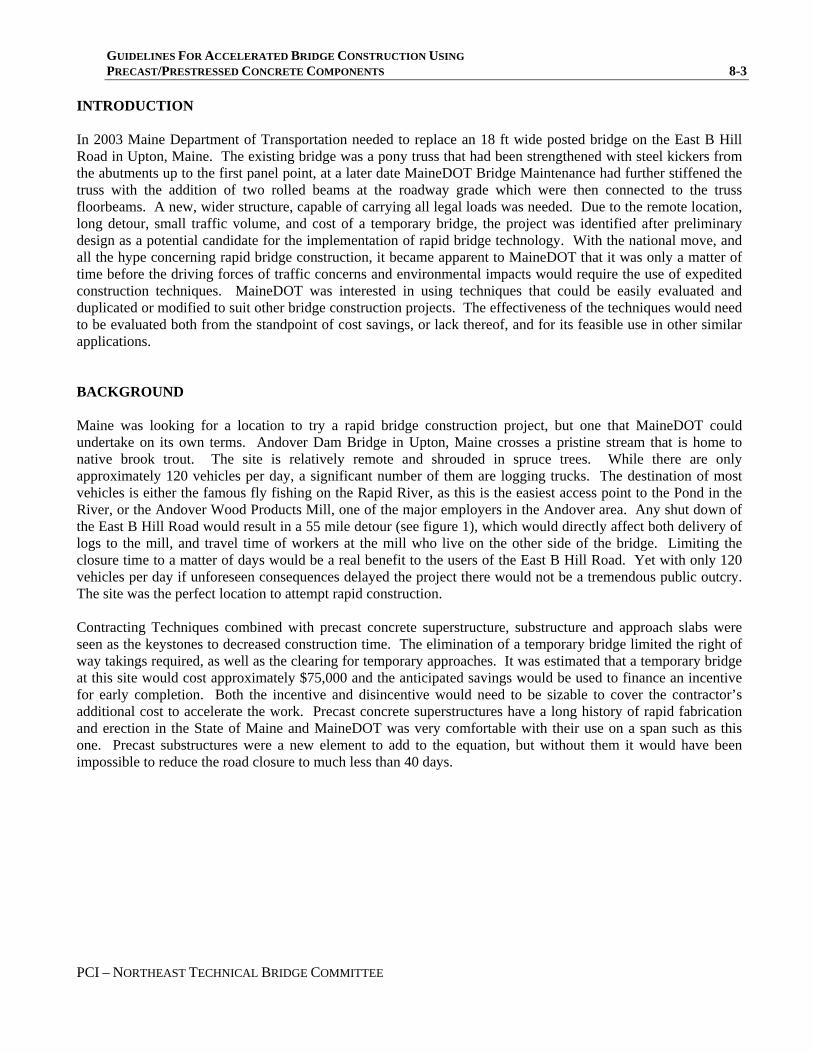
GUIDELINES FOR ACCELERATED BRIDGE CONSTRUCTION USING PRECAST/PRESTRESSED CONCRETE COMPONENTS 8-3
PCI – NORTHEAST TECHNICAL BRIDGE COMMITTEE
INTRODUCTION In 2003 Maine Department of Transportation needed to replace an 18 ft wide posted bridge on the East B Hill Road in Upton, Maine. The existing bridge was a pony truss that had been strengthened with steel kickers from the abutments up to the first panel point, at a later date MaineDOT Bridge Maintenance had further stiffened the truss with the addition of two rolled beams at the roadway grade which were then connected to the truss floorbeams. A new, wider structure, capable of carrying all legal loads was needed. Due to the remote location, long detour, small traffic volume, and cost of a temporary bridge, the project was identified after preliminary design as a potential candidate for the implementation of rapid bridge technology. With the national move, and all the hype concerning rapid bridge construction, it became apparent to MaineDOT that it was only a matter of time before the driving forces of traffic concerns and environmental impacts would require the use of expedited construction techniques. MaineDOT was interested in using techniques that could be easily evaluated and duplicated or modified to suit other bridge construction projects. The effectiveness of the techniques would need to be evaluated both from the standpoint of cost savings, or lack thereof, and for its feasible use in other similar applications. BACKGROUND Maine was looking for a location to try a rapid bridge construction project, but one that MaineDOT could undertake on its own terms. Andover Dam Bridge in Upton, Maine crosses a pristine stream that is home to native brook trout. The site is relatively remote and shrouded in spruce trees. While there are only approximately 120 vehicles per day, a significant number of them are logging trucks. The destination of most vehicles is either the famous fly fishing on the Rapid River, as this is the easiest access point to the Pond in the River, or the Andover Wood Products Mill, one of the major employers in the Andover area. Any shut down of the East B Hill Road would result in a 55 mile detour (see figure 1), which would directly affect both delivery of logs to the mill, and travel time of workers at the mill who live on the other side of the bridge. Limiting the closure time to a matter of days would be a real benefit to the users of the East B Hill Road. Yet with only 120 vehicles per day if unforeseen consequences delayed the project there would not be a tremendous public outcry. The site was the perfect location to attempt rapid construction. Contracting Techniques combined with precast concrete superstructure, substructure and approach slabs were seen as the keystones to decreased construction time. The elimination of a temporary bridge limited the right of way takings required, as well as the clearing for temporary approaches. It was estimated that a temporary bridge at this site would cost approximately $75,000 and the anticipated savings would be used to finance an incentive for early completion. Both the incentive and disincentive would need to be sizable to cover the contractor’s additional cost to accelerate the work. Precast concrete superstructures have a long history of rapid fabrication and erection in the State of Maine and MaineDOT was very comfortable with their use on a span such as this one. Precast substructures were a new element to add to the equation, but without them it would have been impossible to reduce the road closure to much less than 40 days.
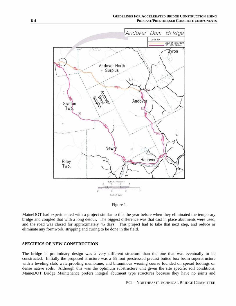
GUIDELINES FOR ACCELERATED BRIDGE CONSTRUCTION USING 8-4 PRECAST/PRESTRESSED CONCRETE COMPONENTS
PCI – NORTHEAST TECHNICAL BRIDGE COMMITTEE
Figure 1
MaineDOT had experimented with a project similar to this the year before when they eliminated the temporary bridge and coupled that with a long detour. The biggest difference was that cast in place abutments were used, and the road was closed for approximately 45 days. This project had to take that next step, and reduce or eliminate any formwork, stripping and curing to be done in the field. SPECIFICS OF NEW CONSTRUCTION The bridge in preliminary design was a very different structure than the one that was eventually to be constructed. Initially the proposed structure was a 65 foot prestressed precast butted box beam superstructure with a leveling slab, waterproofing membrane, and bituminous wearing course founded on spread footings on dense native soils. Although this was the optimum substructure unit given the site specific soil conditions, MaineDOT Bridge Maintenance prefers integral abutment type structures because they have no joints and

GUIDELINES FOR ACCELERATED BRIDGE CONSTRUCTION USING PRECAST/PRESTRESSED CONCRETE COMPONENTS 8-5
PCI – NORTHEAST TECHNICAL BRIDGE COMMITTEE
therefore ease the maintenance of the structure. Because of this preference coupled with site specific scour concerns the decision was made to make the change to integral abutments founded on driven H-Pile. This opened the door to facilitate the implementation of rapid bridge technology. The leveling slab on the box beams was eliminated; the crown of the roadway was introduced in the abutments. The abutments and approach slabs would have to be precast in order to eliminate concrete curing times in the field. The abutments would be in segments to reduce their weight and bond outs would be provided to allow the driven H-Pile to penetrate into the abutment (see figure 2 for abutment configuration). Concrete could then be placed around the piling through fill sleeves to each bond out and the segments would then be post tensioned together. The new abutments were located sufficiently behind the existing abutments such that the piling could be driven behind the abutments, cut off below grade, and the existing abutments could then be backfilled again to carry traffic on the old bridge while new equipment was brought in to erect the superstructure and substructure units (see Figure 4 for construction sequence).
Figure 2
Several factors would determine the geometry of the precast abutment segments. Conceptually the units would be required to:
1. have sufficient post tensioning to carry the passive earth pressure required of integral type abutments 2. be light enough to ship and handle
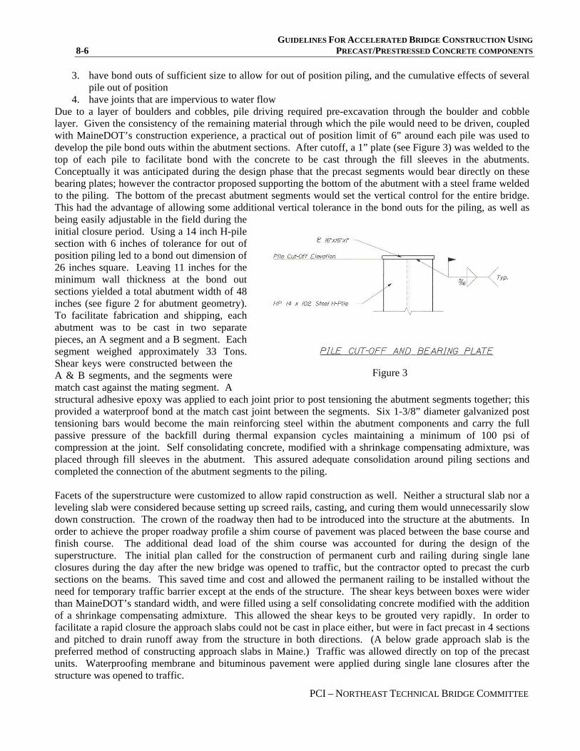
GUIDELINES FOR ACCELERATED BRIDGE CONSTRUCTION USING 8-6 PRECAST/PRESTRESSED CONCRETE COMPONENTS
PCI – NORTHEAST TECHNICAL BRIDGE COMMITTEE
3. have bond outs of sufficient size to allow for out of position piling, and the cumulative effects of several pile out of position
4. have joints that are impervious to water flow Due to a layer of boulders and cobbles, pile driving required pre-excavation through the boulder and cobble layer. Given the consistency of the remaining material through which the pile would need to be driven, coupled with MaineDOT’s construction experience, a practical out of position limit of 6” around each pile was used to develop the pile bond outs within the abutment sections. After cutoff, a 1” plate (see Figure 3) was welded to the top of each pile to facilitate bond with the concrete to be cast through the fill sleeves in the abutments. Conceptually it was anticipated during the design phase that the precast segments would bear directly on these bearing plates; however the contractor proposed supporting the bottom of the abutment with a steel frame welded to the piling. The bottom of the precast abutment segments would set the vertical control for the entire bridge. This had the advantage of allowing some additional vertical tolerance in the bond outs for the piling, as well as being easily adjustable in the field during the initial closure period. Using a 14 inch H-pile section with 6 inches of tolerance for out of position piling led to a bond out dimension of 26 inches square. Leaving 11 inches for the minimum wall thickness at the bond out sections yielded a total abutment width of 48 inches (see figure 2 for abutment geometry). To facilitate fabrication and shipping, each abutment was to be cast in two separate pieces, an A segment and a B segment. Each segment weighed approximately 33 Tons. Shear keys were constructed between the A & B segments, and the segments were match cast against the mating segment. A structural adhesive epoxy was applied to each joint prior to post tensioning the abutment segments together; this provided a waterproof bond at the match cast joint between the segments. Six 1-3/8” diameter galvanized post tensioning bars would become the main reinforcing steel within the abutment components and carry the full passive pressure of the backfill during thermal expansion cycles maintaining a minimum of 100 psi of compression at the joint. Self consolidating concrete, modified with a shrinkage compensating admixture, was placed through fill sleeves in the abutment. This assured adequate consolidation around piling sections and completed the connection of the abutment segments to the piling.
Figure 3
Facets of the superstructure were customized to allow rapid construction as well. Neither a structural slab nor a leveling slab were considered because setting up screed rails, casting, and curing them would unnecessarily slow down construction. The crown of the roadway then had to be introduced into the structure at the abutments. In order to achieve the proper roadway profile a shim course of pavement was placed between the base course and finish course. The additional dead load of the shim course was accounted for during the design of the superstructure. The initial plan called for the construction of permanent curb and railing during single lane closures during the day after the new bridge was opened to traffic, but the contractor opted to precast the curb sections on the beams. This saved time and cost and allowed the permanent railing to be installed without the need for temporary traffic barrier except at the ends of the structure. The shear keys between boxes were wider than MaineDOT’s standard width, and were filled using a self consolidating concrete modified with the addition of a shrinkage compensating admixture. This allowed the shear keys to be grouted very rapidly. In order to facilitate a rapid closure the approach slabs could not be cast in place either, but were in fact precast in 4 sections and pitched to drain runoff away from the structure in both directions. (A below grade approach slab is the preferred method of constructing approach slabs in Maine.) Traffic was allowed directly on top of the precast units. Waterproofing membrane and bituminous pavement were applied during single lane closures after the structure was opened to traffic.

GUIDELINES FOR ACCELERATED BRIDGE CONSTRUCTION USING PRECAST/PRESTRESSED CONCRETE COMPONENTS 8-7
PCI – NORTHEAST TECHNICAL BRIDGE COMMITTEE
CONSTRUCTION SEQUENCE The contractor was given 192 hours of total allowable closure time. The number of closures and duration of each were left to the contractor to decide. In order to ensure the closure was limited to the minimum time required an incentive of $200.00 per hour was offered if the closure took less than 192 hours. An additional incentive of $10,000 was provided for simply meeting the 192 hour deadline. The incentives were combined with a graduated disincentive beginning at $300.00 per hour and ending at $600.00 per hour for each hour the road was closed in excess of the allowable 192 hours. In order to be effective the incentive and disincentive had to be by the hour, if we had used a per day rate it would be easy to use the whole day once a part of it had been used, but using a per hour rate made it even more imperative to make the road opening requirements very clear to the contractor. THREE INITIAL CLOSURE PERIODS The first closure period was used to remove obstructions to pile driving and install the driven H-pile at abutment #1. The pre-excavation was required to be moderately deeper than shown on the plans, and although we came close to the water table, we were not required to drastically modify the construction procedure with the addition of a separate cofferdam, pumps and sedimentation basins. Once the pile driving was complete the driving frame was welded to the driven pile at exactly the proposed elevation of the bottom of the abutments. This would serve to support the abutment segments during the final closure. Careful measurements to each pile were taken from the centerline of construction. These would be used during fabrication of the abutments to verify the locations of the bond outs in the precast units. The elevation to remove the existing abutment to was carefully located on the abutment face. This would be used later to perforate the abutment facilitating easy removal during the final closure. The installation of piling went over without incident, and the native soils were placed back into the hole and compacted adequately to open the road to traffic. The total road closure period for the first closure period was 12 hours.
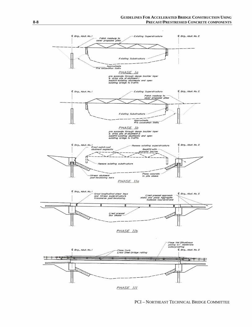
GUIDELINES FOR ACCELERATED BRIDGE CONSTRUCTION USING 8-8 PRECAST/PRESTRESSED CONCRETE COMPONENTS
PCI – NORTHEAST TECHNICAL BRIDGE COMMITTEE

GUIDELINES FOR ACCELERATED BRIDGE CONSTRUCTION USING PRECAST/PRESTRESSED CONCRETE COMPONENTS 8-9
PCI – NORTHEAST TECHNICAL BRIDGE COMMITTEE
Figure 4 The second closure period was used to remove obstructions to pile driving and install the driven H-pile at abutment number two. Although, after the initial closure’s success, spirits were high it became apparent early on that we would not be quite so fortunate on the second day. Once the hole was opened up and we excavated below the existing road gravel, the excavator began to take out buckets full of nothing but rock, we had found the remains of the bridges namesake, the Andover Dam. Nonetheless we were fortunate not to find any log crib below the stone, or what our biggest fear was, below the existing abutment. Once we had excavated through the obstruction layer we found that the existing abutment had a heel that projected into and interfered with the pile driving locations. The contractor had to get a Hoe Ram on site. At this point it was clear that we would not be driving pile today. The pile driving subcontractor had serious, well founded, safety concerns regarding driving pile after dark, and we would therefore have to fill the excavation with material through which we could drive the pile up to the bottom of the new abutment location. The remainder of the hole was filled in with native soils and compacted sufficiently to open the road to traffic. The total road closure period for the second closure was 12 hours. The third closure period was used to complete the preparatory work at abutment number two. The existing abutment had been marked during the previous closure to indicate when we could stop digging. The pile driving frame was installed and the piles were driven to the required resistance, although one of the pile encountered an obstruction causing it to deviate significantly from its theoretical position, it was pulled and restarted several times with the same results. Finally, although not exactly in the right position the last pile was driven. Careful measurements were taken to the actual piling locations. The frame was then erected and welded to the piling at the exact elevation required for the bottom of the abutments. Native materials were used to backfill the existing abutment and the road was opened to traffic. The total road closure period for the third closure was 12 hours. SIX WEEKS OF PREPARATION During the 6 weeks following these initial closure periods, preparations were being made to facilitate an expedited schedule during the last closure period. The existing abutments were perforated with two inch diameter holes at a two foot spacing located at the required cutoff elevation. While this did not impact the structural capacity of the existing bridge it facilitated easy removal during the fourth and final closure. Granular backfill and riprap were stockpiled just off site. Coordination between the contractor and his subs and suppliers was critical. Everything had to come together at the same time. The Abutments were under fabrication. No modifications were required at the bond out locations for abutment #1; abutment #2 was moderately modified to better reflect the actual location of the driven H-pile. The pile that had encountered an obstruction that altered its final location was out of position by exactly the six inch tolerance that we had allowed for in the bond outs. While theoretically it would be possible to erect the segments if they were constructed as designed, we decided to shift the bond out for that piling sufficiently to allow the greatest flexibility in the field. Once all the preparations were made, materials stockpiled, concrete trial batched, precast concrete boxes and abutments were all fabricated and were either delivered or on the road. The stage was set for the fourth and final closure. THE FINAL CLOSURE PERIOD The first day of the final closure period was full of activity. Work was taking place on both sides of the river simultaneously. One large excavator worked at removing the soil down to the driving frame, carefully uncovering it to reveal the support for the abutment segments at abutment #1. Simultaneously, a second excavator removed the grade beams and concrete deck from the truss. A hydraulic crane set up to place the abutment segments at abutment #1. At this point it was critical that the segments be erected at abutment #1 early

GUIDELINES FOR ACCELERATED BRIDGE CONSTRUCTION USING 8-10 PRECAST/PRESTRESSED CONCRETE COMPONENTS
PCI – NORTHEAST TECHNICAL BRIDGE COMMITTEE
in the day to allow the crane time to break down and travel all the way around the detour in order to be prepared to set the abutment segments at abutment #2. The abutment segments were erected very smoothly, and post tensioning began immediately. Once the post tensioning was complete, backfill was placed carefully on both sides of the abutment keeping the elevation approximately the same so as not to shift its alignment at all. The existing truss was removed and the old abutments were removed to their final elevations, 1 foot below the finished slope line. Riprap was placed in areas that would be located underneath the new superstructure. Self consolidating concrete was placed through the fill sleeves to permanently connect the abutment to its foundation piling. The first day was complete after about 14 hours of the final closure period. The second day of the final closure was similarly exciting. Abutment #2 segments were placed and post tensioned. Abutment #2 was backfilled, and self consolidating concrete filled the pile bond outs. Rip rap was placed in front of abutment #2. The precast box beams were erected, and the hydraulic crane was broken down and sent home. The second day of the final closure period was complete after about 38 hours of the final closure period. The third and final day of the final closure cleaned up most of the details. The approach slabs were set at the appropriate grade, the precast box beam superstructure was anchored into the abutments, lateral post tensioning strands between box beams were installed, and the shear keys between the box beams were filled with self consolidating concrete. Bond outs in the curb were filled with the same concrete mix. Bridge rail was installed, gravel was placed and the approaches were graded, and the structure was opened to traffic. The final closure period lasted a total of 60 hours. The total elapsed road closure time for the bridge replacement was only 96 hours. FINAL COMPLETION Several elements were then completed under traffic with only single lane closures. This included grouting the post tensioning tendons within the abutments, installing waterproof membrane and bituminous pavement, grouting the post tensioning pockets. Completing the approach work also was done under traffic. LESSONS LEARNED MaineDOT learned several lessons during the construction of the Upton Andover Dam Bridge. Operations taking place simultaneously tend to be extremely equipment intensive, and there is a tremendous amount of real estate required for lay down areas, storage, and equipment in order to keep multiple operations going simultaneously. Plan on separate closures for pile driving and make sure there is plenty of room behind the existing abutments to avoid piling and the bottom of a battered mass concrete abutment sharing the same physical space. Take more borings than you think you need, because once the road is closed you are committed. Keep the details simple and clean, nothing fancy. Don’t pin the box beams to the abutments, pin the approach slabs instead. Don’t be tempted to reduce the incentive, or to cut the allowable closure time significantly, because it must be possible for the contractor to achieve a bonus significant enough to account for the additional expenses of accelerating the work. CONCLUSIONS The experimental rapid bridge in Upton, Maine was a very successful project and will lead to the use of similar techniques on other bridge replacement projects where a reduction in traffic disruption is beneficial. MaineDOT was initially concerned that even though we would be eliminating a temporary bridge with significant cost

GUIDELINES FOR ACCELERATED BRIDGE CONSTRUCTION USING PRECAST/PRESTRESSED CONCRETE COMPONENTS 8-11
PCI – NORTHEAST TECHNICAL BRIDGE COMMITTEE
associated with it, the accelerated schedule, incentive, and precast substructure would drive the cost above that of a more conventionally constructed bridge. That concern proved to be unfounded, and although it is difficult to say for certain, it’s generally agreed within the Department that the project resulted in a cost savings. Part of the reason for this may lie in the equipment intensive operations which lend themselves well to rental equipment. Additionally, when the construction duration is limited, the contractor has less overhead cost associated with the project. The environmental benefits seem to be very promising. The area which would have been cleared and used for temporary approaches to a temporary bridge could remain wooded. Areas that were destabilized by excavating for the new abutments were completely stabilized with the final rip rap placement the same day. The excavation only stayed open for a matter of hours. While vehicular travel time was significantly impacted during the closure periods, people had sufficient advanced warning and could plan their schedules accordingly. They did not seem to mind the bridge closing for a few days. MaineDOT has realized that rapid bridge construction can save the state money and limit inconvenience for the traveling public. In a state where much of the economy is dependent on tourism it is sometimes beneficial to shift the disruption caused by construction to a period more acceptable to the local business community. MaineDOT has already put these same techniques to work on two other projects which are under construction during the writing of this paper. Both of these projects have more significant traffic volumes and are in more prominent locations. Although this is not going to become the standard construction methodology in the state, it is going to be another tool that the bridge designer can have in his toolbox to be applied in the right circumstances to save money, traffic disruption, and environmental impacts.

GUIDELINES FOR ACCELERATED BRIDGE CONSTRUCTION USING 8-12 PRECAST/PRESTRESSED CONCRETE COMPONENTS
PCI – NORTHEAST TECHNICAL BRIDGE COMMITTEE
GUIDELINES FOR ACCELERATED BRIDGE CONSTRUCTION USING PRECAST/PRESTRESSED CONCRETE COMPONENTS 9-1
PCI – NORTHEAST TECHNICAL BRIDGE COMMITTEE
SECTION 9: CASE STUDY 2, BROOKSVILLE, MAINE
CASE STUDY 2 Davis Narrows Bridge in Brooksville, Maine

GUIDELINES FOR ACCELERATED BRIDGE CONSTRUCTION USING 9-2 PRECAST/PRESTRESSED CONCRETE COMPONENTS
PCI – NORTHEAST TECHNICAL BRIDGE COMMITTEE
Davis Narrows Bridge in Brooksville, Maine: Fast Track Solution to and Environmentally Sensitive and Tourist Location
M. Asif Iqbal, P.E.
Maine Department of Transportation
Augusta, Maine
ABSTRACT
The unique features of the existing Bridge, the sensitive environmental habitat, and the tourist attraction
at the Davis Narrows Bridge over the Bagaduce River in Brooksville, Maine created a set of issues that
demanded a fast track approach to bridge design and construction. The Maine Department of
Transportation after considering several options decided to custom design a single span bridge using all
precast elements. The Precast abutments and wingwalls were designed as post-tensioned units over
driven piles to reduce excavation, forming and curing time, and to eliminate the use of cofferdams.
Extensive geotextiles were used to stabilize the causeways and reduce impacts to Eelgrass patches.
The new abutments were installed behind the existing granite block abutments to avoid changes to
hydraulics favored by locals and tourists. Precast Box-beams were erected efficiently using a launching
girder. The entire project from demolition of the existing bridge to pavement and guardrail installation on
the new 89 foot, $1 million Bridge was completed in only 30 days. The ease with which the bridge was
constructed not only impressed the locals but also the Contractor and the Owner.
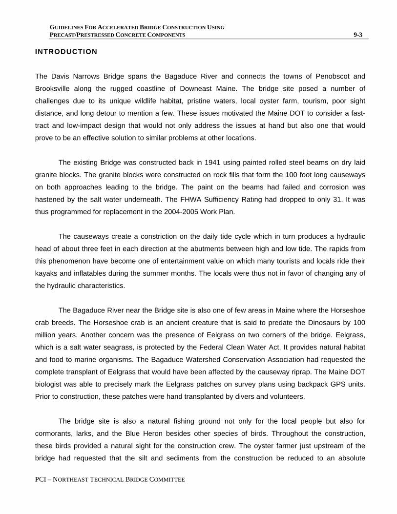
GUIDELINES FOR ACCELERATED BRIDGE CONSTRUCTION USING PRECAST/PRESTRESSED CONCRETE COMPONENTS 9-3
PCI – NORTHEAST TECHNICAL BRIDGE COMMITTEE
INTRODUCTION
The Davis Narrows Bridge spans the Bagaduce River and connects the towns of Penobscot and
Brooksville along the rugged coastline of Downeast Maine. The bridge site posed a number of
challenges due to its unique wildlife habitat, pristine waters, local oyster farm, tourism, poor sight
distance, and long detour to mention a few. These issues motivated the Maine DOT to consider a fast-
tract and low-impact design that would not only address the issues at hand but also one that would
prove to be an effective solution to similar problems at other locations.
The existing Bridge was constructed back in 1941 using painted rolled steel beams on dry laid
granite blocks. The granite blocks were constructed on rock fills that form the 100 foot long causeways
on both approaches leading to the bridge. The paint on the beams had failed and corrosion was
hastened by the salt water underneath. The FHWA Sufficiency Rating had dropped to only 31. It was
thus programmed for replacement in the 2004-2005 Work Plan.
The causeways create a constriction on the daily tide cycle which in turn produces a hydraulic
head of about three feet in each direction at the abutments between high and low tide. The rapids from
this phenomenon have become one of entertainment value on which many tourists and locals ride their
kayaks and inflatables during the summer months. The locals were thus not in favor of changing any of
the hydraulic characteristics.
The Bagaduce River near the Bridge site is also one of few areas in Maine where the Horseshoe
crab breeds. The Horseshoe crab is an ancient creature that is said to predate the Dinosaurs by 100
million years. Another concern was the presence of Eelgrass on two corners of the bridge. Eelgrass,
which is a salt water seagrass, is protected by the Federal Clean Water Act. It provides natural habitat
and food to marine organisms. The Bagaduce Watershed Conservation Association had requested the
complete transplant of Eelgrass that would have been affected by the causeway riprap. The Maine DOT
biologist was able to precisely mark the Eelgrass patches on survey plans using backpack GPS units.
Prior to construction, these patches were hand transplanted by divers and volunteers.
The bridge site is also a natural fishing ground not only for the local people but also for
cormorants, larks, and the Blue Heron besides other species of birds. Throughout the construction,
these birds provided a natural sight for the construction crew. The oyster farmer just upstream of the
bridge had requested that the silt and sediments from the construction be reduced to an absolute

GUIDELINES FOR ACCELERATED BRIDGE CONSTRUCTION USING 9-4 PRECAST/PRESTRESSED CONCRETE COMPONENTS
PCI – NORTHEAST TECHNICAL BRIDGE COMMITTEE
minimum. This was achieved by using precast abutments instead of cast-in-place which significantly
reduced equipment movement, excavation, and flow of any concrete into the tidal area. Use of precast
units for abutments also eliminated the need for cofferdams which would have disturbed the river
sediments. The use of silt booms at both abutments was all that was needed with the precast system.
Given the sensitive nature of the project surroundings, the design team considered the options
available and decided on an all-precast system to quickly install the bridge, address the issues at the
site, and open the road to traffic in the shortest time possible.
BRIDGE DESIGN AND CONSTRUCTION
The bridge was designed by the Maine DOT Bridge Program design team during the winter of 2004-
2005 according to AASHTO LRFD Bridge Design Specifications. Some of the precast features were
conceived from the Andover Dam Bridge in Upton which is the only other bridge in the state with precast
abutments. The new bridge is single span, 89 feet long and 32 feet wide with integral abutments. The
design theory for the precast abutment was based on using conventional integral-abutment dimensions
and then splitting the abutment into segments that can be easily transported and erected. Since the
abutment units are supported on piles, the entire abutment needed to act as a single unit which was
accomplished by post-tensioning the units with threaded bars. The project was advertised in May of
2005 and awarded to Reed and Reed Inc. contractors of Woolwich, Maine in July, 2005 for a total bid
price of $1.06 million. All precast abutment units and box beams were manufactured by Strescon Ltd. of
New Brunswick, Canada. The construction was expected to be quite challenging because the work
schedule needed to be synchronized with the daily tide cycles. The Maine DOT principal designer also
spent the entire 30 days of bridge closure at the construction site to help address issues as they came
up. The project was completed 5 days ahead of the allotted 35 day closure. The details of the
construction process are given below.
Abutments and Wingwalls
Since the hydraulics of the bridge could not be changed, the existing granite block abutments
could not be removed entirely. As a result the new integral abutments were designed twelve feet behind
the existing abutments (See Figure 1-3). It would have been nearly impossible to drive conventional

GUIDELINES FOR ACCELERATED BRIDGE CONSTRUCTION USING PRECAST/PRESTRESSED CONCRETE COMPONENTS 9-5
PCI – NORTHEAST TECHNICAL BRIDGE COMMITTEE
steel sheet-pile cofferdams because of the rocky river-bottom and the long causeway that allowed
significant flow of water through them. As a result, the excavation for the abutments was done within
controlled embankments and at low tide. Silt booms were used on the outside to reduce seepage of silt
and sediments. The dimensions of the precast and post-tensioned abutment units are similar to that of
conventional cast in place integral abutments in Maine.
The integral abutments of the bridge are supported on four piles which are driven to bedrock
(See Figures 2, 5). Light I-beams were placed transversely on each side of the piles to ensure that the
abutments were seated level. The HP 14x89 piles were one size heavier than required to account for
some section loss due to salt water conditions. The piles are expected to be wet at all times. The
abutments consist of two 16 foot long precast center units and two 4 foot long precast extended wing
wall units. All contact surfaces were specified to be match cast at the precasting plant and coated with
epoxy concrete adhesive just prior to post-tensioning in the field. All four units are post-tensioned (PT)
together with six threaded bars. The PT bars were designed to resist biaxial loads on the center units
from traffic and earth pressure, and cantilever loads on the wingwalls due to earth pressure. The match
cast joints also consisted of four shear keys to help align the precast units during erection. Voids were
designed into the abutment units to receive the piles. These voided areas were enlarged to reduce the
shipping weight of the precast units. Once the abutments were lifted into place and the post-tensioning
was completed, the voids were filled with Self Consolidating Concrete (SCC) through six inch ducts on
top of the abutment units. The six PT ducts were pumped with conventional grout. The final lock off
tension in the PT bars was designed to prevent any cracks due to Service Loads. Although the PT bars
provided bending resistance, the steel reinforcement in each unit was designed for deep beam bending
action, and punching shear resistance over the voided areas. All steel reinforcement in the abutment
units were epoxy coated.
Only the small tapering top portions of the wingwalls that abut the box beams were cast in place.
This was necessary to obtain a tight fit of the beams against the abutments. The use of precast
abutments significantly reduced impact to the river and tidal areas, and reduced the construction time by
a third.
Superstructure and Approach Slabs
The superstructure is made of eight butted Precast Pre-stressed Box Beams (B-II 48) that were

GUIDELINES FOR ACCELERATED BRIDGE CONSTRUCTION USING 9-6 PRECAST/PRESTRESSED CONCRETE COMPONENTS
PCI – NORTHEAST TECHNICAL BRIDGE COMMITTEE
post-tensioned transversely to act as a single unit (See Figure 4). They were delivered three per day
which was also the beam erection rate. A 110 ton and an 80 ton crane erected the beams in place. The
contractors were very innovative in their approach to erecting the box beams. The heavy beams would
have required widening the causeways with temporary fills to swing the beams into place and thereby
causing significant impact to the natural habitats. This was eliminated by the use of custom made steel
launching beam with a trolley supported on Hilman rollers. The contractors used the truck that brought
the beams to back-up the beams across the channel thereby eliminating the need to lift an entire beam
off the truck with one crane. The use of pea stone concrete mix in the shear keys instead of the
conventional sand grout reduced the possibility of discharging material into the river. As an additional
measure, the foam backer rods in the shear keys were bonded to the beams prior to erection and then
compressed into place during erection of adjacent beams.
Transverse post-tensioning strands were located at five points along the length of the beam.
Although the designers intended the curbs to be precast with the beams, it was determined that cracks
would have developed during transportation through the rough local roads. Thus the curbs were cast in
place, and this operation started as soon as only two beams were erected. The precast approach slabs
were erected next and these were positively connected to the abutments using six #6 loops providing
longitudinal restraint to the beams. The loops were placed through pockets in the approach slabs and
into precast holes in the abutment units. The pockets were later filled with sand grout. All steel
reinforcements except for the pre-stressing strands were epoxy coated.
The use of precast pre-stressed butted box beams significantly reduced erection time.
Substantial time was also saved by not having to construct a leveling slab. High Performance Membrane
was torch-applied on the beams by a subcontractor followed by a three inch Hot Mix Asphalt pavement.
PROJECT SCHEDULE AND COST The contractors were given a total of thirty five days of road closure to complete the project with
incentives of $1000 per day and equal disincentives. They decided to work on causeways leading to the
bridge first and then close the bridge for completing the rest of the project. The causeways were built
back in 1941 with massive rocks and boulders that allowed significant flow of water through them. To
reduce impact to existing flow characteristics, the new approach roads on the causeways were built on
choke stone layers stabilized with high-flow geotextiles. This took three weeks to complete followed by

GUIDELINES FOR ACCELERATED BRIDGE CONSTRUCTION USING PRECAST/PRESTRESSED CONCRETE COMPONENTS 9-7
PCI – NORTHEAST TECHNICAL BRIDGE COMMITTEE
the bridge closure on September 6th, 2005.
The first week of closure was used to remove the tops of the existing abutments followed by
excavation at the new abutment locations. The second week was used for driving the piles and erecting
the abutments. Some time was lost when two of the pile locations were blocked by large boulders in the
excavation. The contractors did not claim addition time because the presence of boulders was clearly
indicated in the boring logs. The contractors brought in a larger excavator to removes the large boulders.
The four precast units that make up an abutment took only two hours to erect and post-tension. The
grouting operation was done the following day at low tide. During the third week, the beams were
erected using a steel launching beam structure and a crane on either end. The curbs were constructed
as soon as the first fascia beam and an adjacent beam were in place. The wingwall tops were cast early
fourth week followed by installation of bridge rail and application of the high performance membrane.
The heavy cranes were also disassembled during this week and removed from site. Pavement was
applied during the last two days leading to bridge opening. The bridge was opened to traffic on October
5th, 2005. The approach guardrails were installed during the two days following the bridge opening and
no lane closures were needed due to the low traffic volume at that time. The contractors also left the site
four days after the bridge was opened to traffic.
The Davis Narrows Bridge was constructed on a very unique site which posed some significant
construction challenges. The structure itself is one of a kind and as such the cost of this bridge cannot
be easily compared to other bridges in Maine. The unit cost of the structure itself was $233 per square
foot. The price of the Box beams were 56% higher than the estimated price and this was attributed to
the high demand for Box beams during that particular time, besides the temporary shortage of cement.
The increased cost of transportation was also a factor. The bid price of the precast abutments per cubic
yard of concrete was 80% higher than conventional cast in place concrete.
CONCLUSION
Overall, the precast systems were fabricated as designed and erected efficiently as expected.
The contractors were very pleased with the swiftness with which they could handle the precast units and
also the ease of installation. At final inspection and finalizing submittals, the contractor and Maine DOT
gave each other high marks for job satisfaction. This was truly a project which had many challenges but
finally came together with the help of dedicated teams from both the Maine DOT and the contractors,
and certainly with the technology of precast units. The success of this project and that of the Andover

GUIDELINES FOR ACCELERATED BRIDGE CONSTRUCTION USING 9-8 PRECAST/PRESTRESSED CONCRETE COMPONENTS
PCI – NORTHEAST TECHNICAL BRIDGE COMMITTEE
Dam Bridge has motivated other designers at Maine DOT to consider similar All-Precast solution on
their projects.

GUIDELINES FOR ACCELERATED BRIDGE CONSTRUCTION USING PRECAST/PRESTRESSED CONCRETE COMPONENTS 9-9
PCI – NORTHEAST TECHNICAL BRIDGE COMMITTEE
Figure 1: Precast Abutment Section showing void and PT bar locations.

GUIDELINES FOR ACCELERATED BRIDGE CONSTRUCTION USING 9-10 PRECAST/PRESTRESSED CONCRETE COMPONENTS
PCI – NORTHEAST TECHNICAL BRIDGE COMMITTEE
Figure 2: Precast Abutment dimensions.

GUIDELINES FOR ACCELERATED BRIDGE CONSTRUCTION USING PRECAST/PRESTRESSED CONCRETE COMPONENTS 9-11
Figure 3: Embankment details showing new and existing abutment.

GUIDELINES FOR ACCELERATED BRIDGE CONSTRUCTION USING 9-12 PRECAST/PRESTRESSED CONCRETE COMPONENTS
PCI – NORTHEAST TECHNICAL BRIDGE COMMITTEE
Figure 4: Typical Superstructure Cross-Section.
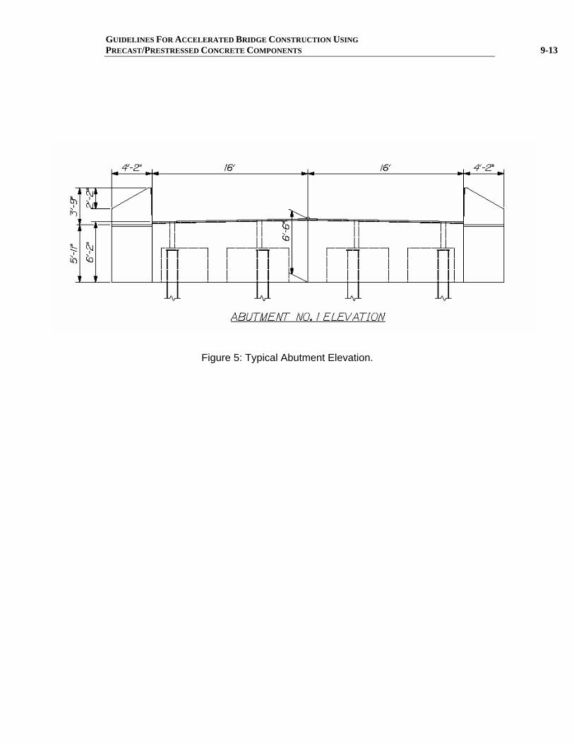
GUIDELINES FOR ACCELERATED BRIDGE CONSTRUCTION USING PRECAST/PRESTRESSED CONCRETE COMPONENTS 9-13
Figure 5: Typical Abutment Elevation.
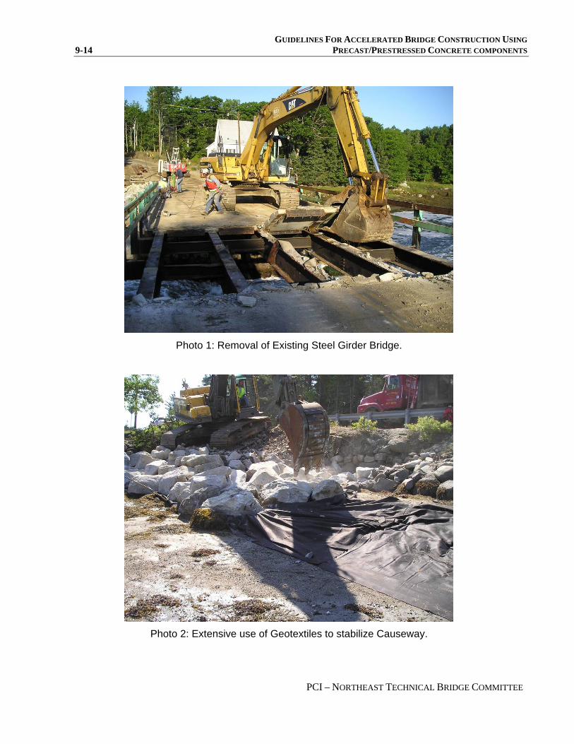
GUIDELINES FOR ACCELERATED BRIDGE CONSTRUCTION USING 9-14 PRECAST/PRESTRESSED CONCRETE COMPONENTS
PCI – NORTHEAST TECHNICAL BRIDGE COMMITTEE
Photo 1: Removal of Existing Steel Girder Bridge.
Photo 2: Extensive use of Geotextiles to stabilize Causeway.

GUIDELINES FOR ACCELERATED BRIDGE CONSTRUCTION USING PRECAST/PRESTRESSED CONCRETE COMPONENTS 9-15
Photo 3: Placement of Center Precast Abutment units.
Photo 4: Precast Abutment voids being aligned with Pile tips.

GUIDELINES FOR ACCELERATED BRIDGE CONSTRUCTION USING 9-16 PRECAST/PRESTRESSED CONCRETE COMPONENTS
PCI – NORTHEAST TECHNICAL BRIDGE COMMITTEE
Photo 5: Self-Consolidating Concrete poured into the voids.
Photo 6: All four Precast Abutment units in place

GUIDELINES FOR ACCELERATED BRIDGE CONSTRUCTION USING PRECAST/PRESTRESSED CONCRETE COMPONENTS 9-17
Photo 7: Launching Beam and first Precast Box beam in place.
Photo 8: Completed Bridge showing causeways.

GUIDELINES FOR ACCELERATED BRIDGE CONSTRUCTION USING 9-18 PRECAST/PRESTRESSED CONCRETE COMPONENTS
PCI – NORTHEAST TECHNICAL BRIDGE COMMITTEE
Photo 9: Completed Bridge photo taken 9 months after completion.

GUIDELINES FOR ACCELERATED BRIDGE CONSTRUCTION USING PRECAST/PRESTRESSED CONCRETE COMPONENTS R-1
SECTION 10: CASE STUDY 3, MILL STREET BRIDGE, EPPING, NEW HAMPSHIRE
CASE STUDY 3 Mill Street Bridge
Epping, New Hampshire PCI Journal Article JR-449
Article Download: http://www.pci.org/pdf/publications/journal/2005/may-june/jl-05-may-june-4.pdf
GUIDELINES FOR ACCELERATED BRIDGE CONSTRUCTION USING R-2 PRECAST/PRESTRESSED CONCRETE COMPONENTS
PCI – NORTHEAST TECHNICAL BRIDGE COMMITTEE
References and Resources
AASHTO LRFD Bridge Design Specifications, 3rd Edition with 2006 Interim Revisions, American Association of State Highway and Transportation Officials. AASHTO Standard Specifications for Highway Bridges, 17th Edition, American Association of State Highway and Transportation Officials. PCI, Manual for Quality Control for Plants and Production of Precast and Prestressed Concrete Products PCI MNL-116. Precast/Prestressed Concrete Institute, Chicago, IL. PCI. 2000. Tolerance Manual for Precast and Prestressed Concrete Construction, First Edition, MNL 135-00. Precast/Prestressed Concrete Institute, Chicago, IL. PCI. 1997. Bridge Design Manual PCI MNL-133-97. Precast/Prestressed Concrete Institute, Chicago, IL. ACI, 2001. Emulating Cast-in-Place Detailing in Precast Concrete Structure ACI 550.1R-01, American Concrete Institute, Farmington Hills, MI ASBI, Construction Practice Handbook For Segmental Concrete Bridges, American Segmental Bridge Institute FHWA, Decision-Making Framework for Prefabricated Bridge Elements and Systems (PBES), May 2006, Federal Highway Administration, Washington, D.C. Design Guidelines (available at www.pcine.org) New England Bulb Tee (NEBT) Post-Tensioned Design Guidelines (June 2001) This report covers design, detailing and construction specifications for post-tensioning and splicing of the New England Bulb Tee (NEBT) girder. Splicing of the girders allows for longer span lengths and the elimination of intermediate bridge piers. Post-tensioning can be used to make bridges continuous. If a State standard exists it will take precedence over these guidelines & details. Load Charts for New England Bulb Tee - LRFD Load Charts (1998) Preliminary Design charts for designing the New England Bulb Tee Girders. Charts will help you determine span capabilities, spacing and preliminary number of prestressing strands required. If a State Standard exists it will take precedence over these guidelines and details. Load Charts for New England Bulb Tee - HS25 Load Charts (1998) Preliminary Design charts for designing the New England Bulb Tee Girders. Charts will help you determine span capabilities, spacing and preliminary number of prestressing strands required. If a State Standard exists it will take precedence over these guidelines and details. Load Charts for New England Bulb Tee - HS20 Load Charts (1998) Preliminary Design charts for designing the New England Bulb Tee Girders. Charts will help you determine span capabilities, spacing and preliminary number of prestressing strands required. If a State Standard exists it will take precedence over these guidelines and details. Load Charts for New England Bulb Tee - Instructions for Use and Section Properties (1998) Preliminary Design charts for designing the New England Bulb Tee Girders. Charts will help you determine span capabilities, spacing and preliminary number of prestressing strands required. If a State Standard exists it will take precedence over these guidelines and details.

GUIDELINES FOR ACCELERATED BRIDGE CONSTRUCTION USING PRECAST/PRESTRESSED CONCRETE COMPONENTS R-3
Full Depth Precast Concrete Deck Slabs (June 2002) Design Guidelines for the use of Full Depth Precast Deck Slabs used for new construction or for replacement of existing decks on bridges. This guideline has been reviewed and approved by the New England Technical committee. Several projects have already used these details and specification. If a State Standard exists it will take precedence. High Performance Concrete for Prestressed Concrete Bridges (September 2001) Guide specification for High Performance Concrete developed by New Hampshire DOT. New Hampshire is the lead state under the Federal Highway demonstration project for HPC in our region. This guideline has been reviewed and approved by the New England Technical committee. Several projects have already used this specification. If a State Standard exists it will take precedence. Bridge Member Repair Guidelines (January 2003) This report is intended to serve as a guide to identify defects that may occur during the fabrication of bridge elements. The report gives guidance on possible cause and prevention. It will help determine the consequences of the defects and assist in making a judgment as to acceptance/repair or rejection. This report can be utilized by State Inspectors, Designers, Plant Production Managers, Plant Quality Control Inspectors and Plant Engineers. Prestressed Concrete Girder Continuity Connection (May 1998) Guidelines for simple span members made continuous in Multi-span bridges. This specification and its sample details shall be used as a guide when designing for continuity. The PCI New England Technical committee has recommended that strand extensions be used to make the positive moment connection in beams. If a State Standard exists it will take precedence over these guidelines & details. Precast Deck Panel Guidelines (May 2001) Guidelines and details for Precast Prestressed Concrete Deck Panels or Stay-in-Place (SIP) decking used as a permanent form spanning between girders and designed to act composite with the remaining cast-in-place deck. If a State Standard exists it will take precedence over these guidelines & details. Web Sites AASHTO Website bridges.transportation.org PCI National Website www.pci.org PCI-NE Website www.pcine.org, Belmont, MA FHWA Accelerated Bridge Construction Website: www.fhwa.dot.gov/bridge/accelerated, New Brunswick, New Jersey


GUIDELINES FOR ACCELERATED BRIDGE CONSTRUCTION USING PRECAST/PRESTRESSED CONCRETE COMPONENTS I-1
INDEX Anchoring Details
Anchoring Bolts ............................................... 4-7 Bearing Assemblies.......................................... 4-8 Devices............................................................. 4-7 Elastomeric Bearing Pad .................................. 4-7 For Deck Components...................................... 4-8 Raised Pedestal................................................. 4-7 Steel Rail System ............................................. 4-8
Assembly Plan....................................... 5-1, 7-1, 7-2 Beam Type
Box Beam......................................................... 1-5 Deck Slab ......................................................... 1-5 Voided Slab...................................................... 1-6
Component Abutment.......2-1, 2-2, 4-1, 4-5, 4-5, 4-8, 5-1, 5-4 Assembly..................... 2-1, 5-1, 5-3, 7-1, 7-2, 7-3 Backwalls ......................................................... 4-8 Battered ............................................................ 2-2 Cheek Walls ..................................................... 4-8 Installation............ 2-3, 3-1, 3-2, 3-2, 3-3, 7-2, 7-3 Keeper Block.................................................... 4-8 Pier Caps .......................................................... 4-3 Precast Concrete Rail ....................................... 4-7 Recessed Key ................................................... 5-1 Retaining Wall ............ 4-1, 4-3, 4-8, 5-1, 5-3, 7-3 Shape................................................................ 2-2 Size......................................2-2, 4-5, 5-4, 5-5, 7-1 Spread Footing 3-1, 3-2, 3-2, 3-3, 3-4, 4-1, 4-4, 5-
1 Spread Footings................................. 3-4, 4-5, 4-8 Stems.........................................................2-2, 4-3 Substructure..2-1, 2-2, 3-1, 3-3, 4-8, 7-1, 7-2, 7-4,
7-5 Wingwall .................................... 2-1, 2-2, 4-1, 4-8
Concrete Placement Cast-in-Place ...................1-5, 2-1, 3-2, 4-2, 5-1, 1 Precast ......................1-6, 2-1, 2-2, 3-3, 4-2, 7-3, 1
Conflicts ............................................................... 4-7 Connections.......2-1, 4-1, 4-3, 4-5, 4-7, 5-1, 5-3, 5-4 Construction ................................... 2-2, 3-1, 7-1, 7-3
Accelerated................................................3-1, 7-2 Concerns........................................................... 4-8 Conventional .................................................... 4-8 Costs................................................................. 1-1 Joints ................................................................ 2-1 Sequencing ....................................................... 4-1 Specification..................................................... 4-5 Speed.........................................................1-6, 4-2
Staged............................................................... 4-1 Substructure ............................... 3-1, 3-2, 3-2, 3-3 Tolerance............................. 4-5, 4-8, 5-5, 7-3, 7-4
Contractor ................ 3-1, 3-4, 4-1, 5-1, 7-1, 7-2, 7-4 Corrosion Protection .....................................2-3, 5-1 Costs
Increases........................................................... 2-1 Design
Assumptions..................................................... 2-1 Emulation......................................................... 2-1
Detours................................................................. 1-1 elastomeric bearing pad
Elastomeric Bearing Pad.................................. 4-7 Environmental Impacts ........................................ 1-1 Fabrication .............................. 2-1, 2-2, 4-8, 7-3, 7-4
Tolerance.......................................................... 7-3 Field Drilling........................................................ 4-7 Fill
Flowable....................................................7-4, 7-5 Geometry
Battered ............................................................ 2-2 Footing Widths................................................. 2-2 Layout ........................................ 2-1, 4-1, 4-2, 7-3 Repetition..................................................2-1, 2-2 Skew................................................................. 2-1 Tolerance.................................... 3-1, 5-3, 5-5, 7-3
Grout Availability ...................................................... 7-3 Cable Grout ...................................................... 7-3 Flowable....................................................5-1, 5-3 Footing ............................................................. 3-4 Installation.................................. 3-2, 5-1, 5-2, 5-4 Instruction ........................................................ 7-3 Joint...........................................................5-1, 5-3 Key................................................................... 5-2 Keys ..........................................................4-3, 4-4 Operation.................................... 3-4, 5-3, 5-4, 7-4 Post-Tensioning Ducts ..............................5-4, 5-5 Prepackaged ..................................................... 5-1 Preparation ....................................................... 7-4 Pressure ............................................................ 5-3 Pumping .............................. 3-4, 5-1, 5-2, 5-4, 5-4 Sealing.............................................................. 4-8 Shear Key..................................................4-3, 4-4 Sleeve........................................................4-2, 5-4 Specifications ................................................... 7-2 Spicer ............................................................... 5-3 Splicer .............................................................. 5-2

GUIDELINES FOR ACCELERATED BRIDGE CONSTRUCTION USING I-2 PRECAST/PRESTRESSED CONCRETE COMPONENTS
PCI – NORTHEAST TECHNICAL BRIDGE COMMITTEE
Strength .....................................................3-4, 5-1 Structural .......................................................... 5-3 Type ..........................................................5-1, 5-3 Under Footing ...........................................3-1, 3-2
Handling............................................................... 2-2 Integral Abutment ................................................ 4-3 Joints
Construction ..................................................... 2-1 Contraction....................................................... 4-8 Expansion......................................................... 4-8 Filler Installation .............................................. 5-3 Non-Structural Joints ....................................... 4-8 Sealing.............................................................. 4-8
Lateral forces ....................................................... 4-8 Movement ............................................................ 4-8 Overturning Loads ............................................... 5-1 Political Pressures ................................................ 1-1 Post-tensioning..................................................... 2-1 Precast Plant......................................................... 4-7 Rapid Bridge Construction............................1-1, 1-6 Settlement ............................................................ 4-8 Shear Capacity ..................................................... 5-1 Shipping ............................................................... 2-2
Equipment ............ 2-2, 3-4, 5-4, 7-1, 7-2, 7-2, 7-4 Temporary Facilities ............................................ 1-1 Transportation ...................................................... 2-2

NOTES

NOTES

NOTES

116 Radcliffe Road, Belmont, MA 02478
Phone (888) 700-5670 http://www.pcine.org