
ACE Engineering Academy Hyderabad|Delhi|Bhopal|Pune ...
19
ACE Engineering Academy Hyderabad|Delhi|Bhopal|Pune|Bhubaneswar| Lucknow|Patna|Bengaluru|Chennai|Vijayawada|Vizag|Tirupati|Kukatpally |Kolkata
Transcript of ACE Engineering Academy Hyderabad|Delhi|Bhopal|Pune ...

ACE Engineering Academy Hyderabad|Delhi|Bhopal|Pune|Bhubaneswar| Lucknow|Patna|Bengaluru|Chennai|Vijayawada|Vizag|Tirupati|Kukatpally |Kolkata
: 2 : Civil Engg. _ ESE MAINS
ACE Engineering Academy Hyderabad|Delhi|Bhopal|Pune|Bhubaneswar| Lucknow|Patna|Bengaluru|Chennai|Vijayawada|Vizag|Tirupati|Kukatpally |Kolkata
01. (a)
Given Data:
Borrow Pit: Embankment:
1 = 18 kN/m3` 2d 15 kN/m3
w1 = 8% w2= 10%
Volume = V1 Volume = V2
08.01
18
w1 1
1d1
= 16.67 kN/m3
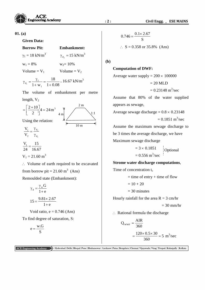
The volume of embankment per metre
length, V2
3m2442
102
Using the relation:
1
2
d
d
2
1
V
V
67.16
15
24
V1
V1 = 21.60 m3
Volume of earth required to be excavated
from borrow pit = 21.60 m3 (Ans)
Remoulded state (Embankment):
e1
Gwd
e1
67.281.915
Void ratio, e = 0.746 (Ans)
To find degree of saturation, S:
S
G.we
S
67.21.0746.0
S = 0.358 or 35.8% (Ans)
(b)
Computation of DWF:
Average water supply = 200 100000
= 20 MLD
= 0.23148 m3/sec
Assume that 80% of the water supplied
appears as sewage,
Average sewage discharge = 0.8 0.23148
= 0.1851 m3/sec
Assume the maximum sewage discharge to
be 3 times the average discharge, we have
Maximum sewage discharge
= 3 0.1851
= 0.556 m3/sec
Strome water discharge computations,
Time of concentration tc
= time of entry + time of flow
= 10 + 20
= 30 minutes
Hourly rainfall for the area R = 3 cm/hr
= 30 mm/hr
Rational formula the discharge
360
AIRQWWF
5360
305.0120
m3/sec
Optional
10 m
4 m
2 m
1:1
: 3 : Test – 6
ACE Engineering Academy Hyderabad|Delhi|Bhopal|Pune|Bhubaneswar| Lucknow|Patna|Bengaluru|Chennai|Vijayawada|Vizag|Tirupati|Kukatpally |Kolkata
The combined maximum discharge
Q = QDWF + QWWF
= 0.556 + 5
= 5.556 m3/sec
Now the sewer to be running half at the
maximum velocity 3 m/sec at the time of
maximum flow.
Area required =Velocity
Q
3
556.5
= 1.852 m2
Area of the sewer running half 2d8
A
2d8
852.1
d = 2.1716 m
Hence, use a sewer pipe of 2.1716 m dia
(c)
Given:
BG track, V = 75 kmph
Axle load = 24 tonnes
No. of driving wheels = 4 pairs
Total weight of driving wheels
= 4 24
= 96 tonnes
Hauling capacity 6
1 total weight of
driving wheels
= 966
1 = 16 tonnes
Let, W = total train load in tonnes
Total tractive resistance
C321 RRtRtRt
Where,
1Rt = Resistance independent on speed (or)
rolling resistance
Rt2 = Resistance dependent on speed
Rt3 = Atmospheric resistance
Rc = Resistance due to curve
Rt1 = 0.0016 W
Rt2 = 0.00008 W 75
Rt3 = 0.0000006 W 752
RC = 0.0004W 2
To find (W):
Hauling capacity = total tractive resistance
16 = 0.0016 W + 0.00008 75 W +
0.0000006 W 752 + 0.0004 W 2
W = 1358.81 tonnes
02.
(a) Preliminary analysis data given:Ultimate settlement, Sf = 250 mm
Time, t = 6 yearsSettlement, S = 50 mm
Ultimate settlement, Sf = mv. H. In the present case, the coefficient of volumecompressibility, mv is assumed to beconstant. Sf depends on H and Thickness increased by 20%. Hence theactual thickness is 1.2 HDue to lowering of W.T, the effective stressincreases.
: 4 : Civil Engg. _ ESE MAINS
ACE Engineering Academy Hyderabad|Delhi|Bhopal|Pune|Bhubaneswar| Lucknow|Patna|Bengaluru|Chennai|Vijayawada|Vizag|Tirupati|Kukatpally |Kolkata
The increase in effective stress = ( – ) h
Where h is the depth of lowering of W.T.As the is not given, let us assume that
≃ sat
Hence = (sat – ) h = wh = 9.81 1 = 9.81 kN/m2
Initial condition:Thickness = H1
Increase in stress: 1 = 24 kPaFinal settlement = mm250S
1f
Changed condition:Thickness, H2 = 1.2 H1
Increase in stress, 2 = 24 + 9.81 = 33.81 kPa
Final settlement =2fS
H..mS vf Sf . H(Assuming mv constant in the present case)
1
2
1
2
f
f
H
H.
S
S
1
2
1
1f
H
H2.1
24
81.33
250
S2
63.422S2f mm
Ultimate settlement under the actual siteconditions = 422.63 mm (Ans)
To find settlement at 2 years aftercompletion of building:Consolidation settlement time is reckonedfrom the middle of construction period
years5.12
3
Initial condition:t1 = 6 yearsS1 = 50 mm
100S
SU
f
11
%20100250
50
Changed condition:t2 = 1.5 + 2 = 3.5 yearsTo find settlement, S2
degree of consolidation = U22
1V 100
U
4T
1
0314.0100
20
4
2
We know that2
vv d
t.CT
2v d
tT
2
2
1
1
2
v
v
d
d
t
t
T
T
1
2
2V
H2.1
H
6
5.3
0314.0
T2
0127.0T2v
2
2v 100
U
4T
2
2
2
100
U
40127.0
U2 = 12.72%
100S
SU
2f
22
mm76.53S
10063.422
S72.12
2
2
Consolidation settlement after 2 years ofcompletion of building for the changedconditions = 53.76 mm (Ans)

: 5 : Test – 6
ACE Engineering Academy Hyderabad|Delhi|Bhopal|Pune|Bhubaneswar| Lucknow|Patna|Bengaluru|Chennai|Vijayawada|Vizag|Tirupati|Kukatpally |Kolkata
: 6 : Civil Engg. _ ESE MAINS
ACE Engineering Academy Hyderabad|Delhi|Bhopal|Pune|Bhubaneswar| Lucknow|Patna|Bengaluru|Chennai|Vijayawada|Vizag|Tirupati|Kukatpally |Kolkata
(b) (i)
At a certain temperature, the rate of
deoxygenation is assumed to be directly
proportional to the amount of organic matter
present in sewage at that time.; i.e.
tt KL
dt
dL
Where Lt = Oxygen equivalent of
carbonaceous oxidisable organic matter
present in sewage after t days from the start
of oxidation, in mg/l.
t = time in days
K = rate constant signifying the rate of
oxidation of organic matter and it
depends upon the nature of organic
matter and temperature. Its unit is per
day.
Integrating we get
dt.KL
dL
t
t
Loge Lt = –K. t + C
Where C is a constant of integration, and can
be evaluated from the boundary conditions
at the start i.e.
When t = 0 ,Lt = L (say)
Substituting in equation we have
Loge L = K(0) +C
C = loge L
Substituting this value of C in equation we
get
loge Lt = – K.t + logeL
loge Lt – loge L = – K.t
KtL
Llog t
e
Where KD is the De-oxygenation constant or
more strictly, the BOD rate constant
t.KL
Llog D
t10
tKt DeL
L
Now, L is the organic matter present at the
start of BOD reaction, (expressed as oxygen
equivalent) and Lt is the organic matter left
after t days; which means that during t days,
the quantity of organic matter oxidized
= L – Lt
If Yt represents the total amount of organic
matter oxidized in t days (i.e the BOD of t
days), then we have
Yt = L – Lt
We have
L
L1LY t
t
L
L1
L
Y tt
L
Y1
L
L tt
Substituting this value ofL
L t in equation we
get
: 7 : Test – 6
ACE Engineering Academy Hyderabad|Delhi|Bhopal|Pune|Bhubaneswar| Lucknow|Patna|Bengaluru|Chennai|Vijayawada|Vizag|Tirupati|Kukatpally |Kolkata
t.kt DeL
Y1
tKt De1L
L
tKt
De1LY
(ii)
Depletion of oxygen is (DOfinal – DOinitial)
= 4 ppm
5-day BOD at C20o oc20
5y
DFDODO initialfinal
DF = Dilution factor
= 2% of total sewage sample
502
100
5-day BOD = 4 50
= 200 mg/lit
We know the 5-day BOD at 20oC
kto
205 e1y
200 = lo (1 – e–0.23 5)
Where lo = ultimate BOD
Ultimate BOD lo = 292.67 mg/lit
03. (a) (i)
Ans:
Sleeper density:
The number of sleepers per rail length is
called sleeper density.
The spacing of sleepers is generally indicated
by a formula (n+x) where n is the length of
the rail in meter and x is a number 4, 5, 6 or 7
depending upon importance.
The sleeper density varies according to the
following factors.
1. Speed and axle load
2. Type of rail section
3. Type of sleepers
4. Type and depth of ballast
5. Bearing area of sleeper on ballast
6. Nature of formation
(ii)
Sol: Given BG, track
e = 12.5 cm
Vmax = 95 kmph
Do = 4o
As per Indian Railway
The length of transition curved based on
following
(1) Based on arbitrary gradient 1 in 720
L = 7.20e
L = 7.20 12.5
L = 90 m
(2) Based on rate of change of cant deficiency
L = 0.073 DVmax
D = cant deficiency in cm
D = 7.5 cm [Assumed for BG track]
L = 0.073 7.5 95
L = 52 m
: 8 : Civil Engg. _ ESE MAINS
ACE Engineering Academy Hyderabad|Delhi|Bhopal|Pune|Bhubaneswar| Lucknow|Patna|Bengaluru|Chennai|Vijayawada|Vizag|Tirupati|Kukatpally |Kolkata
(3) Based on rate of change of super elevation
L = 0.073eVmax
L = 0.073 12.5 95
L = 86.68 m
Take maximum of three
L = 90 m
To calculate offsets at every 15 m interval
oD
1720R
Where, Do = Degree of curve
Do = 4o
m4304
1720R
Cubic parabola equation for transition curve
RL6
xy
3
Taking offsets at 15m interval
m0145.0904306
15y
3
15
m116.0904306
30y
3
30
m392.0904306
45y
3
45
m93.0904306
60y
3
60
m817.1904306
75y
3
75
m14.3904306
90y
3
90
Shift of the circular curve
R24
LS
2
43024
90S
2
S = 0.785 m
03.(b) There are two types of piping failures
1. Backward erosion piping failure2. Heave piping failure
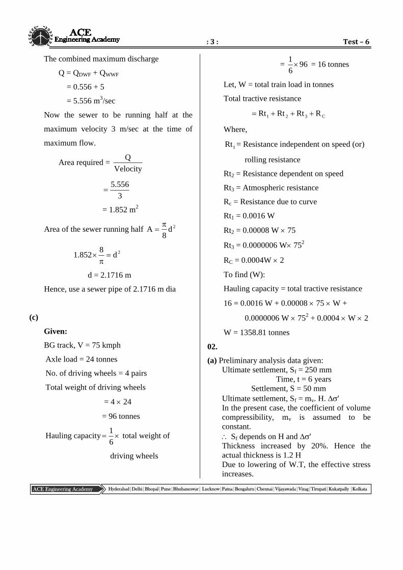
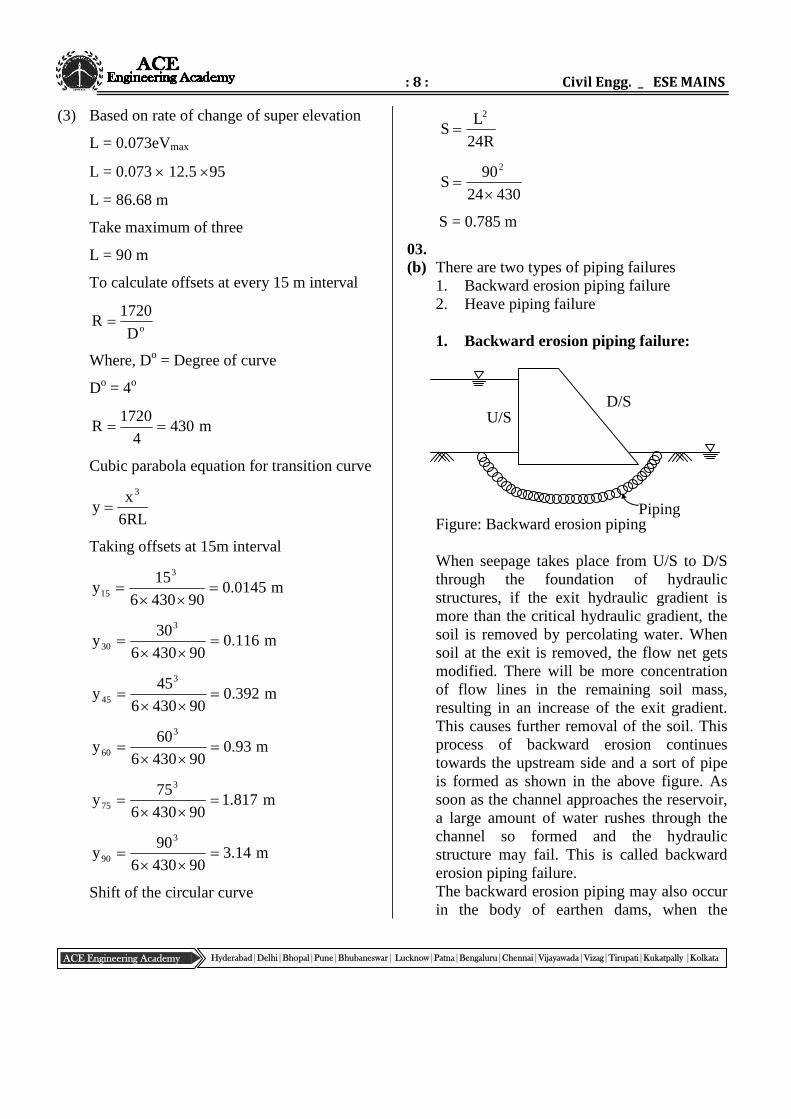
1. Backward erosion piping failure:
Figure: Backward erosion piping
When seepage takes place from U/S to D/Sthrough the foundation of hydraulicstructures, if the exit hydraulic gradient ismore than the critical hydraulic gradient, thesoil is removed by percolating water. Whensoil at the exit is removed, the flow net getsmodified. There will be more concentrationof flow lines in the remaining soil mass,resulting in an increase of the exit gradient.This causes further removal of the soil. Thisprocess of backward erosion continuestowards the upstream side and a sort of pipeis formed as shown in the above figure. Assoon as the channel approaches the reservoir,a large amount of water rushes through thechannel so formed and the hydraulicstructure may fail. This is called backwarderosion piping failure.The backward erosion piping may also occurin the body of earthen dams, when the
D/SU/S
Piping
: 9 : Test – 6
ACE Engineering Academy Hyderabad|Delhi|Bhopal|Pune|Bhubaneswar| Lucknow|Patna|Bengaluru|Chennai|Vijayawada|Vizag|Tirupati|Kukatpally |Kolkata
phreatic line cuts the down stream face of thedam and seepage pressure is high.
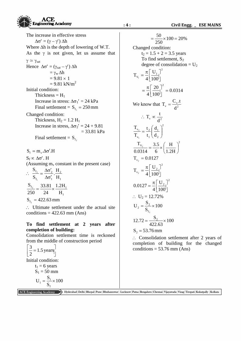
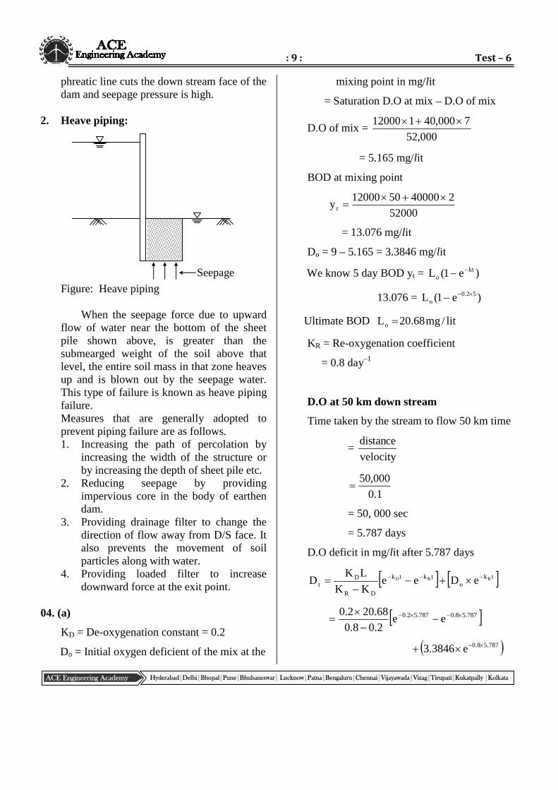
2. Heave piping:
Figure: Heave piping
When the seepage force due to upwardflow of water near the bottom of the sheetpile shown above, is greater than thesubmearged weight of the soil above thatlevel, the entire soil mass in that zone heavesup and is blown out by the seepage water.This type of failure is known as heave pipingfailure.Measures that are generally adopted toprevent piping failure are as follows.1. Increasing the path of percolation by
increasing the width of the structure orby increasing the depth of sheet pile etc.
2. Reducing seepage by providingimpervious core in the body of earthendam.
3. Providing drainage filter to change thedirection of flow away from D/S face. Italso prevents the movement of soilparticles along with water.
4. Providing loaded filter to increasedownward force at the exit point.
04. (a)
KD = De-oxygenation constant = 0.2
Do = Initial oxygen deficient of the mix at the
mixing point in mg/lit
= Saturation D.O at mix – D.O of mix
D.O of mix =000,52
7000,40112000
= 5.165 mg/lit
BOD at mixing point
52000
2400005012000y t
= 13.076 mg/lit
Do = 9 – 5.165 = 3.3846 mg/lit
We know 5 day BOD yt = )e1(L kto
13.076 = )e1(L 52.0o
Ultimate BOD lit/mg68.20Lo
KR = Re-oxygenation coefficient
= 0.8 day–1
D.O at 50 km down stream
Time taken by the stream to flow 50 km time
=velocity
cetandis
1.0
000,50
= 50, 000 sec
= 5.787 days
D.O deficit in mg/lit after 5.787 days
tko
tktk
DR
Dt
RRD eDeeKK
LKD
787.58.0787.52.0 ee2.08.0
68.202.0
787.58.0e3846.3
Seepage
: 10 : Civil Engg. _ ESE MAINS
ACE Engineering Academy Hyderabad|Delhi|Bhopal|Pune|Bhubaneswar| Lucknow|Patna|Bengaluru|Chennai|Vijayawada|Vizag|Tirupati|Kukatpally |Kolkata
= 2.1 + 0.03
= 2.13 mg/lit
D.O at 50 km down
= (DO initial – DO deficient)
= 5.165 – 2.13
= 3.035 mg/lit
D.O at 100 km down stream:
Time taken by the stream to travel 100 km
down stream sec0000,1001.0
0000,10t
= 11.574 days
D.O deficit in mg/lit after 11.574 days
tko
tktk
DR
oD RRD eDeeKK
LKDt
574.118.0574.112.0 ee2.08.0
68.202.0
+ 3.3846 e–0.8 11.574
= 0.6803 mg/lit
D.O at 100 km down stream
= (D.O initial – D.O deficient)
= 5.165 – 0.6803
= 4.4846 mg/lit
The time (tc) after which critical D.O deficit
(Dc) occurs is given by
f
L
D1f1log
1fK
1t o
eD
c
(or)
oD
DRo
D
R
DRc LK
KKD1
K
Kn
KK
1t
KR = 0.8
KD = 0.2
4K
Kf
D
R
Lo = 20.68 mg/lit
Do = 3.3846 mg/lit
4
68.203846.3
141log142.0
1t ec
= 1.185 days
Distance = Velocity Travel time
= 0.1 1.185 3600 24
= 10.238 km
Critical deficient
cD tkoc e
fL
D
185.12.0e4
678.20
Dc = 4.0786
Hence critical D.O deficit equal to 4.0786
mg/lit at 10.238 m down stream of A after
1.185 days.
: 11 : Test – 6
ACE Engineering Academy Hyderabad|Delhi|Bhopal|Pune|Bhubaneswar| Lucknow|Patna|Bengaluru|Chennai|Vijayawada|Vizag|Tirupati|Kukatpally |Kolkata
: 12 : Civil Engg. _ ESE MAINS
ACE Engineering Academy Hyderabad|Delhi|Bhopal|Pune|Bhubaneswar| Lucknow|Patna|Bengaluru|Chennai|Vijayawada|Vizag|Tirupati|Kukatpally |Kolkata
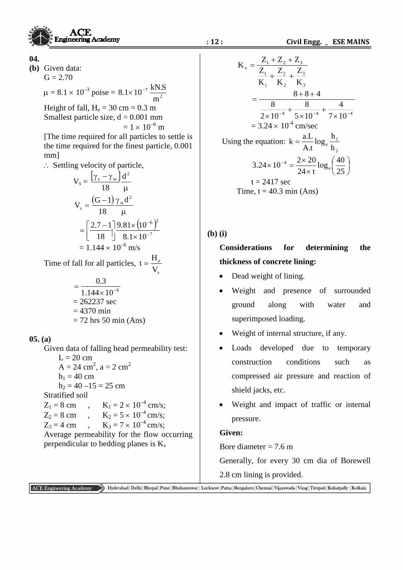
04.(b) Given data:
G = 2.70
= 8.1 10–3 poise =2
7
m
S.kN101.8
Height of fall, He = 30 cm = 0.3 mSmallest particle size, d = 0.001 mm
= 1 10–6 m[The time required for all particles to settle isthe time required for the finest particle, 0.001mm] Settling velocity of particle,
Vs =
2
ws d
18
2
ws
d
18
1GV
7
26
101.8
1081.9
18
17.2
= 1.144 10–6 m/s
Time of fall for all particles,s
e
V
Ht
610144.1
3.0
= 262237 sec= 4370 min= 72 hrs 50 min (Ans)
05. (a)Given data of falling head permeability test:
L = 20 cmA = 24 cm2, a = 2 cm2
h1 = 40 cmh2 = 40 –15 = 25 cm
Stratified soilZ1 = 8 cm , K1 = 2 10–4 cm/s;Z2 = 8 cm , K2 = 5 10–4 cm/s;Z3 = 4 cm , K3 = 7 10–4 cm/s;Average permeability for the flow occurringperpendicular to bedding planes is Kv
3
3
2
2
1
1
321v
K
Z
K
Z
K
ZZZZ
K
444 107
4
105
8
102
8488
= 3.24 10-4 cm/sec
Using the equation:2
1e h
hlog
t.A
L.ak
25
40log
t24
2021024.3 e
4
t = 2417 secTime, t = 40.3 min (Ans)
(b) (i)
Considerations for determining the
thickness of concrete lining:
Dead weight of lining.
Weight and presence of surrounded
ground along with water and
superimposed loading.
Weight of internal structure, if any.
Loads developed due to temporary
construction conditions such as
compressed air pressure and reaction of
shield jacks, etc.
Weight and impact of traffic or internal
pressure.
Given:
Bore diameter = 7.6 m
Generally, for every 30 cm dia of Borewell
2.8 cm lining is provided.
: 13 : Test – 6
ACE Engineering Academy Hyderabad|Delhi|Bhopal|Pune|Bhubaneswar| Lucknow|Patna|Bengaluru|Chennai|Vijayawada|Vizag|Tirupati|Kukatpally |Kolkata
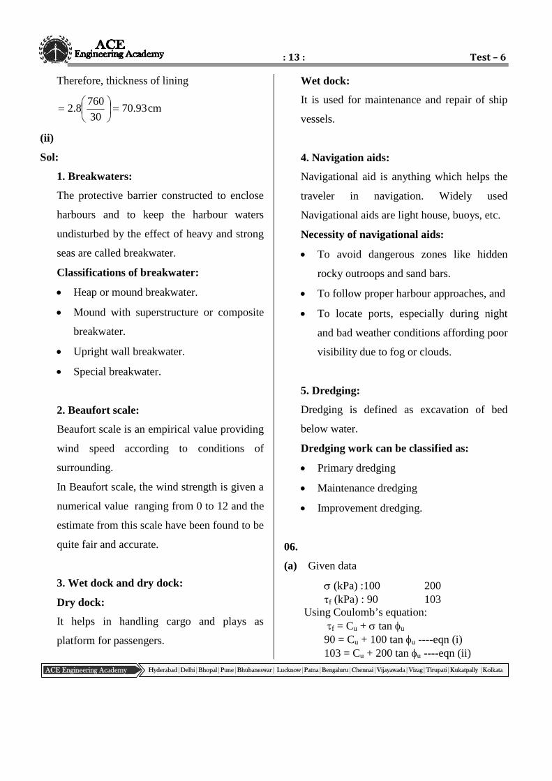
Therefore, thickness of lining
cm93.7030
7608.2
(ii)
Sol:
1. Breakwaters:
The protective barrier constructed to enclose
harbours and to keep the harbour waters
undisturbed by the effect of heavy and strong
seas are called breakwater.
Classifications of breakwater:
Heap or mound breakwater.
Mound with superstructure or composite
breakwater.
Upright wall breakwater.
Special breakwater.
2. Beaufort scale:
Beaufort scale is an empirical value providing
wind speed according to conditions of
surrounding.
In Beaufort scale, the wind strength is given a
numerical value ranging from 0 to 12 and the
estimate from this scale have been found to be
quite fair and accurate.
3. Wet dock and dry dock:
Dry dock:
It helps in handling cargo and plays as
platform for passengers.
Wet dock:
It is used for maintenance and repair of ship
vessels.
4. Navigation aids:
Navigational aid is anything which helps the
traveler in navigation. Widely used
Navigational aids are light house, buoys, etc.
Necessity of navigational aids:
To avoid dangerous zones like hidden
rocky outroops and sand bars.
To follow proper harbour approaches, and
To locate ports, especially during night
and bad weather conditions affording poor
visibility due to fog or clouds.
5. Dredging:
Dredging is defined as excavation of bed
below water.
Dredging work can be classified as:
Primary dredging
Maintenance dredging
Improvement dredging.
06.
(a) Given data
(kPa) :100 200f (kPa) : 90 103
Using Coulomb’s equation:f = Cu + tan u
90 = Cu + 100 tan u ----eqn (i)103 = Cu + 200 tan u ----eqn (ii)
: 14 : Civil Engg. _ ESE MAINS
ACE Engineering Academy Hyderabad|Delhi|Bhopal|Pune|Bhubaneswar| Lucknow|Patna|Bengaluru|Chennai|Vijayawada|Vizag|Tirupati|Kukatpally |Kolkata
Solving the above two equations,–13 = –100 tan u = 7.41o
Cu = 77 kPa (Ans)If the same soil is subjected to an unconfinedcompression test, the unconfinedcompressive strength (qu) is determined asfollows:
qu = 2 Cu tan
245 u
2
41.745tan772
= 175.33 kPaThe apparent cohesion of the unconfined
compression test,2
qC u
u
2
33.175
= 87.66 kPa (Ans)
(b)
Sol: Sewage Flow, Q = 5 MLD
70% of solids are removed at settling tank
Concentration of suspended solids
= 200 mg/lit
inST1 CQMsludgefreshin
solidsdryofamounttotal
day/kg700200100
705
watersolids1slu S
water%
S
solids%
)S(
100
1
98
5.2
2
)S(
100
1sludge
(Ssludge)1 = 1.0121
(sludge)1 = (Ssludge)1 w
= 1.0121 1000
= 1012.1 kg/m3
Volume of fresh sludge
1sludge
1
1f )(
M
)P100(
100V
P1 = 98% (M.C)
1.1012
700
98100
100Vf
= 34.58 m3
lit/mg70MLD5Msludgedigestedin
solidsdryofamoutTotal2
= 350 kg/day
P2 = 94
1
94
5.2
6
)S(
100
2sludge
(Ssludge)2 = 1.0373
(sludge)2 = (Ssludge)2 w
= 1.0373 1000
= 1037.3 kg/m3
Volume of digested sludge
2sludge
2
2d )S(
M
P100
100V
2sludge )(
)350(
94100
100
3.1037
350
6
100
= 5.6235 m3
Assuming sludge digested is linear and
digestion period t = 30 to 60 days (usually)
: 15 : Test – 6
ACE Engineering Academy Hyderabad|Delhi|Bhopal|Pune|Bhubaneswar| Lucknow|Patna|Bengaluru|Chennai|Vijayawada|Vizag|Tirupati|Kukatpally |Kolkata
Capacity of digester t2
VV df
302
6235.558.34
= 603.05 m3
(or) (Sludge digestion non linear capacity air
= (Vf –2/3 (Vf – Vd)t)
Depth = 10 m
Surface area of digester =depth
Volume
10
05.603 = 60.305 m2
305.60d4
Area 2
Dia of digester d2 = 76.78 m2
d = 8.76 m
07. (a) (i)
1. Taxiway:
The strip of pavement connecting the runway
to the apron or to the hanger is known as
taxiway. The standards for the design of
taxiway are not as rigid as those of the main
runway as the speed of the aircraft is much
slower along the taxiway. The taxiway
connects the runway ends to the aprons but
sometimes for smaller aircrafts taxiway exits
are provided in the middle of the runway too.
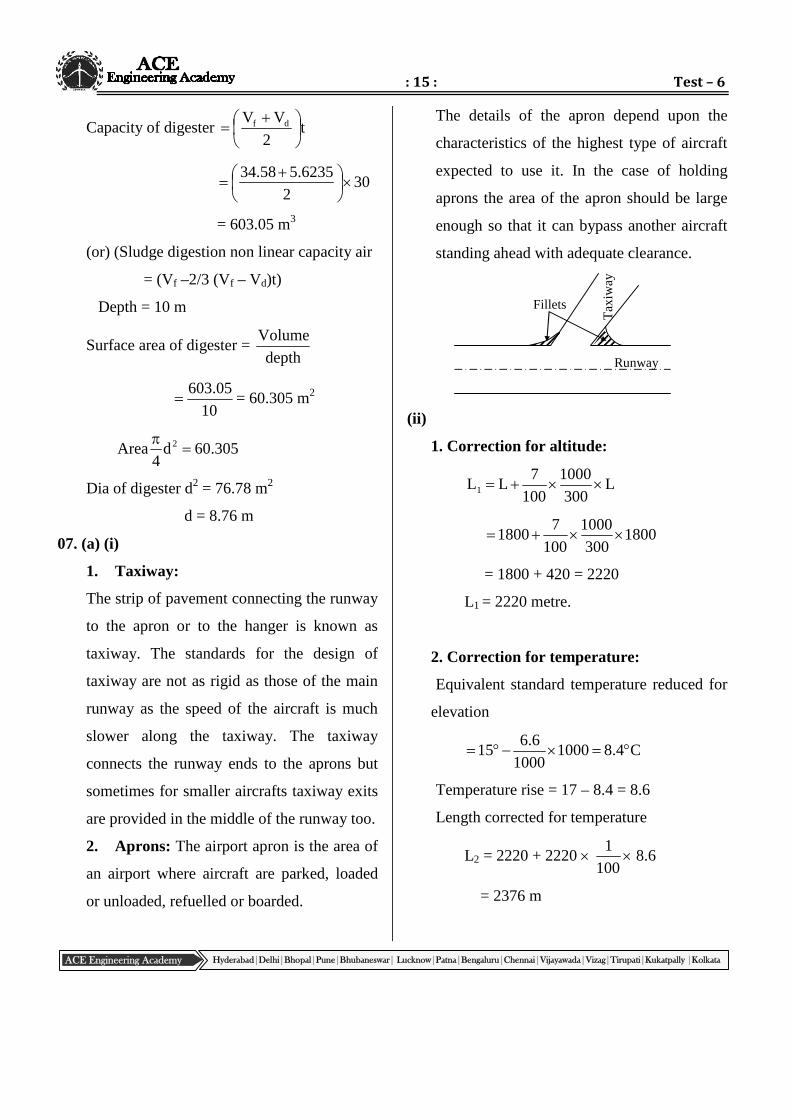
2. Aprons: The airport apron is the area of
an airport where aircraft are parked, loaded
or unloaded, refuelled or boarded.
The details of the apron depend upon the
characteristics of the highest type of aircraft
expected to use it. In the case of holding
aprons the area of the apron should be large
enough so that it can bypass another aircraft
standing ahead with adequate clearance.
(ii)
1. Correction for altitude:
L300
1000
100
7LL1
1800300
1000
100
71800
= 1800 + 420 = 2220
L1 = 2220 metre.
2. Correction for temperature:
Equivalent standard temperature reduced for
elevation
C4.810001000
6.615
Temperature rise = 17 – 8.4 = 8.6
Length corrected for temperature
L2 = 2220 + 2220 100
1 8.6
= 2376 m
Runway
Fillets
Tax
iway
: 16 : Civil Engg. _ ESE MAINS
ACE Engineering Academy Hyderabad|Delhi|Bhopal|Pune|Bhubaneswar| Lucknow|Patna|Bengaluru|Chennai|Vijayawada|Vizag|Tirupati|Kukatpally |Kolkata
3. Correction for gradient:
Increase at 2% for 1% effective gradient
5.0100
20LLL 223
10
123762376
= 2376 + 237.6
= 2613.6
= 2614 metre
For minimum clearance, length of runway
= 2614 + 120
= 2734 metres
Check:
Total correction for elevation, temperature
and gradient
= L2 – L
= 2376 – 1800
= 576 m
% increase 1001800
576 = 32%
(b) (i)
Sol: Assume the average daily sewage flow 150
lit/head (limit 135 to 200 lpcd)
Quantity of water supplied = Percapita rate
Population
= 200 150
= 30,000 l/day
Assuming that 75% (limit 75% to 80%
lpcd) of water supplied becomes sewage,
we have the quantity of sewage produced.
Quantity of sewage produced
= 0.75 × 150 × 200 l/day
= 22,500 l/d
Assume detention period is 30 hr (limit 28
hr to 48 hours)
Quantity of sewage produced during
detention time of 30 hrs
lit281253024
22500
= 28.125 m3
Now, assuming sludge deposition in the
tank @ 30 l/capita/yr (limit 30 to 40
lit/capita/yr) and cleaning period being 6
months, we have
Sludge volume
cum3it300012
620030
Total required capacity of the tank
= capacity of sewage + capacity of
sludge
Total capacity required = 28.125 + 3
= 31.125 m3.
Assuming 1.5 m depth,
Surface area 75.205.1
125.31 ≃ 2m21
Assuming the ratio of the length to width as
3 :1
L B = 21
3B2 = 21
B 7
B = 2.645 m
: 17 : Test – 6
ACE Engineering Academy Hyderabad|Delhi|Bhopal|Pune|Bhubaneswar| Lucknow|Patna|Bengaluru|Chennai|Vijayawada|Vizag|Tirupati|Kukatpally |Kolkata
L = 7.9 ≃ 8 m
Say, provide B = 2.645
Hence, use 8 m × 2.645 m × (1.5 + 0.3)m
sized septic tank.
(ii)
Sol: The quantity of sewage to be treated per day
= 0.8 250 10, 000
= 2 MLD
= 0.023 m3/sec
The BOD content per day = 2 200
= 400 kg
at latitude 20oN, the organic loading in the
pond as say 250 kg/hect/day
The surface area required
rateloadingOrganic
daypercontentBOD
250
400
= 1.8 hect
= 18000 m2
Assuming the length of the tank (L), as twice
of its width (B).
Area = LB = 18000
2 B2 =18000
B2 = 9000
B = 94.868 m ≃ 95 m
Length L = 189.73 m ≃ 190 m
Using a tank with effective depth as 1 m, we
have the provided capacity
= 190 95 1 m
= 18050 m3.
Detention time =flowSewage
Capacity
DT =2000
18050
= 9.025 days
≃ 9 days
Hence, use an oxidation pond with length
= 190 m,
Width 95 m and overall depth (1 + 1) = 2 m,
and detention period 9 days.
We know
Detention period in days
=
e
i
D y
ylog
K
1
=e
i
D y
yn
K
1
yi = Influent BOD
ye = Effluent BOD
ee y
200log
2.0
19
ye = 33.059 mg/lit
Effluent BOD = 33.059 mg/lit
: 18 : Civil Engg. _ ESE MAINS
ACE Engineering Academy Hyderabad|Delhi|Bhopal|Pune|Bhubaneswar| Lucknow|Patna|Bengaluru|Chennai|Vijayawada|Vizag|Tirupati|Kukatpally |Kolkata

: 19 : Test – 6
ACE Engineering Academy Hyderabad|Delhi|Bhopal|Pune|Bhubaneswar| Lucknow|Patna|Bengaluru|Chennai|Vijayawada|Vizag|Tirupati|Kukatpally |Kolkata

![Untitled-2 [katariyaindia.com]katariyaindia.com/brochure.pdf · industries. katariyå . Founder's message ... Pune Kolhapur Coimbatore Bhopal Katariya Piston Katariya Aluminium Hyderabad](https://static.fdocuments.net/doc/165x107/5f822cb097fdec2e973c055d/untitled-2-industries-katariy-founders-message-pune-kolhapur-coimbatore.jpg)


