ACE 4710 HA Configuration
14
Configuration Overview All contents are Copyright © 1992–2006 Cisco Systems, Inc. All rights reserved. This document is Cisco Public Information. Page 1 of 14 Cisco Application Control Engine (ACE) 4710 Appliance Configuration for High Availability The Cisco® Application Control Engine (ACE) 4710 Appliance provides a comprehensive application delivery solution, helps ensure application availability, accelerates application performance, and protects applications while simultaneously reducing data center costs. Take full advantage of new and enhanced purpose-built hardware to help lower your total cost of ownership (TCO) and improve both end-user and IT productivity. Overview The Cisco ACE 4710 appliance provides maximized application availability to help ensure business continuity and the best service to end users by taking advantage of availability through highly scalable Layer 4 load balancing and Layer 7 content switching, and minimizes effects of application, device, or Web site failure. The Cisco ACE 4710 appliance provides accelerated performance of Web-based applications by using patented acceleration technologies and delivers highly efficient data compression to speed up application response times; improve server performance by offloading Secure Sockets Layer (SSL) and TCP. The Cisco ACE 4710 appliance acts as a last line of server defense by providing protection against application threats and denial- of-service (DoS) attacks with features such as deep packet inspection, network and protocol security, and highly scalable access control capabilities. This provides lower total cost of ownership and minimizes costs by reducing the number of required servers and load balancers, lowers power and cooling requirements, increases IT productivity, and provides faster application deployments by taking advantage of the unique virtualized architecture. This configuration overview, targeted at enterprise and service provider customers, helps ensure the optimized and secure delivery of mission-critical application traffic in a highly available environment. This document provides a best practice example of how to configure the Cisco ACE 4710 appliance in a high available environment. Challenge Maintaining application availability and ensuring business continuity is a major concern of IT administrators. Companies are challenged to keep up with demand as more viewers access their Web sites. Seasonal fluctuations and concentrated marketing campaigns that generate a flood of Web traffic provide infrastructure and scaling challenges. Real-time tracking of how servers are performing is crucial to making sure that Web sites are serving up content in a timely fashion. However, accurate real-time tracking could be challenging with large server farms. Many mission- critical applications require transparent failover to occur within a second of a system becoming unresponsive. Website and server uptime is critical for supporting business revenue and driving profits. Highly available services ensure that viewers can access a company’s Web site and applications without interruption. Client trust can be built and reinforced by a site’s availability, as users are unlikely to return again if the site is occasionally offline, experience performance degradation, or is inaccessible. Business Benefits
description
ACE 4710 HA FT Configuration
Transcript of ACE 4710 HA Configuration
Configuration Overview
All contents are Copyright © 1992–2006 Cisco Systems, Inc. All rights reserved. This document is Cisco Public Information. Page 1 of 14
Cisco Application Control Engine (ACE) 4710 Appliance Configuration for High Availability
The Cisco® Application Control Engine (ACE) 4710 Appliance provides a comprehensive application delivery solution, helps ensure application availability, accelerates application performance, and protects applications while simultaneously reducing data center costs. Take full advantage of new and enhanced purpose-built hardware to help lower your total cost of ownership (TCO) and improve both end-user and IT productivity.
Overview
The Cisco ACE 4710 appliance provides maximized application availability to help ensure business continuity and the best service to end users by taking advantage of availability through highly scalable Layer 4 load balancing and Layer 7 content switching, and minimizes effects of application, device, or Web site failure. The Cisco ACE 4710 appliance provides accelerated performance of Web-based applications by using patented acceleration technologies and delivers highly efficient data compression to speed up application response times; improve server performance by offloading Secure Sockets Layer (SSL) and TCP. The Cisco ACE 4710 appliance acts as a last line of server defense by providing protection against application threats and denial-of-service (DoS) attacks with features such as deep packet inspection, network and protocol security, and highly scalable access control capabilities. This provides lower total cost of ownership and minimizes costs by reducing the number of required servers and load balancers, lowers power and cooling requirements, increases IT productivity, and provides faster application deployments by taking advantage of the unique virtualized architecture. This configuration overview, targeted at enterprise and service provider customers, helps ensure the optimized and secure delivery of mission-critical application traffic in a highly available environment. This document provides a best practice example of how to configure the Cisco ACE 4710 appliance in a high available environment.
Challenge
Maintaining application availability and ensuring business continuity is a major concern of IT administrators. Companies are challenged to keep up with demand as more viewers access their Web sites. Seasonal fluctuations and concentrated marketing campaigns that generate a flood of Web traffic provide infrastructure and scaling challenges. Real-time tracking of how servers are performing is crucial to making sure that Web sites are serving up content in a timely fashion. However, accurate real-time tracking could be challenging with large server farms. Many mission-critical applications require transparent failover to occur within a second of a system becoming unresponsive. Website and server uptime is critical for supporting business revenue and driving profits. Highly available services ensure that viewers can access a company’s Web site and applications without interruption. Client trust can be built and reinforced by a site’s availability, as users are unlikely to return again if the site is occasionally offline, experience performance degradation, or is inaccessible.
Business Benefits

Configuration Overview
All contents are Copyright © 1992–2006 Cisco Systems, Inc. All rights reserved. This document is Cisco Public Information. Page 2 of 14
The Cisco ACE 4710 appliance configuration for high availability provides all the elements needed to mitigate these challenges. The Cisco ACE 4710 Appliance offers the following major benefits:
• Scalability: The Cisco ACE 4710 appliance enables transparent scaling of Web sites and applications. New Web sites and application services can be deployed on the Cisco ACE 4710 appliance without disruption to existing services. This could be done by implementing virtualization on the Cisco ACE 4710 appliance. This provides an effective method of adding new Web sites and application services during seasonal fluctuations and concentrated marketing campaigns and resolves the challenge of keeping up with demand as more viewers access their Web sites and applications. The Cisco ACE 4710 appliance has four physical gigabit Ethernet interfaces supporting port channeling and dot1q trunking. This provides you the ability to channel and trunk any combination of VLANs accessing all four physical interfaces. With the combination of trunked VLANs and port-channeled interfaces this provides the best level of interface and device scalability available today.
• Virtualization: Virtualization is the ability to logically partition a single physical device into many virtual contexts. Each virtual context must has all the capabilities of the actual physical device, and each virtual context is independent and isolated so that it appears to be a unique physical device from the viewpoint of the network and the network administrator. With virtualization, each virtual context can be allocated its own resources and quality of service (QoS) with bursting capability to the virtual IP address (VIP) or real IP address (RIP) level if desired. Each virtual context can also be assigned its own configuration files, management interfaces, and access-control policies in which access control privileges are assigned to users based on their administrative roles.
• Availability and reliability: The Cisco ACE 4710 appliance uses a highly robust architecture. This architecture provides separation of the control and data paths, helping to ensure separation of device control and connection management. The Cisco ACE 4710 appliance could be implemented either in Active/Active or Active/Standby using virtualization. This implementation allows you to distribute processing across both appliances. The Cisco ACE 4710 appliance supports both stateful failover and the replication of the sticky entries per physical or virtual context. Stateful failover contains all the flow-state information necessary for the standby to take over if the active becomes unresponsive.
The Cisco ACE 4710 Appliance Solution
To maximize application and infrastructure availability, the Cisco ACE 4710 appliance takes advantage of all four gigabit Ethernet interfaces and ACE virtualization. These interfaces can be port-channeled together to create one logical connection between the Cisco ACE 4710 appliance and connected to Cisco Catalyst Series Switches. Trunked VLANs can be used to carry client/server messaging, management traffic and fault tolerance (FT) communication. Virtualization on the Cisco ACE 4710 appliance enables you to separate the FT configuration from the load balancing and optimization services. Except for interface and peer tracking, all FT configurations can be configured on the Admin context. This simplifies the FT configuration on the Cisco ACE 4710 appliances providing benefits for manageability and operations. This Admin virtual context would also be used for management. In this document the management VLAN 110 is also the native VLAN.
Configuration Overview
All contents are Copyright © 1992–2006 Cisco Systems, Inc. All rights reserved. This document is Cisco Public Information. Page 3 of 14
The Cisco ACE 4710 appliance will use the remaining gigabit Ethernet interfaces in the event of a link failure. As a result of using port channeling, no FT state will change unless all four gigabit Ethernet interfaces go down. With the addition of interface and peer tracking, failover can be detected earlier. You can configure the Cisco ACE 4710 appliance to track and detect failures of the gateways or hosts. FT gateway tracking can be enabled on the Cisco ACE 4710 appliance using an ICMP probe to automatically failover if the ICMP pings fails between ACE and connected Cisco Catalyst Series Switch. This configuration is configured within each virtual context. Therefore, if the FT gateway tracking ICMP ping fails, all virtual context will failover to the backup. For this to work effectively the Cisco ACE 4710 appliance requires preempt to be enabled and the priority set.
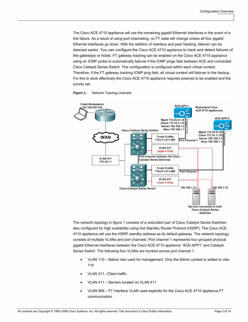
Figure 1. Network Topology example
The network topology in figure 1 consists of a redundant pair of Cisco Catalyst Series Switches also configured for high availability using Hot Standby Router Protocol (HSRP). The Cisco ACE 4710 appliance will use the HSRP standby address as its default gateway. The network topology consists of multiple VLANs and port channels. Port channel 1 represents four grouped physical gigabit Ethernet interfaces between the Cisco ACE 4710 appliance “ACE-APP1” and Catalyst Series Switch. The following four VLANs are trunked across port channel 1.
• VLAN 110 – Native vlan used for management. Only the Admin context is added to vlan 110
• VLAN 211 –Client traffic
• VLAN 411 – Servers located on VLAN 411
• VLAN 999 – FT Interface VLAN used explicitly for the Cisco ACE 4710 appliance FT communication
Configuration Overview
All contents are Copyright © 1992–2006 Cisco Systems, Inc. All rights reserved. This document is Cisco Public Information. Page 4 of 14
The port channel between the two Cisco Catalyst Series Switches will need to trunk all four VLANS plus any additional VLANs necessary. The Cisco ACE 4710 appliances are configured in routed mode. Therefore, the servers’ default gateway will use the alias IP address on interface VLAN 411 on the Cisco ACE 4710 appliance. The alias address is the same IP address on both “ACE-APP-1” and “ACE-APP-2”. Only the active Cisco ACE 4710 appliances or virtual context will forward client/server traffic. You can only ARP for the alias IP address once the FT group is inservice.
Looking at the network topology in figure 1, the Cisco ACE 4710 appliance configuration below, you will notice the FT configuration consists of three pieces. This includes the FT interface VLAN, FT peer and FT group. The FT interface VLAN, VLAN 999 is a designated VLAN between the two Cisco ACE 4710 appliances. All FT traffic is sent over this VLAN including:
● ACE redundancy protocol packets
● Heart Beats
● Configuration sync packets
● State replication packets
The election of the active Cisco ACE 4710 appliance within each FT group is based on a priority. The Cisco ACE 4710 appliance configured with the higher priority is elected as the active member. If a member with a higher priority is found after the other member becomes active, the new member becomes active because it has a higher priority. This behavior is known as preemption and is enabled by default. You can override this default behavior by disabling preemption. You can see from the configuration that ACE-APP1 has a higher priority. If priorities of both members are equal, the member with the higher IP address becomes active. If preempt is disabled, failover does not happen based on priorities.
Each FT group acts as an independent FT instance. It is recommended to create a unique FT group per virtual context. You will see from the configuration a virtual context is associated with each FT group. When a failover occurs, the active Cisco ACE 4710 appliance in the FT group now becomes standby and the original standby Cisco ACE 4710 appliance becomes active. Failover can occur for the following reasons:
● The active Cisco ACE 4710 appliance becomes unresponsive
● A FT gateway tracking host or interface fails
● You enter the ft switchover command to force a failover. This is per context level
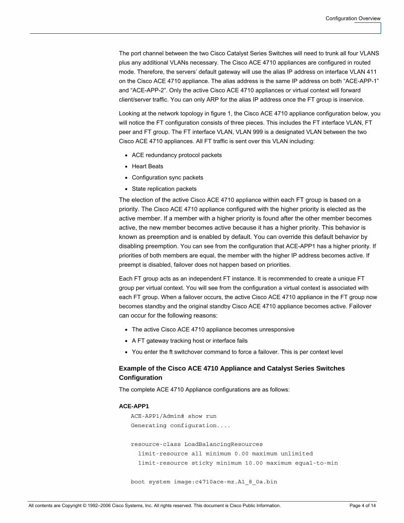
Example of the Cisco ACE 4710 Appliance and Catalyst Series Switches Configuration
The complete ACE 4710 Appliance configurations are as follows:
ACE-APP1 ACE-APP1/Admin# show run
Generating configuration....
resource-class LoadBalancingResources
limit-resource all minimum 0.00 maximum unlimited
limit-resource sticky minimum 10.00 maximum equal-to-min
boot system image:c4710ace-mz.A1_8_0a.bin
Configuration Overview
All contents are Copyright © 1992–2006 Cisco Systems, Inc. All rights reserved. This document is Cisco Public Information. Page 5 of 14
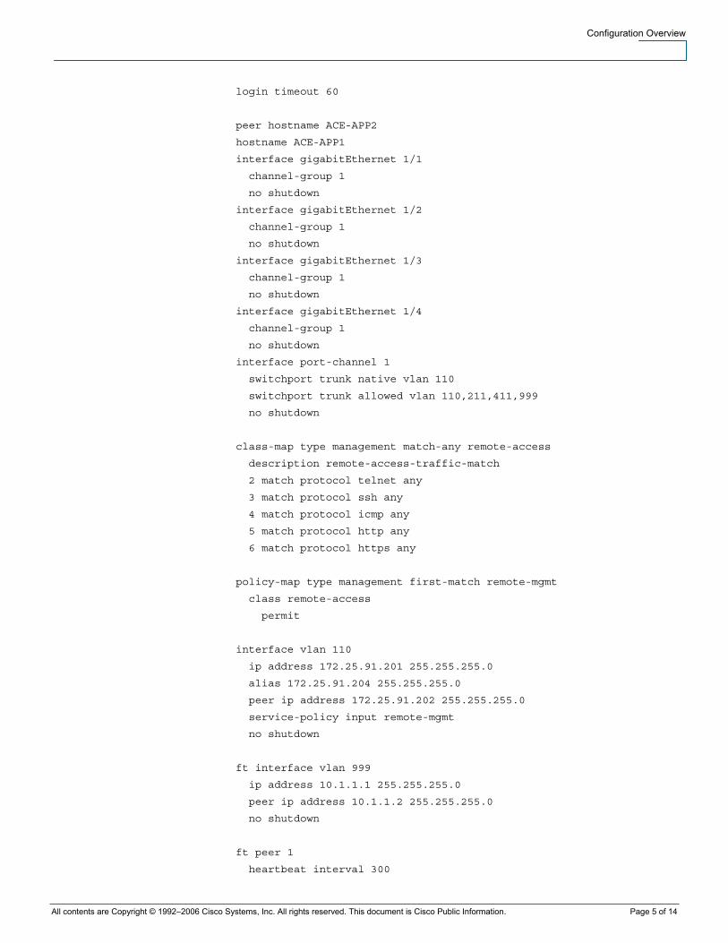
login timeout 60
peer hostname ACE-APP2
hostname ACE-APP1
interface gigabitEthernet 1/1
channel-group 1
no shutdown
interface gigabitEthernet 1/2
channel-group 1
no shutdown
interface gigabitEthernet 1/3
channel-group 1
no shutdown
interface gigabitEthernet 1/4
channel-group 1
no shutdown
interface port-channel 1
switchport trunk native vlan 110
switchport trunk allowed vlan 110,211,411,999
no shutdown
class-map type management match-any remote-access
description remote-access-traffic-match
2 match protocol telnet any
3 match protocol ssh any
4 match protocol icmp any
5 match protocol http any
6 match protocol https any
policy-map type management first-match remote-mgmt
class remote-access
permit
interface vlan 110
ip address 172.25.91.201 255.255.255.0
alias 172.25.91.204 255.255.255.0
peer ip address 172.25.91.202 255.255.255.0
service-policy input remote-mgmt
no shutdown
ft interface vlan 999
ip address 10.1.1.1 255.255.255.0
peer ip address 10.1.1.2 255.255.255.0
no shutdown
ft peer 1
heartbeat interval 300
Configuration Overview
All contents are Copyright © 1992–2006 Cisco Systems, Inc. All rights reserved. This document is Cisco Public Information. Page 6 of 14
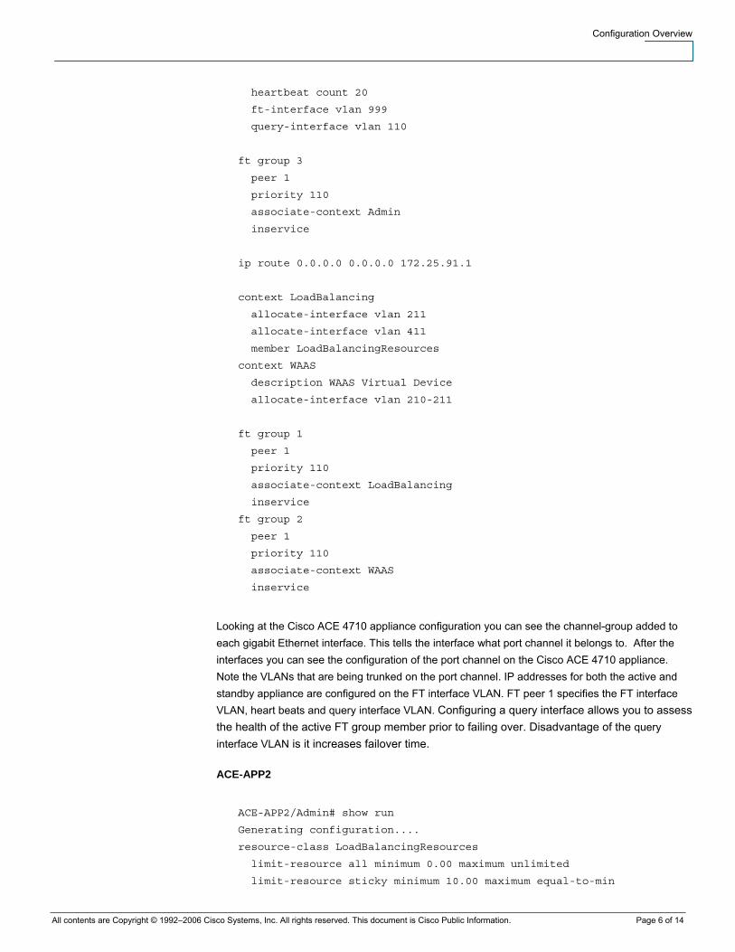
heartbeat count 20
ft-interface vlan 999
query-interface vlan 110
ft group 3
peer 1
priority 110
associate-context Admin
inservice
ip route 0.0.0.0 0.0.0.0 172.25.91.1
context LoadBalancing
allocate-interface vlan 211
allocate-interface vlan 411
member LoadBalancingResources
context WAAS
description WAAS Virtual Device
allocate-interface vlan 210-211
ft group 1
peer 1
priority 110
associate-context LoadBalancing
inservice
ft group 2
peer 1
priority 110
associate-context WAAS
inservice
Looking at the Cisco ACE 4710 appliance configuration you can see the channel-group added to each gigabit Ethernet interface. This tells the interface what port channel it belongs to. After the interfaces you can see the configuration of the port channel on the Cisco ACE 4710 appliance. Note the VLANs that are being trunked on the port channel. IP addresses for both the active and standby appliance are configured on the FT interface VLAN. FT peer 1 specifies the FT interface VLAN, heart beats and query interface VLAN. Configuring a query interface allows you to assess the health of the active FT group member prior to failing over. Disadvantage of the query interface VLAN is it increases failover time.
ACE-APP2
ACE-APP2/Admin# show run
Generating configuration....
resource-class LoadBalancingResources
limit-resource all minimum 0.00 maximum unlimited
limit-resource sticky minimum 10.00 maximum equal-to-min
Configuration Overview
All contents are Copyright © 1992–2006 Cisco Systems, Inc. All rights reserved. This document is Cisco Public Information. Page 7 of 14
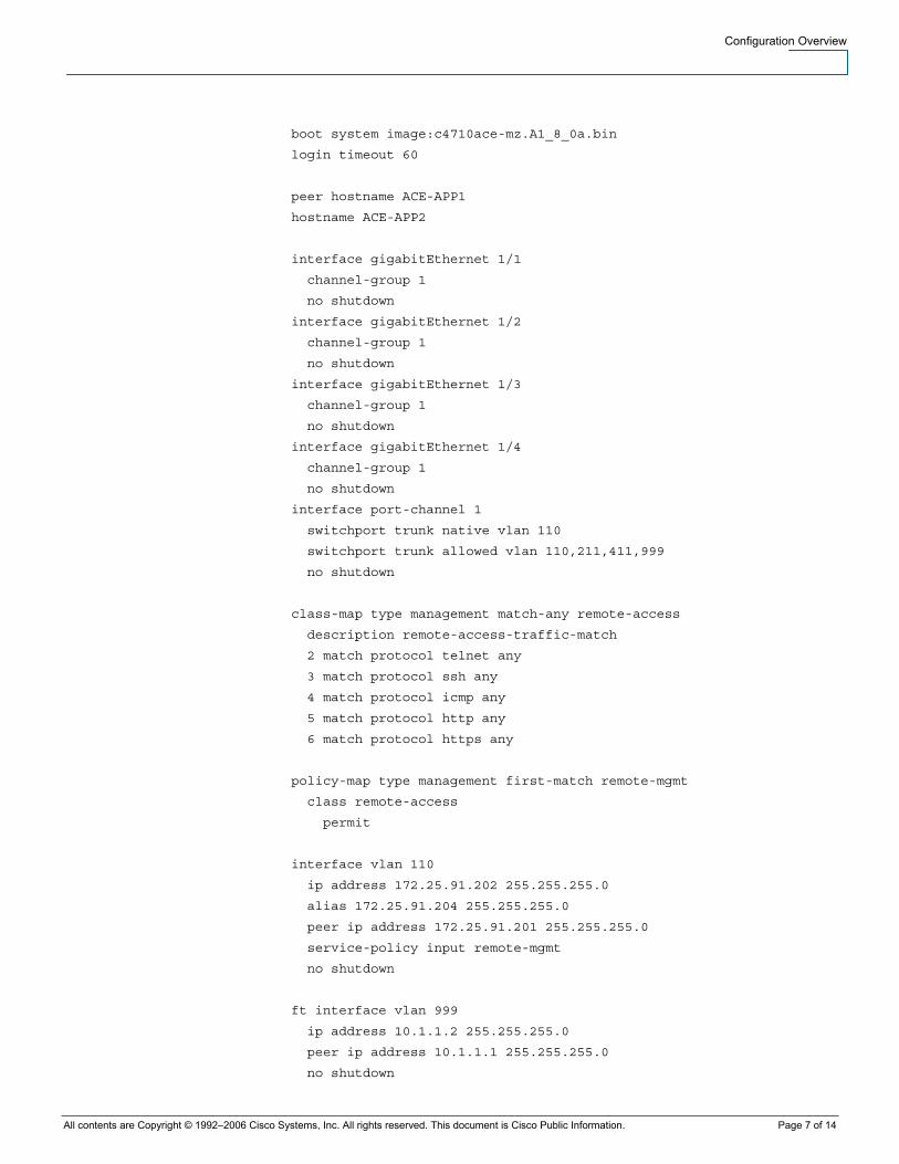
boot system image:c4710ace-mz.A1_8_0a.bin
login timeout 60
peer hostname ACE-APP1
hostname ACE-APP2
interface gigabitEthernet 1/1
channel-group 1
no shutdown
interface gigabitEthernet 1/2
channel-group 1
no shutdown
interface gigabitEthernet 1/3
channel-group 1
no shutdown
interface gigabitEthernet 1/4
channel-group 1
no shutdown
interface port-channel 1
switchport trunk native vlan 110
switchport trunk allowed vlan 110,211,411,999
no shutdown
class-map type management match-any remote-access
description remote-access-traffic-match
2 match protocol telnet any
3 match protocol ssh any
4 match protocol icmp any
5 match protocol http any
6 match protocol https any
policy-map type management first-match remote-mgmt
class remote-access
permit
interface vlan 110
ip address 172.25.91.202 255.255.255.0
alias 172.25.91.204 255.255.255.0
peer ip address 172.25.91.201 255.255.255.0
service-policy input remote-mgmt
no shutdown
ft interface vlan 999
ip address 10.1.1.2 255.255.255.0
peer ip address 10.1.1.1 255.255.255.0
no shutdown
Configuration Overview
All contents are Copyright © 1992–2006 Cisco Systems, Inc. All rights reserved. This document is Cisco Public Information. Page 8 of 14
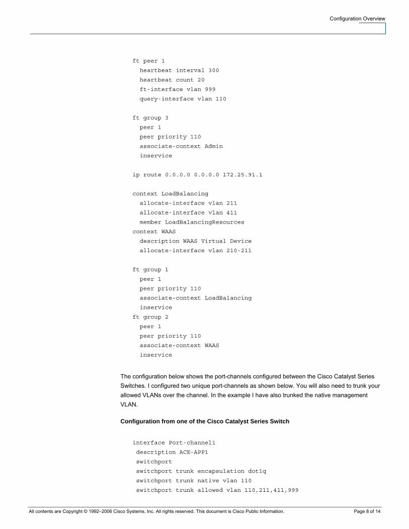
ft peer 1
heartbeat interval 300
heartbeat count 20
ft-interface vlan 999
query-interface vlan 110
ft group 3
peer 1
peer priority 110
associate-context Admin
inservice
ip route 0.0.0.0 0.0.0.0 172.25.91.1
context LoadBalancing
allocate-interface vlan 211
allocate-interface vlan 411
member LoadBalancingResources
context WAAS
description WAAS Virtual Device
allocate-interface vlan 210-211
ft group 1
peer 1
peer priority 110
associate-context LoadBalancing
inservice
ft group 2
peer 1
peer priority 110
associate-context WAAS
inservice
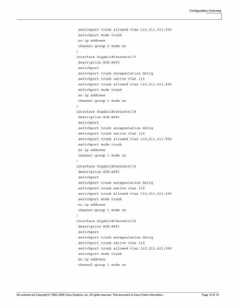
The configuration below shows the port-channels configured between the Cisco Catalyst Series Switches. I configured two unique port-channels as shown below. You will also need to trunk your allowed VLANs over the channel. In the example I have also trunked the native management VLAN.
Configuration from one of the Cisco Catalyst Series Switch
interface Port-channel1
description ACE-APP1
switchport
switchport trunk encapsulation dot1q
switchport trunk native vlan 110
switchport trunk allowed vlan 110,211,411,999
Configuration Overview
All contents are Copyright © 1992–2006 Cisco Systems, Inc. All rights reserved. This document is Cisco Public Information. Page 9 of 14
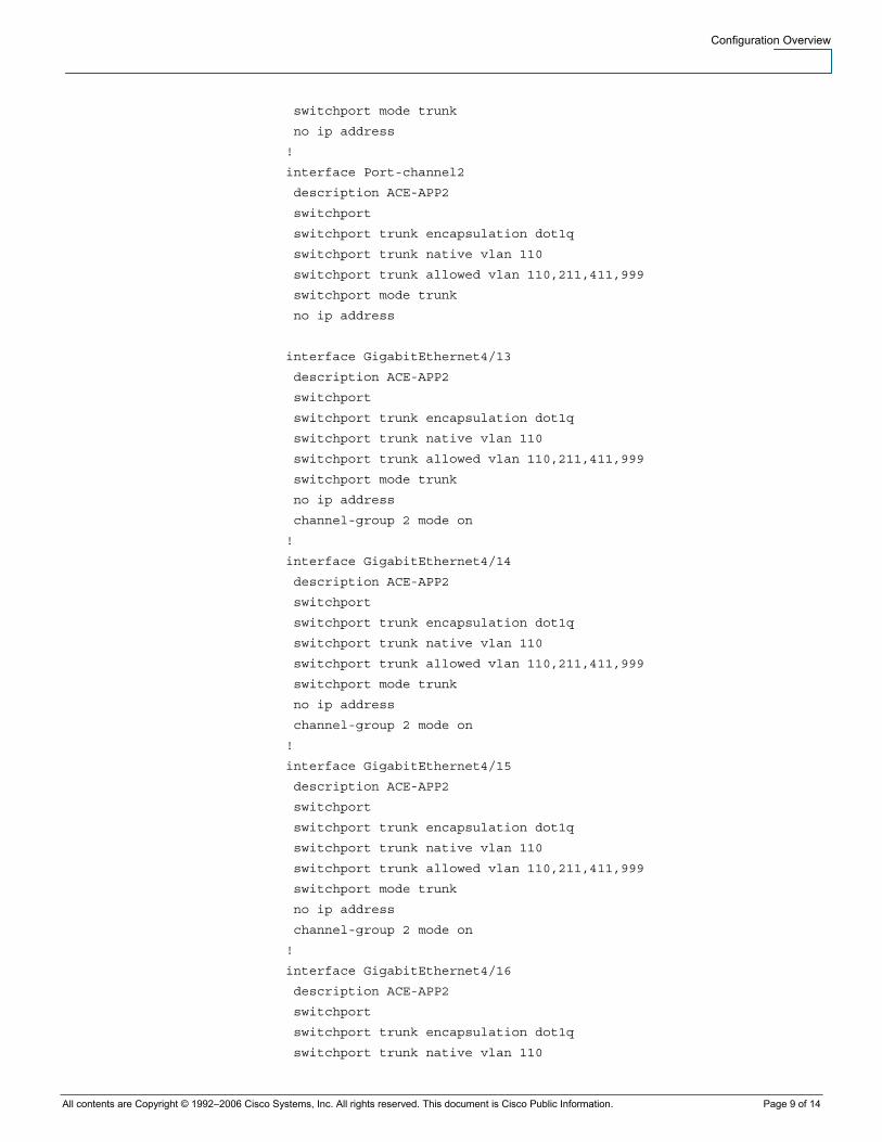
switchport mode trunk
no ip address
!
interface Port-channel2
description ACE-APP2
switchport
switchport trunk encapsulation dot1q
switchport trunk native vlan 110
switchport trunk allowed vlan 110,211,411,999
switchport mode trunk
no ip address
interface GigabitEthernet4/13
description ACE-APP2
switchport
switchport trunk encapsulation dot1q
switchport trunk native vlan 110
switchport trunk allowed vlan 110,211,411,999
switchport mode trunk
no ip address
channel-group 2 mode on
!
interface GigabitEthernet4/14
description ACE-APP2
switchport
switchport trunk encapsulation dot1q
switchport trunk native vlan 110
switchport trunk allowed vlan 110,211,411,999
switchport mode trunk
no ip address
channel-group 2 mode on
!
interface GigabitEthernet4/15
description ACE-APP2
switchport
switchport trunk encapsulation dot1q
switchport trunk native vlan 110
switchport trunk allowed vlan 110,211,411,999
switchport mode trunk
no ip address
channel-group 2 mode on
!
interface GigabitEthernet4/16
description ACE-APP2
switchport
switchport trunk encapsulation dot1q
switchport trunk native vlan 110
Configuration Overview
All contents are Copyright © 1992–2006 Cisco Systems, Inc. All rights reserved. This document is Cisco Public Information. Page 10 of 14
switchport trunk allowed vlan 110,211,411,999
switchport mode trunk
no ip address
channel-group 2 mode on
!
interface GigabitEthernet4/17
description ACE-APP1
switchport
switchport trunk encapsulation dot1q
switchport trunk native vlan 110
switchport trunk allowed vlan 110,211,411,999
switchport mode trunk
no ip address
channel-group 1 mode on
!
interface GigabitEthernet4/18
description ACE-APP1
switchport
switchport trunk encapsulation dot1q
switchport trunk native vlan 110
switchport trunk allowed vlan 110,211,411,999
switchport mode trunk
no ip address
channel-group 1 mode on
!
interface GigabitEthernet4/19
description ACE-APP1
switchport
switchport trunk encapsulation dot1q
switchport trunk native vlan 110
switchport trunk allowed vlan 110,211,411,999
switchport mode trunk
no ip address
channel-group 1 mode on
!
interface GigabitEthernet4/20
description ACE-APP1
switchport
switchport trunk encapsulation dot1q
switchport trunk native vlan 110
switchport trunk allowed vlan 110,211,411,999
switchport mode trunk
no ip address
channel-group 1 mode on
Configuration Overview
All contents are Copyright © 1992–2006 Cisco Systems, Inc. All rights reserved. This document is Cisco Public Information. Page 11 of 14
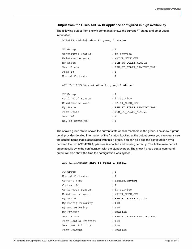
Output from the Cisco ACE 4710 Appliance configured in high availability
The following output from show ft commands shows the current FT status and other useful information:
ACE-APP1/Admin# show ft group 1 status
FT Group : 1
Configured Status : in-service
Maintenance mode : MAINT_MODE_OFF
My State : FSM_FT_STATE_ACTIVE
Peer State : FSM_FT_STATE_STANDBY_HOT
Peer Id : 1
No. of Contexts : 1
ACE-TME-APP2/Admin# show ft group 1 status
FT Group : 1
Configured Status : in-service
Maintenance mode : MAINT_MODE_OFF
My State : FSM_FT_STATE_STANDBY_HOT
Peer State : FSM_FT_STATE_ACTIVE
Peer Id : 1
No. of Contexts : 1
The show ft group status shows the current state of both members in the group. The show ft group detail provides detailed information of the ft status. Looking at the output below you can clearly see the context name that is associated with this ft group. You can also see the configuration sync between the two ACE 4710 Appliances is enabled and working correctly. The Active member will automatically sync the configuration with the standby peer. The show ft group status command output will also show the time the configuration was synced.
ACE-APP1/Admin# show ft group 1 detail
FT Group : 1
No. of Contexts : 1
Context Name : LoadBalancing
Context Id : 1
Configured Status : in-service
Maintenance mode : MAINT_MODE_OFF
My State : FSM_FT_STATE_ACTIVE
My Config Priority : 120
My Net Priority : 120
My Preempt : Enabled
Peer State : FSM_FT_STATE_STANDBY_HOT
Peer Config Priority : 110
Peer Net Priority : 110
Peer Preempt : Enabled

Configuration Overview
All contents are Copyright © 1992–2006 Cisco Systems, Inc. All rights reserved. This document is Cisco Public Information. Page 12 of 14
Peer Id : 1
Last State Change time : Tue Nov 6 20:57:29 2007
Running cfg sync enabled : Enabled
Running cfg sync status : Running configuration sync has completed
Startup cfg sync enabled : Enabled
Startup cfg sync status : Startup configuration sync has completed
Bulk sync done for ARP: 1
Bulk sync done for LB: 1
Bulk sync done for ICM: 1
ACE-APP2/Admin# show ft group 1 detail
FT Group : 1
No. of Contexts : 1
Context Name : LoadBalancing
Context Id : 1
Configured Status : in-service
Maintenance mode : MAINT_MODE_OFF
My State : FSM_FT_STATE_STANDBY_HOT
My Config Priority : 110
My Net Priority : 110
My Preempt : Enabled
Peer State : FSM_FT_STATE_ACTIVE
Peer Config Priority : 120
Peer Net Priority : 120
Peer Preempt : Enabled
Peer Id : 1
Last State Change time : Fri Nov 9 14:10:58 2007
Running cfg sync enabled : Enabled
Running cfg sync status : Running configuration sync has completed
Startup cfg sync enabled : Enabled
Startup cfg sync status : Startup configuration sync has completed
Bulk sync done for ARP: 1
Bulk sync done for LB: 1
Bulk sync done for ICM: 1
The show FT peer detail provides detailed information of the FT configuration between the two Cisco ACE 4710 appliances. This command shows the compatibility state between the two appliances. This is extremely important as if the two appliances are not compatible configuration synchronization will not work correctly. This applies to both version and license compatibility checking. The show FT peer detail also shows the query interface VLAN state. Another useful counter shown in this command is the PEER_DOWN counter. This shows how many times ACE has transitioned from master to backup. You can also see if FT keepalive packets are getting dropped based on the Tx/FX Keepalive Packets counter.

Configuration Overview
All contents are Copyright © 1992–2006 Cisco Systems, Inc. All rights reserved. This document is Cisco Public Information. Page 13 of 14
ACE-APP1/Admin# show ft peer 1 detail
Peer Id : 1
State : FSM_PEER_STATE_COMPATIBLE
Maintenance mode : MAINT_MODE_OFF
FT Vlan : 999
FT Vlan IF State : UP
My IP Addr : 10.1.1.1
Peer IP Addr : 10.1.1.2
Query Vlan : 110
Query Vlan IF State : UP
Peer Query IP Addr : 172.25.91.202
Heartbeat Interval : 300
Heartbeat Count : 20
Tx Packets : 22636
Tx Bytes : 4916852
Rx Packets : 22627
Rx Bytes : 4908377
Rx Error Bytes : 0
Tx Keepalive Packets : 22582
Rx Keepalive Packets : 22582
TL_CLOSE count : 0
FT_VLAN_DOWN count : 0
PEER_DOWN count : 3
SRG Compatibility : COMPATIBLE
License Compatibility : COMPATIBLE
FT Groups : 3
ACE-TME-APP1/Admin#
Conclusion
The Cisco ACE 4710 Appliance high availability configuration provides information technology administrators with a simplified solution. This solution is highly configurable and can be manipulated based on your requirements. Using trunking and port-channeling on the Cisco ACE 4710 Appliance this enables you to follow networking best practice and recommend high available configurations.
Why Cisco?
Cisco has been instrumental in development of high-availability standards and is a pioneer in the delivery of business application switching infrastructure and services. Cisco ANS is a unified portfolio of data center and wide-area solutions that secure, scale, optimize, and accelerate the delivery of internal- and external-facing applications. These products are comprehensively supported by a global network of Cisco field personnel and partners, online support, certified training programs, open discussion forums, and equipment replacement in as little as 4 hours.
For More Information
Cisco ACE Application Control Engine Solution for High Availability, visit http://cisco.com/en/US/products/hw/modules/ps2706/prod_brochure0900aecd806cecc5.html

Configuration Overview
All contents are Copyright © 1992–2006 Cisco Systems, Inc. All rights reserved. This document is Cisco Public Information. Page 14 of 14
For more information about Cisco Application Networking Services, Cisco data center solutions for Cisco ANS, and Cisco ACE, visit http://www.cisco.com/go/applicationservices or contact your local Cisco account representative.
Printed in USA C78-331727-01 10/06