ACCUMASS BW100 - Siemens Totalizer 1 15 Analog Output 15 Remote Totalizer 2 16 Relay Output 16...
84
ACCUMASS BW100 May 1997 Instruction Manual PL-531 33455310 Rev 1.1
Transcript of ACCUMASS BW100 - Siemens Totalizer 1 15 Analog Output 15 Remote Totalizer 2 16 Relay Output 16...

ACCUMASS BW100
May 1997
Instruction Manual
PL-531
33455310Rev 1.1

Thank you for purchasing Mass Dynamics’ products. We endeavour to design equipment
that is simple to use and reliable in its operation, with the aim of satisfying our customers’ needs.
Mass Dynamics was established in 1997 as a new business division of Milltornics Ltd..
It is dedicated to the sales and developement of continous weighing, acoustic sensing and
motion sensing equipment.
Mass Dynamics’ products are distributed through Milltronics’ world wide associate offices
and representatives. This network is continually being refined to provide our customers with
first rate sales information, engineering assistance and after sales support.
For more details on our products and service, please contact us and we will provide you with
a listing of the offices or representatives nearest you.
Canada : 1954 Technology Dr., P.O. Box 4225, Peterborough, Ontario, Canada K9J 7B1Tel.: 705-745-2431 Fax: 705-741-0466
U.S.A. : 709 Stadium Drive, Arlington, Texas U.S.A. 76011Tel.: 817-277-3543 Fax: 817-277-3894
England : Oak House, Bromyard Road, Worcester, England WR2 5XZ Tel.: 01905-748404 Fax: 01905-748430
France : Parc de la Sainte Victoire, Bât. 5, 13590 Meyreuil, FranceTel.: +33 4 42 65 69 00 Fax: +33 4 42 58 63 95
Belgium : August van de Wielelei 97, 2100 Deurne, Antwerp, BelgiumTel.: 03/326 45 54 Fax: 03/326 05 25
Mexico : Amores No. 1155, Col. Del Valle, 03100 Mexico D.F., MexicoTel.: 575-31-44 / 575-83-13 / 575-27-78 Fax: 575-26-86
The Netherlands : Meridian Instruments B.V., Nikkelstraat 10, NL-4823 AB Breda, The Netherlands Tel: 31 (0)76 542 7 542 Fax: 31 (0) 76 542 8 542
Internet : http://www.massdynamics.com

TABLE OF CONTENTS
About This ...
About This Manual 5
About ACCUMASS BW100 6
Specifications 7
Installation
Dimesions 9
Interconnection System Diagram 10
Terminal Block Layout 11
Load Cell - Single 12
Load Cell - Dual 13
Speed Sensor 14
Auto Zero 15
Remote Totalizer 1 15
Analog Output 15
Remote Totalizer 2 16
Relay Output 16
Communication CVCC 17
BIC-2 17
Power Connections 18
Comverter 19
Units Sticker 19
Start Up
Orientation 21
Program Mode 22
Maneuvering 22
Master Reset 25
Balance 26
Quick Start 28
Start Up 29
Zero Calibration 31
Span Calibration 32
Run Mode 33
PL-531 3

Recalibration
Belt Speed Compensation 35
Material Tests 36
Design Changes 37
Recalibration 38
Routine Zero 38
Initial Zero 39
Direct Zero 40
Routine Span 41
Initial Span 42
Direct Span 43
Factoring 44
Linearization 45
Operation
Load Sensing 49
Speed Sensing 49
Modes of Operation 49
Damping 50
Analog Output 50
Relay Output 51
Totalization 52
Auto Zero 53
Communication 53
Protocol 54
Parameter Description 57
Appendices
Alphabetical Parameter List 77
Troubleshooting 80
Maintenance 82
Software Updates 82
Program Record 83
PL-531 4

ABOUT THIS ...
ABOUT THIS MANUAL
It is essential that this manual be referred to for proper installation and operation ofyour BW100 belt scale integrator. As BW100 must be connected to a belt scale, andoptionally a speed sensor, refer to their manuals as well.
Installation gives you step by step direction for the installation and interconnection of your BW100.
Start Up instructs you how to operate the keypad, read the display, do aQuick Program, and perform the calibration for a successful entry into the run mode.
Recalibration emphasizes how to optimize and maintain accurate operation of yourweighing system through material tests and routine recalibrations.
Operation offers an overview of the BW100 features and functions that allow you to take full advantage of your weighing system.
Parameters lists the parameters available to you, with a description of theirfunction and use. You are urged to read this section; to familiarize yourself with the parameters available to you and get your BW100 working to its fullest.
Appendices what manual would be complete without one! Ours has an alphabetical cross reference of the parameters to their numbers, a diagnostic help with the list of error messages, a maintenance reminder, and a record sheet for jotting down parameter values.
AB
OU
T T
HIS
....
PL-531 5

ABOUT THE ACCUMASS BW100
The ACCUMASS BW100 is to be used only in the manner outlined in this instruction manual.
The ACCUMASS BW100 is a microprocessor based integrator designed for use with Mass Dynamics, or equivalent belt scales. The speed and load signals from theconveyor and scale, respectively, are processed to derive rate of material flow andtotalization. The primary values of speed and load, and the derived values of rate andtotal are available for display on the local LCD, or as output in the form of analog mA,alarm relay and remote totalization.
BW100 supports Milltronics proprietary bipolar current loop for long distancecommunication to PLC or computer via BIC-2, RS -232 or RS -422 converter. It is alsocompatible with Milltronics Dolphin interface for remote display, programming andsoftware upgrading.
ACCUMASS BW100 features:
multi-field LCD display
two remote totalizer contacts
current loop to RS-232 or RS-422
Dolphin compatibility
programmable relay
isolated mA output
rate linearization
local keypad
auto zero
AB
OU
T T
HIS
...
PL-531 6

SPECIFICATIONS
Power: » standard: » 100/115/200/230 V ac ±15%, 50/60 Hz, 15 VA» optional: » 10 - 15 V dc, 15 W
» 18 - 30 V dc, 15 W
Application: » compatible with Mass Dynamics belt scales MSI, MSL, MMW and MIC, or equivalent
Accuracy: » 0.1% of full scale
Resolution: » 0.02% of full scale
Environmental: » location: » indoor / outdoor» altitude: » 2000 m max» ambient temperature: » -20 to 50 °C (-5 to 122 °F)» relative humidity: » suitable for outdoor (Type 4X /
NEMA 4X / IP 65 enclosure)» installation category: » II» pollution degree: » 4
Enclosure: » polypropylene alloy» Type 4X / NEMA 4X / IP 65» sealed electronics compartment» integral junction box with termination block for 0.2 - 4 mm2 solid » or 0.2 - 2.5 mm2 stranded (12 - 24 AWG)
Programming: » via local 4 member keypad with silicone boot and/or Dolphin interface
Display: » 38 x 100 mm (1.5 x 4") multi-field liquid crystal display
Memory: » program stored in non-volatile FLASH memory, upgradable via Dolphin interface
» parameters stored in non-volatile EEPROM
Inputs: » load cell: » 0 - 45 mV dc per load cell
» speed sensor: » pulse train: 0-5 V low, 0-15 V high, 1 to 2000 Hz, or
» open collector switch, or
» relay dry contact
» auto zero: » dry contact from external device
Outputs: » analog: » optically isolated 0/4 - 20 mA» 750 Ω max loading» resolution: 0.1% of 20 mA
» load cell: » 10 V dc compensated for strain gauge type, 2 cells max
» speed sensor: » 12 V dc, 50 mA max excitation
97/07/07
SP
EC
IFIC
AT
ION
S
PL-531 7
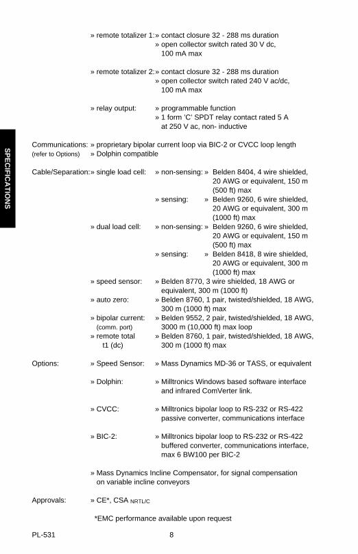
» remote totalizer 1:» contact closure 32 - 288 ms duration» open collector switch rated 30 V dc, 100 mA max
» remote totalizer 2:» contact closure 32 - 288 ms duration» open collector switch rated 240 V ac/dc, 100 mA max
» relay output: » programmable function» 1 form ’C’ SPDT relay contact rated 5 A at 250 V ac, non- inductive
Communications: » proprietary bipolar current loop via BIC-2 or CVCC loop length(refer to Options) » Dolphin compatible
Cable/Separation:» single load cell: » non-sensing: » Belden 8404, 4 wire shielded, 20 AWG or equivalent, 150 m(500 ft) max
» sensing: » Belden 9260, 6 wire shielded, 20 AWG or equivalent, 300 m(1000 ft) max
» dual load cell: » non-sensing: » Belden 9260, 6 wire shielded, 20 AWG or equivalent, 150 m(500 ft) max
» sensing: » Belden 8418, 8 wire shielded, 20 AWG or equivalent, 300 m(1000 ft) max
» speed sensor: » Belden 8770, 3 wire shielded, 18 AWG or equivalent, 300 m (1000 ft)
» auto zero: » Belden 8760, 1 pair, twisted/shielded, 18 AWG, 300 m (1000 ft) max
» bipolar current: » Belden 9552, 2 pair, twisted/shielded, 18 AWG, (comm. port) 3000 m (10,000 ft) max loop» remote total » Belden 8760, 1 pair, twisted/shielded, 18 AWG, t1 (dc) 300 m (1000 ft) max
Options: » Speed Sensor: » Mass Dynamics MD-36 or TASS, or equivalent
» Dolphin: » Milltronics Windows based software interface and infrared ComVerter link.
» CVCC: » Milltronics bipolar loop to RS-232 or RS-422 passive converter, communications interface
» BIC-2: » Milltronics bipolar loop to RS-232 or RS-422 buffered converter, communications interface, max 6 BW100 per BIC-2
» Mass Dynamics Incline Compensator, for signal compensation on variable incline conveyors
Approvals: » CE*, CSA NRTL/C
*EMC performance available upon request
SP
EC
IFIC
AT
ION
S
PL-531 8

INSTALLATION
Installation shall only be performed by qualified personneland in accordance with local governing regulations.
This product is susceptible to electrostatic shock. Follow proper grounding procedures.
DIMENSIONS
Non metallic enclosure does not provide grounding between connections. Use grounding type bushings and jumpers.
138 mm(5.4")
sealed enclosure
270 mm(10.6")
74 mm(2.9")
255 mm(10")
integral junction box(cover removed) with terminal block andvoltage selection switch
69 mm(2.7")
mounting hole6.4 mm (1/4") Ø 5 mm
(0.19")
Conduit entry area. Recommend drilling the enclosure with a hole saw andthe use of suitable cable glands to maintain ingress rating.
INS
TA
LLAT
ION
PL-531 9

INTERCONNECTION
Wiring may be run via common conduit. However these may not be run in thesame conduit as high voltage contact or power wiring.
SYSTEM DIAGRAM
Typical system capability. Not all components or their maximum quantity may be required.
ACCUMASS BW100
Mass Dynamics belt scale, seeSpecifications
customer’s remotetotalizing device
customerdevice
customer alarm, orcontrol device
mA output
relay output
speed sensor, optional,see Specifications
Milltronics BIC-2
remote totalizer
bipolar current loop
(Milltronics communications)
INS
TA
LLAT
ION
PL-531 10

TERMINAL BLOCK LAYOUT
ac supply
dc supply
All field wiring must have insulation suitable for at least 250 V.
dc terminals shall be supplied from an SELV source in accordancewith IEC-1010-1 Annex H.
INS
TA
LLAT
ION
PL-531 11

LOAD CELL - SINGLE
* Where separation between the BW100 and belt scale exceeds 150 m (500 ft) :
» remove the jumpers BW100 TB1 – 17/18 and TB1 19/20
» run additional conductors from :
» BW100 TB1 – 18 to scale ‘– EXC’» BW100 TB1 – 19 to scale ‘+ EXC’
Belt Scale
customer junction box
INS
TA
LLAT
ION
PL-531 12

LOAD CELL - DUAL
* Where separation between the BW100 and belt scale exceeds 150 m (500 ft) :
» remove the jumpers BW100 TB1 – 17/18 and TB1 19/20
» run additional conductors from :
» BW100 TB1 – 18 to scale ‘– EXC’» BW100 TB1 – 19 to scale ‘+ EXC’
Belt Scale
‘A’ loadcells ‘B’
customerjunction box
INS
TA
LLAT
ION
PL-531 13

SPEED SENSOR
Connect the BW100 TB1 – 7 to the MD - 36A speed sensor terminal:‘2’ for clockwise speed sensor shaft rotation‘3’ for counter-clockwise speed sensor shaft rotation.
MD - 36A shaft rotation is viewed from the front cover side of the MD - 36A enclosure.
If a speed sensor is not used, a jumper must be connected across the BW100TB1 – 5 / 6. If a speed sensor is used, insure that the jumper is removed.
Input device in the form of open collector transistor or dry contact across TB1 – 6 / 7 will also serve as a suitable speed signal.
MD - 36Aspeed sensor
OR TASS speed sensor
INS
TA
LLAT
ION
PL-531 14

AUTO ZERO
REMOTE TOTALIZER 1
ANALOG OUTPUT
supplymaximum 30V dc, 100 mA
remotetotalizer
to customer instrumentation
isolated mA output, 750 Ω maximum load ac models only
mA output on dc models is not isolated
prefeed activated dry contact
INS
TA
LLAT
ION
PL-531 15
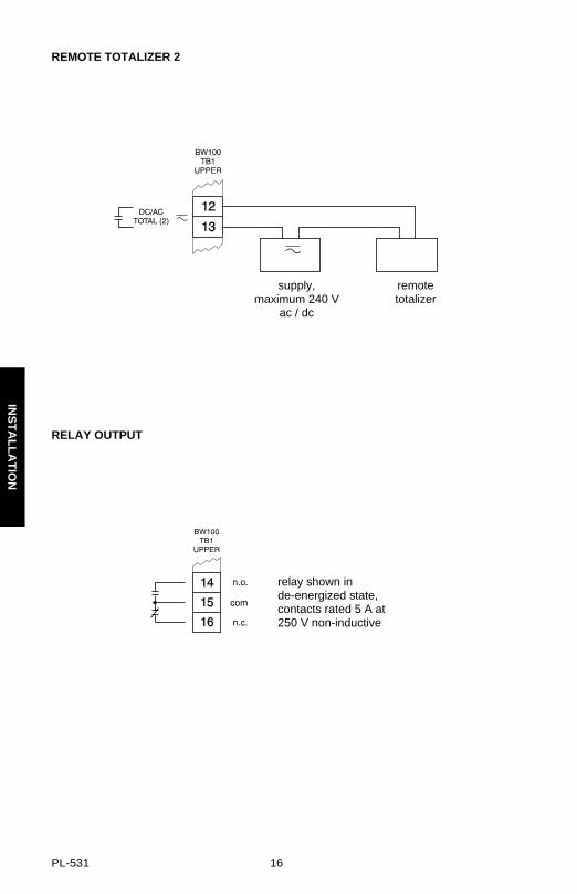
REMOTE TOTALIZER 2
RELAY OUTPUT
supply,maximum 240 V
ac / dc
remotetotalizer
relay shown inde-energized state,contacts rated 5 A at250 V non-inductive
INS
TA
LLAT
ION
PL-531 16

COMMUNICATION
CVCC
BIC-2
Connect shield at one device only, e.g. BW100 TB1 – 21.
Maximum loop length 3000 m (10,000 ft).
INS
TA
LLAT
ION
PL-531 17

POWER CONNECTIONS
AC POWER
The equipment must be protected by a 15 A fuse or a circuit breaker in the building installation.
A circuit breaker or switch in the building installation, marked as the disconnect switch, shall be in close proximity to
the equipment and within easy reach of the operator.
DC POWER
12 V dc Model
10 - 15 V dc 18 - 30 V dc
24 V dc Model
97/07/07
dc terminals shall be supplied from an SELV source in accordancewith IEC-1010-1 Annex H.
dc model indicated on lid nameplate.
INS
TA
LLAT
ION
PL-531 18

COMVERTER
Optional Dolphin Interface
Refer to Dolphin instruction manual for interconnection details.
UNITS STICKER
Remove the appropriate ‘units’ sticker from the sheet supplied, and affix to your BW100 as shown.
ACCUMASS BW100ComVerter
INS
TA
LLAT
ION
PL-531 19

INS
TA
LLAT
ION
PL-531 20

START UP
For successful start up, insure that all related system components such as beltscale and speed sensor are properly installed and connected.
ORIENTATION
Display and Keypad
The BW100 operates under two modes: ‘run’ and ‘program’. When the unit is initially powered, it starts in the program mode.
If the program mode is idle, it reverts to the run mode after 10 minutes.
LCD
Keypad
balance switch ,SW2
balance potentiometer, P1
ST
AR
T U
P
PL-531 21

Program Mode
LCD
KeyPad
MANEUVERING
To Select a Parameter:
if not in the program mode
if in the program mode
scrolldown
scroll up
access run mode
alternates programmode between‘select parameter’and ‘change value’functions
parameter value
programmode
status icon,refer to
Run Mode
parameternumber
‘change value’accessed
from therun mode
ST
AR
T U
P
PL-531 22

Speed Scroll
To speed scroll up or down press the up or down key and hold, then press the enterkey and hold. Release to stop.
To Change a Parameter Value :
Security Must Be Disabled
Must Be Pressed to Save Change!
OR
select parameter,
e.g. P005 = 1
save and return to selectparameter function,
e.g. P005 = 3
increase or decreaseto the desired value.
if no response,security not disabled
initiate change function
ST
AR
T U
P
PL-531 23

Express :
Parameterto jump back to P005
orValue
to jump to the factory setting
To Access Run Mode :
jump back to P005
e.g. P999
exit and return to run mode
e.g. from the programmode, P005S
TA
RT
UP
PL-531 24
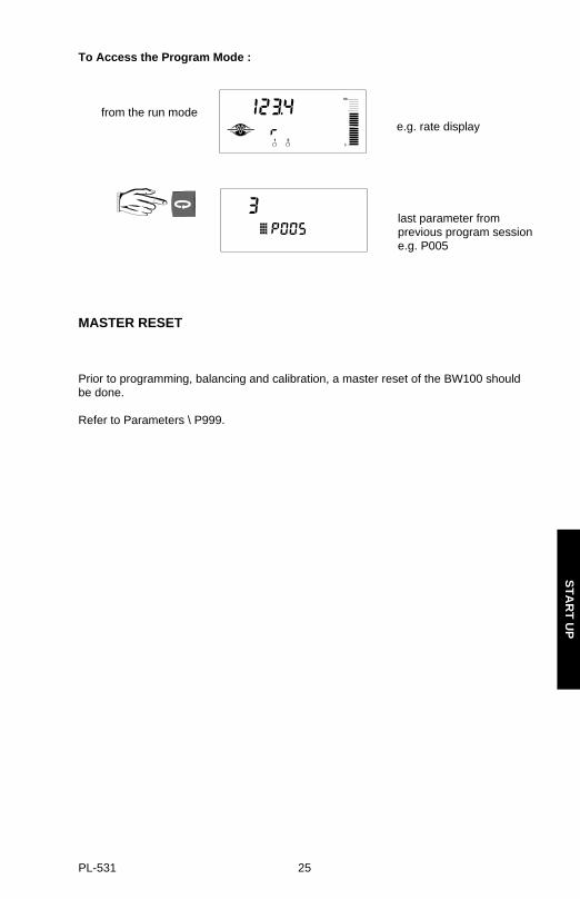
To Access the Program Mode :
from the run mode
MASTER RESET
Prior to programming, balancing and calibration, a master reset of the BW100 shouldbe done.
Refer to Parameters \ P999.
e.g. rate display
last parameter fromprevious program sessione.g. P005
ST
AR
T U
P
PL-531 25

BALANCE
If you are operating a dual load cell belt scale, it is recommended that the load cellsbe balanced electronically prior to initial programming and calibration, or after either orboth load cells have been reinstalled or replaced.
Unbalanced load cells adversely affect the performance of your belt conveyor weighing system.
With the conveyor stopped and locked out, lift the belt off the weighing idlers.
96/07/07
test weight bar
Belt Travel
typical dual load cell scale
ST
AR
T U
P
PL-531 26

Place the BW100 into the program mode at P291.
Remove the test weight, insure that the BW100 SW2 is in ‘close’ position and that P1is left as set.
Performing a balance procedure requires a subsequent zero and span recalibration.
‘A’‘B’
test weight
test weight on load cell ‘A’ side
enter and auto advance to P295
‘close’
SW2
enter and auto advance to P293,leave SW2 open
P1
adjust until## = 0 ± 5
‘A’‘B’
test weight
test weight on load cell ‘B’ side
enter and auto advance to P292,open SW2
‘close’
SW2
select P291 ensure SW2is closed
SW2
‘open’
enter and auto advance to P294,close SW2
SW2
‘open’
ST
AR
T U
P
PL-531 27
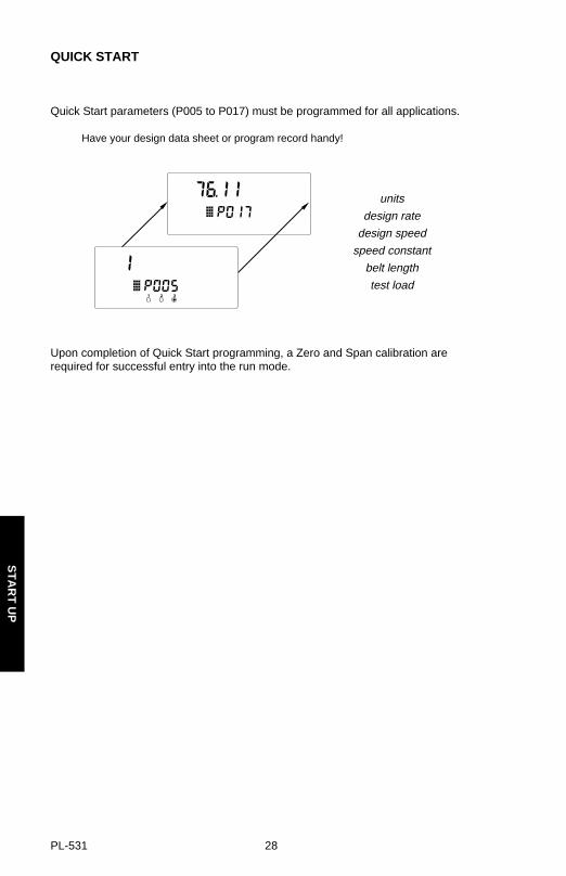
QUICK START
Quick Start parameters (P005 to P017) must be programmed for all applications.
Have your design data sheet or program record handy!
Upon completion of Quick Start programming, a Zero and Span calibration arerequired for successful entry into the run mode.
units
design rate
design speed
speed constant
belt length
test load
ST
AR
T U
P
PL-531 28
START UP
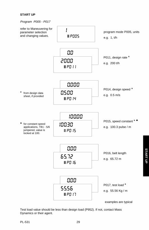
Program P005 - P017
refer to Maneuvering for parameter selection and changing values.
* from design datasheet, if provided
for constant speedapplications, TB1 - 5/6jumpered, value is locked at 100.
Test load value should be less than design load (P952). If not, contact MassDynamics or their agent.
examples are typical
program mode P005, units
e.g. 1, t/h
P014, design speed *
e.g. 0.5 m/s
P015, speed constant *
e.g. 100.3 pulse / m
P016, belt length
e.g. 65.72 m
P017, test load *
e.g. 55.56 Kg / m
P011, design rate *
e.g. 200 t/h
ST
AR
T U
P
PL-531 29

Calibration Note
The duration of Zero and Span Calibration is dependent upon speed (P014), length(P016) and revolutions (P360) of belt.
To cancel a Zero or Span calibration in progress,
and return to the run mode.
ST
AR
T U
P
PL-531 30

Zero Calibration
Run the conveyor for several minutes to warm up the belt and insure that it is empty. Test weights are not used during a zero calibration.
97/07/07
initial zero count
zero calculation,frequency count displayed
zero deviation calculated,
initial deviation = 0
zero deviation accepted,span required
zero calibration required
zero deviation accepted,initial zero count = ###Record this value forfuture reference
ST
AR
T U
P
PL-531 31

Span Calibration
Run the conveyor until the belt is empty and stop it. Suspend the test weight from thescale per its instruction manual. Run the conveyor belt empty.
Remove the test weight when the Span calibration is complete.
Run
97/07/07
span calculation,frequency count displayed
span deviation calculated
initial deviation = 0
span deviation acceptedinitial span count = ####Record this value forfuture reference
successful entry into run,display rate
initial span count
ST
AR
T U
P
PL-531 32
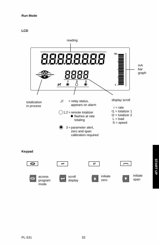
Run Mode
LCD
Keypad
initiatespan
initiatezero
access program mode
scrolldisplay
reading
mAbargraph
display scroll
r = ratet1 = totalizer 1t2 = totalizer 2 L = load S = speed
= relay status,appears on alarm
1,2 = remote totalizerflashes at ratetotaling
3 = parameter alert,zero and span calibration required
totalizationin process
ST
AR
T U
P
PL-531 33

ST
AR
T U
P
PL-531 34

RECALIBRATION
BELT SPEED COMPENSATION
In order to achieve optimum accuracy in the rate computation, the belt speeddisplayed must equal that of the actual belt speed. As the speeds are likely to differ, abelt speed compensation should be performed.
Run the conveyor with the belt empty.
View the belt speed.
Stop the conveyor and measure a length of the belt; marking the forward end (starttime) and the back end (stop time). Use the belt scale as the stationary reference.
Run the belt and measure the time for the belt length to pass over the scale.
speed = belt length m or ft time s min
Refer to maneuvering for parameter selection and value change.
If the BW100 constant speed input (TB1-5/6) is jumpered, the design speed (P014) isautomatically adjusted.
If the a speed sensor is connected, the speed constant (P015) is automaticallyadjusted.
The display speed (used in the rate computation) now equals the actual speed.
Record the new value in Appendices\Program Record.
97/07/07
run mode \ speed display,e.g. 0.750 m/s
program mode – assumed speed
e.g. 0.75 m/s
enter calculated speed
e.g. 0.8 m/s
jumps to P014 or P015showing new value
with conveyorrunning empty
RE
CA
LIBR
AT
ION
PL-531 35

MATERIAL TESTS
Material tests are performed to verify the accuracy of the of the span calibration. If thematerial tests indicate a repeatable deviation exists, a manual span adjust (P019) isthen performed. This procedure automatically alters the span calibration and adjuststhe test load (P17) value, yielding more accurate span recalibrations.
Test weights are NOT used during material tests.
» Run the belt empty.
» Perform a zero calibration.
» Put the BW100 into run mode
» Record the BW100 total as the start value _ _ _ _ _ _
» Run material at a minimum of 50% of design rate over the belt scale for a minimum of 5 minutes.
» Stop the material feed and run the conveyor empty.
» Record the BW100 total as the stop value _ _ _ _ _ _
» Subtract the start value from the stop value to determine the BW100 total
» Weigh the material sample if not already known.
BW100 total = _ _ _ _ _ _ material sample weight = _ _ _ _ _ _
» Calculate the span adjust value:% span adjust = BW100 total - material sample weight x 100
material sample weight
start total
stop total
scale
scale
RE
CA
LIBR
AT
ION
PL-531 36

If the span adjust value is within the accuracy requirements of the weighing system,the material test was successful and normal operation can be resumed.
If the span adjust value is not acceptable, repeat the material test to verifyrepeatability. If the result of the second material test differs considerably, consultMass Dynamics or their agent.
If the span adjust values are significant and repeatable, perform a manual span adjust:
refer to maneuvering for parameter selection and value change
Verify the results of the span adjust by material test or return to normal operation.
DESIGN CHANGES
Where parameters have been changed with a resultant impact on the calibration or donot take effect until a recalibration is done, the parameter warning icon is displayed. Inorder to clear the icon, perform a zero and span recalibration after the reprogrammingsession is complete.
If significant changes have been made, an initial zero (P377) and/or initial span(P388) may be required.
program mode, P019
enter % span adjust,
e.g. 0.05
jumps to P017 adjustedtest load,
e.g. 97.95
if % span adjust isnegative, be sureto enter asnegative value
RE
CA
LIBR
AT
ION
PL-531 37

RECALIBRATION
In order to maintain the accuracy of the weighing system, periodic zero and spanrecalibrations are required. Recalibration requirements are highly dependent upon theseverity of the application. Perform frequent checks initially, then as time andexperience dictate, the frequency of these checks may be reduced. Record deviationsfor reference.
Routine Zero
Run the conveyor empty for several minutes to warm up the belt and insure that it isempty. Test weights are not used during a zero calibration.
From the run mode
E3 is an indication that the mechanical system is errant. The use of P377, initial zero, should be used judiciously and only after a thorough
mechanical investigation has been exercised.
The cause of the increased deviation must be found and rectified. A zero recalibrationas previously described can then be retried.
If the operator deems this deviation to be acceptable, set P377 to 1 to invoke an initialzero calibration. Further deviation limits are now based on this new initial zero.
97/07/07
zero calculation,load value displayed
zero deviation calculated
accept deviation
new zero count = ####
return to run mode
initiate zero calibration
current zero count = ####
RE
CA
LIBR
AT
ION
PL-531 38

Initial Zero
An initial zero can be performed if deemed as a proper response to E3 message.
Refer to maneuvering for parameter selection and value change.
97/07/07
invoke initial zero,
enter ‘1’
current zero count
zero calculation
frequency count displayed
return to run mode
zero deviation accepted
initial zero count = ####
select P377
zero deviation
RE
CA
LIBR
AT
ION
PL-531 39

Direct Zero
Direct zero entry (P367) is intended for use when replacing software orhardware, and it is not convenient to perform an initial zero at that time.
A record of the last zero count is required.
Refer to maneuvering for parameter selection and value change.
current zero count
enter previously recordedzero count
new zero count accepted
RE
CA
LIBR
AT
ION
PL-531 40
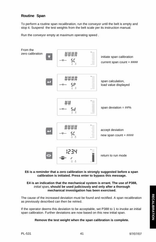
Routine Span
To perform a routine span recalibration, run the conveyor until the belt is empty andstop it. Suspend the test weights from the belt scale per its instruction manual.
Run the conveyor empty at maximum operating speed .
From thezero calibration
E6 is a reminder that a zero calibration is strongly suggested before a span calibration is initiated. Press enter to bypass this message.
E4 is an indication that the mechanical system is errant. The use of P388,initial span, should be used judiciously and only after a thorough
mechanical investigation has been exercised.
The cause of the increased deviation must be found and rectified. A span recalibrationas previously described can then be retried.
If the operator deems this deviation to be acceptable, set P388 to 1 to invoke an initialspan calibration. Further deviations are now based on this new initial span.
Remove the test weight when the span calibration is complete.
97/07/07
span calculation,load value displayed
span deviation = ##%
accept deviation
new span count = ####
return to run mode
initiate span calibration
current span count = ####
RE
CA
LIBR
AT
ION
PL-531 41

Initial Span
An initial span can be perform if deemed as a proper response to E4 message.
Refer to maneuvering for parameter selection and value change.
invoke initial span
current span count = ####
span calculation,
frequency count displayed
return to run mode
zero deviation accepted
initial zero count = ####
select P388
span deviation = ##
RE
CA
LIBR
AT
ION
PL-531 42

Direct Span
Direct span entry (P368) is intended for use when replacing software or hardware, and it is not convenient to perform
an initial span at that time.
A record of the last span count is required.
Refer to maneuvering for parameter selection and value change.
new span count accepted
enter previously recordedspan count
current span count
RE
CA
LIBR
AT
ION
PL-531 43

Factoring
In order to calculate the value of a new or unknown test weight to the current span,the factoring procedure is used.
For optimum accuracy in the factoring results, a routine zero calibration is recommended.
Refer to Maneuvering for parameter selection and value change.
With the conveyor stopped and the belt empty:
enter
initiated Factoring,current test load value
e.g. 76.11 kg / m
dynamic test load value
e.g. 76.03 kg / m
hang new test weight ontobelt scale, then run theconveyor empty
return to run mode
P359 selected
jumps to P017,new test load value
e.g. 76.03 kg / m
RE
CA
LIBR
AT
ION
PL-531 44

Linearization
Conveyor applications where the belt scale is poorly located, or where there is a highdegree of variation in belt tension, typically cause the belt scale to report loadnon-linearly. The BW100 provides a linearizing function (P390 - P396) in order tocorrect for the deficiency in the weighing system and to provide an accurate report ofthe actual process.
To verify that the cause of the non-linearity is not mechanical:
» run the conveyor belt empty and stop it.
» Suspend various test weights to the scale to verify mechanical linearity. If the load reported by the BW100 at these tests is non-linear, a mechanical problem is indicated. Refer to the belt scale manual in order to resolve the non-linearity by improved installation or repair.
If it is determined that the non-linearity is due to the weighing application, and not theactual belt scale, apply linearization by performing the following:
» zero calibration
» span calibration at 90 to 100% of design rate
» material tests at 90 to 100% of design rate
» manual span adjust if required
» material tests at 1 to 3 intermediary flow rates where compensation is required.
Compensation points must be at least 10% of the design load apart.
E8 message occurs if a point is less than 10% of full scale or if points are less than 10% apart.
» calculate the percentage compensation for each flow rate tested.
% compensation = actual weight - totalized weight x 100totalized weight
where: actual weight = material testtotalized weight = BW100 total
97/07/07
RE
CA
LIBR
AT
ION
PL-531 45
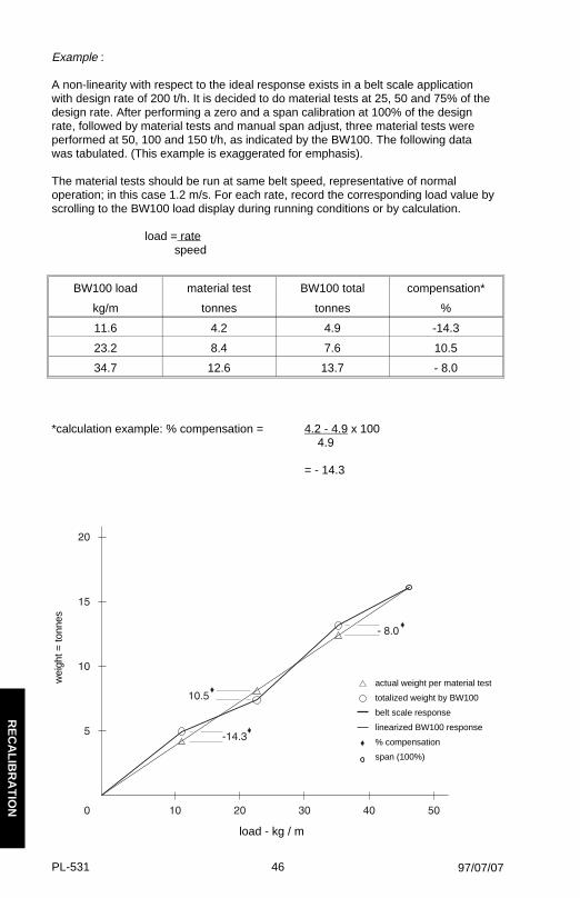
Example :
A non-linearity with respect to the ideal response exists in a belt scale application with design rate of 200 t/h. It is decided to do material tests at 25, 50 and 75% of thedesign rate. After performing a zero and a span calibration at 100% of the design rate, followed by material tests and manual span adjust, three material tests wereperformed at 50, 100 and 150 t/h, as indicated by the BW100. The following data was tabulated. (This example is exaggerated for emphasis).
The material tests should be run at same belt speed, representative of normaloperation; in this case 1.2 m/s. For each rate, record the corresponding load value byscrolling to the BW100 load display during running conditions or by calculation.
load = rate speed
*calculation example: % compensation = 4.2 - 4.9 x 100 4.9
= - 14.3
97/07/07
BW100 load material test BW100 total compensation*
kg/m tonnes tonnes %
11.6 4.2 4.9 -14.3
23.2 8.4 7.6 10.5
34.7 12.6 13.7 - 8.0
load - kg / m
actual weight per material test
totalized weight by BW100
belt scale response
linearized BW100 response
% compensation
span (100%)
wei
ght =
tonn
es
RE
CA
LIBR
AT
ION
PL-531 46

Program the BW100 as follows: P390 = 1P391 = 11.6P392 = - 14.3P393 = 23.2P394 = 10.5P395 = 34.7P396 = - 8
Often only one point of compensation is required, usually at a low load value. In theprior example, if compensation was only required at 11.6 kg/m, the programmingcould be as follows. Compensation is optimized by establishing the next load valuethat agrees with the material test, hence where compensation is zero and entering itas the next compensation point.
P390 = 1P391 = 11.6P392 = - 14.3P393 = 23.2P394 = 0P395 = 34.7P396 = 0
actual weight per material test
totalized weight by BW100
belt scale response
linearized BW100 response
% compensation
span (100%)
load - kg / m
wei
ght =
tonn
es
RE
CA
LIBR
AT
ION
PL-531 47

RE
CA
LIBR
AT
ION
PL-531 48

OPERATION
LOAD SENSINGIn order for the BW100 to calculate rate and hence totalize material flow along the beltconveyor, a load signal representative of weight of material on the belt is required.The load signal is provided by the belt scale. The BW100 is compatible with beltscales fitted with one or two strain gauge type load cells.
Refer to Specifications and Installation\Load Cell for belt scale requirements and connection.
SPEED SENSINGIn order for the BW100 to calculate rate and hence totalize material flow along the belt conveyor, a speed signal representative of belt speed is required. In constantspeed applications (no speed sensor), the BW100 can be programmed to provide an internal speed signal. This is achieved by entering the design speed (P014) andproviding a jumper across speed input terminals (TB1-5/6). Speed constant (P015)defaults to 100.
For optimum accuracy of the weighing system, both constant and variable speedapplications, a speed sensor is required. Again, the design speed and speedconstants need to be programmed, however the jumper across the speed input has tobe removed and the speed sensor connected.
Refer to Specifications and Installation\Speed Sensor for speed sensor requirementsand connection.
MODES OF OPERATIONRun is the normal or reference mode of operation. It continuously processes the loadsignal from the belt scale to produce internal load and rate signals, which are in turnused as the basis for totalization, mA output and relay control. The run display isprogrammed (P081) to scroll through rate, totalization, load and speed; eithermanually by pressing the enter key, or automatically. A bar graph is continuouslydisplayed. It is proportional to the analog output as programmed (see Analog Output).
From the run mode, access to the program mode, and zero and span calibration is made.
The program mode allows viewing and, with security permission (P000), changingparameter values. During program, run mode functions are still active, i.e.: rate, relay, analog output and totalization. Error interrupts are suppressed and the bargraph is disabled.
If the program mode is left idle for a period of ten minutes, it automatically reverts tothe run mode.
97/07/07
OP
ER
AT
ION
PL-531 49

DAMPINGDamping (P080) provides control over the speed at which the displayed readings andoutput functions respond to changes in their respective input function; load, speedand the internal rate signals. Changes in the displayed rate of material flow, materialloading and belt speed are controlled by the damping. Relay alarm functions based oninput functions of flow, load and speed, respond to the damped value.
If the specific mA output damping parameter (P220) is enabled (value other than 0),then the damping (P080) as it pertains to the mA function is overridden, and theoutput value and bar graph respond independently at the specified mA outputdamping rate (P220).
ANALOG OUTPUTThe BW100 provides one isolated analog output. The output can be assigned (P201)to represent rate, load or speed. The output range can be set to 0 - 20 mA or 4 - 20mA (P200). The 0 or 4 mA value corresponds to empty or zero condition, whereas the20 mA value corresponds to the associated design value: rate (P011), load (P952) orspeed (P014). The analog output can be limited for over range levels of 0 mAminimum and 22 mA maximum (P212 and P213 respectively). The output 4 and 20mA levels can also be trimmed (P214 and 215 respectively) to agree with amilliammeter or other external mA input device.
The BW100 LCD provides a bar graph as a function of analog output. It displays themA value as percentage of the mA range.
The mA output value can be tested using parameter P911. Refer to ParameterDescription\P911.
97/07/07
OP
ER
AT
ION
PL-531 50

RELAY OUTPUTThe BW100 offers one single pole double throw (SPDT) relay that can be assigned(P100) to one of the following alarm functions:
» rate: relay alarms on high and/or low material flow rate.
» auto zero: relay alarms when an attempted auto zero calibration reports an out of range condition (E9).
» speed: relay alarms on high and/or low belt speed.
» load: relay alarms on high and or low belt load.
» error: relay alarms on any error condition as it is reported. Refer to Appendices \ Troubleshooting.
Except for alarm on ‘auto zero’ and ‘error’, the high and low alarm setpoints (P101 andP102 respectively) are required and must be entered in the appropriate units.
The on / off actuation at both setpoints is buffered by the damping (P080) and theprogrammable dead band (P117), to prevent relay chatter due to fluctuations. Therelay is normally energized; i.e. the normally closed (n.c.) contact held open. Upon analarm condition, the relay is de-energized and the alarm icon on the BW100 displayappears. Once in alarm, the relay and icon remain in alarm status until the alarmcondition is removed.
Example:
P014 = 2m/s, design speedP100 = 3, belt speedP101 = 100% (2m/s)
97/07/07
high100%
low20%
actual ‘off ’22%
actual ‘on’20%
alarm ‘on’ is with relay de-energized
OP
ER
AT
ION
PL-531 51

TOTALIZATIONThe totalization function is based on the internal rate (mass per unit time) signalproportional to belt speed and load on the associated belt scale. It is not affected by the damping function (P080). The rate signal is sampled several times a second to accurately count the mass of material conveyed. The count is held in the mastertotalizer used to increment the internal totalizers and to produce a pulse signal for the remote totalizers.
The BW100 provides four separate totalizer functions: internal totalizer 1, internaltotalizer 2, remote totalizer 1 and remote totalizer 2.
To avoid totalizing material at low flow rates, the totalizer drop out limit (P619) is set toa percentage of the design rate. Below this limit, totalization stops. When material flowreturns to a rate above the drop out limit, totalization resumes.
Totalizer resolution or count value is set by the respective control parameters, P631 -P639. If the resolution selected causes the totalizer to lag behind the count rate, anE2 error is displayed after making the parameter entry. The error is rectified byselecting a greater resolution value.
e.g.: internal totalizer 1
given: P005 = 1 (t/h)P631 = 5
then: totalizer count increments by 10 for each 10 metric tonnes registered
external totalizer 1
given: P005 = 1 (t/h)P638 = 5
then: contact closure occurs once for every 10 metric tonnes registered
For remote totalization, the contact closure duration is set by the respective controlparameters, P643 and P644. The value is automatically calculated upon entry of thedesign rate (P011) and remote totalizer parameters (P638 and P639), so that theduration of contact closure allows the relay response to track the total up to the designrate. The value can be changed to suit specific contact closure requirements, such asin the case of programmable logic controllers. If an E2 error is displayed, P638 orP639 has to be increased.
The totalizers are reset through the master reset (P999), the totalizer reset (P648) orthrough the keypad.
» master reset: the reset of all totalizer functions is included in the master reset.
» totalizer reset: totalizer reset can be used to resets internal totalizers 1 and 2, or totalizer 2 independently.
» keypad: pressing simultaneously while in the run mode resets internal totalizer 1, as well as the internal counts for both remote totalizers.
Placing the internal totalizers on to the display scroll of the run mode is controlled bythe totalizer display parameter (P647); displaying either one or both totalizers.
97/07/07
OP
ER
AT
ION
PL-531 52
AUTO ZEROThe Auto Zero function allows a zero calibration to be initiated automatically under thefollowing conditions.
- the auto zero input (TB1-9/10) is in a closed state; jumper or remote switch
- the load is less than 2% of the design load
If the resulting zero deviation is less than an accumulated 2% from the last operatorinitiated zero, the auto zero is accepted.
If the deviation is greater than an accumulated 2%, an E9 error is displayed and therelay, if so programmed, goes into alarm (refer to Operation\Relay Output). The E9error is cleared after five seconds.
If material feed resumes during an auto zero function, the totalizing function is maintained.
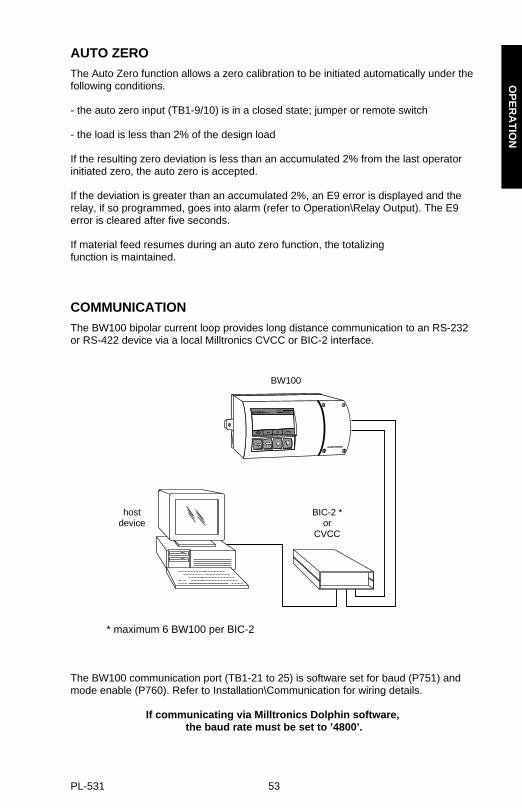
COMMUNICATIONThe BW100 bipolar current loop provides long distance communication to an RS-232or RS-422 device via a local Milltronics CVCC or BIC-2 interface.
* maximum 6 BW100 per BIC-2
The BW100 communication port (TB1-21 to 25) is software set for baud (P751) andmode enable (P760). Refer to Installation\Communication for wiring details.
If communicating via Milltronics Dolphin software, the baud rate must be set to ’4800’.
BW100
hostdevice
BIC-2 *or
CVCC
OP
ER
AT
ION
PL-531 53

PROTOCOLProtocol refers to the format, sequence and value of the data fields used incommunication messages. Each data field of a BW100 message contains one ormore bytes of ASCII binary code.
Each byte contains:
» 8 data bits» no parity bit » 1 stop bit
DATA FIELD DESCRIPTIONS
The following data fields are used.
som
BW100 start of message, ASCII character = STX (Hex Value = 02).
DEVICE
Identifies the BW100 to which the message applies. The device is a 2 characternumber that equals the Unit I.D. code, (P761). ASCII characters = 00 to 15.
MT
Identifies the 2 character message type transmitted, ASCII characters:
50 = material flow rate51 = material load52 = belt speed53 = totalizer 1, internal54 = totalizer 2, internal
READING
Contains the measurement value in the engineering units of measure selected during BW100 programming. The number of bytes in this data field varies dependentupon the reading value. Up to 8 ASCII characters including the decimal point may be transmitted.
UNITS
Three ASCII characters identify the totalizer engineering units (MT=53 and MT=54).The first character is always a space. The remaining characters may be:
t = tonnesT = tonsLT = long tonskg = Kilogramslb = pounds
eomBW100 end of message, ASCII character = CR (Hex Value = 0D).
OP
ER
AT
ION
PL-531 54

MESSAGE REQUESTS
Message requests must be transmitted from the host to the BW100 in the following format.
som DEVICE MT eom
Example:
Data ASCII ExampleField Character Description
som STX start of messageDEVICE 01 for BW100 # 1MT 50 material flow rate requesteom CR end of message
MESSAGE RESPONSES
The BW100 response to a flow rate (MT=50) load (MT=51) or speed (MT=52)message request is in the following format.
som DEVICE MT READING eom
Example:
Data ASCII ExampleField Character Description
som STX start of messageDEVICE 00 from BW100 # 0MT 50 material flow rate responseREADING 392.5 is 392.5eom CR end of message
The response to a material total (MT=53) message request is in the following format.
som DEVICE MT READING UNITS eom
Example:
Data ASCII ExampleField Character Description
som STX start of messageDEVICE 01 from BW100 # 1MT 53 material total responseREADING 129.2 is 129.2UNITS t metric tonnes eom CR end of message
OP
ER
AT
ION
PL-531 55

OP
ER
AT
ION
PL-531 56

PARAMETER DESCRIPTION
P000 lock
Locks out the programming ’change value’ function such that the values of P001 through P999 cannot be changed. This however does not prevent the ’select’ function from use; i.e. for viewing values. Programming is locked out if the value of P000 is other than 1954.
entry: 1954 = unlocked1954 = locked
Ouick Start, P005 to P017
’Ouick Start ’ is the minimum parameter programming required before attempting a calibration and successful entry into the run mode.
P005 units
Determines the units for programming and measurement.
entry: 1 = t/h, tonnes per hour2 = kg/h, kilograms per hour3 = LT/h, long tons per hour4 = T/h, short tons per hour5 = lb/h, pounds per hour
Changing this parameter does not affect the rate (P011), belt speed (P014) or belt length (P016) parameters. These parameters should be re-entered forconformity in units.
t = 1000 kgLT = 2240 lb.T = 2000 lb.
P011 design rate
Specifies the design rate of material flow for the belt scale.
enter the design rate from the supplied design data sheet
PA
RA
ME
TE
R D
ES
C.
PL-531 57

P014 design speed
Specifies the design speed for the conveyor belt.
Speed units are: metre/s if P005 = 1 or 2feet/min if P005 = 3, 4 or 5
P015 speed constant
This value multiplied with the speed sensor frequency, calculates the actual belt speed.
entry: If speed input is wired for constant speed (TB1 5/6 jumpered), value defaults to ’100’.
enter the speed constant = from the supplied design data sheet
or
= speed sensor pulses per revolution* pulley circumference (m or ft)/ revolution
* refer to speed sensor nameplate or consult Mass Dynamics or their agent
P016 belt length
The length of the conveyor belt (one belt revolution).
Length units are: metre if P005 = 1 or 2 ft if P005 = 3, 4 or 5
enter the belt length
P017 test load
The load to be referenced when performing a span.
Load units are: kg/m if P005 = 1 or 2lb/ft if P005 = 3, 4 or 5
End of ’short program’ parameters. A calibration can now be performed.
PA
RA
ME
TE
R D
ES
C.
PL-531 58

P018 speed constant adjust
This parameter allows adjustment to the speed constant (P015).
Initially, this parameter displays the dynamic speed of the belt. If the displayed speed is not equal to the actual speed, enter the actual belt speed.
For speed sensor applications, the value of P015 is automatically adjusted.
For constant speed (TB1 5/6 jumper) the value of P014 is automatically adjusted.
P019 manual span adjust
This parameter allows adjustment to the span calibration.
The adjustment value is generally determined by performing material tests. Refer to Recalibration\Material Tests.
enter the calculated adjustment
P022 minimum speed frequency
Sets the minimum frequency that the speed sensor can reliably read. Signals at low frequencies are erratic, adversely affecting the performance of the weighing system.
entry: 1 = 1 Hz2 = 2 Hz
note:at 1 Hz, it takes 1 sec before defaulting to 0 speedat 2 Hz, it takes 0.5 sec before defaulting to 0 speed
PA
RA
ME
TE
R D
ES
C.
PL-531 59

P080 damping
Sets the speed of response to which the displayed readings (rate, load and speed), and outputs (alarm and mA) react to change..
Effect of damping (P080) on mA output can be overridden by mA output damping (P220).
The greater the damping value, the slower the response.
enter damping value, range 1 - 9999
P081 display mode
Sets the display mode. Normally, the display shows rate, or the last manually selected function. If set to alternating, the display alternates between rate and totalizer (1 and/or 2, as programmed by P647).
entry: 0 = normal1 = alternating
PA
RA
ME
TE
R D
ES
C.
PL-531 60

Relay/Alarm Function, P100 - P117
These parameter are specific to the use of the relay/alarm function. Refer to Operation\Relay Output.
P100 relay set up
Sets the alarm mode for the relay.
entry: 0 = off 1 = rate2 = auto zero3 = belt speed4 = belt load5 = error
P101 high alarm
Sets the high alarm setpoint for relay functions P100 = 1, 3 or 4.
enter the value in % of full scale
P102 low alarm
Sets the low alarm setpoint for relay functions P100 = 1, 3 or 4.
enter the value in % of full scale
P117 alarm dead band
Sets the dead band to prevent relay chatter due to fluctuations at the high or low setpoint.
enter the value in % of full scale
End of relay/alarm parameters.
PA
RA
ME
TE
R D
ES
C.
PL-531 61

mA output parameters, P200 - P220
These parameters are specific to the use of the mA output. Refer to Operation \ mA Output for details.
P200 mA range
Sets the range for the mA output.
entry: 1 = 0 - 20 mA2 = 4 - 20 mA
P201 mA function
Assigns the mA output to track one of the integrator functions.
entry: 1 = rate2 = load3 = speed
P212 mA min limit
Limits the lower mA range (0 or 4 mA) to a minimum output value.
enter limit value, range 0 - 22
P213 mA max limit
Limits the upper mA range (20 mA) to a maximum output value.
enter limit value, range 0 - 22
P214 4 mA trim
Adjusts the 4 mA output level to agree with a milliammeter or other external mA input device.
enter trim value, range 0 - 9999
PA
RA
ME
TE
R D
ES
C.
PL-531 62

P215 20 mA trim
Adjusts the 20 mA output level to agree with a milliammeter or other external mA input device.
enter trim value, range 0 - 9999
P220 mA output damping
Sets the speed at which the mA output reacts to change.
The greater the damping value, the slower the response. If the value is 0, the mA output assumes the damping set in P080.
enter the damping value, range 0 - 9999
End of mA output parameters.
PA
RA
ME
TE
R D
ES
C.
PL-531 63

Load Cell Balancing Parameters, P291 - P295
These parameters are used for verifying or balancing the load cells (2) on the associated conveyor belt scale. Refer to Start Up\Balancing
for details and procedure for use of these parameters.
P291 calculator input 1
This register displays the count associated with the summation of load cell A and B signals, when balancing the A and B load cells of the associated belt scale.
P292 calculator input 2
This register displays the count associated with the load B signal, when balancing the A and B load cells of the associated belt scale.
P293 calculator input 3
This register displays the count associated with the load cell B signal, when balancing the A and B load cells of the associated belt scale.
P294 calculator input 4
This register displays the count associated with the summation of load cell A and B signals, when balancing the A and B load cells of the associated belt scale.
P295 load cell balance
Used in conjunction with balance calculator parameters (P291 - P 294), this parameter displays the adjustment required to complete the load cell balance procedure.
End of balancing parameters
PA
RA
ME
TE
R D
ES
C.
PL-531 64

P341 run time
The cumulative days that the application device has been in service. The time is recorded once daily in a non-resetable counter. Periods of less than 24 hr. are not recorded, nor accumulated.
P350 calibration security
This parameter provides additional security to the global lock (P000).
entry: 0 = view parameters, perform zero and span, no reset of totalizer 11 = same as level 0, but cannot perform span2 = same as level 0, but cannot perform zero and span
P359 factoring
Factoring is used as a method of calculating the value of the test load (P017) to a new physical test weight.
entry: 0 = idle1 = factor
Totalization is halted during the factoring procedure, and resumed only upon return to the run mode.
P360 calibration duration
Sets the number of belt revolutions to use during a zero or span calibration.
enter number of belt revolutions, range 1 - 99
P367 direct zero
This parameter allows the zero reference count to be viewed or entered directly.
Direct entry is intended for use when replacing software or hardware and it is not convenient to perform an initial zero at that time.
PA
RA
ME
TE
R D
ES
C.
PL-531 65

P368 direct span
This parameter allows the span reference count to be viewed or entered directly.
Direct entry is intended for use when replacing software or hardware and it is not convenient to perform an initial span at that time.
P370 zero limit
Sets the zero calibration deviation limit from the last initial zero. If the accumulated deviation exceeds the limit, the zero calibration is aborted (E3).
entry: 0 = ± 12.5% of initial zero1 = ± 2% of initial zero
P377 initial zero
The initial zero is the reference zero to which all subsequent operator initiated zero calibrations are compared in determining whether they have deviated beyond the zero limit (P370)
entry: 0 = idle1 = initial zero
Refer to Recalibration\Initial Zero for use of this function.
P388 initial span
The initial span is the reference to which all subsequent span calibrations are compared in determining whether they have deviated beyond 12.5% of the initial span.
entry: 0 = idle1 = initial zero
Refer to Recalibration\Initial Span for use of this function.
PA
RA
ME
TE
R D
ES
C.
PL-531 66

Linearization Parameters, P390 - P396
These parameters are used to compensate for non-linear response of the weighingsystem to the BW100. Refer to Recalibration\Linearization for details and example on
the use of these parameters.
P390 linearization
Enables or disables the linearization function.
entry: 0 = off1 = on
P391 linearizer, point 1
enter the load, in units of P017, for point 1
P392 compensation, point 1
enter the calculated compensation, in percent, for compensation point 1
P393 linearizer, point 2
enter the load, in units of P017, for point 2
P394 compensation, point 2
enter the calculated compensation, in percent, for compensation point 2
P395 linearizer, point 3
enter the load, in units of P017, for point 3
P396 compensation, point 3
enter the calculated compensation, in percent, for compensation point 3
End of Linearization Parameters.
PA
RA
ME
TE
R D
ES
C.
PL-531 67

Totalization, P619 - P648
The following parameters are specific to the use to the BW100 totalizers. Refer also to Operation\Totalization.
If the resolution (P631 - P639) selected would cause the totalizer to lag behind the count rate, a message E2
is displayed after making the entry.
Select a greater resolution value.
e.g. given: P005 = 1 (t/h)P631 = 5
then: totalizer count increments by 10 for each 10 metric tonne registered
P619 totalizer drop out
This parameter sets the limit, in percent of design rate, below which material rates are not totalized.
The value of ’0’ is reserved to allow both negative and positive totalization.
enter drop out value in % of design rate
P631 totalizer 1 resolution, internal
This parameter sets the resolution of internal totalizer 1.
entry: 1 = 0.001 (one thousandth)2 = 0.01 (one hundredth)3 = 0.1 (one tenth)4 = 1 (unit)5 = 10 (x ten)6 = 100 (x hundred)7 = 1000 (x thousand)
PA
RA
ME
TE
R D
ES
C.
PL-531 68

P632 totalizer 2 resolution, internal
This parameter sets the resolution of internal totalizer 2.
entry: 1 = 0.001 (one thousandth)2 = 0.01 (one hundredth)3 = 0.1 (one tenth)4 = 1 (unit)5 = 10 (x ten)6 = 100 (x hundred)7 = 1000 (x thousand)
P638 totalizer 1 resolution, external
This parameter sets the resolution of external totalizer 1.
entry: 1 = 0.001 (one thousandth)2 = 0.01 (one hundredth)3 = 0.1 (one tenth)4 = 1 (unit)5 = 10 (x ten)6 = 100 (x hundred)7 = 1000 (x thousand)
P639 totalizer 2 resolution, external
This parameter sets the resolution of external totalizer 2.
entry: 1 = 0.001 (one thousandth)2 = 0.01 (one hundredth)3 = 0.1 (one tenth)4 = 1 (unit)5 = 10 (x ten)6 = 100 (x hundred)7 = 1000 (x thousand)
PA
RA
ME
TE
R D
ES
C.
PL-531 69

P643 totalizer 1 contact closure, external
The value of this parameter represents a multiple of 32 ms of contact closure for remote totalizer 1. The value is automatically calculated upon entry of P1 (design rate) and P638 (totalizer 1 resolution, external) so that the duration of contact closure allows the transistor switch response to track the total, up to the design rate.
The value can be changed to suit specific contact closure requirements, such as in the case of programmable logic controllers. If a message E2 is displayed, P638 has to be increased.
entry: 1 = 32 ms 6 = 1922 = 64 7 = 2243 = 96 8 = 2564 = 128 9 = 2885 = 160
P644 totalizer 2 contact closure, external
The value of this parameter represents a multiple of 32 ms of contact closure for remote totalizer 2. The value is automatically calculated upon entry of P1 (design rate) and P639 (totalizer 2 resolution, external) so that the duration of contact closure allows the transistor switch response to track the total, up to the design rate.
The value can be changed to suit specific contact closure requirements, such as in the case of programmable logic controllers. If a message E2 is displayed, P639 has to be increased.
entry: 1 = 32 ms 6 = 1922 = 64 7 = 2243 = 96 8 = 2564 = 128 9 = 2885 = 160
PA
RA
ME
TE
R D
ES
C.
PL-531 70

P647 totalizer display
Selects the totalizer combination to be displayed, either manually through the scroll display key or automatically by control of the display mode (P081).
entry: 1 = totalizer 12 = totalizer 23 = totalizers 1 and 2
P648 totalizer reset, internal
Resets the internal totalizers.
entry: 0 = idle1 = reset totalizer 22 = reset totalizers 1 and 2
End of Totalization parameters.
PA
RA
ME
TE
R D
ES
C.
PL-531 71

Communication, P751 - P761
These parameters are specific to the use of the communication parameters. Refer also to Appendices\Communication.
P751 baud rate
Sets the baud rate for the proprietary bi-polar current loop. This baud rate is not applicable to communication via Milltronics Comverter.
entry: 300, 1200, 2400, 4800 or 9600 baud
4800 baud is required for Dolphin communications over thebi-polar current loop.
P760 communication mode
Selects the communication mode.
» bi-polar current loop: interface with the host device (PLC or computer) is made through the Milltronics BIC-2 or CVCC. Refer to Operation\Communication.
» infrared link: communication is made using the Milltronics ComVerter.
» maintenance: communication is made via the bi-polar current loop for run mode operations and infrared link for program mode operations
entry: 1 = bipolar current loop2 = infrared link3 = maintenance
P761 identification number
Sets the identification number for the unit.
enter the desired identification number, range 0 - 15
End of communication parameters.
PA
RA
ME
TE
R D
ES
C.
PL-531 72

Test and Diagnostic, P900 - P951
These parameter are used for test and diagnostic purposes.
P900 software revision
Displays the EPROM (Flash ROM) software revision level.
P901 memory
Tests the memory. Test is initiated by scrolling to the parameter or repeated by ’pressing enter’
display:PASS = normalFAIL = consult Mass Dynamics
P907 programmer interface
Tests the infrared communications link. Test is initiated by scrolling to the parameter or repeated by ’pressing enter’.
display: PASS = normal FAIL = consult Milltronics
P911 mA output value
Displays the value from the previous measurement. A test value can be entered and the displayed value is transmitted to the output. Upon returning to the run mode, the parameter assumes the actual mA output level.
infrared communication link
mirror
BW100
PA
RA
ME
TE
R D
ES
C.
PL-531 73

P940 load cell ’A’, mVin
Displays the mV signal input from the load cell. Range 0.00 - 60.00 mV.
P941 load cell ’B’, mVin
Displays the mV signal input from the load cell. Range 0.00 - 60.00 mV.
P942 V/F converter, Vin
Displays the input voltage to the voltage to frequency converter. Range 0 - 3.98 V
P943 V/F converter, fout
Displays the output frequency of the voltage to frequency converter. Range 0 - 131,072
P944 power sensor
Displays a voltage supply reference for diagnostic purposes.
P949 diagnostic errors
Enables or disables diagnostic error checking, E101 - E104
entry: 0 = disable1 = enable
Refer to Troubleshooting.
P950 zero register
Registers the number of zero calibrations that have been done since the last master reset.
97/07/07
PA
RA
ME
TE
R D
ES
C.
PL-531 74
P951 span register
Registers the number of span calibrations that have been done since the last master reset.
P952 design load
Displays the value of the design load, which corresponds to the full scale value for alarm and mA output functions. The design load is calculated, based on the design rate and design speed.
End of test and diagnostic parameters.
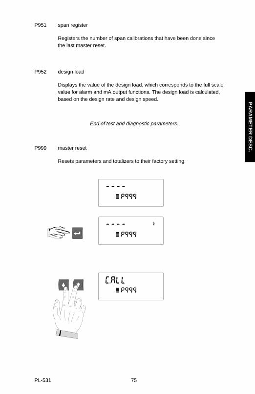
P999 master reset
Resets parameters and totalizers to their factory setting.
PA
RA
ME
TE
R D
ES
C.
PL-531 75

PA
RA
ME
TE
R D
ES
C.
PL-531 76

APPENDICES
ALPHABETICAL PARAMETER LIST
parameter number
Alarm Dead Band P117
Baud Rate P751
Belt Length P016
Calculator Input 1 P291
Calculator Input 2 P292
Calculator Input 3 P293
Calculator Input 4 P294
Calibration Duration P360
Calibration Security P350
Communication Mode P760
Compensation Point 1 P392
Compensation Point 2 P394
Compensation Point 3 P396
Damping P080
Design Rate P011
Design Speed P014
Direct Span P368
Direct Zero P367
Display Mode P081
Factoring P359
High Alarm P101
Identification Number P761
Initial Zero P377
AP
PE
ND
ICE
S
PL-531 77

Initial Span P388
Linearization P390
Linearizer Point 1 P391
Linearizer Point 2 P393
Linearizer Point 3 P395
Load Cell “A”, mV in P940
Load Cell “B”, mV in P941
Load Cell Balance P295
Lock P000
Low Alarm P102
mA Function P201
mA Output Damping P220
mA Output Value P911
mA Maximum Limit P213
mA Minimum Limit P212
mA Range P200
mA Trim, 20 P215
mA Trim, 4 P214
Manual Span Adjust P019
Master Reset P999
Memory P901
Minimum Speed Frequency P022
Power Sensor P944
Programmer Interface P907
Relay Set Up P100
Run Time P341
Software Revision Number P900
Span Register P951
Speed Constant P015
AP
PE
ND
ICE
S
PL-531 78

Speed Constant Adjust P018
Test Load P017
Totalizer 1 Closure, External P643
Totalizer 2 Closure, External P644
Totalizer 1 Resolution, External P638
Totalizer 2 Resolution, External P639
Totalizer 1 Resolution, Internal P631
Totalizer 2 Resolution, Internal P632
Totalizer Display P647
Totalizer Drop out P619
Totalizer Reset, Internal P648
Units P005
V/F Converter, V in P942
V/F Converter, f out P943
Zero Register P950
Zero Limit P370
AP
PE
ND
ICE
S
PL-531 79

TROUBLESHOOTING
message diagnosis action
E1 (program) security code required enter access code into P000
E2 (run) totalizer resolution too low increase value (P631 - P639)
E3 (run) zero out of range consider an initial zero P377, refer to Recalibration\Initial Zero
E4 (run) span out of range consider an initial span P388,refer to Recalibration\Initial Span
E5 (run) parameter not entered check parameters P005 - P017for entry
E6 (run) zero calibration required do a zero calibration
E7 (run) span calibration required do a span calibration
E8 (program) parameter value error check that value is valid
E9(run) auto zero out of range auto zero has accumulated deviation beyond 2% from last operator initial zero. If error is not caused by material on belt, then do an operator initiated zero.
E10 (run) rate or span out of range loading on belt is 300% of rated load or greater. Investigate and if no mechanical cause, check to see if re-rating the design rate is required.
E11 (run) speed greater than twice check design belt speed against the design speed actual belt speed,check speed
constant, perform speed constant adjust (P018) if necessary.
E12 (factoring) span out of range test load is either too low or beyond 100% of design load (P952). Replace test weight witha heavier or lighter weight and try factoring again.
E101 (run) load cell ’A’ check wiring
E102 (run) load cell ’B’ check wiring
AP
PE
ND
ICE
S
PL-531 80

E103 (run) load cell check wiring
E104 (run) memory checksum contact Mass Dynamics or their distributor
OF no speed signal check speed circuit or run conveyor
» Error messages are cleared when the condition is remedied.
» Run mode errors are suppressed during program mode, zero or span calibration.
» Zero and span errors are cleared when zero or span is initiated. Errors that happen during the calibration require re-starting the procedure.
» Program errors are cleared when any key is pressed.
» The messages E101 through E104 can be turned off (P949).
» The load cell errors are detected by certain conditions where it is apparent that the load cell is not functioning or incorrectly wired. It is not a conclusive test, since even with incorrect wiring, the resulting input from the load cell may be within a valid range. A
PP
EN
DIC
ES
PL-531 81

MAINTENANCE
The BW100 requires no maintenance.
The external surface of the enclosure may be cleaned using a vacuum cleaner and a clean dry paint brush. The display window should be cleaned with a moistnon-abrasive cloth.
It is a good idea to check the associated load sensing device, according to itsinstruction manual.
SOFTWARE UPDATES
The software can be updated from a floppy disk by use of a PC (IBM Compatible) withMilltronics Dolphin software. It is recommended that a reset (P999) is done after thesoftware update followed by zero and span calibrations.
Direct zero entry (P367) and direct span entry (P368) will suffice in lieu of dynamiczero and span calibrations. Therefore, zero and span counts should be recorded priorto doing the software update.
AP
PE
ND
ICE
S
PL-531 82
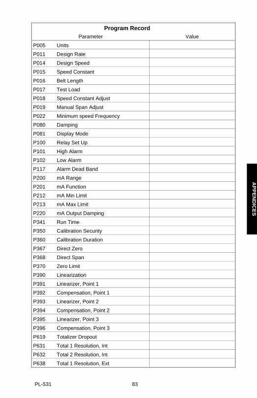
Program RecordParameter Value
P005 Units
P011 Design Rate
P014 Design Speed
P015 Speed Constant
P016 Belt Length
P017 Test Load
P018 Speed Constant Adjust
P019 Manual Span Adjust
P022 Minimum speed Frequency
P080 Damping
P081 Display Mode
P100 Relay Set Up
P101 High Alarm
P102 Low Alarm
P117 Alarm Dead Band
P200 mA Range
P201 mA Function
P212 mA Min Limit
P213 mA Max Limit
P220 mA Output Damping
P341 Run Time
P350 Calibration Security
P360 Calibration Duration
P367 Direct Zero
P368 Direct Span
P370 Zero Limit
P390 Linearization
P391 Linearizer, Point 1
P392 Compensation, Point 1
P393 Linearizer, Point 2
P394 Compensation, Point 2
P395 Linearizer, Point 3
P396 Compensation, Point 3
P619 Totalizer Dropout
P631 Total 1 Resolution, Int
P632 Total 2 Resolution, Int
P638 Total 1 Resolution, Ext
AP
PE
ND
ICE
S
PL-531 83

97/07/07
Program RecordParameter Value
P639 Total 2 Resolution, Ext
P643 Total 1 Closure, Ext
P644 Total 2 Closure, Ext
P647 Totalizer Display
P648 Totalizer Reset, Int
P751 Baud Rate
P760 Communication Mode
P761 Identification Number
P900 Software Rev.#
P949 Diagnostic Errors
P950 Zero Register
P951 Span Register
P952 Design Load
AP
PE
ND
ICE
S
PL-531 84