
Accessory Application Publication No. INSTALLATION...
5
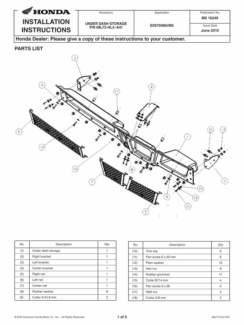
Honda Dealer: Please give a copy of these instructions to your customer. Issue Date INSTALLATION INSTRUCTIONS Accessory Application Publication No. © 2015 American Honda Motor Co., Inc. - All Rights Reserved. PARTS LIST 08L73-HL3-A41 1 of 5 UNDER DASH STORAGE P/N 08L73-HL3–A41 SXS700M4/M2 MII 15249 June 2015 No. Description Qty (1) Under dash storage 1 (2) Right bracket 1 (3) Left bracket 1 (4) Center bracket 1 (5) Right net 1 (6) Left net 1 (7) Center net 1 (8) Rubber washer 8 (9) Collar A/14.8 mm 2 No. Description Qty (10) Trim clip 6 (11) Pan screw 6 x 20 mm 6 (12) Plain washer 10 (13) Hex nut 6 (14) Rubber grommet 17 (15) Collar B/7.4 mm 4 (16) Pan screw 6 x 28 6 (17) Well nut 4 (18) Collar C/6 mm 2
Transcript of Accessory Application Publication No. INSTALLATION...
Honda Dealer: Please give a copy of these instructions to your customer.
Issue DateINSTALLATIONINSTRUCTIONS
Accessory Application Publication No.
© 2015 American Honda Motor Co., Inc. - All Rights Reserved.
PARTS LIST
08L73-HL3-A411 of 5
UNDER DASH STORAGEP/N 08L73-HL3–A41 SXS700M4/M2
MII 15249
June 2015
No. Description Qty
(1) Under dash storage 1
(2) Right bracket 1
(3) Left bracket 1
(4) Center bracket 1
(5) Right net 1
(6) Left net 1
(7) Center net 1
(8) Rubber washer 8
(9) Collar A/14.8 mm 2
No. Description Qty
(10) Trim clip 6
(11) Pan screw 6 x 20 mm 6
(12) Plain washer 10
(13) Hex nut 6
(14) Rubber grommet 17
(15) Collar B/7.4 mm 4
(16) Pan screw 6 x 28 6
(17) Well nut 4
(18) Collar C/6 mm 2

2 of 5
TOOLS AND SUPPLIES REQUIRED4 mm allen wrench
10 mm wrench
Power drill
1/2 inch drill bit
3/8 inch drill bit
Marker
Needle nose pliers
TORQUE CHARTTighten all screws, bolts, and nuts to their specified torque values.
Item N·m kgf·m Ibf·ft
Well nut bolt 1 0.1 0.7
6 mm bolt 10 1.0 7.4
USE AND CARE INFORMATIONCheck the accessory mounts frequently and retighten if necessary.
INSTALLATION1. Install the 17 rubber grommets into the holes as
shown.
HOLE HOLE HOLE
2. Install the right, left, and center nets in the locations shown by using needle nose pliers to guide the brass fitting through the rubber grommet.
LEFT NETCENTER NET RIGHT NET
3. Remove the four trim clips and two pan screws from the front lower area of the instrument panel.
PAN SCREW 6 X 8 TRIM CLIP
4. Drill out the center four holes with a 1/2 inch drill bit as shown.
NOTICE: When drilling the right hole, be careful not to drill beyond the instrument panel as the glove box could be damaged.
DRILL
5. Press the four well nuts into the holes drilled in Step 4.
NOTE: Flange of well nut should be on outside of the instrument panel.
3 of 5
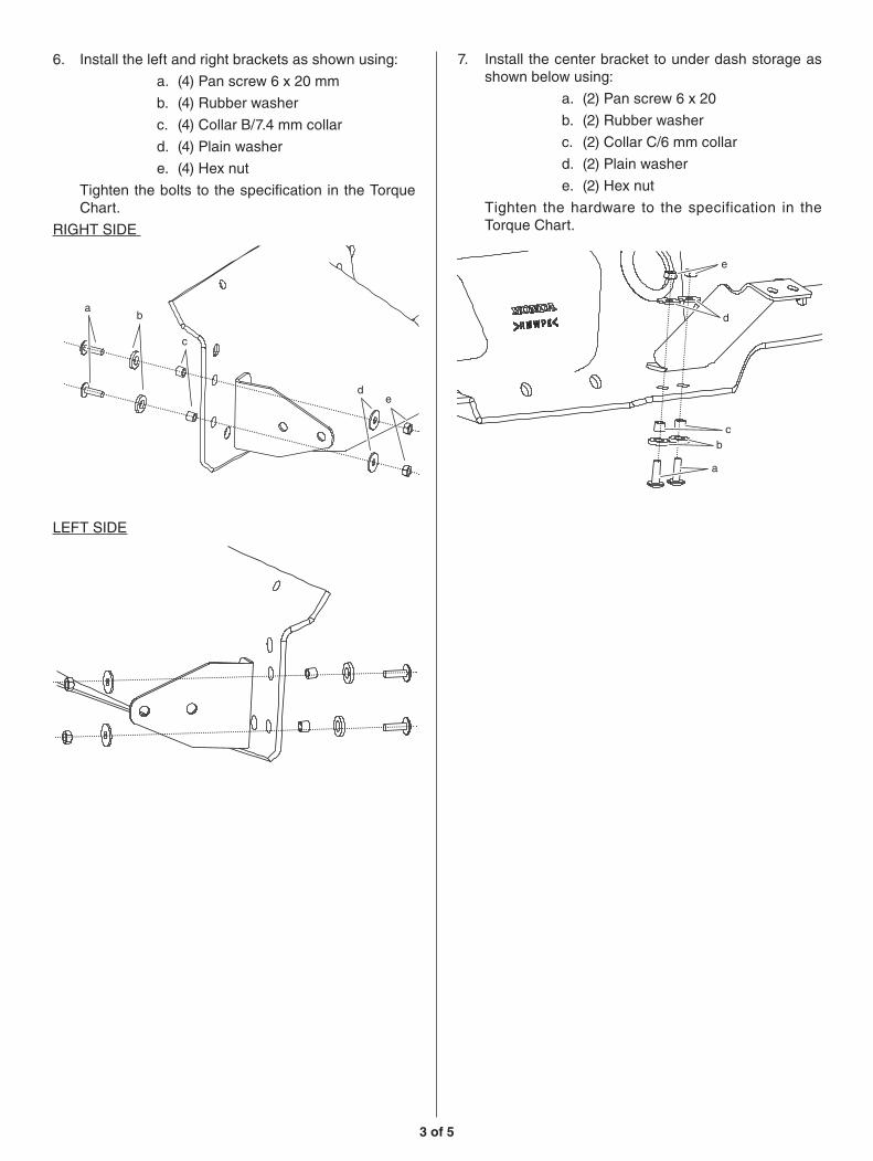
6. Install the left and right brackets as shown using:
a. (4) Pan screw 6 x 20 mm
b. (4) Rubber washer
c. (4) Collar B/7.4 mm collar
d. (4) Plain washer
e. (4) Hex nut
Tighten the bolts to the specification in the Torque Chart.
RIGHT SIDE
ab
c
de
LEFT SIDE
7. Install the center bracket to under dash storage as shown below using:
a. (2) Pan screw 6 x 20
b. (2) Rubber washer
c. (2) Collar C/6 mm collar
d. (2) Plain washer
e. (2) Hex nut
Tighten the hardware to the specification in the Torque Chart.
e
d
cb
a

4 of 5
8. Temporarily install the under dash storage partial assembly onto the instrument panel and secure the upper corners as shown using:
a. (2) Pan screw 6 x 28
b. (2) Rubber washer
c. (2) Collar A/14.8 mm collar
CORNER FASTENER
a
c
b
9. Use the left, center, & right brackets as templates to mark the position of holes to be drilled in the floor cover.
LEFT and CENTER BRACKETS
MARK HOLEMARK HOLE
RIGHT BRACKET
MARK HOLE
10. Remove parts that were installed in step 8 and remove under dash storage partial assembly.
11. Using 3/8 inch drill bit, drill holes in the floor cover at the positions marked in Step 9.
12. Reinstall the under dash storage partial assembly as shown in Step 8.
5 of 5
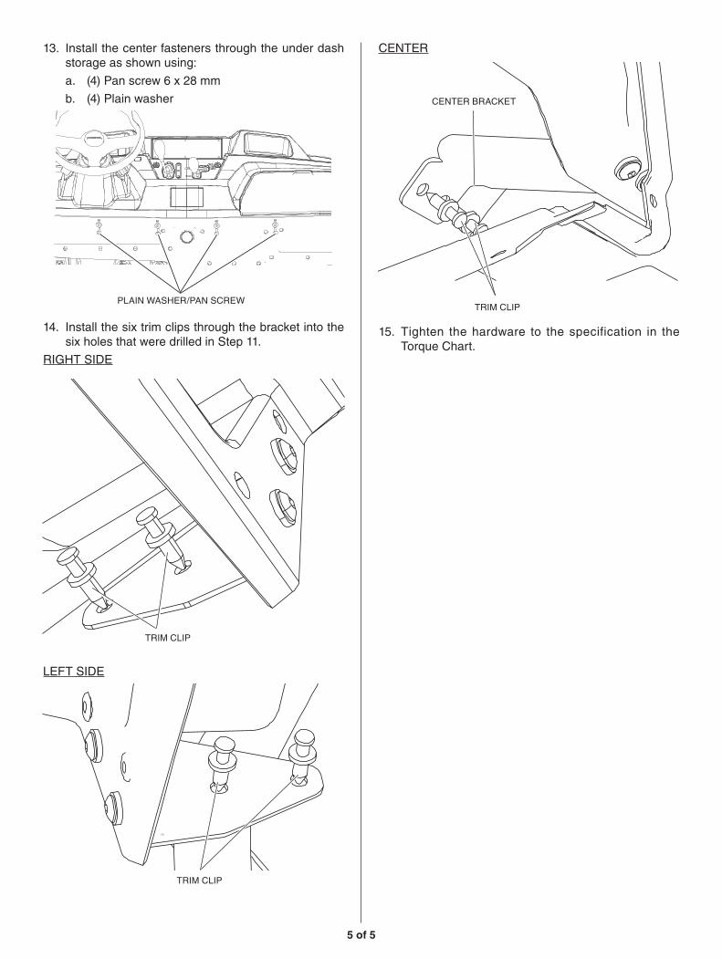
13. Install the center fasteners through the under dash storage as shown using:
a. (4) Pan screw 6 x 28 mm
b. (4) Plain washer
PLAIN WASHER/PAN SCREW
14. Install the six trim clips through the bracket into the six holes that were drilled in Step 11.
RIGHT SIDE
TRIM CLIP
LEFT SIDE
TRIM CLIP
CENTER
TRIM CLIP
CENTER BRACKET
15. Tighten the hardware to the specification in the Torque Chart.


![HL3 Series Insert Manual...with 2 side shields 0 30 30 6 92 20 ft. from burner 0 11 11 6 44 HL3 (50, 60, 70) - 200 [N, P] 0 41 41 6 94 45 63 8 10 94 with 1 side shield 0 54 8 6 94](https://static.fdocuments.net/doc/165x107/5f0527c57e708231d4118be7/hl3-series-insert-manual-with-2-side-shields-0-30-30-6-92-20-ft-from-burner.jpg)


