ACCESSORIES & OTHERS - Distritec820 Air Bleed Valves Air Bleed Valves These air bleed valves are...
21
L ACCESSORIES & OTHERS 819 ■ Accessories Page ●Air Bleed Valves ........................................................................................................................................................ 820 ●“F3” Series Pipe Flange Kits ...................................................................................................................................... 821 ●“F5” Series Pipe Flange Kits ...................................................................................................................................... 824 ●“F6” Series Pipe Flange Kits ...................................................................................................................................... 829 ■ Data Sheet ●Size of O-Ring ............................................................................................................................................................ 833 ●SAE J1926-1 SAE Straight Thread O-Ring Port ........................................................................................................ 835
Transcript of ACCESSORIES & OTHERS - Distritec820 Air Bleed Valves Air Bleed Valves These air bleed valves are...

LACCESSORIES & OTHERS
819
■ Accessories Page●Air Bleed Valves ........................................................................................................................................................ 820●“F3” Series Pipe Flange Kits ...................................................................................................................................... 821●“F5” Series Pipe Flange Kits ...................................................................................................................................... 824●“F6” Series Pipe Flange Kits ...................................................................................................................................... 829
■ Data Sheet●Size of O-Ring ............................................................................................................................................................ 833●SAE J1926-1 SAE Straight Thread O-Ring Port........................................................................................................ 835
Air Bleed Valves820
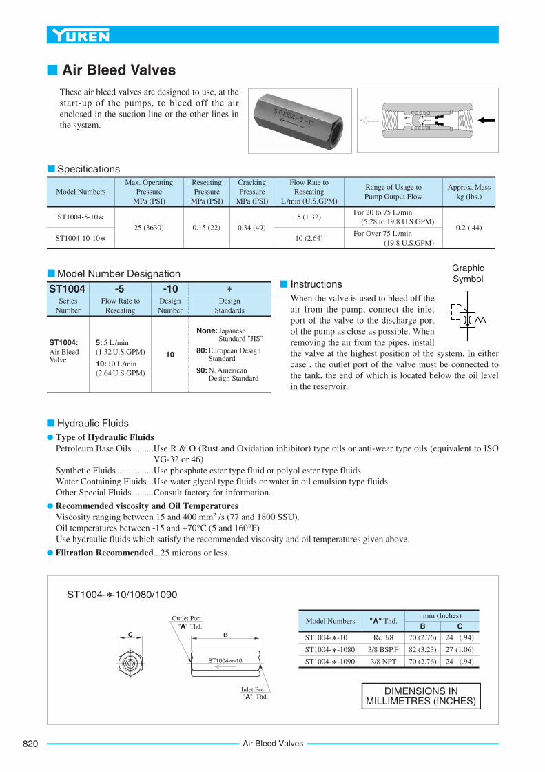
■ Air Bleed ValvesThese air bleed valves are designed to use, at thestart-up of the pumps, to bleed off the airenclosed in the suction line or the other lines inthe system.
Max. Operating Pressure
MPa (PSI)Model Numbers
Approx. Mass kg (lbs.)
CrackingPressure
MPa (PSI)
ReseatingPressure
MPa (PSI)
Flow Rate to Reseating
L/min (U.S.GPM)
Range of Usage to Pump Output Flow
ST1004-5-10
ST1004-10-10
25 (3630) 0.15 (22) 0.34 (49)
5 (1.32)
10 (2.64)
0.2 (.44)
For 20 to 75 L /min (5.28 to 19.8 U.S.GPM)
For Over 75 L /min (19.8 U.S.GPM)
Specifications
SeriesNumber
Flow Rate to Reseating
DesignNumber
DesignStandards
ST1004 -5 -10
10
None:JapaneseStandard "JIS"
80: European Design Standard
90: N. American Design Standard
ST1004:Air Bleed Valve
5: 5 L /min
10: 10 L /min
(1.32 U.S.GPM)
(2.64 U.S.GPM)
Model Number Designation■ Instructions
When the valve is used to bleed off theair from the pump, connect the inletport of the valve to the discharge portof the pump as close as possible. Whenremoving the air from the pipes, installthe valve at the highest position of the system. In eithercase , the outlet port of the valve must be connected tothe tank, the end of which is located below the oil levelin the reservoir.
GraphicSymbol
■ Hydraulic Fluids ● Type of Hydraulic Fluids
Petroleum Base Oils ........Use R & O (Rust and Oxidation inhibitor) type oils or anti-wear type oils (equivalent to ISOVG-32 or 46)
Synthetic Fluids ................Use phosphate ester type fluid or polyol ester type fluids.Water Containing Fluids ..Use water glycol type fluids or water in oil emulsion type fluids.Other Special Fluids ........Consult factory for information.
● Recommended viscosity and Oil TemperaturesViscosity ranging between 15 and 400 mm2 /s (77 and 1800 SSU).Oil temperatures between -15 and +70°C (5 and 160°F)Use hydraulic fluids which satisfy the recommended viscosity and oil temperatures given above.
● Filtration Recommended...25 microns or less.
ST1004- -10
ST1004- -1080
ST1004- -1090
Model Numbers "A" Thd.B
70 (2.76)
82 (3.23)
70 (2.76)
Rc 3/8
3/8 BSP.F
3/8 NPT
Cmm (Inches)
24
27
24
(.94)
(1.06)
(.94)
DIMENSIONS IN MILLIMETRES (INCHES)
ST1004- -10
Outlet Port "A" Thd.
C B
Inlet Port "A" Thd.
ST1004- -10/1080/1090

821
ACCESSORIES
Acc
esso
ries
“F3” Series Pipe Flange Kits
L
■ “F3” Series Pipe Flange Kits■ Specifications● Max. Operating Pressure...25 MPa (3630 PSI)
ThreadedConnection
SocketWelding
FlangeSize
DesignNumber
DesignStandards
-11
11
None:Japanese Standard "JIS" & European Design Standard
90:N. American Design Standard
None:Japanese Standard "JIS"
90:N. American Design Standard
80:European Design Standard
11
-N-A-03WF3F-Materialof Seal
SeriesNumber
Type of Pipe Connection
O-Ring & Bolts
F3
None:Standard NBR (Buna N) Seal
F:FPM (Viton) Seal (For Synthetic fluids)
A:Pipe Socket Welding
C:Block Type
B:ThreadedConnection
None:With O-Ring and Mounting Bolts
N:No O-Ring and Mounting Bolts
None:With O-Ring and Mounting Bolts
N:No O-Ring and Mounting Bolts
03W, 03, 06V
06W, 06, 10W
10, 16W, 16
24W, 24
03W, 03, 06W
06, 10W, 10
16W, 16, 24W
24
03W, 03, 06W
06, 10W, 10
16W, 16, 24W
24
03W, 03, 06V
06W, 06, 10W
10, 16W, 16
24W, 24
Type of Pipe Connection
DesignStandard
PipeThread
Mounting Bolt (Socket Head Cap Screw)
Pipe Socket Welding Block Type
Threaded Connection
Rc
BSP.F
NPT
Unified Thd.
Metric Thd.
Metric Thd.
Unified Thd.
Metric Thd.Japanese Standard "JIS" & European Design Standard
N. American Design Standard
Japanese Standard "JIS"
European Design Standard
N. American Design Standard
Model Number Designation
Three different design standards are available as shown blow. Select the suitable design standard to your requirement.

“F3” Series Pipe Flange Kits822
O-Ring O-Ring
Surface should have a good machined finish.
"H" Dia. Through 4 Places
Soc. Hd. Cap Screw (4 Pcs.)
"N"
Dia
. Max
.
"K" D
ia.
"J"
Dia
.
P
FF
LE
"D" Sq.
P
E
Customer’s Mounting Surface
Pipe Socket Welding Block Type
F3- -A -11/1190 F3- -C -11/1190
14(.55)17.1(.67)14
(.55)17.1(.67)
18(.71)17.5(.69)
14(.55)17.1(.67)
14(.55)
14(.55)17.1(.67)
18(.71)17.5(.69)25
(.98)22.1(.87)25
(.98)22.1(.87)36
(1.42)38.6
(1.52)36
(1.42)38.6
(1.52)
M10 35 Lg.
3/8-16UNC 1-1/2 Lg.
M10 35 Lg.
3/8-16UNC 1-1/2 Lg.
M22 80 Lg.
7/8-9UNC 3-1/4 Lg.
M22 80 Lg.
7/8-9UNC 3-1/4 Lg.
M16 60 Lg.
8/5-11UNC 2-1/4 Lg.
M16 60 Lg.
8/5-11UNC 2-1/4 Lg.
M12 45 Lg.
1/2-13UNC 1-3/4 Lg.
M12 45 Lg.
1/2-13UNC 1-3/4 Lg.
M10 35 Lg.
M10 35 Lg.
3/8-16UNC 1-1/2 Lg.
M10 35 Lg.
3/8-16UNC 1-1/2 Lg.
1.4 (3.1)
2.7 (6.0)
5.8 (12.8)
0.8 (1.8)
0.5 (1.1)SO-NB-G25
Approx.Mass
kg (lbs.)
Socket Head Cap Screw
O-RingDimensions mm (Inches)Piping
SizeKit Numbers
D E F H J K L N P
SO-NB-G30
SO-NB-G40
SO-NB-G60
SO-NB-G85
F3-03W- -11
F3-03W- -1190
F3-03- -11
F3-03- -1190
F3-10W- -11
F3-10W- -1190
F3-10- -11
F3-10- -1190
F3-16W- -11
F3-16W- -1190
F3-16- -11
F3-16- -1190
F3-24W- -11
F3-24W- -1190
F3-24- -11
F3-24- -1190
F3-06V- -11
F3-06W- -11
F3-06W- -1190
F3-06- -11
F3-06- -1190
1/4
3/8
1
1-1/4
1-1/2
2
2-1/2
3
54(2.13)
58(2.28)
76(2.99)
100(3.94)
140(5.51)
36(1.42)
40(1.57)
56(2.20)
73(2.87)
103(4.06)
21(.83)
21(.83)
27(1.06)
35(1.38)
14.3(.56)
11(.43)
13.5(.53)
17.5(.69)
15(.59)
20(.79)
31.5(1.24)
50(1.97)
44(1.73)
24(.94)
75(2.95)
1/2
3/4
3/8
11(.43)
11(.43)
8(.31)
17.8(.70)
12.5(.49)
9(.35)
22.2(.87)
16(.63)
11(.43)
27.7(1.09)
20(.79)
12(.47)
34.5(1.36)
25(.98)
14(.55)
16(.63)
49.1(1.93)
37.5(1.48)
18(.71)
61.1(2.41)
47.5(1.87)
20(.79)
77.1(3.04)
60(2.36)
22(.87)
90.0(3.54)
71(2.80)
25(.98)
17.8(.70)
12.5(.49)
9(.35)
43.2(1.70)
31.5(1.24)
Approx. mass is the value including socket head cap screws (4 Pcs.).

823
ACCESSORIES
Acc
esso
ries
L
“F3” Series Pipe Flange Kits
O-Ring
"H" Dia. Through 4 Places
Socket Head Cap Screw (4 Pcs.)
"J" D
ia.
F
E
"D" Sq.
P
E
"H" Dia. Through 4 Places
"D"Sq.
E"C" Thd.
Socket Head Cap Screw (4 Pcs.)
E
"L"
Dia
.
K
F
O-Ring
"C" Thd.
"J" D
ia.
P P
O-Ring
"C" Thd.K
F
"J" D
ia.
Surface should have a good machined finish.
"N" D
ia. M
ax.
0.3-1.6 mm (.01-.06 IN.)
Customer’sMountingSurface
Piping Size: 03W to 10
Piping Size: 16W to 24
Threaded Connection
F3- -B -3F0911/11- -B -1180
Japanese Standard "JIS" & N. American Design Standard
European Design Standard
Approx.Mass
kg (lbs.)
Socket Head Cap Screw
O-RingDimensions mm (Inches)Piping
Size"C" Thd.
Kit NumbersD E F H J K L N P
11 (.43)
11.5 (.45)
11 (.43)
14 (.55)
15 (.59)
14 (.55)
14 (.55)
17.5 (69)
19 (.75)
17.5 (.69)
23 (.91)
24.5 (.96)
23 (.91)
29 (1.14)
30.5 (1.20)
29 (1.14)
Rc 1/4
1/4 BSP.F
1/4 NPT
Rc 3/8
3/8 BSP.F
3/8 NPT
F3-03W-B -11
F3-03W-B -1180
F3-03W-B -1190
F3-03-B -11
F3-03-B -1180
F3-03-B -1190 3/8-16UNC 1-1/2 Lg.
SO-NB-G25
5.8 (12.8)
3/8-16UNC 1-1/2 Lg.
3/8-16UNC 1-1/2 Lg.
3/8-16UNC 1-3/4 Lg.
1/2-13UNC 1-3/4 Lg.
1/2-13UNC 2 Lg.
5/8-11UNC 2-1/2 Lg.
5/8-11UNC 2-1/2 Lg.
7/8-9UNC 3-1/4 Lg.
7/8-9UNC 3-1/4 Lg.
M10 35 Lg.
M10 35 Lg.
M10 35 Lg.
M10 35 Lg.
M10 40 Lg.
M12 45 Lg.
M12 50 Lg.
M16 60 Lg.
M16 60 Lg.
M22 80 Lg.
M22 80 Lg.
2.7 (6.0)
1.4 (3.1)
0.8 (1.8)
0.5 (1.1)
SO-NB-G30
SO-NB-G40
SO-NB-G60
SO-NB-G85
14 (.55)
14 (.55)
14 (.55)
13 (.51)
18 (.71)
15 (.59)
25 (.98)
21 (.83)
36 (1.42)
31 (1.22)
33.6 (1.32)
38.6 (1.52)
24.5 (.96)
28.5 (1.12)
15.8 (.62)
17.5 (.69)
17.5 (.69)
17.1 (.67)
14 (.55)
17.1 (.67)
17.1 (.67)
43.5 (1.71)
45 (1.77)
43.5 (1.71)
47.5 (1.87)
70 (2.76)
72.5 (2.85)
70 (2.76)
71 (2.80)
75(2.95)
50(1.97)
31.5(1.24)
20(.79)
15(.59)
12 (.47)
14 (.55)
17 (.67)
20 (.79)
21 (.83)
22 (.87)
22 (.87)
22 (.87)
20 (.79)
20 (.79)
24.3 (.96)
29 (1.14)
21 (.83)
35.5 (1.40)
43.5 (1.71)
53 (2.09)
54(2.13)
36(1.42)
21(.83)
11(.43)
31.5 (1.24)
58(2.28)
56(2.20)
13.5(.53)
73(2.87)
17.5(.69)
103(4.06)
24(.94)
40(1.57)
27(1.06)
11(.43)
76(2.99)
100(3.94)
140(5.51)
21(.83)
27(1.06)
35(1.38)
35(1.28)
39(1.54)
44(1.73)
49(1.93)
Rc3/8
Rc 1/2
1/2 BSP.F
1/2 NPT
Rc 3/4
3/4 BSP.F
3/4 NPT
Rc 1
1 BSP.F
1 NPT
Rc 1-1/4
1-1/4 BSP.F
1-1/4 NPT
Rc 1-1/2
1-1/2 BSP.F
1-1/2 NPT
Rc 2
2 BSP.F
2 NPT
Rc 2-1/2
2-1/2 BSP.F
2-1/2 NPT
Rc 3
3 BSP.F
3 NPT
F3-10W-B -11
F3-10W-B -1180
F3-10W-B -1190
F3-10-B -11
F3-10-B -1180
F3-10-B -1190
F3-16W-B -11
F3-16W-B -1180
F3-16W-B -1190
F3-16-B -11
F3-16-B -1180
F3-16-B -1190
F3-24W-B -11
F3-24W-B -1180
F3-24W-B -1190
F3-24-B -11
F3-24-B -1180
F3-24-B -1190
F3-06V-B -11
F3-06W-B -11
F3-06W-B -1180
F3-06W-B -1190
F3-06-B -11
F3-06-B -1180
F3-06-B -1190
Approx. Mass is the value including socket head cap screws (4 Pcs.).

“F5” Series Pipe Flange Kits824
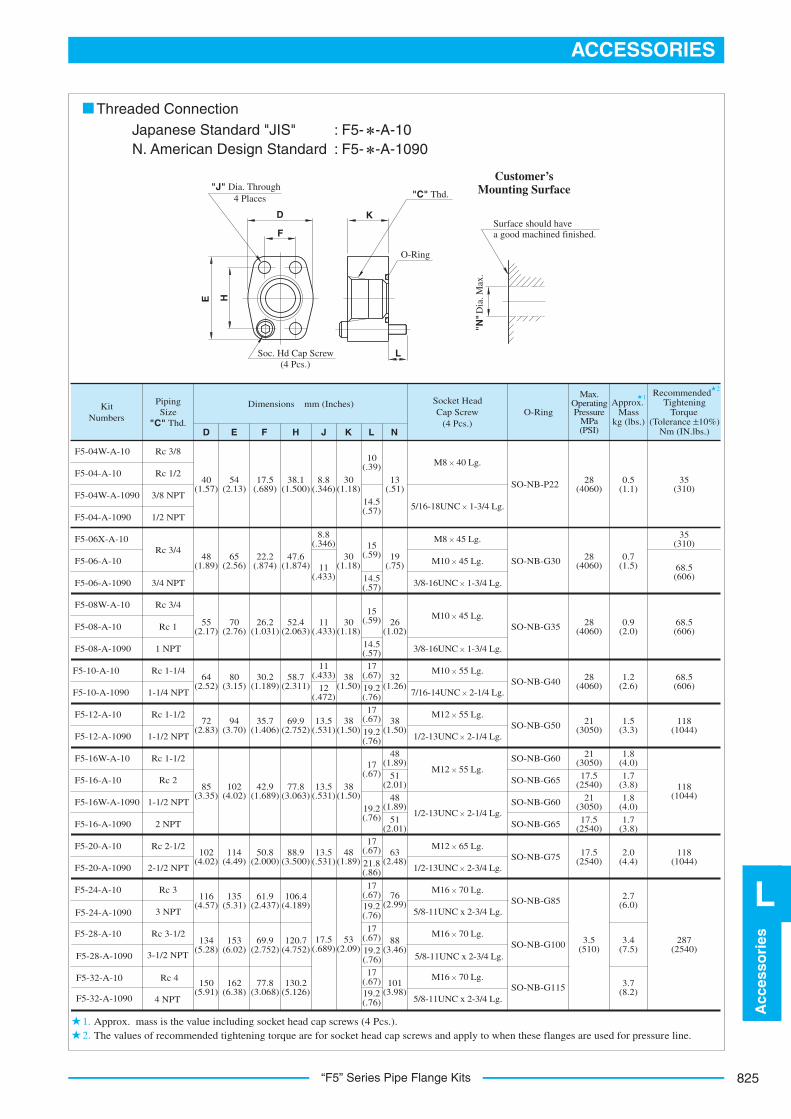
■ “F5” Series Pipe Flange Kits
■ Specifications● Max. Operating Pressure
Maximum operation pressure varies with the type of pipeconnection or flange size. Refer to the applicableinstallation drawings.
The dimensions of the flange mounting surface are basedupon SAE 4 Bolt Split Flange (Standard Pressure Series).
Threaded Connection Socket Welding
sdradnatS ngiseDrebmuN ngiseDeziS egnalF
-10-A-06F5F-Material of Seal Series Number Type of Pipe Connection
10
None:Japanese Standard "JIS"
90:N. American Design Standard
None:Japanese Standard "JIS" & European Design Standard
80:European Design Standard
F5
None:Standard NBR (Buna N) Seal
F:FPM (Viton) Seal (For Synthetic Fluids)
B: Socket Welding
04W, 04, 06X
06, 08, 08W,10
12, 16, 16W, 20
24, 28, 32
04, 06, 08
10, 12, 16
20
04W, 04, 06 08, 10, 12
16, 16W, 20
04W, 04, 06X 06, 08, 08W,10 12, 16, 16W, 20
24, 28, 32
24, 28, 32
04W, 04, 06
08, 10, 12
16, 16W, 20,24
28, 32
04, 06, 08
10, 12, 16
20
10
10
90:N. American Design Standard
None:Japanese Standard "JIS" & European Design Standard
90:N. American Design Standard
C: Butt Welding
A: Threaded Connection
Type of Pipe Connection
DesignStandard
PipeThread
Mounting Bolt (Socket Head Cap Screw)
Pipe Socket Welding Butt Welding
Threaded Connection
Rc
BSP.F
NPT
Metric Thd.
Metric Thd.
Unified Thd.
Metric Thd.Japanese Standard "JIS" & European Design Standard
N. American Design Standard
Japanese Standard "JIS"
European Design Standard
N. American Design Standard
Unified Thd.
Three different design standards are available as shown below. Select the suitable design standard to your requirement.
■ Model Number Designation
825
ACCESSORIES
Acc
esso
ries
L
“F5” Series Pipe Flange Kits
"J" Dia. Through 4 Places
DE
L
Surface should have a good machined finished.
"N" D
ia. M
ax.
FH
K
O-Ring
"C" Thd.
Soc. Hd Cap Screw (4 Pcs.)
Customer’sMounting Surface
Japanese Standard "JIS" N. American Design Standard
: F5- -A-10 : F5- -A-1090
Threaded Connection
21
1.2.
Approx.Mass
kg (lbs.)
Socket Head Cap Screw
(4 Pcs.)O-Ring
Max. Operating Pressure
MPa (PSI)
RecommendedTightening
Torque(Tolerance ±10%)
Nm (IN.lbs.)
M8 45 Lg.
M10 45 Lg.
3/8-16UNC 1-3/4 Lg.
SO-NB-G85
SO-NB-G100
SO-NB-G115
PipingSize
"C" Thd.
KitNumbers
Rc 3/8
Rc 1/2
3/8 NPT
1/2 NPT
F5-04W-A-10
F5-04-A-1038.1
(1.500)
10(.39)
13(.51)
30(1.18)
8.8(.346)
Rc 3/4
3/4 NPT
Rc 3/4
Rc 1
1 NPT
Rc 1-1/4
1-1/4 NPT
Rc 1-1/2
1-1/2 NPT
Rc 1-1/2
Rc 2
1-1/2 NPT
2 NPT
Rc 2-1/2
2-1/2 NPT
Rc 3
3 NPT
4 NPT
3-1/2 NPT
Rc 3-1/2
Rc 4
F5-04W-A-1090
F5-04-A-1090
F5-06X-A-10
F5-06-A-10
F5-06-A-1090
F5-08W-A-10
F5-08-A-10
F5-08-A-1090
F5-10-A-10
F5-10-A-1090
F5-12-A-10
F5-12-A-1090
F5-16W-A-1090
F5-16-A-1090
F5-16W-A-10
F5-16-A-10
F5-20-A-10
F5-20-A-1090
F5-24-A-10
F5-24-A-1090
F5-28-A-10
F5-28-A-1090
F5-32-A-10
F5-32-A-1090
SO-NB-G60
SO-NB-G65
SO-NB-G60
SO-NB-G65
SO-NB-G50
SO-NB-G40
SO-NB-G35
SO-NB-G30
SO-NB-P22
SO-NB-G75
28(4060)
0.5(1.1)
35(310)
35(310)
68.5(606)
68.5(606)
68.5(606)
118(1044)
118(1044)
118(1044)
287(2540)
0.7(1.5)
0.9(2.0)
1.2(2.6)
1.5(3.3)
1.8(4.0)
1.7(3.8)
1.8(4.0)
1.7(3.8)
2.0(4.4)
2.7(6.0)
3.4(7.5)
3.7(8.2)
21(3050)
17.5(2540)
21(3050)
17.5(2540)
17.5(2540)
3.5(510)
21(3050)
17.5(.689)
40(1.57)
14.5(.57)
47.6(1.874)
22.2(.874)
48(1.89)
55(2.17)
64(2.52)
72(2.83)
85(3.35)
102(4.02)
116(4.57)
134(5.28)
150(5.91)
114(4.49)
13.5(.531)
26.2(1.031)
52.4(2.063)
30.2(1.189)
58.7(2.311)
35.7(1.406)
69.9(2.752)
42.9(1.689)
77.8(3.063)
61.9(2.437)
69.9(2.752)
77.8(3.068)
50.8(2.000)
88.9(3.500)
17.5(.689)
53(2.09)
17(.67)19.2(.76)
19.2(.76)
19.2(.76)
17(.67)
17(.67)
76(2.99)
88(3.46)
101(3.98)
48(1.89)
63(2.48)21.8
(.86)
17(.67)
51(2.01)
48(1.89)
51(2.01)
48(1.89)
38(1.50)
32(1.26)
26(1.02)
19(.75)
30(1.18)11
(.433)
8.8(.346)
14.5(.57)
15(.59)
30(1.18)
38(1.50)
38(1.50)
38(1.50)
13.5(.531)
13.5(.531)
12(.472)
11(.433)
11(.433)
14.5(.57)
15(.59)
17(.67)
19.2(.76)
17(.67)
19.2(.76)
17(.67)
19.2(.76)
M8 40 Lg.
5/16-18UNC 1-3/4 Lg.
M10 45 Lg.
3/8-16UNC 1-3/4 Lg.
M10 55 Lg.
7/16-14UNC 2-1/4 Lg.
M12 55 Lg.
1/2-13UNC 2-1/4 Lg.
M12 55 Lg.
1/2-13UNC 2-1/4 Lg.
M12 65 Lg.
1/2-13UNC 2-3/4 Lg.
M16
5/8-11UNC x 2-3/4 Lg.
5/8-11UNC x 2-3/4 Lg.
5/8-11UNC x 2-3/4 Lg.
70 Lg.
M16 70 Lg.
M16 70 Lg.
28(4060)
28(4060)
28(4060)
135(5.31)
153(6.02)
162(6.38)
70(2.76)
80(3.15)
94(3.70)
102(4.02)
54(2.13)
65(2.56)
106.4(4.189)
120.7(4.752)
130.2(5.126)
Dimensions mm (Inches)
D E F J K L NH
Approx. mass is the value including socket head cap screws (4 Pcs.).The values of recommended tightening torque are for socket head cap screws and apply to when these flanges are used for pressure line.
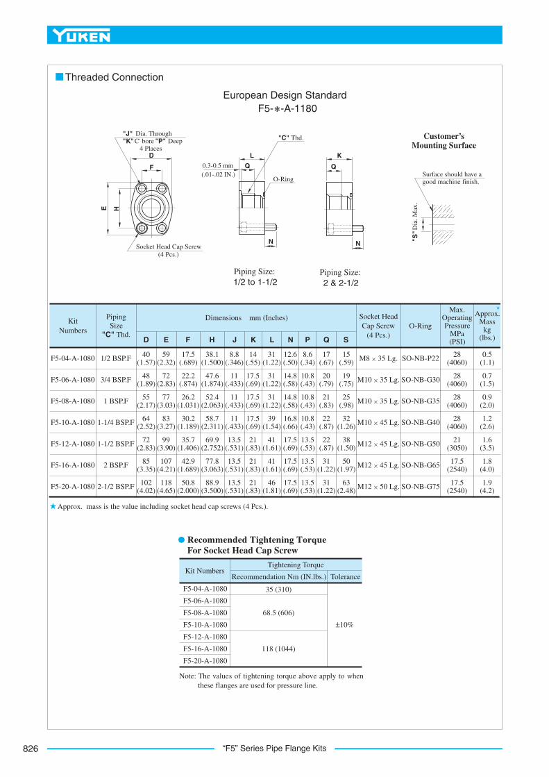
“F5” Series Pipe Flange Kits826
"J" Dia. Through "K" C' bore "P" Deep 4 Places
D
E
N
Surface should have a good machine finish.
"S"
Dia
. Max
.
F
H
L
O-Ring
"C" Thd.
Socket Head Cap Screw (4 Pcs.)
N
Q0.3-0.5 mm(.01-.02 IN.)
K
Q
Customer’sMounting Surface
European Design Standard F5- -A-1180
Piping Size:1/2 to 1-1/2
Piping Size:2 & 2-1/2
Threaded Connection
PipingSize
"C" Thd.
KitNumbers
Dimensions mm (Inches)
D E F J K L NH
F5-04-A-1080
F5-06-A-1080
F5-08-A-1080
F5-10-A-1080
F5-12-A-1080
F5-16-A-1080
F5-20-A-1080
1/2 BSP.F
3/4 BSP.F
1 BSP.F
1-1/4 BSP.F
1-1/2 BSP.F
2 BSP.F
2-1/2 BSP.F
40(1.57)
59(2.32)
17.5(.689)
38.1(1.500)
8.8(.346)
14(.55)
31(1.22)
12.6(.50)
8.6(.34)
17(.67)
15(.59)
Socket Head Cap Screw
(4 Pcs.)
M8 35 Lg.
M10 35 Lg.
M10 35 Lg.
M10 45 Lg.
M12 45 Lg.
M12 45 Lg.
M12 50 Lg.
SO-NB-P22
SO-NB-G30
SO-NB-G35
SO-NB-G40
SO-NB-G50
SO-NB-G65
SO-NB-G75
Approx.Mass
kg(lbs.)
O-Ring
0.5(1.1)
Max.OperatingPressure
MPa(PSI)P Q S
28(4060)
0.7(1.5)
0.9(2.0)
1.2(2.6)
21(3050)
1.6(3.5)
17.5(2540)
1.8(4.0)
17.5(2540)
1.9(4.2)
48(1.89)
72(2.83)
22.2(.874)
47.6(1.874)
11(.433)
17.5(.69)
31(1.22)
14.8(.58)
10.8(.43)
20(.79)
19(.75)
55(2.17)
77(3.03)
26.2(1.031)
52.4(2.063)
11(.433)
17.5(.69)
31(1.22)
14.8(.58)
10.8(.43)
21(.83)
25(.98)
64(2.52)
83(3.27)
30.2(1.189)
58.7(2.311)
11(.433)
17.5(.69)
39(1.54)
16.8(.66)
10.8(.43)
22(.87)
32(1.26)
72(2.83)
99(3.90)
35.7(1.406)
69.9(2.752)
13.5(.531)
21(.83)
41(1.61)
17.5(.69)
13.5(.53)
38(1.50)
85(3.35)
107(4.21)
42.9(1.689)
77.8(3.063)
13.5(.531)
21(.83)
41(1.61)
17.5(.69)
50(1.97)
102(4.02)
118(4.65)
50.8(2.000)
88.9(3.500)
13.5(.531)
21(.83)
46(1.81)
17.5(.69)
31(1.22)
63(2.48)
31(1.22)
22(.87)
13.5(.53)
13.5(.53)
28(4060)
28(4060)
28(4060)
F5-04-A-1080
F5-06-A-1080
F5-08-A-1080
F5-10-A-1080
F5-12-A-1080
F5-16-A-1080
F5-20-A-1080
Kit NumbersRecommendation Nm (IN.lbs.) Tolerance
Tightening Torque
35 (310)
68.5 (606)
118 (1044)
±10%
Approx. mass is the value including socket head cap screws (4 Pcs.).
Note: The values of tightening torque above apply to when these flanges are used for pressure line.
euqroT gninethgiT dednemmoceRFor Socket Head Cap Screw

827
ACCESSORIES
Acc
esso
ries
L
“F5” Series Pipe Flange Kits
"J" Dia. Through 4 Places
D
Socket Head Cap Screw (4 Pcs.)
E
L
Surface should have a good machined finish.
"S"
Dia
. Max
.
F
H
Q
K
O-Ring"N
" D
ia.
Customer’sMountingSurface
Japanese Standard "JIS" & European Design Standard : F5- -B-10N. American Design Standard : F5- -B-1090
Socket Welding
F5-04W-BF5-04-BF5-06X-BF5-06-BF5-08W-BF5-08-BF5-10-BF5-12-BF5-16W-BF5-16-BF5-20-BF5-24-BF5-28-BF5-32-B
Kit Numbers RecommendationNm (IN.lbs.)
Tolerance
Tightening Torque
35 (310)
68.5 (660)
118 (1044)
287 (2540)
±10%
Recommended Tightening Torque For Socket Head Cap Screw
Note: The values of tightening torque above apply to when these flanges are used for pressure line.
Approx.Mass
kg (lbs.)
Socket Head Cap Screw
(4 Pcs.)O-Ring
Dimensions mm (Inches)PipingSize
Kit Numbers
D E F J K L N
10(.39)
SO-NB-P22
M8 40 Lg.
5/16-18UNC 1-3/4 Lg.
M8 40 Lg.
5/16-18UNC 1-3/4 Lg.
M8 45 Lg.
M10 45 Lg.
3/8-16UNC 1-3/4 Lg.
28(4060)
Max. Operating Pressure
MPa(PSI)
14.5(.57)
10(.39)
14.5(.57)
15(.59)
15(.59)
14.5(.57)
14.5(.57)
17(.67)
19.2(.76)
17(.67)
19.2(.76)
17(.67)
19.2(.76)
17(.67)
19.2(.76)
17(.67)
21.8(.86)
17(.67)
19.2(.76)
17(.67)
19.2(.76)
17(.67)
19.2(.76)
3/8
M10 45 Lg.
3/8-16UNC 1-3/4 Lg.
M10 55 Lg.
7/16-14UNC 2-1/4 Lg.
M12 55 Lg.
1/2-13UNC 2-1/4 Lg.
M12 55 Lg.
1/2-13UNC 2-1/4 Lg.
M12 55 Lg.
1/2-13UNC 2-1/4 Lg.
M12 65 Lg.
1/2-13UNC 2-3/4 Lg.
M16 55 Lg.
5/8-11UNC 2-1/4 Lg.
M16 55 Lg.
5/8-11UNC 2-1/4 Lg.
M16 55 Lg.
5/8-11UNC 2-1/4 Lg.
SO-NB-G100
SO-NB-G115
SO-NB-G85
SO-NB-G75
SO-NB-G65
SO-NB-G60
SO-NB-G50
SO-NB-G40
SO-NB-G35
SO-NB-G30
28(4060)
14(2030)
28(4060)
14(2030)
14(2030)
14(2030)
21(3050)
10.5(1520)
7(1020)
3.5(510)
3.5(510)
3.5(510)
0.5(1.1)
0.7(1.5)
0.9(2.0)
1.2(2.7)
1.5(3.3)
1.8(3.7)
1.7(3.8)
2.0(4.4)
2.7(6.0)
3.4(7.5)
3.7(8.2)
48(1.89)
51(2.01)
63(2.48)
76(2.99)
88(3.46)
101(3.98)
38(1.50)
32(1.26)
26(1.02)
19(.75)
13(.51)
30(1.18)
8.8(.346)
38.1(1.500)
17.5(.689)
54(2.13)
40(1.57)
17.8(.701)
9(.35)
22.2(.874)
11(.43)
27.7(1.091)
12(.47)
30(1.18)
47.6(1.874)
22.2(.874)
65(2.56)
48(1.89)
30(1.18)
11(.433)
52.4(2.063)
26.2(1.031)
70(2.76)
55(2.17)
16(.63)
43.2(1.701)
38(1.50)
11(.433)58.7
(2.311)30.2
(1.189)80
(3.15)64
(2.52)
18(.71)
49.1(1.933)
38(1.50)
13.5(.531)
18(.71)
49.1(1.933)
20(.79)
61.1(2.406)
38(1.50)
77.8(3.063)
42.9(1.689)
102(4.02)
85(3.35)
22(.87)
77.1(3.035)
48(1.89)
88.9(3.500)
50.8(2.000)
114(4.49)
102(4.02)
25(.98)
90.0(3.543)
38(1.50)
13.5(.531)
106.4(4.189)
61.9(2.437)
135(5.31)
116(4.57)
28(1.10)
102.8(4.047)
38(1.50)
17.5(.689)
120.7(4.752)
69.9(2.752)
153(6.02)
134(5.28)
31.5(1.24)
115.5(4.547)
38(1.50)
17.5(.689)
130.2(5.126)
77.8(2.063)
162(6.38)
150(5.91)
14(.55)
34.5(1.358)
27.7(1.091)
12(.47)
11(.433)
8.8(.346)
Q SH
17.5(.689)
13.5(.531)
1/2
3/4
3/4
1
1-1/4
1-1/2
1-1/2
2
2-1/2
3
3-1/2
4
F5-04W-B-10
F5-04W-B-1090
F5-04-B-10
F5-04-B-1090
F5-06X-B-10
F5-06-B-10
F5-06-B-1090
F5-08W-B-10
F5-08-B-10
F5-08-B-1090
F5-10-B-10
F5-10-B-1090
F5-12-B-10
F5-12-B-1090
F5-16W-B-10
F5-16W-B-1090
F5-16-B-10
F5-16-B-1090
F5-20-B-10
F5-20-B-1090
F5-24-B-10
F5-24-B-1090
F5-28-B-10
F5-28-B-1090
F5-32-B-10
F5-32-B-1090
12(.472)
69.9(2.752)
35.7(1.406)
94(3.70)
72(2.83)
Approx. mass is the value including socket head cap screws (4 Pcs.).

“F5” Series Pipe Flange Kits828
"J" Dia. Through 4 Places
D
E
L
Surface should have a good machined finish.
"Q"
Dia
.
F
H
O-Ring
Socket Head Cap Screw (4 Pcs.)
K
N
"S" D
ia. M
ax.
Customer’sMounting Surface
Japanese Standard "JIS" & European Design Standard : F5- -C-10N. American Design Standard : F5- -C-1090
Butt Welding
M8 30 Lg.
5/16-18UNC 1-1/4 Lg.SO-NB-P22
SO-NB-G30
SO-NB-G35
SO-NB-G40
SO-NB-G50
SO-NB-G65
SO-NB-G75
Approx.Mass
kg (lbs.)
Socket Head Cap Screw
(4 Pcs.)O-Ring
Max.OperatingPressure
MPa (PSI)
PipingSize
Kit Numbers
F5-04-C-10
F5-04-C-1090
13(.51)
Dimensions mm (Inches)
D E F H J K L N Q S
1/2
3/4
1
1-1/4
1-1/2
2
2-1/2
19(.75)
26(1.02)
32(1.26)
38(1.50)
51(2.01)
63(2.48)
M10 35 Lg.
3/8-16UNC 1-1/2 Lg.
M10 35 Lg.
3/8-16UNC 1-1/2 Lg.
M10 35 Lg.
7/16-14UNC 1-1/2 Lg.
M12 40 Lg.
1/2-13UNC 1-1/2 Lg.
M12 40 Lg.
1/2-13UNC 1-1/2 Lg.
M12 45 Lg.
1/2-13UNC 1-3/4 Lg.
28(4060)
28(4060)
28(4060)
28(4060)
21(3050)
17.5(2540)
14(2030)
0.25(.6)
0.35(.8)
0.45(1.0)
0.63(1.4)
1.3(2.9)
1.3(2.9)
1.4(3.1)
21.7(.85)
27.2(1.07)
34(1.34)
42.7(1.68)
48.6(1.91)
60.5(2.38)
76.3(3.00)
17(.67)
39(1.54)
41(1.61)
42(1.65)
44(1.73)
50(1.97)
50(1.97)
50(1.97)
8.8(.346)
11(.433)
11(.433)
13.5(.531)
13.5(.531)
13.5(.531)
38.1 (1.500)
54(2.13)
65(2.56)
70(2.76)
80(3.15)
94(3.70)
114(4.49)
40(1.57)
48(1.89)
55(2.17)
64(2.52)
72(2.83)
85(3.35)
102(4.02)
17.5 (.689)
13(.51)14.8(.58)16
(.63)19.1(.75)16
(.63)19.1(.75)16
(.63)19.1(.75)18
(.71)
18(.71)
20(.79)19.5(.77)
11(.433)
12(.472)
47.6 (1.874)
22.2 (.874)
52.4 (2.063)
26.2 (1.031)
58.7 (2.311)
30.2 (1.189)
69.9 (2.752)
35.7 (1.406)
77.8 (3.063)
42.9 (1.689)
88.9 (3.500)
50.8 (2.000)
19(.75)
19(.75)
19(.75)
22(.87)
22(.87)
25(.98)
F5-06-C-10
F5-06-C-1090
F5-08-C-10
F5-08-C-1090
F5-10-C-10
F5-10-C-1090
F5-12-C-10
F5-12-C-1090
F5-16-C-10
F5-16-C-1090
F5-20-C-10
F5-20-C-1090
F5-04-C
F5-06-C
F5-08-C
F5-10-C
Kit Numbers RecommendationNm (IN.lbs.)
Tolerance
Tightening Torque
35 (310)
68.5 (660)
118 (1044)
±10%
F5-12-C
F5-16-C
F5-20-C
102(4.02)
16.1(.63)
16.1(.63)
Approx. mass is the value including socket head cap screws (4 Pcs.).
Recommended Tightening Torque For Socket Head Cap Screw
Note: The values of tightening torque above apply to when these flanges are used for pressure line.
829
ACCESSORIES
Acc
esso
ries
L
“F6” Series Pipe Flange Kits
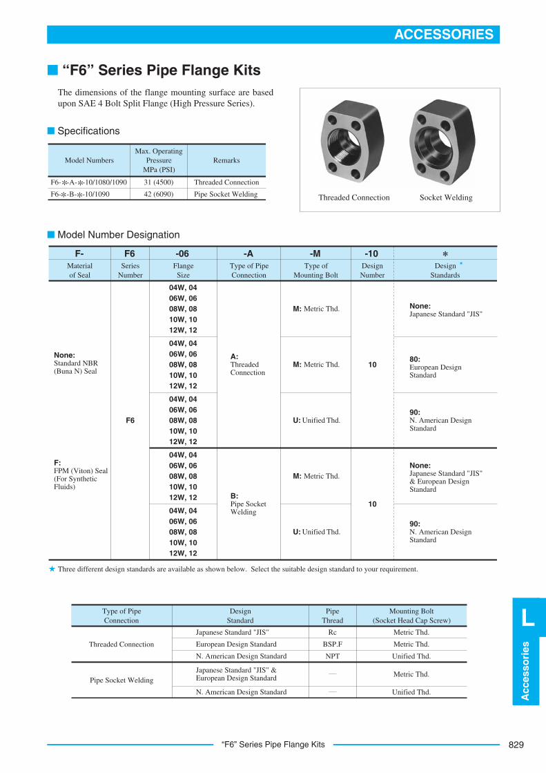
■ “F6” Series Pipe Flange Kits
■ Specifications
The dimensions of the flange mounting surface are basedupon SAE 4 Bolt Split Flange (High Pressure Series).
Threaded Connection Socket Welding
Model NumbersMax. Operating
PressureMPa (PSI)
Remarks
Threaded Connection
Pipe Socket Welding
31 (4500)
42 (6090)
F6- -A- -10/1080/1090
F6- -B- -10/1090
FlangeSize
DesignNumber
DesignStandards
-10
10
None:Japanese Standard "JIS"
90:N. American Design Standard
None:Japanese Standard "JIS" & European Design Standard
90:N. American Design Standard
80:European Design Standard
10
-M-A-06F6F-Materialof Seal
SeriesNumber
Type of Pipe Connection
Type of Mounting Bolt
F6
None:Standard NBR (Buna N) Seal
F:FPM (Viton) Seal (For Synthetic Fluids)
B:Pipe Socket Welding
A:ThreadedConnection
04W, 04 06W, 06 08W, 08 10W, 10 12W, 12
04W, 04 06W, 06 08W, 08 10W, 10 12W, 12
04W, 04 06W, 06 08W, 08 10W, 10 12W, 12
04W, 04 06W, 06 08W, 08 10W, 10 12W, 12
04W, 04 06W, 06 08W, 08 10W, 10 12W, 12
M: Metric Thd.
M: Metric Thd.
U: Unified Thd.
M: Metric Thd.
U: Unified Thd.
Type of Pipe Connection
DesignStandard
PipeThread
Mounting Bolt (Socket Head Cap Screw)
Pipe Socket Welding
Threaded Connection
Rc
BSP.F
NPT
Metric Thd.
Metric Thd.
Unified Thd.
Metric Thd.Japanese Standard "JIS" & European Design Standard
N. American Design Standard
Japanese Standard "JIS"
European Design Standard
N. American Design Standard
Unified Thd.
Three different design standards are available as shown below. Select the suitable design standard to your requirement.
■ Model Number Designation

“F6” Series Pipe Flange Kits830
Surface should have a good machined finish.
"N"
Dia
. Max
.
"J" Dia. Through 4 Places
D
E
L
F
H
K
O-Ring
"C" Thd.
Soc. Head Cap Screw (4 Pcs.)
Customer’sMounting Surface
Japanese Standard "JIS" N. American Design Standard
: F6- -A-M-10 : F6- -A-U-1090
■ Threaded Connection
1.
2.
21
Approx.Mass
kg (lbs.)
Socket Head Cap Screw
(4 Pcs.)O-Ring
RecommendedTightening
Torque(Tolerance ±10%)
Nm (IN.lbs.)
PipingSize
"C" Thd.
KitNumbers
Dimensions mm (Inches)
D E F J L N
Rc 3/8
Rc 1/2
3/8 NPT
1/2 NPT
F6-04W-A-M-10
F6-04-A-M-10
F6-04W-A-U-1090
F6-04-A-U-1090
SO-NB-P22
SO-NB-G30
SO-NB-G35
SO-NB-G40
SO-NB-G50
0.4(.9)
35(310)
H
5/16-18UNC 1-1/2 Lg.
K
F6-06W-A-M-10
F6-06-A-M-10
F6-06W-A-U-1090
F6-06-A-U-1090
F6-08W-A-M-10
F6-08-A-M-10
F6-08W-A-U-1090
F6-08-A-U-1090
F6-10W-A-M-10
F6-10-A-M-10
F6-10W-A-U-1090
F6-10-A-U-1090
F6-12W-A-M-10
F6-12-A-M-10
F6-12W-A-U-1090
F6-12-A-U-1090
Rc 1/2
Rc 3/4
1/2 NPT
3/4 NPT
Rc 3/4
Rc 1
3/4 NPT
1 NPT
Rc 1
Rc 1-1/4
1 NPT
1-1/4 NPT
Rc 1-1/4
Rc 1-1/2
1-1/4 NPT
1-1/2 NPT
3/8-16UNC 1-3/4 Lg.
M12 45 Lg.
M12 50 Lg.
7/16-14UNC 1-3/4 Lg.
7/16-14UNC 2 Lg.
M12 50 Lg.
M12 55 Lg.
1/2-13UNC 2 Lg.
1/2-13UNC 2-1/4 Lg.
M16 55 Lg.
M16 60 Lg.
5/8-11UNC 2-1/4 Lg.
5/8-11UNC 2-1/2 Lg.
M8 40 Lg.
M10 45 Lg.
0.9(2.0)
1.1(2.4)
1.3(2.9)
1.5(3.3)
68.5(606)
118(1044)
118(1044)
287(2540)
30(1.18)
34(1.34)
26.5(1.04)
34(1.34)
16(.63)
18(.71)
16.8(.66)
15(.59)
16(.63)
15(.59)
12.1(.48)
15(.59)
28(1.10)
26(1.02)
30(1.18)
21(.83)
26(1.02)
34(1.34)
44(1.73)
16.8(.66)
18.2(.72)
14.5(.57)
21(.83)
23.2(.91)
24.5(.96)
34(1.34)
39(1.54)
34(1.34)
39(1.54)
34(1.34)
39(1.54)
34(1.34)
39(1.54)
8.8(.346)
11(.433)
13.5(.531)
13.5(.531)
17.5(.689)
81(3.19)
95(3.74)
113(4.45)
77.5(3.05)
56.5(2.22)
57.5(2.26)
48(1.89)
65(2.56)
72(2.83)
90(3.54)
18.2(.717)
40.5(1.594)
23.8(.937)
50.8(2.000)
27.8(1.094)
57.2(2.252)
31.8(1.252)
66.7(2.626)
36.5(1.437)
79.4(3.126)
12(.47)
Approx. mass is the value including socket head cap screws (4 Pcs.).
The values of recommended tightening torque are for socket head cap screws.
831
ACCESSORIES
Acc
esso
ries
L
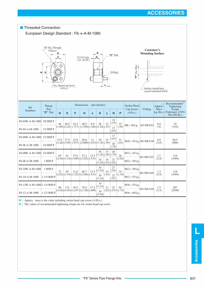
“F6” Series Pipe Flange Kits
Surface should have a good machined finish.
"P"
Dia
. Max
.
"J" Dia. Through 4 Places
D
E
L
F
H
N
O-Ring
"C" Thd.
Soc. Head Cap Screw (4 Pcs.)
K
0.3-0.5 mm(.01-.02 IN.)
European Design Standard : F6- -A-M-1080
Customer’sMounting Surface
■ Threaded Connection
1.2.
21
Approx.Mass
kg (lbs.)
Socket Head Cap Screw
(4 Pcs.)O-Ring
RecommendedTightening
Torque(Tolerance ±10%)
Nm (IN.lbs.)
PipingSize
"C" Thd.
KitNumbers
Dimensions mm (Inches)
D E F J L NH K
3/8 BSP.F
1/2 BSP.F
1/2 BSP.F
3/4 BSP.F
3/4 BSP.F
1 BSP.F
1 BSP.F
1-1/4 BSP.F
1-1/4 BSP.F
1-1/2 BSP.F
F6-04W-A-M-1080
F6-04-A-M-1080
SO-NB-P22
SO-NB-G30
SO-NB-G35
SO-NB-G40
SO-NB-G50
M8 40 Lg.
M10 45 Lg.
14(.55) 15
(.59)
P
M12 45 Lg.
M12 50 Lg.
M12 50 Lg.
M12 55 Lg.
M16 55 Lg.
M16 60 Lg.
F6-06W-A-M-1080
F6-06-A-M-1080
F6-08W-A-M-1080
F6-08-A-M-1080
F6-10W-A-M-1080
F6-10-A-M-1080
F6-12W-A-M-1080
F6-12-A-M-1080
0.4(.9)
35(310)
68.5(606)
118(1044)
118(1044)
287(2540)
0.9(2.0)
1.1(2.4)
1.3(2.9)
1.5(3.3)
21(.83)
26(1.02)
34(1.34)
44(1.73)
17(.67)
17(.67)
20(.79)
20(.79)
21(.83)
21(.83)
22(.87)
22(.87)
12(.47)
15(.59)
15(.59)
16(.63)
16(.63)
21(.83)39
(1.54)
34(1.34)
34(1.34)
39(1.54)
34(1.34)
30(1.18)
30(1.18)
28(1.10)
8.8(.346)
11(.433)
13.5(.531)
13.5(.531)
17.5(.689)
40.5(1.594)
50.8(2.000)
57.2(2.252)
66.7(2.626)
79.4(3.126)
18.2(.717)
23.8(.937)
27.8(1.094)
31.8(1.252)
36.5(1.437)
56.5(2.22)
48(1.89)
77.5(3.05)
57.5(2.26)
81(3.19)
65(2.56)
95(3.74)
72(2.83)
113(4.45)
90(3.54)
Approx. mass is the value including socket head cap screws (4 Pcs.). The values of recommended tightening torque are for socket head cap screw.
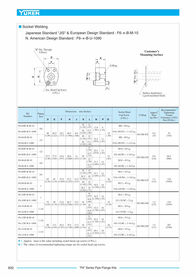
“F6” Series Pipe Flange Kits832
Surface should have a good machined finish.
"Q"
Dia
. Max
.
"J" Dia. Through 4 Places
D
E
L
F
H
K
O-Ring
Soc. Head Cap Screw (4 Pcs.)
P
"N" D
ia.
Japanese Standard "JIS" &
■ Socket Welding
European Design Standard : F6- -B-M-10
N. American Design Standard : F6- -B-U-1090
Customer’sMounting Surface
21
1.2.
Approx.Mass
kg (lbs.)
Socket Head Cap Screw
(4 Pcs.)O-Ring
RecommendedTightening
Torque(Tolerance ±10%)
Nm (IN.lbs.)
PipingSize
KitNumbers
Dimensions mm (Inches)
D E F J N QH L
3/8
1/2
1/2
3/4
3/4
1
1
1-1/4
1-1/4
1-1/2
F6-04W-B-M-10
F6-04W-B-U-1090
F6-04-B-M-10
F6-04-B-U-1090
48(1.89)
56.5(2.22)
K P
M8 40 Lg.
5/16-18UN C 1-1/2 Lg.
M8 40 Lg.
5/16-18UNC 1-1/2 Lg.
SO-NB-P22
SO-NB-G30
SO-NB-G35
SO-NB-G40
SO-NB-G50
M10 45 Lg.
3/8-16UNC 1-3/4 Lg.
M10 45 Lg.
3/8-16UNC 1-3/4 Lg.
M12 45 Lg.
7/16-14UNC 1-3/4 Lg.
M12 45 Lg.
7/16-14UNC 1-3/4 Lg.
M12 50 Lg.
1/2-13UNC 2 Lg.
M12 50 Lg.
1/2-13UNC 2 Lg.
M16 55 Lg.
5/8-11UNC 2-1/4 Lg.
M16 55 Lg.
5/8-11UNC 2-1/4 Lg.
F6-06W-B-M-10
F6-06W-B-U-1090
F6-06-B-M-10
F6-06-B-U-1090
F6-08W-B-M-10
F6-08W-B-U-1090
F6-08-B-M-10
F6-08-B-U-1090
F6-10W-B-M-10
F6-10W-B-U-1090
F6-10-B-M-10
F6-10-B-U-1090
F6-12W-B-M-10
F6-12W-B-U-1090
F6-12-B-M-10
F6-12-B-U-1090
57.5(2.26)
65(2.56)
72(2.83)
90(3.54)
18.2(.717)
40.5(1.594)
8.8(.346)
77.5(3.05)
23.8(.937)
50.8(2.000)
11(.433)
81(3.19)
27.8(1.094)
57.2(2.252)
13.5(.531)
95(3.74)
31.8(1.252)
66.7(2.626)
13.5(.531)
113(4.45)
36.5(1.437)
79.4(3.126)
17.5(.689)
28(1.10)
26(1.02)
28(1.10)
26(1.02)
30(1.18)
30(1.18)
26.5(1.04)
26.5(1.04)
12(.47)
12(.47)
12.1(.48)
12.1(.48)
15(.59)
14.5(.57)
15(.59)
14.5(.57)
15(.59)
15(.59)
18(.71)
18(.71)
16(.63)
16(.63)
16.8(.66)
16.8(.66)
21(.83)
23.2(.91)
21(.83)
23.2(.91)
30(1.18)
22.2(.874)
22.2(.874)
27.7(1.091)
27.7(1.091)
34.5(1.358)
34.5(1.358)
43.2(1.701)
43.2(1.701)
49.1(1.933)
17.8(.701)
9(.35)
11(.43)
11(.43)
12(.47)
12(.47)
14(.55)
14(.55)
16(.63)
16(.63)
18(.71)
44(1.73)
34(1.34)
26(1.02)
21(.83)
15(.59)
34(1.34)
34(1.34)
0.4(.9)
0.9(2.0)
1.1(2.4)
1.3(2.9)
1.5(3.3)
35(310)
68.5(606)
118(1044)
118(1044)
287(2540)
Approx. mass is the value including socket head cap screws (4 Pcs.).The values of recommended tightening torque are for socket head cap screws.
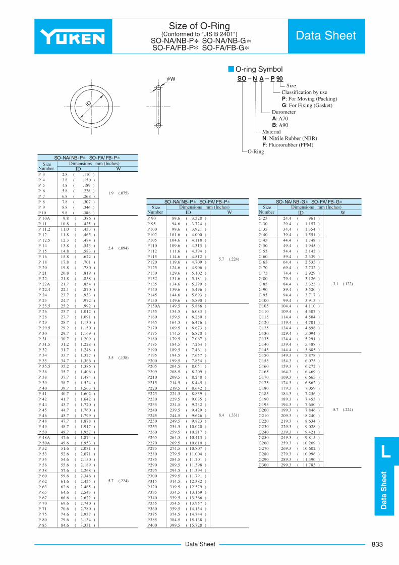
P 3 2.8 ( .110 )P 4 3.8 ( .150 )P 5 4.8 ( .189 )P 6 5.8 ( .228 )P 7 6.8 ( .268 )P 8 7.8 ( .307 )P 9 8.8 ( .346 )P 10 9.8 ( .386 )
)169.(4.4252 G)825.3(6.9809 P)683.(8.9A01 P)751.1(4.92 03 G)427.3(6.4959 P)524.(8.0111 P)453.1(4.4353 G)129.3(6.99001P)334.(0.112.11 P)155.1(4.9304 G)000.4(6.101201P)564.(8.1121 P)847.1(4.4454 G)811.4(6.401501P)484.(3.215.21 P)549.1(4.9405 G)513.4(6.901011P)345.(8.3141 P)241.2(4.4555 G)493.4(6.111211P)385.(8.4151 P)933.2(4.9506 G)215.4(6.411511P)226.(8.5161 P)535.2(4.4656 G)907.4(6.911021P)107.(8.7181 P)237.2(4.9607 G)609.4(6.421521P)087.(8.9102 P)929.2(4.4757 G)201.5(6.921031P)918.(8.0212 P)621.3(4.9708 G)181.5(6.131231P)858.(8.1222 P)323.3(4.4858 G)992.5(6.431531P)458.(7.12A22 P)025.3(4.9809 G)694.5(6.931041P)078.(1.224.22 P)717.3(4.4959 G)396.5(6.441541P)339.(7.3242 P)319.3(4.99001G)098.5(6.941051P)279.(7.4252 P)011.4(4.401501G)688.5(5.941A051P)299.(2.525.52 P)703.4(4.901011G)380.6(5.451551P)210.1(7.5262 P)405.4(4.411511G)082.6(5.951061P)190.1(7.7282 P)107.4(4.911021G)674.6(5.461561P)031.1(7.8292 P)898.4(4.421521G)376.6(5.961071P)051.1(2.925.92 P)490.5(4.921031G)078.6(5.471571P)961.1(7.9203 P)192.5(4.431531G)760.7(5.971081P)902.1(7.0313 P)884.5(4.931041G)462.7(5.481581P)822.1(2.135.13 P)586.5(4.441541G)164.7(5.981091P)842.1(7.1323 P)878.5(3.941051G)756.7(5.491591P)723.1(7.3343 P)570.6(3.451551G)458.7(5.991002P)663.1(7.4353 P)272.6(3.951061G)150.8(5.402502P)683.1(2.535.53 P)964.6(3.461561G)902.8(5.802902P)604.1(7.5363 P)566.6(3.961071G)842.8(5.902012P)484.1(7.7383 P)268.6(3.471571G)544.8(5.412512P)425.1(7.8393 P)950.7(3.971081G)246.8(5.912022P)365.1(7.9304 P)652.7(3.481581G)938.8(5.422522P)206.1(7.0414 P)354.7(3.981091G)530.9(5.922032P)246.1(7.1424 P)056.7(3.491591G)232.9(5.432532P)027.1(7.3444 P)648.7(3.991002G)924.9(5.932042P)067.1(7.4454 P)042.8(3.902012G)626.9(5.442542P)997.1(7.5464 P)436.8(3.912022G)328.9(5.942052P)878.1(7.7484 P)820.9(3.922032G)020.01(5.452552P)719.1(7.8494 P)124.9(3.932042G)712.01(5.952062P)759.1(7.9405 P)518.9(3.942052G)314.01(5.462562P)478.1(6.74A84 P)902.01(3.952062G)016.01(5.962072P)359.1(6.94A05 P)206.01(3.962072G)708.01(5.472572P)130.2(6.1525 P)699.01(3.972082G)400.11(5.972082P)170.2(6.2535 P)093.11(3.982092G)102.11(5.482582P)051.2(6.4555 P)387.11(3.992003G)893.11(5.982092P)981.2(6.5565 P
)495.11(5.492592P)862.2(6.7585 P)197.11(5.992003P)643.2(6.9506 P)283.21(5.413513P)524.2(6.1626 P)975.21(5.913023P)564.2(6.2636 P)961.31(5.433533P)345.2(6.46 56 P)663.31(5.933043P)226.2(6.6676 P)759.31(5.453553P)047.2(6.9607 P)451.41(5.953063P)087.2(6.0717 P)447.41(5.473573P)739.2(6.4757 P)831.51(5.483583P)431.3(6.9708 P)827.51(5.993004P)133.3(6.4858 P
SSO-NNA/ NB-PP SO-FFA/ FB-PPSize
NumberDimensions mm (Inches)
ID W
SO-NNA/ NB-GG SO-FFA/ FB-GGSize Dimensions mm (Inches)
SizeNumber
Dimensions mm (Inches)
3.1 (.122)
ID W
ID W
SO-NNA/ NB-PP SO-FFA/ FB-PP
8.4
1.9
2.4
3.5
5.7
(.075)
(.331)
5.7 (.224)
(.094)
(.138)
(.224)
5.7 (.224)
Number
833
Dat
aS
hee
t
L
Data Sheet
Size of O-Ring(Conformed to "JIS B 2401")
SO-NA/NB-P SO-NA/NB-G SO-FA/FB-P SO-FA/FB-G
Data Sheet
ID
φW SO – N A – P 90Size
Classification by use P: For Moving (Packing) G: For Fixing (Gasket)
Durometer A: A70 B: A90
MaterialN: Nitrile Rubber (NBR) F: Fluororubber (FPM)
O-Ring
O-ring Symbol

Data Sheet834
Size of O-Ring(Conformed to "AS568A")
SO-NA/NB-A SO-FA/FB-A Data Sheet
ID
φW
OO-r ing Symbol SO – N A – A 012
Size
A: Conformed to “AS568A”
Durometer A: A70 B: A90
MaterialN: Nitrile Rubber (NBR) F: Fluororubber (FPM)
O-Ring
( )( )( )( )( )( )( )( )( )( )( )( )( )( )( )( )( )( )( )( )( )( )( )( )( )( )( )( )( )( )( )( )( )( )( )( )( )( )( )( )( )( )( )( )( )( )( )( )( )( )( )( )( )( )( )( )( )( )( )( )( )( )( )( )( )( )( )( )( )( )
( )( )( )( )( )( )( )( )( )( )( )( )( )( )( )( )( )( )( )( )( )( )( )( )( )( )( )( )( )( )( )( )( )( )( )( )( )( )( )( )( )( )( )( )( )( )( )( )( )( )( )( )( )( )( )( )( )( )( )( )( )( )( )( )
2.903.684.475.28
18.64
6.07
20.22
7.65
21.82
9.25
23.39
10.82
24.99
12.42
26.57
14.00
28.17
15.60
29.74
17.17
31.34
18.77
32.92
20.35
34.52
21.95
36.09
23.52
37.69
25.12
40.87
26.70
44.04
28.30
50.47
47.22
29.87
52.07
50.39
31.47
53.64
53.57
33.05
55.24
56.74
34.65
56.82
59.92
37.82
58.42
63.09
41.00
59.99
66.27
44.17
61.60
69.44
47.35
63.17
72.62
50.52
64.77
75.79
53.70
66.34
78.97
56.87
67.94
82.14
60.05
69.52
85.32
63.22
71.12
88.49
66.40
72.69
91.67
69.57
75.87
94.84
72.75
82.22
98.02
75.92
88.57
101.19
82.27
94.92
104.37
88.62
101.27
107.54
94.97
107.62
110.72
101.32
113.97
113.89
107.67
120.32
117.07
114.02
126.67
120.24
120.37
133.02
123.42
126.72
139.37
126.59
133.07
145.72
129.77
152.07
132.94
158.42
136.12
164.77
139.29
171.12
142.47
177.47
145.64
10.779.19
183.82
148.82
12.37
190.17
151.99
13.94
196.52
158.34
15.54
202.87
164.69
17.12
209.22
171.04
18.72
215.57
177.39
20.29
221.92
183.74
21.89
228.27
190.09
23.47
234.62
196.44
25.07
240.97
202.79
247.32
209.14215.49221.84
SSO-NNA/ NB-AA SO-FA/ FB-AASize
NumberDimensions mm (Inches)
SO-NNA/ NB-AA SO-FFA/ FB-AASize
NumberDimensions mm (Inches)
I D W
SO-NNA/ NB-AA SO-FFA/ FB-AA
I D W
SizeNumber
Dimensions mm (Inches)ID W
26.6428.2429.8231.4232.9934.5936.1737.7739.3440.9442.5244.1245.6947.29
48.90
A006A007A008A009A010A011A012A013A014A015A016A017A018A019A020A021A022A023A024A025A026A027A028A029A030A031A032A033A034A035A036A037A038A039A040A041A042A043A044A045A046A047A048A049A050A110A111A112A113A114A115A116A117A118A119A120A121A122A123A124A125A126A127A128A129A130A131A132A133A134
A135A136A137A138A139A140A141A142A143A144A145A146A147A148A149A150A151A152A153A154A155A156A157A158A159A160A161A162A163A164A165A166A167A168A169A170A171A172A173A174A175A176A177A178A210A211A212A213A214A215A216A217A218A219A220A221A222A223A224A225A226A227A228A229
A230A231A232A233A234A235A236A237A238A239A240A241A242A243A244A245A246A247A248A249A250A251A252A253A254A255A256A257A258A259A260A261A262A263A264A265A266A267A268A269A270A271A272A273A274A901A902A903A904A905A906A907A908A909A910A911A912A913A914A916A918A920A924A928A932
.114
.145
.176
.208
.239
.301
.364
.426
.489
.551
.614
.676
.739
.801
.864
.926
.9891.0511.1141.1761.2391.3011.3641.4891.6141.7391.8641.9892.1142.2392.3642.4892.6142.7392.8642.9893.2393.4893.7393.9894.2394.4894.7394.9895.239
.362
.424
.487
.549
.612
.674
.737
.799
.862
.924
.9871.0491.1121.1741.2371.2991.3621.4241.4871.5491.6121.6741.7371.7991.862
1.9251.9872.0502.1122.1752.2372.3002.3622.4252.4872.5502.6122.6752.7372.8002.8622.9873.2373.4873.7373.9874.2374.4874.7374.9875.2375.4875.7375.9876.2376.4876.7376.9877.2377.4877.7377.9878.2378.4878.7378.9879.2379.4879.737
.734
.796
.859
.921
.9841.0461.1091.1711.2341.2961.3591.4211.4841.6091.7341.8591.9842.1092.2342.359
( )( )( )( )( )( )( )( )( )( )( )( )( )( )( )( )( )( )( )( )( )( )( )( )( )( )( )( )( )( )( )( )( )( )( )( )( )( )( )( )( )( )( )( )( )( )( )( )( )( )( )( )( )( )( )( )( )( )( )( )( )( )( )( )( )
2.4842.6092.7342.8592.9843.1093.2343.3593.4843.6093.7343.8593.9844.1094.2344.3594.4844.6094.7344.8594.9845.1095.2345.3595.4845.6095.7345.8595.9846.2346.4846.7346.9847.2347.4847.7347.9848.2348.4848.7348.9849.2349.4849.7349.984
.185
.239
.301
.351
.414
.468
.530
.644
.706
.755
.863
.924
.9861.0471.1711.3551.4751.7202.0902.337
228.19234.54240.89247.24253.59
4.70 1.426.07 1.637.64 1.638.92 1.83
10.52 1.8311.89 1.9813.46 2.0816.36 2.2117.93 2.4619.18 2.4621.9223.4725.0426.5929.7434.4237.4643.6953.09
59.36
3.00 (.118 )
2.95 (.116 )
2.62 (.103 )3.53 (.139)
3.53 (.139)
1.78 (.070 )
2.62 (.103 )
.056
.064
.064
.072
.072
.078
.082
.087
.097
.097
( )( )( )( )( )( )( )( )( )( )
835
Dat
aS
hee
t
L
Data Sheet
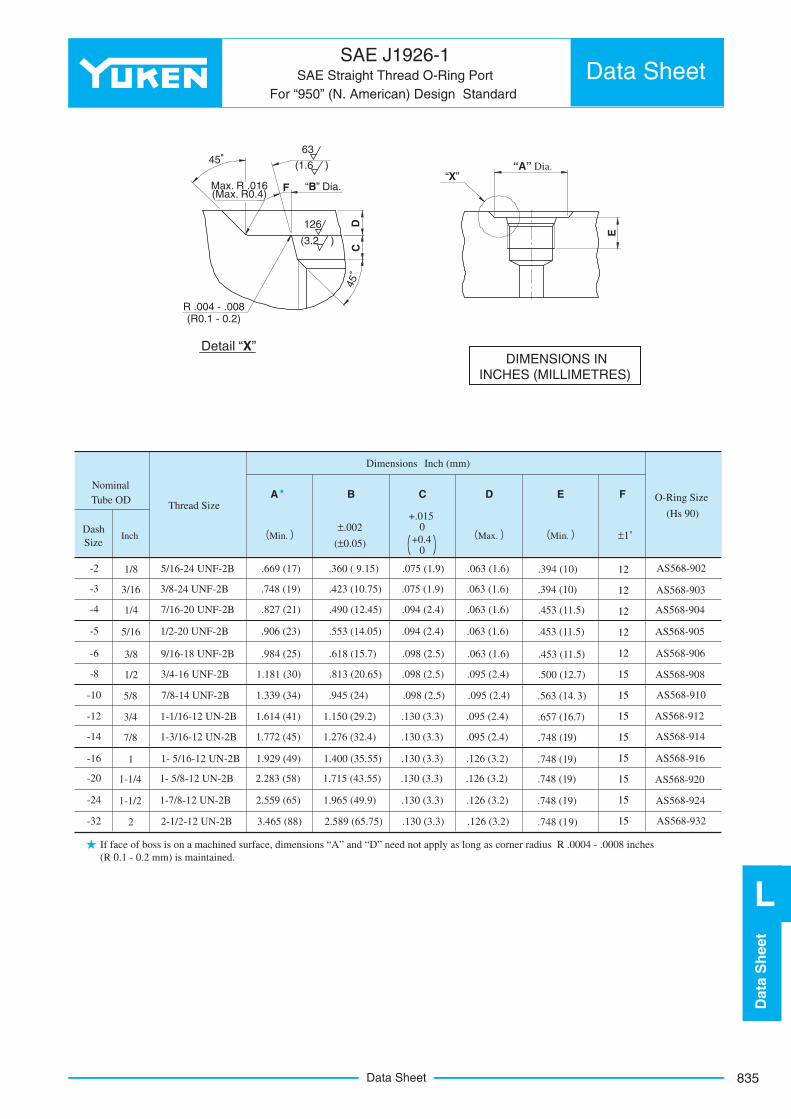
SAE J1926-1SAE Straight Thread O-Ring Port
For “950” (N. American) Design Standard
Data Sheet
45°
45°
Max. R .016(Max. R0.4)
F “B” Dia.
63
126
(1.6 )
(3.2 )
DC
R .004 - .008(R0.1 - 0.2)
Detail “X”
“X”
E
“A” Dia.
DIMENSIONS IN INCHES (MILLIMETRES)
Dimensions Inch (mm)
Nominal Tube OD A B C D E F
DashSize
Inch
Thread Size
Min.±.002
(±0.05)
+.0150
+0.40
Max. Min. ±1˚
O-Ring Size
(Hs 90)
12
12
12
12
12
15
15
15
15
15
15
15
15
-2
-3
-4
-5
-6
-8
-10
-12
-14
-16
-20
-24
-32
1/8
3/16
1/4
5/16
3/8
1/2
5/8
3/4
7/8
1
1-1/4
1-1/2
2
5/16-24 UNF-2B
3/8-24 UNF-2B
7/16-20 UNF-2B
1/2-20 UNF-2B
9/16-18 UNF-2B
3/4-16 UNF-2B
7/8-14 UNF-2B
1-1/16-12 UN-2B
1-3/16-12 UN-2B
1- 5/16-12 UN-2B
1- 5/8-12 UN-2B
1-7/8-12 UN-2B
2-1/2-12 UN-2B
.669 (17)
.748 (19)
.827 (21)
.906 (23)
.984 (25)
1.181 (30)
1.339 (34)
1.614 (41)
1.772 (45)
1.929 (49)
2.283 (58)
2.559 (65)
3.465 (88)
.360 ( 9.15)
.423 (10.75)
.490 (12.45)
.553 (14.05)
.618 (15.7)
.813 (20.65)
.945 (24)
1.150 (29.2)
1.276 (32.4)
1.400 (35.55)
1.715 (43.55)
1.965 (49.9)
2.589 (65.75)
.075 (1.9)
.075 (1.9)
.094 (2.4)
.094 (2.4)
.098 (2.5)
.098 (2.5)
.098 (2.5)
.130 (3.3)
.130 (3.3)
.130 (3.3)
.130 (3.3)
.130 (3.3)
.130 (3.3)
.063 (1.6)
.063 (1.6)
.063 (1.6)
.063 (1.6)
.063 (1.6)
.095 (2.4)
.095 (2.4)
.095 (2.4)
.095 (2.4)
.126 (3.2)
.126 (3.2)
.126 (3.2)
.126 (3.2)
.394 (10)
.394 (10)
.453 (11.5)
.453 (11.5)
.453 (11.5)
.500 (12.7)
.563 (14.3)
.657 (16.7)
.748 (19)
.748 (19)
.748 (19)
.748 (19)
.748 (19)
AS568-902
AS568-903
AS568-904
AS568-905
AS568-906
AS568-908
AS568-910
AS568-912
AS568-914
AS568-916
AS568-920
AS568-924
AS568-932
If face of boss is on a machined surface, dimensions “A” and “D” need not apply as long as corner radius R .0004 - .0008 inches (R 0.1 - 0.2 mm) is maintained.
836
(Ireland)
(United Kingdom)
(France) (Switzerland)(Austria)
(Turkey)
(Denmark)(Sweden)
(Norway)
(Egypt)
(South Africa)
New Delhi
Mumbai
Bangalore
Kolkata
Bangkok
HCMCIpoh
Singapore
Jakarta
TainanTaichung
Taipei
Hong KongHanoi
Foshan
YuciSeoul
Dalian
Irkutsk
Busan
(Netherland) (Poland)
(Spain)
(Portugal)
Colombo
Kuala Lumpur
Brisbane
Manila
Shenzhen
NingboHangzhou
Zhangjiagang
Shanghai
AUSTRIAEurofluid Hydraulik GmbH.,Europastr. 5,A-3442 Tulln-LangenrohrTel. 2272-66990Fax. 2272-66991
DENMARKHydro ServiceGlarmester Vej 18, DK-6710 EsbergTel. 75 155855Fax. 75 155093
FRANCEDHPS Sarl1 Impasse Du Jardin Renard,95110 SannoisTel. 01-3026-2626Fax. 01-3025-2737
IRELANDHydraulic Consultants &Service Ltd.Unit 3Ballymount Court Business CentreBallymount RoadWalkinstown DublinTel. 1-4565871Fax. 1-4508080
NETHERLANDMotrac Hydrauliek B. V.Dambroek 27223 DV BaakPostbus 247200AAZutphenTel. 0575-448844Fax. 0575-448866
NORWAYA/S HydranorWiths Gate 11, N-3600 KongsbergTel. 32865656Fax. 32865655
POLANDMasterpolPrzedsiebiorstwo Produkcyjno-Handlowe, 60-167 Poznanul,Olesnicka 15Tel. 061-8685911Fax. 061-8689355
PORTUGALFluidraulica-Eq. Hydraulicos LDA,Meaes-Lousado 11, VN Famalicao, 4760 LousadoTel. 252-316215Fax. 252-316280
RUSSIAZAO Enerprom-MikuniP.O. box 718, 28 Starokuzmikhinskaya str.,Irkutsk, Russia, 664033Tel. 3952-211-541Fax. 3952-255-797
SPAINKeelaviteCtra. Billabona-Asteasu, Km. 3Tel. 943 69 27 00Fax. 943 69 17 75Servitec Industriales Tecnicos SAPoligono Industrial Palmones-11Gondola-12Los Barrios(Cadiz) 11379Tel. 05-5667-7361Fax. 05-5667-7903
SWEDEN P & N HydraulicsOstra Zinkgatan 3SE-271YstadTel. 0411-186 58Fax. 0411-186 58
SWITZERLAND Oelhydraulik Hagenbuch AG.Risching 1 Ch-6030 Ebikon LUTel. 041-444-1200Fax. 041-444-1201
TURKEYMert Teknik Fabrika MalzemeleriTicaret ve Sanayi A.S.Tersane Cad No.43, (34420)Karakoy-IstanbulTel. 212-252-8435Fax. 212-245-6369
UNITED KINGDOM East Yorkshire Hydraulics Ltd.Units 4B / 4C Harpings Rd.,National Avenue, Hull HU5 4JFTel. 01482-440222Fax. 01482-440225Ovalway HydraulicEngineering Ltd.11, Cannon Park Road,Cannon Park, Middlesbrough, Cleveland, TS1 5JUTel. 01642-247106Fax. 01642-241874
E U R O P E
INDIAYuken India Ltd. (Head Office)P.B.No.16, Whitefield Road,Whitefield, Bangalore-560 066Tel. 080-28452262Fax. 080-28452261URL http://www.yukenindia.comE-mail [email protected]
(New Delhi Office)26, Community Centre, Mayapuri, Phase-1, New Delhi 110 064Tel. 011-28115545 Fax. 011-28115452
(Kolkata Office)Indra Prastha,46A, Madan Mohan Malaviya, Sarani,(Formerly Chakraberia Road, North),Ground Floor, Kolkata 700 020.Tel. 033-24544345 Fax. 033-24544348
(Mumbai Office)H-4 Ansa Industrial Estate,Saki Vihar Road, Sakinaka,Mumbai-400 072Tel. 022-28472011 Fax. 022-28472012
(Bangalore Office)B-80, 2nd Cross, 1st PhasePeenya Industrial Area,Bangalore-560 058.Tel. 080-28390225 Fax. 080-28390224
HONG KONGYuken Kogyo (H.K.) Co., Ltd.Flat 20, 7F., Block B Focal Industrial Centre,21 Man Lok Street,Hung Hom, Kowloon, Hong KongTel. 2362-2355Fax. 2765-7612E-mail [email protected]
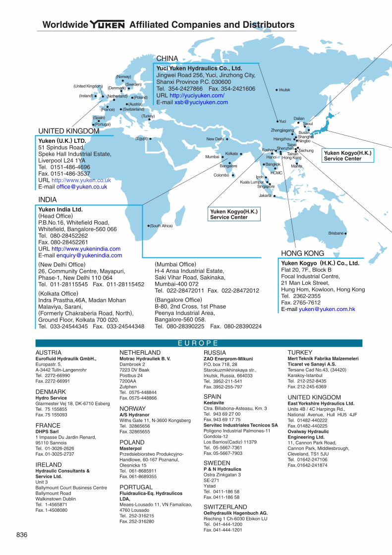
CHINAYuci Yuken Hydraulics Co., Ltd.Jingwei Road 256, Yuci, Jinzhong City, Shanxi Province P.C. 030600Tel. 354-2427866 Fax. 354-2421606URL http://yuciyuken.com/E-mail [email protected]
UNITED KINGDOMYuken (U.K.) LTD.51 Spindus Road,Speke Hall Industrial Estate, Liverpool L24 1YATel. 0151-486-4696Fax. 0151-486-3537URL http://www.yuken.co.ukE-mail [email protected]
Yuken Kogyo(H.K.)Service Center
Yuken Kogyo(H.K.)Service Center
Worldwide Affiliated Companies and Distributors
837
Mexico
(Indiana) (Michigan)
Sao Paulo
Buenos Aires
A F R I C A
NORTH, CENTRAL & SOUTH AMERICA
ASIA & AUSTRALIA/NEW ZEALAND
U.S.A./CANADAALA Industries, Ltd.1150 Southpoint CR Ste DValparaiso, IN 46385 - 6236 U.S.A.Tel. 219-465-4197Fax. 219-477-4194E-mail [email protected]
Yuken North American Service CenterServo Kinetics, Inc.3716 Plaza Drive Ann Arbor MI 48108 U.S.A.Tel. 734-996-4996Fax. 734-668-6630Bear Fluid Power34612 Centaur Clinton Township,Ml 48035, U.S.A.Tel. 586-792-2800Fax. 586-792-2882
CANADADrive Products Inc.1665 Shawson Drive, Mississauga, Ontario, Canada, L4W 1T7Tel. 905-564-5800Fax. 905-564-5799
MEXICOYukme S.A.De C.V.Zaragoza No.7,Col. Sta. Ana TlapaltitlanC.P. 50160, Toluca, EDO.DE MexicoTel. 722-270-5282Fax. 722-270-9349
ARGENTINADistritec S.A.Av.85 No.1113(B1650 HWG) San Martin,Buenos AiresTel. 11-4754-6000Fax. 11-4755-9093
BRAZILYutec Hidraulica Ltda.Rua Tiburcio de Souza, 1621, Itaim PaulistaSao Paulo S.P.CEP:08140-000Tel. 011-6568-6400Fax. 011-6568-7327Hidracomp ComponentesHidraulicos Ltda.Rua Dr. Edgard MagalhaesNoronha, 704-Vila Nova York,CEP 03480-000 Sao Paulo S.P.Tel. 011-6721-1113Fax. 011-6721-9302
EGYPTE. M. A. Co.,292 Ramsis 2 ExtensionNasr City, CairoTel. 2-3865509Fax. 2-3865509
SOUTH AFRICAErnest Lowe (Pty) Ltd.6 Skew Road Boksburg North 1460P.O. Box 6357, Dunswart, 1508Tel. 011-8944281Fax. 011-8943267
CHINAHy South Tech (SHENGZHEN) Co., Ltd.Room 2806, 28/F., News Bldg.,Shennan Rd.,Shenzhen 518027Tel. 755-82091466 Fax. 755-82091966Hy Industry (HANGZHOU) Co., Ltd.19/F Kaiser Commercial Center, No.11 Qingchun Rd.,HangzhouTel. 571-87225088Fax. 571-87225066Dalian Yuken Trading Co., Ltd.Room 1210B, Rainbow Building, No.23 Renmin Road,Zhongshan District, DalianTel. 411-39869128Fax. 411-39869127Yuken Kogyo (Zhangjiagang)Trading Co., Ltd.No.9 Xin Jing Xi Road,Zhangjiagang City, JiangsuTel. 512-5816-2355Fax. 512-5816-5199
Yuken Kogyo (H.K.) Service CenterYuken Kogyo (Ningbo) Hydraulic Technology Company Limited 1/F, Block D, No. 143,Qi Xin Road, Jiang Dong Hi-Tech Park, Jiang Dong, Ningbo,ZhejiangTel. 0574-87928836Fax. 0574-87929773Yuken Kogyo (Foshan)Hydraulic Service Co., Ltd.2B of Block No.9, Jin QiaoIndustry City, No.9 Xin Yue Road,Wu Sha, Daliang, Shunde District,Foshan City, GuangzhouTel. 757-2280-5066Fax. 757-2280-5068
INDONESIAP.T. Samudra TeknindoHydraumaticJl. Prof. Latumenten,Hasbilan ⅠⅠⅠ No.35,Jakarta Barat 11220.Tel. 021-630 8889Fax. 021-630 8989
MALAYSIAMega Engineering (M) Sdn.Bhd.No.45, Jalan PerindustrianSilibin 1, Kawasan PerindustrianRingan Silibin 30100 Ipoh, PerakTel. 05-5279823Fax. 05-5272711
PHILIPPINESL&L Optimum Commercial Corp.Lot 39 Blk. 15 Basswood St.,Greenwoods, Pasig CityTel. 2-642-4895Fax. 2-643-9241
SINGAPORETaknas Engineering (Pte.) Ltd.Block 6 No.102, Pandan LoopJurong, Singapore 128310Tel. 67775856Fax. 67796711AB Hydramec Pte, Ltd.188, Tagore Lane, Singapore 787584Tel. 64532766Fax. 64539377
SRI LANKAYuken India Ltd.(Sri Lanka Branch Office)No.15, Col. T G Jayawardana Mawatha, Colombo 03Tel. 011-2564037
TAIWANSan Shin Co., Ltd.59 Cheng Kung Road, TainanTel. 06-223-4191Fax. 06-220-0218Shinhsing Trading Co., Ltd.No.16, Lane 313Fu Hsing N.Road. TaipeiTel. 02-2712-2190Fax. 02-2712-7173
THAILANDChavanan Corporation Limited156 Sukhumvit 55 Road,Klongton Nua, Vadhana,Bangkok 10110Tel. 2714-9088Fax. 2381-1832
VIET NAMThang Long Tech Co., Ltd.82 Le Thnh Nghi Str,Hai Ba Trung Dist, HanoiTel. 4-623-0117Fax. 4-623-0116Thuy-Khi-Dien R.T.165/40 Nguyen Thai Binh Str., Dist 1, HCM CityTel. 8-8218613Fax. 8-8218614
AUSTRALIA/NEW ZEALANDACT Corporation (Australia) Pty. Ltd.5 Woorabinda Street, RuncornQLD4113, AustraliaTel. 07-3841-5788Fax. 07-3841-4088
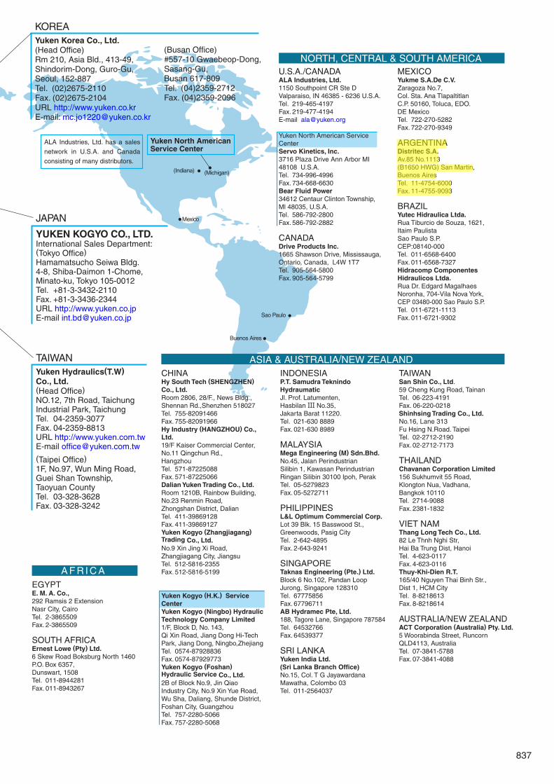
JAPAN
YUKEN KOGYO CO., LTD.International Sales Department:(Tokyo Office)Hamamatsucho Seiwa Bldg.4-8, Shiba-Daimon 1-Chome,Minato-ku, Tokyo 105-0012Tel. +81-3-3432-2110Fax. +81-3-3436-2344URL http://www.yuken.co.jpE-mail [email protected]
TAIWANYuken Hydraulics(T.W)Co., Ltd.(Head Office)NO.12, 7th Road, TaichungIndustrial Park, TaichungTel. 04-2359-3077Fax. 04-2359-8813URL http://www.yuken.com.twE-mail [email protected]
(Taipei Office)1F, No.97, Wun Ming Road, Guei Shan Township,Taoyuan CountyTel. 03-328-3628Fax. 03-328-3242
KOREAYuken Korea Co., Ltd.(Head Office) Rm 210, Asia Bld., 413-49, Shindorim-Dong, Guro-Gu, Seoul, 152-887Tel. (02)2675-2110 Fax. (02)2675-2104URL http://www.yuken.co.krE-mail: [email protected]
Yuken North AmericanService Center
(Busan Office) #557-10 Gwaebeop-Dong,Sasang-Gu, Busan 617-809Tel. (04)2359-2712 Fax. (04)2359-2096
ALA Industries, Ltd. has a sales
network in U.S.A. and Canada
consisting of many distributors.
lauradupey
Highlight
Engineering InformationCatalogue
August, 1991 First EditionMarch, 2008 Edition 11
Publisher
Yuken Kogyo Co., Ltd.Sales Planning Division,Products Publicity Section4-8, Shiba-daimon 1 Chome,Minato-ku, Tokyo 105-0012, JapanTEL: 81-3-3432-2113FAX: 81-3-3436-2344
PrinterSee code number on back cover
Please address your inquiries regardingthis catalogue to the International SalesDepartmentTEL: 81-3-3432-2110FAX: 81-3-3436-2344