Access Solutions FTTx - · PDF fileAccess Solutions FTTx G-PON Networks GE-PON Networks ......
69
Access Solutions FTTx G-PON Networks GE-PON Networks Point-to-Point Networks Business Modeling Tool Ethernet Electronics Fiber Management & Closures Optical Connectivity Installation & Maintenance Equipment
Transcript of Access Solutions FTTx - · PDF fileAccess Solutions FTTx G-PON Networks GE-PON Networks ......
Access Solutions FTTxG-PON Networks
GE-PON Networks
Point-to-Point Networks
Business Modeling Tool
Ethernet Electronics
Fiber Management & Closures
Optical Connectivity
Installation & Maintenance Equipment
www.AFLtele.com • 1.800.235.3423A Fujikura Business
AFL Telecommunications
CAT-01011 06/06
1
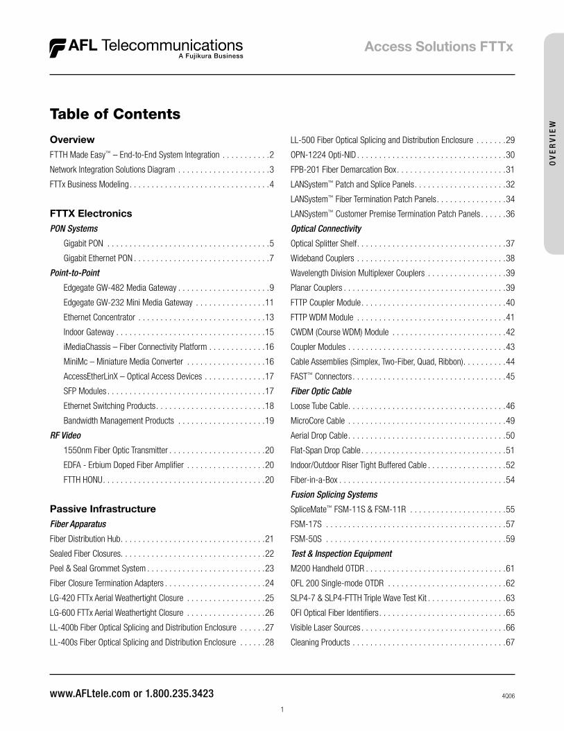
OverviewFTTH Made Easy™ – End-to-End System Integration . . . . . . . . . . .2
Network Integration Solutions Diagram . . . . . . . . . . . . . . . . . . . . .3
FTTx Business Modeling . . . . . . . . . . . . . . . . . . . . . . . . . . . . . . . .4
FTTX ElectronicsPON Systems
Gigabit PON . . . . . . . . . . . . . . . . . . . . . . . . . . . . . . . . . . . . .5
Gigabit Ethernet PON . . . . . . . . . . . . . . . . . . . . . . . . . . . . . . .7
Point-to-Point
Edgegate GW-482 Media Gateway . . . . . . . . . . . . . . . . . . . . .9
Edgegate GW-232 Mini Media Gateway . . . . . . . . . . . . . . . .11
Ethernet Concentrator . . . . . . . . . . . . . . . . . . . . . . . . . . . . .13
Indoor Gateway . . . . . . . . . . . . . . . . . . . . . . . . . . . . . . . . . .15
iMediaChassis – Fiber Connectivity Platform . . . . . . . . . . . . .16
MiniMc – Miniature Media Converter . . . . . . . . . . . . . . . . . .16
AccessEtherLinX – Optical Access Devices . . . . . . . . . . . . . .17
SFP Modules . . . . . . . . . . . . . . . . . . . . . . . . . . . . . . . . . . . .17
Ethernet Switching Products . . . . . . . . . . . . . . . . . . . . . . . . .18
Bandwidth Management Products . . . . . . . . . . . . . . . . . . . .19
RF Video
1550nm Fiber Optic Transmitter . . . . . . . . . . . . . . . . . . . . . .20
EDFA - Erbium Doped Fiber Amplifier . . . . . . . . . . . . . . . . . .20
FTTH HONU . . . . . . . . . . . . . . . . . . . . . . . . . . . . . . . . . . . . .20
Passive InfrastructureFiber Apparatus
Fiber Distribution Hub . . . . . . . . . . . . . . . . . . . . . . . . . . . . . . . . .21
Sealed Fiber Closures . . . . . . . . . . . . . . . . . . . . . . . . . . . . . . . . .22
Peel & Seal Grommet System . . . . . . . . . . . . . . . . . . . . . . . . . . .23
Fiber Closure Termination Adapters . . . . . . . . . . . . . . . . . . . . . . .24
LG-420 FTTx Aerial Weathertight Closure . . . . . . . . . . . . . . . . . .25
LG-600 FTTx Aerial Weathertight Closure . . . . . . . . . . . . . . . . . .26
LL-400b Fiber Optical Splicing and Distribution Enclosure . . . . . .27
LL-400s Fiber Optical Splicing and Distribution Enclosure . . . . . .28
LL-500 Fiber Optical Splicing and Distribution Enclosure . . . . . . .29
OPN-1224 Opti-NID . . . . . . . . . . . . . . . . . . . . . . . . . . . . . . . . . .30
FPB-201 Fiber Demarcation Box . . . . . . . . . . . . . . . . . . . . . . . . .31
LANSystem™ Patch and Splice Panels . . . . . . . . . . . . . . . . . . . . .32
LANSystem™ Fiber Termination Patch Panels . . . . . . . . . . . . . . . .34
LANSystem™ Customer Premise Termination Patch Panels . . . . . .36
Optical Connectivity
Optical Splitter Shelf . . . . . . . . . . . . . . . . . . . . . . . . . . . . . . . . . .37
Wideband Couplers . . . . . . . . . . . . . . . . . . . . . . . . . . . . . . . . . .38
Wavelength Division Multiplexer Couplers . . . . . . . . . . . . . . . . . .39
Planar Couplers . . . . . . . . . . . . . . . . . . . . . . . . . . . . . . . . . . . . .39
FTTP Coupler Module . . . . . . . . . . . . . . . . . . . . . . . . . . . . . . . . .40
FTTP WDM Module . . . . . . . . . . . . . . . . . . . . . . . . . . . . . . . . . .41
CWDM (Course WDM) Module . . . . . . . . . . . . . . . . . . . . . . . . . .42
Coupler Modules . . . . . . . . . . . . . . . . . . . . . . . . . . . . . . . . . . . .43
Cable Assemblies (Simplex, Two-Fiber, Quad, Ribbon) . . . . . . . . . .44
FAST™ Connectors . . . . . . . . . . . . . . . . . . . . . . . . . . . . . . . . . . .45
Fiber Optic Cable
Loose Tube Cable . . . . . . . . . . . . . . . . . . . . . . . . . . . . . . . . . . . .46
MicroCore Cable . . . . . . . . . . . . . . . . . . . . . . . . . . . . . . . . . . . .49
Aerial Drop Cable . . . . . . . . . . . . . . . . . . . . . . . . . . . . . . . . . . . .50
Flat-Span Drop Cable . . . . . . . . . . . . . . . . . . . . . . . . . . . . . . . . .51
Indoor/Outdoor Riser Tight Buffered Cable . . . . . . . . . . . . . . . . . .52
Fiber-in-a-Box . . . . . . . . . . . . . . . . . . . . . . . . . . . . . . . . . . . . . .54
Fusion Splicing Systems
SpliceMate™ FSM-11S & FSM-11R . . . . . . . . . . . . . . . . . . . . . .55
FSM-17S . . . . . . . . . . . . . . . . . . . . . . . . . . . . . . . . . . . . . . . . .57
FSM-50S . . . . . . . . . . . . . . . . . . . . . . . . . . . . . . . . . . . . . . . . .59
Test & Inspection Equipment
M200 Handheld OTDR . . . . . . . . . . . . . . . . . . . . . . . . . . . . . . . .61
OFL 200 Single-mode OTDR . . . . . . . . . . . . . . . . . . . . . . . . . . .62
SLP4-7 & SLP4-FTTH Triple Wave Test Kit . . . . . . . . . . . . . . . . . .63
OFI Optical Fiber Identifiers . . . . . . . . . . . . . . . . . . . . . . . . . . . . .65
Visible Laser Sources . . . . . . . . . . . . . . . . . . . . . . . . . . . . . . . . .66
Cleaning Products . . . . . . . . . . . . . . . . . . . . . . . . . . . . . . . . . . .67
Table of Contents
4Q06
OV
ER
VIE
W
© 2006, AFL Telecommunications, all rights reserved. Revision 0, 9.01.06 Specifications are subject to change without notice.
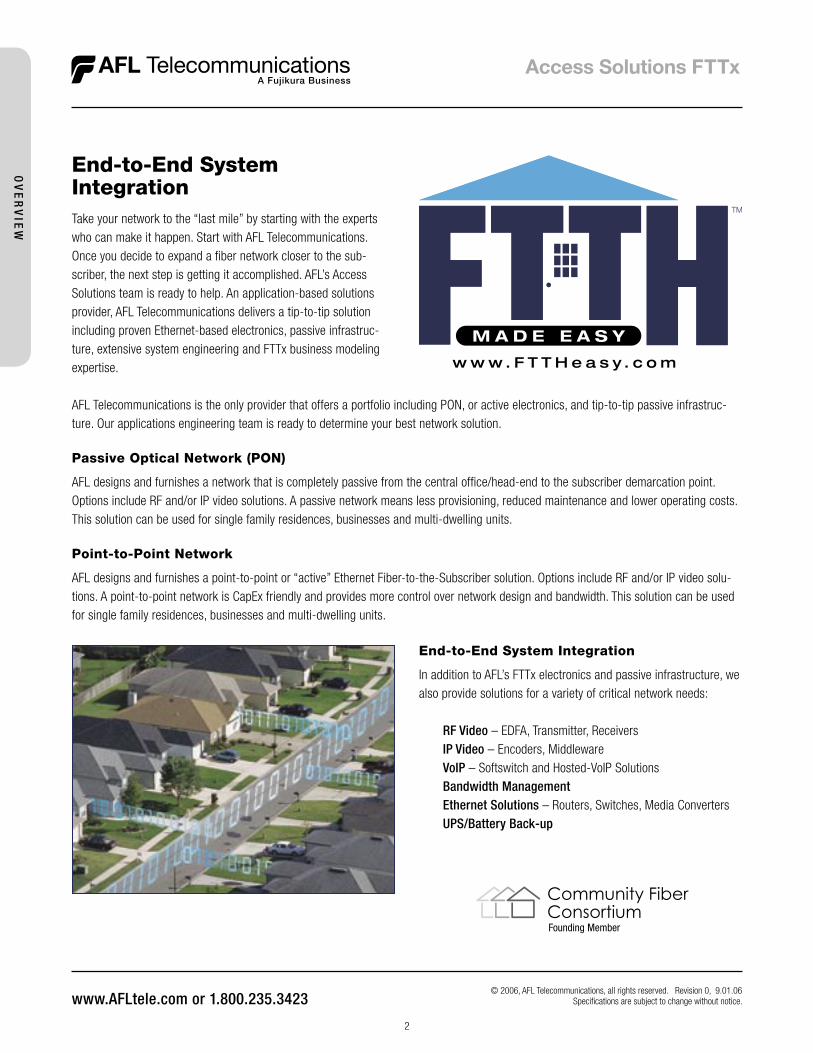
Take your network to the “last mile” by starting with the experts who can make it happen. Start with AFL Telecommunications. Once you decide to expand a fiber network closer to the sub-scriber, the next step is getting it accomplished. AFL’s Access Solutions team is ready to help. An application-based solutions provider, AFL Telecommunications delivers a tip-to-tip solution including proven Ethernet-based electronics, passive infrastruc-ture, extensive system engineering and FTTx business modeling expertise.
AFL Telecommunications is the only provider that offers a portfolio including PON, or active electronics, and tip-to-tip passive infrastruc-ture. Our applications engineering team is ready to determine your best network solution.
Passive Optical Network (PON)
AFL designs and furnishes a network that is completely passive from the central office/head-end to the subscriber demarcation point. Options include RF and/or IP video solutions. A passive network means less provisioning, reduced maintenance and lower operating costs. This solution can be used for single family residences, businesses and multi-dwelling units.
Point-to-Point Network
AFL designs and furnishes a point-to-point or “active” Ethernet Fiber-to-the-Subscriber solution. Options include RF and/or IP video solu-tions. A point-to-point network is CapEx friendly and provides more control over network design and bandwidth. This solution can be used for single family residences, businesses and multi-dwelling units.
� � � � � � � � � � � � � � � �
� � � � � � � � �
End-to-End SystemIntegration
Founding Member
Community FiberConsortium
End-to-End System Integration
In addition to AFL’s FTTx electronics and passive infrastructure, we also provide solutions for a variety of critical network needs:
RF Video – EDFA, Transmitter, Receivers IP Video – Encoders, Middleware VoIP – Softswitch and Hosted-VoIP Solutions Bandwidth Management Ethernet Solutions – Routers, Switches, Media Converters UPS/Battery Back-up
2
OV
ER
VIE
W

OV
ER
VIE
W
A. Fiber Management & Optical Connectivity The Fiber Management & Optical Connectivity lines consist of Rack &
Wall Mount Panels, Patch & Splice Modules, Coupler Modules, Cable Assemblies and Field Installable Connectors.
B. Fiber Distribution Hub The FDH is designed to provide a local convergence point in the
Outside Plant environment, housing optical splitters that link feeder cables from the CO to distribution cables serving the customer.
C. Indoor Gateway The Indoor Gateway is an integrated solution packaged with the fol-
lowing: fi ber demarcation point, IP services gateway, RF video receiver and a DC power UPS.
D. Splice & Test Equipment Our Fujikura splicers are the most widely used in the world, and
known for their performance, productivity and reliability. Noyes Fiber Products, a division of AFL Telecommunications, manufactures a complete line of fi ber optic test equipment for measuring, maintaining and documenting the performance of fi ber optic networks.
E. Distribution & Pedestal Closures Distribution and Pedestal Closures provide for organizing, splicing, and
interconnecting fi bers in FTTx, broadband and distribution applications.
F. Fiber Splice Closures Fiber Splice Closures are designed to simplify splice management.
Quality engineering reduces the installation time, training and com-plexity associated with fi ber splicing in the fi eld.
G. Hardened Gateway Hardened Gateways are designed to deliver voice, video, and data
services to homes, SOHO, and small enterprise.
H. Drop Cable Drop Cable is specifi cally designed for Fiber-to-the-Subscriber and
accommodates self-supporting, lashed, and conduit applications.
][. Video Receiver Allows DBS, CATV plus Terrestrial TV to be brought into the home over
a Single Fiber.
J. Ethernet Solutions AFL offers a wide range of Ethernet Solutions for your FTTH needs,
from connectivity and management platforms to media converters and switching products.
K. Triple Play Headend AFL can provide a wide range of integrated headend solutions.
Capabilities include RF video (CATV and L Band), IP Video and VoIP.
L. Loose Tube & MicroCore® Cables AFL offers a full line high-quality line of loose tube cables for lashed
aerial, duct and direct buried applications. Our MicroCore® is an advanced fi ber optic cable technology that allows maximum utilization of existing or future conduit systems with minimal initial investment.
� � � � � � � � � � � � � � � �
� � � � � � � � �
© 2006 AFL Telecommunications LLC.
AABB
CC
3
DD
EE
FF
GG
AFL can make FTTH easy for you.Whether you are building a fi ber network across a city, campus or neighborhood...
AFL can make FTTH easy for you.
HH
JJ
KK
LL
© 2006, AFL Telecommunications, all rights reserved. Revision 0, 9.28.06 Specifi cations are subject to change without notice.
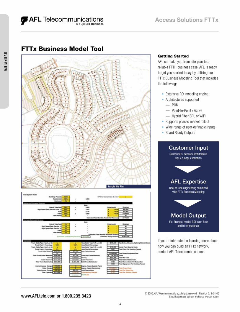
FTTx Business Model Tool
© 2006, AFL Telecommunications, all rights reserved. Revision 0, 9.01.06 Specifications are subject to change without notice.
Getting StartedAFL can take you from site plan to a reliable FTTH business case. AFL is ready to get you started today by utilizing our FTTx Business Modeling Tool that includes the following:
• Extensive ROI modeling engine • Architectures supported — PON — Point-to-Point / Active — Hybrid Fiber BPL or WiFi • Supports phased market rollout • Wide range of user-definable inputs • Board Ready Outputs
If you’re interested in learning more about how you can build an FTTx network, contact AFL Telecommunications.
Customer InputSubscribers, network architecture,
OpEx & CapEx variables
AFL ExpertiseOne-on-one engineering combined
with FTTx Business Modeling
Model OutputFull financial model: ROI, cash flow
and bill of materials
4
OV
ER
VIE
W
5
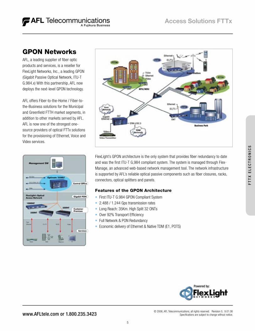
GPON Networks
© 2006, AFL Telecommunications, all rights reserved. Revision 0, 9.01.06 Specifications are subject to change without notice.
Powered by:
AFL, a leading supplier of fiber optic products and services, is a reseller for FlexLight Networks, Inc., a leading GPON (Gigabit Passive Optical Network, ITU-T G.984.x) With this partnership, AFL now deploys the next-level GPON technology.
AFL offers Fiber-to-the-Home / Fiber-to-the-Business solutions for the Municipal and Greenfield FTTH market segments, in addition to other markets served by AFL. AFL is now one of the strongest one-source providers of optical FTTx solutions for the provisioning of Ethernet, Voice and Video services.
FlexLight’s GPON architecture is the only system that provides fiber redundancy to date and was the first ITU-T G,984 compliant system. The system is managed through Flex-Manage, an advanced web-based network management tool. The network infrastructure is supported by AFL’s reliable optical passive components such as fiber closures, racks, connectors, optical splitters and panels.
Features of the GPON Architecture
• First ITU-T G.984 GPON Compliant System• 2.488 / 1.244 Gps transmission rates• Long Reach: 35Km. High Split 32 ONTs• Over 92% Transport Efficiency• Full Network & PON Redundancy• Economic delivery of Ethernet & Native TDM (E1, POTS)
FT
TX
EL
EC
TR
ON
ICS
6
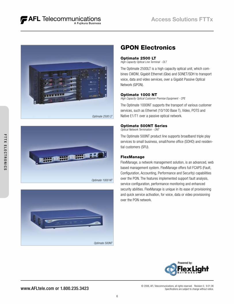
Optimate 2500 LTHigh Capacity Optical Line Terminal - OLT
The Optimate 2500LT is a high capacity optical unit, which com-bines CWDM, Gigabit Ethernet (Gbe) and SONET/SDH to transport voice, data and video services, over a Gigabit Passive Optical Network (GPON).
Optimate 1000 NTHigh Capacity Optical Customer Premise Equipment - CPE
The Optimate 1000NT supports the transport of various customer services, such as Ethernet (10/100 Base T), Video, POTS and Native E1/T1 over a passive optical network.
Optimate 500NT SeriesOptical Network Termination - ONT
The Optimate 500NT product line supports broadband triple play services to small business, small/home office (SOHO) and residen-tial customers (SFU).
FlexManageFlexManage, a network management solution, is an advanced, web based management system. FlexManage offers full FCAPS (Fault, Configuration, Accounting, Performance and Security) capabilities over the PON. The features implemented support fault analysis, service configuration, performance monitoring and enhanced security abilities. FlexManage is unique in its ease of provisioning and quick service activation, for voice, data or video provisioning over the PON network.
Optimate 2500 LT
Optimate 1000 NT
Optimate 500NT
GPON Electronics
Powered by:
© 2006, AFL Telecommunications, all rights reserved. Revision 0, 9.01.06 Specifications are subject to change without notice.
FT
TX
EL
EC
TR
ON
ICS
7
Features
• Supports up to 32 connections over a single fiber within a 20 km radius• Unique non-linear distortion control features to enable RF video overlay while retaining full
compliance with IEEE 802.3ah• Capability to assign bandwidth limits, bandwidth guarantees, and bandwidth burst
capability by subscriber• Ability to support both 802.1q tagged and untagged traffic at the subscriber premise• Stacked VLAN support• Class of Service Prioritization• Redundant and hot-swappable power supply• Full suite of SNMP traps, security and administrative features
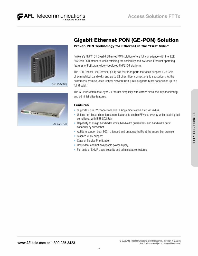
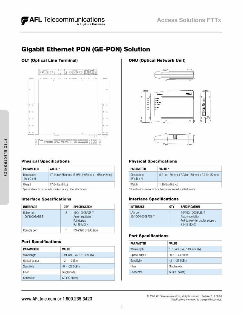
Gigabit Ethernet PON (GE-PON) SolutionProven PON Technology for Ethernet in the “First Mile.”
Fujikura’s FNP4101 Gigabit Ethernet PON solution offers full compliance with the IEEE 802.3ah PON standard while retaining the scalability and switched-Ethernet operating features of Fujikura’s widely-deployed FNP2101 platform.
The 1RU Optical Line Terminal (OLT) has four PON ports that each support 1.25 Gb/s of symmetrical bandwidth and up to 32 direct fiber connections to subscribers. At the customer’s premise, each Optical Network Unit (ONU) supports burst capabilities up to a full Gigabit.
The GE-PON combines Layer-2 Ethernet simplicity with carrier-class security, monitoring, and administrative features.
ONU (FNP6010)
OLT (FNP4101)
© 2006, AFL Telecommunications, all rights reserved. Revision 0, 2.08.06 Specifications are subject to change without notice.
FT
TX
EL
EC
TR
ON
ICS
8
PARAMETER VALUE *
Dimensions (W x D x H)
17.14in (435mm) x 15.96in (405mm) x 1.65in (42mm)
Weight 17.64 lbs (8 kg)
* Specifications do not include brackets or any other attachments.
PARAMETER VALUE *
Dimensions(W x D x H)
5.91in (150mm) x 7.08in (180mm) x 2.04in (52mm)
Weight 1.10 lbs (0.5 kg)
* Specifications do not include brackets or any other attachments.
ONU (Optical Network Unit)OLT (Optical Line Terminal)
Physical Specifications Physical Specifications
Interface Specifications
INTERFACE QTY SPECIFICATION
Uplink port 100/1000BASE-T
2 100/1000BASE-TAuto-negotiationFull duplexRJ-45 MDI-X
Console port 1 RS-232C D-SUB 9pin
Port Specifications
PARAMETER VALUE
Wavelength 1490nm (Tx) / 1310nm (Rx)
Optical output +2 ~ +7dBm
Sensitivity -9 ~ -29.5dBm
Fiber Singlemode
Connector SC (PC polish)
Interface Specifications
INTERFACE QTY SPECIFICATION
LAN port 10/100/1000BASE-T
1 10/100/1000BASE-TAuto-negotiationFull duplex/Half duplex support RJ-45 MDI-X
Port Specifications
PARAMETER VALUE
Wavelength 1310nm (Tx) / 1490nm (Rx)
Optical output -0.5 ~ +4.5dBm
Sensitivity -3 ~ -25.5dBm
Fiber Singlemode
Connector SC (PC polish)
Gigabit Ethernet PON (GE-PON) Solution
© 2006, AFL Telecommunications, all rights reserved. Revision 0, 2.08.06 Specifications are subject to change without notice.
FT
TX
EL
EC
TR
ON
ICS
9
Features
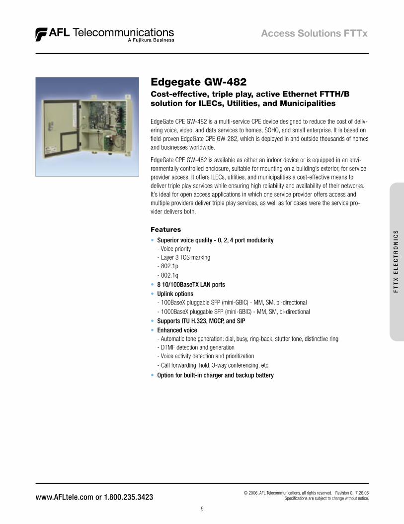
• Superior voice quality - 0, 2, 4 port modularity - Voice priority - Layer 3 TOS marking - 802.1p - 802.1q• 8 10/100BaseTX LAN ports • Uplink options - 100BaseX pluggable SFP (mini-GBIC) - MM, SM, bi-directional - 1000BaseX pluggable SFP (mini-GBIC) - MM, SM, bi-directional• Supports ITU H.323, MGCP, and SIP • Enhanced voice - Automatic tone generation: dial, busy, ring-back, stutter tone, distinctive ring - DTMF detection and generation - Voice activity detection and prioritization - Call forwarding, hold, 3-way conferencing, etc.
• Option for built-in charger and backup battery
Edgegate GW-482Cost-effective, triple play, active Ethernet FTTH/B solution for ILECs, Utilities, and Municipalities
EdgeGate CPE GW-482 is a multi-service CPE device designed to reduce the cost of deliv-ering voice, video, and data services to homes, SOHO, and small enterprise. It is based on field-proven EdgeGate CPE GW-282, which is deployed in and outside thousands of homes and businesses worldwide.
EdgeGate CPE GW-482 is available as either an indoor device or is equipped in an envi-ronmentally controlled enclosure, suitable for mounting on a building’s exterior, for service provider access. It offers ILECs, utilities, and municipalities a cost-effective means to deliver triple play services while ensuring high reliability and availability of their networks. It’s ideal for open access applications in which one service provider offers access and multiple providers deliver triple play services, as well as for cases were the service pro-vider delivers both.
© 2006, AFL Telecommunications, all rights reserved. Revision 0, 7.26.06 Specifications are subject to change without notice.
FT
TX
EL
EC
TR
ON
ICS
10
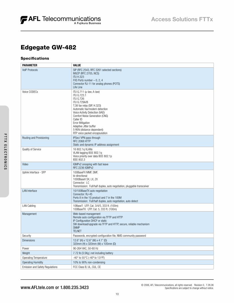
Specifications
PARAMETER VALUE
VoIP Protocols SIP (RFC 2543, RFC 3261 selected sections)MGCP (RFC 2705, NCS)ITU H.323FXS Ports number – 0, 2, 4Connector RJ-11 for analog phones (POTS)Life Line
Voice CODECs ITU G.711 (µ-law, A-law)ITU G.723.1ITU G.726ITU G.729A/BT.38 fax relay (SIP, H.323)Automatic fax/modem detectionVoice Activity Detection (VAD)Comfort Noise Generation (CNG)Caller IDError MitigationAdaptive Jitter buffer5 REN (distance dependent)RTP voice packet encapsulation
Routing and Provisioning IPSec/ VPN pass-throughRFC 2068 HTTPStatic and dynamic IP address assignment
Quality of Service 16 802.1q VLANsVLAN tagging IEEE 802.1qVoice priority over data IEEE 802.1pIEEE 802.3
Video IGMPv2 snooping with fast leaveRFC 2236 IGMPv2
Uplink Interface - SFP 100BaseFX MMF, SMF,bi-directional1000BaseX SX, LX, ZXConnector: LCTransmission: Full/half duplex, auto negotiation, pluggable transceiver
LAN Interface 10/100BaseTX auto negotiationConnector: RJ-45Ports 8 in the 1G product and 7 in the 100MTransmission: Full/half duplex, auto negotiation, auto detect
LAN Cabling 10BaseT: UTP, Cat. 3/4/5, 333 ft. (100m)100BaseTX: UTP, Cat. 5, 333 ft. (100m)
Management Web-based managementRemote auto configuration via TFTP and HTTPIP Configuration DHCP or staticSW download/upgrade via TFTP and HTTP, secure, reliable mechanismSNMPTELNET
Security Passwords, encrypted configuration file, NMS community password
Dimensions 12.6” (H) x 12.6” (W) x 4.1” (D)320mm (H) x 320mm (W) x 105mm (D)
Power 90-264 VAC, 50-60 Hz
Weight 7.72 lb (3.5Kg ) not including battery
Operating Temperature -40° to 55°C (-40º to 131ºF)
Operating Humidity 10% to 90% non-condensing
Emission and Safety Regulations FCC Class B, UL, CUL, CE
Edgegate GW-482
© 2006, AFL Telecommunications, all rights reserved. Revision 0, 7.26.06 Specifications are subject to change without notice.
FT
TX
EL
EC
TR
ON
ICS
11
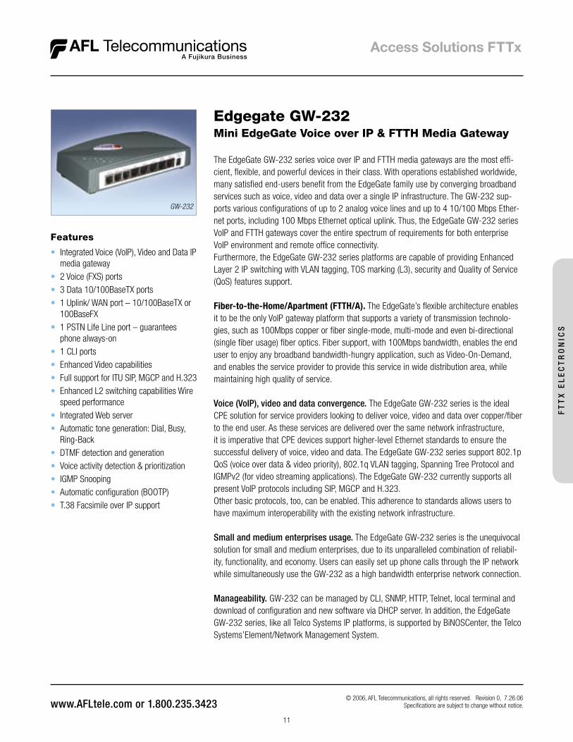
Features
• Integrated Voice (VoIP), Video and Data IP media gateway
• 2 Voice (FXS) ports • 3 Data 10/100BaseTX ports • 1 Uplink/ WAN port – 10/100BaseTX or
100BaseFX • 1 PSTN Life Line port – guarantees
phone always-on • 1 CLI ports • Enhanced Video capabilities • Full support for ITU SIP, MGCP and H.323 • Enhanced L2 switching capabilities Wire
speed performance • Integrated Web server • Automatic tone generation: Dial, Busy,
Ring-Back • DTMF detection and generation • Voice activity detection & prioritization • IGMP Snooping • Automatic configuration (BOOTP) • T.38 Facsimile over IP support
Edgegate GW-232Mini EdgeGate Voice over IP & FTTH Media Gateway
The EdgeGate GW-232 series voice over IP and FTTH media gateways are the most effi-cient, flexible, and powerful devices in their class. With operations established worldwide, many satisfied end-users benefit from the EdgeGate family use by converging broadband services such as voice, video and data over a single IP infrastructure. The GW-232 sup-ports various configurations of up to 2 analog voice lines and up to 4 10/100 Mbps Ether-net ports, including 100 Mbps Ethernet optical uplink. Thus, the EdgeGate GW-232 series VoIP and FTTH gateways cover the entire spectrum of requirements for both enterprise VoIP environment and remote office connectivity. Furthermore, the EdgeGate GW-232 series platforms are capable of providing Enhanced Layer 2 IP switching with VLAN tagging, TOS marking (L3), security and Quality of Service (QoS) features support.
Fiber-to-the-Home/Apartment (FTTH/A). The EdgeGate’s flexible architecture enables it to be the only VoIP gateway platform that supports a variety of transmission technolo-gies, such as 100Mbps copper or fiber single-mode, multi-mode and even bi-directional (single fiber usage) fiber optics. Fiber support, with 100Mbps bandwidth, enables the end user to enjoy any broadband bandwidth-hungry application, such as Video-On-Demand, and enables the service provider to provide this service in wide distribution area, while maintaining high quality of service.
Voice (VoIP), video and data convergence. The EdgeGate GW-232 series is the ideal CPE solution for service providers looking to deliver voice, video and data over copper/fiber to the end user. As these services are delivered over the same network infrastructure, it is imperative that CPE devices support higher-level Ethernet standards to ensure the successful delivery of voice, video and data. The EdgeGate GW-232 series support 802.1p QoS (voice over data & video priority), 802.1q VLAN tagging, Spanning Tree Protocol and IGMPv2 (for video streaming applications). The EdgeGate GW-232 currently supports all present VoIP protocols including SIP, MGCP and H.323. Other basic protocols, too, can be enabled. This adherence to standards allows users to have maximum interoperability with the existing network infrastructure.
Small and medium enterprises usage. The EdgeGate GW-232 series is the unequivocal solution for small and medium enterprises, due to its unparalleled combination of reliabil-ity, functionality, and economy. Users can easily set up phone calls through the IP network while simultaneously use the GW-232 as a high bandwidth enterprise network connection.
Manageability. GW-232 can be managed by CLI, SNMP, HTTP, Telnet, local terminal and download of configuration and new software via DHCP server. In addition, the EdgeGate GW-232 series, like all Telco Systems IP platforms, is supported by BiNOSCenter, the Telco Systems’Element/Network Management System.
GW-232
© 2006, AFL Telecommunications, all rights reserved. Revision 0, 7.26.06 Specifications are subject to change without notice.
FT
TX
EL
EC
TR
ON
ICS
12
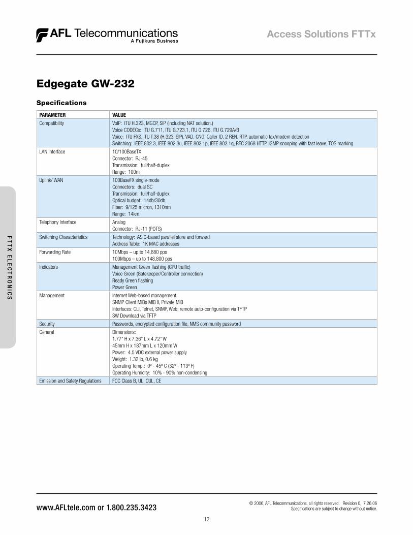
Specifications
PARAMETER VALUE
Compatibility VoIP: ITU H.323, MGCP, SIP (including NAT solution.)Voice CODECs: ITU G.711, ITU G.723.1, ITU G.726, ITU G.729A/BVoice: ITU FXS, ITU T.38 (H.323, SIP), VAD, CNG, Caller ID, 2 REN, RTP, automatic fax/modem detectionSwitching: IEEE 802.3, IEEE 802.3u, IEEE 802.1p, IEEE 802.1q, RFC 2068 HTTP, IGMP snooping with fast leave, TOS marking
LAN Interface 10/100BaseTXConnector: RJ-45Transmission: full/half-duplexRange: 100m
Uplink/ WAN 100BaseFX single-modeConnectors: dual SCTransmission: full/half-duplexOptical budget: 14db/30dbFiber: 9/125 micron, 1310nmRange: 14km
Telephony Interface AnalogConnector: RJ-11 (POTS)
Switching Characteristics Technology: ASIC-based parallel store and forwardAddress Table: 1K MAC addresses
Forwarding Rate 10Mbps – up to 14,880 pps100Mbps – up to 148,800 pps
Indicators Management Green flashing (CPU traffic)Voice Green (Gatekeeper/Controller connection)Ready Green flashingPower Green
Management Internet Web-based managementSNMP Client MIBs MIB II, Private MIBInterfaces: CLI, Telnet, SNMP, Web; remote auto-configuration via TFTPSW Download via TFTP
Security Passwords, encrypted configuration file, NMS community password
General Dimensions:1.77” H x 7.36” L x 4.72” W45mm H x 187mm L x 120mm WPower: 4.5 VDC external power supplyWeight: 1.32 lb, 0.6 kgOperating Temp.: 0º - 45º C (32º - 113º F)Operating Humidity: 10% - 90% non-condensing
Emission and Safety Regulations FCC Class B, UL, CUL, CE
Edgegate GW-232
© 2006, AFL Telecommunications, all rights reserved. Revision 0, 7.26.06 Specifications are subject to change without notice.
FT
TX
EL
EC
TR
ON
ICS
13
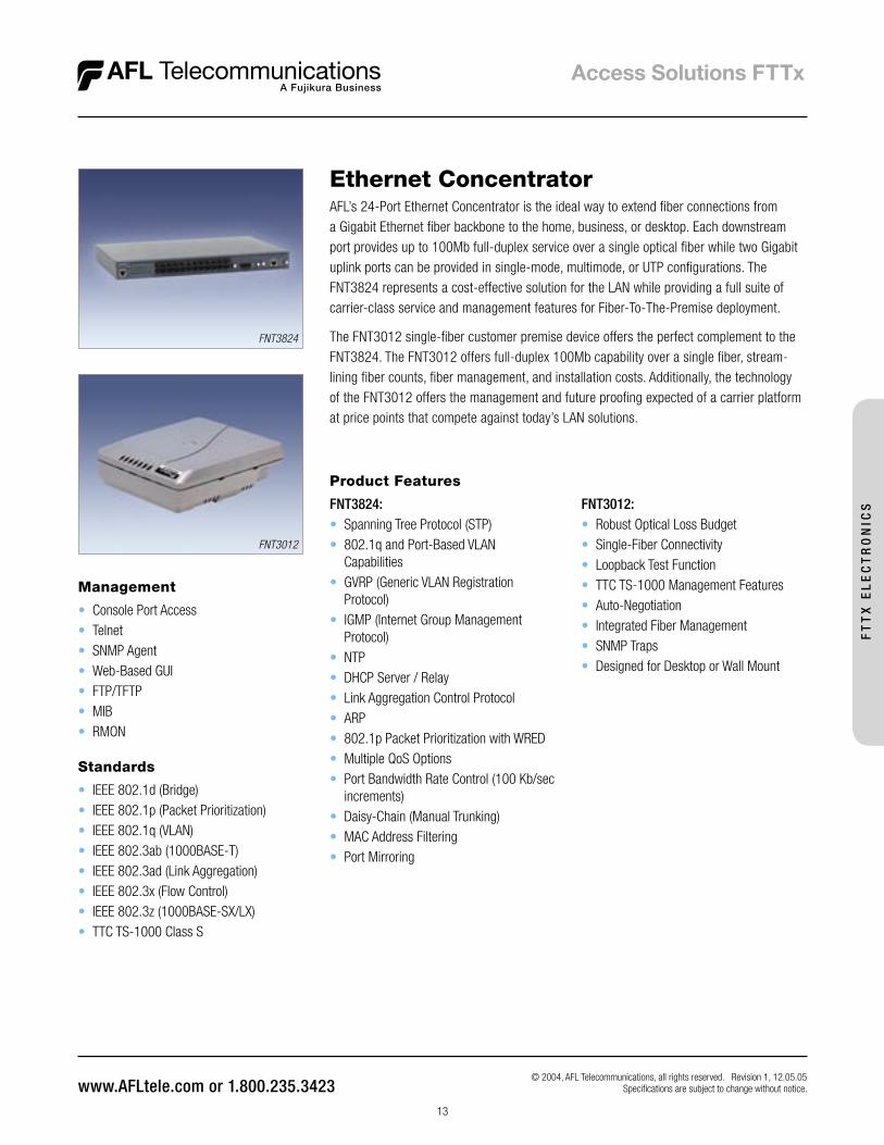
Standards
• IEEE 802.1d (Bridge)• IEEE 802.1p (Packet Prioritization)• IEEE 802.1q (VLAN)• IEEE 802.3ab (1000BASE-T)• IEEE 802.3ad (Link Aggregation)• IEEE 802.3x (Flow Control)• IEEE 802.3z (1000BASE-SX/LX)• TTC TS-1000 Class S
Management
• Console Port Access• Telnet • SNMP Agent• Web-Based GUI• FTP/TFTP• MIB• RMON
Product Features
FNT3824:• Spanning Tree Protocol (STP)• 802.1q and Port-Based VLAN
Capabilities• GVRP (Generic VLAN Registration
Protocol)• IGMP (Internet Group Management
Protocol)• NTP • DHCP Server / Relay• Link Aggregation Control Protocol• ARP• 802.1p Packet Prioritization with WRED• Multiple QoS Options• Port Bandwidth Rate Control (100 Kb/sec
increments)• Daisy-Chain (Manual Trunking)• MAC Address Filtering• Port Mirroring
Ethernet Concentrator AFL’s 24-Port Ethernet Concentrator is the ideal way to extend fiber connections from a Gigabit Ethernet fiber backbone to the home, business, or desktop. Each downstream port provides up to 100Mb full-duplex service over a single optical fiber while two Gigabit uplink ports can be provided in single-mode, multimode, or UTP configurations. The FNT3824 represents a cost-effective solution for the LAN while providing a full suite of carrier-class service and management features for Fiber-To-The-Premise deployment.
The FNT3012 single-fiber customer premise device offers the perfect complement to the FNT3824. The FNT3012 offers full-duplex 100Mb capability over a single fiber, stream-lining fiber counts, fiber management, and installation costs. Additionally, the technology of the FNT3012 offers the management and future proofing expected of a carrier platform at price points that compete against today’s LAN solutions.
FNT3824
FNT3012
© 2004, AFL Telecommunications, all rights reserved. Revision 1, 12.05.05 Specifications are subject to change without notice.
FNT3012:• Robust Optical Loss Budget• Single-Fiber Connectivity• Loopback Test Function• TTC TS-1000 Management Features • Auto-Negotiation• Integrated Fiber Management• SNMP Traps• Designed for Desktop or Wall Mount
FT
TX
EL
EC
TR
ON
ICS
14
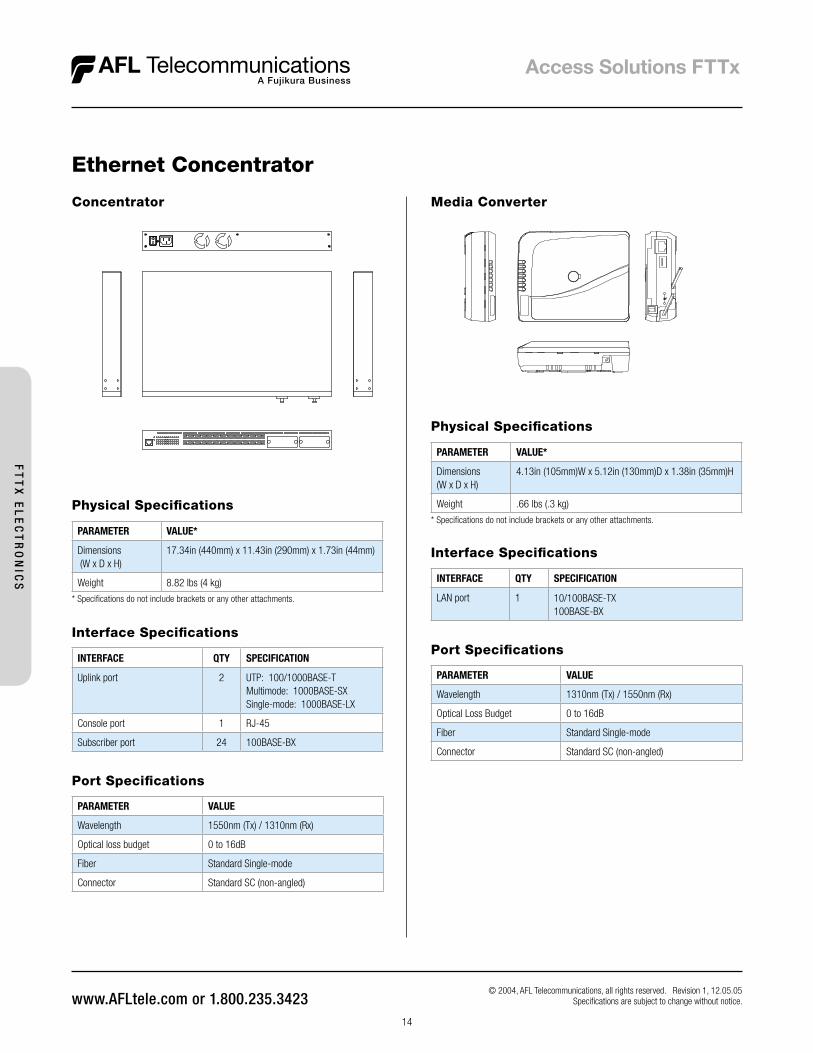
PARAMETER VALUE*
Dimensions (W x D x H)
17.34in (440mm) x 11.43in (290mm) x 1.73in (44mm)
Weight 8.82 lbs (4 kg)
* Specifications do not include brackets or any other attachments.
PARAMETER VALUE*
Dimensions(W x D x H)
4.13in (105mm)W x 5.12in (130mm)D x 1.38in (35mm)H
Weight .66 lbs (.3 kg)
* Specifications do not include brackets or any other attachments.
Media ConverterConcentrator
Physical Specifications
Physical Specifications
Interface Specifications
INTERFACE QTY SPECIFICATION
Uplink port 2 UTP: 100/1000BASE-TMultimode: 1000BASE-SXSingle-mode: 1000BASE-LX
Console port 1 RJ-45
Subscriber port 24 100BASE-BX
Interface Specifications
INTERFACE QTY SPECIFICATION
LAN port 1 10/100BASE-TX100BASE-BX
Port Specifications
PARAMETER VALUE
Wavelength 1310nm (Tx) / 1550nm (Rx)
Optical Loss Budget 0 to 16dB
Fiber Standard Single-mode
Connector Standard SC (non-angled)
Ethernet Concentrator
© 2004, AFL Telecommunications, all rights reserved. Revision 1, 12.05.05 Specifications are subject to change without notice.
Port Specifications
PARAMETER VALUE
Wavelength 1550nm (Tx) / 1310nm (Rx)
Optical loss budget 0 to 16dB
Fiber Standard Single-mode
Connector Standard SC (non-angled)
FT
TX
EL
EC
TR
ON
ICS
© 2006, AFL Telecommunications, all rights reserved. Revision 0, 9.01.06 Specifi cations are subject to change without notice.
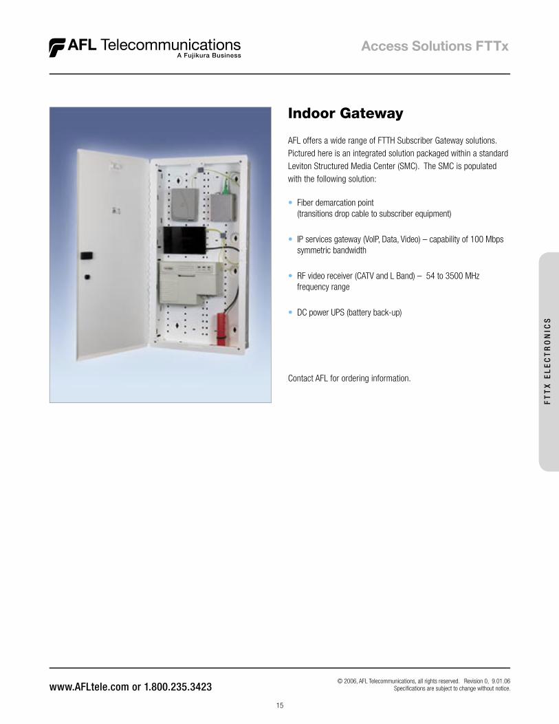
Indoor Gateway
AFL offers a wide range of FTTH Subscriber Gateway solutions. Pictured here is an integrated solution packaged within a standard Leviton Structured Media Center (SMC). The SMC is populated with the following solution:
• Fiber demarcation point (transitions drop cable to subscriber equipment)
• IP services gateway (VoIP, Data, Video) – capability of 100 Mbps symmetric bandwidth
• RF video receiver (CATV and L Band) – 54 to 3500 MHz frequency range
• DC power UPS (battery back-up)
Contact AFL for ordering information.
15
FT
TX
EL
EC
TR
ON
ICS

16
© 2004, AFL Telecommunications, all rights reserved. Revision 1, 12.05.05 Specifications are subject to change without notice.
Measuring less than 3.5 inches deep and 2 inches wide, IMC Networks’ MiniMc is the smallest media converter in the industry which has both data connections on the same side of the unit, and MiniMc is a fraction of the cost of other alternatives. In addition, plug-and-play operation, three model types and various power options make the MiniMc series of miniature media converters easy and convenient to use.
Powered by:
Networks
The iMediaChassis series is an intelligent, carrier-grade optical access platform that supports Ethernet, ATM/SONET, T1/E1, DS3/E3 and WDM networking technologies. The iMediaChassis series enables network campus operators and service providers to reduce the capital and operational expenses by providing all copper-to-fiber and multi-mode to single-mode conversions, network distance extensions and Transparent LAN services from the same chassis platform. Installed at the Central Office or the Point-of-Presence, the iMediaChassis/20 supports carrier requirements for the Operations, Administration, Maintenance and Provisioning of Metro Ethernet services.
iMediaChassisSNMP Manageable Fiber Connectivity Platform
MiniMc10/100 Gig Switching and Gigabit Miniature Media Converters
Cost-effective, space-saving and flexible, the MiniMc series of miniature media converters proves once again that the company that invented media convert-ers continues to develop the best.
The iMediaChassis series includes:• 6-slot (1U high) and 20-slot (3U high) models for installing iMcV series modules• An additional chassis slot for an optional SNMP management module
FT
TX
EL
EC
TR
ON
ICS
The MiniMc series includes:• MiniMc TP-TX/FX: Switching converter; 10/100 auto-negotiation
on the twisted pair port while the fiber port operates at 100 Mbps Fast Ethernet full duplex
• IE-MiniMc TP-TX/FX: This Industrial Ethernet model is the same as the switching converter listed above, with additional features, including: an operating temperature of up to 70° C, a 4-termi-nal DC power block which has an extended voltage range (5 to 50VDC), DIN-rail mounting capability, and compliance with the IEEE 802.3af Power over Ethernet standard
• MiniMc-Gigabit: 1.25 Gbps twisted pair conversion to 1.25 Gbps fiber (non-switching)
• Giga-MiniMc: 10/100/1000 Mbps Gigabit Fiber Converter
Reliable and flexible, the iMediaChassis/20 has the highest port density of any modular, intelligent, carrier-class optical access platform in the industry.
The MiniMc Industrial series includes:• AC and DC power options• Extended voltage range on the DC power block: 5 to 50 VDC input• Extended operating temperature of -25°C to +70°C• DIN clips for mounting on a DIN rail• Compliance with IEEE 802.3af Power over Ethernet standard
(IE-MiniMc only)
17
© 2004, AFL Telecommunications, all rights reserved. Revision 1, 12.05.05 Specifications are subject to change without notice.
Powered by:
Networks
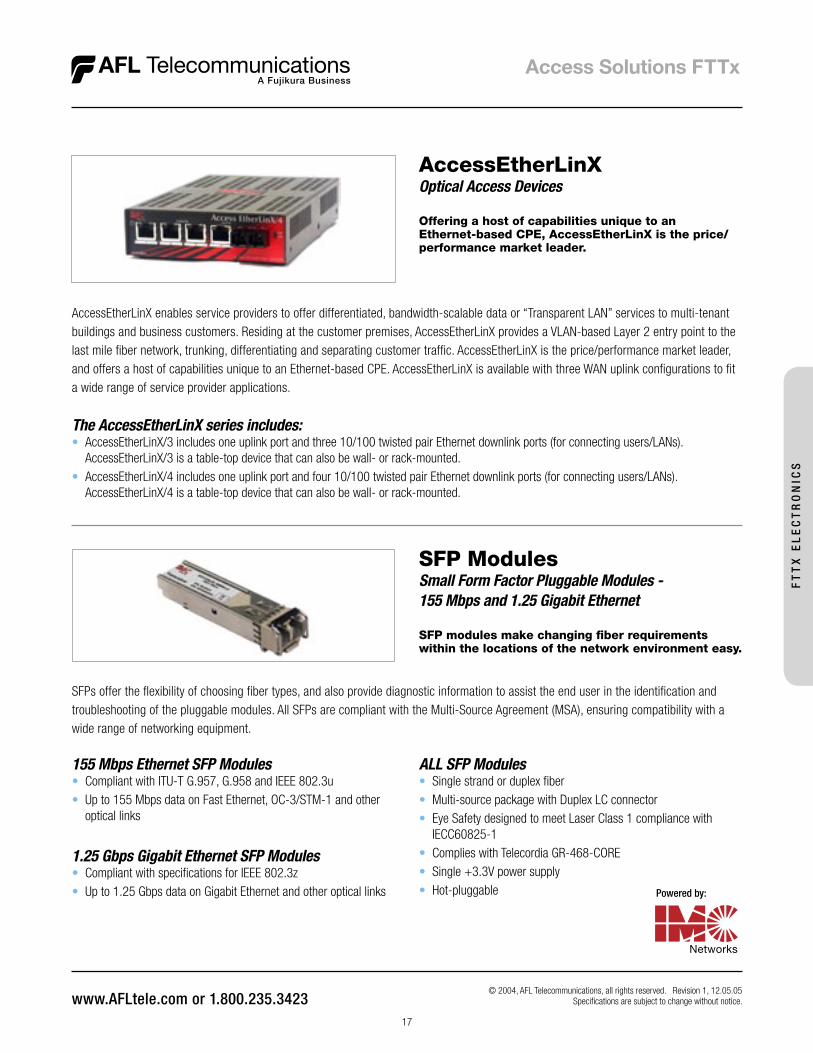
AccessEtherLinXOptical Access Devices
Offering a host of capabilities unique to an Ethernet-based CPE, AccessEtherLinX is the price/performance market leader.
AccessEtherLinX enables service providers to offer differentiated, bandwidth-scalable data or “Transparent LAN” services to multi-tenant buildings and business customers. Residing at the customer premises, AccessEtherLinX provides a VLAN-based Layer 2 entry point to the last mile fiber network, trunking, differentiating and separating customer traffic. AccessEtherLinX is the price/performance market leader, and offers a host of capabilities unique to an Ethernet-based CPE. AccessEtherLinX is available with three WAN uplink configurations to fit a wide range of service provider applications.
The AccessEtherLinX series includes:• AccessEtherLinX/3 includes one uplink port and three 10/100 twisted pair Ethernet downlink ports (for connecting users/LANs).
AccessEtherLinX/3 is a table-top device that can also be wall- or rack-mounted.• AccessEtherLinX/4 includes one uplink port and four 10/100 twisted pair Ethernet downlink ports (for connecting users/LANs).
AccessEtherLinX/4 is a table-top device that can also be wall- or rack-mounted.
FT
TX
EL
EC
TR
ON
ICS
SFP ModulesSmall Form Factor Pluggable Modules - 155 Mbps and 1.25 Gigabit Ethernet
SFP modules make changing fiber requirements within the locations of the network environment easy.
SFPs offer the flexibility of choosing fiber types, and also provide diagnostic information to assist the end user in the identification and troubleshooting of the pluggable modules. All SFPs are compliant with the Multi-Source Agreement (MSA), ensuring compatibility with a wide range of networking equipment.
155 Mbps Ethernet SFP Modules• Compliant with ITU-T G.957, G.958 and IEEE 802.3u• Up to 155 Mbps data on Fast Ethernet, OC-3/STM-1 and other
optical links
1.25 Gbps Gigabit Ethernet SFP Modules• Compliant with specifications for IEEE 802.3z• Up to 1.25 Gbps data on Gigabit Ethernet and other optical links
ALL SFP Modules• Single strand or duplex fiber• Multi-source package with Duplex LC connector• Eye Safety designed to meet Laser Class 1 compliance with
IECC60825-1• Complies with Telecordia GR-468-CORE• Single +3.3V power supply• Hot-pluggable
© 2006, AFL Telecommunications, all rights reserved. Revision 0, 9.01.06 Specifi cations are subject to change without notice.
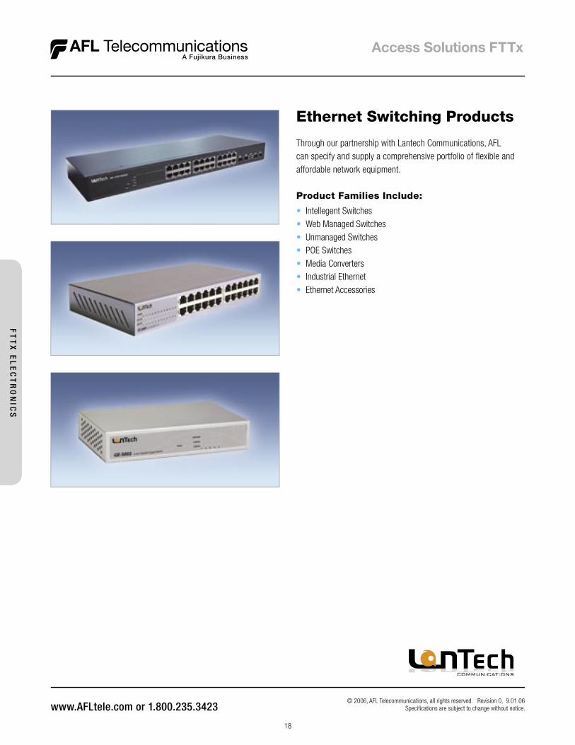
Through our partnership with Lantech Communications, AFL can specify and supply a comprehensive portfolio of fl exible and affordable network equipment.
Product Families Include:
• Intellegent Switches• Web Managed Switches• Unmanaged Switches• POE Switches• Media Converters• Industrial Ethernet• Ethernet Accessories
Ethernet Switching Products
18
FT
TX
EL
EC
TR
ON
ICS
© 2006, AFL Telecommunications, all rights reserved. Revision 0, 9.01.06 Specifications are subject to change without notice.
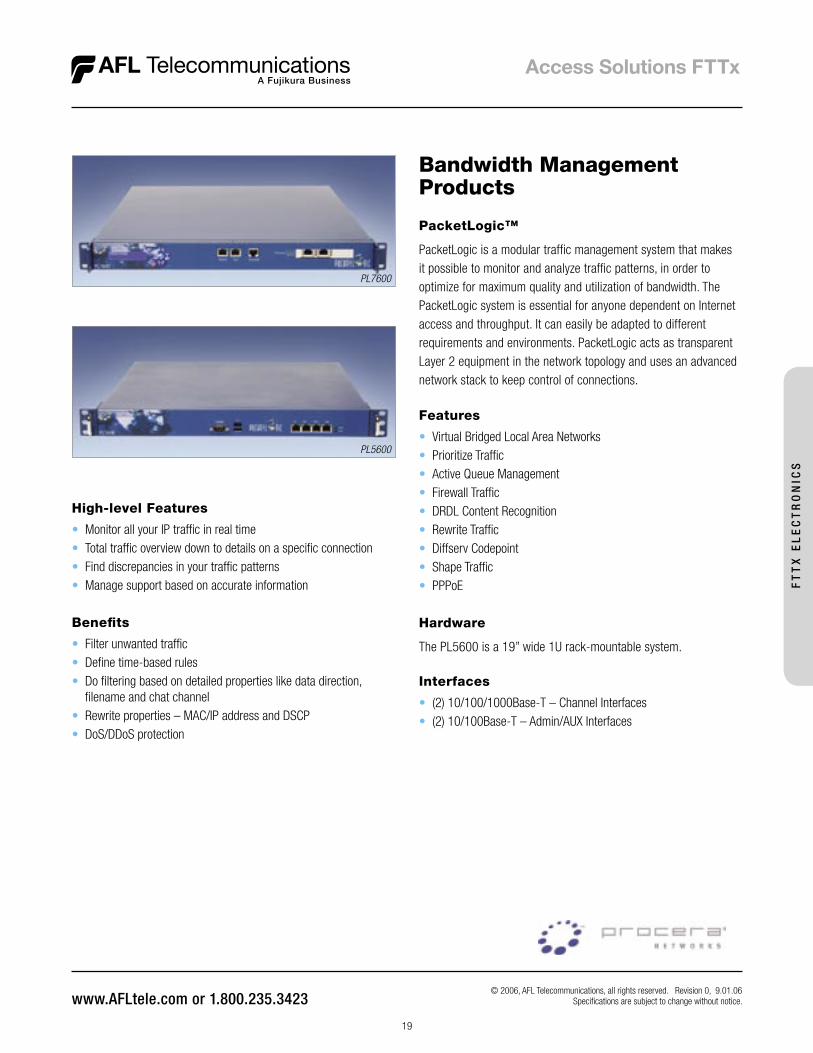
Bandwidth ManagementProducts
Features
• Virtual Bridged Local Area Networks• Prioritize Traffic• Active Queue Management• Firewall Traffic• DRDL Content Recognition• Rewrite Traffic• Diffserv Codepoint• Shape Traffic• PPPoE
Hardware
The PL5600 is a 19” wide 1U rack-mountable system.
Interfaces
• (2) 10/100/1000Base-T – Channel Interfaces• (2) 10/100Base-T – Admin/AUX Interfaces
PacketLogic™
PacketLogic is a modular traffic management system that makes it possible to monitor and analyze traffic patterns, in order to optimize for maximum quality and utilization of bandwidth. The PacketLogic system is essential for anyone dependent on Internet access and throughput. It can easily be adapted to different requirements and environments. PacketLogic acts as transparent Layer 2 equipment in the network topology and uses an advanced network stack to keep control of connections.
19
High-level Features
• Monitor all your IP traffic in real time• Total traffic overview down to details on a specific connection• Find discrepancies in your traffic patterns• Manage support based on accurate information
Benefits
• Filter unwanted traffic• Define time-based rules• Do filtering based on detailed properties like data direction,
filename and chat channel• Rewrite properties – MAC/IP address and DSCP• DoS/DDoS protection
FT
TX
EL
EC
TR
ON
ICS
PL7600
PL5600
© 2006, AFL Telecommunications, all rights reserved. Revision 0, 9.01.06 Specifi cations are subject to change without notice.
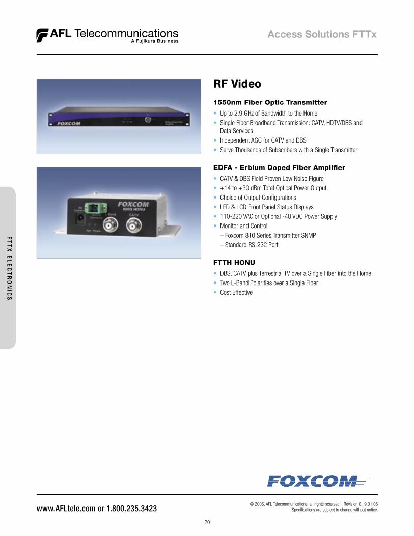
RF Video
1550nm Fiber Optic Transmitter
• Up to 2.9 GHz of Bandwidth to the Home• Single Fiber Broadband Transmission: CATV, HDTV/DBS and
Data Services• Independent AGC for CATV and DBS• Serve Thousands of Subscribers with a Single Transmitter
EDFA - Erbium Doped Fiber Amplifi er
• CATV & DBS Field Proven Low Noise Figure• +14 to +30 dBm Total Optical Power Output• Choice of Output Confi gurations• LED & LCD Front Panel Status Displays• 110-220 VAC or Optional -48 VDC Power Supply• Monitor and Control – Foxcom 810 Series Transmitter SNMP – Standard RS-232 Port
FTTH HONU
• DBS, CATV plus Terrestrial TV over a Single Fiber into the Home• Two L-Band Polarities over a Single Fiber• Cost Effective
20
FT
TX
EL
EC
TR
ON
ICS

21
The Future Access™ Fiber Distribution Hub (FDH) is designed to provide a local conver-gence point in the Outside Plant environment, housing optical splitters that link feeder cables from the CO to distribution cables serving customer premises. Its compact size and modular-based platform aid in installation efficiency, while keeping initial deployment costs down. This modular approach allows a service provider to incrementally grow the FDH as their take rate increases. Distribution modules are available in 72-port configura-tions, providing the option of incrementally populating the FDH at the onset of deployment. This results in immediate cost savings to the service provider since distribution and splitter modules can be installed as paying customers take the offered services.
Future Access™ FDH-100Fiber Distribution Hub
© 2006, AFL Telecommunications, all rights reserved. Revision 0, 9.25.06 Specifications are subject to change without notice.
Features
• Modular distribution platform allows for incremental deployment costs and immediate cost savings
• Small Size is unobtrusive in residential deployments
• Enhanced fiber management provides simplified routing and termination of fiber pigtails
• Dual-door entry allows easy access to distribution and fiber management fields
• Flexible pad, pole, and optional post mounting options for deployment in the most convenient location
Specifications
PARAMETER
VALUE
72 / 144 / 216 / 288 FIBER 360 / 432 FIBER
Configuration Pad, Pole, or Post* Mount Pad, Pole, or Post* Mount
Height (pole mount) 26” 33”
Height (pad mount) 38” 45”
Dimension (W x D) 20” x 20” 20” x 20”
Connector Type SC-APC SC-APC
Cable Type Loose Tube or Ribbon Loose Tube or Ribbon
Splitter Module Capacity 9 Modules 14 Modules
Parking Lot Capacity 64 128
Color Standard Electric Ivory Standard Electric Ivory
PA
SS
IVE
IN
FR
AS
TR
UC
TU
RE
Ordering InformationFDH100 Units
PART NUMBER DESCRIPTIONAll models feature: 100 foot preterminated loose tube cable stubs (input/output), SC-APC adapters, ground skirt, no splitters.
FD000207 FDH100, 72F Pad Mount
FD000204 FDH100, 144F Pad Mount
FD000205 FDH100, 216F Pad Mount
FD000201 FDH100, 288F Pad Mount
FD000202 FDH100, 288F Pole Mount
FD000223 FDH100, 360F Pad Mount
FD000221 FDH100, 432F Pad Mount
FD000222 FDH100, 432F Pole Mount
Accessories
PART NUMBER DESCRIPTION
FD000097 Additional 12” Mounting Skirt for Pad Mount FDH (All Cabinet Sizes)
FD000158 Hand-hole, Split lid design, 60”L x 36”W x 24”D, HDPE Structural Foam, Stainless Hardware, Green
FD000039 1x32 Future Access Splitter Module, Bend Insensitive Pigtails, Parking Lots, SC-APC connectors
FD000092 2x32 Future Access Splitter Module, Bend Insensitive Pigtails, Parking Lots, SC-APC connectors
FD000160 1x16 Future Access Splitter Module, Bend Insensitive Pigtails, Parking Lots, SC-APC connectors
FD000161 2x16 Future Access Splitter Module, Bend Insensitive Pigtails, Parking Lots, SC-APC connectors
FD000162 Dual 1x16 Future Access Splitter Module, Bend Insensitive Pigtails, Parking Lots, SC-APC connectors
22
© 2002-2006, AFL Telecommunications, all rights reserved. Revision 0, 9.1.06 Specifications are subject to change without notice.
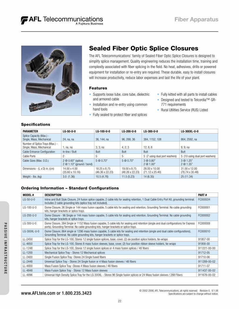
The AFL Telecommunications’ family of Sealed Fiber Optic Splice Closures is designed to simplify splice management. Quality engineering reduces the installation time, training and complexity associated with fiber splicing in the field. No heat, adhesives, drills or powered equipment for installation or re-entry are required. These durable, easy to install closures will increase productivity, reduce labor expenses and last the life of your plant.
Sealed Fiber Optic Splice Closures
Features
• Supports loose tube, core tube, dielectric and armored cable
• Installation and re-entry using common hand tools
• Fully sealed to protect fiber and splices
Specifications
PARAMETER LG-50-U-0 LG-100-U-0 LG-200-U-0 LG-300-U-0 LG-300XL-U-0Splice Capacity (Max.) - Single, Mass, Mechanical 24, na, na 36, 144, na 96, 288, 36 384, 1152, 108 864, 2592, na
Number of Splice Trays (Max.) - Single, Mass, Mechanical 1, na, na 3, 3, na 4, 2, 3 12, 8, 8 9, 9, na
Cable Entrance Configuration In-line / Butt Butt Butt Butt Butt
Cable Ports 2 5 5 5 (7 using dual port washers) 5 (10 using dual port washers)
Cable Sizes (Max. O.D.) 2 @ 0.60" (splice)2 @ 1.10" (ground / bond)
5 @ 0.70" 5 @ 0.70" 3 @ 0.80"2 @ 1.00"
3 @ 1.25”2 @ 1.35”
Dimensions - (L x D) in. (cm) 14.00 x 4.00 (35.60 x 10.16)
18.25 x 8.75(46.36 x 22.23)
19.00 x 8.75(48.26 x 22.23)
28.00 x 10.00(71.12 x 25.40)
31.00 x 12.00(78.74 x 30.48)
Weight - lbs. (kg) 3.0 (1.36) 10.5 (4.76) 11.5 (5.23) 14 (6.35) 25 (11.34)
Ordering Information – Standard Configurations
MODEL # DESCRIPTION PART #LG-50-U-0 Inline and Butt Style Closure, 24 fusion splice capable, 2 cable kits for sealing retention, 1 Dual Cable Entry Port Kit, grounding terminal.
Includes 2 cable grounding kits (splice tray not included).FC000034
LG-100-U-0 Dome Closure, 36 Single or 144 mass fusion capable, 5 cable kits for sealing and retention, Grounding Terminal. No cable grounding kits, hanger brackets or splice trays.
FC000001
LG-200-U-0 Dome Closure - 96 Single or 144 mass fusion capable, 5 cable kits for sealing and retention, Grounding Terminal. No cable grounding kits, hanger brackets or splice trays.
FC000002
LG-300-U-0 Dome Closure, 384 Single or 1152 Mass fusion capable, 5 cable kits for sealing and retention (single and dual configurations for Express ports), Grounding Terminal. No cable grounding kits, hanger brackets or splice trays.
FC000009
LG-300XL-U-0 Dome Closure, 864 single or 1296 mass fusion capable, 5 cable kits for sealing and retention (single and dual cable configurations), Grounding Terminal. No cable grounding kits, hanger brackets or splice trays.
FC000010
LL-2450 Splice Tray for the LG-100, Stores 12 single fusion splices, base, cover, (2) six position splice holders, tie-wraps 91957-00
LL-4850 Splice Tray for the LG-100, Stores 8 mass fusion sleeves, base, cover, (2) four position ribbon sleeve holders, tie-wraps 91958-00
LL-1248 Splice Tray for the LG-100, Stores 12 single fusion splices or 4 mass fusion splices / 48 fibers 911221-00-00
LL-1200 Mechanical Splice Tray - Stores 12 Mechanical splices 91712-05
LL-2400 Single Fusion Splice Tray -Stores 24 Single fused fibers 91710-06
LL-2448 Universal Splice Tray - Stores 24 Single fusion or 4 Mass fusion sleeves / 48 fibers 911289-00-02
LL-4800 Mass Fusion Splice Tray -Stores 4 Mass fusion sleeves / 48 fibers 91711-07
LL-4848 Mass Fusion Splice Tray - Stores 12 Mass fusion sleeves 911437-00-02
LL-4896 Universal High Density Splice Tray for the LG-300XL - Stores 96 Single fusion splices or 24 Mass fusion sleeves / 288 Fibers 911676-00-02
• Fully kitted with all parts to install cables• Designed and tested to Telcordia™ GR-
771 requirements• Rural Utilities Service (RUS) Listed
PA
SS
IVE
INF
RA
ST
RU
CT
UR
E
23
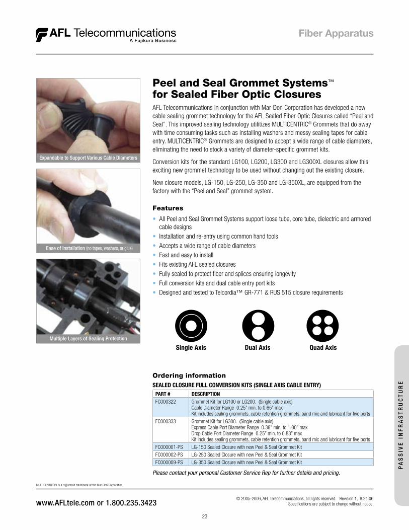
Peel and Seal Grommet Systems™ for Sealed Fiber Optic Closures
Features
• All Peel and Seal Grommet Systems support loose tube, core tube, dielectric and armored cable designs
• Installation and re-entry using common hand tools• Accepts a wide range of cable diameters• Fast and easy to install• Fits existing AFL sealed closures• Fully sealed to protect fiber and splices ensuring longevity• Full conversion kits and dual cable entry port kits• Designed and tested to Telcordia™ GR-771 & RUS 515 closure requirements
AFL Telecommunications in conjunction with Mar-Don Corporation has developed a new cable sealing grommet technology for the AFL Sealed Fiber Optic Closures called “Peel and Seal”. This improved sealing technology utilitizes MULTICENTRIC® Grommets that do away with time consuming tasks such as installing washers and messy sealing tapes for cable entry. MULTICENTRIC® Grommets are designed to accept a wide range of cable diameters, eliminating the need to stock a variety of diameter-specific grommet kits.
Conversion kits for the standard LG100, LG200, LG300 and LG300XL closures allow this exciting new grommet technology to be used without changing out the existing closure.
New closure models, LG-150, LG-250, LG-350 and LG-350XL, are equipped from the factory with the “Peel and Seal” grommet system.
Ordering informationSEALED CLOSURE FULL CONVERSION KITS (SINGLE AXIS CABLE ENTRY)
PART # DESCRIPTIONFC000322 Grommet Kit for LG100 or LG200. (Single cable axis)
Cable Diameter Range 0.25” min. to 0.65” maxKit includes sealing grommets, cable retention grommets, band mic and lubricant for five ports
FC000333 Grommet Kit for LG300. (Single cable axis)Express Cable Port Diameter Range 0.38” min. to 1.00” maxDrop Cable Port Diameter Range 0.25” min. to 0.83” maxKit includes sealing grommets, cable retention grommets, band mic and lubricant for five ports
FC000001-PS LG-150 Sealed Closure with new Peel & Seal Grommet Kit
FC000002-PS LG-250 Sealed Closure with new Peel & Seal Grommet Kit
FC000009-PS LG-350 Sealed Closure with new Peel & Seal Grommet Kit
© 2005-2006, AFL Telecommunications, all rights reserved. Revision 1, 8.24.06 Specifications are subject to change without notice.
Single Axis Dual Axis Quad Axis
Expandable to Support Various Cable Diameters
Ease of Installation (no tapes, washers, or glue)
Multiple Layers of Sealing Protection
MULTICENTRIC® is a registered trademark of the Mar-Don Corporation.
Please contact your personal Customer Service Rep for further details and pricing.
PA
SS
IVE
IN
FR
AS
TR
UC
TU
RE
24
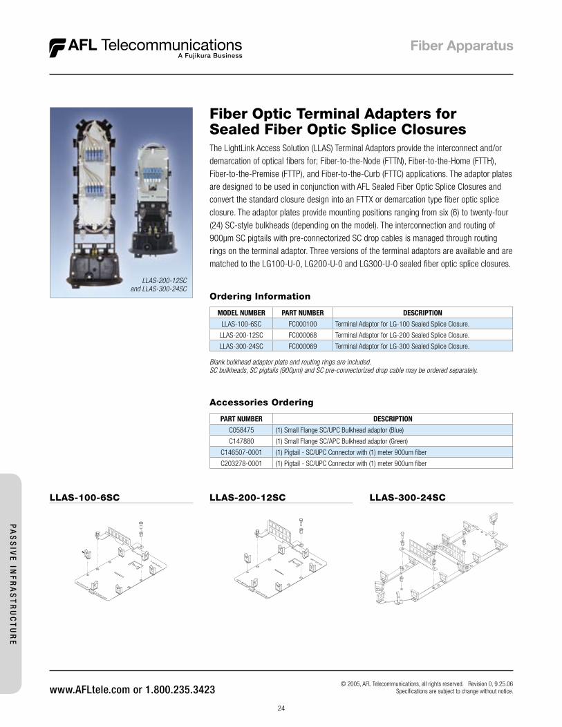
The LightLink Access Solution (LLAS) Terminal Adaptors provide the interconnect and/or demarcation of optical fibers for; Fiber-to-the-Node (FTTN), Fiber-to-the-Home (FTTH), Fiber-to-the-Premise (FTTP), and Fiber-to-the-Curb (FTTC) applications. The adaptor plates are designed to be used in conjunction with AFL Sealed Fiber Optic Splice Closures and convert the standard closure design into an FTTX or demarcation type fiber optic splice closure. The adaptor plates provide mounting positions ranging from six (6) to twenty-four (24) SC-style bulkheads (depending on the model). The interconnection and routing of 900µm SC pigtails with pre-connectorized SC drop cables is managed through routing rings on the terminal adaptor. Three versions of the terminal adaptors are available and are matched to the LG100-U-0, LG200-U-0 and LG300-U-0 sealed fiber optic splice closures.
Fiber Optic Terminal Adapters forSealed Fiber Optic Splice Closures
Ordering Information
MODEL NUMBER PART NUMBER DESCRIPTION
LLAS-100-6SC FC000100 Terminal Adaptor for LG-100 Sealed Splice Closure.
LLAS-200-12SC FC000068 Terminal Adaptor for LG-200 Sealed Splice Closure.
LLAS-300-24SC FC000069 Terminal Adaptor for LG-300 Sealed Splice Closure.
Blank bulkhead adaptor plate and routing rings are included.SC bulkheads, SC pigtails (900µm) and SC pre-connectorized drop cable may be ordered separately.
© 2005, AFL Telecommunications, all rights reserved. Revision 0, 9.25.06 Specifications are subject to change without notice.
LLAS-200-12SCand LLAS-300-24SC
Accessories Ordering
PART NUMBER DESCRIPTION
C058475 (1) Small Flange SC/UPC Bulkhead adaptor (Blue)
C147880 (1) Small Flange SC/APC Bulkhead adaptor (Green)
C146507-0001 (1) Pigtail - SC/UPC Connector with (1) meter 900um fiber
C203278-0001 (1) Pigtail - SC/UPC Connector with (1) meter 900um fiber
PA
SS
IVE
INF
RA
ST
RU
CT
UR
E
LLAS-300-24SCLLAS-200-12SCLLAS-100-6SC
25
© 2002, AFL Telecommunications, all rights reserved. Revision 1, 03.22.06 Specifications are subject to change without notice.
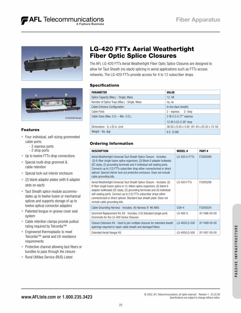
LG-420 FTTx Aerial WeathertightFiber Optic Splice Closures
Ordering Information
DESCRIPTION MODEL # PART #
Aerial Weathertight Universal Taut Sheath Splice Closure - Includes: (2) 6-fiber single fusion splice organizers, (2) Blank 6 adapter bulkeads (SC style), (2) grounding terminals and 4 individual self sealing ports. Connects up to (12) FTTx subscriber drop either connectorized or direct spliced. Special interior lock out protective enclosure. Does not include cable grounding kits.
LG-420-U-FTTx FC000099
Aerial Weathertight Universal Taut Sheath Splice Closure - Includes: (2) 6-fiber single fusion splice or (1) ribbon splice organizers, (2) blank 6 adaptor bulkheads (SC style), (2) grounding terminals and (4) individual self-sealing ports. Connect up to (12) FTTx subscriber drops either connectorized or direct spliced. Standard taut sheath plate. Does not include cable grounding kits.
LG-420-FTTx FC000206
Cable Grounding Harness - Includes; (4) Harness 8” #6 AWG CGH-4 FC000024
Grommet Replacement Kit, Kit - Includes; (10) Standard (single port) Grommets for the LG-400 Series Closures
LG-400-S 911496-00-00
Closure Extension Kit - Used to join multiple closures for extended sheath openings required to repair cable sheath and damaged fibers
LG-400/LG-500 911499-00-00
Extended Aerial Hangar Kit LG-400/LG-500 911497-00-00
The AFL LG-420 FTTx Aerial Weathertight Fiber Optic Splice Closures are designed to allow for Taut Sheath (no slack) splicing in aerial applications such as FTTx access networks. The LG-420 FTTx provide access for 4 to 12 subscriber drops.
Features
• Four individual, self-sizing grommeted cable ports:
- 2 express ports - 2 drop ports• Up to twelve FTTx drop connections
• Special multi-drop grommet & cable retention
• Special lock-out interior enclosure
• (2) blank adaptor plates (with 6 adaptor slots on each)
• Taut Sheath splice module accommo-dates up to twelve fusion or mechanical splices and supports storage of up to twelve optical connector adapters
• Patented tongue-in-groove cover seal system
• Cable retention clamps provide pullout rating required by Telcordia™
• Engineered thermoplastic to meet Telcordia™ aerial and UV resistance requirements
• Protective channel allowing taut fibers or bundles to pass through the closure
• Rural Utilities Service (RUS) Listed
Specifications
PARAMETER VALUE
Splice Capacity (Max.) - Single, Mass 12, 48
Number of Splice Trays (Max.) - Single, Mass na, na
Cable Entrance Configuration In-line (taut sheath)
Cable Ports 2 - express 2- drop
Cable Sizes (Max. O.D. – Min. O.D.) 2 @ 0.3-0.77" express
12 @ 0.22-0.38” drop
Dimensions - (L x D) in. (cm) 36.00 x 8.00 x 4.00 (91.44 x 20.32 x 10.16)
Weight - lbs. (kg) 8.5 (3.86)
(FC000099 Model)
PA
SS
IVE
IN
FR
AS
TR
UC
TU
RE
26
© 2002, AFL Telecommunications, all rights reserved. Revision 1, 03.22.06 Specifi cations are subject to change without notice.
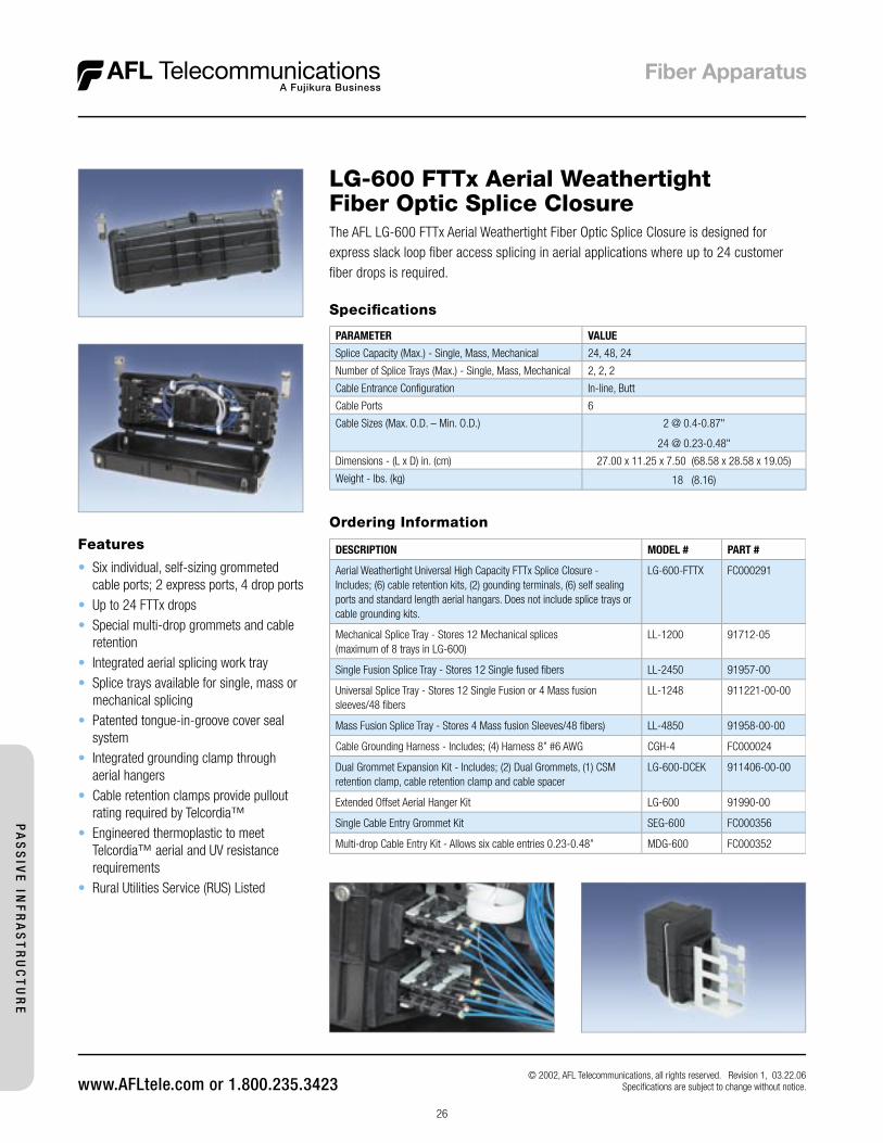
LG-600 FTTx Aerial Weathertight Fiber Optic Splice ClosureThe AFL LG-600 FTTx Aerial Weathertight Fiber Optic Splice Closure is designed for express slack loop fi ber access splicing in aerial applications where up to 24 customer fi ber drops is required.
Ordering Information
DESCRIPTION MODEL # PART #
Aerial Weathertight Universal High Capacity FTTx Splice Closure -Includes; (6) cable retention kits, (2) gounding terminals, (6) self sealing ports and standard length aerial hangars. Does not include splice trays or cable grounding kits.
LG-600-FTTX FC000291
Mechanical Splice Tray - Stores 12 Mechanical splices(maximum of 8 trays in LG-600)
LL-1200 91712-05
Single Fusion Splice Tray - Stores 12 Single fused fi bers LL-2450 91957-00
Universal Splice Tray - Stores 12 Single Fusion or 4 Mass fusion sleeves/48 fi bers
LL-1248 911221-00-00
Mass Fusion Splice Tray - Stores 4 Mass fusion Sleeves/48 fi bers) LL-4850 91958-00-00
Cable Grounding Harness - Includes; (4) Harness 8” #6 AWG CGH-4 FC000024
Dual Grommet Expansion Kit - Includes; (2) Dual Grommets, (1) CSM retention clamp, cable retention clamp and cable spacer
LG-600-DCEK 911406-00-00
Extended Offset Aerial Hanger Kit LG-600 91990-00
Single Cable Entry Grommet Kit SEG-600 FC000356
Multi-drop Cable Entry Kit - Allows six cable entries 0.23-0.48” MDG-600 FC000352
Features
• Six individual, self-sizing grommeted cable ports; 2 express ports, 4 drop ports
• Up to 24 FTTx drops• Special multi-drop grommets and cable
retention• Integrated aerial splicing work tray• Splice trays available for single, mass or
mechanical splicing• Patented tongue-in-groove cover seal
system• Integrated grounding clamp through
aerial hangers• Cable retention clamps provide pullout
rating required by Telcordia™• Engineered thermoplastic to meet
Telcordia™ aerial and UV resistance requirements
• Rural Utilities Service (RUS) Listed
Specifi cations
PARAMETER VALUE
Splice Capacity (Max.) - Single, Mass, Mechanical 24, 48, 24
Number of Splice Trays (Max.) - Single, Mass, Mechanical 2, 2, 2
Cable Entrance Confi guration In-line, Butt
Cable Ports 6
Cable Sizes (Max. O.D. – Min. O.D.) 2 @ 0.4-0.87"
24 @ 0.23-0.48"
Dimensions - (L x D) in. (cm) 27.00 x 11.25 x 7.50 (68.58 x 28.58 x 19.05)
Weight - lbs. (kg) 18 (8.16)
PA
SS
IVE
INF
RA
ST
RU
CT
UR
E
27
Specifications
PARAMETER VALUEMaterial Chassis – aluminumCoatings Electrostatically applied, powder coatColor Antique whiteDimensions (H x W x D) in. (cm) 22.75 x 11.00 x 4.0 (57.79 x 27.94 x 10.16)Weight lbs. (kg) 6.5 (2.95)
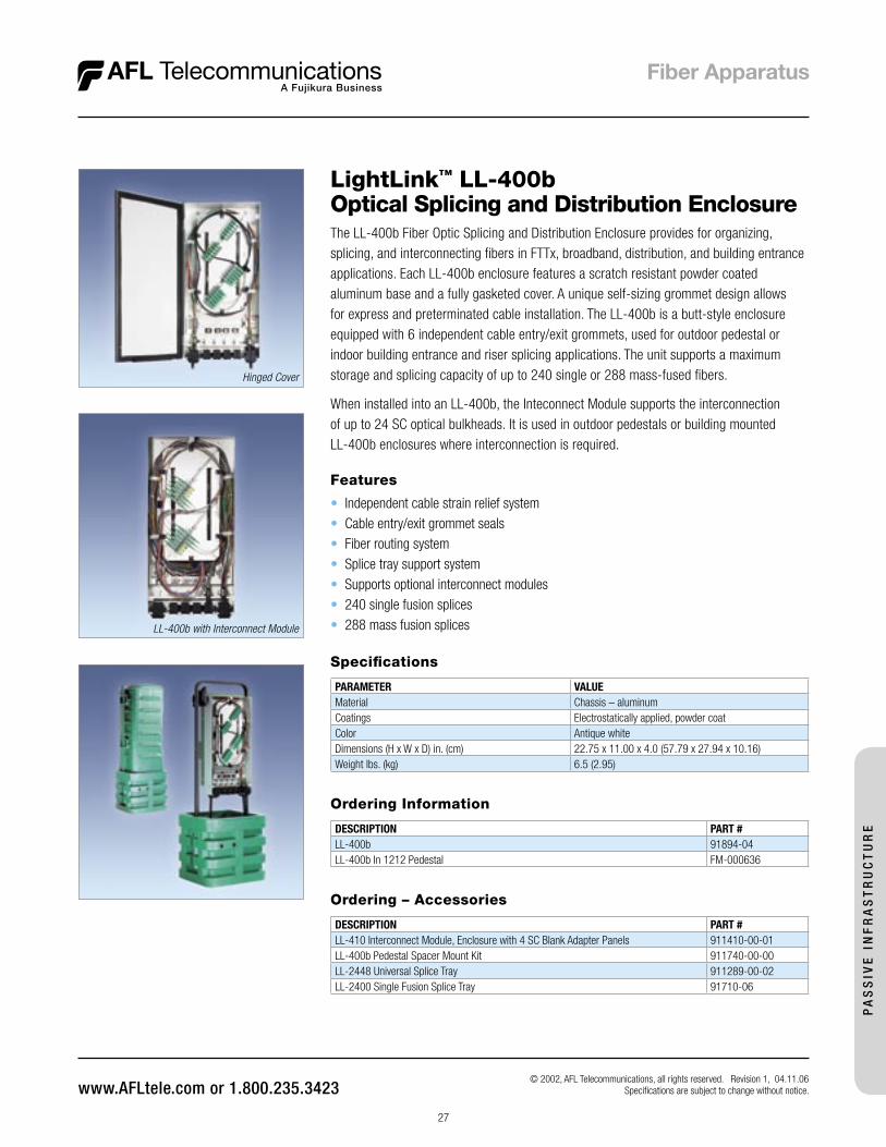
LightLink™ LL-400bOptical Splicing and Distribution Enclosure
Features
• Independent cable strain relief system• Cable entry/exit grommet seals• Fiber routing system• Splice tray support system• Supports optional interconnect modules• 240 single fusion splices• 288 mass fusion splices
Ordering Information
DESCRIPTION PART #LL-400b 91894-04LL-400b In 1212 Pedestal FM-000636
Ordering – Accessories
DESCRIPTION PART #LL-410 Interconnect Module, Enclosure with 4 SC Blank Adapter Panels 911410-00-01LL-400b Pedestal Spacer Mount Kit 911740-00-00LL-2448 Universal Splice Tray 911289-00-02LL-2400 Single Fusion Splice Tray 91710-06
LL-400b with Interconnect Module
© 2002, AFL Telecommunications, all rights reserved. Revision 1, 04.11.06 Specifications are subject to change without notice.
Hinged Cover
The LL-400b Fiber Optic Splicing and Distribution Enclosure provides for organizing, splicing, and interconnecting fibers in FTTx, broadband, distribution, and building entrance applications. Each LL-400b enclosure features a scratch resistant powder coated aluminum base and a fully gasketed cover. A unique self-sizing grommet design allows for express and preterminated cable installation. The LL-400b is a butt-style enclosure equipped with 6 independent cable entry/exit grommets, used for outdoor pedestal or indoor building entrance and riser splicing applications. The unit supports a maximum storage and splicing capacity of up to 240 single or 288 mass-fused fibers.
When installed into an LL-400b, the Inteconnect Module supports the interconnection of up to 24 SC optical bulkheads. It is used in outdoor pedestals or building mounted LL-400b enclosures where interconnection is required.
PA
SS
IVE
IN
FR
AS
TR
UC
TU
RE
28
Specifications
PARAMETER VALUEMaterial Chassis – aluminumCoatings Electrostatically applied, powder coatColor Antique whiteDimensions (H x W x D) in. (cm) 21.63 x 6.63 x 3.25 (54.94 x 16.84 x 8.26)Weight lbs. (kg) 4.74 (1.77)
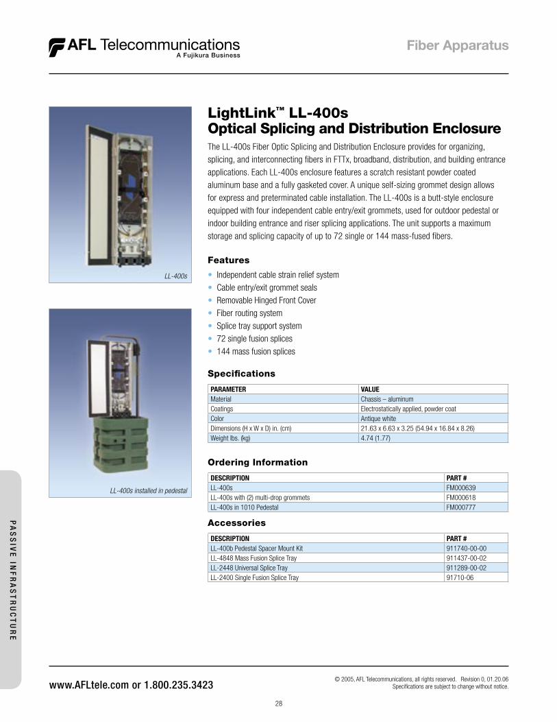
The LL-400s Fiber Optic Splicing and Distribution Enclosure provides for organizing, splicing, and interconnecting fibers in FTTx, broadband, distribution, and building entrance applications. Each LL-400s enclosure features a scratch resistant powder coated aluminum base and a fully gasketed cover. A unique self-sizing grommet design allows for express and preterminated cable installation. The LL-400s is a butt-style enclosure equipped with four independent cable entry/exit grommets, used for outdoor pedestal or indoor building entrance and riser splicing applications. The unit supports a maximum storage and splicing capacity of up to 72 single or 144 mass-fused fibers.
LightLink™ LL-400sOptical Splicing and Distribution Enclosure
Features
• Independent cable strain relief system• Cable entry/exit grommet seals• Removable Hinged Front Cover• Fiber routing system• Splice tray support system• 72 single fusion splices• 144 mass fusion splices
Ordering Information
DESCRIPTION PART #LL-400s FM000639LL-400s with (2) multi-drop grommets FM000618LL-400s in 1010 Pedestal FM000777
Accessories
DESCRIPTION PART #LL-400b Pedestal Spacer Mount Kit 911740-00-00LL-4848 Mass Fusion Splice Tray 911437-00-02LL-2448 Universal Splice Tray 911289-00-02LL-2400 Single Fusion Splice Tray 91710-06
© 2005, AFL Telecommunications, all rights reserved. Revision 0, 01.20.06 Specifications are subject to change without notice.
LL-400s installed in pedestal
LL-400s
PA
SS
IVE
INF
RA
ST
RU
CT
UR
E
29
Specifications
PARAMETER VALUEMaterial SteelCoatings Electrostatically applied, powder coatColor Antique whiteDimensions (H x W x D) in. (cm) 17.5 x 9.0 x 4.0 (44.45 x 22.86 x 10.16)Weight lbs. (kg) 6.5 (2.95)
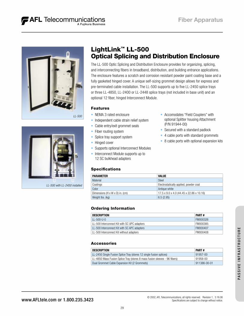
The LL-500 Optic Splicing and Distribution Enclosure provides for organizing, splicing, and interconnecting fibers in broadband, distribution, and building entrance applications. The enclosure features a scratch and corrosion resistant powder paint coating base and a fully gasketed hinged cover. A unique self-sizing grommet design allows for express and pre-terminated cable installation. The LL-500 supports up to five LL-2450 splice trays or three LL-4850, LL-2400 or LL-2448 splice trays (not included in base unit) and an optional 12 fiber, hinged Interconnect Module.
LightLink™ LL-500Optical Splicing and Distribution Enclosure
Features
• NEMA 3 rated enclosure• Independent cable strain relief system• Cable entry/exit grommet seals• Fiber routing system• Splice tray support system• Hinged cover• Supports optional Interconnect Modules• Interconnect Module supports up to
12 SC bulkhead adapters
Ordering Information
DESCRIPTION PART #LL-500-U-0 FM000326LL-500 Interconnect Kit with SC UPC adapters FM000385LL-500 Interconnect Kit with SC APC adapters FM000407LL-500 Interconnect Kit without adapters FM000408
Accessories
DESCRIPTION PART #LL-2450 Single Fusion Splice Tray (stores 12 single fusion splices) 91957-00LL-4850 Mass Fusion Splice Tray (stores 8 mass fusion sleeves - 96 fibers) 91958-00Dual Grommet Cable Expansion Kit (2 Grommets) 911386-00-01
LL-500 with LL-2450 installed
© 2002, AFL Telecommunications, all rights reserved. Revision 1, 3.16.06 Specifications are subject to change without notice.
• Accomodates “Field Couplers” with optional Splitter housing Attachment (P/N 91944-00)
• Secured with a standard padlock• 4 cable ports with standard grommets• 8 cable ports with optional expansion kits
LL-500
PA
SS
IVE
IN
FR
AS
TR
UC
TU
RE

30
LightLink™ OptiNID OPN-1224 Optical Demarcation Closure The OptiNID-1224 is an optical demarcation closure designed for use in either indoor or outdoor environments. It is capable of housing up to 24 bulkhead adapters in two 118 LGX® compatible adapter plates and comes equipped with a splice tray (LL-2425), which holds up to 24 single fusion splices. The OPN-1224 can be either wall or pole-mounted.
Ordering Information
DESCRIPTION MODEL # PART #OptiNID-1224 optioned for up to two 118 LGX® compatible adapter plates. (includes splice tray, does not include adapters plates or adapters)
OPN-1224 DM000183
Blank Filler Panel C215503 C215507SINGLE-MODE (CERAMIC)SCU 6-pack simplex C215602 C215611
SCA 6-pack simplex C215638 C215644
STU 6-pack simplex C215962 C215971
STU 12-pack simplex C223564 C223571
SCU 3-pack duplex (6 fi ber) C215512 C215521
SCU 6-pack duplex (12 fi ber) C219604 C220853
LCU 6-pack duplex (12 fi ber) C215989 C215993MULTI MODE (METAL)SC 6-pack simplex C215626 C215633
ST 6-pack simplex C215968 C215975
ST 12-pack simplex C223567 C223576
SC 3-pack duplex (6 fi ber) C215536 C215543
SC 6-pack duplex (12 fi ber) C220435 C219598
LC 6-pack duplex (12 fi ber) C215998 C216004
MTRJ 6-pack C216079 C216083
Adapter color: SM = Blue MM=Beige
Specifi cations
PARAMETER VALUESDielectric Strength Minimum 2500 Vrms for 1 minute
High Temperature Storage/Mold Stress °F (°C) 14 days at 159 (70.55)
Temperature Cycling with Humidity °F (°C) 150 day cycling from 40-140 (4.44-60) with 95% RH
Impact Test °F (°C) -40 (-40), 5*/lbs. on all external surfaces
Drop Test °F (°C) -40 (-40), 5* (12.7 cm) onto concrete surface 4 times
Rain 24 hours at 10 psi
UV Resistance (Days Exposed) 60 per ASTM-G26-84
Salt Fog (Days Exposed) 60 per ASTM-BLL7-90
Flammability UL94-5V
Chemical Resistance30 Days at 100 °F and 95% RH Subject to:
Resists chipping and/or cracking when subject to: house paint, wasp spray, sulfuric acid, kerosene and sodium hydroxide
Material U.L.® listed fl ame retardant thermoplastic alloy
Dimensions (H x W x D) in. (cm) 12.25 x 12 x 5.25 (22.80 x 22.80 x 7.60)
Cable Entrances in. (cm) diameter - Output 5 x 0.625 (1.5)
Cable Entrances in. (cm) diameter - Input 2 x 0.75 (1.5), 1 x 0.250 (0.6) (ground wire)
Covers Standard - molded-in snap fi nger and “F” termination
Features
• Capacity for up to two 118 LGX® com-patible adapter plates
• Weather-resistant thermoplastic alloy• Self-latching, hinged cover design allows
easy access without loose parts• Self-sealing individual entrance ports
prevent water and insects from entering• Provider override is provided so that
technician can override customer lock • Locations available on front cover for
custom logos
© 2005, AFL Telecommunications, all rights reserved. Revision 0, 1.16.06 Specifi cations are subject to change without notice.
LGX is a registered trademark of Furukawa Electric North America, Inc.
PA
SS
IVE
INF
RA
ST
RU
CT
UR
E
OPN-1224 shown with customer provided cabling, adapter plates and adapters.
31
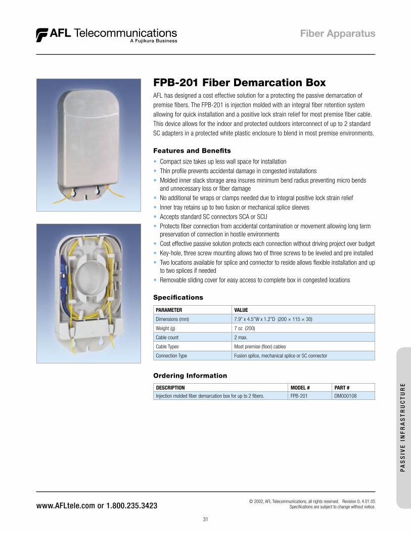
FPB-201 Fiber Demarcation BoxAFL has designed a cost effective solution for a protecting the passive demarcation of premise fibers. The FPB-201 is injection molded with an integral fiber retention system allowing for quick installation and a positive lock strain relief for most premise fiber cable. This device allows for the indoor and protected outdoors interconnect of up to 2 standard SC adapters in a protected white plastic enclosure to blend in most premise environments.
Ordering Information
DESCRIPTION MODEL # PART #
Injection molded fiber demarcation box for up to 2 fibers. FPB-201 DM000108
Features and Benefits
• Compact size takes up less wall space for installation• Thin profile prevents accidental damage in congested installations• Molded inner slack storage area insures minimum bend radius preventing micro bends
and unnecessary loss or fiber damage• No additional tie wraps or clamps needed due to integral positive lock strain relief• Inner tray retains up to two fusion or mechanical splice sleeves• Accepts standard SC connectors SCA or SCU• Protects fiber connection from accidental contamination or movement allowing long term
preservation of connection in hostile environments• Cost effective passive solution protects each connection without driving project over budget• Key-hole, three screw mounting allows two of three screws to be leveled and pre installed• Two locations available for splice and connector to reside allows flexible installation and up
to two splices if needed• Removable sliding cover for easy access to complete box in congested locations
Specifications
PARAMETER VALUE
Dimensions (mm) 7.9” x 4.5”W x 1.2”D (200 × 115 × 30)
Weight (g) 7 oz (200)
Cable count 2 max.
Cable Types Most premise (floor) cables
Connection Type Fusion splice, mechanical splice or SC connector
© 2002, AFL Telecommunications, all rights reserved. Revision 0, 4.01.05 Specifications are subject to change without notice.
PA
SS
IVE
IN
FR
AS
TR
UC
TU
RE
32
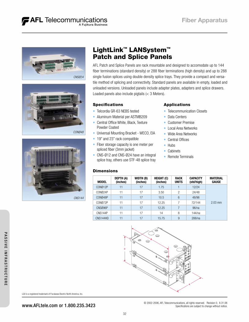
LightLink™ LANSystem™
Patch and Splice Panels
Dimensions
MODELDEPTH (A)(inches)
WIDTH (B)(inches)
HEIGHT (C)(inches)
RACKUNITS
CAPACITY(std/high)
MATERIALGAUGE
CONØ12P 11 17 1.75 1 12/24
2.03 mm
CONØ24P 11 17 3.50 2 24/48
CONØ48P 11 17 10.5 6 48/96
CONØ72P 11 17 12.25 7 72/144
CNSØ96P 11 17 12.25 7 96/na
CNS144P 11 17 14 8 144/na
CNS144HD 11 17 15.75 9 288/na
© 2002-2006, AFL Telecommunications, all rights reserved. Revision 0, 8.31.06 Specifications are subject to change without notice.
LGX is a registered trademark of Furukawa Electric North America, Inc.
CNSØ24
CONØ48
CNS144
AFL Patch and Splice Panels are rack mountable and designed to accomodate up to 144 fiber terminations (standard density) or 288 fiber terminations (high density) and up to 288 single fusion splices using double density splice trays. They provide a compact and versa-tile method of splicing and connectivity. Standard panels are available in empty, loaded and unloaded versions. Unloaded panels include adapter plates, adapters and splice drawers. Loaded panels also include pigtails (< 3 Meters).
Applications
• Telecommunication Closets• Data Centers• Customer Premise• Local Area Networks• Wide Area Networks• Central Offices• Hubs• Cabinets• Remote Terminals
Specifications
• Telcordia GR-63 NEBS tested• Aluminum Material per ASTMB209 • Central Office White, Black, Texture
Powder Coated• Universal Mounting Bracket - WECO, EIA• 19” and 23” rack compatible• Fiber storage capacity is one meter per
spliced fiber (3mm jacket)• CNS-Ø12 and CNS-Ø24 have an integral
splice tray, others use STF-48 splice tray
PA
SS
IVE
INF
RA
ST
RU
CT
UR
E
33
Ordering Information
Select the seven digit part number of the panel you need, specify black or C.O. white, and choose the loading character desired.
C210989 BPart Number Color Loading Charactor
L = Panel with adapters S = Panel with adapters, connectors, & cable stub E = Empty
W = C.O. White B = Black
L
Example: Order number for a CNSØ96 panel Black in color, loaded with, master plate, adapter plates, 96 ASC adapters (12 eight packs), splice drawers, pigtails with connectors, hardware, cable clamp.
LightLink™ LANSystem™ Patch and Splice Panels
Ordering Information - Selection of Standard Configurations (consult customer service for additional configurations)
PART NUMBER CONFIGURATION
1U PATCH AND SPLICE PANELS
C215327 CNSØ12P – EMPTY
C215008 CNSØ12P with 12 USC (PB) adapters (2 Six Packs)118 LGX Internal Splice Tray
FM000214 CNSØ12P with 6 UDL (dup) adapters (2 Three Packs) 118 LGX Internal Splice Tray (Blue)
1U HIGH DENSITY PATCH AND SPLICE PANELS
C215057 CNSØ24HD with 12 UDL (dup) adapters (2 Six Packs)118 LGX Internal Splice Tray
2U PATCH AND SPLICE PANELS
C215158 CNSØ24P – EMPTY
C215086 CNSØ24P with 24 USC (PB) adapters (4 Six Packs) 118 LGX Internal Splice tray
FM000224 CNSØ24P with 12 UDL (dup) adapters (4 three Packs)118 LGX Internal Splice tray
2U HIGH DENSITY PATCH AND SPLICE PANELS
C215134 CNSØ48HD with 24 UDL (dup) adapters (4 Six Packs) 118 LGX Internal Splice tray
6U PATCH AND SPLICE PANELS (1 - 3U PATCH, 1 - 3U SPLICE)
C211534 CNSØ48P – EMPTY
C211543 CNSØ48P with 48 USC (PB) adapters (8 Six Packs) Splice Drawer (2 - 48 position) 118 LGX
FM000234 CNSØ48P with 24 UDL (dup) adapters (8 Three Packs) Splice Drawer (2 - 48 position) 118 LGX
6U HIGH DENSITY PATCH AND SPLICE PANELS
C211594 CNSØ96HD with 48 UDL (dup) adapters (8 Six Packs) Splice Drawer (2 - 48 position) 118 LGX
7U PATCH AND SPLICE PANELS (1 - 4U PATCH, 1 - 3U SPLICE)
C211615 CNSØ72P – EMPTY 118 LGX
C210967 CNSØ72/96P – EMPTY 130 LGX
C211624 CNSØ72P with 72 USC (PB) adapters (12 Six Packs) Splice Drawers (3 - 48 position) 118 LGX
FM000244 CNSØ72P with 36 UDL (dup) adapters (12 Three Packs) Splice Drawers (3 - 48 position) 118 LGX
C210985 CNSØ96P with 96 USC (ZR) adapters (12 Eight Packs) Splice Drawers (2 - 48 position) 130 LGX
7U HIGH DENSITY PATCH AND SPLICE PANELS (1 - 4U PATCH, 1 - 3U SPLICE)
C211673 CNS144HD with 72 UDL (dup) adapters (12 Six Packs) Splice Drawers (3 - 48 position) 130 LGX
8U PATCH AND SPLICE PANELS (1 - 5U PATCH, 1 - 3U SPLICE)
C211696 CNS144P – EMPTY
C211705 CNS144P with 144 USC (PB) adapters (12 Twelve Packs) Splice Drawers (3 - 48 position) 170 LGX
FM000258 CNS144P with 72 UDL (dup) adapters (12 Six Packs) Splice Drawers (3 - 48 position) 170 LGX
9U HIGH DENSITY PATCH AND SPLICE PANELS (1 - 5U PATCH, 1 - 4U SPLICE)
C211756 CNS288HD with 144 UDL (dup) adapters (12 Twelve Packs) Splice Drawers (6 - 48 position) 170 LGX
Connectors/Adapters Available
TYPE DESCRIPTION
ASC Angle Polish SC (ZR) sleeve-SM
ASF Angle Polish SC Duplex (ZR) sleeve-SM
PSC Physical Polish SC (PB) sleeve-MM
PSF Physical Polish SC Duplex (PB) sleeve-MM
USC (PB) Ultra Polish SC wih (PB) sleeve-SM
USC (ZR) Ultra Polish SC with (ZR) sleeve-SM
USF Ultra Polish SC Duplex (ZR) sleeve-SM
PST Physical Polish ST (PB) sleeve-MM
UST Ultra Polish ST (ZR) sleeve-SM
AFC Angle Polish FC (ZR) sleeve-SM
PFC Physical Polish FC (PB) sleeve-MM
UFC Ultra Polish FC (ZR) sleeve-SM
ADL Angle Polish LC Duplex (ZR) sleeve-SM
PDL Physical Polish LC Duplex (PB) sleeve-MM
PLC Physical Polish LC (PB) sleeve-MM
UDL (ZR) Ultra Polish LC Duplex (ZR) sleeve-SM
UDL (PB) Ultra Polish LC Duplex (PB) sleeve-SM
ULC Ultra Polish LC (ZR) sleeve-SM
© 2002-2006, AFL Telecommunications, all rights reserved. Revision 0, 8.31.06 Specifications are subject to change without notice.
Accessories
PART NO. DESCRIPTION
C210850 Cable Clamp (White)
C214522 Cable Clamp (Black)
911442-00-00 STF-48 Telescoping Splice Tray
PA
SS
IVE
IN
FR
AS
TR
UC
TU
RE

34
Features
• Fits comfortably into new and existing interconnect, cross-connect, customer premise, and co-location environments
• Various connector styles & types available• Compatible with industry standard equipment frames• LGX® compatible master plate (170mm)• Modular design• Provides maximum protection of optical components• Available with I/O loose tube stub
AFL Fiber Termination Patch Panels are used where termination and connectivity of up to 144 fi bers (standard density) or 288 (high density) is desired. The panels are designed to accommodate LGX® (170 mm) compatible adapter plates. Standard panels are available in empty, loaded and preterminated versions. Loaded panels include adapters and adapter plates. Preterminated panels include adapters, adapter plates and standard OFNR cable. The fi ber stub for preterminated panels exits the right rear of the unit facing up.
Specifi cations
• Telcordia GR-63 NEBS Tested• Aluminum Material per ASTMB209,
Standard Front Cover Lexan • Central Offi ce White or Black, Textured
Powder Coat Paint• Universal Mounting Bracket WECO, EIA• 19”and 23” Rack Compatable
Applications
• Telecommunication Closets• Data Centers• Customer Premise• Local Area Networks• Wide Area Networks• Central Offi ces• Hubs• Cabinets• Remote Terminals
LightLink™ LANSystem™
Fiber Termination Patch Panels
Dimensions
MODEL DEPTH (A)(inches)
WIDTH (B)(inches)
HEIGHT (C)(inches)
RACKUNITS
CAPACITY(std/high)
UNLOADEDWEIGHT
MATERIALGAUGE
CONØ12P 11 17 1.75 1 12/24 4.0 lbs. 2.03 mm
CONØ24P 11 17 3.50 2 24/48 6.2 lbs. 2.03 mm
CONØ48P 11 17 5.25 3 48/96 8.4 lbs. 2.03 mm
CONØ72P 11 17 7.00 4 72/144 9.0 lbs. 2.03 mm
CONØ96P 11 17 7.00 4 96/na 9.0 lbs. 2.03 mm
CON144P 11 17 8.75 5 144/288 9.0 lbs. 2.03 mm
© 2002-2006, AFL Telecommunications, all rights reserved. Revision 0, 8.29.06 Specifi cations are subject to change without notice.
LGX is a registered trademark of Furukawa Electric North America, Inc.
CONØ12
CONØ48
CON144
PA
SS
IVE
INF
RA
ST
RU
CT
UR
E

35
Ordering Information
Select the seven digit part number of the panel you need, specify black or C.O. white, and choose the loading character desired. When ordering stubbed (S), enter the cable stub length required in meters.
Example: Order number for a 5 RU panel Black in color, loaded with 144 USC adapters (12 twelve packs), connectors and a cable stub 10 meters in length.
LightLink™ LANSystem™ Fiber Termination Patch Panels
Ordering Information - Selection of Standard Configurations (consult customer service for additional configurations)
PART NUMBER CONFIGURATION
1 RU PATCH PANELS
C215327 CNS012P – EMPTY
C211133 CON012P with 12 USC (PB) adapters (2 Six Packs) 118 LGX (Blue)
FM000161 CON012P with 6 UDL (dup) adapters (2 Three Packs) 118 LGX (Blue)
1 RU HIGH DENSITY PATCH PANELS
C211183 CON024HD with 12 UDL (dup) adapters (2 Six Packs) 118 LGX - 24 Fibers
2 RU PATCH PANELS
C215158 CNS024P – EMPTY
C211219 CON024P with 24 USC (PB) adapters (4 Six Packs) 118 LGX (Blue)
FM000171 CON024P with12 UDL (dup) adapters (4 Three Packs) 118 LGX (Blue)
2 RU HIGH DENSITY PATCH PANELS
C211270 CON048HD with 24 UDL (dup) adapters (4 Six Packs) 118 LGX - 48 Fibers
3 RU PATCH PATCH PANELS
C211291 CON048P – EMPTY
C211300 CON048P with 48 USC (PB) adapters (8 Six Packs) 118 LGX (Blue)
FM000181 CON048P with 24 UDL (dup) adapters (8 Three Packs) 118 LGX (Blue)
3 RU HIGH DENSITY PATCH PANELS
C211349 CON096HD with 48 UDL (dup) adapters (8 Six Packs) 118 LGX - 96 Fibers
4 RU PATCH PANELS
C211372 CON072P – EMPTY 118 LGX
FM000344 CON072/96P – EMPTY 130 LGX
C211381 CON072P with 72 USC (PB) adapters (12 Six Packs) 118 LGX (Blue)
FM000191 CON072P with 36 UDL (dup) adapters (12 Three Packs) 118 LGX (Blue)
FM000202 CON096P with 96 USC (PB) adapters (12 Eight Packs) 4U Housing 130 LGX
4 RU HIGH DENSITY PATCH PANELS
C211432 CON144HD with 72 UDL (dup) adapters (12 Six Packs) 130 LGX - 144 Fibers
5 RU PATCH PANELS
C211453 CON144P – EMPTY 170 LGX
C211462 CON144P with 144 USC (PB) adapters (12 Twelve Packs) 170 LGX (Blue)
FM000206 CON144P with 72 UDL (dup) adapters (12 Six Packs) 170 LGX (Blue)
5 RU HIGH DENSITY PATCH PANELS (USES TWO 144 STUBS)
C211511 CON288HD with 144 UDL (dup) adapters (12 Twelve Packs) 170 LGX - 288 Fibers
Accessories
DESCRIPTION PART NUMBER
Cable Clamp (Black) C214522
Cable Clamp (White) C210850
Connectors/Adapters Available
TYPE DESCRIPTION
ASC Angle Polish SC (ZR) sleeve-SM
ASF Angle Polish SC Duplex (ZR) sleeve-SM
PSC Physical Polish SC (PB) sleeve-MM
PSF Physical Polish SC Duplex (PB) sleeve-MM
USC (PB) Ultra Polish SC wih (PB) sleeve-SM
USC (ZR) Ultra Polish SC with (ZR) sleeve-SM
USF Ultra Polish SC Duplex (ZR) sleeve-SM
PST Physical Polish ST (PB) sleeve-MM
UST Ultra Polish ST (ZR) sleeve-SM
AFC Angle Polish FC (ZR) sleeve-SM
PFC Physical Polish FC (PB) sleeve-MM
UFC Ultra Polish FC (ZR) sleeve-SM
ADL Angle Polish LC Duplex (ZR) sleeve-SM
PDL Physical Polish LC Duplex (PB) sleeve-MM
PLC Physical Polish LC (PB) sleeve-MM
UDL (ZR) Ultra Polish LC Duplex (ZR) sleeve-SM
UDL (PB) Ultra Polish LC Duplex (PB) sleeve-SM
ULC Ultra Polish LC (ZR) sleeve-SM
© 2002-2006, AFL Telecommunications, all rights reserved. Revision 0, 8.29.06 Specifications are subject to change without notice.
C211462 BPart Number Color Loading Charactor
L = Panel with adapters S = Panel with adapters, connectors, & cable stub R = Indoor/outdoor loose tube stub E = Empty
W = C.O. White B = Black
S
0002 = 2 meters0004 = 4 metersetc.
0010Cable Stub Length (M)
PA
SS
IVE
IN
FR
AS
TR
UC
TU
RE
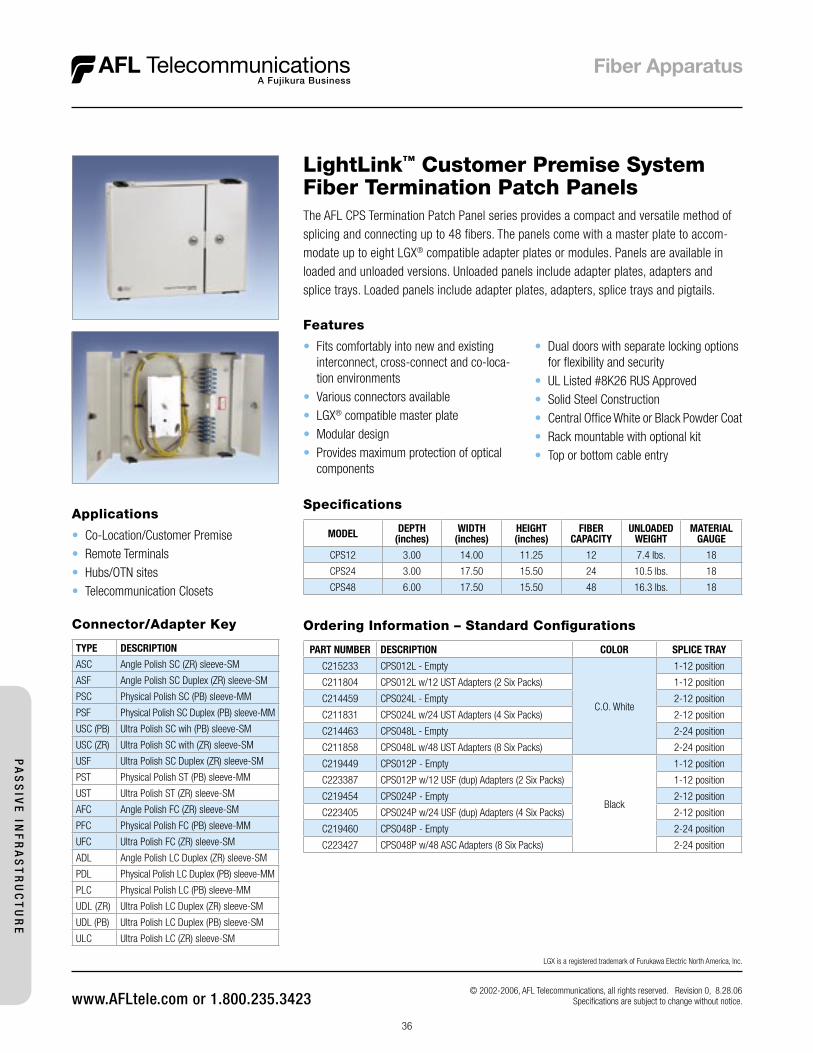
36
Specifications
MODEL DEPTH (inches)
WIDTH (inches)
HEIGHT (inches)
FIBER CAPACITY
UNLOADED WEIGHT
MATERIAL GAUGE
CPS12 3.00 14.00 11.25 12 7.4 lbs. 18
CPS24 3.00 17.50 15.50 24 10.5 lbs. 18
CPS48 6.00 17.50 15.50 48 16.3 lbs. 18
Features
• Fits comfortably into new and existing interconnect, cross-connect and co-loca-tion environments
• Various connectors available• LGX® compatible master plate• Modular design• Provides maximum protection of optical
components
The AFL CPS Termination Patch Panel series provides a compact and versatile method of splicing and connecting up to 48 fibers. The panels come with a master plate to accom-modate up to eight LGX® compatible adapter plates or modules. Panels are available in loaded and unloaded versions. Unloaded panels include adapter plates, adapters and splice trays. Loaded panels include adapter plates, adapters, splice trays and pigtails.
Applications
• Co-Location/Customer Premise• Remote Terminals• Hubs/OTN sites• Telecommunication Closets
LightLink™ Customer Premise SystemFiber Termination Patch Panels
© 2002-2006, AFL Telecommunications, all rights reserved. Revision 0, 8.28.06 Specifications are subject to change without notice.
LGX is a registered trademark of Furukawa Electric North America, Inc.
• Dual doors with separate locking options for flexibility and security
• UL Listed #8K26 RUS Approved• Solid Steel Construction• Central Office White or Black Powder Coat• Rack mountable with optional kit• Top or bottom cable entry
Connector/Adapter Key
TYPE DESCRIPTION
ASC Angle Polish SC (ZR) sleeve-SM
ASF Angle Polish SC Duplex (ZR) sleeve-SM
PSC Physical Polish SC (PB) sleeve-MM
PSF Physical Polish SC Duplex (PB) sleeve-MM
USC (PB) Ultra Polish SC wih (PB) sleeve-SM
USC (ZR) Ultra Polish SC with (ZR) sleeve-SM
USF Ultra Polish SC Duplex (ZR) sleeve-SM
PST Physical Polish ST (PB) sleeve-MM
UST Ultra Polish ST (ZR) sleeve-SM
AFC Angle Polish FC (ZR) sleeve-SM
PFC Physical Polish FC (PB) sleeve-MM
UFC Ultra Polish FC (ZR) sleeve-SM
ADL Angle Polish LC Duplex (ZR) sleeve-SM
PDL Physical Polish LC Duplex (PB) sleeve-MM
PLC Physical Polish LC (PB) sleeve-MM
UDL (ZR) Ultra Polish LC Duplex (ZR) sleeve-SM
UDL (PB) Ultra Polish LC Duplex (PB) sleeve-SM
ULC Ultra Polish LC (ZR) sleeve-SM
Ordering Information – Standard Configurations
PART NUMBER DESCRIPTION COLOR SPLICE TRAY
C215233 CPS012L - Empty
C.O. White
1-12 position
C211804 CPS012L w/12 UST Adapters (2 Six Packs) 1-12 position
C214459 CPS024L - Empty 2-12 position
C211831 CPS024L w/24 UST Adapters (4 Six Packs) 2-12 position
C214463 CPS048L - Empty 2-24 position
C211858 CPS048L w/48 UST Adapters (8 Six Packs) 2-24 position
C219449 CPS012P - Empty
Black
1-12 position
C223387 CPS012P w/12 USF (dup) Adapters (2 Six Packs) 1-12 position
C219454 CPS024P - Empty 2-12 position
C223405 CPS024P w/24 USF (dup) Adapters (4 Six Packs) 2-12 position
C219460 CPS048P - Empty 2-24 position
C223427 CPS048P w/48 ASC Adapters (8 Six Packs) 2-24 position
PA
SS
IVE
INF
RA
ST
RU
CT
UR
E
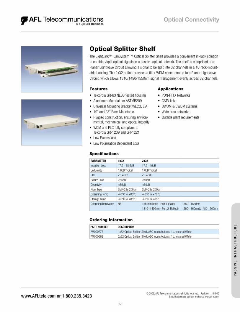
37
Ordering Information
PART NUMBER DESCRIPTION
FM000775 1x32 Optical Splitter Shelf, ASC inputs/outputs, 1U, textured White
FM000662 2x32 Optical Splitter Shelf, ASC inputs/outputs, 1U, textured White
The LightLink™ LanSystem™ Optical Splitter Shelf provides a convenient in-rack solution to combine/split optical signals in a passive optical network. The shelf is comprised of a Planar Lightwave Circuit allowing a signal to be split into 32 channels in a 1U rack-mount-able housing. The 2x32 option provides a filter WDM concatenated to a Planar Lightwave Circuit, which allows 1310/1490/1550nm signal management evenly across 32 channels.
Optical Splitter Shelf
© 2006, AFL Telecommunications, all rights reserved. Revision 1, 8.8.06 Specifications are subject to change without notice.
Features
• Telcordia GR-63 NEBS tested housing• Aluminum Material per ASTMB209• Universal Mounting Bracket WECO, EIA• 19” and 23” Rack Mountable• Rugged construction, ensuring environ-
mental, mechanical, and optical integrity• WDM and PLC fully compliant to
Telcordia GR-1209 and GR-1221• Low Excess loss• Low Polarization Dependent Loss
Applications
• PON-FTTX Networks• CATV links• DWDM & CWDM systems• Wide area networks• Outside plant requirements
Specifications
PARAMETER 1x32 2x32
Insertion Loss 17.5 - 18.5dB 17.5 - 19dB
Uniformity 1.8dB Typical 1.8dB Typical
PDL <0.45dB <0.45dB
Return Loss <55dB <40dB
Directivity <55dB <50dB
Fiber Type SMF-28e 250µm SMF-28e 250µm
Operating Temp -40°C to +85°C -40°C to +70°C
Storage Temp -40°C to +85°C -40°C to +85°C
Operating Bandwidth NA 1550nm Band - Port 1 (Pass) 1550 - 1560nm
1310+1490nm - Port 2 (Reflect) 1260-1360nm & 1480-1500nm
PA
SS
IVE
IN
FR
AS
TR
UC
TU
RE
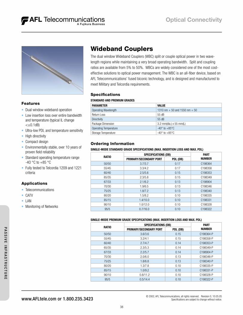
38
Features
• Dual window wideband operation• Low insertion loss over entire bandwidth
and temperature (typical IL change <±0.1dB)
• Ultra-low PDL and temperature sensitivity• High directivity• Compact design• Environmentally stable, over 10 years of
proven field reliability• Standard operating temperature range
-4O °C to +85 °C• Fully tested to Telcordia 1209 and 1221
criteria
Wideband CouplersThe dual window Wideband Couplers (WBC) split or couple optical power in two wave-length regions while maintaining a very broad operating bandwidth. Split and coupling ratios are available from 5% to 50%. WBCs are widely considered one of the most cost-effective solutions to optical power management. The WBC is an all-fiber device, based on AFL Telecommunications’ fused biconic technology, and is designed and manufactured to meet Military and Telcordia requirements.
Applications
• Telecommunications• CATV• LAN• Monitoring of Networks
Ordering InformationSINGLE-MODE STANDARD GRADE SPECIFICATIONS (MAX. INSERTION LOSS AND MAX. PDL)
RATIOSPECIFICATIONS (DB) PART
NUMBERPRIMARY/SECONDARY PORT PDL (DB)50/50 3.7/3.7 0.17 C198364
55/45 3.3/4.2 0.17 C198358
60/40 2.5/5.6 0.15 C198353
65/35 2.3/5.8 0.15 C198349
67/33 2.1/6.2 0.13 C198904
70/30 1.9/6.5 0.13 C198346
75/25 1.8/7.2 0.13 C198340
80/20 1.5/8.2 0.10 C198335
85/15 1.4/10.0 0.10 C198331
90/10 1.0/12.0 0.10 C198328
95/5 0.7/16.0 0.10 C198322
SpecificationsSTANDARD AND PREMIUM GRADES
PARAMETER VALUEOperating Wavelength 1310 nm + 50 and 1550 nm + 50
Return Loss 55 dB
Directivity 55 dB
Package Dimension 3.2 mm(dia.) x 55 mm(L)
Operating Temperature -40° to +85°C
Storage Temperature -40° to +85°C
SINGLE-MODE PREMIUM GRADE SPECIFICATIONS (MAX. INSERTION LOSS AND MAX. PDL)
RATIOSPECIFICATIONS (DB) PART
NUMBERPRIMARY/SECONDARY PORT PDL (DB)50/50 3.6/3.6 0.15 C198364-P
55/45 3.2/4.1 0.15 C198358-P
60/40 2.7/4.7 0.14 C198353-P
65/35 2.3/5.3 0.14 C198349-P
67/33 2.2/5.7 0.14 C198904-P
70/30 2.0/6.0 0.13 C198346-P
75/25 1.8/6.8 0.13 C198340-P
80/20 1.3/7.8 0.10 C198335-P
85/15 1.0/9.2 0.10 C198331-P
90/10 0.8/11.2 0.10 C198328-P
95/5 0.5/14.4 0.10 C198322-P
© 2002, AFL Telecommunications, all rights reserved. Revision 0, 10.05.05 Specifications are subject to change without notice.
PA
SS
IVE
INF
RA
ST
RU
CT
UR
E
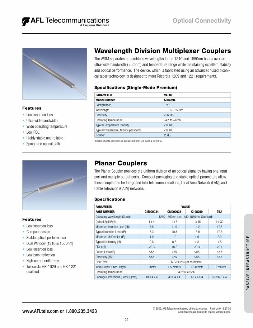
39
Wavelength Division Multiplexer CouplersThe WDM separates or combines wavelengths in the 1310 and 1550nm bands over an ultra-wide bandwidth (+ 20nm) and temperature range while maintaining excellent stability and optical performance. The device, which is fabricated using an advanced fused biconi-cal taper technology, is designed to meet Telcordia 1209 and 1221 requirements.
Features
• Low insertion loss• Ultra-wide bandwidth• Wide operating temperature• Low PDL• Highly stable and reliable• Epoxy-free optical path
Specifications (Single-Mode Premium)
PARAMETER VALUE
Model Number S004794
Configuration 1 x 2
Wavelength 1310 / 1550nm
Directivity <-65dB
Operating Temperature -40º to +85ºC
Typical Temperature Stability <0.1dB
Typical Polarization Stability (passband) <0.1dB
Isolation 20dB
*Isolation of 32dB and higher not available in 63mm L or 69mm L x 3mm OD
© 2002, AFL Telecommunications, all rights reserved. Revision 0, 9.27.06 Specifications are subject to change without notice.
PA
SS
IVE
IN
FR
AS
TR
UC
TU
RE
Planar CouplersThe Planar Coupler provides the uniform division of an optical signal by having one input port and multiple output ports. Compact packaging and stable optical parameters allow these couplers to be integrated into Telecommunications, Local Area Network (LAN), and Cable Television (CATV) networks.
Features
• Low insertion loss• Compact design• Stable optical performance• Dual Window (1310 & 1550nm)• Low insertion loss• Low back reflection• High output uniformity• Telecordia GR-1029 and GR-1221
qualified
Specifications
PARAMETER VALUE
PART NUMBER CM000034 CM000033 C198299 TBA
Operating Wavelength (Grade) 1260-1360nm and 1480-1580nm (Standard)
Optical Split Ratio 1 x 4 1 x 8 1 x 16 1 x 32
Maximum Insertion Loss (dB) 7.5 11.0 14.2 17.8
Typical Insertion Loss (dB) 7.3 10.8 13.9 17.5
Maximum Uniformity (dB) 1.0 1.0 1.5 2.0
Typical Uniformity (dB) 0.8 0.8 1.3 1.8
PDL (dB) <0.3 <0.3 <0.4 <0.4
Return Loss (dB) >55 >55 >55 >55
Directivity (dB) >55 >55 >55 >55
Fiber Type SMF28e 250µm equivalent
Input/Output Fiber Length 1 meter 1.5 meters 1.5 meters 1.5 meters
Operating Temperature –40° to +85°C
Package Dimensions (LxWxH) (mm) 40 x 4 x 4 40 x 4 x 4 40 x 4 x 4 50 x 6.5 x 4
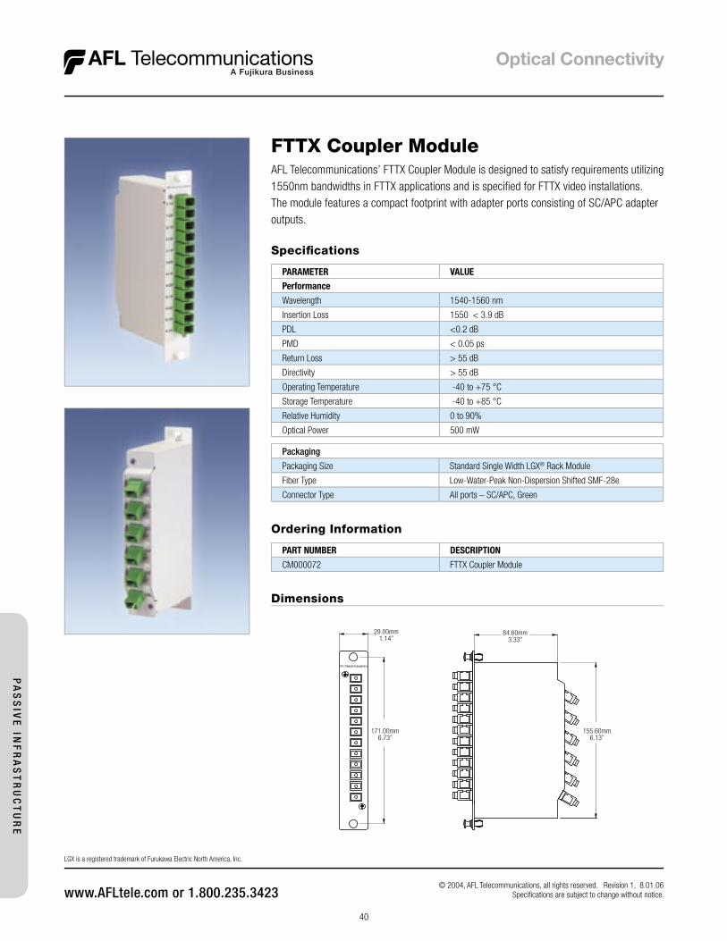
40
FTTX Coupler ModuleAFL Telecommunications’ FTTX Coupler Module is designed to satisfy requirements utilizing1550nm bandwidths in FTTX applications and is specifi ed for FTTX video installations. The module features a compact footprint with adapter ports consisting of SC/APC adapter outputs.
Specifi cations
PARAMETER VALUE
Performance
Wavelength 1540-1560 nm
Insertion Loss 1550 < 3.9 dB
PDL <0.2 dB
PMD < 0.05 ps
Return Loss > 55 dB
Directivity > 55 dB
Operating Temperature -40 to +75 °C
Storage Temperature -40 to +85 °C
Relative Humidity 0 to 90%
Optical Power 500 mW
Packaging
Packaging Size Standard Single Width LGX® Rack Module
Fiber Type Low-Water-Peak Non-Dispersion Shifted SMF-28e
Connector Type All ports – SC/APC, Green
Dimensions
Ordering Information
PART NUMBER DESCRIPTION
CM000072 FTTX Coupler Module
84.60mm3.33”
155.60mm6.13”
29.00mm1.14”
171.00mm6.73”
© 2004, AFL Telecommunications, all rights reserved. Revision 1, 8.01.06 Specifi cations are subject to change without notice.
LGX is a registered trademark of Furukawa Electric North America, Inc.
PA
SS
IVE
INF
RA
ST
RU
CT
UR
E

41
Specifications
PARAMETER VALUE
1550 Band – Port 1 (Pass) 1550-1560 nm
1310 + 1490 Band – Port 2 (Reflect) 1260-1360 & 1480-1500 nm
Insertion Loss 1550 < 1.2 dB1310 + 1490 < 1.2 dB
Isolation 1550 > 25 dB1310 + 1490 > 20 dB
PDL <0.2 dB
PMD < 0.2 ps
Return Loss > 50 dB
Directivity > 50 dB
Operating Temperature -40 to +75 °C
Storage Temperature -40 to +85 °C
Relative Humidity 0 to 90%
Optical Power 500 mW
PACKAGING
Packaging Size Standard Single Width LGX® Rack Module
Fiber Type Low-Water-Peak Non-Dispersion Shifted SMF-28e
Connector Type Port 3 (Common) – SC/APCPort 1 (Data) – SC/UPCPort 2 (Video) – SC/APC
Ordering Information
PART NUMBER DESCRIPTION
CM000043 FTTX WDM Module
84.60mm3.33”
155.60mm6.13”
29.00mm1.14”
171.00mm6.73”
© 2004, AFL Telecommunications, all rights reserved. Revision 1, 8.1.06Specifications are subject to change without notice.
FTTX WDM ModuleThe AFL Telecommunications’ FTTX WDM Module is designed to satisfy requirements utilizing 1310, 1490 and 1550nm bandwidths in FTTX applications. The module features a compact footprint with adapter ports consisting of SC (UPC or APC) outputs.
Dimensions
LGX is a registered trademark of Furukawa Electric North America, Inc.
PA
SS
IVE
IN
FR
AS
TR
UC
TU
RE
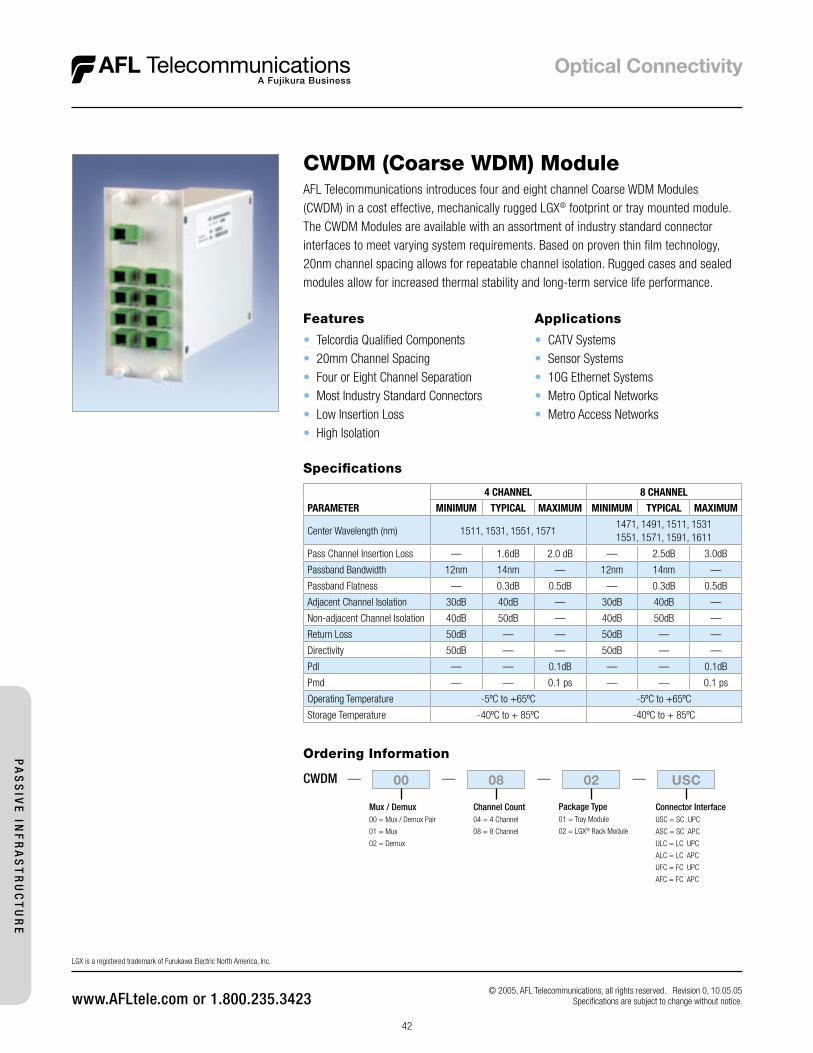
42
CWDM (Coarse WDM) ModuleAFL Telecommunications introduces four and eight channel Coarse WDM Modules (CWDM) in a cost effective, mechanically rugged LGX® footprint or tray mounted module. The CWDM Modules are available with an assortment of industry standard connector interfaces to meet varying system requirements. Based on proven thin film technology, 20nm channel spacing allows for repeatable channel isolation. Rugged cases and sealed modules allow for increased thermal stability and long-term service life performance.
Applications
• CATV Systems• Sensor Systems• 10G Ethernet Systems• Metro Optical Networks• Metro Access Networks
Features
• Telcordia Qualified Components • 20mm Channel Spacing • Four or Eight Channel Separation • Most Industry Standard Connectors• Low Insertion Loss• High Isolation
Specifications
PARAMETER
4 CHANNEL 8 CHANNEL
MINIMUM TYPICAL MAXIMUM MINIMUM TYPICAL MAXIMUM
Center Wavelength (nm) 1511, 1531, 1551, 15711471, 1491, 1511, 15311551, 1571, 1591, 1611
Pass Channel Insertion Loss — 1.6dB 2.0 dB — 2.5dB 3.0dB
Passband Bandwidth 12nm 14nm — 12nm 14nm —
Passband Flatness — 0.3dB 0.5dB — 0.3dB 0.5dB
Adjacent Channel Isolation 30dB 40dB — 30dB 40dB —
Non-adjacent Channel Isolation 40dB 50dB — 40dB 50dB —
Return Loss 50dB — — 50dB — —
Directivity 50dB — — 50dB — —
Pdl — — 0.1dB — — 0.1dB
Pmd — — 0.1 ps — — 0.1 ps
Operating Temperature -5ºC to +65ºC -5ºC to +65ºC
Storage Temperature -40ºC to + 85ºC -40ºC to + 85ºC
Channel Count04 = 4 Channel
08 = 8 Channel
Connector InterfaceUSC = SC UPC
ASC = SC APC
ULC = LC UPC
ALC = LC APC
UFC = FC UPC
AFC = FC APC
Package Type01 = Tray Module
02 = LGX® Rack Module
Ordering Information
Mux / Demux00 = Mux / Demux Pair
01 = Mux
02 = Demux
00 08 02 USC———CWDM —
© 2005, AFL Telecommunications, all rights reserved. Revision 0, 10.05.05 Specifications are subject to change without notice.
LGX is a registered trademark of Furukawa Electric North America, Inc.
PA
SS
IVE
INF
RA
ST
RU
CT
UR
E
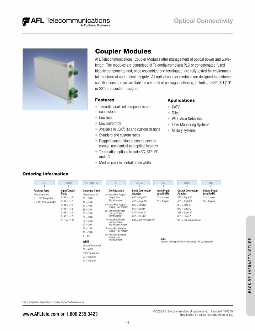
43
Features
• Telcordia qualified components and connectors
• Low loss• Low uniformity• Available in LGX®, RU and custom designs• Standard and custom ratios• Rugged construction to ensure environ-
mental, mechanical and optical integrity• Termination options include SC, ST®, FC
and LC• Module color is central office white
Coupler ModulesAFL Telecommunications’ Coupler Modules offer management of optical power and wave-length. The modules are comprised of Telcordia-compliant PLC or concatenated fused biconic components and, once assembled and terminated, are fully tested for environmen-tal, mechanical and optical integrity. All optical coupler modules are designed to customer specifications and are available in a variety of package platforms, including LGX®, RU (19” or 23”) and custom designs.
Applications
• CATV• Telco• Wide Area Networks• Fiber Monitoring Systems• Military systems
Ordering Information
Note: Dynamic field expands to accommodate 1XN configurations
Output Connector/AdapterASC = Angle SC
AFC = Angle FC
USC = Ultra SC
UFC = Ultra FC
SST = Super ST
ULC = Ultra LC
000 = Non-connectorized
Output PigtailLength (M)01 = 1 meter
00 = Adapter
Input Connector/AdapterASC = Angle SC
AFC = Angle FC
USC = Ultra SC
UFC = Ultra FC
SST = Super ST
ULC = Ultra LC
000 = Non-connectorized
Configuration A = Input Rear Adapter Output Front Pigtail/Jumper
C = Input Rear Adapter Output Front Adapter
D = Input Front Pigtail/ Jumper Output Front Adapter
E = Input Front Pigtail/ Jumper Output Front Pigtail/Jumper
F = Input Front Adapter Output Front Adapter
G = Input Front Adapter Output Front Pigtail/Jumper
Input PigtailLength (M)01 = 1 meter
00 = Adapter
Input/OutputPorts 0102 = 1 x 2
0103 = 1 x 3
0104 = 1 x 4
0105 = 1 x 5
0106 = 1 x 6
0108 = 1 x 8
0110 = 1 x 10
Coupling Ratio(First Character)
50 = 50%
45 = 45%
40 = 40%
35 = 35%
33 = 33%
30 = 30%
25 = 25%
20 = 20%
15 = 15%
10 = 10%
5 = 5%
WDM(Second Character)
00 = WDM
(Third Character)
20 = Isolation
40 = Isolation
C 0102 50 00 20 F ASC 00 ASC 00
Package Type(First Character)
C = LGX® Compatible
D = 19” Rack Mountable
© 2002, AFL Telecommunications, all rights reserved. Revision 0, 10.05.05 Specifications are subject to change without notice.
LGX is a registered trademark of Furukawa Electric North America, Inc.
PA
SS
IVE
IN
FR
AS
TR
UC
TU
RE
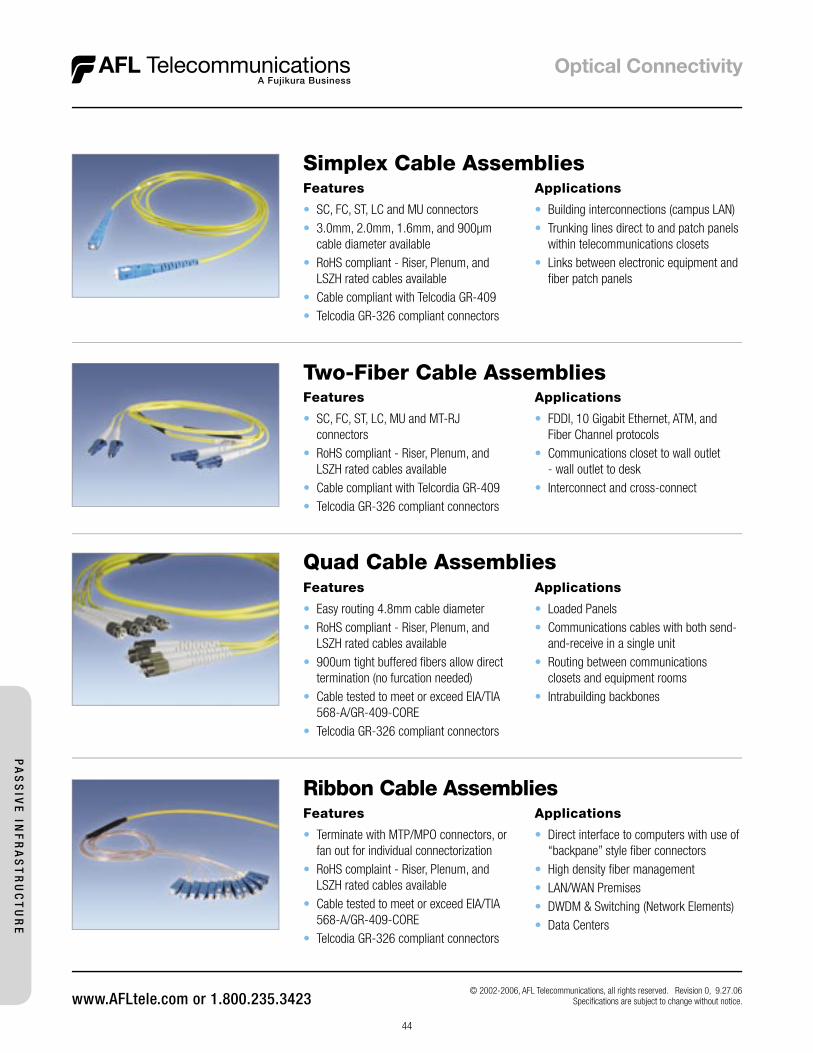
44
Features
• SC, FC, ST, LC and MU connectors• 3.0mm, 2.0mm, 1.6mm, and 900µm
cable diameter available• RoHS compliant - Riser, Plenum, and
LSZH rated cables available• Cable compliant with Telcodia GR-409• Telcodia GR-326 compliant connectors
Simplex Cable Assemblies
© 2002-2006, AFL Telecommunications, all rights reserved. Revision 0, 9.27.06 Specifi cations are subject to change without notice.
Applications
• Building interconnections (campus LAN)• Trunking lines direct to and patch panels
within telecommunications closets• Links between electronic equipment and
fi ber patch panels
Two-Fiber Cable AssembliesFeatures
• SC, FC, ST, LC, MU and MT-RJ connectors
• RoHS compliant - Riser, Plenum, and LSZH rated cables available
• Cable compliant with Telcordia GR-409 • Telcodia GR-326 compliant connectors
Applications
• FDDI, 10 Gigabit Ethernet, ATM, and Fiber Channel protocols
• Communications closet to wall outlet - wall outlet to desk
• Interconnect and cross-connect
Features
• Easy routing 4.8mm cable diameter • RoHS compliant - Riser, Plenum, and
LSZH rated cables available • 900um tight buffered fi bers allow direct
termination (no furcation needed) • Cable tested to meet or exceed EIA/TIA
568-A/GR-409-CORE • Telcodia GR-326 compliant connectors
Applications
• Loaded Panels • Communications cables with both send-
and-receive in a single unit • Routing between communications
closets and equipment rooms • Intrabuilding backbones
Quad Cable Assemblies
Ribbon Cable AssembliesFeatures
• Terminate with MTP/MPO connectors, or fan out for individual connectorization
• RoHS complaint - Riser, Plenum, and LSZH rated cables available
• Cable tested to meet or exceed EIA/TIA 568-A/GR-409-CORE
• Telcodia GR-326 compliant connectors
Applications
• Direct interface to computers with use of “backpane” style fi ber connectors
• High density fi ber management • LAN/WAN Premises • DWDM & Switching (Network Elements) • Data Centers
PA
SS
IVE
INF
RA
ST
RU
CT
UR
E
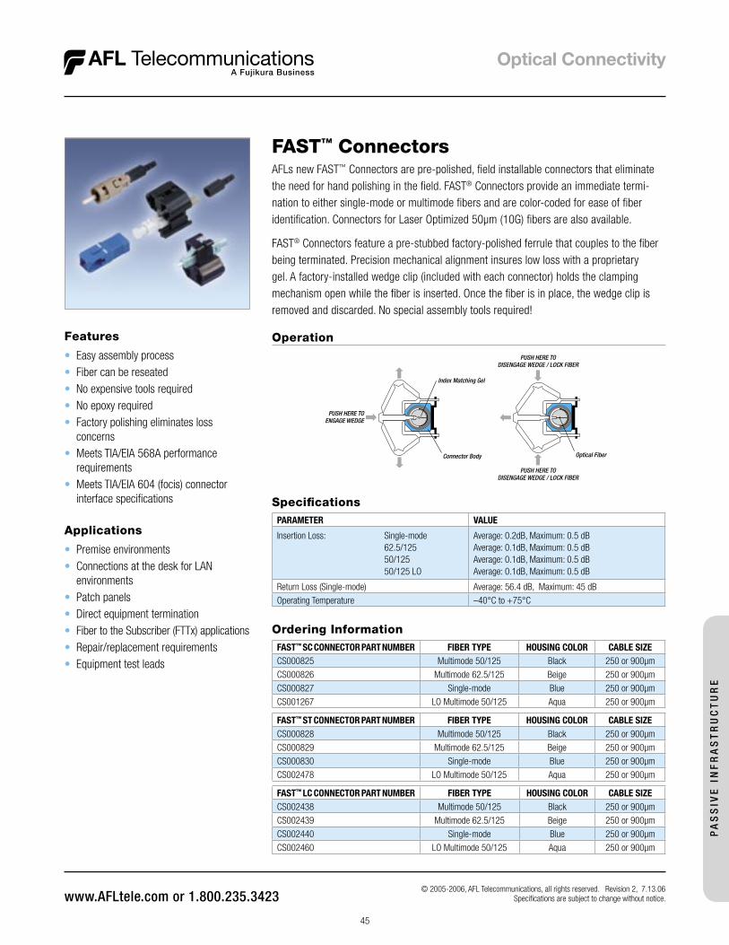
45
© 2005-2006, AFL Telecommunications, all rights reserved. Revision 2, 7.13.06 Specifications are subject to change without notice.
FAST™ ConnectorsAFLs new FAST™ Connectors are pre-polished, field installable connectors that eliminate the need for hand polishing in the field. FAST® Connectors provide an immediate termi-nation to either single-mode or multimode fibers and are color-coded for ease of fiber identification. Connectors for Laser Optimized 50µm (10G) fibers are also available.
FAST® Connectors feature a pre-stubbed factory-polished ferrule that couples to the fiber being terminated. Precision mechanical alignment insures low loss with a proprietary gel. A factory-installed wedge clip (included with each connector) holds the clamping mechanism open while the fiber is inserted. Once the fiber is in place, the wedge clip is removed and discarded. No special assembly tools required!
Features
• Easy assembly process• Fiber can be reseated• No expensive tools required• No epoxy required • Factory polishing eliminates loss
concerns• Meets TIA/EIA 568A performance
requirements• Meets TIA/EIA 604 (focis) connector
interface specifications
Ordering InformationFAST™ SC CONNECTOR PART NUMBER FIBER TYPE HOUSING COLOR CABLE SIZECS000825 Multimode 50/125 Black 250 or 900µm
CS000826 Multimode 62.5/125 Beige 250 or 900µm
CS000827 Single-mode Blue 250 or 900µm
CS001267 LO Multimode 50/125 Aqua 250 or 900µm
Applications
• Premise environments• Connections at the desk for LAN
environments• Patch panels• Direct equipment termination• Fiber to the Subscriber (FTTx) applications• Repair/replacement requirements• Equipment test leads
SpecificationsPARAMETER VALUE
Insertion Loss: Single-mode 62.5/125 50/125 50/125 LO
Average: 0.2dB, Maximum: 0.5 dBAverage: 0.1dB, Maximum: 0.5 dBAverage: 0.1dB, Maximum: 0.5 dBAverage: 0.1dB, Maximum: 0.5 dB
Return Loss (Single-mode) Average: 56.4 dB, Maximum: 45 dB
Operating Temperature –40°C to +75°C
Operation
PUSH HERE TOENGAGE WEDGE
PUSH HERE TODISENGAGE WEDGE / LOCK FIBER
PUSH HERE TODISENGAGE WEDGE / LOCK FIBER
Connector Body Optical Fiber
Index Matching Gel
FAST™ LC CONNECTOR PART NUMBER FIBER TYPE HOUSING COLOR CABLE SIZECS002438 Multimode 50/125 Black 250 or 900µm
CS002439 Multimode 62.5/125 Beige 250 or 900µm
CS002440 Single-mode Blue 250 or 900µm
CS002460 LO Multimode 50/125 Aqua 250 or 900µm
FAST™ ST CONNECTOR PART NUMBER FIBER TYPE HOUSING COLOR CABLE SIZECS000828 Multimode 50/125 Black 250 or 900µm
CS000829 Multimode 62.5/125 Beige 250 or 900µm
CS000830 Single-mode Blue 250 or 900µm
CS002478 LO Multimode 50/125 Aqua 250 or 900µm
PA
SS
IVE
IN
FR
AS
TR
UC
TU
RE
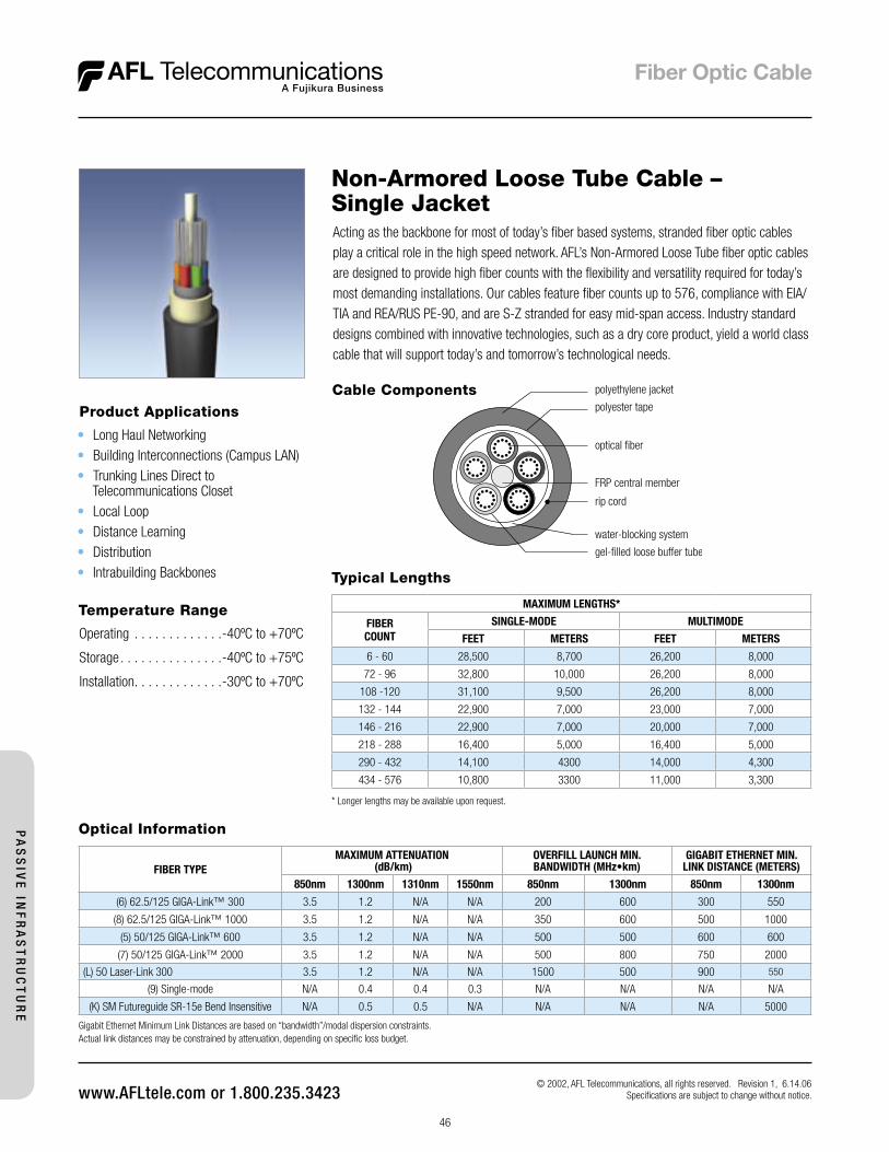
46
© 2002, AFL Telecommunications, all rights reserved. Revision 1, 6.14.06 Specifications are subject to change without notice.
Non-Armored Loose Tube Cable – Single Jacket
Temperature Range
Operating . . . . . . . . . . . . .-40ºC to +70ºC
Storage . . . . . . . . . . . . . . .-40ºC to +75ºC
Installation . . . . . . . . . . . . .-30ºC to +70ºC
Acting as the backbone for most of today’s fiber based systems, stranded fiber optic cables play a critical role in the high speed network. AFL’s Non-Armored Loose Tube fiber optic cables are designed to provide high fiber counts with the flexibility and versatility required for today’s most demanding installations. Our cables feature fiber counts up to 576, compliance with EIA/TIA and REA/RUS PE-90, and are S-Z stranded for easy mid-span access. Industry standard designs combined with innovative technologies, such as a dry core product, yield a world class cable that will support today’s and tomorrow’s technological needs.
Product Applications
• Long Haul Networking• Building Interconnections (Campus LAN)• Trunking Lines Direct to
Telecommunications Closet• Local Loop• Distance Learning• Distribution• Intrabuilding Backbones
Cable Components
Typical Lengths
MAXIMUM LENGTHS*
FIBERCOUNT
SINGLE-MODE MULTIMODE
FEET METERS FEET METERS
6 - 60 28,500 8,700 26,200 8,000
72 - 96 32,800 10,000 26,200 8,000
108 -120 31,100 9,500 26,200 8,000
132 - 144 22,900 7,000 23,000 7,000
146 - 216 22,900 7,000 20,000 7,000
218 - 288 16,400 5,000 16,400 5,000
290 - 432 14,100 4300 14,000 4,300
434 - 576 10,800 3300 11,000 3,300
* Longer lengths may be available upon request.
Optical Information
FIBER TYPEMAXIMUM ATTENUATION
(dB/km)OVERFILL LAUNCH MIN.BANDWIDTH (MHz•km)
GIGABIT ETHERNET MIN.LINK DISTANCE (METERS)
850nm 1300nm 1310nm 1550nm 850nm 1300nm 850nm 1300nm
(6) 62.5/125 GIGA-Link™ 300 3.5 1.2 N/A N/A 200 600 300 550
(8) 62.5/125 GIGA-Link™ 1000 3.5 1.2 N/A N/A 350 600 500 1000
(5) 50/125 GIGA-Link™ 600 3.5 1.2 N/A N/A 500 500 600 600
(7) 50/125 GIGA-Link™ 2000 3.5 1.2 N/A N/A 500 800 750 2000
(L) 50 Laser-Link 300 3.5 1.2 N/A N/A 1500 500 900 550
(9) Single-mode N/A 0.4 0.4 0.3 N/A N/A N/A N/A
(K) SM Futureguide SR-15e Bend Insensitive N/A 0.5 0.5 N/A N/A N/A N/A 5000
Gigabit Ethernet Minimum Link Distances are based on “bandwidth”/modal dispersion constraints. Actual link distances may be constrained by attenuation, depending on specific loss budget.
PA
SS
IVE
INF
RA
ST
RU
CT
UR
E
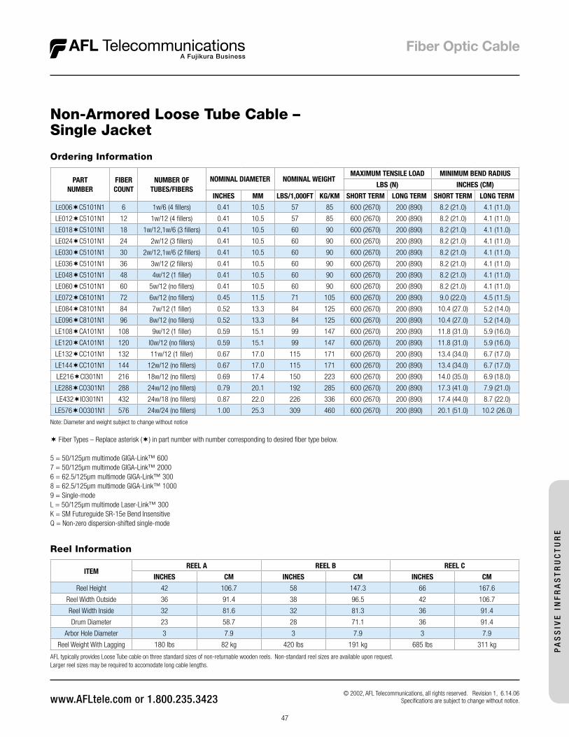
47
© 2002, AFL Telecommunications, all rights reserved. Revision 1, 6.14.06 Specifications are subject to change without notice.
Non-Armored Loose Tube Cable – Single Jacket
Ordering Information
PARTNUMBER
FIBERCOUNT
NUMBER OFTUBES/FIBERS
NOMINAL DIAMETER NOMINAL WEIGHTMAXIMUM TENSILE LOAD MINIMUM BEND RADIUS
LBS (N) INCHES (CM)
INCHES MM LBS/1,000FT KG/KM SHORT TERM LONG TERM SHORT TERM LONG TERM
LE006C5101N1 6 1w/6 (4 fillers) 0.41 10.5 57 85 600 (2670) 200 (890) 8.2 (21.0) 4.1 (11.0)
LE012C5101N1 12 1w/12 (4 fillers) 0.41 10.5 57 85 600 (2670) 200 (890) 8.2 (21.0) 4.1 (11.0)
LE018C5101N1 18 1w/12,1w/6 (3 fillers) 0.41 10.5 60 90 600 (2670) 200 (890) 8.2 (21.0) 4.1 (11.0)
LE024C5101N1 24 2w/12 (3 fillers) 0.41 10.5 60 90 600 (2670) 200 (890) 8.2 (21.0) 4.1 (11.0)
LE030C5101N1 30 2w/12,1w/6 (2 fillers) 0.41 10.5 60 90 600 (2670) 200 (890) 8.2 (21.0) 4.1 (11.0)
LE036C5101N1 36 3w/12 (2 fillers) 0.41 10.5 60 90 600 (2670) 200 (890) 8.2 (21.0) 4.1 (11.0)
LE048C5101N1 48 4w/12 (1 filler) 0.41 10.5 60 90 600 (2670) 200 (890) 8.2 (21.0) 4.1 (11.0)
LE060C5101N1 60 5w/12 (no fillers) 0.41 10.5 60 90 600 (2670) 200 (890) 8.2 (21.0) 4.1 (11.0)
LE072C6101N1 72 6w/12 (no fillers) 0.45 11.5 71 105 600 (2670) 200 (890) 9.0 (22.0) 4.5 (11.5)
LE084C8101N1 84 7w/12 (1 filler) 0.52 13.3 84 125 600 (2670) 200 (890) 10.4 (27.0) 5.2 (14.0)
LE096C8101N1 96 8w/12 (no fillers) 0.52 13.3 84 125 600 (2670) 200 (890) 10.4 (27.0) 5.2 (14.0)
LE108CA101N1 108 9w/12 (1 filler) 0.59 15.1 99 147 600 (2670) 200 (890) 11.8 (31.0) 5.9 (16.0)
LE120CA101N1 120 l0w/12 (no fillers) 0.59 15.1 99 147 600 (2670) 200 (890) 11.8 (31.0) 5.9 (16.0)
LE132CC101N1 132 11w/12 (1 filler) 0.67 17.0 115 171 600 (2670) 200 (890) 13.4 (34.0) 6.7 (17.0)
LE144CC101N1 144 12w/12 (no fillers) 0.67 17.0 115 171 600 (2670) 200 (890) 13.4 (34.0) 6.7 (17.0)
LE216CI301N1 216 18w/12 (no fillers) 0.69 17.4 150 223 600 (2670) 200 (890) 14.0 (35.0) 6.9 (18.0)
LE288CO301N1 288 24w/12 (no fillers) 0.79 20.1 192 285 600 (2670) 200 (890) 17.3 (41.0) 7.9 (21.0)
LE432IO301N1 432 24w/18 (no fillers) 0.87 22.0 226 336 600 (2670) 200 (890) 17.4 (44.0) 8.7 (22.0)
LE576OO301N1 576 24w/24 (no fillers) 1.00 25.3 309 460 600 (2670) 200 (890) 20.1 (51.0) 10.2 (26.0) Note: Diameter and weight subject to change without notice
Fiber Types – Replace asterisk () in part number with number corresponding to desired fiber type below.
5 = 50/125µm multimode GIGA-Link™ 6007 = 50/125µm multimode GIGA-Link™ 20006 = 62.5/125µm multimode GIGA-Link™ 3008 = 62.5/125µm multimode GIGA-Link™ 10009 = Single-modeL = 50/125µm multimode Laser-Link™ 300K = SM Futureguide SR-15e Bend InsensitiveQ = Non-zero dispersion-shifted single-mode
Reel Information
ITEM REEL A REEL B REEL C
INCHES CM INCHES CM INCHES CM
Reel Height 42 106.7 58 147.3 66 167.6
Reel Width Outside 36 91.4 38 96.5 42 106.7
Reel Width Inside 32 81.6 32 81.3 36 91.4
Drum Diameter 23 58.7 28 71.1 36 91.4
Arbor Hole Diameter 3 7.9 3 7.9 3 7.9
Reel Weight With Lagging 180 lbs 82 kg 420 lbs 191 kg 685 lbs 311 kg
AFL typically provides Loose Tube cable on three standard sizes of non-returnable wooden reels. Non-standard reel sizes are available upon request. Larger reel sizes may be required to accomodate long cable lengths.
PA
SS
IVE
IN
FR
AS
TR
UC
TU
RE

48
© 2002-2006, AFL Telecommunications, all rights reserved. Revision 0, 9.28.06 Specifications are subject to change without notice.
Uniflex® Indoor/Outdoor Loose Tube Cable
Applications• Service (Drop) Cables• Building Interconnections (Campus LAN)• Connectorized Trunking Cables• Distance Learning• Distribution
Single tube products allow for installations that require a high degree of flexibility combined with a small cable diameter. AFL Telecommunications’s Uniflex® is the ultimate solution for flexible, connectorized applications, as well as crowded ducts in existing fiber applications, and can be lashed to an aerial messenger.
Cable Components������������
�����������������
�����������
�������������
������������������
�������
PA
SS
IVE
INF
RA
ST
RU
CT
UR
E
Indoor/Outdoor Loose Tube CableIndoor/outdoor stranded loose tube combines the robust mechanical and environmental characteristics of an outside plant cable with the flexibility of an inside plant riser cable. Costly splice locations entering a building are avoided, routing directly from the outside plant to telecommunications closets, or distribution frames through the riser of a building.
Applications
• Building Interconnections (Campus LAN)• Trunking Lines Direct to Closet• Local Loop• Distance Learning• Distribution• Intrabuilding Backbones
����������
�����������������
������
���������������������
������������������
�������������
��������
����������������������������
Cable Components
Uniflex® Non-Armored Loose Tube Cable
Product Applications
• Service (Drop) Cables• Building Interconnections (Campus LAN)• Connectorized Trunking Cables• Distance Learning• Distribution
������������
�����������������
�����������
�������������
������������������
�������
Cable Components
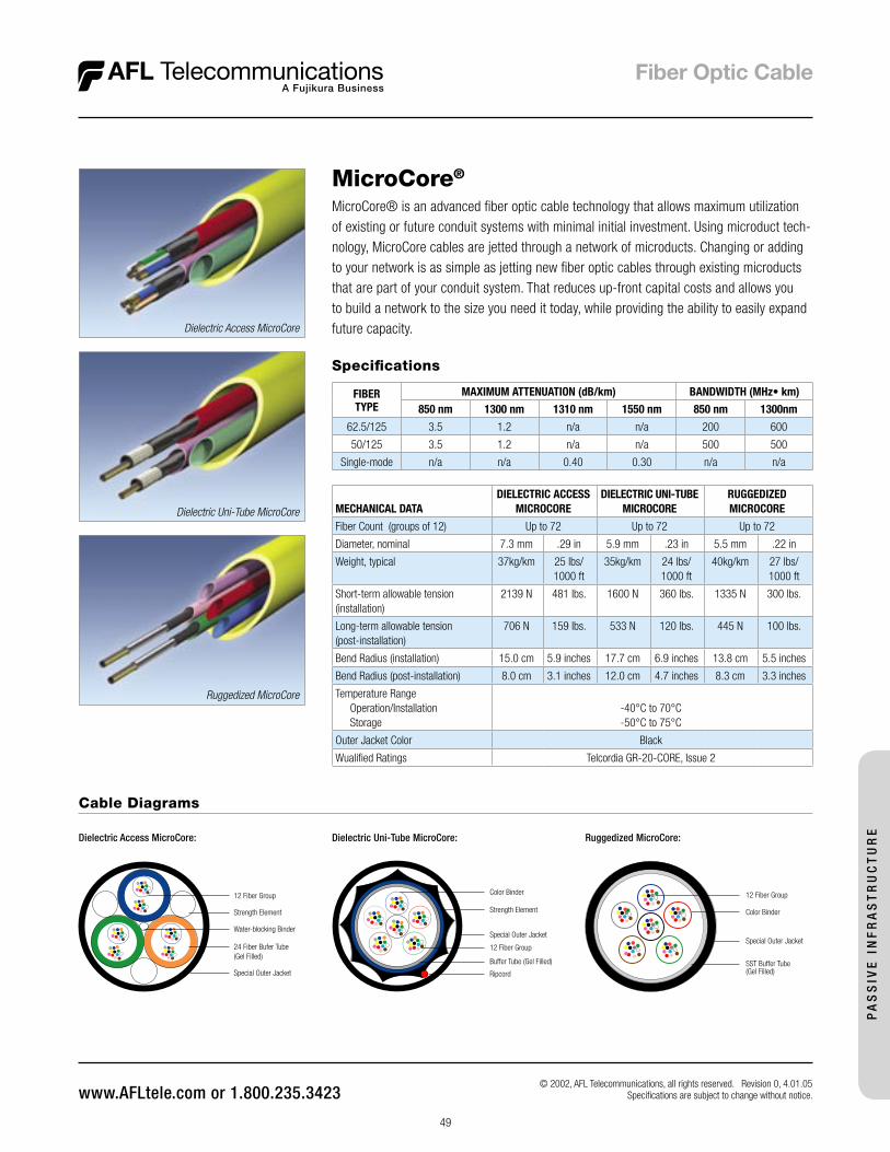
49
© 2002, AFL Telecommunications, all rights reserved. Revision 0, 4.01.05 Specifications are subject to change without notice.
MicroCore® is an advanced fiber optic cable technology that allows maximum utilization of existing or future conduit systems with minimal initial investment. Using microduct tech-nology, MicroCore cables are jetted through a network of microducts. Changing or adding to your network is as simple as jetting new fiber optic cables through existing microducts that are part of your conduit system. That reduces up-front capital costs and allows you to build a network to the size you need it today, while providing the ability to easily expand future capacity.
MicroCore®
Dielectric Access MicroCore
Dielectric Uni-Tube MicroCore
Ruggedized MicroCore
PA
SS
IVE
IN
FR
AS
TR
UC
TU
RE
Specifications
FIBERTYPE
MAXIMUM ATTENUATION (dB/km) BANDWIDTH (MHz• km)
850 nm 1300 nm 1310 nm 1550 nm 850 nm 1300nm
62.5/125 3.5 1.2 n/a n/a 200 600
50/125 3.5 1.2 n/a n/a 500 500
Single-mode n/a n/a 0.40 0.30 n/a n/a
Dielectric Uni-Tube MicroCore:
Color Binder
Ripcord
12 Fiber Group
Strength Element
Special Outer Jacket
Buffer Tube (Gel Filled)
Dielectric Access MicroCore:
12 Fiber Group
Strength Element
Water-blocking Binder
24 Fiber Bufer Tube(Gel Filled)
Special Outer Jacket
Cable Diagrams
Color Binder
12 Fiber Group
Special Outer Jacket
SST Buffer Tube(Gel Filled)
Ruggedized MicroCore:
MECHANICAL DATADIELECTRIC ACCESS
MICROCOREDIELECTRIC UNI-TUBE
MICROCORERUGGEDIZED MICROCORE
Fiber Count (groups of 12) Up to 72 Up to 72 Up to 72
Diameter, nominal 7.3 mm .29 in 5.9 mm .23 in 5.5 mm .22 in
Weight, typical 37kg/km 25 lbs/1000 ft
35kg/km 24 lbs/1000 ft
40kg/km 27 lbs/1000 ft
Short-term allowable tension(installation)
2139 N 481 lbs. 1600 N 360 lbs. 1335 N 300 lbs.
Long-term allowable tension(post-installation)
706 N 159 lbs. 533 N 120 lbs. 445 N 100 lbs.
Bend Radius (installation) 15.0 cm 5.9 inches 17.7 cm 6.9 inches 13.8 cm 5.5 inches
Bend Radius (post-installation) 8.0 cm 3.1 inches 12.0 cm 4.7 inches 8.3 cm 3.3 inches
Temperature Range Operation/Installation Storage
-40°C to 70°C-50°C to 75°C
Outer Jacket Color Black
Wualified Ratings Telcordia GR-20-CORE, Issue 2
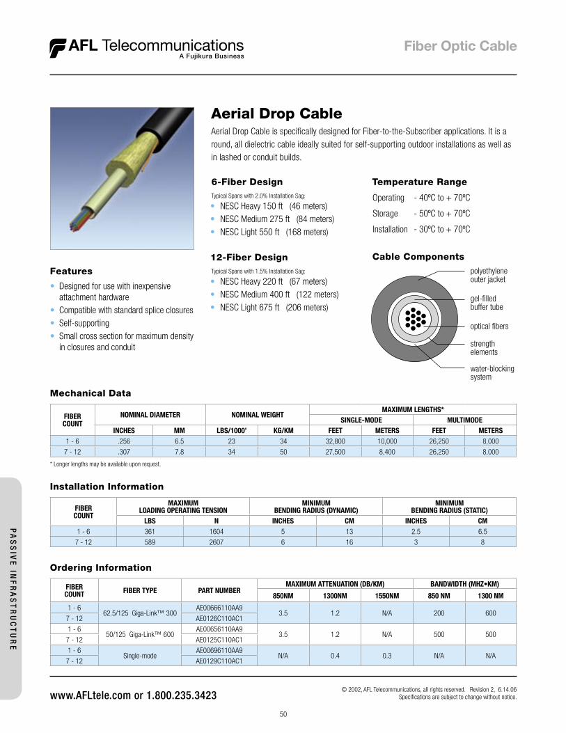
50
© 2002, AFL Telecommunications, all rights reserved. Revision 2, 6.14.06 Specifications are subject to change without notice.
6-Fiber DesignTypical Spans with 2.0% Installation Sag:
• NESC Heavy 150 ft (46 meters)• NESC Medium 275 ft (84 meters)• NESC Light 550 ft (168 meters)
Temperature Range
Operating - 40ºC to + 70ºC
Storage - 50ºC to + 70ºC
Installation - 30ºC to + 70ºC
Aerial Drop Cable
Cable Components
Mechanical Data
FIBERCOUNT
NOMINAL DIAMETER NOMINAL WEIGHTMAXIMUM LENGTHS*
SINGLE-MODE MULTIMODEINCHES MM LBS/1000’ KG/KM FEET METERS FEET METERS
1 - 6 .256 6.5 23 34 32,800 10,000 26,250 8,000
7 - 12 .307 7.8 34 50 27,500 8,400 26,250 8,000
* Longer lengths may be available upon request.
Installation Information
FIBERCOUNT
MAXIMUMLOADING OPERATING TENSION
MINIMUMBENDING RADIUS (DYNAMIC)
MINIMUMBENDING RADIUS (STATIC)
LBS N INCHES CM INCHES CM1 - 6 361 1604 5 13 2.5 6.5
7 - 12 589 2607 6 16 3 8
Features
• Designed for use with inexpensive attachment hardware
• Compatible with standard splice closures• Self-supporting• Small cross section for maximum density
in closures and conduit ����������������
���������������������
������������������������
��������������
��������������������
Aerial Drop Cable is specifically designed for Fiber-to-the-Subscriber applications. It is a round, all dielectric cable ideally suited for self-supporting outdoor installations as well as in lashed or conduit builds.
Ordering Information
FIBERCOUNT FIBER TYPE PART NUMBER
MAXIMUM ATTENUATION (DB/KM) BANDWIDTH (MHZ•KM)
850NM 1300NM 1550NM 850 NM 1300 NM
1 - 662.5/125 Giga-Link™ 300
AE00666110AA93.5 1.2 N/A 200 600
7 - 12 AE0126C110AC1
1 - 650/125 Giga-Link™ 600
AE00656110AA93.5 1.2 N/A 500 500
7 - 12 AE0125C110AC1
1 - 6Single-mode
AE00696110AA9N/A 0.4 0.3 N/A N/A
7 - 12 AE0129C110AC1
12-Fiber DesignTypical Spans with 1.5% Installation Sag:
• NESC Heavy 220 ft (67 meters)• NESC Medium 400 ft (122 meters)• NESC Light 675 ft (206 meters)
PA
SS
IVE
INF
RA
ST
RU
CT
UR
E
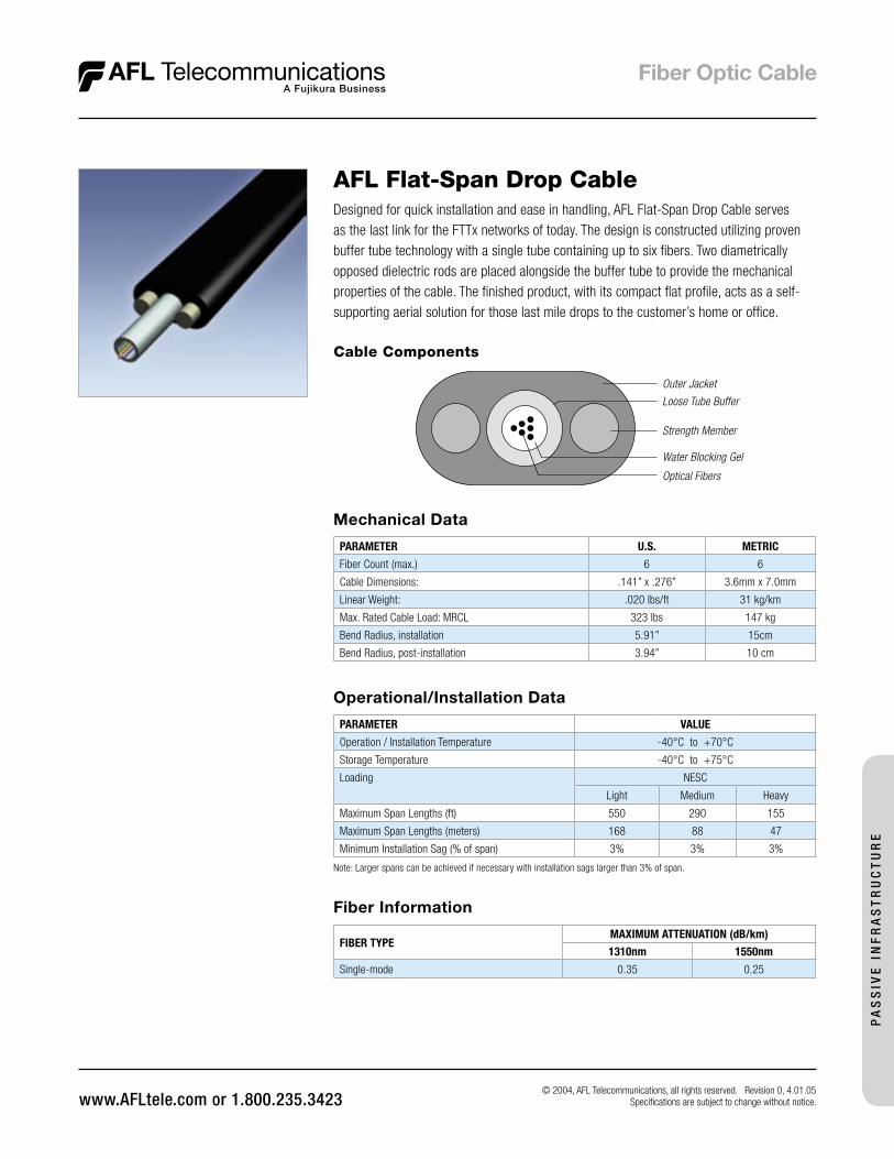
© 2004, AFL Telecommunications, all rights reserved. Revision 0, 4.01.05 Specifications are subject to change without notice.
AFL Flat-Span Drop Cable
Cable Components
Designed for quick installation and ease in handling, AFL Flat-Span Drop Cable serves as the last link for the FTTx networks of today. The design is constructed utilizing proven buffer tube technology with a single tube containing up to six fibers. Two diametrically opposed dielectric rods are placed alongside the buffer tube to provide the mechanical properties of the cable. The finished product, with its compact flat profile, acts as a self-supporting aerial solution for those last mile drops to the customer’s home or office.
Operational/Installation Data
PARAMETER VALUE
Operation / Installation Temperature -40°C to +70°C
Storage Temperature -40°C to +75°C
Loading NESC
Light Medium Heavy
Maximum Span Lengths (ft) 550 290 155
Maximum Span Lengths (meters) 168 88 47
Minimum Installation Sag (% of span) 3% 3% 3%
Note: Larger spans can be achieved if necessary with installation sags larger than 3% of span.
Mechanical Data
PARAMETER U.S. METRIC
Fiber Count (max.) 6 6
Cable Dimensions: .141” x .276” 3.6mm x 7.0mm
Linear Weight: .020 lbs/ft 31 kg/km
Max. Rated Cable Load: MRCL 323 lbs 147 kg
Bend Radius, installation 5.91” 15cm
Bend Radius, post-installation 3.94” 10 cm
Fiber Information
FIBER TYPEMAXIMUM ATTENUATION (dB/km)
1310nm 1550nm
Single-mode 0.35 0.25
PA
SS
IVE
IN
FR
AS
TR
UC
TU
RE
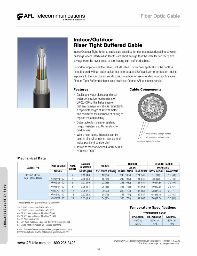
52
© 2002-2006, AFL Telecommunications, all rights reserved. Revision 1, 8.23.06 Specifications are subject to change without notice.
Indoor/Outdoor Riser Tight Buffered CableIndoor/Outdoor Tight Buffered cables are specified for campus network cabling between buildings where interbuilding lengths are short enough that the installer can recognize savings from the lower costs of terminating tight buffered cables.
For indoor applications the cable is OFNR listed. For outdoor applications the cable is manufactured with an outer jacket that incorporates a UV stabilizer for protection against exposure to the sun plus an anti-fungus protection for use in underground applications. Plenum Tight Buffered cable is also available. Contact AFL customer service.
Features
• Cables are water blocked and meet water penetration requirements of GR-20-CORE (this helps ensure that any damage to cable is restricted to a repairable length of several meters and minimizes the likelihood of having to replace the entire cable)
• Outer jacket is moisture-resistent, fungus-resistent and UV resistant for outdoor use
• With a riser rating, this cable can be used in all environments: riser, general inside plant and outside plant
• Tested to meet or exceed EIA/TIA 568-A / GR-409-CORE
Mechanical Data
CABLE TYPEPART NUMBER FIBER
COUNT
NOMINAL DIAMETER WEIGHT
TENSION BENDING RADIUSLBS (N) INCHES (CM)
PLENUM INCHES (MM) LBS/1000FT (KG/KM) INSTALLATION LONG TERM INSTALLATION LONG TERMIndoor/Outdoor
Tight Buffered Cable 2 0.19 (4.8) 18 (27) 243 (1082) 121 (541) 3.8 (9.6) 1.9 (4.8)
KR004*481001 4 0.19 (4.8) 18 (27) 243 (1082) 121 (541) 3.8 (96) 1.9 (4.8)
KR006*591001 6 0.23 (5.9) 22 (33) 243 (1082) 121 (541) 4.6 (11.8) 2.3 (5.9)
KR008*641001 8 0.25 (6.4) 26 (38) 388 (1726) 194 (863) 5.0 (12.8) 2.5 (6.4)
KR012*741001 12 0.29 (7.4) 39 (59) 388 (1726) 194 (863) 5.8 (14.8) 2.9 (7.4)
KR018*821001 18 0.32 (8.2) 50 (75) 398 (1774) 199 (887) 6.4 (16.4) 3.2 (8.2)
KR024*891001 24 0.35 (8.9) 54 (80) 398 (1774) 199 (887) 7.0 (17.8) 3.5 (8.9)
* Please specify fiber type when ordering (see below)
5 = 50/125µm multimode GIGA-Link™ 600 7 = 50/125µm multimode GIGA-Link™ 2000 6 = 62.5/125µm multimode GIGA-Link™ 3008 = 62.5/125µm multimode GIGA-Link™ 10009 = 9/125µm single-modeL = 50/125µm multimode Laser-Link 300 for 10 Gigabit EthernetK = Single-mode Futureguide SR-15e Bend Insensitive
Contact Customer Service for special fiber types/performance needs.Standard jacket color is black. Other colors available by request.
Cable Components
������������������������������
������������������������������
��������������������
Temperature Specifications
TEMPERATURE RANGEOPERATING INSTALLATION STORAGE
-40°C to +75°C
-10°C to +70°C
-40°C to +75°C
PA
SS
IVE
INF
RA
ST
RU
CT
UR
E
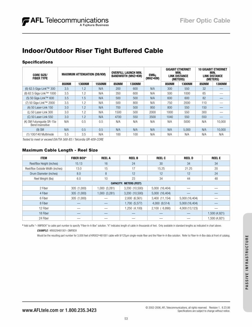
53
© 2002-2006, AFL Telecommunications, all rights reserved. Revision 1, 8.23.06 Specifications are subject to change without notice.
Indoor/Outdoor Riser Tight Buffered Cable
* Add suffix “– XMFBOX” to cable part number to specify “Fiber-In-A-Box” solution. “X” indicates length of cable in thousands of feet. Only available in standard lengths as indicated in chart above.
EXAMPLE: KR0029481001–3MFBOX Would be the resulting part number for 3,000 feet of KR002*481001 cable with 9/125µm single-mode fiber and the Fiber-In-A-Box solution. Refer to Fiber-In-A-Box data at front of catalog.
Maximum Cable Length - Reel Size
ITEM FIBER BOX* REEL A REEL B REEL C REEL D REEL E
Reel/Box Height (inches) 15.13 16 24 30 34 34
Reel/Box Outside Width (inches) 13.0 15 17 15.25 21.25 20
Drum Diameter (inches) 8.0 8 12 12 12 24
Reel Weight (lbs) 6.0 10 23 34 44 48CAPACITY: METERS (FEET)
2 Fiber 305 (1,000) 1,000 (3,281) 3,200 (10,500) 5,000 (16,404) — —
4 Fiber 305 (1,000) 1,000 (3,281) 3,200 (10,500) 5,000 (16,404) — —
6 Fiber 305 (1,000) — 2,000 (6,561) 3,400 (11,154) 5,000 (16,404) —
8 Fiber — — 1,700 (5,577) 4,000 (9,514) 5,000 (16,404) —
12 Fiber — — 1,250 (4,100) 2,100 ( 6,890) 4,000 (13,123) —
18 Fiber — — — — — 1,500 (4,921)
24 Fiber — — — — — 1,500 (4,921)
Specifications
CORE SIZE/FIBER TYPE
MAXIMUM ATTENUATION (DB/KM) OVERFILL LAUNCH MIN.BANDWIDTH (MHZ•KM) EMBc
(MHZ•KM)
GIGABIT ETHERNET MIN.
LINK DISTANCE (METERS)
10 GIGABIT ETHERNET MIN.
LINK DISTANCE (METERS)
850NM 1300NM 1550NM 850NM 1300NM 850NM 1300NM 850NM 1300NM(6) 62.5 Giga-Link™ 300 3.5 1.2 N/A 200 600 N/A 300 550 32 —
(8) 62.5 Giga-Link™ 1000 3.5 1.2 N/A 350 600 N/A 500 1000 65 —
(5) 50 Giga-Link™ 600 3.5 1.5 N/A 500 500 N/A 600 600 82 —
(7) 50 Giga-Link™ 2000 3.5 1.2 N/A 500 800 N/A 750 2000 110 —
(A) 50 Laser-Link 150 3.0 1.2 N/A 700 500 950 800 550 150 —
(L) 50 Laser-Link 300 3.0 1.2 N/A 1500 500 2000 1000 550 300 —
(C) 50 Laser-Link 550 3.0 1.2 N/A 4700 550 3500 1040 550 550 —
(K) SM Futureguide SR-15e Bend Insensitive
N/A 0.5 0.5 N/A N/A N/A N/A 5000 N/A 10,000
(9) SM N/A 0.5 0.5 N/A N/A N/A N/A 5,000 N/A 10,000
(1) 100/140 Multimode 5.5 3.5 N/A 100 100 N/A N/A N/A N/A N/A
Tested to meet or exceed EIA/TIA 568-B3 / Telcordia GR-409-CORE
PA
SS
IVE
IN
FR
AS
TR
UC
TU
RE
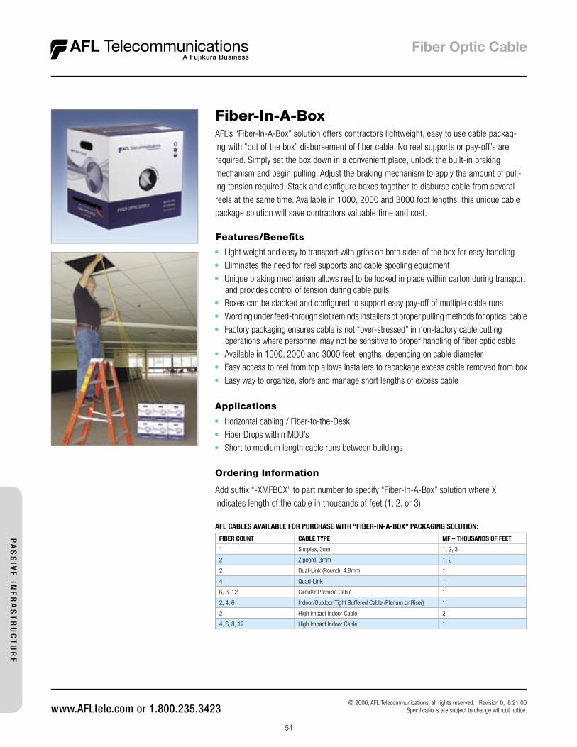
54
© 2006, AFL Telecommunications, all rights reserved. Revision 0, 8.21.06 Specifi cations are subject to change without notice.
Fiber-In-A-BoxAFL’s “Fiber-In-A-Box” solution offers contractors lightweight, easy to use cable packag-ing with “out of the box” disbursement of fi ber cable. No reel supports or pay-off’s are required. Simply set the box down in a convenient place, unlock the built-in braking mechanism and begin pulling. Adjust the braking mechanism to apply the amount of pull-ing tension required. Stack and confi gure boxes together to disburse cable from several reels at the same time. Available in 1000, 2000 and 3000 foot lengths, this unique cable package solution will save contractors valuable time and cost.
Applications
• Horizontal cabling / Fiber-to-the-Desk • Fiber Drops within MDU’s• Short to medium length cable runs between buildings
Ordering Information
Add suffi x “-XMFBOX” to part number to specify “Fiber-In-A-Box” solution where X indicates length of the cable in thousands of feet (1, 2, or 3).
AFL CABLES AVAILABLE FOR PURCHASE WITH “FIBER-IN-A-BOX” PACKAGING SOLUTION:
FIBER COUNT CABLE TYPE MF – THOUSANDS OF FEET
1 Simplex, 3mm 1, 2, 3
2 Zipcord, 3mm 1, 2
2 Dual-Link (Round), 4.8mm 1
4 Quad-Link 1
6, 8, 12 Circular Premise Cable 1
2, 4, 6 Indoor/Outdoor Tight Buffered Cable (Plenum or Riser) 1
2 High Impact Indoor Cable 2
4, 6, 8, 12 High Impact Indoor Cable 1
Features/Benefi ts
• Light weight and easy to transport with grips on both sides of the box for easy handling• Eliminates the need for reel supports and cable spooling equipment• Unique braking mechanism allows reel to be locked in place within carton during transport
and provides control of tension during cable pulls• Boxes can be stacked and confi gured to support easy pay-off of multiple cable runs• Wording under feed-through slot reminds installers of proper pulling methods for optical cable• Factory packaging ensures cable is not “over-stressed” in non-factory cable cutting
operations where personnel may not be sensitive to proper handling of fi ber optic cable• Available in 1000, 2000 and 3000 feet lengths, depending on cable diameter• Easy access to reel from top allows installers to repackage excess cable removed from box• Easy way to organize, store and manage short lengths of excess cable
PA
SS
IVE
INF
RA
ST
RU
CT
UR
E
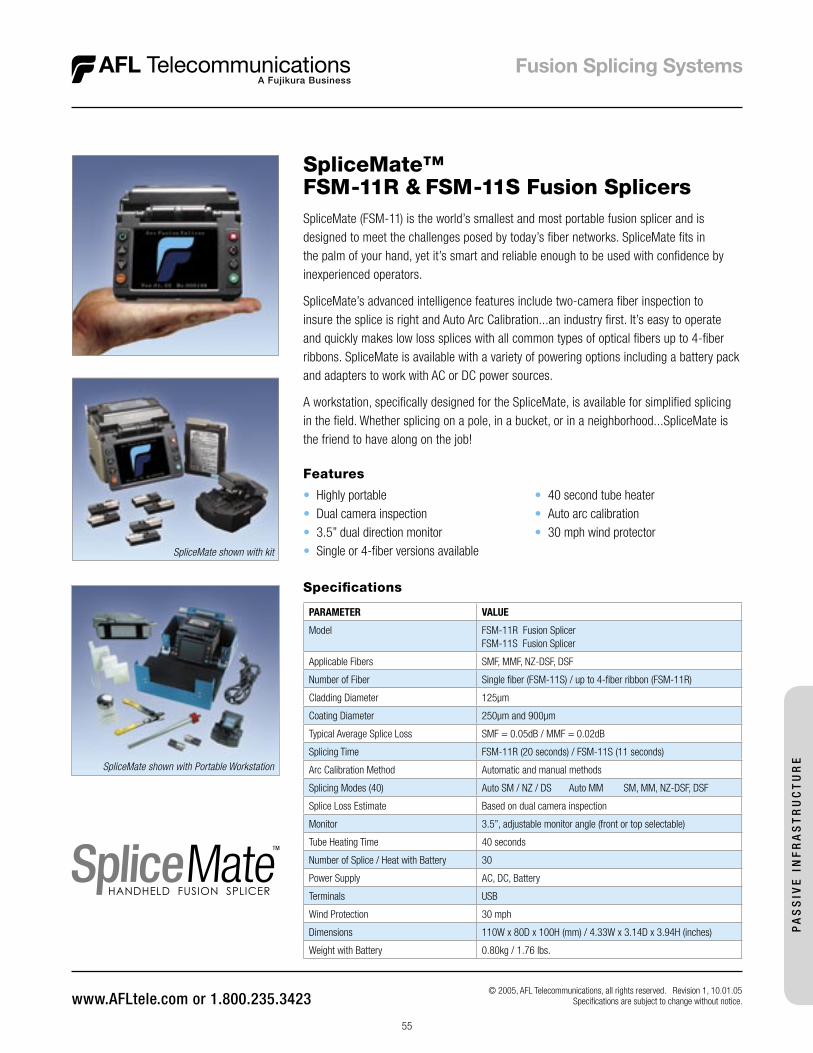
55
Specifications
PARAMETER VALUE
Model FSM-11R Fusion SplicerFSM-11S Fusion Splicer
Applicable Fibers SMF, MMF, NZ-DSF, DSF
Number of Fiber Single fiber (FSM-11S) / up to 4-fiber ribbon (FSM-11R)
Cladding Diameter 125µm
Coating Diameter 250µm and 900µm
Typical Average Splice Loss SMF = 0.05dB / MMF = 0.02dB
Splicing Time FSM-11R (20 seconds) / FSM-11S (11 seconds)
Arc Calibration Method Automatic and manual methods
Splicing Modes (40) Auto SM / NZ / DS Auto MM SM, MM, NZ-DSF, DSF
Splice Loss Estimate Based on dual camera inspection
Monitor 3.5”, adjustable monitor angle (front or top selectable)
Tube Heating Time 40 seconds
Number of Splice / Heat with Battery 30
Power Supply AC, DC, Battery
Terminals USB
Wind Protection 30 mph
Dimensions 110W x 80D x 100H (mm) / 4.33W x 3.14D x 3.94H (inches)
Weight with Battery 0.80kg / 1.76 lbs.
SpliceMate (FSM-11) is the world’s smallest and most portable fusion splicer and is designed to meet the challenges posed by today’s fiber networks. SpliceMate fits in the palm of your hand, yet it’s smart and reliable enough to be used with confidence by inexperienced operators.
SpliceMate’s advanced intelligence features include two-camera fiber inspection to insure the splice is right and Auto Arc Calibration...an industry first. It’s easy to operate and quickly makes low loss splices with all common types of optical fibers up to 4-fiber ribbons. SpliceMate is available with a variety of powering options including a battery pack and adapters to work with AC or DC power sources.
A workstation, specifically designed for the SpliceMate, is available for simplified splicing in the field. Whether splicing on a pole, in a bucket, or in a neighborhood...SpliceMate is the friend to have along on the job!
Features
• Highly portable• Dual camera inspection• 3.5” dual direction monitor• Single or 4-fiber versions available
• 40 second tube heater• Auto arc calibration• 30 mph wind protector
SpliceMate™ FSM-11R & FSM-11S Fusion Splicers
© 2005, AFL Telecommunications, all rights reserved. Revision 1, 10.01.05 Specifications are subject to change without notice.
SpliceMate shown with kit
SpliceMate shown with Portable Workstation
PA
SS
IVE
IN
FR
AS
TR
UC
TU
RE
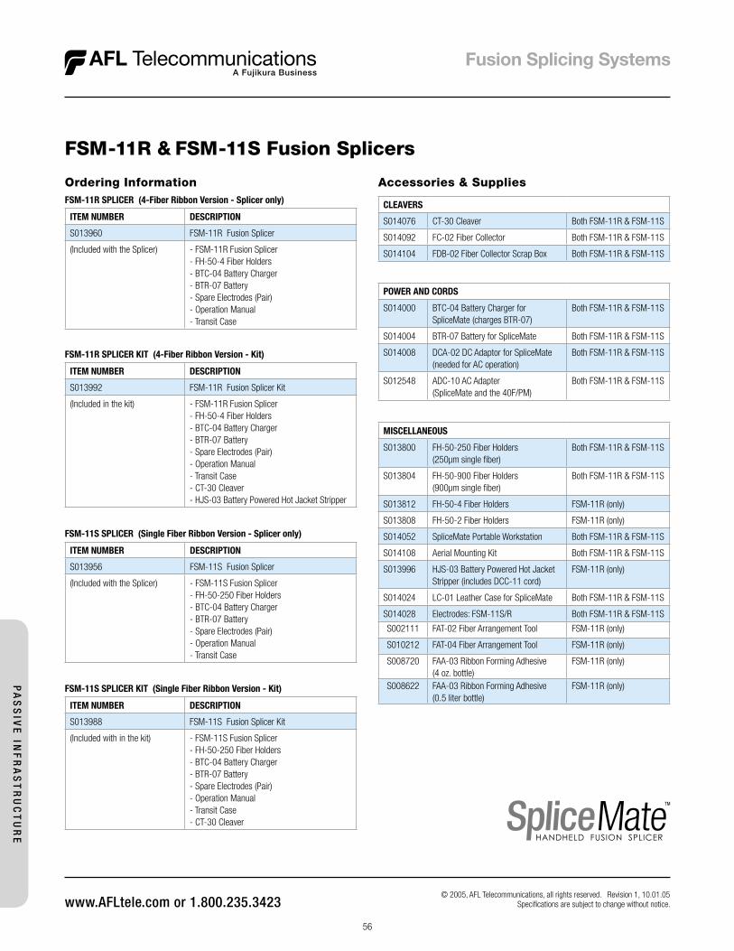
56
Ordering InformationFSM-11R SPLICER (4-Fiber Ribbon Version - Splicer only)
ITEM NUMBER DESCRIPTION
S013960 FSM-11R Fusion Splicer
(Included with the Splicer) - FSM-11R Fusion Splicer- FH-50-4 Fiber Holders- BTC-04 Battery Charger- BTR-07 Battery- Spare Electrodes (Pair)- Operation Manual- Transit Case
FSM-11R SPLICER KIT (4-Fiber Ribbon Version - Kit)
ITEM NUMBER DESCRIPTION
S013992 FSM-11R Fusion Splicer Kit
(Included in the kit) - FSM-11R Fusion Splicer- FH-50-4 Fiber Holders- BTC-04 Battery Charger- BTR-07 Battery- Spare Electrodes (Pair)- Operation Manual- Transit Case- CT-30 Cleaver- HJS-03 Battery Powered Hot Jacket Stripper
FSM-11S SPLICER (Single Fiber Ribbon Version - Splicer only)
ITEM NUMBER DESCRIPTION
S013956 FSM-11S Fusion Splicer
(Included with the Splicer) - FSM-11S Fusion Splicer- FH-50-250 Fiber Holders- BTC-04 Battery Charger- BTR-07 Battery- Spare Electrodes (Pair)- Operation Manual- Transit Case
FSM-11S SPLICER KIT (Single Fiber Ribbon Version - Kit)
ITEM NUMBER DESCRIPTION
S013988 FSM-11S Fusion Splicer Kit
(Included with in the kit) - FSM-11S Fusion Splicer- FH-50-250 Fiber Holders- BTC-04 Battery Charger- BTR-07 Battery- Spare Electrodes (Pair)- Operation Manual- Transit Case- CT-30 Cleaver
Accessories & Supplies
CLEAVERS
S014076 CT-30 Cleaver Both FSM-11R & FSM-11S
S014092 FC-02 Fiber Collector Both FSM-11R & FSM-11S
S014104 FDB-02 Fiber Collector Scrap Box Both FSM-11R & FSM-11S
© 2005, AFL Telecommunications, all rights reserved. Revision 1, 10.01.05 Specifications are subject to change without notice.
MISCELLANEOUS
S013800 FH-50-250 Fiber Holders (250µm single fiber)
Both FSM-11R & FSM-11S
S013804 FH-50-900 Fiber Holders (900µm single fiber)
Both FSM-11R & FSM-11S
S013812 FH-50-4 Fiber Holders FSM-11R (only)
S013808 FH-50-2 Fiber Holders FSM-11R (only)
S014052 SpliceMate Portable Workstation Both FSM-11R & FSM-11S
S014108 Aerial Mounting Kit Both FSM-11R & FSM-11S
S013996 HJS-03 Battery Powered Hot Jacket Stripper (includes DCC-11 cord)
FSM-11R (only)
S014024 LC-01 Leather Case for SpliceMate Both FSM-11R & FSM-11S
S014028 Electrodes: FSM-11S/R Both FSM-11R & FSM-11S
S002111 FAT-02 Fiber Arrangement Tool FSM-11R (only)
S010212 FAT-04 Fiber Arrangement Tool FSM-11R (only)
S008720 FAA-03 Ribbon Forming Adhesive (4 oz. bottle)
FSM-11R (only)
S008622 FAA-03 Ribbon Forming Adhesive (0.5 liter bottle)
FSM-11R (only)
FSM-11R & FSM-11S Fusion Splicers
POWER AND CORDS
S014000 BTC-04 Battery Charger for SpliceMate (charges BTR-07)
Both FSM-11R & FSM-11S
S014004 BTR-07 Battery for SpliceMate Both FSM-11R & FSM-11S
S014008 DCA-02 DC Adaptor for SpliceMate (needed for AC operation)
Both FSM-11R & FSM-11S
S012548 ADC-10 AC Adapter (SpliceMate and the 40F/PM)
Both FSM-11R & FSM-11S
PA
SS
IVE
INF
RA
ST
RU
CT
UR
E
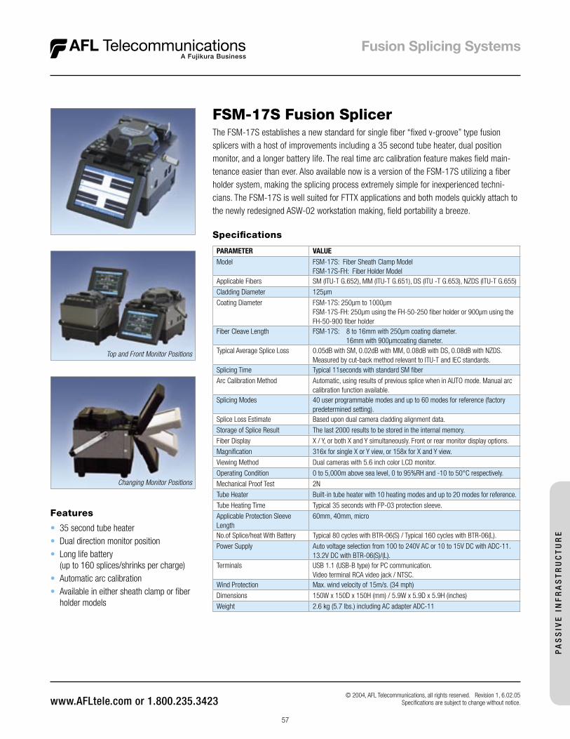
57
Features
• 35 second tube heater• Dual direction monitor position• Long life battery
(up to 160 splices/shrinks per charge)• Automatic arc calibration• Available in either sheath clamp or fiber
holder models
FSM-17S Fusion SplicerThe FSM-17S establishes a new standard for single fiber “fixed v-groove” type fusion splicers with a host of improvements including a 35 second tube heater, dual position monitor, and a longer battery life. The real time arc calibration feature makes field main-tenance easier than ever. Also available now is a version of the FSM-17S utilizing a fiber holder system, making the splicing process extremely simple for inexperienced techni-cians. The FSM-17S is well suited for FTTX applications and both models quickly attach to the newly redesigned ASW-02 workstation making, field portability a breeze.
Specifications
PARAMETER VALUEModel FSM-17S: Fiber Sheath Clamp Model
FSM-17S-FH: Fiber Holder ModelApplicable Fibers SM (ITU-T G.652), MM (ITU-T G.651), DS (ITU -T G.653), NZDS (ITU-T G.655)
Cladding Diameter 125µm
Coating Diameter FSM-17S: 250µm to 1000µmFSM-17S-FH: 250µm using the FH-50-250 fiber holder or 900µm using the FH-50-900 fiber holder
Fiber Cleave Length FSM-17S: 8 to 16mm with 250µm coating diameter. 16mm with 900µmcoating diameter.
Typical Average Splice Loss 0.05dB with SM, 0.02dB with MM, 0.08dB with DS, 0.08dB with NZDS. Measured by cut-back method relevant to ITU-T and IEC standards.
Splicing Time Typical 11seconds with standard SM fiber
Arc Calibration Method Automatic, using results of previous splice when in AUTO mode. Manual arc calibration function available.
Splicing Modes 40 user programmable modes and up to 60 modes for reference (factory predetermined setting).
Splice Loss Estimate Based upon dual camera cladding alignment data.
Storage of Splice Result The last 2000 results to be stored in the internal memory.
Fiber Display X / Y, or both X and Y simultaneously. Front or rear monitor display options.
Magnification 316x for single X or Y view, or 158x for X and Y view.
Viewing Method Dual cameras with 5.6 inch color LCD monitor.
Operating Condition 0 to 5,000m above sea level, 0 to 95%RH and -10 to 50°C respectively.
Mechanical Proof Test 2N
Tube Heater Built-in tube heater with 10 heating modes and up to 20 modes for reference.
Tube Heating Time Typical 35 seconds with FP-03 protection sleeve.
Applicable Protection Sleeve Length
60mm, 40mm, micro
No.of Splice/heat With Battery Typical 80 cycles with BTR-06(S) / Typical 160 cycles with BTR-06(L).
Power Supply Auto voltage selection from 100 to 240V AC or 10 to 15V DC with ADC-11. 13.2V DC with BTR-06(S)/(L).
Terminals USB 1.1 (USB-B type) for PC communication.Video terminal RCA video jack / NTSC.
Wind Protection Max. wind velocity of 15m/s. (34 mph)
Dimensions 150W x 150D x 150H (mm) / 5.9W x 5.9D x 5.9H (inches)
Weight 2.6 kg (5.7 lbs.) including AC adapter ADC-11
Changing Monitor Positions
Top and Front Monitor Positions
© 2004, AFL Telecommunications, all rights reserved. Revision 1, 6.02.05 Specifications are subject to change without notice.
PA
SS
IVE
IN
FR
AS
TR
UC
TU
RE
58
Ordering Information
DESCRIPTION PART #
FSM-17S Fusion Splicer (machine only)Each FSM-17S Fusion Splicer includes; ADC-11 AC adapter/battery charger, AC cord, carrying strap, spare electrodes (pair), instruction manual, transit case.
S013612
FSM-17S Fusion Splicer KitThe kit includes a CT-30A Cleaver in addition to the FSM-17S, ADC-11 AC adapter/battery charger, AC cord, carrying strap, spare electrodes (pair), instruction manual, transit case.
S013616
FSM-17S Fusion Splicer Kit with Battery and Charge CordThe kit includes a BTR-06(S) battery, DCC-10 battery charge cord, and CT-30A Cleaver in addition to the FSM-17S, ADC-11 AC adapter/battery charger, AC cord, carrying strap, spare electrodes (pair), instruction manual, transit case.
S013880
FSM-17S-FH Fusion Splicer (machine only)Each FSM-17S-FH Fusion Splicer includes; FH-50-250 Fiber Holder (1 pair), FH-50-900 Fiber Holder (1 pair), ADC-11 AC adapter/battery charger, AC cord, carrying strap, spare electrodes (pair), instruction manual, transit case.
S013832
FSM-17S-FH Fusion Splicer KitThe kit includes a CT-30 Cleaver in addition to the FSM-17FH, FH-50-250 Fiber Holder (1 pair), FH-50-900 Fiber Holder (1 pair), ADC-11 AC adapter/battery charger, AC cord, carrying strap, spare electrodes (pair), instruction manual, transit case.
S013836
FSM-17S Fusion Splicer
Accessories Recommended for FSM-17S
DESCRIPTION PART #CleaversCT-30 Cleaver S014076
CT-30A Cleaver S014080
Fiber Holders (pairsFH-50-250 (250 µm coated single fiber) S013800
FH-50-900 (900 µm jacketed single fiber) S013804
Batteries & Power CordsADC-11 AC Adapter/Battery Charger S013516
BTR-06S Battery (80 splice/heating cycles) S013520
BTR-06L Battery (160 splice/heating cycles) S013528
DCC-10 Power Cord(connects ADC-11 to BTR-06S or BTR-06L)
S013524
DCC-12 Power Cord(connects ADC-11 to cigarette lighter socket)
S013552
DCC-13 Power Cord(connects ADC-11 to power source via alligator clips)
S013556
MiscellaneousELCT2-20A Electrodes (17S) S013532
ASW-02 Aerial Workstation S010532
WT-6 Work Table S013536
WTS-06 Work Table Support S013544
MGS-05 Magnifier S013548
JP-04 Splice Sleeve Cooling Tray S013628
Transit Case (17S) S013884
© 2004, AFL Telecommunications, all rights reserved. Revision 1, 6.02.05 Specifications are subject to change without notice.
PA
SS
IVE
INF
RA
ST
RU
CT
UR
E
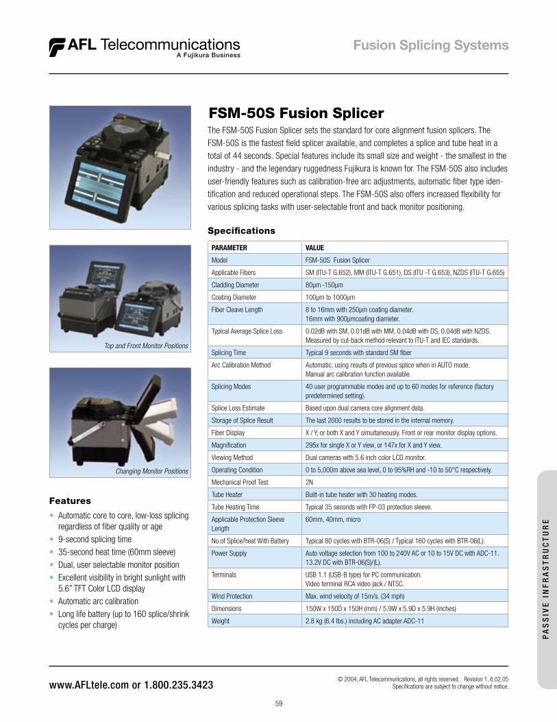
59
Features
• Automatic core to core, low-loss splicing regardless of fiber quality or age
• 9-second splicing time• 35-second heat time (60mm sleeve)• Dual, user selectable monitor position • Excellent visibility in bright sunlight with
5.6” TFT Color LCD display• Automatic arc calibration• Long life battery (up to 160 splice/shrink
cycles per charge)
FSM-50S Fusion SplicerThe FSM-50S Fusion Splicer sets the standard for core alignment fusion splicers. The FSM-50S is the fastest field splicer available, and completes a splice and tube heat in a total of 44 seconds. Special features include its small size and weight - the smallest in the industry - and the legendary ruggedness Fujikura is known for. The FSM-50S also includes user-friendly features such as calibration-free arc adjustments, automatic fiber type iden-tification and reduced operational steps. The FSM-50S also offers increased flexibility for various splicing tasks with user-selectable front and back monitor positioning.
Changing Monitor Positions
Top and Front Monitor Positions
Specifications
PARAMETER VALUE
Model FSM-50S Fusion Splicer
Applicable Fibers SM (ITU-T G.652), MM (ITU-T G.651), DS (ITU -T G.653), NZDS (ITU-T G.655)
Cladding Diameter 80µm -150µm
Coating Diameter 100µm to 1000µm
Fiber Cleave Length 8 to 16mm with 250µm coating diameter.16mm with 900µmcoating diameter.
Typical Average Splice Loss 0.02dB with SM, 0.01dB with MM, 0.04dB with DS, 0.04dB with NZDS. Measured by cut-back method relevant to ITU-T and IEC standards.
Splicing Time Typical 9 seconds with standard SM fiber
Arc Calibration Method Automatic, using results of previous splice when in AUTO mode. Manual arc calibration function available.
Splicing Modes 40 user programmable modes and up to 60 modes for reference (factory predetermined setting).
Splice Loss Estimate Based upon dual camera core alignment data.
Storage of Splice Result The last 2000 results to be stored in the internal memory.
Fiber Display X / Y, or both X and Y simultaneously. Front or rear monitor display options.
Magnification 295x for single X or Y view, or 147x for X and Y view.
Viewing Method Dual cameras with 5.6 inch color LCD monitor.
Operating Condition 0 to 5,000m above sea level, 0 to 95%RH and -10 to 50°C respectively.
Mechanical Proof Test 2N
Tube Heater Built-in tube heater with 30 heating modes.
Tube Heating Time Typical 35 seconds with FP-03 protection sleeve.
Applicable Protection Sleeve Length
60mm, 40mm, micro
No.of Splice/heat With Battery Typical 80 cycles with BTR-06(S) / Typical 160 cycles with BTR-06(L).
Power Supply Auto voltage selection from 100 to 240V AC or 10 to 15V DC with ADC-11. 13.2V DC with BTR-06(S)/(L).
Terminals USB 1.1 (USB-B type) for PC communication.Video terminal RCA video jack / NTSC.
Wind Protection Max. wind velocity of 15m/s. (34 mph)
Dimensions 150W x 150D x 150H (mm) / 5.9W x 5.9D x 5.9H (inches)
Weight 2.8 kg (6.4 lbs.) including AC adapter ADC-11
© 2004, AFL Telecommunications, all rights reserved. Revision 1, 6.02.05 Specifications are subject to change without notice.
PA
SS
IVE
IN
FR
AS
TR
UC
TU
RE
60
FSM-50S Fusion Splicer
Accessories Recommended for the FSM-50S
DESCRIPTION PART #
Cleavers
CT-30A Cleaver S014080
Batteries & Power Cords
ADC-11 AC Adapter/Battery Charger S013516
BTR-06S Battery (80 splice/heating cycles) S013520
BTR-06L Battery (160 splice/heating cycles) S013528
DCC-10 Power Cord(connects ADC-11 to BTR-06S or BTR-06L)
S013524
DCC-12 Power Cord(connects ADC-11 to cigarette lighter socket)
S013552
DCC-13 Power Cord(connects ADC-11 to power source via alligator clips)
S013556
Miscellaneous
ELCT2-20A Electrodes S013532
ASW-02 Splicing Workstation S010532
WT-6 Work Table S013536
WTS-06 Work Table Support S013544
JP-04 Splice Sleeve Cooling Tray S013628
50S Set Plate “B” (allows 10mm cleave of 900µm) (includes installation) S013564
Transit Case (50S) S013540
One year extended warranty S012996
Two year extended warranty S013000
Ordering Information
DESCRIPTION PART #
FSM-50S Fusion Splicer (Machine Only)Each FSM-50S Fusion Splicer comes with ADC-11 AC adapter/battery charger, AC cord, spare electrodes (pair), monitor cover, operation manual, and transit case.
S013510
FSM-50S Fusion Splicer Kit (includes cleaver)Each FSM-50S Fusion Splicer Kit includes: Fusion Splicer with ADC-11 AC adapter/battery charger, CT-30A Cleaver, AC cord, spare electrodes (pair), monitor cover, operation manual, and transit case.
S013512
© 2004, AFL Telecommunications, all rights reserved. Revision 1, 6.02.05 Specifications are subject to change without notice.
PA
SS
IVE
INF
RA
ST
RU
CT
UR
E
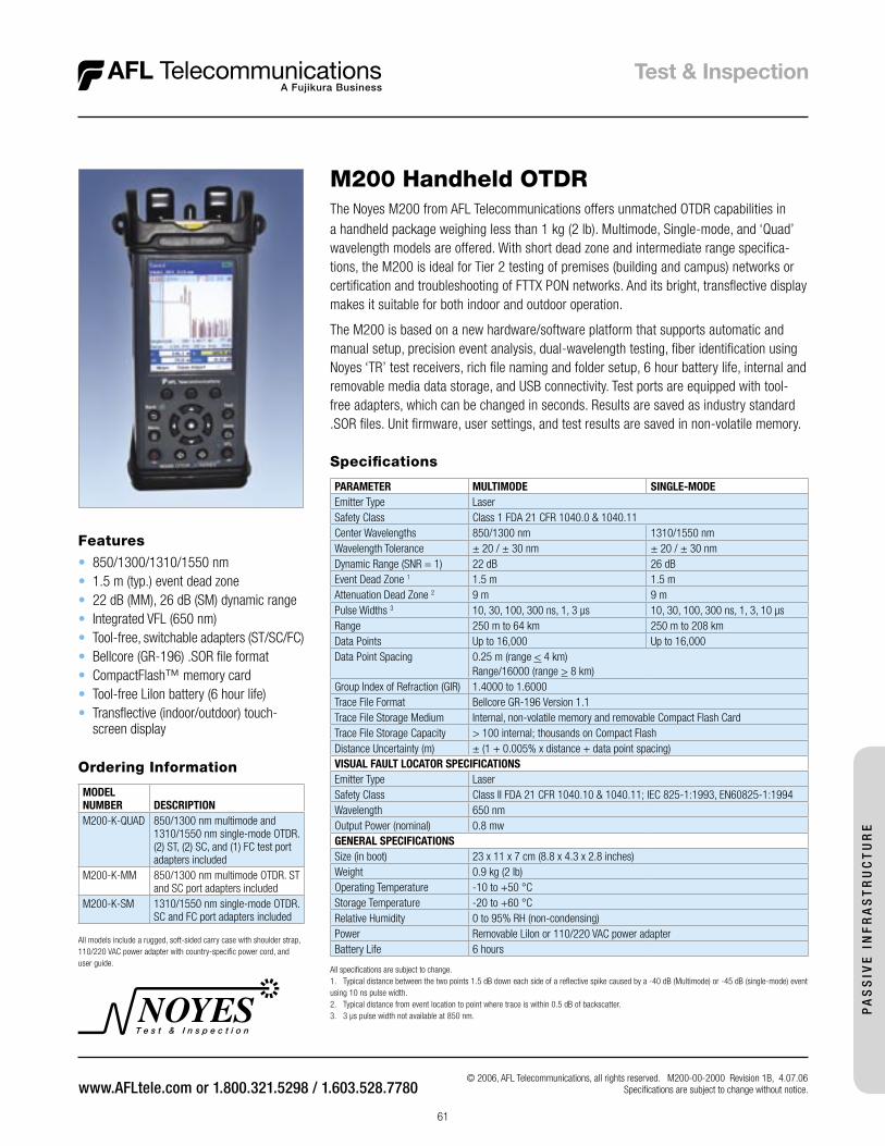
T e s t & I n s p e c t i o n
© 2006, AFL Telecommunications, all rights reserved. M200-00-2000 Revision 1B, 4.07.06 Specifications are subject to change without notice.
61
The Noyes M200 from AFL Telecommunications offers unmatched OTDR capabilities in a handheld package weighing less than 1 kg (2 lb). Multimode, Single-mode, and ‘Quad’ wavelength models are offered. With short dead zone and intermediate range specifica-tions, the M200 is ideal for Tier 2 testing of premises (building and campus) networks or certification and troubleshooting of FTTX PON networks. And its bright, transflective display makes it suitable for both indoor and outdoor operation.
The M200 is based on a new hardware/software platform that supports automatic and manual setup, precision event analysis, dual-wavelength testing, fiber identification using Noyes ‘TR’ test receivers, rich file naming and folder setup, 6 hour battery life, internal and removable media data storage, and USB connectivity. Test ports are equipped with tool-free adapters, which can be changed in seconds. Results are saved as industry standard .SOR files. Unit firmware, user settings, and test results are saved in non-volatile memory.
M200 Handheld OTDR
Features
• 850/1300/1310/1550 nm • 1.5 m (typ.) event dead zone• 22 dB (MM), 26 dB (SM) dynamic range• Integrated VFL (650 nm)• Tool-free, switchable adapters (ST/SC/FC)• Bellcore (GR-196) .SOR file format• CompactFlash™ memory card• Tool-free LiIon battery (6 hour life)• Transflective (indoor/outdoor) touch-
screen display
PA
SS
IVE
IN
FR
AS
TR
UC
TU
RE
Specifications
PARAMETER MULTIMODE SINGLE-MODEEmitter Type LaserSafety Class Class 1 FDA 21 CFR 1040.0 & 1040.11Center Wavelengths 850/1300 nm 1310/1550 nmWavelength Tolerance ± 20 / ± 30 nm ± 20 / ± 30 nmDynamic Range (SNR = 1) 22 dB 26 dBEvent Dead Zone 1 1.5 m 1.5 mAttenuation Dead Zone 2 9 m 9 mPulse Widths 3 10, 30, 100, 300 ns, 1, 3 µs 10, 30, 100, 300 ns, 1, 3, 10 µsRange 250 m to 64 km 250 m to 208 kmData Points Up to 16,000 Up to 16,000Data Point Spacing 0.25 m (range < 4 km)
Range/16000 (range > 8 km)Group Index of Refraction (GIR) 1.4000 to 1.6000Trace File Format Bellcore GR-196 Version 1.1Trace File Storage Medium Internal, non-volatile memory and removable Compact Flash CardTrace File Storage Capacity > 100 internal; thousands on Compact FlashDistance Uncertainty (m) ± (1 + 0.005% x distance + data point spacing)VISUAL FAULT LOCATOR SPECIFICATIONSEmitter Type LaserSafety Class Class II FDA 21 CFR 1040.10 & 1040.11; IEC 825-1:1993, EN60825-1:1994Wavelength 650 nmOutput Power (nominal) 0.8 mwGENERAL SPECIFICATIONSSize (in boot) 23 x 11 x 7 cm (8.8 x 4.3 x 2.8 inches)Weight 0.9 kg (2 lb)Operating Temperature -10 to +50 °CStorage Temperature -20 to +60 °CRelative Humidity 0 to 95% RH (non-condensing)Power Removable LiIon or 110/220 VAC power adapterBattery Life 6 hours
All specifications are subject to change.1. Typical distance between the two points 1.5 dB down each side of a reflective spike caused by a -40 dB (Multimode) or -45 dB (single-mode) event using 10 ns pulse width. 2. Typical distance from event location to point where trace is within 0.5 dB of backscatter.3. 3 µs pulse width not available at 850 nm.
Ordering Information
MODELNUMBER DESCRIPTIONM200-K-QUAD 850/1300 nm multimode and
1310/1550 nm single-mode OTDR.(2) ST, (2) SC, and (1) FC test port adapters included
M200-K-MM 850/1300 nm multimode OTDR. ST and SC port adapters included
M200-K-SM 1310/1550 nm single-mode OTDR. SC and FC port adapters included
All models include a rugged, soft-sided carry case with shoulder strap, 110/220 VAC power adapter with country-specific power cord, and user guide.

T e s t & I n s p e c t i o n
© 2004, AFL Telecommunications, all rights reserved. OFL2-20-2000 Revision 1E, 5.09.05 Specifications are subject to change without notice.
62
The OFL 200 OTDR sets new standards for size, weight, ease-of-use, and value in a telco/ broadband OTDR. Smaller than many optical loss test sets, the OFL 200 has the range, features, and price to make it the perfect OTDR for outside plant crews installing and maintaining optical fiber cables in broadband, metro, access, and FTTH networks.
Unlike ‘optical fault locators’, which detect only reflective events, the OFL 200 is a true OTDR, which detects fiber backscatter as well as fresnel reflections. Thus, the OFL 200 can locate reflective and non-reflective breaks, including those caused by crushed fibers. In addition, the OFL 200 provides an integrated 650 nm visual fault locator (VFL) for short-distance troubleshooting and fiber tracing.
In its [Full Auto] mode, the OFL 200 measures fiber length and sets range, pulse width, and averaging time automatically. [Full Auto] mode is ideal for operators not familiar with OTDRs. [Semi Auto] mode allows the user to set range while the OFL 200 sets all other parameters. [Manual] mode is available for experienced users. [Live] mode is provided for first connector checking and troubleshooting.
The fast change switchable adapter allows the OTDR to interface launch cables with a variety of connector styles. The OFL 200 can internally store up to 48 traces. Using the supplied serial cable, saved traces can be transferred to a PC for archiving, printing, and analyzing with the supplied Trace600 Windows® software. Test results are stored in Bell-core [*.sor] GR-196 Version 1.1 format.
Features and Applications
• Rugged, handheld, lightweight• Designed for field use• 1550 nm single-mode OTDR • > 70 km effective range• Locates reflective and non-reflective
breaks• Built-in 650 nm visual fault locator (VFL)
with universal adapter• Switchable OTDR port adapter• Cursor and zoom controls to measure
event loss, reflectance, and location• Automatic, semi-automatic, and manual
setup modes• Launch level connection quality indicator• Large LCD with Backlight• Free Windows® compatible software to
view, print, and archive test records • Rechargeable NiMH battery pack, AC
adapter, or optional AA alkaline• Wide temperature range: -10 to + 50°C
Specifications
OFL 200 OTDRPARAMETER VALUEEmitter type LaserSafety class Class I, FDA 21 CFR 1040.10 & 1040.11Center wavelength (nominal) 1550 nmDynamic range (SNR = 1) 24 dB @ 10 µs, 3 min. test
Event dead zone 1 2 m typical / 3 m maximum
Attenuation dead zone 2 14 m typical / 18 m maximum
Number of data points 4000 on ranges > 4 km Resolution 1 m on ranges > 4 km; Range / 4,000 on ranges > 4 km
VISUAL FAULT LOCATOR (VFL)Emitter type LaserSafety class: Class II, FDA 21 CFR 1040.10 & 1040.11
IEC 825-1: 1993, EN60825-1: 1994 Wavelength 650 nmOutput power (nominal) 0.8 mW into 9 µm single-mode optical fiber
GENERALSize (H x W x D) 190 x 112 x 47 mm (7.5 x 4.4 x 1.9 inches)Weight 0.6 kg (1.3 lb)Operating temperature -10 oC to + 50 oC, 0 to 95% RH (non-condensing)Storage temperature -20 oC to + 60 oC, 0 to 95% RH (non-condensing)Power Rechargeable NiMH or AC adapter. Optional 4 x AA Alkaline Battery life with backlight ON NiMH: > 8 hours; 4 x AA: > 13 hours
1 1.5 dB down from each side of the peak, -45 dB reflective event 2 From the start of an event to within 0.5 dB of backscatter, -45 dB reflective event
Ordering Information
MODEL INCLUDESOFL 200 OTDR SC, FC adapter caps (ST, LC avail-
able), universal AC power adapter, country- specific line cord, user's guide, and carry case.
OFL 200 Single-mode OTDR
PA
SS
IVE
INF
RA
ST
RU
CT
UR
E
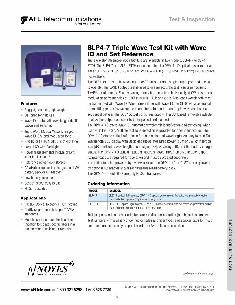
T e s t & I n s p e c t i o n
63
© 2006, AFL Telecommunications, all rights reserved. SLP4-07-2000 Revision 1A, 5.05.06Specifications are subject to change without notice.
Features
• Rugged, handheld, lightweight• Designed for field use• Wave ID - automatic wavelength identifi-
cation and switching
• Triple Wave ID, dual Wave ID, single Wave ID, CW, and modulated Tone
• 270 Hz, 330 Hz, 1 kHz, and 2 kHz Tone• Large LCD with Backlight• Power measurements in dBm or µW;
insertion loss in dB• Reference power level storage• AA alkaline, optional rechargeable NiMH
battery pack or AC adapter• Low battery indicator• Cost-effective, easy to use• N.I.S.T traceable
SLP4-7 Triple Wave Test Kit with Wave ID and Set Reference Triple wavelength single-mode test kits are available in two models, SLP4-7 or SLP4-FTTH. The SLP4-7 and SLP4-FTTH model combine the OPM 4-4D optical power meter and either OLS7-3 (1310/1550/1625 nm) or OLS7-FTTH (1310/1490/1550 nm) LASER source respectively.The OLS7 features triple wavelength LASER output from a single output port and is easy to operate. The LASER output is stabilized to ensure accurate test results per current TIA/EIA requirements. Each wavelength may be transmitted individually at CW or with tone modulation at frequencies of 270Hz, 330Hz, 1kHz and 2kHz. Also, each wavelength may be transmitted with Wave ID. When transmitting with Wave ID, the OLS7 will also support transmitting pairs of wavelengths in an alternating pattern and triple wavelengths in a sequential pattern. The OLS7 output port is equipped with a UCI based removable adapter to allow the output connector to be inspected and cleaned.The OPM 4-4D offers Wave ID, automatic wavelength identification and switching, when used with the OLS7. Multiple test Tone detection is provided for fiber identification. The OPM 4-4D stores optical references for each calibrated wavelength. An easy to read Dual Wavelength LCD display with Backlight shows measured power [dBm or µW] or insertion loss [dB], calibrated wavelengths, tone signal [Hz], wavelength ID, and the battery charge status. The OPM 4-4D optical input port accepts Noyes thread-on style adapter caps. Adapter caps are required for operation and must be ordered separately.In addition to being powered by two AA alkaline, the OPM 4-4D or OLS7 can be powered by optional AC adapter and/or rechargeable NiMH battery pack. The OPM 4-4D and OLS7 are fully N.I.S.T. traceable.
continued on the next page
Ordering Information
MODEL INCLUDES
SLP4-7 OLS7-3 optical light source, OPM 4-4D optical power meter, AA batteries, protective rubber boots, adapter cap, user's guide, and carry case.
SLP4-FTTH OLS7-FTTH optical light source, OPM 4-4D optical power meter, AA batteries, protective rubber boots, adapter cap, user's guide, and carry case.
Test jumpers and connector adapters are required for operation (purchased separately). Test jumpers with a variety of connector styles and fiber types and adapter caps for most common connectors may be purchased from AFL Telecommunications.
Applications
• Passive Optical Networks (PON) testing• Certify single-mode links per TIA/EIA
standards• Modulation Tone mode for fiber iden-
tification to isolate specific fibers in a bundle prior to splicing or rerouting
PA
SS
IVE
IN
FR
AS
TR
UC
TU
RE
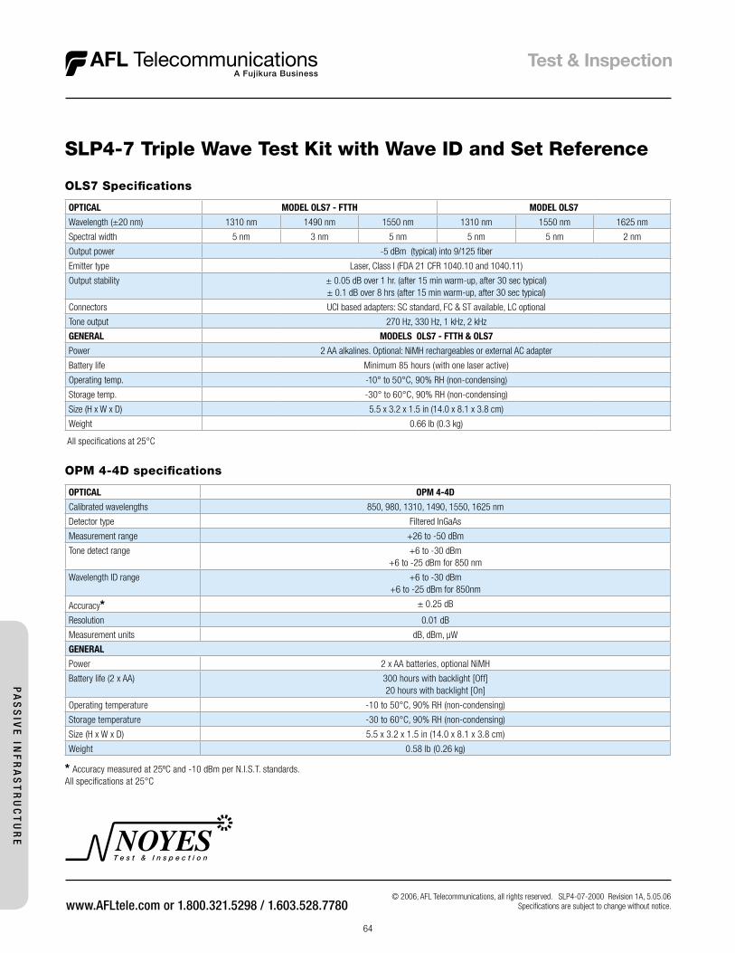
T e s t & I n s p e c t i o n
64
© 2006, AFL Telecommunications, all rights reserved. SLP4-07-2000 Revision 1A, 5.05.06Specifications are subject to change without notice.
SLP4-7 Triple Wave Test Kit with Wave ID and Set Reference
OPM 4-4D specifications
OPTICAL OPM 4-4D
Calibrated wavelengths 850, 980, 1310, 1490, 1550, 1625 nm
Detector type Filtered InGaAs
Measurement range +26 to -50 dBm
Tone detect range +6 to -30 dBm+6 to -25 dBm for 850 nm
Wavelength ID range +6 to -30 dBm+6 to -25 dBm for 850nm
Accuracy* ± 0.25 dB
Resolution 0.01 dB
Measurement units dB, dBm, µW
GENERAL
Power 2 x AA batteries, optional NiMH
Battery life (2 x AA) 300 hours with backlight [Off]20 hours with backlight [On]
Operating temperature -10 to 50°C, 90% RH (non-condensing)
Storage temperature -30 to 60°C, 90% RH (non-condensing)
Size (H x W x D) 5.5 x 3.2 x 1.5 in (14.0 x 8.1 x 3.8 cm)
Weight 0.58 lb (0.26 kg)
* Accuracy measured at 25ºC and -10 dBm per N.I.S.T. standards.All specifications at 25°C
OLS7 Specifications
OPTICAL MODEL OLS7 - FTTH MODEL OLS7
Wavelength (±20 nm) 1310 nm 1490 nm 1550 nm 1310 nm 1550 nm 1625 nm
Spectral width 5 nm 3 nm 5 nm 5 nm 5 nm 2 nm
Output power -5 dBm (typical) into 9/125 fiber
Emitter type Laser, Class I (FDA 21 CFR 1040.10 and 1040.11)
Output stability ± 0.05 dB over 1 hr. (after 15 min warm-up, after 30 sec typical) ± 0.1 dB over 8 hrs (after 15 min warm-up, after 30 sec typical)
Connectors UCI based adapters: SC standard, FC & ST available, LC optional
Tone output 270 Hz, 330 Hz, 1 kHz, 2 kHz
GENERAL MODELS OLS7 - FTTH & OLS7
Power 2 AA alkalines. Optional: NiMH rechargeables or external AC adapter
Battery life Minimum 85 hours (with one laser active)
Operating temp. -10° to 50°C, 90% RH (non-condensing)
Storage temp. -30° to 60°C, 90% RH (non-condensing)
Size (H x W x D) 5.5 x 3.2 x 1.5 in (14.0 x 8.1 x 3.8 cm)
Weight 0.66 lb (0.3 kg)
All specifications at 25°C
PA
SS
IVE
INF
RA
ST
RU
CT
UR
E
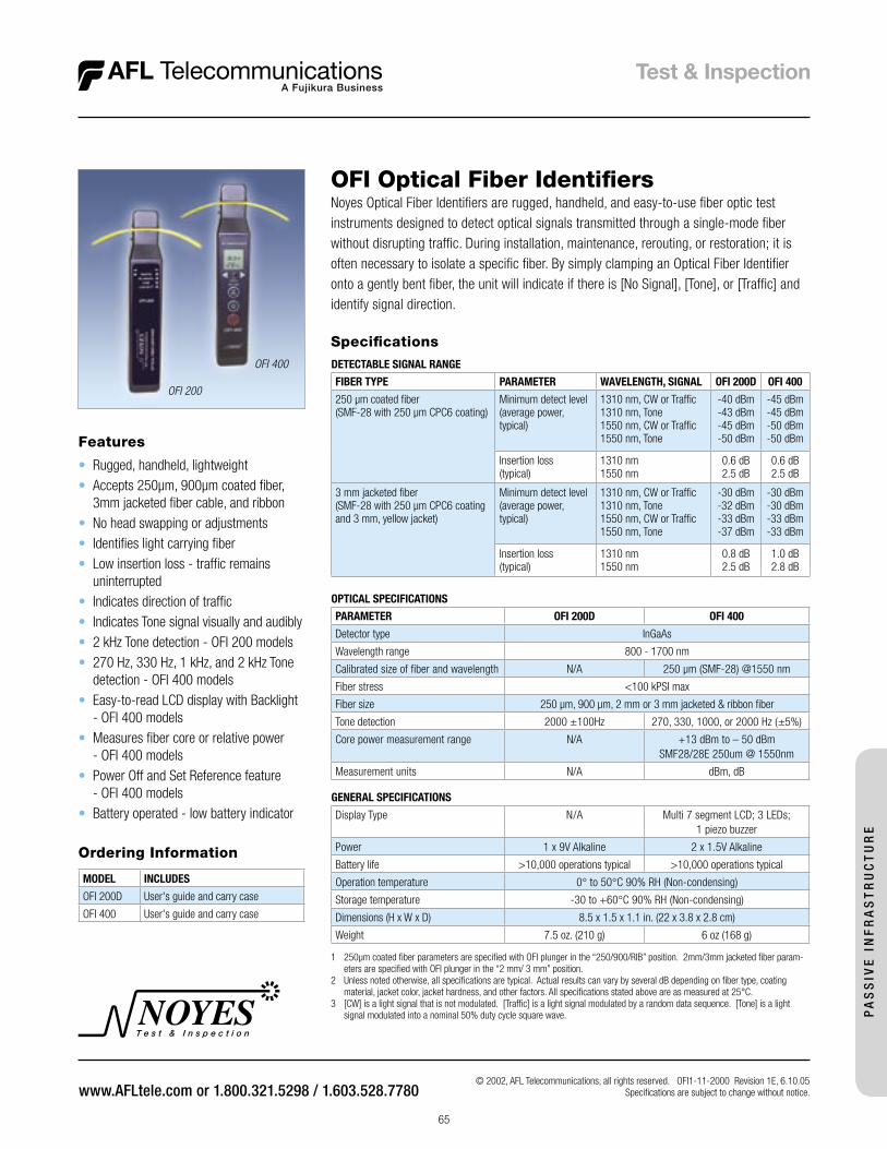
T e s t & I n s p e c t i o n
65
© 2002, AFL Telecommunications, all rights reserved. OFI1-11-2000 Revision 1E, 6.10.05Specifications are subject to change without notice.
Features
• Rugged, handheld, lightweight• Accepts 250µm, 900µm coated fiber,
3mm jacketed fiber cable, and ribbon• No head swapping or adjustments• Identifies light carrying fiber• Low insertion loss - traffic remains
uninterrupted• Indicates direction of traffic• Indicates Tone signal visually and audibly• 2 kHz Tone detection - OFI 200 models• 270 Hz, 330 Hz, 1 kHz, and 2 kHz Tone
detection - OFI 400 models• Easy-to-read LCD display with Backlight
- OFI 400 models• Measures fiber core or relative power
- OFI 400 models• Power Off and Set Reference feature
- OFI 400 models• Battery operated - low battery indicator
OFI Optical Fiber IdentifiersNoyes Optical Fiber Identifiers are rugged, handheld, and easy-to-use fiber optic test instruments designed to detect optical signals transmitted through a single-mode fiber without disrupting traffic. During installation, maintenance, rerouting, or restoration; it is often necessary to isolate a specific fiber. By simply clamping an Optical Fiber Identifier onto a gently bent fiber, the unit will indicate if there is [No Signal], [Tone], or [Traffic] and identify signal direction.
OFI 200
OFI 400
PA
SS
IVE
IN
FR
AS
TR
UC
TU
RE
1 250µm coated fiber parameters are specified with OFI plunger in the “250/900/RIB” position. 2mm/3mm jacketed fiber param-eters are specified with OFI plunger in the “2 mm/ 3 mm” position.
2 Unless noted otherwise, all specifications are typical. Actual results can vary by several dB depending on fiber type, coating material, jacket color, jacket hardness, and other factors. All specifications stated above are as measured at 25°C.
3 [CW] is a light signal that is not modulated. [Traffic] is a light signal modulated by a random data sequence. [Tone] is a light signal modulated into a nominal 50% duty cycle square wave.
Specifications
DETECTABLE SIGNAL RANGE
FIBER TYPE PARAMETER WAVELENGTH, SIGNAL OFI 200D OFI 400
250 µm coated fiber(SMF-28 with 250 µm CPC6 coating)
Minimum detect level (average power, typical)
1310 nm, CW or Traffic1310 nm, Tone1550 nm, CW or Traffic1550 nm, Tone
-40 dBm-43 dBm-45 dBm-50 dBm
-45 dBm-45 dBm-50 dBm-50 dBm
Insertion loss(typical)
1310 nm1550 nm
0.6 dB2.5 dB
0.6 dB2.5 dB
3 mm jacketed fiber (SMF-28 with 250 µm CPC6 coating and 3 mm, yellow jacket)
Minimum detect level (average power, typical)
1310 nm, CW or Traffic1310 nm, Tone1550 nm, CW or Traffic1550 nm, Tone
-30 dBm-32 dBm-33 dBm-37 dBm
-30 dBm-30 dBm-33 dBm-33 dBm
Insertion loss(typical)
1310 nm1550 nm
0.8 dB2.5 dB
1.0 dB2.8 dB
OPTICAL SPECIFICATIONS
PARAMETER OFI 200D OFI 400
Detector type InGaAs
Wavelength range 800 - 1700 nm
Calibrated size of fiber and wavelength N/A 250 µm (SMF-28) @1550 nm
Fiber stress <100 kPSI max
Fiber size 250 µm, 900 µm, 2 mm or 3 mm jacketed & ribbon fiber
Tone detection 2000 ±100Hz 270, 330, 1000, or 2000 Hz (±5%)
Core power measurement range N/A +13 dBm to – 50 dBm SMF28/28E 250um @ 1550nm
Measurement units N/A dBm, dB
Ordering Information
MODEL INCLUDES
OFI 200D User's guide and carry case
OFI 400 User's guide and carry case
GENERAL SPECIFICATIONS
Display Type N/A Multi 7 segment LCD; 3 LEDs; 1 piezo buzzer
Power 1 x 9V Alkaline 2 x 1.5V Alkaline
Battery life >10,000 operations typical >10,000 operations typical
Operation temperature 0° to 50°C 90% RH (Non-condensing)
Storage temperature -30 to +60°C 90% RH (Non-condensing)
Dimensions (H x W x D) 8.5 x 1.5 x 1.1 in. (22 x 3.8 x 2.8 cm)
Weight 7.5 oz. (210 g) 6 oz (168 g)
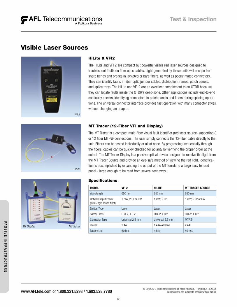
T e s t & I n s p e c t i o n
66
© 2004, AFL Telecommunications, all rights reserved. Revision 2, 5.23.06 Specifications are subject to change without notice.
VFI 2
HiLite
MT TracerMT Display
MT Tracer (12-Fiber VFI and Display)
The MT Tracer is a compact multi-fiber visual fault identifier (red laser source) supporting 8 or 12 fiber MTP® connections. The user simply connects the 12-fiber cable directly to the unit. Fibers can be tested individually or all at once. By progressing sequentially through the fibers, cables can be quickly checked for polarity by verifying the proper order at the output. The MT Tracer Display is a passive optical device designed to receive the light from the MT Tracer Source and provide an eye-safe method of viewing the red light. Identifica-tion is accomplished by expanding the output of the MT ferrule to a large easy to read panel - large enough to be read from several feet away.
HiLite & VFI2
The HiLite and VFI 2 are compact but powerful visible red laser sources designed to troubleshoot faults on fiber optic cables. Light generated by these units will escape from sharp bends and breaks in jacketed or bare fibers, as well as poorly mated connectors. They can identify faults in fiber optic jumper cables, distribution frames, patch panels, and splice trays. The HiLite and VFI 2 are an excellent complement to an OTDR because they can locate faults inside the OTDR’s dead-zone. Other applications include end-to-end continuity checks, identifying connectors in patch panels and fibers during splicing opera-tions. The universal connector interface provides fast operation with many connector styles without changing an adapter.
Visible Laser Sources
Specifications
MODEL VFI 2 HILITE MT TRACER SOURCE
Wavelength 650 nm 650 nm 650 nm
Optical Output Power (into Single-mode fiber)
1 mW, 2 Hz or CW 1 mW, 2 Hz 1 mW, 2 Hz or CW
Emitter Type Laser Laser Laser
Safety Class FDA 2, IEC 2 FDA 2, IEC 2 FDA 2, IEC 2
Connector Type Universal 2.5 mm Universal 2.5 mm MTP®
Power 2 AA 1 AAA Alkaline 2 AA
Battery Life 60 hrs. 4 hrs. 40 hrs.P
AS
SIV
E IN
FR
AS
TR
UC
TU
RE
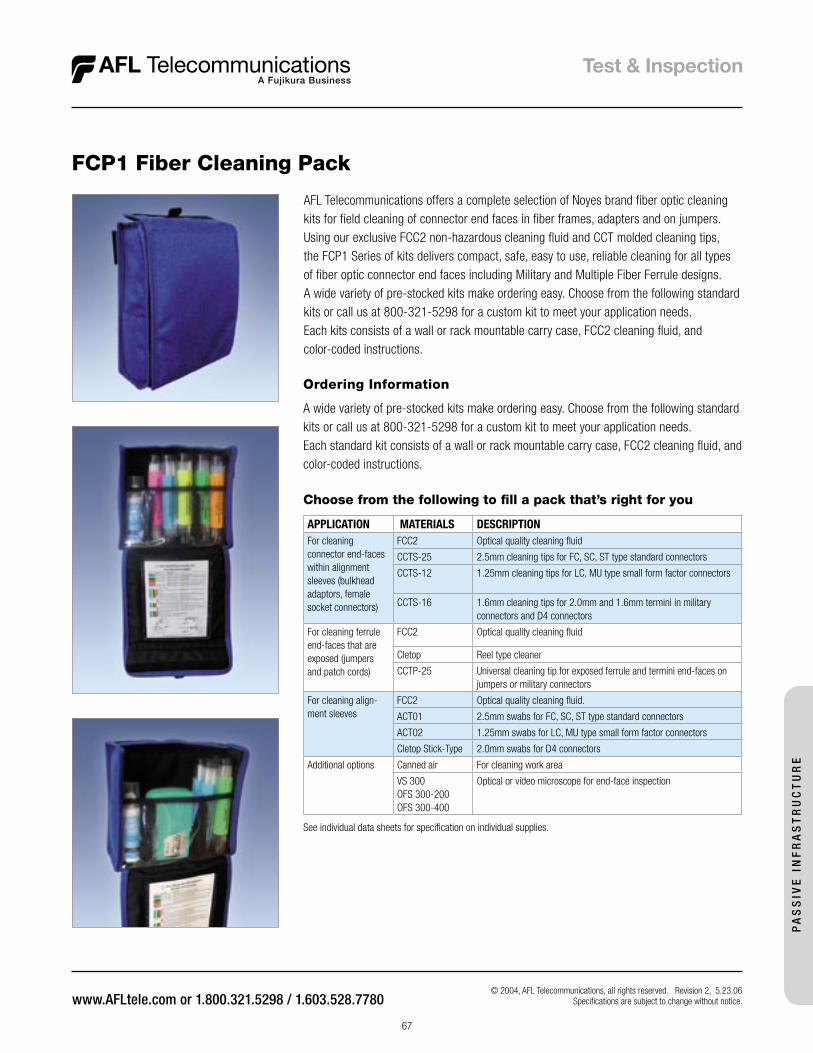
T e s t & I n s p e c t i o n
67
© 2004, AFL Telecommunications, all rights reserved. Revision 2, 5.23.06 Specifications are subject to change without notice.
AFL Telecommunications offers a complete selection of Noyes brand fiber optic cleaning kits for field cleaning of connector end faces in fiber frames, adapters and on jumpers. Using our exclusive FCC2 non-hazardous cleaning fluid and CCT molded cleaning tips, the FCP1 Series of kits delivers compact, safe, easy to use, reliable cleaning for all types of fiber optic connector end faces including Military and Multiple Fiber Ferrule designs.A wide variety of pre-stocked kits make ordering easy. Choose from the following standard kits or call us at 800-321-5298 for a custom kit to meet your application needs. Each kits consists of a wall or rack mountable carry case, FCC2 cleaning fluid, and color-coded instructions.
FCP1 Fiber Cleaning Pack
Choose from the following to fill a pack that’s right for you
APPLICATION MATERIALS DESCRIPTION For cleaning connector end-faces within alignment sleeves (bulkhead adaptors, female socket connectors)
FCC2 Optical quality cleaning fluid
CCTS-25 2.5mm cleaning tips for FC, SC, ST type standard connectors
CCTS-12 1.25mm cleaning tips for LC, MU type small form factor connectors
CCTS-16 1.6mm cleaning tips for 2.0mm and 1.6mm termini in military connectors and D4 connectors
For cleaning ferrule end-faces that are exposed (jumpers and patch cords)
FCC2 Optical quality cleaning fluid
Cletop Reel type cleaner
CCTP-25 Universal cleaning tip for exposed ferrule and termini end-faces on jumpers or military connectors
For cleaning align-ment sleeves
FCC2 Optical quality cleaning fluid.
ACT01 2.5mm swabs for FC, SC, ST type standard connectors
ACT02 1.25mm swabs for LC, MU type small form factor connectors
Cletop Stick-Type 2.0mm swabs for D4 connectors
Additional options Canned air For cleaning work area
VS 300OFS 300-200OFS 300-400
Optical or video microscope for end-face inspection
See individual data sheets for specification on individual supplies.
Ordering Information
A wide variety of pre-stocked kits make ordering easy. Choose from the following standard kits or call us at 800-321-5298 for a custom kit to meet your application needs.Each standard kit consists of a wall or rack mountable carry case, FCC2 cleaning fluid, and color-coded instructions.
PA
SS
IVE
IN
FR
AS
TR
UC
TU
RE
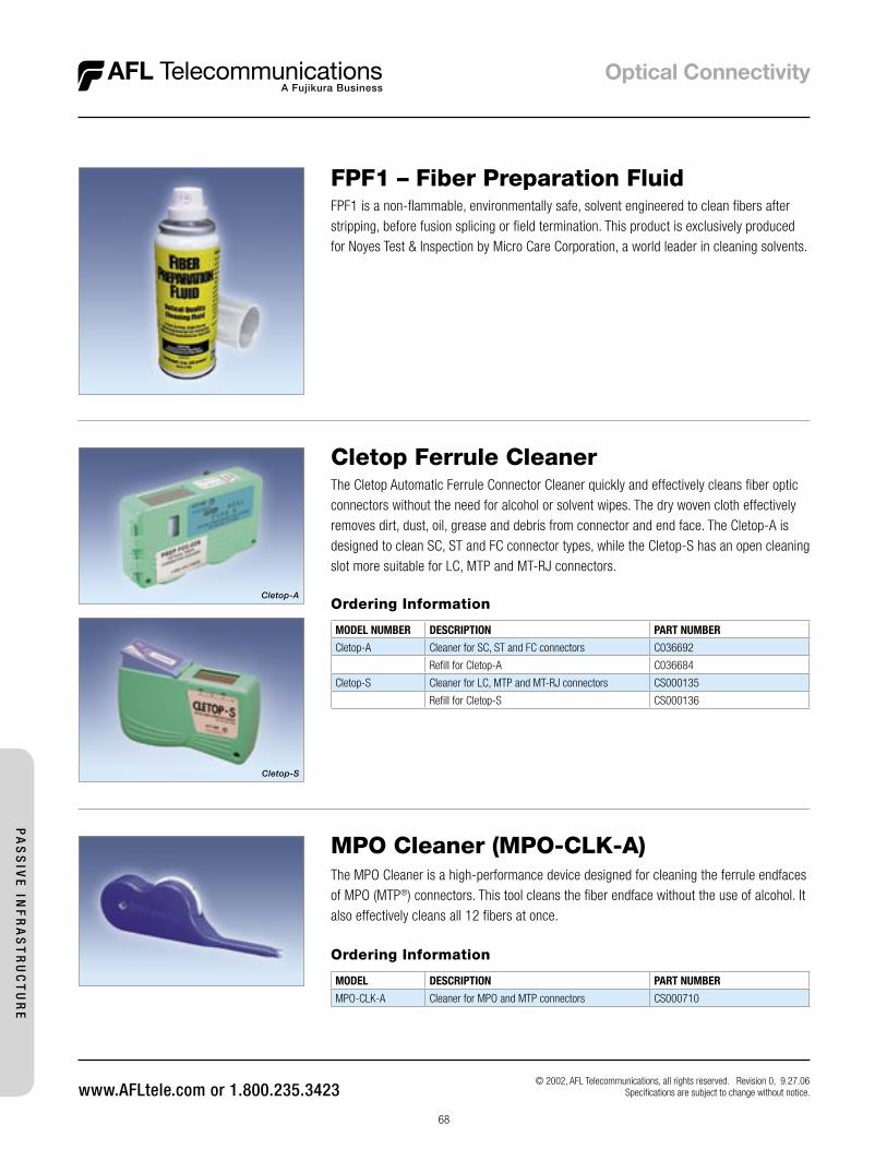
68
Cletop Ferrule CleanerThe Cletop Automatic Ferrule Connector Cleaner quickly and effectively cleans fiber optic connectors without the need for alcohol or solvent wipes. The dry woven cloth effectively removes dirt, dust, oil, grease and debris from connector and end face. The Cletop-A is designed to clean SC, ST and FC connector types, while the Cletop-S has an open cleaning slot more suitable for LC, MTP and MT-RJ connectors.
Ordering Information
MODEL NUMBER DESCRIPTION PART NUMBER
Cletop-A Cleaner for SC, ST and FC connectors C036692
Refill for Cletop-A C036684
Cletop-S Cleaner for LC, MTP and MT-RJ connectors CS000135
Refill for Cletop-S CS000136
Cletop-A
Cletop-S
© 2002, AFL Telecommunications, all rights reserved. Revision 0, 9.27.06 Specifications are subject to change without notice.
MPO Cleaner (MPO-CLK-A)The MPO Cleaner is a high-performance device designed for cleaning the ferrule endfaces of MPO (MTP®) connectors. This tool cleans the fiber endface without the use of alcohol. It also effectively cleans all 12 fibers at once.
Ordering Information
MODEL DESCRIPTION PART NUMBER
MPO-CLK-A Cleaner for MPO and MTP connectors CS000710
PA
SS
IVE
INF
RA
ST
RU
CT
UR
E
FPF1 – Fiber Preparation FluidFPF1 is a non-flammable, environmentally safe, solvent engineered to clean fibers after stripping, before fusion splicing or field termination. This product is exclusively produced for Noyes Test & Inspection by Micro Care Corporation, a world leader in cleaning solvents.