ACCESS MANAGEMENT GUIDELINES - London, Ontario · PDF fileApril 2012 Page i. ACKNOWLEDGEMENTS...
43
City of London ACCESS MANAGEMENT GUIDELINES 2015
Transcript of ACCESS MANAGEMENT GUIDELINES - London, Ontario · PDF fileApril 2012 Page i. ACKNOWLEDGEMENTS...

City of London
ACCESS MANAGEMENT GUIDELINES
2015
April 2012 Page i.
ACKNOWLEDGEMENTS
The Access Management Guidelines were originally prepared by IBI Group in 2007. Dillon Consulting Limited then prepared the City of London’s Access Management Policy in March 2009, which included the Access Control By-law and updated the Access Management Guidelines accordingly. Since then, additional modifications have been incorporated by City staff. These guidelines are the summation of contributions made by all parties. The City of London gratefully acknowledges IBI Group and Dillon Consulting Limited for their assistance and technical input provided.
DISCLAIMER
The Access Management Guidelines is not intended to be used as a basis for establishing civil liability. The material presented in this text was carefully researched and presented based on an industry scan of other jurisdictions and governing bodies. However, no warranty expressed or implied is made on the accuracy of the contents or their extraction from reference to publications.
TABLE OF CONTENTS
April 2012 Page ii.
INTRODUCTION ................................................................................................................................. 1
1. ACCESS LAYOUT ................................................................................................................... 3
1.1. Road Classification System ................................................................................................................. 3
1.2. Subdivision Road Network ................................................................................................................... 4
1.3. Number of Accesses ............................................................................................................................. 5
1.4. Access Connection Spacing ................................................................................................................ 5
1.4 .1 Signal i zed In tersec t ions / Dr iveways . . . . . . . . . . . . . . . . . . . . . . . . . . . . . . . . . . . . . . . . . . . . . . . . . . . . . . . . . . . . 5
1.4 .2 Major Access Connect ions . . . . . . . . . . . . . . . . . . . . . . . . . . . . . . . . . . . . . . . . . . . . . . . . . . . . . . . . . . . . . . . . . . . . . . . . . . . 6
1.4 .3 Minor Access Connect ions . . . . . . . . . . . . . . . . . . . . . . . . . . . . . . . . . . . . . . . . . . . . . . . . . . . . . . . . . . . . . . . . . . . . . . . . . . . 7
1.4.3.1 At Stop Controlled Intersection ................................................................................................... 7
1.4.3.2 At Signal Controlled Intersection ................................................................................................. 8
1.4.3.3 Minimum Driveway Separation Distance .................................................................................... 8
1.5. Interchange Access Offset Spacing .................................................................................................... 9
1.6. Capacity and Level-of-Service ........................................................................................................... 11
1.7. Alignment of Opposing Accesses ..................................................................................................... 11
1.8. Angle of Access Centreline ................................................................................................................ 13
1.9. Site Inter-Connection .......................................................................................................................... 13
1.10. Joint Access / Common Internal Driveways ..................................................................................... 13
1.11. Grade .................................................................................................................................................... 15
1.12. Sight Line Distance ............................................................................................................................. 16
1.13. Access Widths ..................................................................................................................................... 17
1.14. Radii...................................................................................................................................................... 19
1.15. Curb Radius – No Encroachment ...................................................................................................... 20
1.16. Curb Return Design ............................................................................................................................ 20
2. ACCESS TURNING RESTRICTIONS .................................................................................... 22
2.1. Operating Requirements..................................................................................................................... 22
TABLE OF CONTENTS
April 2012 Page iii.
2.2. Inbound Left-Turn Restriction ............................................................................................................ 23
2.3. Left-Turn Egress Restriction .............................................................................................................. 23
2.4. Rights-In / Rights-Out ......................................................................................................................... 24
2.5. Rights-In / Rights-Out “Pork Chop” ................................................................................................... 24
3. ROADWAY FEATURES......................................................................................................... 25
3.1. Left Turn Lane ..................................................................................................................................... 25
3.1 .1 Volume Warrant . . . . . . . . . . . . . . . . . . . . . . . . . . . . . . . . . . . . . . . . . . . . . . . . . . . . . . . . . . . . . . . . . . . . . . . . . . . . . . . . . . . . . . . . . . 25
3.1 .2 Col l is ion Warrant . . . . . . . . . . . . . . . . . . . . . . . . . . . . . . . . . . . . . . . . . . . . . . . . . . . . . . . . . . . . . . . . . . . . . . . . . . . . . . . . . . . . . . . . 25
3.2. Right-Turn Lane ................................................................................................................................... 25
3.3. Medians ................................................................................................................................................ 26
3.4. Signal Warrant ..................................................................................................................................... 26
3.5. Bus Bays .............................................................................................................................................. 26
3.5 .1 St ructure . . . . . . . . . . . . . . . . . . . . . . . . . . . . . . . . . . . . . . . . . . . . . . . . . . . . . . . . . . . . . . . . . . . . . . . . . . . . . . . . . . . . . . . . . . . . . . . . . . . . 26
3.5 .2 Geomet ry . . . . . . . . . . . . . . . . . . . . . . . . . . . . . . . . . . . . . . . . . . . . . . . . . . . . . . . . . . . . . . . . . . . . . . . . . . . . . . . . . . . . . . . . . . . . . . . . . . . . 27
3.6. Sidewalks ............................................................................................................................................. 27
3.6 .1 Locat ion . . . . . . . . . . . . . . . . . . . . . . . . . . . . . . . . . . . . . . . . . . . . . . . . . . . . . . . . . . . . . . . . . . . . . . . . . . . . . . . . . . . . . . . . . . . . . . . . . . . . . 27
3.6 .2 Geomet ry . . . . . . . . . . . . . . . . . . . . . . . . . . . . . . . . . . . . . . . . . . . . . . . . . . . . . . . . . . . . . . . . . . . . . . . . . . . . . . . . . . . . . . . . . . . . . . . . . . . . 27
3.7. Bicycle Paths ....................................................................................................................................... 28
4. PARKING OPERATIONS....................................................................................................... 29
4.1. Clear Throat Distance ......................................................................................................................... 29
4.2. Lay-Bys ................................................................................................................................................ 30
4.3. Turnaround Areas ............................................................................................................................... 31
4.4. Drive-Throughs .................................................................................................................................... 32
4.5. Loading Docks ..................................................................................................................................... 32
4.6. End Island Treatments ........................................................................................................................ 33
April 2012 Page iv
LIST OF EXHIBITS
Exhibit 1-1: Road Classification System ............................................................................................ 3 Exhibit 1-2: Subdivision Road Network .............................................................................................. 4 Exhibit 1-3: Corner Clearance ............................................................................................................ 7 Exhibit 1-4: Arterial Minimum Driveway Spacing ............................................................................... 9 Exhibit 1-5: Minimum Spacing for a Parclo A-4 Interchange ............................................................ 10 Exhibit 1-6: Centreline Alignment ..................................................................................................... 11 Exhibit 1-7: Spacing considerations for opposing driveways ........................................................... 12 Exhibit 1-8: Angle of Intersection ..................................................................................................... 13 Exhibit 1-9: Joint Access .................................................................................................................. 15 Exhibit 1-10: Plan View of an At-Grade Landing.............................................................................. 15 Exhibit 1-11: Profile View of an At-Grade Landing........................................................................... 16 Exhibit 1-12: Driveway Layouts ........................................................................................................ 18 Exhibit 1-13: Radii ............................................................................................................................ 20 Exhibit 1-14: Curb Radius – No Encroachment ............................................................................... 20 Exhibit 1-15: Curb Return Design .................................................................................................... 21 Exhibit 2-1: Inbound Left Turn Restriction to Driveways .................................................................. 23 Exhibit 2-2: Left Turn Egress Restriction from Driveway ................................................................. 23 Exhibit 2-3: Both Left Turns Restricted ............................................................................................ 24 Exhibit 2-4: Both Left Turns Restricted ........................................................................................... 24 Exhibit 4-1: Minimum Distance to a Parking Space ......................................................................... 30 Exhibit 4-2: Minimum Distance to a Parking Aisle ........................................................................... 30 Exhibit 4-3: Lay-by and Passenger Drop-off Zone ........................................................................... 31 Exhibit 4-4: Turnaround Area for Passenger Vehicle....................................................................... 32 Exhibit 4-5: Loading and Courier Areas ............................................................................................ 33
LIST OF TABLES
Table 1-1: Spacing Between Signalized Intersections / Driveways .................................................... 6 Table 1-2: Spacing from Signalized Intersections............................................................................... 6 Table 1-3: Minimum Spacing between Major Access Connections .................................................... 6 Table 1-4: Minimum Spacing for Highway Interchange with Two-Lane Crossing Road ................... 10 Table 1-5: Driveway Grades and Grade Changes ............................................................................ 16 Table 1-6: Driveway Dimensions ...................................................................................................... 19 Table 3-1: Geometry of a London Transit Bus Bay........................................................................... 27 Table 4-1: Clear Throat Distances – Parking Facilities ..................................................................... 29
LIST OF APPENDICES
Appendix A: Turning Template Appendix B: End Island Treatments
City of London
ACCESS MANAGEMENT GUIDELINES
April 2012 Page 1
INTRODUCTION
This document recommends guidelines for Access Management in the City of London. The purpose of
the guidelines are to provide a framework for access control that will maintain a high level of service for
through-traffic, while providing reasonable access to abutting properties. The overall goals of the
guideline are to reduce collisions, alleviate traffic congestion, reduce energy consumption, preserve
the long term integrity of the traffic movement function, and promote an aesthetically pleasing arterial
corridor. These guidelines are intended to manage the provision of access to the public road system
for new development or redevelopment, and proactively through corridor reconstruction. The
recommended guidelines are based on an industry scan of other jurisdictions and governing bodies.
In this document, the words “shall”, “should” and “may” are used to describe specific conditions
concerning these guidelines. To clarify the meaning intended in this document by these words, the
following definitions shall apply:
1. SHALL or MUST - a mandatory condition. This falls under the categories of “Legal
Requirement(s), or “Interpretation”. Where certain requirements in the design or application of
the device are described with the “shall” stipulation, it is mandatory when an installation is made
that these requirements be met.
2. SHOULD - an advisory condition. This falls under the category of “Recommended Practice”.
Where the word “should” is used, it is considered to be advisable usage, recommended but not
mandatory.
3. MAY - a permissive condition. This falls under the category of “Guideline”. No requirement for
design or application is intended.
List of Guidelines
The following lists the guidelines that are addressed in this document:
Access Layout;
Turning restrictions;
Roadway features; and
Parking operations.
Documentation Scan
The following documents were reviewed in performing the industry scan:
Ontario Highway Traffic Act Regulations;
Manual of Uniform Traffic Control Devices for Canada TAC, 4th Edition;
Manual on Uniform Traffic Control Devices, FHWA;
Institute of Transportation Engineers (ITE) Traffic Engineering Handbook, 5th Edition;
April 2012 Page 2
ITE Transportation and Land Development, 2nd Edition.
Jurisdiction Scan
Region of Durham;
Region of Halton;
City of Toronto;
City of Calgary;
City of Edmonton;
City of Regina;
City of Saskatoon.
Reference Documents
The following is a list of reference documents that should be consulted in conjunction with these
guidelines:
City of London Documents:
Site Plan Control Area By-law;
Subdivision and Development Manual;
Transportation Design Specifications;
The Official Plan;
Transportation Impact Study Guidelines.
External Documents:
TAC – Geometric Design Guide for Canadian Roads.
April 2012 Page 3
1. ACCESS LAYOUT
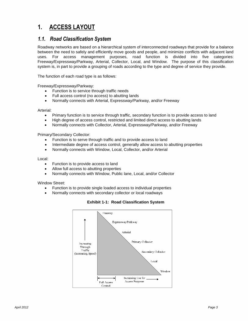
1.1. Road Classification System
Roadway networks are based on a hierarchical system of interconnected roadways that provide for a balance
between the need to safely and efficiently move goods and people, and minimize conflicts with adjacent land
uses. For access management purposes, road function is divided into five categories:
Freeway/Expressway/Parkway, Arterial, Collector, Local, and Window. The purpose of this classification
system is, in part to provide a grouping of roads according to the type and degree of service they provide.
The function of each road type is as follows:
Freeway/Expressway/Parkway:
Function is to service through traffic needs
Full access control (no access) to abutting lands
Normally connects with Arterial, Expressway/Parkway, and/or Freeway
Arterial:
Primary function is to service through traffic, secondary function is to provide access to land
High degree of access control, restricted and limited direct access to abutting lands
Normally connects with Collector, Arterial, Expressway/Parkway, and/or Freeway
Primary/Secondary Collector:
Function is to serve through traffic and to provide access to land
Intermediate degree of access control, generally allow access to abutting properties
Normally connects with Window, Local, Collector, and/or Arterial
Local:
Function is to provide access to land
Allow full access to abutting properties
Normally connects with Window, Public lane, Local, and/or Collector
Window Street:
Function is to provide single loaded access to individual properties
Normally connects with secondary collector or local roadways
Exhibit 1-1: Road Classification System

April 2012 Page 4
1.2. Subdivision Road Network
A Plan of Subdivision usually entails the redevelopment of a substantial parcel of land such that a local road
network is required to service the lands. The development of a local road network is encouraged so that
traffic activities are organized at specific access points.
Practice
Direct access to a new parcel of land must be obtained from a local road network that connects to the arterial
road. Direct access to an arterial road must be minimized, and therefore, all proposed driveways must be
justified. In addition, the standards as set out in the Guidelines also apply to the provision of a new public
road connecting to the arterial road as shown in Exhibit 1-2.
It is important that volumes be very low and the speeds be low on local residential streets. These can be
limited by assigning a maximum length for cul-de-sac* and local streets:
The City suggested maximum for cul-de-sac is 215 metres; Suggested maximums for other local
streets are 395 metres and 50 to 75 dwellings.
* Cul-de-sacs are discouraged and are implemented only when other options are not available.
References
ITE Transportation and Land Development, Chapter 13: Residential Neighbourhood Streets, page 24.
Exhibit 1-2: Subdivision Road Network

April 2012 Page 5
1.3. Number of Accesses
The number of new driveways that will be permitted to a specific site depends on several factors: the density
and type of land use, the classification of the adjacent roadway, the type of operations that will be permitted
at the new driveway(s), and the location and operating activity of existing driveways or local road
connections. The implementation of joint accesses and/or common internal drives is encouraged.
Practice
Direct access to an arterial road must be minimized, and therefore, all proposed driveways must be justified.
The developer must first pursue alternate access arrangements as follows:
Obtain access from the collector or local road network;
Attempt to negotiate joint accesses and/or common internal drive arrangement with adjacent
property owners;
Develop private “commercial service roads” on-site, with adjacent property owners, to manage
traffic circulation needs on-site.
Joint accesses are encouraged and/or may be required to minimize the number of driveways onto arterial
roads. The City may place a 0.3 metres (1foot) reserve along the edge of these road allowances to prevent
the addition of driveways.
The preference of the City is for one driveway per development to an abutting arterial roadway. Where
development is consolidating existing parcels, consolidation and/or removal of existing driveways may be
required. Where development is being undertaken in a phased implementation, temporary driveways may
be permitted until such time that the ultimate access to the development has been made, at which time the
temporary driveway shall be removed. Additional driveway access to the arterial road network will be
subject to special considerations such as traffic analyses justifying the need for additional access to improve
safety, flow and/or circulation and shall meet the spacing requirements set forth in Section 1.4 of this
guideline.
1.4. Access Connection Spacing
There are three types of access connections to City of London roads:
Signalized intersections / signalized driveways
Major access connections (intersections and significant driveways)
Minor access connections (driveways)
All significant driveway access connections shall meet or exceed the connection spacing requirements of the
appropriate road class as specified in Tables 1-1 to 1-3. A significant driveway is defined as a driveway
serving a land use or development block that generates 100 or more vehicles per day during traffic peak
periods.
1.4.1 Signal ized Intersect ions / Driveways
Table 1-1 contains the desirable and minimum allowable spacing for signalized intersections on City of London roadways. Expressways are to be grade separated with freeways, other expressways or arterial roads. At-grade intersections with arterial roads may occur at widely spaced intervals greater than or equal to 800m. For urban divided arterial roadways, the desirable signal spacing may be reduced from 800m to 400m if the subject signal, to the satisfaction of the City Engineer, maintains the capacity and safety of the arterial corridor, or if the signal does not impact signal progression excessively.
April 2012 Page 6
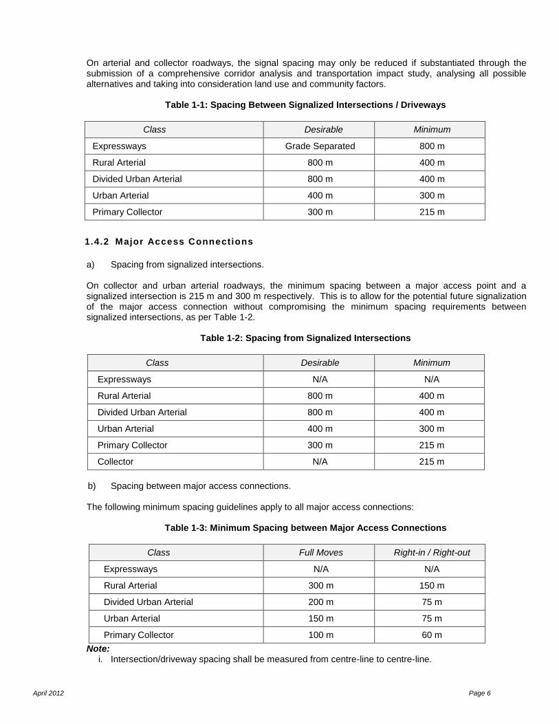
On arterial and collector roadways, the signal spacing may only be reduced if substantiated through the submission of a comprehensive corridor analysis and transportation impact study, analysing all possible alternatives and taking into consideration land use and community factors.
Table 1-1: Spacing Between Signalized Intersections / Driveways
Class Desirable Minimum
Expressways Grade Separated 800 m
Rural Arterial 800 m 400 m
Divided Urban Arterial 800 m 400 m
Urban Arterial 400 m 300 m
Primary Collector 300 m 215 m
1.4.2 Major Access Connections
a) Spacing from signalized intersections. On collector and urban arterial roadways, the minimum spacing between a major access point and a signalized intersection is 215 m and 300 m respectively. This is to allow for the potential future signalization of the major access connection without compromising the minimum spacing requirements between signalized intersections, as per Table 1-2.
Table 1-2: Spacing from Signalized Intersections
Class Desirable Minimum
Expressways N/A N/A
Rural Arterial 800 m 400 m
Divided Urban Arterial 800 m 400 m
Urban Arterial 400 m 300 m
Primary Collector 300 m 215 m
Collector N/A 215 m
b) Spacing between major access connections.
The following minimum spacing guidelines apply to all major access connections:
Table 1-3: Minimum Spacing between Major Access Connections
Class Full Moves Right-in / Right-out
Expressways N/A N/A
Rural Arterial 300 m 150 m
Divided Urban Arterial 200 m 75 m
Urban Arterial 150 m 75 m
Primary Collector 100 m 60 m
Note: i. Intersection/driveway spacing shall be measured from centre-line to centre-line.
April 2012 Page 7
ii. Additional spacing over and above that set forth in Tables 1-1, 1-2, and 1-3 may be required if determined that there is insufficient left turn queue storage or weave manoeuvre area between adjacent intersections. This determination shall be made under peak conditions.
iii. Major access connections are not permitted on Expressway roadways.
Reference
York Region Access Guideline for Regional Roads
1.4.3 Minor Access Connections
1.4.3.1 At Stop Controlled Intersection
Practice
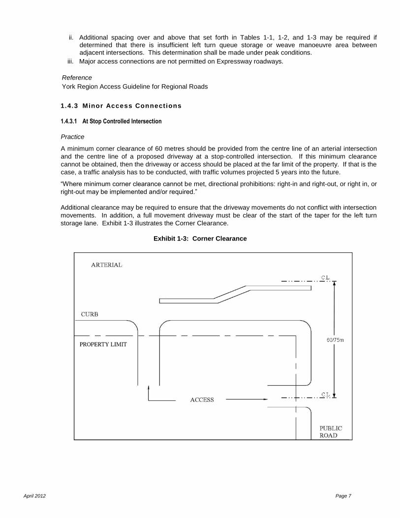
A minimum corner clearance of 60 metres should be provided from the centre line of an arterial intersection
and the centre line of a proposed driveway at a stop-controlled intersection. If this minimum clearance
cannot be obtained, then the driveway or access should be placed at the far limit of the property. If that is the
case, a traffic analysis has to be conducted, with traffic volumes projected 5 years into the future.
“Where minimum corner clearance cannot be met, directional prohibitions: right-in and right-out, or right in, or
right-out may be implemented and/or required.”
Additional clearance may be required to ensure that the driveway movements do not conflict with intersection
movements. In addition, a full movement driveway must be clear of the start of the taper for the left turn
storage lane. Exhibit 1-3 illustrates the Corner Clearance.
Exhibit 1-3: Corner Clearance
April 2012 Page 8
Typically, a further restriction to this practice is made in the case of vehicle service stations (“gas stations”).
Only one driveway is desirable on an arterial road, located at the edge of the property. The permitted
movements are typically limited to right in/right out.
References
Metro Toronto Transportation Access Management Guidelines
Transportation and Land Development, Chapter 6: Access Locations for Site Development, page 6-25.
1.4.3.2 At Signal Controlled Intersection
Practice
A minimum corner clearance of 75 metres should be provided from the centre line of an arterial signalized
intersection and the centre line of a proposed driveway adjacent a traffic signal-controlled intersection. If this
minimum clearance cannot be obtained, then the driveway or access clearance should be placed at the far
limit of the property. Furthermore, a traffic analysis has to be conducted with traffic volumes projected 5
years into the future, to address potential impacts on traffic operations.
“Where minimum corner clearance cannot be met, directional prohibitions: right-in and right-out, or right in, or
right-out may be implemented and/or required.”
Additional clearance may be required to ensure that the driveway movements do not conflict with intersection
movements. In addition, a full movement driveway must be clear of the start of the taper for the left turn
storage lane. Exhibit 1-3 illustrates the Corner Clearance. These guidelines apply to both public roads and
private roads connecting to a signalized intersection.
Typically, an exception to this practice is made in the case of vehicle service stations (“gas stations”). Only
one driveway is desirable on an arterial road, located at the edge of the property. The permitted movements
are typically limited to right in/right out.
References
Metro Toronto Transportation Access Management Guidelines
Transportation and Land Development, Chapter 6: Access Locations for Site Development, page 6-25.
1.4.3.3 Minimum Driveway Separation Distance
The spacing of driveways is related to the number and location of existing adjacent driveways and the
number of new unsignalized intersections (driveways) proposed to serve the subject site. Two key factors
influence minimum spacing requirements: traffic activity to/from the arterial road and the specific design
elements of the proposed driveway. Spacing criteria seek to achieve the following objectives:
Clearly identify which property the driveway is serving;
Minimize the conflict areas between vehicles that enter/exit the proposed driveway, existing
driveways, and the arterial road;
Maintain usable boulevards between driveways for the placement of utilities, traffic control
devices and road amenities.
Practice
Strict applications of traffic engineering criteria may place desirable spacing requirements at 150
metres along an arterial roadway. However, this type of spacing is mostly unacceptable in several
urban and suburban environments. Typically, a spacing of 30 – 60 metres is used along an arterial or
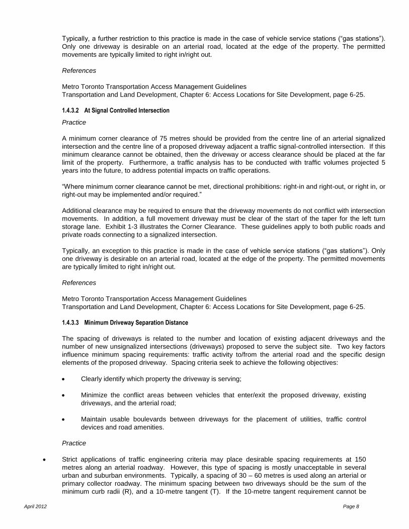
primary collector roadway. The minimum spacing between two driveways should be the sum of the
minimum curb radii (R), and a 10-metre tangent (T). If the 10-metre tangent requirement cannot be
April 2012 Page 9
achieved, provisions for a joint access connection should be considered. The radii are determined by
the type of land use, as outlined in Table 1-6. Exhibit 1-4 illustrates arterial minimum driveway spacing.
Exhibit 1-4: Arterial Minimum Driveway Spacing
References
Traffic Engineering Handbook, Chapter 10, Page 316
Part 2 of the TAC Geometric Design Guide for Canadian Roads (1999), Section 3.2.9.8
Metro Toronto Transportation Access Management Guidelines
1.5. Interchange Access Offset Spacing
Interchanges provide the means of moving traffic between freeways, expressways and crossroads. As a general rule, public road, commercial / private road and private access connections are not to be located within the functional interchange area, unless the location meets the City’s offset spacing criteria as identified in Exhibit 1-5. Access connections are not permitted within a right-turn channelization, auxiliary lane, taper or similar facility at an interchange. It should be noted that under the public transportation and Highway Improvement Act, the Ministry of Transportation has jurisdiction over the provision of all access connections within 400 metres of an intersection with a Provincial Highway. The Functional Interchange Area is the section of crossing road that extends both upstream and downstream from the physical freeway or expressway ramp terminal area itself. The area is controlled to enable a motorist to enter and pass through the ramp terminal intersection before having to consider a potential conflict at a subsequent access connection. Practice – Access Connection Offset Spacing Criteria Adequate spacing and access design for crossroads in the vicinity of interchanges avoids traffic backups onto the mainline and preserves safe and efficient traffic operation. Recommended access spacing adjacent to an interchange is indicated in Table 1-4 and Exhibit 1-5.
April 2012 Page 10
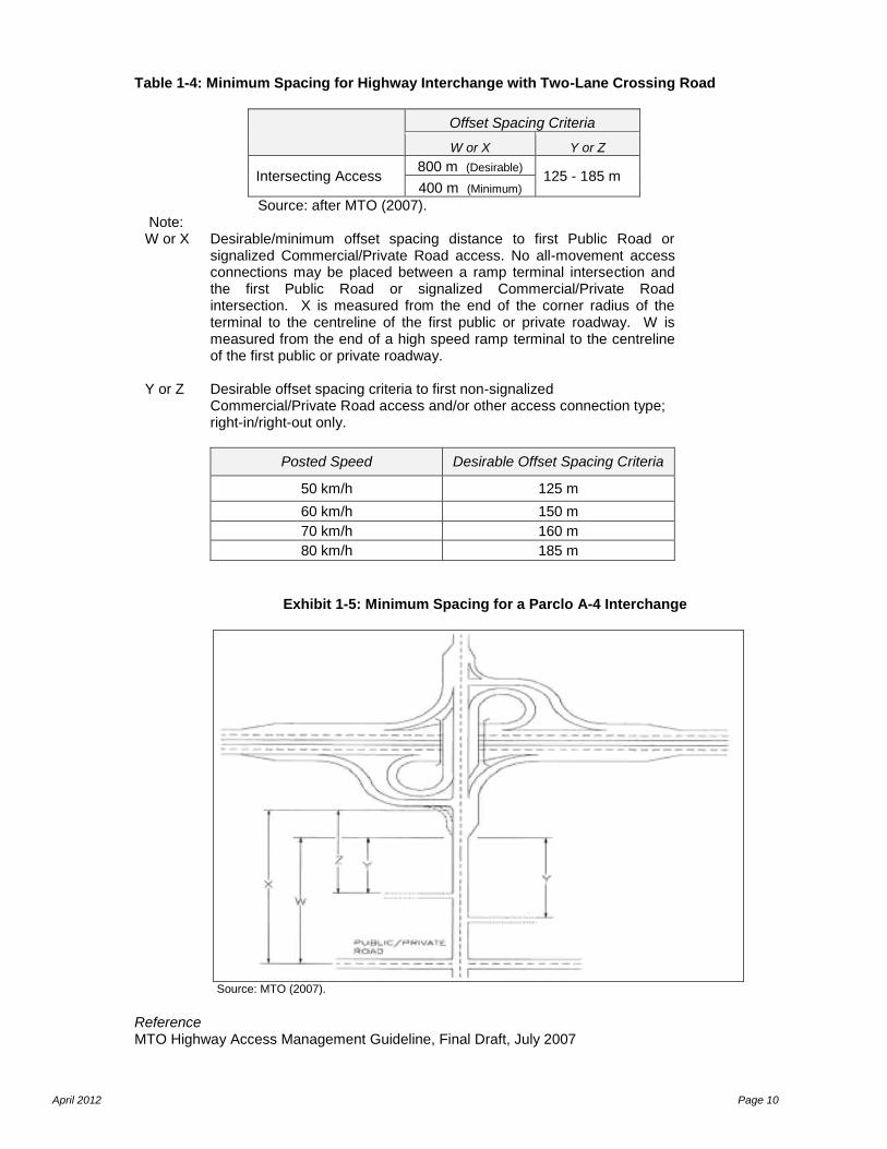
Table 1-4: Minimum Spacing for Highway Interchange with Two-Lane Crossing Road
Offset Spacing Criteria
W or X Y or Z
Intersecting Access 800 m (Desirable)
125 - 185 m 400 m (Minimum)
Source: after MTO (2007). Note: W or X Desirable/minimum offset spacing distance to first Public Road or
signalized Commercial/Private Road access. No all-movement access connections may be placed between a ramp terminal intersection and the first Public Road or signalized Commercial/Private Road intersection. X is measured from the end of the corner radius of the terminal to the centreline of the first public or private roadway. W is measured from the end of a high speed ramp terminal to the centreline of the first public or private roadway.
Y or Z
Desirable offset spacing criteria to first non-signalized Commercial/Private Road access and/or other access connection type; right-in/right-out only.
Posted Speed Desirable Offset Spacing Criteria
50 km/h 125 m
60 km/h 150 m
70 km/h 160 m
80 km/h 185 m
Exhibit 1-5: Minimum Spacing for a Parclo A-4 Interchange
Source: MTO (2007).
Reference MTO Highway Access Management Guideline, Final Draft, July 2007
April 2012 Page 11
1.6. Capacity and Level-of-Service
Any access connection to the arterial road system must offer sufficient capacity for all movements permitted. Left turn movements from the arterial road network must provide sufficient reserve capacity (v/c ratio <0.90) and a good level-of-service (level-of-service D or better). Left turns movement onto the arterial road network must have sufficient capacity (v/c<1.00) and manageable delays and queues. Signalized access points must allow for adequate capacity (v/c <0.90), and favourable road environment conditions. Where an acceptable level-of-service can not be maintained during peak hour conditions, and/or if there is potential to create unacceptable adverse operational and safety impacts on the arterial road network, directional prohibitions, rights-in and right-out, or right-in, or right-out may be implemented and/or required. Other mitigating measures such as roadway or traffic control improvements, joint access and/or common internal drive may also be necessary to facilitate access to the arterial road network. Reference: Regional Municipality of Halton, Access Management Policy for Regional Roads
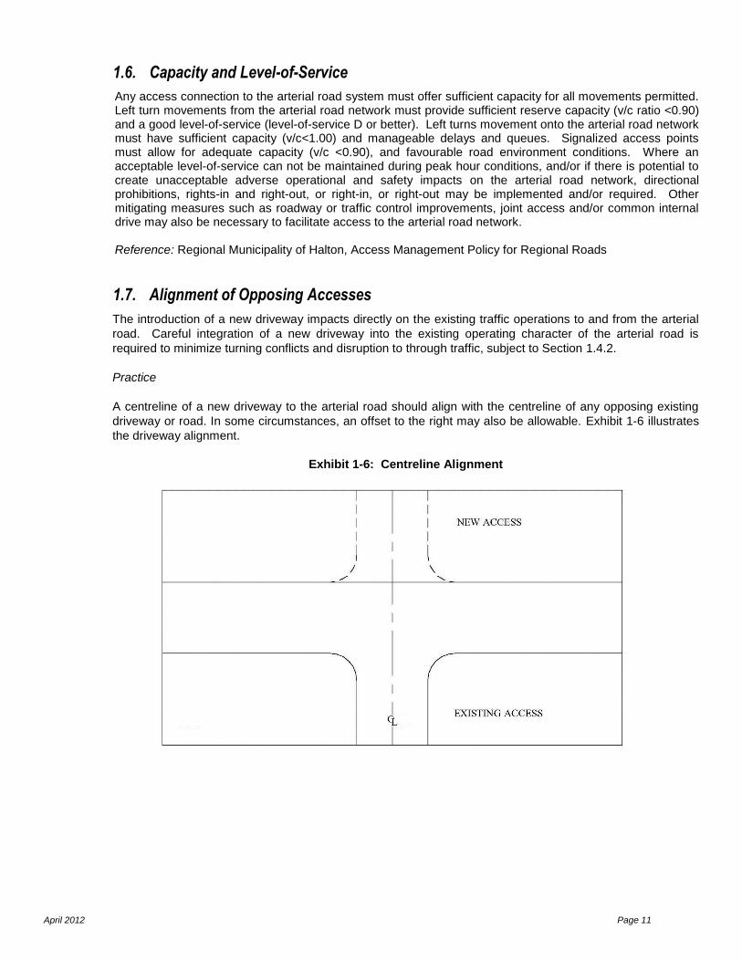
1.7. Alignment of Opposing Accesses
The introduction of a new driveway impacts directly on the existing traffic operations to and from the arterial
road. Careful integration of a new driveway into the existing operating character of the arterial road is
required to minimize turning conflicts and disruption to through traffic, subject to Section 1.4.2.
Practice
A centreline of a new driveway to the arterial road should align with the centreline of any opposing existing
driveway or road. In some circumstances, an offset to the right may also be allowable. Exhibit 1-6 illustrates
the driveway alignment.
Exhibit 1-6: Centreline Alignment
April 2012 Page 12
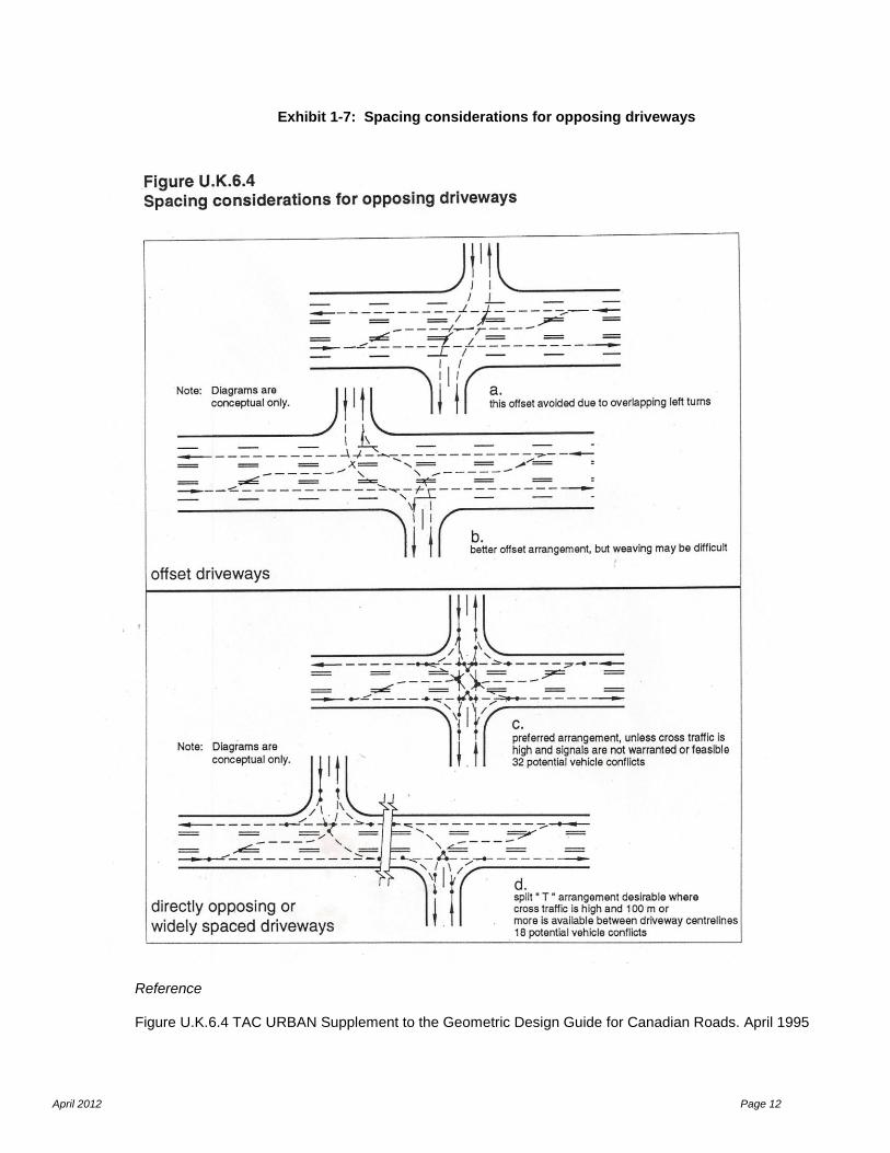
Exhibit 1-7: Spacing considerations for opposing driveways
Reference Figure U.K.6.4 TAC URBAN Supplement to the Geometric Design Guide for Canadian Roads. April 1995
April 2012 Page 13
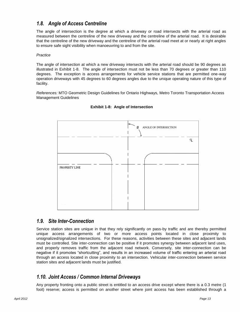
1.8. Angle of Access Centreline
The angle of intersection is the degree at which a driveway or road intersects with the arterial road as
measured between the centreline of the new driveway and the centreline of the arterial road. It is desirable
that the centreline of the new driveway and the centreline of the arterial road meet at or nearly at right angles
to ensure safe sight visibility when manoeuvring to and from the site.
Practice
The angle of intersection at which a new driveway intersects with the arterial road should be 90 degrees as
illustrated in Exhibit 1-8. The angle of intersection must not be less than 70 degrees or greater than 110
degrees. The exception is access arrangements for vehicle service stations that are permitted one-way
operation driveways with 45 degrees to 60 degrees angles due to the unique operating nature of this type of
facility.
References: MTO Geometric Design Guidelines for Ontario Highways, Metro Toronto Transportation Access
Management Guidelines
Exhibit 1-8: Angle of Intersection
1.9. Site Inter-Connection
Service station sites are unique in that they rely significantly on pass-by traffic and are thereby permitted
unique access arrangements of two or more access points located in close proximity to
unsignalized/signalized intersections. For these reasons, activities between these sites and adjacent lands
must be controlled. Site inter-connection can be positive if it promotes synergy between adjacent land uses,
and properly removes traffic from the adjacent road network. Conversely, site inter-connection can be
negative if it promotes “shortcutting”, and results in an increased volume of traffic entering an arterial road
through an access located in close proximity to an intersection. Vehicular inter-connection between service
station sites and adjacent lands must be justified.
1.10. Joint Access / Common Internal Driveways
Any property fronting onto a public street is entitled to an access drive except where there is a 0.3 metre (1
foot) reserve; access is permitted on another street where joint access has been established through a
April 2012 Page 14
consent / severance. Joint access and common internal driveways reduce the number of direct access
points to the arterial road, and minimize the opportunity for turning conflicts to occur on the municipal road
network. They are used to connect both minor and major developments and to improve driveway spacing,
which allows intensive development of a corridor, while maintaining efficient traffic operations, and safe and
convenient access to business. This type of access can also be beneficial in providing flexibility to meet local
municipal objectives relating to such things as parking, loading facilities and landscaping, with a 0.3 metre (1
foot) reserve registered on title to prevent additional property access. Where minimum access spacing
requirements cannot be achieved for a particular property adjacent to an arterial roadway, access shall be
consolidated or a joint access and/or common internal drive system shall be established or planned, provided
that the adjacent land use(s) is complementary in nature.
Proposed minor developments with arterial road frontage adjacent to complementary land uses are encouraged to implement a system of joint access and/or a common internal driveway to facilitate traffic flow between sites. Proposed major developments adjacent to an arterial road frontage are encouraged (and may be required) to implement a system of common internal drives to provide access to adjacent complementary land uses. The site design shall incorporate the following: The site plan design should clearly depict all works associated to implement the joint access; If a common internal drive is required, the plans should show all works necessary to build the drive to
the property line and including a temporary barrier to be removed when the common internal drive is constructed on the adjoining property;
A continuous service drive or common internal drive corridor extending the entire length of each block served, to provide for driveway separation consistent with this Access Guideline;
A design width sufficient to accommodate two-way travel, accommodating private automobiles, service vehicles, loading vehicles and emergency vehicles;
The design must have consideration for adequate traffic control and traffic operation, provide adequate clear throat distance between cross drive isles and the arterial road to accommodate access and egress to / from the site, and must have consideration for pedestrian connections between sites; and
Pursuant to this section of the Access Guideline, affected property owners shall:
Construct joint access in such way to allow adjacent property owner(s) to use the access for ingress and egress to and from their property;
Record an agreement that remaining access rights along the subject corridor will be dedicated to the City of London and pre-existing driveways will be closed and eliminated following construction of the joint access and common internal driveways; and
Practice
The use of mutually-shared driveway arrangements is strongly encouraged. Their use is ideal when there is
more than one business development at a given location, or a series of adjacent developments proposed
over time. This type of driveway must be registered on title of both properties in order to protect the interests
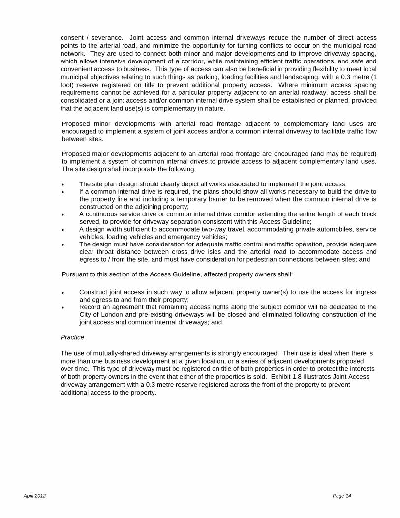
of both property owners in the event that either of the properties is sold. Exhibit 1.8 illustrates Joint Access
driveway arrangement with a 0.3 metre reserve registered across the front of the property to prevent
additional access to the property.
April 2012 Page 15
Exhibit 1-9: Joint Access
Reference: York Region Access Guideline for Regional Roads
1.11. Grade
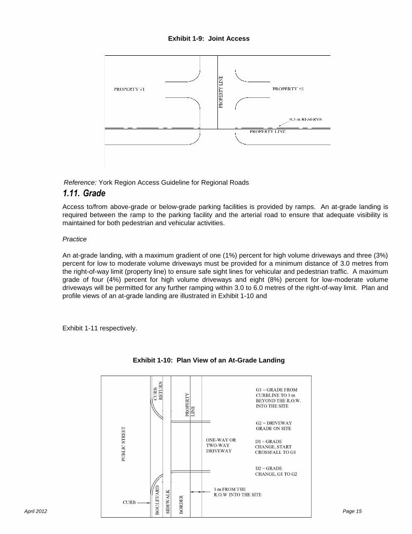
Access to/from above-grade or below-grade parking facilities is provided by ramps. An at-grade landing is
required between the ramp to the parking facility and the arterial road to ensure that adequate visibility is
maintained for both pedestrian and vehicular activities.
Practice
An at-grade landing, with a maximum gradient of one (1%) percent for high volume driveways and three (3%)
percent for low to moderate volume driveways must be provided for a minimum distance of 3.0 metres from
the right-of-way limit (property line) to ensure safe sight lines for vehicular and pedestrian traffic. A maximum
grade of four (4%) percent for high volume driveways and eight (8%) percent for low-moderate volume
driveways will be permitted for any further ramping within 3.0 to 6.0 metres of the right-of-way limit. Plan and
profile views of an at-grade landing are illustrated in Exhibit 1-10 and
Exhibit 1-11 respectively.
Exhibit 1-10: Plan View of an At-Grade Landing
April 2012 Page 16
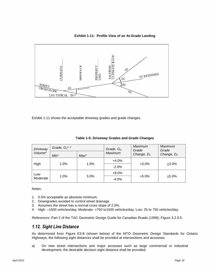
Exhibit 1-11: Profile View of an At-Grade Landing
Exhibit 1-11 shows the acceptable driveway grades and grade changes.
Table 1-5: Driveway Grades and Grade Changes
Driveway Volume4
Grade, G12, 3 Grade, G2,
Maximum
Maximum Grade Change, D1
Maximum Grade Change, D2 Min1 Max2
High 1.0% 1.0% +4.0%
+3.0% +3.0% -2.0%
Low-Moderate
1.0% 3.0% +8.0%
+5.0% +5.0% -4.0%
Notes:
1. 0.5% acceptable as absolute minimum.
2. Downgrades avoided to control street drainage.
3. Assumes the street has a normal cross slope of 2.0%.
4. High: 1500 vehicles/day; Moderate: >750 to1500 vehicles/day; Low: 25 to 750 vehicles/day.
References: Part 2 of the TAC Geometric Design Guide for Canadian Roads (1999), Figure 3.2.9.5.
1.12. Sight Line Distance
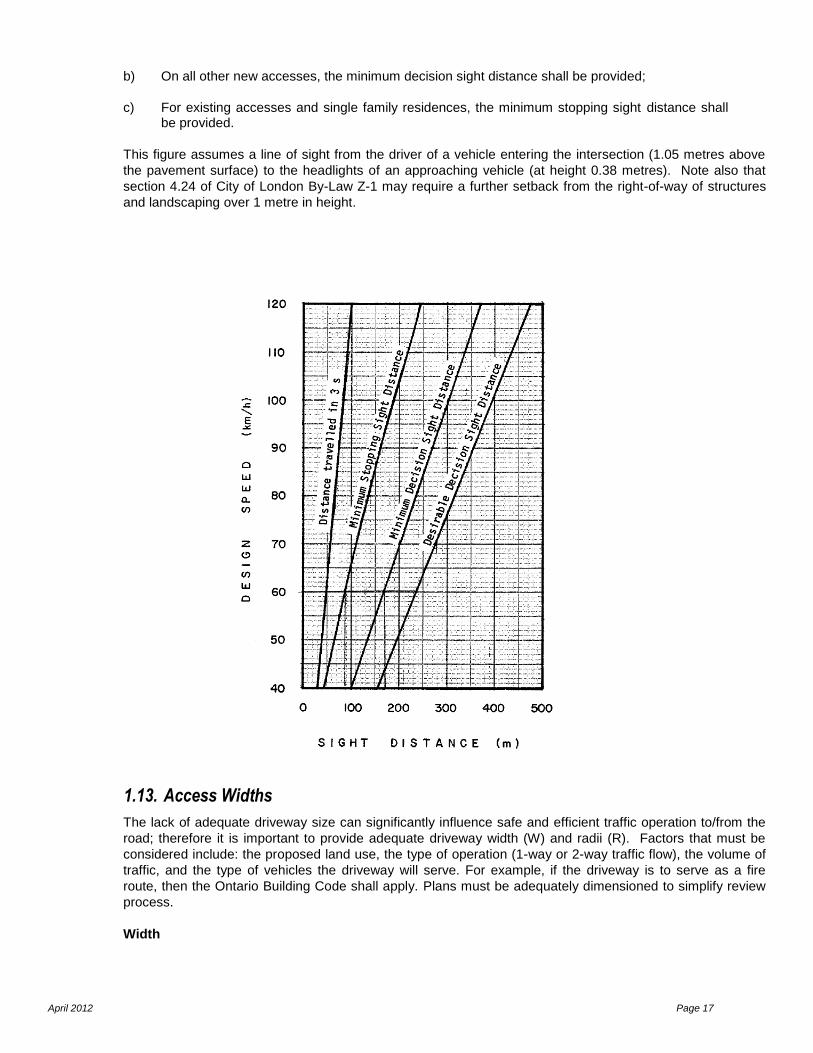
As determined from Figure E3-8 (shown below) of the MTO Geometric Design Standards for Ontario
Highways, the following sight distances shall be provided at intersections and accesses:
a) On new street intersections and major accesses such as large commercial or industrial development, the desirable decision sight distance shall be provided;
April 2012 Page 17
b) On all other new accesses, the minimum decision sight distance shall be provided;
c) For existing accesses and single family residences, the minimum stopping sight distance shall be provided.
This figure assumes a line of sight from the driver of a vehicle entering the intersection (1.05 metres above
the pavement surface) to the headlights of an approaching vehicle (at height 0.38 metres). Note also that
section 4.24 of City of London By-Law Z-1 may require a further setback from the right-of-way of structures
and landscaping over 1 metre in height.
1.13. Access Widths
The lack of adequate driveway size can significantly influence safe and efficient traffic operation to/from the
road; therefore it is important to provide adequate driveway width (W) and radii (R). Factors that must be
considered include: the proposed land use, the type of operation (1-way or 2-way traffic flow), the volume of
traffic, and the type of vehicles the driveway will serve. For example, if the driveway is to serve as a fire
route, then the Ontario Building Code shall apply. Plans must be adequately dimensioned to simplify review
process.
Width

April 2012 Page 18
Driveway width (W) should be restrictive enough to discourage erratic manoeuvres, control the location and
angle of conflict points, and limit entry/exit to the intended number of lanes of operation. Whether a driveway
will operate with one-way or two-way traffic flow must also be considered.
One-Way Driveway
A one-way driveway operates with a single entry or exit lane, as illustrated in Exhibit 1-12.
Practice
The minimum width of a one-way driveway measured at the throat ranges from 3.0 metres to 5.0 metres depending on the land use of the development, as outlined in Table 1-6.
Two-Way Driveway
A two-way driveway operates with at least one entry and one exit lane through a single driveway point, as
illustrated in Exhibit 1-12.
Practice
The minimum width of a two-way driveway, measured at the throat, ranges from 6.0 metres to 9.0 metres depending on the land use of the development, as outlined in Table 1-6.
Exhibit 1-12: Driveway Layouts
April 2012 Page 19
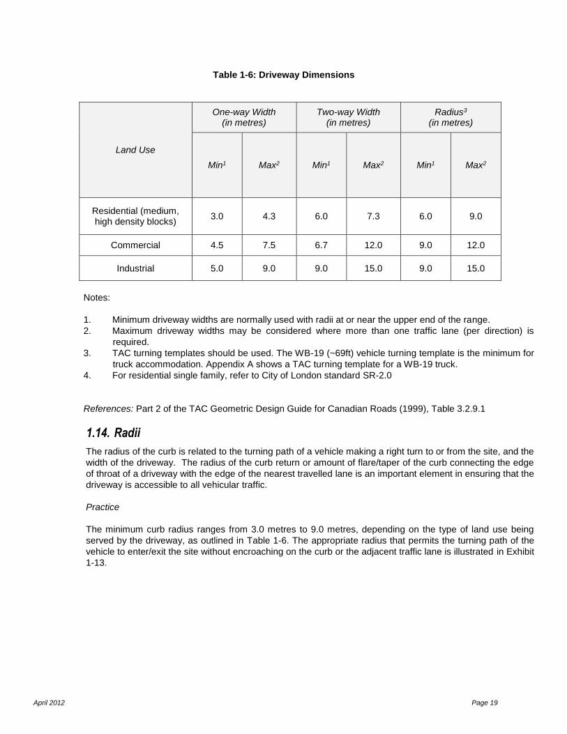
Table 1-6: Driveway Dimensions
Land Use
One-way Width (in metres)
Two-way Width (in metres)
Radius3 (in metres)
Min1 Max2 Min1 Max2 Min1 Max2
Residential (medium, high density blocks)
3.0 4.3 6.0 7.3 6.0 9.0
Commercial 4.5 7.5 6.7 12.0 9.0 12.0
Industrial 5.0 9.0 9.0 15.0 9.0 15.0
Notes:
1. Minimum driveway widths are normally used with radii at or near the upper end of the range.
2. Maximum driveway widths may be considered where more than one traffic lane (per direction) is
required.
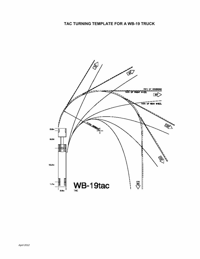
3. TAC turning templates should be used. The WB-19 (~69ft) vehicle turning template is the minimum for
truck accommodation. Appendix A shows a TAC turning template for a WB-19 truck.
4. For residential single family, refer to City of London standard SR-2.0
References: Part 2 of the TAC Geometric Design Guide for Canadian Roads (1999), Table 3.2.9.1
1.14. Radii
The radius of the curb is related to the turning path of a vehicle making a right turn to or from the site, and the
width of the driveway. The radius of the curb return or amount of flare/taper of the curb connecting the edge
of throat of a driveway with the edge of the nearest travelled lane is an important element in ensuring that the
driveway is accessible to all vehicular traffic.
Practice
The minimum curb radius ranges from 3.0 metres to 9.0 metres, depending on the type of land use being
served by the driveway, as outlined in Table 1-6. The appropriate radius that permits the turning path of the
vehicle to enter/exit the site without encroaching on the curb or the adjacent traffic lane is illustrated in Exhibit
1-13.
April 2012 Page 20
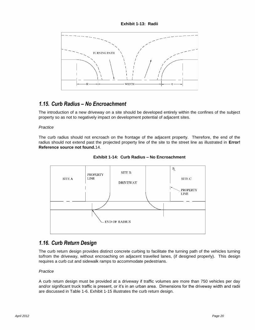
Exhibit 1-13: Radii
1.15. Curb Radius – No Encroachment
The introduction of a new driveway on a site should be developed entirely within the confines of the subject
property so as not to negatively impact on development potential of adjacent sites.
Practice
The curb radius should not encroach on the frontage of the adjacent property. Therefore, the end of the
radius should not extend past the projected property line of the site to the street line as illustrated in Error!
Reference source not found.14.
Exhibit 1-14: Curb Radius – No Encroachment
1.16. Curb Return Design
The curb return design provides distinct concrete curbing to facilitate the turning path of the vehicles turning
to/from the driveway, without encroaching on adjacent travelled lanes, (if designed properly). This design
requires a curb cut and sidewalk ramps to accommodate pedestrians.
Practice
A curb return design must be provided at a driveway if traffic volumes are more than 750 vehicles per day
and/or significant truck traffic is present, or it’s in an urban area. Dimensions for the driveway width and radii
are discussed in Table 1-6. Exhibit 1-15 illustrates the curb return design.
April 2012 Page 21
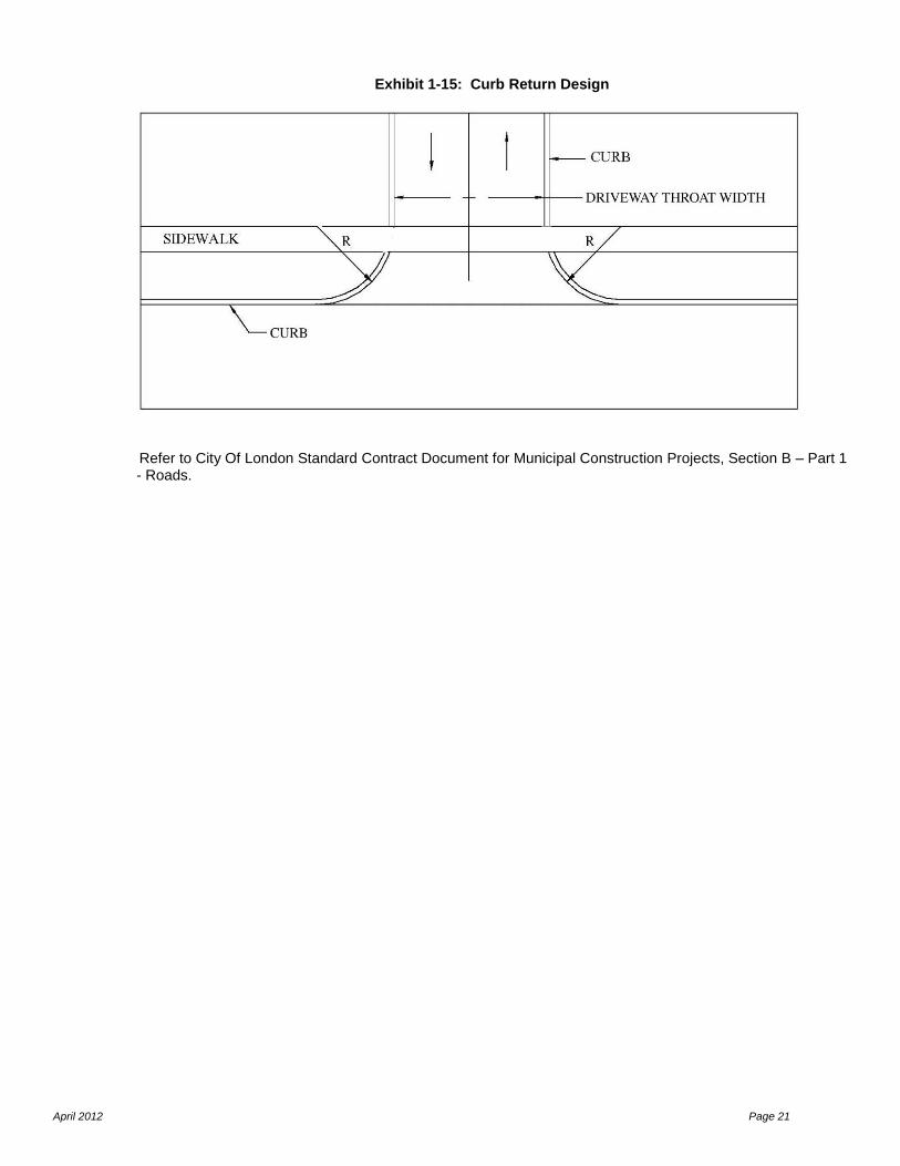
Exhibit 1-15: Curb Return Design
Refer to City Of London Standard Contract Document for Municipal Construction Projects, Section B – Part 1 - Roads.

April 2012 Page 22
2. ACCESS TURNING RESTRICTIONS
2.1. Operating Requirements
Turning movements must be controlled when safe and efficient traffic operations cannot be maintained
between the arterial road or Primary Collector road and the proposed driveway. There are two methods of
controlling turning activities: (a) turn prohibitions and (b) turn restrictions.
Turn prohibitions are controlled with the enactment of by-laws accompanied by appropriate signage.
Turn restrictions are additionally controlled by geometric improvements to physically prohibit the specific
turning movement(s).
The enforcement of by-laws is difficult and, therefore, physical barriers are often required to provide an effective means of ensuring compliance with turning controls. The installation of concrete islands/medians physically prevents the specific turning movement(s) and directs vehicles into the defined turning paths. At some access points, full movements may be allowed in the short term, however the City may require that the owner accept that turning movements may be restricted in the future due to increased traffic volumes and/or safety concerns. The installation of Rights-In Rights-out islands (“Pork Chop”) is proven to be ineffective for restricting left turning movements to and from access point and not typically supported by the City. However, in some locations it is very difficult and/or impossible to implement on street raised concrete median and Rights-in Rights-out island may be considered (Must be approved by Transportation Planning and Design Division).
Practice
Specific turning movements to/from a driveway will be controlled if the turning movements cannot be
executed safely and efficiently with minimal disruption to traffic operations on the arterial or primary
collector road.
The criteria used to determine when turning control restrictions will be required are as follows:
An inbound left turn level-of-service (LOS) E or worse and v/c ratio => 0.9 during peak periods.
An outbound left turn level-of-service (LOS) E or worse and a v/c ratio => 0.9 during peak
periods.
Adequate spacing between driveways is not provided (refer to Section 1.4 of this manual) to
ensure that left turn conflicts are minimal.
Minimum safe sight distances must be maintained in order to execute the anticipated turning
movements while minimizing interference with existing traffic operations on the arterial road.
References
TAC Geometric Design Guide for Canadian Roads, Section 3.2.9 of Part 2.
ITE Transportation and Land Development, Chapter 5: Principles of Access Design, page 22.
April 2012 Page 23
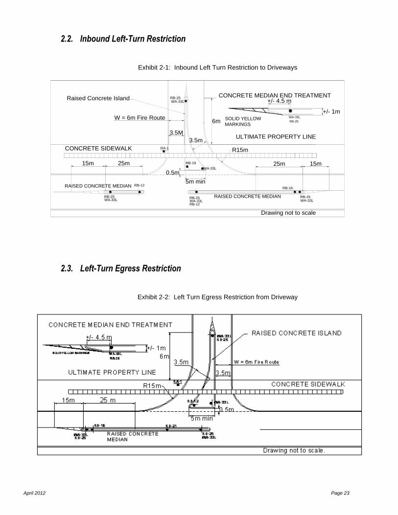
2.2. Inbound Left-Turn Restriction
Exhibit 2-1: Inbound Left Turn Restriction to Driveways
WA-33LRB-25
RA-1
WA-33L WA-33L
RB-16
WA-33L
RB-12
CONCRETE SIDEWALK
3.5m
15m25m
6m
R15m
5m min
0.5m
RAISED CONCRETE MEDIAN
ULTIMATE PROPERTY LINE
CONCRETE MEDIAN END TREATMENT
RB-19
RB-25RB-25WA-33LRB-25
W = 6m Fire Route
Drawing not to scale
WA-33L
RB-25SOLID YELLOW
MARKINGS
+/- 4.5 m
+/- 1m
Raised Concrete Island
3.5M
RAISED CONCRETE MEDIAN
25m15m
RB-12
2.3. Left-Turn Egress Restriction
Exhibit 2-2: Left Turn Egress Restriction from Driveway

April 2012 Page 24
2.4. Rights-In / Rights-Out
Exhibit 2-3: Both Left Turns Restricted
RA-1
WA-33L
RB-16RB-21
CONCRETE SIDEWALK
15m25m
RAISED CONCRETE MEDIAN
ULTIMATE PROPERTY LINE
CONCRETE MEDIAN END TREATMENT
RB-25WA-33LRB-25
Drawing not to scale
WA-33L
RB-25SOLID YELLOW
MARKINGS
+/- 4.5 m
+/- 1m
25m15m
RB-16
2.5. Rights-In / Rights-Out “Pork Chop”
Exhibit 2-4: Both Left Turns Restricted
WA-33LRB-25
RA-1
WA-33L
CONCRETE SIDEWALK R15m
10m min
0.5
m
ULTIMATE PROPERTY LINE
CONCRETE MEDIAN END TREATMENT
RB-12
Drawing not to scale
WA-33L
RB-25SOLID YELLOW MARKINGS
+/- 4.5 m
+/-
1m
Raised Concrete Island
(min size=30m2)
R15m
Fire Route concrete rumble strips
3.5m
3.5m
2.5m
2.5m
Fire Route Driveway Widths 6m
(3.5m asphalt,2.5m concrete rumble strips)
otherwiseW=3.5m in and W=3.5m out
Road C/L
RB-19RB-12
RB-12
The use of trees and/or landscape materials in centre medians and in some cases rights-in rights-out islands is encouraged when possible, providing adequate sight distance at driveway access connections is maintained, and to be reviewed and approved by the City during Site Plan Approval Process.

April 2012 Page 25
3. ROADWAY FEATURES 3.1. Left Turn Lane
The left turn lane requirements for two-lane, four-lane, and six-lane divided and undivided roadways shall be
based on volume warrants and collision warrants as identified by an accepted transportation impact study.
3.1.1 Volume Warrant
Practice
When opposing traffic volumes are such that left turning vehicles must wait for a gap to make their turn, they
interfere with the through traffic. The magnitude of this interference depends on the opposing volume, the
advancing volume and the percentage of left turning vehicles.
When traffic signals are warranted, storage lengths are subject to signal cycle timing. Volume warrants for
left turns are based upon capacity calculations for intersections.
References
Part 2 of the TAC Geometric Design Guide for Canadian Roads (1999), Page 2.3.8.1
3.1.2 Col lision Warrant
Practice
A left turn storage lane may be considered at locations where four or more collisions related to left turns
occur per year or where six or more occur within a period of two years, provided the collisions are of a type
which could reasonably be expected to be eliminated by provision of a left turn lane. The minimum storage
length for the collision warrant is 15 m.
References
Part 2 of the TAC Geometric Design Guide for Canadian Roads (1999), Page 2.3.8.1
3.2. Right-Turn Lane
Practice
Although right turns are generally made more efficiently than left turn movements, exclusive right turn lanes
are often provided, for many of the same reasons that left turn lanes are provided. Right turns may face a
conflicting pedestrian flow, but do not face a conflicting vehicular flow. In general, an exclusive right turn lane
should be considered when the volume of right turning vehicles is between 10 to 20 percent of the through
volume, subject to a minimum of 60 vehicles per hour in the design hour. Design speed should be
considered when determining right-turn requirements.
TAC recommends the use of an exclusive right turn lane when the volume of decelerating or accelerating
vehicles compared with the through traffic volume causes undue hazard.
References
Highway Capacity Manual, Special Report 209, Third Edition (1998) by Transportation Research Board,
National Research Council, Washington, Page 9-97.
April 2012 Page 26
3.3. Medians
Practice
A median may be defined as that portion of a road that physically separates the travel lanes of traffic in
opposing directions. Median width is the lateral dimension measured between the inner (left) edges of the
travel lanes and includes the left shoulder, the gutter or offset widths.
A median is a safety device that provides some measure of freedom from conflicting vehicular movements.
The major uses of a median separation are to eliminate the risk of head-on collisions, and to reduce the risk
of right angle collisions by controlling access.
A centre median is more effective than “pork chop” islands (See Exhibit 2-33) in enforcing right-in, right-out
only access operations. While there are multiple causes that lead to the consideration of a median, it should
be noted that ultimately, the primary intent of installing a median is improved safety. The installation of a
centre median should be considered if:
There is a history of right angle collisions in the vicinity of existing or proposed accesses;
The left-out Level of Service is E or worse;
If the queues on the adjacent roadway during one or more of the peak periods typically extend
past the proposed location of the access;
There is a series of closely spaced accesses;
There is insufficient right-of-way to implement a two-way centre left turn lane, or, there is an
existing two-way centre left turn lane, but with a history of right angle collisions;
While considering a centre median, thought should also be given to the effect of that median on adjacent or
opposite properties.
Median widths may be as narrow as 1.0 metres as per Ontario Provincial Standard Drawing (OPSD). There
must be 25 meters of upstream and downstream median length, measured from the back edge of radii (Refer
to Figures 2.1., 2.2., 2.3., 2.4.) or as determined otherwise.
3.4. Signal Warrant
Signalization of a private access is normally considered in the context of a traffic impact report of a major
development. Traffic signals shall be considered warranted if intersection conditions meet or exceed the
warrant requirements of the Ontario Traffic Manual Book 12 as determined by a traffic survey. Minimum
signal spacing requirements as identified under Section 1.4 “Spacing Requirements of Major Driveways and
Intersection Spacing.”
3.5. Bus Bays
Bus Bays for London Transit vehicles may be a required improvement to street-side bus stops along arterial
roadways. City administration will inform the developer if an existing transit stop in proximity to a
development must be re-designed as transit bus bay.
3.5.1 Structure
Bus bays shall be constructed with a 200mm thick finished concrete surface and a 200mm thick Granular ‘A’
base. If the sub-grade is a weak or clayey material then a 300mm thick sub-base shall be added.
April 2012 Page 27
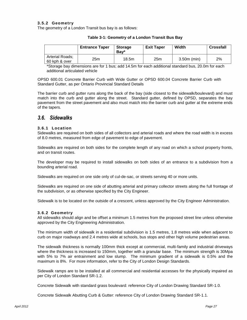
3.5.2 Geometry
The geometry of a London Transit bus bay is as follows:
Table 3-1: Geometry of a London Transit Bus Bay
Entrance Taper Storage Bay*
Exit Taper Width Crossfall
Arterial Roads; 60 kph & over
25m 18.5m 25m 3.50m (min) 2%
*Storage bay dimensions are for 1 bus; add 14.5m for each additional standard bus, 20.0m for each additional articulated vehicle
OPSD 600.01 Concrete Barrier Curb with Wide Gutter or OPSD 600.04 Concrete Barrier Curb with Standard Gutter, as per Ontario Provincial Standard Details The barrier curb and gutter runs along the back of the bay (side closest to the sidewalk/boulevard) and must match into the curb and gutter along the street. Standard gutter, defined by OPSD, separates the bay pavement from the street pavement and also must match into the barrier curb and gutter at the extreme ends of the tapers.
3.6. Sidewalks
3.6.1 Location
Sidewalks are required on both sides of all collectors and arterial roads and where the road width is in excess
of 8.0 metres, measured from edge of pavement to edge of pavement.
Sidewalks are required on both sides for the complete length of any road on which a school property fronts,
and on transit routes.
The developer may be required to install sidewalks on both sides of an entrance to a subdivision from a
bounding arterial road.
Sidewalks are required on one side only of cul-de-sac, or streets serving 40 or more units.
Sidewalks are required on one side of abutting arterial and primary collector streets along the full frontage of
the subdivision, or as otherwise specified by the City Engineer.
Sidewalk is to be located on the outside of a crescent, unless approved by the City Engineer Administration.
3.6.2 Geometry
All sidewalks should align and be offset a minimum 1.5 metres from the proposed street line unless otherwise
approved by the City Engineering Administration.
The minimum width of sidewalk in a residential subdivision is 1.5 metres, 1.8 metres wide when adjacent to
curb on major roadways and 2.4 metres wide at schools, bus stops and other high volume pedestrian areas.
The sidewalk thickness is normally 100mm thick except at commercial, multi-family and industrial driveways
where the thickness is increased to 150mm, together with a granular base. The minimum strength is 30Mpa
with 5% to 7% air entrainment and low slump. The minimum gradient of a sidewalk is 0.5% and the
maximum is 8%. For more information, refer to the City of London Design Standards.
Sidewalk ramps are to be installed at all commercial and residential accesses for the physically impaired as
per City of London Standard SR-1.2.
Concrete Sidewalk with standard grass boulevard: reference City of London Drawing Standard SR-1.0.
Concrete Sidewalk Abutting Curb & Gutter: reference City of London Drawing Standard SR-1.1.

April 2012 Page 28
3.7. Bicycle Paths
Historically the City has supported the creation of In Boulevard Bicycle Paths (IBBP’s) which are exclusive
bicycle pathways located within specified arterial road right-of-ways, typically between the sidewalk and the
curb lane of the traveled portion of the road. The City of London Bicycle Master Plan advocates a departure
from this practice of providing for IBBP’s along arterial corridors.
The Bicycle Master Plan identifies which arterial and collector corridors will become travel routes for cycling
commuters. The bicycle routes have two classes: primary commuter routes and secondary commuter
routes.
The City of London Bicycle Design Guidelines has two distinct design standards for cycling routes. The On-
Road bicycle commuter route is a separate pavement-marked lane. The Widened Curb Lane provides extra
pavement width that is not pavement-marked but is indicated as a commuter route with signage. More
information can be found in the Bicycle Master Plan and City of London Bicycle Design Guidelines.
April 2012 Page 29
4. PARKING OPERATIONS
4.1. Clear Throat Distance
Clear throat distance is the length required on the driveway to store vehicles waiting to circulate into the site,
usually a parking area. Failure to provide an adequate clear throat distance can create congestion and
operational concerns on the arterial road, as well as safety concerns for pedestrians attempting to cross the
driveway. Other locations requiring clear throat distance are at drive-through restaurants, drive-through bank
machines and convenience stores. Drive-through windows may require an internal stacking lane.
The amount of clear throat distance is directly related to the required capacity of the parking lot.
Practice
The minimum amount of desirable clear throat distance is a tangent line measured from or past the ultimate
right-of-way limit between the designated points where turns are permitted, and the length of the clear throat
depends on the number of parking spaces provided on the site, as outlined in Table 4-1. This applies to both
inbound traffic as well as outbound traffic.
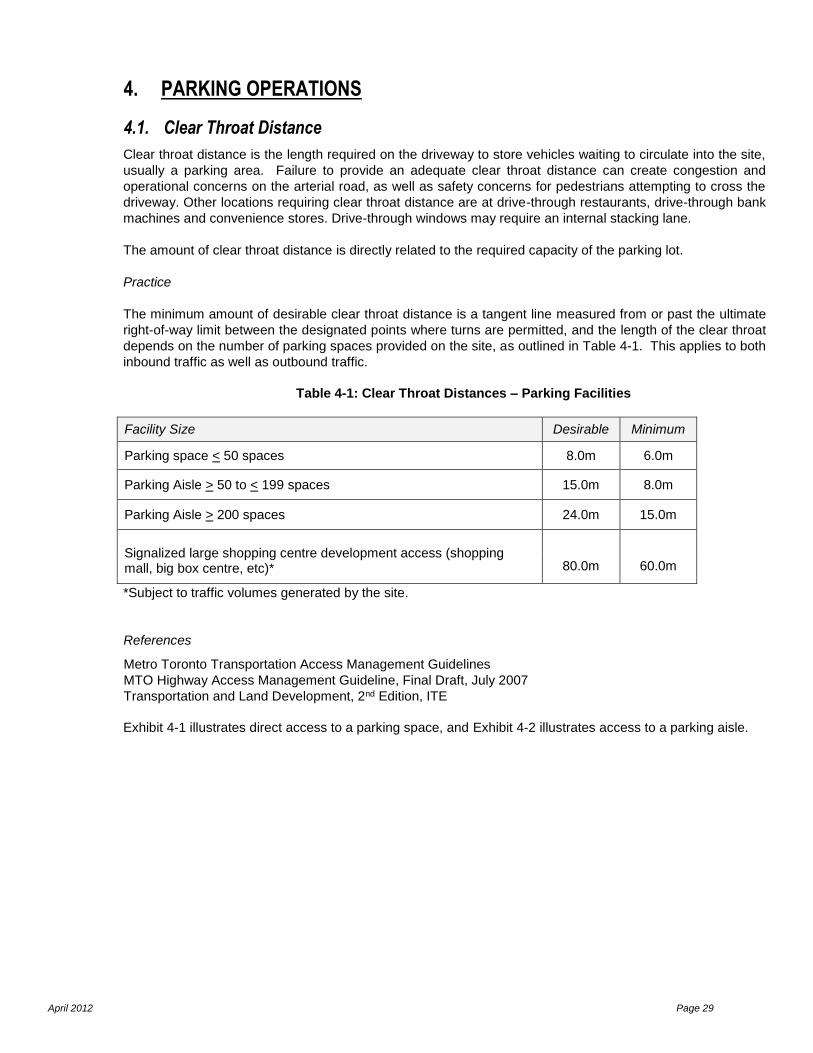
Table 4-1: Clear Throat Distances – Parking Facilities
Facility Size Desirable Minimum
Parking space < 50 spaces 8.0m 6.0m
Parking Aisle > 50 to < 199 spaces 15.0m 8.0m
Parking Aisle > 200 spaces 24.0m 15.0m
Signalized large shopping centre development access (shopping mall, big box centre, etc)*
80.0m 60.0m
*Subject to traffic volumes generated by the site.
References
Metro Toronto Transportation Access Management Guidelines
MTO Highway Access Management Guideline, Final Draft, July 2007
Transportation and Land Development, 2nd Edition, ITE
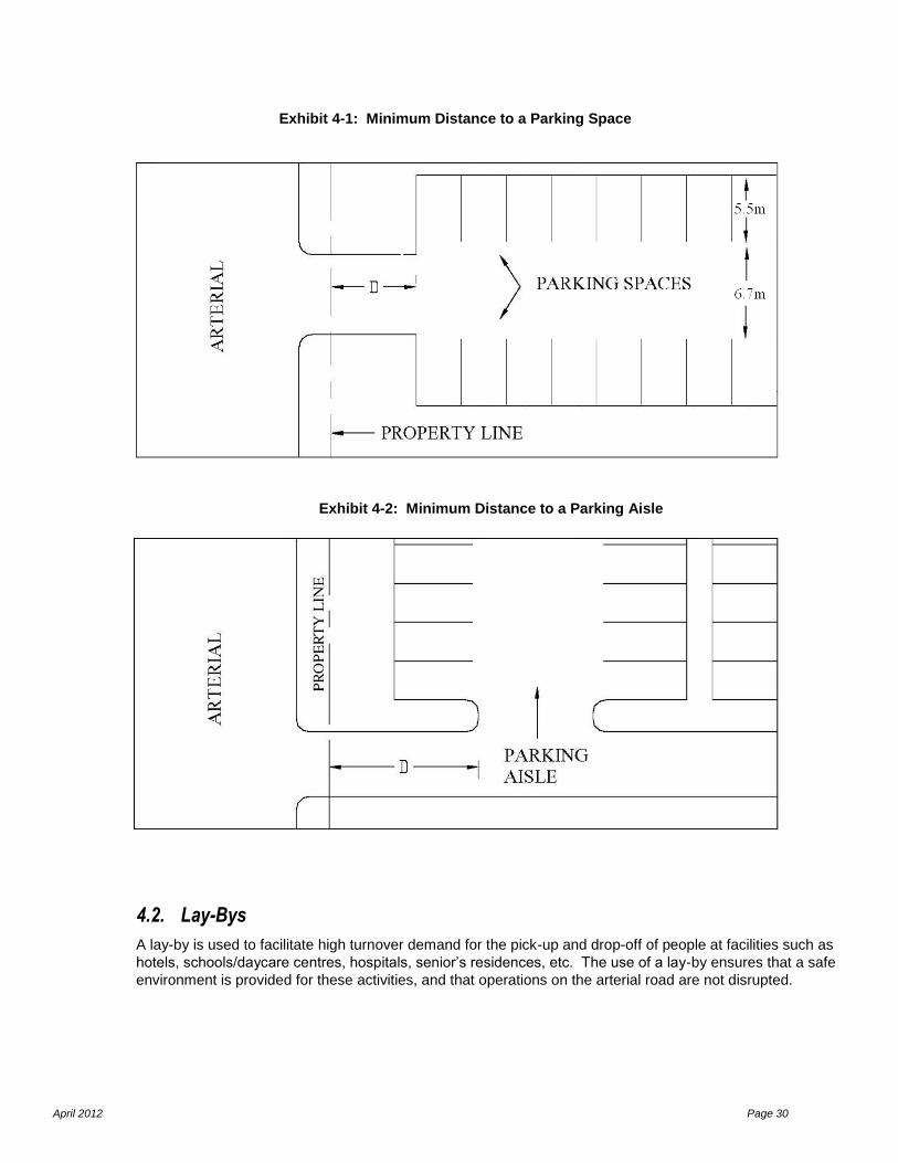
Exhibit 4-1 illustrates direct access to a parking space, and Exhibit 4-2 illustrates access to a parking aisle.
April 2012 Page 30
Exhibit 4-1: Minimum Distance to a Parking Space
Exhibit 4-2: Minimum Distance to a Parking Aisle
4.2. Lay-Bys
A lay-by is used to facilitate high turnover demand for the pick-up and drop-off of people at facilities such as
hotels, schools/daycare centres, hospitals, senior’s residences, etc. The use of a lay-by ensures that a safe
environment is provided for these activities, and that operations on the arterial road are not disrupted.

April 2012 Page 31
Practice
A lay-by will only be considered to facilitate the high turnover demand of person activities on sites that meet
the following criteria:
It must be demonstrated that the need for the lay-by facility is justified for its intended purpose,
and that traffic operations on the arterial road will not be disrupted;
Sufficient stacking space should be provided to accommodate the peak pick-up and drop-off
demands. This should be demonstrated as part of the Traffic Impact Study;
The operation of the lay-by must be restricted to one-way movements to avoid any vehicle
reversing movements. The turning movements permitted to and from the access points will be
determined on a site-specific basis using the applicable site operations standards;
The lay-by must be provided exclusively on private property; and
Sufficient width must be provided for one vehicle to pass another.
Exhibit 4-3: Lay-by and Passenger Drop-off Zone
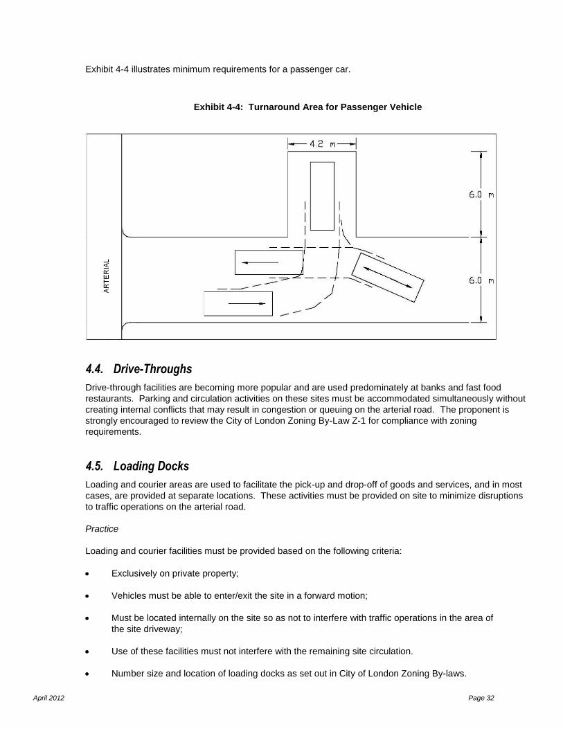
4.3. Turnaround Areas
A turnaround area is a designated area on a site, which is used when no parking spaces are available, to
facilitate turning around so that vehicles exit the site in a forward motion.
Practice
A designated turnaround area must be provided on site so that vehicles may exit the site in a forward motion
onto the arterial road. The minimum size of the turnaround area (for the purposes of a passenger car) is 4.2
metres by 6.0 metres. Transportation Association of Canada (TAC) templates must be used to ensure that
an appropriate turning path is available to execute the turning manoeuvres.
April 2012 Page 32
Exhibit 4-4 illustrates minimum requirements for a passenger car.
Exhibit 4-4: Turnaround Area for Passenger Vehicle
4.4. Drive-Throughs
Drive-through facilities are becoming more popular and are used predominately at banks and fast food
restaurants. Parking and circulation activities on these sites must be accommodated simultaneously without
creating internal conflicts that may result in congestion or queuing on the arterial road. The proponent is
strongly encouraged to review the City of London Zoning By-Law Z-1 for compliance with zoning
requirements.
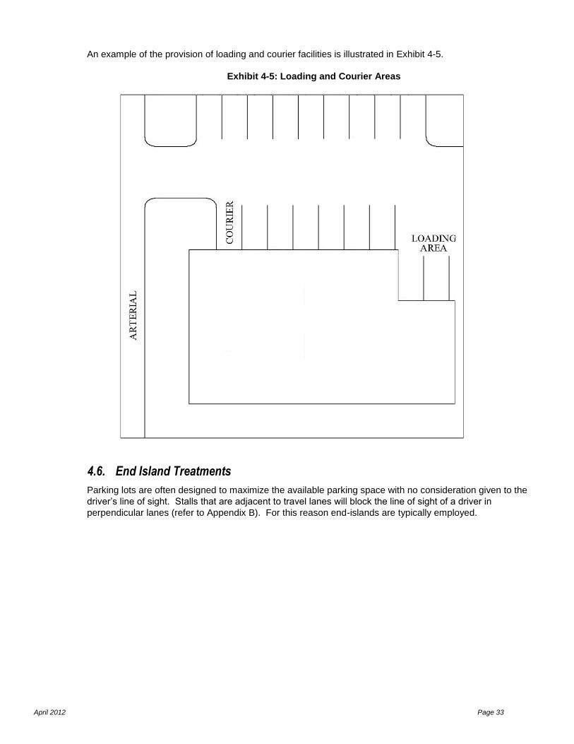
4.5. Loading Docks
Loading and courier areas are used to facilitate the pick-up and drop-off of goods and services, and in most
cases, are provided at separate locations. These activities must be provided on site to minimize disruptions
to traffic operations on the arterial road.
Practice
Loading and courier facilities must be provided based on the following criteria:
Exclusively on private property;
Vehicles must be able to enter/exit the site in a forward motion;
Must be located internally on the site so as not to interfere with traffic operations in the area of
the site driveway;
Use of these facilities must not interfere with the remaining site circulation.
Number size and location of loading docks as set out in City of London Zoning By-laws.
April 2012 Page 33
An example of the provision of loading and courier facilities is illustrated in Exhibit 4-5.
Exhibit 4-5: Loading and Courier Areas
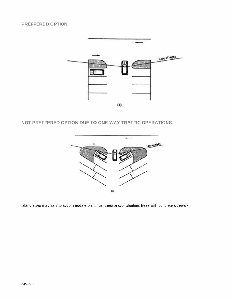
4.6. End Island Treatments
Parking lots are often designed to maximize the available parking space with no consideration given to the
driver’s line of sight. Stalls that are adjacent to travel lanes will block the line of sight of a driver in
perpendicular lanes (refer to Appendix B). For this reason end-islands are typically employed.
City of London ACCESS MANAGEMENT GUIDELINES
April 2012
APPENDIX A
TURNING TEMPLATE
April 2012
TAC TURNING TEMPLATE FOR A WB-19 TRUCK
April 2012
APPENDIX B
END ISLAND TREATMENTS ABUTING INTERNAL DRIVES
April 2012
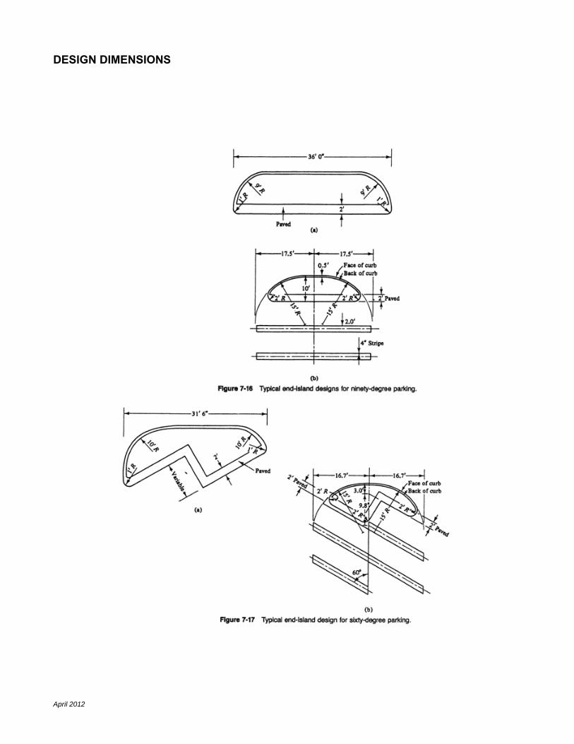
DESIGN DIMENSIONS
April 2012
PREFFERED OPTION
NOT PREFFERED OPTION DUE TO ONE-WAY TRAFFIC OPERATIONS
Island sizes may vary to accommodate plantings, trees and/or planting, trees with concrete sidewalk.