Access Gateway Administrators Guide, 7.3 - Fujitsu...
104
53-1003126-02 15 August 2014 Access Gateway Administrator's Guide Supporting Fabric OS v7.3.0
Transcript of Access Gateway Administrators Guide, 7.3 - Fujitsu...
53-1003126-0215 August 2014
Access GatewayAdministrator's Guide
Supporting Fabric OS v7.3.0

© 2014, Brocade Communications Systems, Inc. All Rights Reserved.
Brocade, the B-wing symbol, Brocade Assurance, ADX, AnyIO, DCX, Fabric OS, FastIron, HyperEdge, ICX, MLX, MyBrocade, NetIron,OpenScript, VCS, VDX, and Vyatta are registered trademarks, and The Effortless Network and the On-Demand Data Center are trademarksof Brocade Communications Systems, Inc., in the United States and in other countries. Other brands and product names mentioned may betrademarks of others.
Notice: This document is for informational purposes only and does not set forth any warranty, expressed or implied, concerning anyequipment, equipment feature, or service offered or to be offered by Brocade. Brocade reserves the right to make changes to this documentat any time, without notice, and assumes no responsibility for its use. This informational document describes features that may not becurrently available. Contact a Brocade sales office for information on feature and product availability. Export of technical data contained inthis document may require an export license from the United States government.
The authors and Brocade Communications Systems, Inc. assume no liability or responsibility to any person or entity with respect to theaccuracy of this document or any loss, cost, liability, or damages arising from the information contained herein or the computer programs thataccompany it.
The product described by this document may contain open source software covered by the GNU General Public License or other opensource license agreements. To find out which open source software is included in Brocade products, view the licensing terms applicable tothe open source software, and obtain a copy of the programming source code, please visit http://www.brocade.com/support/oscd.

Contents
Preface..................................................................................................................................... 7Document conventions......................................................................................7
Text formatting conventions.................................................................. 7Command syntax conventions.............................................................. 7Notes, cautions, and warnings.............................................................. 8
Brocade resources............................................................................................ 9Contacting Brocade Technical Support.............................................................9Document feedback........................................................................................ 10
About This Document.............................................................................................................. 11Supported hardware and software.................................................................. 11What’s new in this document.......................................................................... 11Key terms for Access Gateway....................................................................... 12
Access Gateway Basic Concepts..............................................................................................15Brocade Access Gateway overview ...............................................................15
Comparing Native Fabric and Access Gateway modes......................15Fabric OS features in Access Gateway mode................................................ 17
Buffer credit recovery support............................................................. 20Forward error correction support.........................................................20Virtual Fabrics support........................................................................ 21Device authentication support.............................................................21AG mode without all POD licenses..................................................... 23Password distribution support............................................................. 23FDMI support...................................................................................... 24
Access Gateway port types.............................................................................24Comparison of Access Gateway ports to standard switch ports ........ 24
Access Gateway hardware considerations..................................................... 26
Configuring Ports in Access Gateway Mode..............................................................................27Enabling and disabling Access Gateway mode.............................................. 27
Port state description.......................................................................... 28Access Gateway mapping...............................................................................29
Port mapping.......................................................................................29F_Port Static Mapping.........................................................................36Device mapping.................................................................................. 37Considerations for Access Gateway mapping.................................... 44
N_Port configurations......................................................................................46Displaying N_Port configurations........................................................ 47Unlocking N_Ports ............................................................................. 47Persisting port online state .................................................................47
D_Port support................................................................................................ 48Limitations and considerations............................................................48Saving port mappings ........................................................................ 49
Managing Policies and Features in Access Gateway Mode....................................................... 51
Access Gateway Administrator's Guide 353-1003126-02

Access Gateway policies overview............................................................... 51Displaying current policies ............................................................... 51Access Gateway policy enforcement matrix .................................... 51
Advanced Device Security policy .................................................................52How the ADS policy works................................................................52Enabling and disabling the ADS policy............................................. 52Allow lists.......................................................................................... 53ADS policy considerations................................................................ 55Upgrade and downgrade considerations for the ADS policy............ 55
Automatic Port Configuration policy .............................................................55How the APC policy works................................................................55Enabling and disabling the APC policy............................................. 55APC policy considerations................................................................ 56Upgrade and downgrade considerations for the APC policy............ 56
Port Grouping policy......................................................................................56How port groups work....................................................................... 57Adding an N_Port to a port group..................................................... 58Deleting an N_Port from a port group............................................... 58Removing a port group .....................................................................58Renaming a port group..................................................................... 59Disabling the Port Grouping policy....................................................59Port Grouping policy modes..............................................................59Creating a port group and enabling Automatic Login Balancing
mode............................................................................................60Enabling MFNM mode...................................................................... 61Disabling MFNM mode......................................................................61Displaying the current MFNM mode timeout value........................... 61Setting the current MFNM mode timeout value.................................61Port Grouping policy considerations................................................. 61Upgrade and downgrade considerations for the Port Grouping
policy........................................................................................... 62Device Load Balancing policy....................................................................... 62
Enabling the Device Load Balancing policy...................................... 62Disabling the Device Load Balancing policy..................................... 63Device Load Balancing policy considerations...................................63
Persistent ALPA policy..................................................................................63Enabling the Persistent ALPA policy.................................................64Disabling the Persistent ALPA policy................................................64Persistent ALPA device data.............................................................64Clearing ALPA values....................................................................... 65Persistent ALPA policy considerations..............................................65
Failover policy............................................................................................... 65Failover with port mapping................................................................66Failover with device mapping ...........................................................69Enabling and disabling the Failover policy on an N_Port..................70Enabling and disabling the Failover policy for a port group.............. 71Upgrade and downgrade considerations for the Failover policy....... 71
Failback policy...............................................................................................71Failback policy configurations in Access Gateway............................72Enabling and disabling the Failback policy on an N_Port ................ 73Enabling and disabling the Failback policy for a port group..............74Upgrade and downgrade considerations for the Failback policy...... 74Failback policy disabled on unreliable links (N_Port monitoring)......74
Trunking in Access Gateway mode...............................................................75How trunking works...........................................................................75Configuring trunking on the Edge switch.......................................... 75Configuration management for trunk areas...................................... 76Enabling trunking ............................................................................. 77
4 Access Gateway Administrator's Guide53-1003126-02

Disabling F_Port trunking....................................................................78Monitoring trunking .............................................................................78AG trunking considerations for the Edge switch................................. 78Trunking considerations for Access Gateway mode........................... 81Upgrade and downgrade considerations for trunking in Access
Gateway mode.............................................................................. 81Adaptive Networking on Access Gateway...................................................... 82
QoS: Ingress rate limiting ...................................................................82QoS: SID/DID traffic prioritization .......................................................82Upgrade and downgrade considerations for Adaptive Networking
in AG mode....................................................................................83Adaptive Networking on Access Gateway considerations.................. 83
Per-Port NPIV login limit................................................................................. 84Setting the login limit........................................................................... 84
Duplicate PWWN handling during device login...............................................84Performance Monitoring..................................................................................85
Flow Monitor........................................................................................85Legacy performance monitoring features............................................86
Considerations for the Brocade 6505 and 6510..............................................88
SAN Configuration with Access Gateway.................................................................................. 89Connectivity of multiple devices overview.......................................................89
Considerations for connecting multiple devices.................................. 89Direct target attachment..................................................................................89
Considerations for direct target attachment........................................ 90Target aggregation..........................................................................................91Access Gateway cascading............................................................................ 92
Access Gateway cascading considerations........................................ 92Fabric and Edge switch configuration............................................................. 93
Verifying the switch mode................................................................... 93Enabling NPIV on M-EOS switches.................................................... 94
Connectivity to Cisco fabrics........................................................................... 94Enabling NPIV on a Cisco switch........................................................94
Rejoining Fabric OS switches to a fabric........................................................ 95Reverting to a previous configuration..................................................95
Troubleshooting......................................................................................................................97
Index...................................................................................................................................... 99
Access Gateway Administrator's Guide 553-1003126-02

6 Access Gateway Administrator's Guide53-1003126-02

Preface
● Document conventions......................................................................................................7● Brocade resources............................................................................................................ 9● Contacting Brocade Technical Support.............................................................................9● Document feedback........................................................................................................ 10
Document conventionsThe document conventions describe text formatting conventions, command syntax conventions, andimportant notice formats used in Brocade technical documentation.
Text formatting conventionsText formatting conventions such as boldface, italic, or Courier font may be used in the flow of the textto highlight specific words or phrases.
Format Description
bold text Identifies command names
Identifies keywords and operands
Identifies the names of user-manipulated GUI elements
Identifies text to enter at the GUI
italic text Identifies emphasis
Identifies variables and modifiers
Identifies paths and Internet addresses
Identifies document titles
Courier font Identifies CLI output
Identifies command syntax examples
Command syntax conventionsBold and italic text identify command syntax components. Delimiters and operators define groupings ofparameters and their logical relationships.
Convention Description
bold text Identifies command names, keywords, and command options.
italic text Identifies a variable.
Access Gateway Administrator's Guide 753-1003126-02

Convention Description
value In Fibre Channel products, a fixed value provided as input to a commandoption is printed in plain text, for example, --show WWN.
[ ] Syntax components displayed within square brackets are optional.
Default responses to system prompts are enclosed in square brackets.
{ x | y | z } A choice of required parameters is enclosed in curly brackets separated byvertical bars. You must select one of the options.
In Fibre Channel products, square brackets may be used instead for thispurpose.
x | y A vertical bar separates mutually exclusive elements.
< > Nonprinting characters, for example, passwords, are enclosed in anglebrackets.
... Repeat the previous element, for example, member[member...].
\ Indicates a “soft” line break in command examples. If a backslash separatestwo lines of a command input, enter the entire command at the prompt withoutthe backslash.
Notes, cautions, and warningsNotes, cautions, and warning statements may be used in this document. They are listed in the order ofincreasing severity of potential hazards.
NOTEA Note provides a tip, guidance, or advice, emphasizes important information, or provides a referenceto related information.
ATTENTIONAn Attention statement indicates a stronger note, for example, to alert you when traffic might beinterrupted or the device might reboot.
CAUTIONA Caution statement alerts you to situations that can be potentially hazardous to you or causedamage to hardware, firmware, software, or data.
DANGERA Danger statement indicates conditions or situations that can be potentially lethal orextremely hazardous to you. Safety labels are also attached directly to products to warn ofthese conditions or situations.
Notes, cautions, and warnings
8 Access Gateway Administrator's Guide53-1003126-02

Brocade resourcesVisit the Brocade website to locate related documentation for your product and additional Brocaderesources.
You can download additional publications supporting your product at www.brocade.com. Select theBrocade Products tab to locate your product, then click the Brocade product name or image to open theindividual product page. The user manuals are available in the resources module at the bottom of thepage under the Documentation category.
To get up-to-the-minute information on Brocade products and resources, go to MyBrocade. You canregister at no cost to obtain a user ID and password.
Release notes are available on MyBrocade under Product Downloads.
White papers, online demonstrations, and data sheets are available through the Brocade website.
Contacting Brocade Technical SupportAs a Brocade customer, you can contact Brocade Technical Support 24x7 online, by telephone, or by e-mail. Brocade OEM customers contact their OEM/Solutions provider.
Brocade customersFor product support information and the latest information on contacting the Technical AssistanceCenter, go to http://www.brocade.com/services-support/index.html.
If you have purchased Brocade product support directly from Brocade, use one of the following methodsto contact the Brocade Technical Assistance Center 24x7.
Online Telephone E-mail
Preferred method of contact for non-urgent issues:
• My Cases through MyBrocade• Software downloads and licensing
tools• Knowledge Base
Required for Sev 1-Critical and Sev2-High issues:
• Continental US: 1-800-752-8061• Europe, Middle East, Africa, and
Asia Pacific: +800-AT FIBREE(+800 28 34 27 33)
• For areas unable to access tollfree number: +1-408-333-6061
• Toll-free numbers are available inmany countries.
Please include:
• Problem summary• Serial number• Installation details• Environment description
Brocade OEM customersIf you have purchased Brocade product support from a Brocade OEM/Solution Provider, contact yourOEM/Solution Provider for all of your product support needs.
• OEM/Solution Providers are trained and certified by Brocade to support Brocade® products.• Brocade provides backline support for issues that cannot be resolved by the OEM/Solution Provider.
Brocade resources
Access Gateway Administrator's Guide 953-1003126-02

• Brocade Supplemental Support augments your existing OEM support contract, providing directaccess to Brocade expertise. For more information, contact Brocade or your OEM.
• For questions regarding service levels and response times, contact your OEM/Solution Provider.
Document feedbackTo send feedback and report errors in the documentation you can use the feedback form posted withthe document or you can e-mail the documentation team.
Quality is our first concern at Brocade and we have made every effort to ensure the accuracy andcompleteness of this document. However, if you find an error or an omission, or you think that a topicneeds further development, we want to hear from you. You can provide feedback in two ways:
• Through the online feedback form in the HTML documents posted on www.brocade.com.• By sending your feedback to [email protected].
Provide the publication title, part number, and as much detail as possible, including the topic headingand page number if applicable, as well as your suggestions for improvement.
Document feedback
10 Access Gateway Administrator's Guide53-1003126-02
About This Document
● Supported hardware and software.................................................................................. 11● What’s new in this document.......................................................................................... 11● Key terms for Access Gateway....................................................................................... 12
Supported hardware and softwareIn those instances in which procedures or parts of procedures documented here apply to some switchesbut not to others, this guide identifies which switches are supported and which are not.
Although many different software and hardware configurations are tested and supported by BrocadeCommunications Systems, Inc., for Fabric OS, documenting all possible configurations and scenarios isbeyond the scope of this document.
All Fabric OS switches must be running Fabric OS v7.0.0 or later; all M-EOS switches must be runningM-EOSc 9.1 or later, M-EOSn must be running 9.6.2 or later, and Cisco switches with NX OS must berunning 5.x or later.
Fabric OS version 7.3.0 supports the following Brocade hardware platforms for Access Gateway:
• Brocade 300• Brocade 5100• Brocade M5424• Brocade 5430• Brocade 5431• Brocade 5450• Brocade 5460• Brocade 5470• Brocade 5480• Brocade 6505• Brocade M6505• Brocade 6510• Brocade 6547• Brocade VA-40FC
What’s new in this documentThe following information has been added since this document was last released:
• AG mode is supported without all POD licenses.• Password distribution is supported.• Dynamic D_Port is supported.• FDMI is supported.
Access Gateway Administrator's Guide 1153-1003126-02

Changes made for Fabric OS 7.3.0aThe following content is new or significantly revised from 53-1003126-01 for this release of thisdocument:
• Updated Key terms for Access Gateway on page 12.
Key terms for Access GatewayFor definitions of SAN-specific terms, visit the Storage Networking Industry Association onlinedictionary at:
http://www.snia.org/education/dictionary
For definitions specific to Brocade and Fibre Channel, refer to the Brocade Glossary .
The following terms are used in this manual to describe Access Gateway mode and its components.
AccessGateway(AG)
Fabric OS mode for switches that reduces storage area network (SAN)deployment complexity by leveraging N_Port ID Virtualization (NPIV).
AdvancedDeviceSecurity(ADS) policy
Advanced Device Security (ADS) is a security policy that restricts access tothe fabric at the AG level to a set of authorized devices.
Device Any host or target device with a distinct WWN. Devices may be physical orvirtual.
D_Port A port configured as a diagnostic port on an AG switch, connected fabricswitch, or connected cascaded AG switch to run diagnostic tests betweenthe ports and test the link.
E_Port An interswitch link (ISL) port. A switch port that connects switches togetherto form a fabric.
Edge switch A fabric switch that connects host, storage, or other devices, such asBrocade Access Gateway, to the fabric.
Fabricsystem
A fabric system consists of interconnected nodes that look like a singlelogical unit when viewed collectively. This refers to a consolidated high-performance network system consisting of coupled storage devices,networking devices and parallel processing high bandwidth interconnectssuch as 4-Gbps, 8-Gbps, 10-Gbps, and 16-Gbps Fibre channel ports.
F_Port A fabric port. A switch port that connects a host, host bus adapter (HBA), orstorage device to the SAN. On Brocade Access Gateway, the F_Portconnects to a host or a target.
FCoE Fibre Channel over Ethernet (FCoE) refers to a network technology thatencapsulates Fibre Channel frames over Ethernet networks. This allowsFibre Channel to use 10-Gigabit Ethernet or higher speed networks whilepreserving the Fibre Channel protocol.
Mapping In Access Gateway, mapping defines the routes between devices orF_Ports to the fabric facing ports (N_Ports).
N_Port A node port. A Fibre Channel host or storage port in a fabric or point-to-pointconnection. On Brocade Access Gateway, the N_Port connects to the Edgeswitch.
Key terms for Access Gateway
12 Access Gateway Administrator's Guide53-1003126-02

NPIV N_Port ID Virtualization. This is a Fibre Channel facility allowing multipleN_Port IDs to share a single physical N_Port. This allows multiple FibreChannel initiators to occupy a single physical port, easing hardwarerequirements in storage area network design, especially for virtual SANs.
PortGrouping(PG) policy
Port Grouping (PG) policy is used to partition the fabric, host, or target portswithin an AG-enabled module into independently operated groups.
About This Document
Access Gateway Administrator's Guide 1353-1003126-02

Key terms for Access Gateway
14 Access Gateway Administrator's Guide53-1003126-02
Access Gateway Basic Concepts
● Brocade Access Gateway overview ...............................................................................15● Fabric OS features in Access Gateway mode................................................................ 17● Access Gateway port types.............................................................................................24● Access Gateway hardware considerations..................................................................... 26
Brocade Access Gateway overviewBrocade Access Gateway (AG) is a Fabric OS feature that you can use to configure your Enterprisefabric to handle additional devices instead of domains. You do this by configuring F_Ports to connect tothe fabric as N_Ports, which increases the number of device ports you can connect to a single fabric.Multiple AGs can connect to the DCX enterprise-class platform, directors, and switches.
Access Gateway is compatible with M-EOS v9.1 or v9.6 or later, and Cisco-based fabrics that supportstandards-based NPIV. You can use the command line interface (CLI), Web Tools, or Brocade NetworkAdvisor (BNA) to enable and disable AG mode and configure AG features on a switch. This documentdescribes configurations using the CLI commands. Refer to the Fabric OS Command Reference , theWeb Tools Administrator’s Guide, or the Brocade Network Advisor User Guide for more informationabout AG support in those tools.
After you set a Fabric OS switch to AG mode, the F_Ports connect to the Enterprise fabric as N_Portsrather than as E_Ports.
Comparing Native Fabric and Access Gateway modes on page 15 shows a comparison of aconfiguration that connects eight hosts to a fabric using AG to the same configuration with Fabric OSswitches in Native mode.
Switches in AG mode are logically transparent to the host and the fabric. Therefore, you can increasethe number of hosts that have access to the fabric without increasing the number of switch domains.This simplifies configuration and management in a large fabric by reducing the number of domain IDsand ports.
Comparing Native Fabric and Access Gateway modesThe following points summarize the differences between a Fabric OS switch functioning in Nativeoperating mode and a Fabric OS switch functioning in AG operating mode:
• The Fabric OS switch in Native mode is a part of the fabric; it requires two to four times as manyphysical ports, consumes fabric resources, and can connect to a Fabric OS fabric only.
• A switch in AG mode is outside of the fabric; it reduces the number of switches in the fabric and thenumber of required physical ports. You can connect an AG switch to a Fabric OS, M-EOS, or Cisco-based fabric.
Refer to the figures below for a comparison between switch function in Native mode and switch functionin AG mode.
Access Gateway Administrator's Guide 1553-1003126-02

FIGURE 1 Switch function in Native mode
Access Gateway Basic Concepts
16 Access Gateway Administrator's Guide53-1003126-02
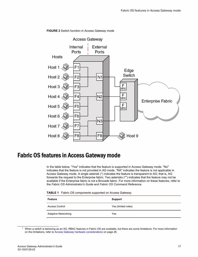
FIGURE 2 Switch function in Access Gateway mode
Fabric OS features in Access Gateway modeIn the table below, "Yes" indicates that the feature is supported in Access Gateway mode. "No"indicates that the feature is not provided in AG mode. "NA" indicates the feature is not applicable inAccess Gateway mode. A single asterisk (*) indicates the feature is transparent to AG; that is, AGforwards the request to the Enterprise fabric. Two asterisks (**) indicates that the feature may not beavailable if the Enterprise fabric is not a Brocade fabric. For more information on these features, refer tothe Fabric OS Administrator's Guide and Fabric OS Command Reference.
Fabric OS components supported on Access Gateway TABLE 1
Feature Support
Access Control Yes (limited roles)
Adaptive Networking Yes
1 When a switch is behaving as an AG, RBAC features in Fabric OS are available, but there are some limitations. For more informationon the limitations, refer to Access Gateway hardware considerations on page 26.
Fabric OS features in Access Gateway mode
Access Gateway Administrator's Guide 1753-1003126-02

Fabric OS components supported on Access Gateway (Continued)TABLE 1
Feature Support
Admin Domains No
Audit Yes
Beaconing Yes
Bottleneck Detection Yes
Buffer Credit Recovery (CR) Yes -
Refer to Buffer credit recovery support on page 20 .
Config Download/Upload Yes
Device Authentication Yes
Refer to Device authentication support on page 21.
DHCP Yes
Diagnostic Port (D_Port) Yes
Refer to D_Port support on page 48.
Duplicate PWWN handling during device login Yes
Refer to Duplicate PWWN handling during device login onpage 84.
Encryption Configuration and Management No
Environmental Monitor Yes
Error Event Management Yes
Extended Fabrics No
Fabric Assigned PWWN (FA-PWWN) Yes
Fabric Device Management Interface (FDMI) Yes*
Fabric Manager Yes**
Fabric Provisioning No
Fabric Services No
Fabric Watch Yes
Refer to the Fabric Watch Administrator's Guide forapplicable support details.
Fibre Channel Routing (FCR) services No
Access Gateway Basic Concepts
18 Access Gateway Administrator's Guide53-1003126-02

Fabric OS components supported on Access Gateway (Continued)TABLE 1
Feature Support
FICON (includes CUP) No
Forward Error Correction (FEC) Yes
Refer to Forward error correction support on page 20.
High Availability Yes
Hot Code Load Yes
License Yes**
Lightweight Directory Access Protocol (LDAP) Yes
Log Tracking Yes
Management Server NA
Manufacturing Diagnostics Yes
N_Port ID Virtualization (NPIV) Yes
Name Server NA
Native Interoperability Mode NA
Network Time Protocol (NTP) No (no relevance from fabric perspective)
Open E_Port NA
Performance Monitor Yes
Persistent ALPA Yes
Port Decommission No
Port Mirroring No
QuickLoop, QuickLoop Fabric Assist No
Remote Authentication Dial-In User Service (RADIUS) Yes
Resource Monitor Yes
Security Yes (ADS/DCC Policy)
SNMP Yes
Speed Negotiation Yes
2 In embedded switches, time should be updated by the server management utility.
Access Gateway Basic Concepts
Access Gateway Administrator's Guide 1953-1003126-02

Fabric OS components supported on Access Gateway (Continued)TABLE 1
Feature Support
Syslog Daemon Yes
Track Changes Yes
Trunking Yes**
User-Defined Roles Yes
Value Line Options (Static POD, DPOD) Yes
Virtual Fabrics No
Refer to Virtual Fabrics support on page 21 .
Web Tools Yes
Zoning NA
Buffer credit recovery supportThis Fabric OS feature is supported on 8 Gbps and 16 Gbps platforms in the following configurations:
• Between AG switch F_Port and Brocade HBA port using Adapter v3.2 or greater firmware or anydevice supporting credit recovery, This feature only works at the maximum supported speed of theHBA port (8 Gbps or 16 Gbps).
• Between AG switch N_Port and Brocade fabric switch or cascaded AG switch F_Port.
It is highly recommended that you disable this feature on the AG switch before connecting to a switchrunning Fabric OS earlier than 7.1. Enable and disable credit recovery using theportcfgcreditrecovery command. Refer to the Fabric OS Command Reference for more informationon this command.
Specific switch platforms support this feature either in R_RDY or VC_RDY mode. In VC_RDY mode,the buffer credit recovery is supported with fabric assigned PWWN (FA-PWWN), FEC, QoS, andtrunking Fabric OS features. In R_RDY mode, this feature is supported without FA-PWWN and QoSFabric OS features.
Forward error correction supportForward error correction (FEC) is a Fabric OS feature supported in the following configurations:
• Between the AG switch F_Port and a Brocade 16 Gbps HBA port running version 3.2 or greaterfirmware.
• Between the AG switch N_Port and F_Port on Brocade 16 Gbps fabric switch or cascaded AGswitch.
Following are limitations and considerations for FEC:
• Supported on Brocade 16 Gbps platforms only.• Supported by Fabric OS 7.1.0 and later.• Enabled by default.
Buffer credit recovery support
20 Access Gateway Administrator's Guide53-1003126-02

• A Fabric OS downgrade requires FEC to be disabled.• Specific switch platforms support this feature either in R_RDY or VC_RDY mode.
Virtual Fabrics supportAlthough you cannot enable AG mode on a switch enabled for Virtual Fabrics or enable Virtual Fabricson an AG switch, you can connect ports on an AG switch to Virtual Fabrics.
Device authentication supportDevices use authentication as a mechanism to log in into switches only after exchanging DH_CHAPauthorization keys. This prevents any unauthorized device from logging into switch and fabric bydefault.
Authentication policy is supported in the following configurations for Access Gateway switches.Regardless of the enabled policy, the AG port disables if the DH-CHAP or FCAP fails to authenticateeach other.
• Access Gateway switch N_Port connected to Brocade fabric switch F_Port. The N_Port shouldenable authentication when authentication is enabled on the connected switch. This can be done byenabling switch policy on the AG switch and device policy on the fabric switch.
• Access Gateway switch F_Port connected to an HBA. The F_Port also should enable authenticationwhen the connected device is sending login request with authentication enabled. This is done byenabling device policy on the AG switch.
By default, Brocade switches use DH-CHAP or FCAP authentication protocols. For authenticationbetween fabric switches and AG switches, FCAP and DH-CHAP are used. If an FCAP certificate ispresent on the AG switch and fabric switch, FCAP has precedence over DHCAP. For authenticationbetween AG switches and HBAs, DH-CHAP is used because the HBA only supports DH-CHAP.
For details on installing FCAP certificates and creating DHCAP secrets on the switch in AG or nativemode, refer to the Fabric OS Administrator’s Guide or Fabric OS Command Reference.
For general information on authentication, refer to the section on authentication policy for fabricelements in the "Configuring Security Policies" chapter of the Fabric OS Administrator’s Guide.
Supported policy modes
The following switch and device policy modes are supported by Access Gateway:
• On - Strict authentication will be enforced on all ports. The ports on the AG connected to the switchor device will disable if the connecting switch or device does not support authentication or the policymode is set to off. During AG initialization, authentication initiates on all ports automatically.
• Off - The AG switch does not support authentication and rejects any authentication negotiationrequest from the connected fabric switch or HBA. A fabric switch with the policy mode set to offshould not be connected to an AG switch with policy mode set to on since the on policy is strict. Thiswill disable the port if any switch rejects the authentication. You must configure DH-CHAP sharedsecrets or install FCAP certificates on the AG and connected fabric switch before switching from apolicy "off" mode to policy "on" mode. Off is the default mode for both switch and device policy.
• Passive - The AG does not initiate authentication when connected to a device, but participates inauthentication if the connecting device initiates authentication. The AG will not initiate authenticationon ports, but accepts incoming authentication requests. Authentication will not disable AG F_Ports ifthe connecting device does not support authentication or the policy mode is set to off. Passive modeis the safest mode to use for devices connected to an AG switch if the devices do not supportauthentication.
Virtual Fabrics support
Access Gateway Administrator's Guide 2153-1003126-02
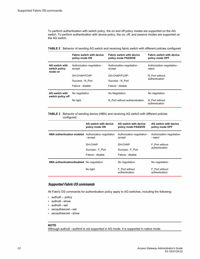
To perform authentication with switch policy, the on and off policy modes are supported on the AGswitch. To perform authentication with device policy, the on, off, and passive modes are supported onthe AG switch.
Behavior of sending AG switch and receiving fabric switch with different policies configuredTABLE 2
Fabric switch with devicepolicy mode ON
Fabric switch with devicepolicy mode PASSIVE
Fabric switch with devicepolicy mode OFF
AG switch withswitch policymode on
Authorization negotiation -accept
DH-CHAP/FCAP:
Success - N_Port
Failure - disable
Authorization negotiation -accept
DH-CHAP/FCAP:
Success - N_Port
Failure - disable
Authorization negotiation -reject
N_Port withoutauthentication
AG switch withswitch policy off
No negotiation
No light
No Negotiation
N_Port without authenctication.
No negotiation
N_Port withoutauthentication
Behavior of sending device (HBA) and receiving AG switch with different policiesconfigured
TABLE 3
AG switch with devicepolicy mode ON
AG switch with devicepolicy mode PASSIVE
AG switch with devicepolicy mode OFF
HBA authentication enabled Authorization negotiation- accept
DH-CHAP
Success - F_Port
Failure - disable
Authorization negotiation -accept
DH-CHAP
Success - F_Port
Failure - disable
Authorization negotiation- reject
F_Port withoutauthentication
HBA authenticationdisabled No negotiation
No light
No negotiation
F_Port withoutauthentication
No negotiation
F_Port withoutauthentication
Supported Fabric OS commands
All Fabric OS commands for authentication policy apply to AG switches, including the following:
• authutil -- policy• authutil --show• authutil --set• secauthsecret --set• secauthsecret --show
NOTEAlthough authutil --authinit is not supported in AG mode, it is supported in native mode.
Supported Fabric OS commands
22 Access Gateway Administrator's Guide53-1003126-02

For more information, refer to the Fabric OS Command Reference .
Limitations and considerations
• Authentication policy is not supported on cascaded AG switch configurations.• Authentication is not supported between an AG switch running Fabric OS v7.1.0 or later and a fabric
running Fabric OS earlier than v7.1.0. If the AG switch is connected to fabric switch running FabricOS earlier than v7.1.0, the AG switch N_Ports will disable if authentication is enabled on bothswitches. Devices mapped to N_Ports connected to fabrics operating with Fabric OS before v7.1.0will also disable.
• If authentication is disabled on the Fabric Switch, the AG switch N_Port will come online withoutauthentication policy.
• Device and switch policies must be disabled on the AG before converting the switch to Native mode.• Device and switch policies must be disabled on the switch in Native mode before converting it to AG
mode.• Authentication policy is disabled by default on all ports in AG mode.• High availability (HA) reboots are supported.
AG mode without all POD licensesPrior to Fabric OS 7.3.0, the Brocade non-embedded switches (Brocade 300, 5100, 6505, and 6510)require all POD licenses to run in Access Gateway mode. However, starting with Fabric OS release7.3.0, all POD licenses are not required to run these switches in AG mode.
The following points need to be considered while running the switches in AG mode without all PODlicenses:
• By default, configured N_Ports will come up as disabled because a POD license is not installed forthose ports.
• All F_Ports mapped to the default N-port will come up as disabled with the following reason N-PortOffline for F-Port
• You must manually configure N_Ports in the switch using the portcfgnport command, and move thecable connections accordingly.
• You can update the N_Port-to-F_Port mapping using the mapdel and mapadd commands.• You must install all POD licenses to downgrade from Fabric OS 7.3.0 to any previous release.
Password distribution supportPrior to Fabric OS 7.3.0, user account and password database can only be managed locally on theswitches in AG mode. You had to either manually populate the password database in the AG mode orchange the switch to native mode and then back to AG mode to populate the password database.Starting with Fabric OS 7.3.0, running the distribute command on any of the switches in native mode,will distribute the password database to all AGs and switches connected to the same fabric. You candistribute using the AG name or use *.* to distribute to all switches and AGs.
Consider the following points regarding password distribution:
• The fddCfg command in the AG can only be used to configure to either accept or reject thepassword database coming from any of the switches in the same fabric.
• To accept the password database from any switch, the AG must be loaded with Fabric OS 7.3.0, andat least one of the switches in native mode within the same fabric must be loaded with Fabric OS7.3.0.
• Other databases supported by fddCfg are not supported on AGs.
Limitations and considerations
Access Gateway Administrator's Guide 2353-1003126-02

• VF mode distribution is not applicable to an AG.• The distribute command is not supported in AG mode. Hence, an AG cannot distribute its
password database to any of the switches in native mode.
FDMI supportStarting with Fabric OS 7.3.0, AG can register its N_Port with FDMI devices, and the fdmishowcommand is supported to display the device details in AG as well. The fdmishow command in an AGwill display only the local devices, and the remote device details are blocked.
Access Gateway port typesAccess Gateway differs from a typical fabric switch because it is not a switch; instead, it is a mode thatyou enable on a switch using the ag command. After a switch is set in Access Gateway mode, it canconnect to the fabric using node ports (N_Ports). Typically, fabric switches connect to the Enterprisefabric using interswitch link (ISL) ports, such as E_Ports.
AG uses the following Fibre Channel (FC) ports:
• F_Port - Fabric port that connects a host, HBA, or storage device to a switch in AG mode.• N_Port - Node port that connects a switch in AG mode to the F_Port of the fabric switch.• D_Port - Port configured in diagnostic mode so that various tests can run between it and connected
D_Port on another switch or HBA across a link.
NOTEInitiate the portcfgpersisentenable command on all external or outward facing ports to ensure thatthese ports come back online after a switch reboot or power failure. For an embedded switch, executethis command through the chassis management console and not the switch CLI or the command maynot persist. Refer to Persisting port online state on page 47 for more information.
Comparison of Access Gateway ports to standard switch portsAccess Gateway multiplexes host connections to the fabric. It presents an F_Port to the host and anN_Port to an Edge fabric switch. Using N_Port ID Virtualization (NPIV), AG allows multiple FCinitiators to access the SAN on the same physical port. This reduces the hardware requirements andmanagement overhead of hosts to the SAN connections.
A fabric switch presents F_Ports (or FL_Ports) and storage devices to the host and presents E_Ports,VE_Ports, or EX_Ports to other switches in the fabric. A fabric switch consumes SAN resources, suchas domain IDs, and participates in fabric management and zoning distribution. A fabric switch requiresmore physical ports than AG to connect the same number of hosts.
The figure below shows a comparison of the types of ports a switch in AG mode uses to the type ofports that a switch uses in standard mode.
FDMI support
24 Access Gateway Administrator's Guide53-1003126-02

FIGURE 3 Port usage comparison
You can convert a Fibre Channel port into a D_Port on AG switch and a connected fabric switch,another AG switch (cascaded configuration), or an HBA to test the link between the ports. When youconfigure the ports on each end of the link as D_Ports, diagnostic tests automatically initiate on the linkwhen the D_Ports go online. Results can be viewed using Fabric OS commands, such asportDPortTest, during or after testing. Once in D_Port mode, the port does not participate in fabricoperations, login to a remote device, or run data traffic.
Access Gateway Basic Concepts
Access Gateway Administrator's Guide 2553-1003126-02

FIGURE 4 Diagnostic port configurations
The table below shows a comparison of port configurations between AG and a standard fabric switch.
Port configurationsTABLE 4
Port type Available on Access Gateway? Available on Fabric switch?
F_Port Yes Connects hosts and targets to AccessGateway.
Yes Connects devices, such as hosts, HBAs, andstorage to the fabric.
N_Port Yes Connects Access Gateway to a fabricswitch.
N/A N_Ports are not supported.
E_Port N/A ISL is not supported. Yes Connects the switch to other switches toform a fabric.
D_Port Yes Allows diagnostic testing across link toconnected AG switch, fabric switch, orHBA.
Yes Allows diagnostic testing across link toconnected AG switch.
Access Gateway hardware considerationsHardware considerations for Access Gateway are as follows:
• Access Gateway is supported on the switch platforms and embedded switch platforms listed in Supported hardware and software on page 11.
• Loop devices are not supported.• Direct connections to SAN target devices are only supported if the AG-enabled module is
connected to a fabric.
3 The switch is logically transparent to the fabric, therefore it does not participate in the SAN as a fabric switch.
Access Gateway hardware considerations
26 Access Gateway Administrator's Guide53-1003126-02

Configuring Ports in Access Gateway Mode
● Enabling and disabling Access Gateway mode.............................................................. 27● Access Gateway mapping...............................................................................................29● N_Port configurations......................................................................................................46● D_Port support................................................................................................................ 48
Enabling and disabling Access Gateway mode
Use the following steps to enable and disable Access Gateway mode. After you enable AG mode, somefabric information is erased, such as the zone and security databases. Enabling AG mode is disruptivebecause the switch is disabled and rebooted. For more information on the ag commands used in thesesteps, refer to the Fabric OS Command Reference.
1. Connect to the switch and log in using an account assigned to the admin role.2. Before enabling or disabling a switch to AG mode, save the current configuration file using the
configUpload command in case you might need this configuration again.3. Ensure that no zoning or Admin Domain (AD) transaction buffers are active. If any transaction buffer
is active, enabling AG mode will fail with the error, "Failed to clear Zoning/Admin Domainconfiguration".
4. Verify that the switch is set to Native mode.a) Issue the switchShow command to verify the switch mode.b) If the switch mode is anything other than 0, issue the interopmode 0 command to set the
switch to Native mode.
For more information on setting switches to Native mode, refer to the Fabric OSAdministrator’s Guide.
5. Enter the switchDisable command.
switch:admin> switchdisableThis command disables all user ports on a switch. All Fibre Channel ports are taken offline. If theswitch is part of a fabric, the remaining switches reconfigure. You must disable the switch beforemaking configuration changes.
6. Enter the ag - -modeenable command.
switch:admin> ag --modeenableThe switch automatically reboots and comes back online in AG mode using a factory default portmapping. For more information on AG default port mapping, refer to Table 7 on page 31.
7. Enter the ag --modeshow command to verify that AG mode is enabled.
switch:admin> ag --modeshowAccess Gateway mode is enabled.You can display the port mappings and status of the host connections to the fabric on AccessGateway.
8. Enter the ag --mapshow command to display all the mapped ports.
The ag --mapshow command shows all enabled N_Ports, even if those N_Ports are not connected.
Access Gateway Administrator's Guide 2753-1003126-02

9. Enter the switchShow command to display the status and port state of all ports. Refer to the FabricOS Command Reference for examples of output. For a description of the port state, refer to Table 5on page 28.
When you disable AG mode, the switch automatically reboots and comes back online using thefabric switch configuration; the AG parameters, such as port mapping, and Failover and Failback,are automatically removed. When the switch reboots, it starts in Fabric OS Native mode. To rejointhe switch to the core fabric, refer to Rejoining Fabric OS switches to a fabric on page 95.
10.Enter the switchDisable command to disable the switch.
switch:admin> switchdisable11.Enter the ag command with the --modedisable option to disable AG mode.
switch:admin> ag --modedisable12.Enter the ag --modeshow command to verify that AG mode is disabled.
switch:admin> ag --modeshowAccess Gateway mode is NOT enabled
Port state descriptionRefer to the following table to know the port state.
Port state description TABLE 5
State Description
No _Card No interface card present
No _Module No module (GBIC or other) present
Mod_Val Module validation in process
Mod_Inv Invalid module
No_Light Module is not receiving light
No_Sync Receiving light but out of sync
In_Sync Receiving light and in sync
Laser_Flt Module is signaling a laser fault
Port_Flt Port marked faulty
Diag_Flt Port failed diagnostics
Lock_Ref Locking to the reference signal
Testing Running diagnostics
Offline Connection not established (only for virtual ports)
Online Port is up and running
Port state description
28 Access Gateway Administrator's Guide53-1003126-02

Access Gateway mappingWhen operating in AG mode, you must specify pre-provisioned routes that AG will use to direct trafficfrom the devices (hosts or targets) on its F_Ports to the ports connected to the fabric using its N_Ports.This is unlike Native switch mode where the switch itself determines the best path between its F_Ports.This process of pre-provisioning routes in AG mode is called "mapping."
During mapping, device World Wide Names (WWNs) or F_Ports are assigned to N_Ports and N_Portgroups on the switch running in AG mode. Mapping ensures that a device logging in to the switch willalways connect to the fabric through a specific N_Port or N_Port group. Two types of mapping areavailable:
• Port mapping
A specific F_Port is mapped to a specific N_Port. This ensures that all traffic from a specific F_Portalways goes through the same N_Port. To map an F_Port to an N_Port group, simply map the port toan N_Port that belongs to that port group. All F_Ports mapped to that N_Port will be part of thatN_Port group.
• Device mapping (optional)
A specific device WWN is mapped to N_Port groups (preferred method) or to specific N_Ports.Device mapping allows a virtual port to access its destination device regardless of the F_Port wherethe device resides. Device mapping also allows multiple virtual ports on a single physical machine toaccess multiple destinations residing in different fabrics.
Device mapping is optional and should be added on top of existing port maps. Port mapping mustexist at all times.
Port mappingF_Ports must be mapped to N_Ports before the F_Ports can come online. The figure below shows anexample in which eight F_Ports are mapped evenly to four N_Ports on a switch in AG mode. TheN_Ports connect to the same fabric through different Edge switches.
Access Gateway mapping
Access Gateway Administrator's Guide 2953-1003126-02

FIGURE 5 Port mapping example
The following table describes the port mapping details for the above example.
Description of port mapping TABLE 6
Access Gateway Fabric
F_Port N_Port Edge switch F_Port
F_1, F_2 N_1 Switch_A F_A1
F_3, F_4 N_2 Switch_A F_A2
F_5, F_6 N_3 Switch_B F_B1
F_7, F_8 N_4 Switch_B F_B2
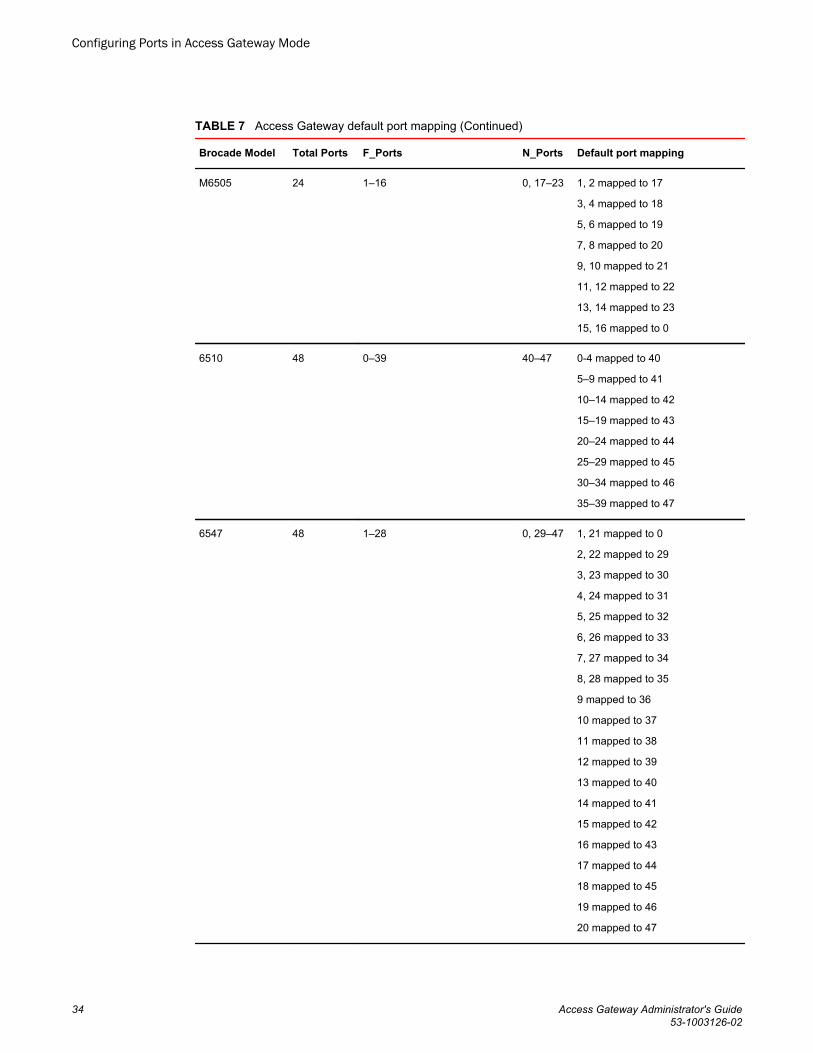
Default port mapping
When you first enable a switch for AG mode, the F_Ports are mapped to a set of predefined N_Portsby default. The table below describes the default port mapping for all supported hardware platforms.By default, Failover and Failback policies are enabled on all N_Ports.
If you want to change the default mapping, refer to Adding F_Ports to an N_Port on page 35. Notethat all F_Ports must be mapped to an N_Port before the F_Port can come online.
Default port mapping
30 Access Gateway Administrator's Guide53-1003126-02

NOTEPrior to Fabric OS 7.3.0, all POD licenses must be present to use the Brocade 300, 5100, 6505, and6510 as an Access Gateway. However, Fabric OS 7.3.0 does not require all POD licenses to run in AGmode.
Access Gateway default port mappingTABLE 7
Brocade Model Total Ports F_Ports N_Ports Default port mapping
VA-40FC 40 0–31 32–39 0–3 mapped to 32
4–7 mapped to 33
8–11 mapped to 34
12–15 mapped to 35
16–19 mapped to 36
20–23 mapped to 37
24–27 mapped to 38
28–31 mapped to 39
300 24 0–15 16–23 0, 1 mapped to 16
2, 3 mapped to 17
4, 5 mapped to 18
6, 7 mapped to 19
8, 9 mapped to 20
10, 11 mapped to 21
12, 13 mapped to 22
14, 15 mapped to 23
5100 40 0–31 32–39 0, 1, 2, 3 mapped to 32
4, 5, 6, 7 mapped to 33
8, 9, 10, 11 mapped to 34
12, 13, 14, 15 mapped to 35
16, 17, 18, 19 mapped to 36
20, 21, 22, 23 mapped to 37
24, 25, 26, 27 mapped to 28
28, 29, 30, 31 mapped to 39
Configuring Ports in Access Gateway Mode
Access Gateway Administrator's Guide 3153-1003126-02

Access Gateway default port mapping (Continued)TABLE 7
Brocade Model Total Ports F_Ports N_Ports Default port mapping
M5424 24 1–16 0, 17–23 1, 2 mapped to 17
3, 4 mapped to 18
5, 6 mapped to 19
7, 8 mapped to 20
9, 10 mapped to 21
11, 12 mapped to 22
13, 14 mapped to 23
15, 16 mapped to 0
5430 16 1–10 0, 11–15 10 mapped to 0
1, 5 mapped to 11
2, 6 mapped to 12
3, 7 mapped to 13
4, 8 mapped to 14
9 mapped to 15
5431 16 4–15 0–3 4, 5, 12 mapped to 0
6, 7, 13 mapped to 1
8, 9, 14 mapped to 2
10, 11, 15 mapped to 3
5432 24 0, 9–23 1–8 9, 17 mapped to 1
10, 18 mapped to 2
11, 19 mapped to 3
12, 20 mapped to 4
13, 21 mapped to 5
14, 22 mapped to 6
15, 23 mapped to 7
16, 0 mapped to 8
5450 26 1–25
Not all ports may be present.
0, 19–25 1, 2, 17 mapped to 19
3, 4, 18 mapped to 20
5, 6 mapped to 21
7, 8 mapped to 22
9, 10 mapped to 23
11, 12 mapped to 24
13, 14 mapped to 25
15, 16 mapped to 0
Configuring Ports in Access Gateway Mode
32 Access Gateway Administrator's Guide53-1003126-02

Access Gateway default port mapping (Continued)TABLE 7
Brocade Model Total Ports F_Ports N_Ports Default port mapping
5460 26 6–25 0–5 6, 16 mapped to 0
7, 17 mapped to 1
8, 12, 18, and 22 mapped to 2
9, 13, 19, and 23 mapped to 3
10, 14, 20, and 24 mapped to 4
11, 15, 21, and 25 mapped to 5
5470 20 1–14 0, 15–19 1, 2 mapped to 0
3, 4 mapped to 15
5, 6, 7 mapped to 16
8, 9 mapped to 17
10, 11 mapped to 18
12, 13, 14 mapped to 19
5480 24 1–16 0, 17–23 1, 2 mapped to 17
9, 10 mapped to 18
3, 4 mapped to 19
11, 12 mapped to 20
15, 16 mapped to 0
5, 6 mapped to 21
13, 14 mapped to 22
7, 8 mapped to 23
6505 24 1–15 16–23 0, 1 mapped to 16
2, 3 mapped to 17
4, 5 mapped to 18
6, 7 mapped to 19
8, 9 mapped to 20
10, 11 mapped to 21
12, 13 mapped to 22
14, 15 mapped to 23
Configuring Ports in Access Gateway Mode
Access Gateway Administrator's Guide 3353-1003126-02
Access Gateway default port mapping (Continued)TABLE 7
Brocade Model Total Ports F_Ports N_Ports Default port mapping
M6505 24 1–16 0, 17–23 1, 2 mapped to 17
3, 4 mapped to 18
5, 6 mapped to 19
7, 8 mapped to 20
9, 10 mapped to 21
11, 12 mapped to 22
13, 14 mapped to 23
15, 16 mapped to 0
6510 48 0–39 40–47 0-4 mapped to 40
5–9 mapped to 41
10–14 mapped to 42
15–19 mapped to 43
20–24 mapped to 44
25–29 mapped to 45
30–34 mapped to 46
35–39 mapped to 47
6547 48 1–28 0, 29–47 1, 21 mapped to 0
2, 22 mapped to 29
3, 23 mapped to 30
4, 24 mapped to 31
5, 25 mapped to 32
6, 26 mapped to 33
7, 27 mapped to 34
8, 28 mapped to 35
9 mapped to 36
10 mapped to 37
11 mapped to 38
12 mapped to 39
13 mapped to 40
14 mapped to 41
15 mapped to 42
16 mapped to 43
17 mapped to 44
18 mapped to 45
19 mapped to 46
20 mapped to 47
Configuring Ports in Access Gateway Mode
34 Access Gateway Administrator's Guide53-1003126-02

Access Gateway default port mapping (Continued)TABLE 7
Brocade Model Total Ports F_Ports N_Ports Default port mapping
6548 28 1–16 0, 17–27 1, 13 mapped to 0
2, 14 mapped to 17
3, 15 mapped to 18
4, 16 mapped to 19
5 mapped to 20
6 mapped to 21
7 mapped to 22
8 mapped to 23
9 mapped to 24
10 mapped to 25
11 mapped to 26
12 mapped to 27
Considerations for initiator and target ports
The following connections are possible for the Fibre Channel Protocol (FCP) initiator (host) and targetports through AG:
• All F_Ports connect to all initiator ports.• All F_Ports connect to all target ports.• Some F_Ports connect to initiator ports and some F_Ports connect to target ports.
For the last case, communication between initiator and target ports is not supported if both are mappedto the same N_Port. Therefore, follow these recommendations for initiator and target port mapping:
• If connecting a host and target port to the same AG, you should map them to separate N_Ports andconnect those N_Ports to the same fabric.
• Use separate port groups for initiator and target ports.• When configuring secondary port mapping for failover and failback situations, make sure that initiator
and target F_Ports will not fail over or fail back to the same N_Port.
Adding F_Ports to an N_Port
You can modify the default port mapping by adding F_Ports to an N_Port. Adding an F_Port to anN_Port routes that traffic to and from the fabric through the specified N_Port.
You can assign an F_Port to only one primary N_Port at a time. If the F_Port is already assigned to anN_Port, you must first remove it from the N_Port before you can add it to a different N_Port.
Use the following steps to add an F_Port to an N_Port.
1. Connect to the switch and log in using an account assigned to the admin role.2. Enter the ag command with the --mapadd n_portnumber f_port1;f_port2;... option to add the list of
F_Ports to the N_Port.
Considerations for initiator and target ports
Access Gateway Administrator's Guide 3553-1003126-02

The F_Port list can contain multiple F_Port numbers separated by semicolons. In the followingexample, F_Ports 6 and 7 are mapped to N_Port 13.
switch:admin> ag --mapadd 13 "6;7"F-Port to N-Port mapping has been updated successfully
3. Enter the ag --mapshow command and specify the port number to display the list of mappedF_Ports. Verify that the added F_Ports appear in the list.
Removing F_Ports from an N_Port
1. Connect to the switch and log in using an account assigned to the admin role.2. Remove any preferred secondary N_Port settings for the F_Port. Refer to Deleting F_Ports from a
preferred secondary N_Port on page 69 for instructions.3. Enter the ag --mapdel N_Port command with the f_port1;f_port;... option to remove F_Ports from
an N_Port.
The F_Port list can contain multiple F_Port numbers separated by semicolons. In the followingexample, F_Ports 17 and 18 are removed from the N_Port where they were mapped.
switch:admin> ag --mapdel 17;18F-Port to N-Port mapping has been updated successfully
4. Enter the switchShow command to verify that the F_Port is free (unassigned).
In output for this command, the unassigned F_Port status "Disabled (No mapping for F_Port)." willdisplay under the "Proto" column.
F_Port Static MappingThe F_Port Static Mapping feature allows you to change mapping of an F_Port to a different N_Portusing a single Fabric OS command (staticadd or staticdel ), rather than using the ag --mapdelcommand to delete the existing N_Port port mapping to an F_Port, and then the ag --mapaddcommand to map a different N_Port to the F_Port. Using two commands can be slow and can causesome time-critical applications to malfunction.
Use the following steps to change F_Port to N_Port mapping.
1. Connect to the switch and log in using an account assigned to the admin role.2. Enter the following command:
ag --staticadd "N-Port" "F-Port(s)"Once F_Port Static Mapping is enabled, the F_Port and all attached devices log out of thepreviously mapped N_Port and log in to the new N_Port.
Use the following steps to remove the static mapping:
1. Connect to the switch and log in using an account assigned to the adminrole.
2. Perform one of the following steps to remove mapping:
• Map the F_Port to a different N_Port using the ag --staticadd• Enter the following command to remove F_Port mapping entirely:
ag --staticdel “N-Port” “F-Port(s)”
Removing F_Ports from an N_Port
36 Access Gateway Administrator's Guide53-1003126-02
Considerations for using F_Port Static Mapping with other AG features and policies
Consider the following when using F_Port Static Mapping with Access Gateway features and policies:
• F_Port Static Mapping functions with cascaded Access Gateway configurations.• Failover, failback, and preferred secondary N_Port settings are disabled for F_Ports that are statically
mapped.• Statically mapped ports are blocked from using the Automatic Port Configuration (APC) and
Advanced Device Security (ADS) policies. You cannot enable the APC policy until all static mappingsare deleted using the ag --staticdel command.
• F_Port Static Mapping works with the Port Grouping (PG) policy with some modifications to policybehavior. If static mapping is applied to an F_Port already mapped to an N_Port, the F_Port will loseits mapping to the N_Port applied through the Port Grouping policy. Therefore, the F_Port will nothave the failover, failback, or preferred N_Port settings that other F_Ports have when mapped to anN_Port in that port group. To remap to an N_Port with PG policy attributes, use the ag --staticdelcommand to remove the static mapping, and then remap to another N_Port using the ag --mapaddcommand.
• F_Port Static Mapping will not work with Device Load Balancing. Because F_Port Static Mappingforces the F_Port to stick with a specific N_Port, NPIV devices that log in to the F_Port cannotredistribute themselves among N_Ports in the port group.
• F_Port Static Mapping will not work with port trunking. If an F_Port is statically mapped to an N_Portand trunking is enabled, the F_Port goes offline. If port trunking is enabled for an F_Port already, youwill be blocked from configuring static mapping for the F_Port.
Upgrade and downgrade considerations
• All static mappings will be maintained when upgrading to the latest Fabric OS version.• When downgrading, you must remove all static mappings or downgrade will not be allowed.
Device mappingDevice mapping allows you to map individual N_Port ID Virtualization (NPIV) devices to N_Ports. Bymapping device WWNs directly to an N_Port group (recommended) or specific N_Ports, traffic from thedevice will always go to the same N_Port or N_Port group, regardless of the F_Port where the devicelogs in. When the Port Grouping and Device Load Balancing policies are enabled for a port group,WWNs mapped to that port group are automatically balanced among the online N_Ports in that group(refer to Port Grouping policy modes on page 59).
NOTEPort Grouping policy is not supported when both Automatic Login Balancing and Device Load Balancingare enabled.
Device mapping does not affect or replace the traditional port mapping. Device mapping is an optionalmapping that will exist on top of existing port mapping. In general, mapping devices to N_Port groups isrecommended over mapping devices to individual N_Ports within a port group. This ensures maximumdevice "up-time," especially during failover conditions and system power up. This is especially truewhen a reasonably large number of devices must connect to the same fabric through a single portgroup.
The following aspects of device mapping are important to note:
Considerations for using F_Port Static Mapping with other AG features and policies
Access Gateway Administrator's Guide 3753-1003126-02

• Logins from a device mapped to a specific N_Port or N_Port group (device mapping) always havepriority over unmapped devices that log in to an F_Port that has been mapped to the same N_Portor N_Port group (port mapping).
• Current device routing (dynamic mapping) may turn out different than your intended mapping (staticmapping), depending on which N_Ports are online and which policies are enabled (for example,Automatic Port Configuration, Device Load Balancing, Failover, or Failback). Therefore, it isrecommended to map devices to N_Port groups instead of specific N_Ports within a port groupwhen using device mapping.
NOTEAutomatic Port Configuration and Device Load Balancing cannot be enabled at the same time.
The figure below illustrates an example of device mapping to port groups. In the example, WWNs 1, 2,and 3 can connect to any N_Port in Port Group 1 (PG1), while WWNs 4 and 5 can connect with anyN_Port in Port Group 2 (PG2).
Configuring Ports in Access Gateway Mode
38 Access Gateway Administrator's Guide53-1003126-02

FIGURE 6 Example of device mapping to N_Port groups
The figure below shows an example of device mapping to specific N_Ports. Note that you can map oneor multiple WWNs to one N_Port to allow multiple devices to log in through one N_Port.
Configuring Ports in Access Gateway Mode
Access Gateway Administrator's Guide 3953-1003126-02
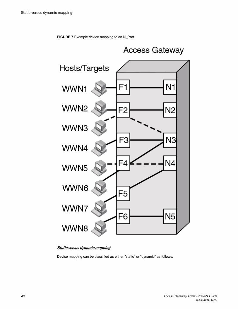
FIGURE 7 Example device mapping to an N_Port
Static versus dynamic mapping
Device mapping can be classified as either "static" or "dynamic" as follows:
Static versus dynamic mapping
40 Access Gateway Administrator's Guide53-1003126-02
• Device mapping to an N_Port and to an N_Port group are considered static. Static mappings persistsacross reboots and can be saved and restored with Fabric OS configUpload and configDownloadcommands.
• Automatic Device Load Balancing, if enabled, is considered dynamic. These mappings exist onlywhile a device is logged in. Dynamic mappings cannot be saved or edited by the administrator anddo not persist across reboots. Dynamic mapping shows the current mapping for devices as opposedto the original static mapping. If a device is mapped to an N_Port group, then all mapping is dynamic.
NOTEStatic and dynamic mapping only applies to NPIV devices and cannot redirect devices that are directlyattached to Access Gateway because physically-attached devices use the port maps to connect to thefabric.
Device mapping to port groups (recommended)
Mapping NPIV devices to a port group is an ideal choice when a reasonably sized set of devices mustconnect to the same group of N_Ports, and you want the flexibility of moving the devices to anyavailable F_Port. This type of mapping is recommended because the device will automatically connectto the least-loaded N_Port in the group if the N_Port to which the device is currently connected goesoffline or is not yet online. For more information on port groups, refer to Port Grouping policy on page56.
Use the following steps to map one or more devices to an N_Port group or remove device mappingfrom an N_Port group.
1. Connect to the switch and log in using an account assigned to the admin role.2. To add one or multiple device WWNs to an N_Port group , enter the ag --addwwnpgmapping
Port_Group command with the [WWN];[WWN] option.
All the listed device WWNs will use the least-loaded N_Port in the port group when they log in, unlessa specific device mapping can be used instead. This command can only map devices currentlyconnecting through NPIV.
The following example adds two devices to port group 3.
ag --addwwnpgmapping 3 "10:00:00:06:2b:0f:71:0c;10:00:00:05:1e:5e:2c:11"3. To change all currently existing device mappings to a different port group, use the -- all option
instead of listing all the WWNs.
The following example changes all the currently mapped devices to use port group 3 instead of thecurrent port group mappings.
ag --addwwnpgmapping 3 --all4. To remove one or multiple devices to an N_Port group , enter the ag --delwwnpgmapping
Port_Group command with the [WWN];[WWN] option.
All the listed devices will stop using the least-loaded N_Port in the group when they log in.
The following example removes mapping for two devices from port group 3.
ag --delwwnpgmapping 3 "10:00:00:06:2b:0f:71:0c;10:00:00:05:1e:5e:2c:11"5. To remove all devices mapped to an N_Port group, enter the command with the --all option instead
of listing all WWNs. All of the devices will cease automatic use of the least-loaded port in the portgroup when they log in. The --all option is a shortcut for specifying all of the devices that are alreadymapped with the addwwnpgmapping command.
Device mapping to port groups (recommended)
Access Gateway Administrator's Guide 4153-1003126-02

The following example removes all devices mapped to port group 3.
ag --delwwnpgmapping 3 --all6. Enter the ag --wwnmapshow command to display the list of WWNs mapped to port groups and
verify that the correct devices have been mapped to the desired port group.
Device mapping to N_Ports
Use the following steps to add one or more devices to an N_Port to route all device traffic to and fromthe device through the specified N_Port. Also use these steps to remove device mapping to anN_Port.
1. Connect to the switch and log in using an account assigned to the admin role.2. To add one or multiple devices to an N_Port , enter the ag --addwwnmapping N_Port command
with the [WWN];[WWN] option. All the listed device WWNs will use the N_Port if it is available.
The following example adds two devices to N_Port 17.
ag --addwwnmapping 17 "10:00:00:06:2b:0f:71:0c;10:00:00:05:1e:5e:2c:11"The --all option edits all the currently existing mappings. None of the --all options have any way todetect what devices are using the switch. This option edits the mappings that are in the list.
3. To change all current device mappings to a different N_Port, enter the ag --addwwnmappingN_Port command with the --all option.
The following command changes all the existing device mappings to use port 17.
ag --addwwnmapping 17 --all4. To remove mapping for one or multiple devices from an N_Port, enter the ag --delwwnmapping
N_Port command with the [WWN];[WWN] option. All the listed device WWNs will no longer try touse the N_Port unless a device logs in through an F_Port that is mapped to the N_Port.
The following example removes two devices from N_Port 17.
ag --delwwnmapping 17 "10:00:00:06:2b:0f:71:0c;10:00:00:05:1e:5e:2c:11"5. To remove all devices currently mapped from an N_Port, enter the ag --delwwnmapping N_Port
command with the --all option. All the listed devices will no longer try to use the N_Port unless adevice logs in through an F_Port that is mapped to the N_Port. The --all option is a shortcut forspecifying all of the devices that are already mapped with the addwwnmapping command.
The following command removes all devices currently mapped to port 17.
ag --delwwnmapping 17 --all6. Enter the ag --wwnmapshow command to display the list of N_Ports mapped to WWNs and verify
that the correct WWNs have been mapped or removed from the desired N_Ports.
Disabling device mapping
Use the following procedures to disable device mapping for all or only specific devices. Theseprocedures are useful when you want to temporarily disable device mapping, and then enable this at alater time without reconfiguring your original mapping.
1. Connect to the switch and log in using an account assigned to the admin role.2. Enter the ag --wwnmappingdisable command with the [WWN]; [WWN] option to disable mapping
for specific WWNs. The device mappings will be ignored for all the listed device WWNs withoutremoving the entry from the WWN mapping database.
Device mapping to N_Ports
42 Access Gateway Administrator's Guide53-1003126-02
The following example disables device mapping for two WWNs.
switch:admin> ag --wwnmappingdisable "10:00:00:06:2b:0f:71:0c; 10:00:00:05:1e:5e:2c:11"
3. Enter the ag--wwnmappingdisable command with the --all option to disable mapping for allavailable WWNs. The --all option will not affect mappings made in the future. Disabled mappings canbe modified without automatically enabling them.
The following example removes device mapping for all available WWNs.
switch:admin> ag --wwnmappingdisable --all
Enabling device mapping
Use the following steps to enable device mapping for all or specific devices that were previouslydisabled.
1. Connect to the switch and log in using an account assigned to the admin role.2. Enter the ag --wwnmappingenable command with the [WWN]; [WWN] option to enable mapping for
specific WWNs.
The following example enables two device WWNs.
switch:admin> ag --wwnmappingenable "10:00:00:06:2b:0f:71:0c; 10:00:00:05:1e:5e:2c:11"
3. Enter the ag --wwnmappingenable command with the --all option to enable mapping for all currentlyavailable WWNs. The --all option will not affect mappings made in the future. Any mapping added fora new device (a device for which mapping is not disabled) will be enabled by default. Disabledmappings can be modified without automatically enabling them.
The following command enables all previously disabled device mappings.
switch:admin> ag --wwnmappingenable --all
Displaying device mapping information
The ag --wwnmapshow command displays static and dynamic mapping information about all deviceWWNs that have been mapped to N_Ports or N_Port groups. For each WWN, this command displaysthe following:
• WWN - Device WWNs that are mapped to N_Ports• 1st N_Port - First or primary mapped N_Port (optional)• 2nd N_Port - Secondary or failover N_Port (optional)• PG_ID - Port Group ID where the device is mapped• Current - The N_Port that the device is using (none displays if the device is not logged in)• Enabled - Indicates whether device mapping is enabled or disabled
Note that new device mappings will only be enabled and display the next time the device logs in to theswitch.
To display device mapping information, enter the ag -- wwnmapshow command.
Pre-provisioning
You can use Fabric OS commands, Web Tools, and Fabric Manager to map devices that do not yetexist. This allows applicable management programs to push configuration changes without worryingabout the order in which they are received. For example, if system administrators need to push a set ofport group changes and a set of device mapping changes, they could push them in either order without
Enabling device mapping
Access Gateway Administrator's Guide 4353-1003126-02

error. This also applies to using Fabric OS commands for device mapping. You could also mapseveral devices to a new port group and then create the group without error. You can also remove onedevice, and then remove another device without error.
VMware configuration considerations
Enabling device mapping for individual virtual machines (VMs) running on a VMware ESX serverconnected to an F_Port can redirect I/O traffic for these VMs, provided the server is configured to useRaw Device Mapped storage. All traffic will originate from a VM’s WWN and will follow any mappingconfigured for the WWN. If anything interrupts the virtual port’s connection for the VM, such as afailover port being used because a port goes offline, traffic will originate from the ESX server’s basedevice port ID and not the VM’s port ID. If there are any additional disruptions, the server will notswitch back to the virtual port, and the VM’s traffic will not follow the configured device mapping. Notethat this can also occur when a VM first boots, prior to any failover.
When this behavior occurs, the VM’s WWN will be properly logged in to the fabric. The WWN appearsin the output of ag --show and ag --wwnmapshow , as well as on the switch. The output from theportperfshow command displays all traffic on the port to which the ESX server port is mapped (basePID).
Configuring device mapping
To configure WWN mapping on VMware ESX systems, use the following steps.
1. Make sure that virtual world wide port names (VWWPN) of virtual machines (VMs) are mapped tothe correct port group (or N_Port). Map all VWWPNs to N_Ports to avoid confusion.
2. Make sure all VWWPNs are mapped for LUN access for array-based targets.3. Make sure to include all VWWPNs in the zone configuration.4. Reboot the VM.5. Zone the server’s physical port to the storage device.6. Check the traffic that originates from the virtual node PID (VN PID). If the configuration is correct,
traffic will flow from the VN PID.
For additional information on using device mapping for connecting VMware systems, refer to theTechnical Brief How to Configure NPIV on VMware ESX Server 3.5 :
http://www.brocade.com/downloads/documents/brocade_vmware_technical_briefs/Brocade_NPIV_ESX3.5_WP.pdf.
Failover and failback considerations
When using device mapping with VMware, the base device initiates PLOGI and PRLI to the target,and then discovers the LUN. The virtual device also initiates a PLOGI and PRLI to the target, but LUNdiscovery does not occur. Therefore, when the device-mapped port is toggled and failover or failbacktakes place, traffic will resume from the base device. One of the following actions is recommendedwhen using device mapping with VMware:
• Make sure targets can be reached by the base device so that I/Os can resume if the mapped devicefails over and I/Os move over to the base PID.
• Reboot the server so that it initializes and uses configured device mapping.
Considerations for Access Gateway mappingThis section outlines considerations and limitations for Access Gateway mapping types.
VMware configuration considerations
44 Access Gateway Administrator's Guide53-1003126-02

Mapping priority
To avoid potential problems when both port and device mapping are implemented, AG uses thefollowing priority system when verifying policies to select the N_Port where a fabric login (FLOGI) isrouted. Access Gateway considers all available mappings in the following order until one can be used.
NOTEOnly NPIV devices can use device mapping and the automatic Device Load Balancing policy. DeviceLoad Balancing policy is enabled per module rather than per port group.
For more information, refer to Port Grouping policy on page 56.
1. Static device mapping to N_Port (if defined)2. Device mapping to N_Port group (if defined)3. Automatic Device Load Balancing within a port group (if enabled)4. Port mapping to an N_Port5. Port mapping to an N_Port in a port group (if defined)
Device mapping considerations
Consider the following points when using device mapping:
• If the N_Port is disabled, all devices that are mapped to it will be disabled. Depending on theeffective failover policy, the devices will be enabled on other N_Ports.
• Similar to port mappings, device mappings are affected by changes to underlying F_Ports. In otherwords, if an F_Port needs to be taken offline, both the physical device and all virtual nodes behind itwill momentarily go offline.
• Once devices are mapped to an N_Port rather than an N_Port group, they cannot be automaticallyrebalanced to another N_Port if an additional N_Port comes online.
• There can be cases where two NPIV devices logging in through the same F_Port are mapped to twodifferent N_Ports that are connected to two different fabrics. In this case, both NPIV devices may beallocated the same PID by their respective fabrics. Once Access Gateway detects this condition, itwill disable that F_Port, and the event will be logged.
NOTEAccess Gateway algorithms reduce the chances of PID collisions, but they cannot be totally eliminated.In some cases, you may be able to configure your virtual or physical fabrics to further reduce PIDcollisions.
• Device mapping is not supported when firmware is downgraded to Fabric OS v6.3.x or earlier. Youmust delete device mappings before downgrading or disable Device Load Balancing.
• Static and dynamic device mapping are only supported on the edge module in a cascaded AccessGateway configuration.
• When mapping devices to a port group, make sure that all ports in the group have the same NPIVlogin limit. If some ports have a lower login limit than the other ports, and there are many logins to thegroup, some devices will repeatedly attempt to connect to the device with the lower limit (because ithas the fewest logins) and fail to connect.
Mapping priority
Access Gateway Administrator's Guide 4553-1003126-02
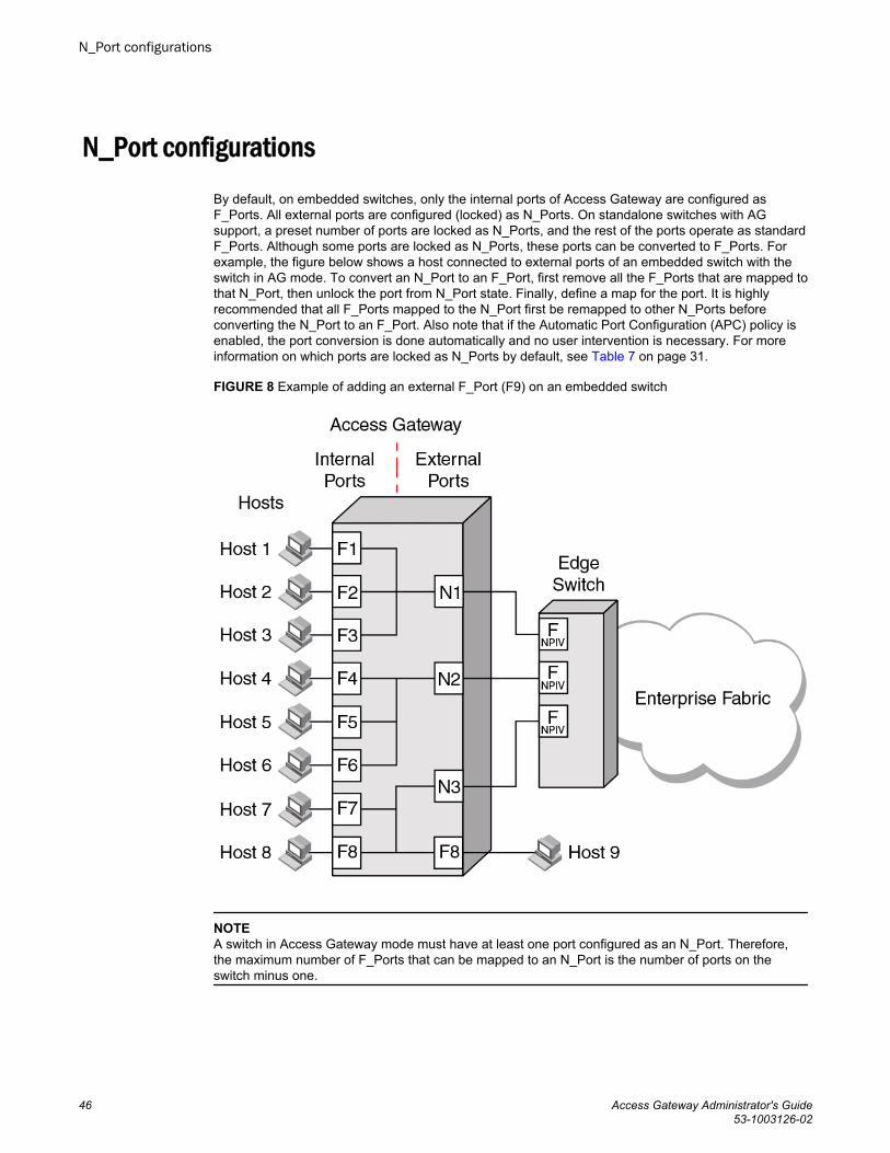
N_Port configurationsBy default, on embedded switches, only the internal ports of Access Gateway are configured asF_Ports. All external ports are configured (locked) as N_Ports. On standalone switches with AGsupport, a preset number of ports are locked as N_Ports, and the rest of the ports operate as standardF_Ports. Although some ports are locked as N_Ports, these ports can be converted to F_Ports. Forexample, the figure below shows a host connected to external ports of an embedded switch with theswitch in AG mode. To convert an N_Port to an F_Port, first remove all the F_Ports that are mapped tothat N_Port, then unlock the port from N_Port state. Finally, define a map for the port. It is highlyrecommended that all F_Ports mapped to the N_Port first be remapped to other N_Ports beforeconverting the N_Port to an F_Port. Also note that if the Automatic Port Configuration (APC) policy isenabled, the port conversion is done automatically and no user intervention is necessary. For moreinformation on which ports are locked as N_Ports by default, see Table 7 on page 31.
FIGURE 8 Example of adding an external F_Port (F9) on an embedded switch
NOTEA switch in Access Gateway mode must have at least one port configured as an N_Port. Therefore,the maximum number of F_Ports that can be mapped to an N_Port is the number of ports on theswitch minus one.
N_Port configurations
46 Access Gateway Administrator's Guide53-1003126-02
Displaying N_Port configurationsUse the following steps to determine which ports on a switch are locked as N_Ports.
1. Connect to the switch and log in using an account assigned to the admin role.2. Enter the portcfgnport command. Command output will display "ON" for locked N_Ports.
Unlocking N_PortsBy default, on embedded switches, all external ports are configured in N_Port lock mode when youenable Access Gateway. Access Gateway connects only FCP initiators and targets to the fabric. It doesnot support other types of ports, such as ISL (interswitch link) ports.
By default, on fabric switches, the port types are not locked. Fabric OS Native mode dynamicallyassigns the port type based on the connected device: F_Ports and FL_Ports for hosts, HBAs, andstorage devices; and E_Ports, EX_Ports, and VE_Ports for connections to other switches.
Unlocking the N_Port configuration automatically changes the port to an F_Port. When you unlock anN_Port, the F_Ports are automatically unmapped and disabled.
Following are procedures for unlocking N_Ports that are in locked mode.
1. Connect to the switch and log in using an account assigned to the admin role.2. Enter the portcfgnport command to display which ports on the switch are locked as N_Ports.
Command output will display "ON" for locked N_Ports.
NOTEThe portcfgnport command only works when the Port Grouping policy is enabled.
3. Enter the portcfgnport command and specify the port number and 0 (zero) to unlock N_Port mode.
switch:admin> portcfgnport 10 0Alternatively, to lock a port in N_Port mode, enter the portcfgnport and specify the port number and1 .
switch:admin> portcfgnport 10 1
Persisting port online stateInitiate the portcfgpersisentenable command on all external or outward facing ports to ensure thatthese ports come back online after a switch reboot or power failure. For an embedded switch, executethis command through the chassis management console and not the switch CLI or the command maynot persist.
If the port is connected to another switch when this command is issued, the fabric may reconfigure.After the port is persistently enabled, devices connected to the port can again communicate with thefabric. Identify a single port to be configured by its port number or by its port index number. Port rangesare supported with index numbers or by specifying a slot or a slot range. Issue the switchShowcommand for a list of valid ports, slots, and port index numbers.
As an example, to persistently enable a port or range of ports, enter the following:
portcfgpersistentenable [slot/]port1[-port2] [...]
Displaying N_Port configurations
Access Gateway Administrator's Guide 4753-1003126-02

D_Port supportThe Diagnostic (D_Port) feature is supported on 16-Gbps ports in the following configurations:
• An AG switch connected to an AG switch in cascaded configuration (supports only static D_Port).• An AG switch connected to a Brocade fabric switch (supports only static D_Port).• An AG switch connected to a Brocade HBA (supports static D_Port starting with Fabric OS 7.2.0;
dynamic D_Port starting with Fabric OS 7.3.0 and HBA v3.2.0).
The following types of D_Ports are supported:
• Static D_Port -- You can convert a Fibre Channel port into a D_Port on an AG switch, BrocadeHBA, fabric switch, or another AG switch (cascaded configuration) to test the link between the ports.When you configure the ports on each end of the link as a D_Port, diagnostic tests automaticallyinitiate on the link when the D_Ports go online. Once in D_Port mode, the port does not participatein fabric operations, log in to a remote device, or run data traffic. Comparison of Access Gatewayports to standard switch ports on page 24 illustrates the supported D_Port configurations.
• Dynamic D_Port-- An AG switch supports dynamic D_Port mode starting with Fabric OS 7.3.0. Ifthe port on the connected Brocade HBA v3.2.0 is configured as a static D_Port, the AG portautomatically goes into D_Port mode. Once the AG port goes into dynamic D_Port mode, the switchruns all the diagnostic tests automatically from the AG switch to connected HBA. Once the tests arecomplete, the AG port will automatically revert back to an F_Port mode, if the HBA or device portreverts back to be a normal port. However, dynamic D_Port mode is not supported in AG-to-AG andAG-to-Switch connections; you need to configure and remove the D_Port statically in these cases.
To enable dynamic D_Port support on the AG switch, you can use the following switch-wideconfiguration option available in the configure command:Dynamic D-Port (on, off): [on] onBy default, the dynamic D_Port is on (enabled).
NOTEN_Port-to-F_Port mappings must be removed from an AG F_Port before configuring it as a D_Port.Refer to Saving port mappings on page 49.
Results from D_Port testing can be viewed using Fabric OS commands, such as portDPortTest --show, during or after testing. The adapter, fabric switch, or AG switch will be the initiator and the otherwill be the responder. You can view detailed results from the initiator.
The following tests automatically run on the link between configured D_Ports:
• Electrical loopback in SFP• Optical loopback in SFP• Link traffic test to test frame flow to ASIC or CPU• Link latency and distance measurement
For details on configuring D_Ports, using D_Ports, and D_Port limitations and considerations, refer tothe Fabric OS Administrator's Guide. For details on D_Port-related commands, refer to the Fabric OSCommand Reference.
Limitations and considerationsFollowing are specific limitations and considerations for using D_Ports in AG switch configurations. Fora complete list of D_Port limitations and considerations, refer to the Fabric OS Administrator's Guide.
D_Port support
48 Access Gateway Administrator's Guide53-1003126-02
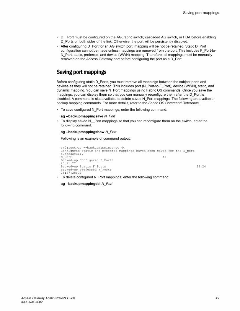
• D__Port must be configured on the AG, fabric switch, cascaded AG switch, or HBA before enablingD_Ports on both sides of the link. Otherwise, the port will be persistently disabled.
• After configuring D_Port for an AG switch port, mapping will be not be retained. Static D_Portconfiguration cannot be made unless mappings are removed from the port. This includes F_Port-to-N_Port, static, preferred, and device (WWN) mapping. Therefore, all mappings must be manuallyremoved on the Access Gateway port before configuring the port as a D_Port.
Saving port mappingsBefore configuring static D_Ports, you must remove all mappings between the subject ports anddevices as they will not be retained. This includes port (N_Port-to-F_Port), device (WWN), static, anddynamic mapping. You can save N_Port mappings using Fabric OS commands. Once you save themappings, you can display them so that you can manually reconfigure them after the D_Port isdisabled. A command is also available to delete saved N_Port mappings. The following are availablebackup mapping commands. For more details, refer to the Fabric OS Command Reference .
• To save configured N_Port mappings, enter the following command:
ag --backupmappingsave N_Port• To display saved N__Port mappings so that you can reconfigure them on the switch, enter the
following command:
ag --backupmappingshow N_Port
Following is an example of command output:
sw0:root>ag --backupmappingshow 44Configured static and prefered mappings haved been saved for the N_port successfullyN_Port 44Backed-up Configured F_Ports 20:21:22Backed-up Static F_Ports 23:24Backed-up Preferred F_Ports 26:27:28:29
• To delete configured N_Port mappings, enter the following command:
ag --backupmappingdel N_Port
Saving port mappings
Access Gateway Administrator's Guide 4953-1003126-02

Saving port mappings
50 Access Gateway Administrator's Guide53-1003126-02
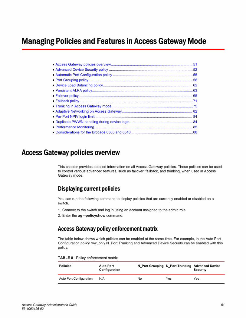
Managing Policies and Features in Access Gateway Mode
● Access Gateway policies overview................................................................................. 51● Advanced Device Security policy ................................................................................... 52● Automatic Port Configuration policy ............................................................................... 55● Port Grouping policy........................................................................................................56● Device Load Balancing policy......................................................................................... 62● Persistent ALPA policy....................................................................................................63● Failover policy................................................................................................................. 65● Failback policy.................................................................................................................71● Trunking in Access Gateway mode.................................................................................75● Adaptive Networking on Access Gateway...................................................................... 82● Per-Port NPIV login limit................................................................................................. 84● Duplicate PWWN handling during device login...............................................................84● Performance Monitoring..................................................................................................85● Considerations for the Brocade 6505 and 6510..............................................................88
Access Gateway policies overviewThis chapter provides detailed information on all Access Gateway policies. These policies can be usedto control various advanced features, such as failover, failback, and trunking, when used in AccessGateway mode.
Displaying current policiesYou can run the following command to display policies that are currently enabled or disabled on aswitch.
1. Connect to the switch and log in using an account assigned to the admin role.2. Enter the ag --policyshow command.
Access Gateway policy enforcement matrixThe table below shows which policies can be enabled at the same time. For example, in the Auto PortConfiguration policy row, only N_Port Trunking and Advanced Device Security can be enabled with thispolicy.
Policy enforcement matrixTABLE 8
Policies Auto PortConfiguration
N_Port Grouping N_Port Trunking Advanced DeviceSecurity
Auto Port Configuration N/A No Yes Yes
Access Gateway Administrator's Guide 5153-1003126-02

Policy enforcement matrix (Continued)TABLE 8
Policies Auto PortConfiguration
N_Port Grouping N_Port Trunking Advanced DeviceSecurity
N_Port Grouping Mutually exclusive N/A Yes Yes
N_Port Trunking Yes Yes N/A Yes
Advanced Device Security Yes Yes Yes N/A
Device Load Balancing No Yes Yes Yes
Advanced Device Security policyAdvanced Device Security (ADS) is a security policy that restricts access to the fabric at the AG levelto a set of authorized devices. Unauthorized access is rejected and the system logs a RASLOGmessage. You can configure the list of allowed devices for each F_Port by specifying their Port WWN(PWWN). The ADS policy secures virtual and physical connections to the SAN.
How the ADS policy worksWhen you enable the ADS policy, it applies to all F_Ports on the AG-enabled module. By default, alldevices have access to the fabric on all ports. You can restrict the fabric connectivity to a particular setof devices where AG maintains a per-port allow list for the set of devices whose PWWN you define tolog in through an F_Port. You can view the devices with active connections to an F_Port using the ag--show command.
NOTEThe ag --show command only displays F_Ports on Core AGs, such as the AGs that are directlyconnected to fabric. Use the agshow --name command on the fabric switch to display the F_Ports ofboth the Core and Edge AGs.
Alternatively, the security policy can be established in the Enterprise fabric using the DeviceConnection Control (DCC) policy. For information on configuring the DCC policy, refer to Enabling theDCC policy on a trunk on page 77. The DCC policy in the Enterprise fabric takes precedence overthe ADS policy. It is generally recommended to implement the security policy in the AG module ratherthan in the main fabric, especially if the Failover and Failback policies are enabled.
Enabling and disabling the ADS policyBy default, the ADS policy is disabled. When you manually disable the ADS policy, all of the allow lists(global and per-port) are cleared. Before disabling the ADS policy, you should save the configurationusing the configUpload command in case you need this configuration again.
4 The ADS policy is not supported when using device mapping.5 Device Load Balancing and Automatic Login Balancing cannot be enabled for the same port group.
Advanced Device Security policy
52 Access Gateway Administrator's Guide53-1003126-02

1. Connect to the switch and log in using an account assigned to the admin role.2. Enter the ag --policyenable ads command to enable the ADS policy.
switch:admin> ag --policyenable adsThe policy ADS is enabled
3. Enter the ag - - policydisable ads command to disable the ADS policy.
switch:admin> ag --policydisable adsThe policy ADS is disabled
NOTEUse the ag --policyshow command to determine the current status of the ADS policy.
Allow listsYou can determine which devices are allowed to log in on a per-F_Port basis by specifying lists ofF_Ports and device WWNs in the ag --adsset command. The ADS policy must be enabled for thiscommand to succeed.
ag --adsset "F_Port [ ;F_Port2;... ] " " WWN [ ;WWN2;... ]"
Lists must be enclosed in quotation marks. List members must be separated by semicolons. Themaximum number of entries in the allowed device list is twice the per-port maximum login count.
Use an asterisk (*) instead of port numbers in the F_Port list to add the specified WWNs to all theF_Ports allow lists. Use an asterisk (*) instead of WWNs to indicate access to all devices from thespecified F_Port list. A blank WWN list ("") indicates no access.
NOTEUse an asterisk enclosed in quotation marks ("*") to set the allow list to "all access"; use a pair of doublequotation marks ("") to set the allow list to "no access".
Note the following characteristics of the allow list:
• The maximum device entries allowed in the allow list is twice the per-port maximum login count.• Each port can be configured to "not allow any device" or "to allow all the devices" to log in.• If the ADS policy is enabled, by default, every port is configured to allow all devices to log in.• The same allow list can be specified for more than one F_Port.
Setting the list of devices allowed to log in
1. Connect to the switch and log in using an account assigned to the admin role.2. Enter the ag --adsset command with the appropriate options to set the list of devices allowed to log
in to specific ports. In the following example, ports 1, 10, and, 13 are set to "all access."
switch:admin> ag --adsset "1;10;13" "*"WWN list set successfully as the Allow Lists of the F_Port[s]
Allow lists
Access Gateway Administrator's Guide 5353-1003126-02

Setting the list of devices not allowed to log in
1. Connect to the switch and log in using an account assigned to the admin role.2. Enter the ag --adsset command with the appropriate options to set the list of devices not allowed to
log in to specific ports. In the following example, ports 11 and 12 are set to "no access."
switch:admin > ag --adsset "11;12" ""WWN list set successfully as the Allow Lists of the F_Port[s]
Removing devices from the list of allowed devices
Remove specified WWNs from the list of devices allowed to log in to the specified F_Ports using theag --adsdel command.
ag--adsdel " F_Port [; F_Port2; ...] " " WWN [ ;WWN2;.. .] "
For more details on this command and its operands, refer to the Fabric OS Command ReferenceManual .
Lists must be enclosed in quotation marks. List members must be separated by semicolons. Replacethe F_Port list with an asterisk (*) to remove the specified WWNs from all the F_Ports allow lists. TheADS policy must be enabled for this command to succeed.
1. Connect to the switch and log in using an account assigned to the admin role.2. Enter the ag--adsdel command to remove one or more devices from the list of allowed devices.
In the following example, two devices are removed from the list of allowed devices (ports 3 and 9).
switch:admin> ag --adsdel "3;9" "22:03:08:00:88:35:a0:12;22:00:00:e0:8b:88:01:8b"WWNs removed successfully from Allow Lists of the F_Port[s]Viewing F_Ports allowed to login
Adding new devices to the list of allowed devices
Add specified WWNs to the list of devices allowed to log in to the specified F_Ports using the ag --adsadd command.
ag--adsadd " F_Port [;F_Port2;...] " " WWN [;WWN2;...] "
For more details on this command and its operands, refer to the Fabric OS Command ReferenceManual .
Lists must be enclosed in quotation marks. List members must be separated by semicolons. Replacethe F_Port list with an asterisk (*) to add the specified WWNs to all the F_Ports allow lists. The ADSpolicy must be enabled for this command to succeed.
1. Connect to the switch and log in using an account assigned to the admin role.2. Enter the ag --adsadd command with the appropriate options to add one or more new devices to
the list of allowed devices.
In the following example, two devices are added to the list of allowed devices (for ports 3 and 9).
switch:admin> ag --adsadd "3;9" "20:03:08:00:88:35:a0:12;21:00:00:e0:8b:88:01:8b"WWNs added successfully to Allow Lists of the F_Port[s]
Setting the list of devices not allowed to log in
54 Access Gateway Administrator's Guide53-1003126-02

Displaying the list of allowed devices on the switch
1. Connect to the switch and log in using an account assigned to the admin role.2. Enter the ag --adsshow command.
For each F_Port, command output will show access for all devices, a list of device WWNs, or noaccess. For more details on this command and its output, refer to the Fabric OS CommandReference Manual .
ADS policy considerationsThe following are considerations for setting the ADS policy:
• In cascading configurations, you should set the ADS policy on the AG module that directly connectsto the servers.
• The ADS policy can be enabled or disabled independent of the status of other AG policies.• The ADS policy is not supported with device mapping.
Upgrade and downgrade considerations for the ADS policyDowngrading to Fabric OS v6.4.0 or earlier is supported.
Downgrading from Fabric OS v7.1.0 to v6.4.0 or upgrading from Fabric OS v6.4.0 to v7.1.0 will notchange the ADS policy settings.
Automatic Port Configuration policyThe Automatic Port Configuration (APC) provides the ability to automatically discover port types (host,target, or fabric) and dynamically update the port maps when a change in port-type connection isdetected. This policy is intended for a fully hands-off operation of Access Gateway. APC dynamicallymaps F_Ports across available N_Ports so they are evenly distributed.
How the APC policy worksWhen the APC policy is enabled and a port on AG is connected to a Fabric switch, AG configures theport as an N_Port. If a host is connected to a port on AG, then AG configures the port as an F_Port andautomatically maps it to an existing N_Port with the least number of F_Ports mapped to it. When theAPC policy is enabled, it applies to all ports on the switch.
Enabling and disabling the APC policyUse the following steps to enable and disable Automatic Port Configuration policy. This policy isdisabled by default in Access Gateway.
Enabling the APC policy
1. Connect to the switch and log in using an account assigned to the admin role.2. Enter the switchDisable command to ensure that the switch is disabled.
Displaying the list of allowed devices on the switch
Access Gateway Administrator's Guide 5553-1003126-02
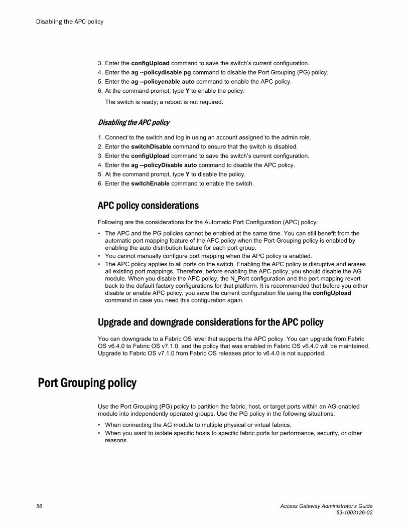
3. Enter the configUpload command to save the switch’s current configuration.4. Enter the ag --policydisable pg command to disable the Port Grouping (PG) policy.5. Enter the ag --policyenable auto command to enable the APC policy.6. At the command prompt, type Y to enable the policy.
The switch is ready; a reboot is not required.
Disabling the APC policy
1. Connect to the switch and log in using an account assigned to the admin role.2. Enter the switchDisable command to ensure that the switch is disabled.3. Enter the configUpload command to save the switch’s current configuration.4. Enter the ag --policyDisable auto command to disable the APC policy.5. At the command prompt, type Y to disable the policy.6. Enter the switchEnable command to enable the switch.
APC policy considerationsFollowing are the considerations for the Automatic Port Configuration (APC) policy:
• The APC and the PG policies cannot be enabled at the same time. You can still benefit from theautomatic port mapping feature of the APC policy when the Port Grouping policy is enabled byenabling the auto distribution feature for each port group.
• You cannot manually configure port mapping when the APC policy is enabled.• The APC policy applies to all ports on the switch. Enabling the APC policy is disruptive and erases
all existing port mappings. Therefore, before enabling the APC policy, you should disable the AGmodule. When you disable the APC policy, the N_Port configuration and the port mapping revertback to the default factory configurations for that platform. It is recommended that before you eitherdisable or enable APC policy, you save the current configuration file using the configUploadcommand in case you need this configuration again.
Upgrade and downgrade considerations for the APC policyYou can downgrade to a Fabric OS level that supports the APC policy. You can upgrade from FabricOS v6.4.0 to Fabric OS v7.1.0, and the policy that was enabled in Fabric OS v6.4.0 will be maintained.Upgrade to Fabric OS v7.1.0 from Fabric OS releases prior to v6.4.0 is not supported.
Port Grouping policyUse the Port Grouping (PG) policy to partition the fabric, host, or target ports within an AG-enabledmodule into independently operated groups. Use the PG policy in the following situations:
• When connecting the AG module to multiple physical or virtual fabrics.• When you want to isolate specific hosts to specific fabric ports for performance, security, or other
reasons.
Disabling the APC policy
56 Access Gateway Administrator's Guide53-1003126-02
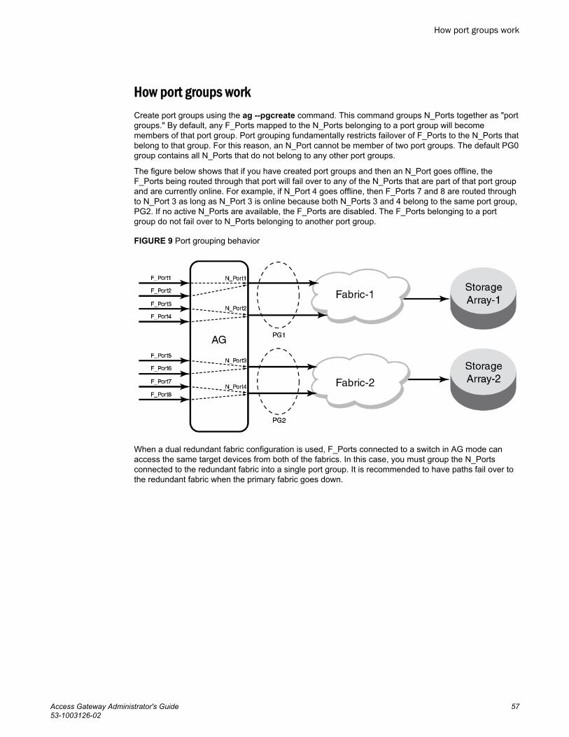
How port groups workCreate port groups using the ag --pgcreate command. This command groups N_Ports together as "portgroups." By default, any F_Ports mapped to the N_Ports belonging to a port group will becomemembers of that port group. Port grouping fundamentally restricts failover of F_Ports to the N_Ports thatbelong to that group. For this reason, an N_Port cannot be member of two port groups. The default PG0group contains all N_Ports that do not belong to any other port groups.
The figure below shows that if you have created port groups and then an N_Port goes offline, theF_Ports being routed through that port will fail over to any of the N_Ports that are part of that port groupand are currently online. For example, if N_Port 4 goes offline, then F_Ports 7 and 8 are routed throughto N_Port 3 as long as N_Port 3 is online because both N_Ports 3 and 4 belong to the same port group,PG2. If no active N_Ports are available, the F_Ports are disabled. The F_Ports belonging to a portgroup do not fail over to N_Ports belonging to another port group.
FIGURE 9 Port grouping behavior
When a dual redundant fabric configuration is used, F_Ports connected to a switch in AG mode canaccess the same target devices from both of the fabrics. In this case, you must group the N_Portsconnected to the redundant fabric into a single port group. It is recommended to have paths fail over tothe redundant fabric when the primary fabric goes down.
How port groups work
Access Gateway Administrator's Guide 5753-1003126-02
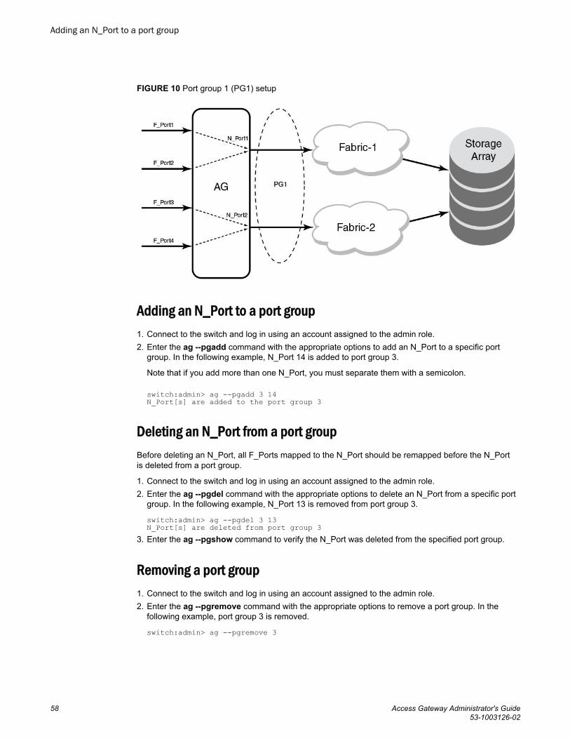
FIGURE 10 Port group 1 (PG1) setup
Adding an N_Port to a port group1. Connect to the switch and log in using an account assigned to the admin role.2. Enter the ag --pgadd command with the appropriate options to add an N_Port to a specific port
group. In the following example, N_Port 14 is added to port group 3.
Note that if you add more than one N_Port, you must separate them with a semicolon.
switch:admin> ag --pgadd 3 14N_Port[s] are added to the port group 3
Deleting an N_Port from a port groupBefore deleting an N_Port, all F_Ports mapped to the N_Port should be remapped before the N_Portis deleted from a port group.
1. Connect to the switch and log in using an account assigned to the admin role.2. Enter the ag --pgdel command with the appropriate options to delete an N_Port from a specific port
group. In the following example, N_Port 13 is removed from port group 3.
switch:admin> ag --pgdel 3 13N_Port[s] are deleted from port group 3
3. Enter the ag --pgshow command to verify the N_Port was deleted from the specified port group.
Removing a port group1. Connect to the switch and log in using an account assigned to the admin role.2. Enter the ag --pgremove command with the appropriate options to remove a port group. In the
following example, port group 3 is removed.
switch:admin> ag --pgremove 3
Adding an N_Port to a port group
58 Access Gateway Administrator's Guide53-1003126-02

Renaming a port group1. Connect to the switch and log in using an account assigned to the admin role.2. Enter the ag --pgrename command with the appropriate options to rename a port group. In the
following example, port group 2 is renamed to MyEvenFabric.
switch:admin> ag --pgrename 2 MyEvenFabricPort Group 2 has been renamed as MyEvenFabric successfully
Disabling the Port Grouping policyThe Port Grouping (PG) policy is enabled by default for Access Gateway. To disable this policy, use thefollowing steps.
1. Connect to the switch and log in using an account assigned to the admin role.2. Enter the ag --policydisable pg command to disable the Port Grouping policy.
Port Grouping policy modesYou can enable and disable the Automatic Login Balancing and Managed Fabric Name Monitoring(MFNM) Port Grouping policy modes when you create port groups using the pgcreate command.Alternately, you can enable these modes using the ag --pgsetmodes command.
Automatic Login Balancing mode
If Automatic Login Balancing mode is enabled for a port group and an F_Port goes offline, logins in theport group are redistributed among the remaining F_Ports. Similarly, if an N_Port comes online, portlogins in the port group are redistributed to maintain a balanced N_Port-to-F_Port ratio.
Consider the following notes about Automatic Login Balancing mode:
• Automatic Login Balancing mode is disruptive. However, you can minimize disruption by disabling orenabling rebalancing of F_Ports on F_Port offline events or N_Port online events.
• You must explicitly enable Automatic Login Balancing on a port group.• If an N_Port is deleted from a port group enabled for Automatic Login Balancing mode, the F_Ports
mapped to that N_Port stay with the port group as long as there are other N_Ports in the group. Onlythe specified N_Port is removed from the port group. This is because the F_Ports are logicallyassociated with the port groups that are enabled for Automatic Login Balancing mode. This is not thecase for port groups not enabled for Automatic Login Balancing mode. When you delete an N_Portfrom one of these port groups, the F_Ports that are mapped to the N_Port move to PG0 along withthe N_Port. This is because the F_Ports are logically associated with the N_Ports in port groups notenabled for Automatic Login Balancing mode.
Managed Fabric Name Monitoring mode
When enabled, Managed Fabric Name Monitoring (MFNM) mode queries the fabric name at a specifictime period. If it detects an inconsistency, for example all the N_Ports within a port group are notphysically connected to the same physical or virtual fabric, it generates a RASLOG message. In"default" mode, a message is logged into RASLOG. In "managed" mode, automatic failover is disabledfor all N_Ports within the N_Port group, and a message is logged into RASLOG about multiple fabrics.
Enable or disable MFNM mode on a port group using the steps under Enabling MFNM mode on page61 and Disabling MFNM mode on page 61. In both default and managed mode, the system queriesthe fabric name once every 120 seconds. You can configure the monitoring timeout value to something
Renaming a port group
Access Gateway Administrator's Guide 5953-1003126-02

other than 120 seconds using the steps under Setting the current MFNM mode timeout value on page61.
Creating a port group and enabling Automatic Login Balancing mode1. Connect to the switch and log in using an account assigned to the admin role.2. Enter the ag --pgcreate command with the appropriate options to create a port group. In the
following example, a port group named "FirstFabric" is created that includes N_Ports 1 and 3 andhas Automatic Login Balancing (lb) enabled.
switch:admin> ag --pgcreate 3 "1;3" -n FirstFabric1 -m "lb"Port Group 3 created successfully
3. Enter the ag --pgshow command to verify the port group was created. A table containing a portgroup with ID 3 and ports 1 and 3 should display.
Rebalancing F_Ports
To minimize disruption that could occur once F_Ports go offline or when additional N_Ports arebrought online, you can modify the default behavior of Automatic Login Balancing mode by disablingor enabling rebalancing of F_Ports when F_Port offline or N_Port online events occur.
1. Connect to the switch and log in using an account assigned to the admin role.2. Enter the agautomapbalance --enable command with the appropriate options to enable automatic
login redistribution of F_Ports. In the following example, rebalancing of F_Ports in port group 1 inAccess Gateway is enabled when an F_Port online event occurs.
switch:admin> agautomapbalance --enable -fport -pg 13. Enter the agautomapbalance --disable - all command with the appropriate options to disable
automatic login distribution of N_Ports for all port groups in the Access Gateway when an N_Portonline event occurs.
switch:admin> agautomapbalance --disable -nport -all4. Enter the agautomapbalance --disable - all command with the appropriate options to disable
automatic login distribution of F_Ports for all port groups in the Access Gateway when an F_Portonline event occurs.
switch:admin> agautomapbalance --disable -fport -all5. Enter the agautomapbalance --show command to display the automatic login redistribution
settings for port groups. In the following example, there are two port groups, 0 and 1.
switch:admin> agautomapbalance --showAG Policy: pg--------------------------------------------PG_ID LB mode nport fport--------------------------------------------0 Enabled Enabled Disabled1 Disabled - -This command also displays the automatic login redistribution settings for N_Ports and F_Ports. Formore details on this command and its output, refer to the Fabric OS Command Reference Manual .
Considerations when disabling Automatic Login Balancing mode
Consider the following when disabling Automatic Login Balancing mode:
Creating a port group and enabling Automatic Login Balancing mode
60 Access Gateway Administrator's Guide53-1003126-02
• Be aware that modifying Automatic Login Balancing mode default settings using theagautomapbalance command may yield uneven distribution of F_Ports to N_Ports. In such cases,you might consider a manual login distribution that forces a rebalancing of F_Ports to N_Ports.
• To control automatic rebalancing to avoid disruptions when the Port Grouping policy is enabled, referto Rebalancing F_Ports on page 60.
Enabling MFNM mode1. Connect to the switch and log in using an account assigned to the admin role.2. Enter the ag --pgsetmodes command with the appropriate options to enable MFNM mode. This
command changes the monitoring mode from "default" to "managed." In the following example,MFNM mode is enabled for port group 3.
switch:admin> ag --pgsetmodes 3 "mfnm"Managed Fabric Name Monitoring mode has been enabled for Port Group 3
Disabling MFNM mode1. Connect to the switch and log in using an account assigned to the admin role.2. Enter the ag --pgdelmodes command with the appropriate options to disable MFNM mode. In the
following example, MFNM mode is disabled for port group 3.
switch:admin> ag --pgdelmodes 3 "mfnm"Managed Fabric Name Monitoring mode has been disabled for Port Group 3
3. Enter the ag --pgshow command to display the port group configuration. If disabled, "mfnm" shouldnot display under PG_Mode for port 3.
For more details on this command and its operands, refer to the Fabric OS Command ReferenceManual .
Displaying the current MFNM mode timeout value1. Connect to the switch and log in using an account assigned to the admin role.2. Enter the ag --pgfnmtov command to display the current MFNM timeout value.
switch:admin> ag --pgfnmtovFabric Name Monitoring TOV: 120 seconds
Setting the current MFNM mode timeout value1. Connect to the switch and log in using an account assigned to the admin role.2. Enter the ag --pgfnmtov command, followed by a value in seconds.
switch:admin> ag --pgfnmtov 100This sets the timeout value to 100 seconds.
Port Grouping policy considerationsFollowing are the considerations for the Port Grouping policy:
• A port cannot be a member of more than one port group.• The PG policy is enabled by default in Fabric OS v6.0 and later. A default port group "0" (PG0) is
created, which contains all ports on the AG.
Enabling MFNM mode
Access Gateway Administrator's Guide 6153-1003126-02

• APC policy and PG policy are mutually exclusive. You cannot enable these policies at the sametime.
• If an N_Port is added to a port group or deleted from a port group and Automatic Login Balancingmode is enabled or disabled for the port group, the N_Port maintains its original failover or failbacksetting. If an N_Port is deleted from a port group, it automatically gets added to port group 0.
• When specifying a preferred secondary N_Port for a port group, the N_Port must be from the samegroup. If you specify an N_Port as a preferred secondary N_Port and it already belongs to anotherport group, the operation fails. Therefore, it is recommended to form groups before defining thepreferred secondary path.
• If the PG policy is disabled while a switch in AG mode is online, all the defined port groups aredeleted, but the port mapping remains unchanged. Before disabling the PG policy, you should savethe configuration using the configUpload command in case you might need this configurationagain.
• If N_Ports connected to unrelated fabrics are grouped together, N_Port failover within a port groupcan cause the F_Ports to connect to a different fabric. The F_Ports may lose connectivity to thetargets to which they were connected before the failover, thus causing I/O disruption, as shown in How port groups work on page 57. Ensure that the port group mode is set to MFNM mode (refer to Enabling MFNM mode on page 61). This monitors the port group to detect connection to multiplefabrics and disables failover of the N-ports in the port group. For more information on MFNM, referto Managed Fabric Name Monitoring mode on page 59.
Upgrade and downgrade considerations for the Port Grouping policyDowngrading to Fabric OS v6.4.0 or earlier is supported.
Note the following considerations when upgrading to Fabric OS 7.1.0:
• When upgrading to Fabric OS v7.1.0 from v6.4.0, the PG policy that was enforced in Fabric OSv6.4.0 continues to be enforced in Fabric OS v7.1.0 and the port groups are retained. You shouldsave the configuration file using the configUpload command in case you might need thisconfiguration again.
• Upgrade to Fabric OS v7.1.0 from Fabric OS prior to v6.4.0 is not supported.
Device Load Balancing policyWhen the Device Load Balancing policy is enabled, devices mapped to a port group always log in tothe least-loaded N_Port in that port group. This helps to distribute the login load on each of theN_Ports. This policy is intended for use in conjunction with device mapping. It provides an automaticapproach to mapping devices to the least-loaded N_Port within an N_Port group. To effectively usethis policy, it is recommended that you map devices to desired N_Port groups before enabling thispolicy. The Port Grouping policy must be enabled before you can enable Device Load Balancing.
Manually created mappings from devices to N_Ports take precedence over automatically createdmappings. Refer to Mapping priority on page 45 for details on connection priority for AG port mapping.For more information on device mapping, refer to Device mapping on page 37.
Enabling the Device Load Balancing policyUse the following steps to enable Device Load Balancing.
1. Connect to the switch and log in using an account assigned to the admin role.2. Enter the configUpload command to save the switch’s current configuration.
Upgrade and downgrade considerations for the Port Grouping policy
62 Access Gateway Administrator's Guide53-1003126-02

3. The Port Grouping policy must be enabled to enable Device Load Balancing. Enter the ag --policyshow command to determine if the Port Grouping policy is enabled. If it is not enabled, enterag --policyenable pg to enable this policy.
4. Enter the ag --policyenable wwnloadbalance command to enable the Device Load Balancingpolicy. Because Fibre Channel devices are identified by their WWNs, CLI commands use deviceWWNs.
Disabling the Device Load Balancing policyBefore disabling this policy, you should save the configuration using the configUpload command incase you need this configuration again.
1. Connect to the switch and log in using an account assigned to the admin role.2. Enter the ag --policydisable wwnloadbalance command to disable the Device Load Balancing
policy.3. Enter the ag --policyshow command to determine the current status of the Device Load Balancing
policy.
Device Load Balancing policy considerations• The Device Load Balancing policy should be enabled on the edge AG of a cascaded AG
configuration.• The Device Load Balancing policy is not applicable on a port group when the APC policy or
Automatic Login Balancing are enabled.• If a device is mapped to a port that is currently part of a trunk, then the device will use that trunk.
When trunking is used with the Device Load Balancing policy, then the load on each trunk will beproportional to the number of ports in that trunk. Use the ag -show command to determine thedevices using a particular trunk.
• When using the Device Load Balancing policy, make sure that all ports in the port group have thesame NPIV login limit. If some ports have a lower login limit than the other ports, and there are manylogins to the group, some devices will repeatedly attempt to connect to the device with the lower limit(because it has the fewest logins) and fail to connect.
Persistent ALPA policyThe Persistent ALPA policy is meant for host systems with operating systems that cannot handledifferent PID addresses across login sessions when booting over a SAN. The Persistent ALPA policy forswitches in Access Gateway mode allows you to configure the AG module so that the host is more likelyto get the same PID when it logs out of and into the same F_Port. Because the Arbitrated Port LoopAddress (ALPA) field makes up a portion of the PID, the PID may change across switch or server powercycles. This policy, if enabled, helps reduce the chances of a different PID being issued for the samehost.
The benefit of this policy is that it ensures that a host has the same ALPA on the F_Ports through thehost power cycle. You can also achieve the same behavior and benefit by setting the same policy in themain (core) fabric. When this policy is enabled, AG will request the same ALPA from the core fabric.However, depending on the fabric, this request may be denied. When this occurs, the host is assigned adifferent ALPA. The following modes deal with this situation:
Disabling the Device Load Balancing policy
Access Gateway Administrator's Guide 6353-1003126-02

• In "Flexible" mode, the AG logs an event that it did not receive the same (requested) ALPA from thecore fabric and brings up the device with the ALPA assigned by the fabric.
• In the "Stringent" mode, if the requested ALPA is not available, the server login will be rejected andthe server port cannot log in to the fabric.
Enabling the Persistent ALPA policyBy default, Persistent ALPA is disabled. You can enable Persistent ALPA using the ag --persistentalpaenable command with the following syntax and with one of the following value types:
ag -persistentalpaenable 1/0[On/Off] -s/-f[Stringent/Flexible]
• Flexible ALPA assigns an unassigned ALPA value when the ALPA assigned to the device is takenby another host.
• Stringent ALPA causes the host login request to be rejected by AG if assignment of the same ALPAis not possible.
To enable Persistent ALPA, use the following steps.
1. Connect to the switch and log in using an account assigned to the admin role.2. Enter the ag --persistentalpaenable command to enable persistent ALPA in flexible (-f ) or
stringent (-s ) mode. The following example shows enabling the policy in flexible mode.
switch:admin> ag --persistentalpaenable 1 -fTo ensure consistency among the different devices, after Persistent ALPA is enabled, all the ALPAsbecome persistent, whether or not they were logged in before the Persistent ALPA policy wasenabled.
Disabling the Persistent ALPA policyWhen you disable this policy, do not specify the value type (for example, flexible ALPA or stringentALPA). Use the following steps.
1. Connect to the switch and log in using an account assigned to the admin role.2. Enter the ag --persistentalpadisable command.
switch:admin> ag --persistentalpaenable 0
Persistent ALPA device dataAccess Gateway uses a table to maintain a list of available and used ALPAs. When the number ofentries in this table is exhausted, the host receives an error message. You can remove some of theentries to make space using the instructions in Removing device data from the database on page64.
Removing device data from the database
Use the following steps to remove device data from the database.
1. Connect to the switch and log in using an account assigned to the admin role.2. Enter the ag --deletepwwnfromdb command.
switch:admin> ag --deletepwwnfromdb PWWN
Enabling the Persistent ALPA policy
64 Access Gateway Administrator's Guide53-1003126-02
In the example, PWWN is the port that you want to remove from the database.
Displaying device data
You can view the ALPA of the host related to any ports you delete from the database.
1. Connect to the switch and log in using an account assigned to the admin role.2. Enter the ag --printalpamap command with the appropriate option to display a database entry for a
specific F_Port. The following example will display an entry for F_Port 2.
switch:admin> ag --printalpamap 2
Clearing ALPA valuesYou can clear the ALPA values for a specific port.
1. Connect to the switch and log in using an account assigned to the admin role.2. Enter the ag --clearalpamap command with the appropriate option to remove the PWW-to-ALPA
mapping for a specific port. In the following example, the mapping for port 2 is cleared from thedatabase.
switch:admin> ag --clearalpamap 2
NOTEAll the device data must be persistent in case of a reboot. During a reboot, the tables will be dumpedto the persistent_NPIV_config file.
Persistent ALPA policy considerationsThe Persistent ALPA policy is not supported in the following situations:
• When AG N_Ports are connected to the shared ports of 48-port Director blades.• Cisco fabrics. Enable Persistent FCID mode on the connecting Cisco switch to achieve the same
functionality.• Persistent ALPA configuration will not change to the default when the configDefault command is
used, but will retain the previous configuration.
Failover policyThe Access Gateway Failover policy ensures maximum uptime for the servers. When a port isconfigured as an N_Port, the Failover policy is enabled by default and is enforced during power-up. TheFailover policy allows hosts and targets to automatically remap to another online N_Port if the primaryN-Port goes offline.
NOTEFor port mapping, the Failover policy must be enabled on an N_Port for failover to occur. For devicemapping, if a device is mapped to an N_Port in a port group, the device will always reconnect to theleast-loaded online N_Port in the group (or secondary N_Port in the group if configured) if the primary
Displaying device data
Access Gateway Administrator's Guide 6553-1003126-02

N_Port goes offline. This occurs regardless of whether the Failover policy is enabled or disabled forthe primary N_Port.
Failover with port mappingThe Failover policy allows F_Ports to automatically remap to an online N_Port if the primary N_Portgoes offline. If multiple N_Ports are available for failover, the Failover policy evenly distributes theF_Ports to available N_Ports belonging to the same N_Port group. If no other N_Port is available,failover does not occur and the F_Ports mapped to the primary N_Port go offline as well.
AG provides an option to specify a secondary failover N_Port for an F_Port.
NOTEIf failover and failback policy are disabled, an F_Port mapped to an N_Port will go offline when theN_Port goes offline and it will go online when the N_Port comes online.
Failover configurations in Access Gateway
The following sequence describes how a failover event occurs:
• An N_Port goes offline.• All F_Ports mapped to that N_Port are temporarily disabled.• If the Failover policy is enabled on an offline N_Port, the F_Ports mapped to it will be distributed
among available online N_Ports. If a secondary N_Port is defined for any of these F_Ports, theseF_Ports will be mapped to those N_Ports. If the Port Grouping policy is enabled, then the F_Portsonly fail over to N_Ports that belong to the same port group as the originally offline N_Port.
Failover example
The following example shows the failover sequence of events in a scenario where two fabric ports gooffline, one after the other. Note that this example assumes that no preferred secondary N_Port is setfor any of the F_Ports.
• First, the Edge switch F_A1 port goes offline, as shown in Example 1 below, causing thecorresponding Access Gateway N_1 port to be disabled.
The ports mapped to N_1 fail over; F_1 fails over to N_2 and F_2 fails over to N_3.
• Next, the F_A2 port goes offline, as shown in Example 2 below, causing the corresponding AccessGateway N_2 port to be disabled.
The ports mapped to N_2 (F_1, F_3, and F_4) fail over to N_3 and N_4. Note that the F_Ports areevenly distributed to the remaining online N_Ports and that the F_2 port did not participate in thefailover event.
Failover with port mapping
66 Access Gateway Administrator's Guide53-1003126-02

FIGURE 11 Failover behavior
Managing Policies and Features in Access Gateway Mode
Access Gateway Administrator's Guide 6753-1003126-02
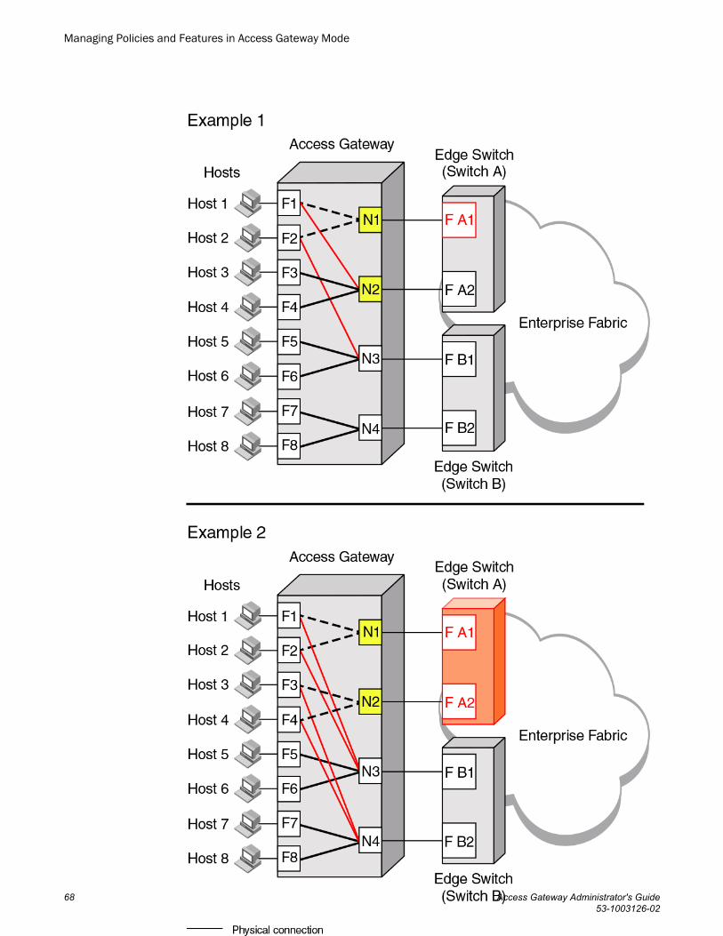
Managing Policies and Features in Access Gateway Mode
68 Access Gateway Administrator's Guide53-1003126-02

Adding a preferred secondary N_Port (optional)
F_Ports automatically fail over to any available N_Port. Alternatively, you can specify a preferredsecondary N_Port in case the primary N_Port fails. If the primary N_Port goes offline, the F_Ports failover to the preferred secondary N_Port (if it is online), then re-enable. If the secondary N_Port is offline,the F_Ports will disable. Define the preferred secondary N_Ports per F_Port. For example, if twoF_Ports are mapped to a primary N_Port, you can define a secondary N_Port for one of those F_Portsand not define a secondary N_Port for the other F_Port. F_Ports must have a primary N_Port mappedbefore a secondary N_Port can be configured.
1. Connect to the switch and log in using an account assigned to the admin role.2. Enter the ag --prefset command with the "F_Port1;F_Port2; ..." N_Port options to add the preferred
secondary F_Ports to the specified N_Port.
The F_Ports must be enclosed in quotation marks and the port numbers must be separated by asemicolon, as shown in the following example.
switch:admin> ag --prefset "3;9" 4Preferred N_Port is set successfully for the F_Port[s]
NOTEPreferred mapping is not allowed when Automatic Login Balancing mode is enabled for a port group.All N_Ports are the same when Automatic Login Balancing mode is enabled.
Deleting F_Ports from a preferred secondary N_Port
1. Connect to the switch and log in using an account assigned to the admin role.2. Enter the ag --prefdel command with the "F_Port1 ;F_Port2 ;... " N_Port options to delete F_Ports
from an N_Port.
The list of F_Ports must be enclosed in quotation marks. Port numbers must be separated by asemicolon. In the following example, F_Ports 3 and 9 are deleted from preferred secondary N_Port 4.
switch:admin> ag --prefdel "3;9" 4Preferred N_Port is deleted successfully for the F_Port[s]
Failover with device mappingFailover is handled similarly for port mapping and device mapping if devices are mapped to N_Portgroups. If a device is mapped to an N_Port in a group, and an N_Port goes offline, the devices mappedto that N_Port will reconnect on the least-loaded online N_Ports in the group.
Enabling or disabling the Failover or Failback policies for N_Ports has no effect on device mapping. Adevice will always fail over to an online N_Port in the port group, regardless of whether the Failbackpolicy is enabled for an N_Port or not. Whereas, with port mapping, if you disable the Failover orFailback policy on an N_Port, the F_Port will not fail over or fail back to other N_Ports.
Failover behavior is different if a device is mapped to a specific N_Port instead of to an N_Port group. Ifmapping a device to a specific N_Port, you can define a secondary N_Port that will be used if theprimary N_Port is offline. To maximize the device uptime, it is recommended to map the device to a portgroup rather than to specific N_Ports.
Adding a preferred secondary N_Port (optional)
Access Gateway Administrator's Guide 6953-1003126-02

Adding a preferred secondary N_Port for device mapping (optional)
Use the following steps to configure a secondary N_Port where devices will connect if their first orprimary N_Port, if defined, is unavailable.
1. Connect to the switch and log in using an account assigned to the admin role.2. To configure an N_Port as a failover port for one or multiple devices mapped to a specific N_Port ,
enter the ag --addwwnfailovermapping N_Port command with the "[WWN];[WWN]" option. All ofthe listed device WWNs will use the listed N_Port if it is available and the first mapped N_Port isunavailable.
The following example configures N_Port 32 as the failover port for two devices already mapped toa primary N_Port.
ag --addwwnfailovermapping 32 "10:00:00:06:2b:0f:71:0c;10:00:00:05:1e:5e:2c:11"To configure N_Port 32 as a failover port for all WWNs mapped to the N_Port, enter the ag --addwwnfailovermapping N_Port command with the --all option.
ag --addwwnfailovermapping 32--all
Deleting a preferred secondary N_Port for device mapping (optional)
Use the following steps to remove a secondary N_Port where devices will connect if their first orprimary N_Port, if defined, is unavailable.
1. Connect to the switch and log in using an account assigned to the admin role.2. To delete an N_Port configured as a failover port for one or multiple devices mapped to a specific
N_Port, enter the ag --delwwnfailovermapping N_Port command with the "[WWN];[WWN]" option.All of the listed devices will stop using the N_Port if the first N_Port mapped to the devices isunavailable unless they log in through F_Ports that are mapped to the N_Port.
The following example removes N_Port 32 as the secondary N_Port for two devices alreadymapped to a primary N_Port.
ag --delwwnfailovermapping 32 "10:00:00:06:2b:0f:71:0c;10:00:00:05:1e:5e:2c:11"To remove an N_Port as a failover port for all devices mapped to the N_Port, enter the ag --delwwnfailovermapping N_Port command with the --all option.
The following command removes N_Port 32 as the secondary N_Port for all available devices.
ag --delwwnfailovermapping 32--all
Enabling and disabling the Failover policy on an N_PortUse the following steps to enable or disable the Failover policy on a specific N_Port.
1. Connect to the switch and log in using an account assigned to the admin role.2. Enter the ag --failovershow N_Port command to display the failover setting.
switch:admin> ag --failovershow 13Failover on N_Port 13 is not supported
Adding a preferred secondary N_Port for device mapping (optional)
70 Access Gateway Administrator's Guide53-1003126-02

3. Enter the ag --failoverenable N_Port command to enable failover.
switch:admin> ag --failoverenable 13Failover policy is enabled for port 13
4. Enter the ag --failoverdisable N_Port command to disable failover.
switch:admin> ag --failoverdisable 13Failover policy is disabled for port 13
Enabling and disabling the Failover policy for a port groupThe Failover policy can be enabled on a port group. Use the following steps to enable or disable thefailover on all the N_Ports belonging to the same port group.
1. Connect to the switch and log in using an account assigned to the admin role.2. Enter the ag --failoverenable -pg pgid command to enable failover.
switch:admin> ag --failoverenable -pg 3Failover policy is enabled for port group 3
3. Enter the ag --failoverdisable -pg pgid command to disable failover.
switch:admin> ag --failoverdisable -pg 3Failover policy is disabled for port group 3
Upgrade and downgrade considerations for the Failover policyConsider the following when upgrading or downgrading Fabric OS versions:
• Downgrading to Fabric OS v6.4.0 or earlier is supported.• Upgrading from Fabric OS v6.4.0 to v7.1.0 or downgrading from Fabric OS v7.1.0 to v6.4.0 will not
change failover settings.
Failback policyThe Failback policy provides a means for hosts that have failed over to automatically reroute back totheir intended mapped N_Ports when these N_Ports come back online. The Failback policy is anattribute of an N_Port and is enabled by default when a port is locked to the N_Port.
Only the originally mapped F_Ports fail back. In the case of multiple N_Port failures, only F_Ports thatwere mapped to a recovered N_Port experience failback. The remaining F_Ports are not redistributed.
NOTEFor port mapping, the Failback policy must be enabled on an N_Port for failback to occur. For devicemapping, the Failback policy has no effect. If a device is mapped to a port group, it will always fail overto an online N_Port in the port group (or secondary N_Port if configured) and will remain connected tothis failover N_Port when the original N_Port comes back online.
NOTEIf failover and failback policy are disabled, an F_Port mapped to an N_Port will go offline when theN_Port goes offline and it will go online when the N_Port comes online.
Enabling and disabling the Failover policy for a port group
Access Gateway Administrator's Guide 7153-1003126-02

Failback policy configurations in Access GatewayThe following sequence describes how a failback event occurs:
• When an N_Port comes back online, with the Failback policy enabled, the F_Ports that wereoriginally mapped to it are temporarily disabled.
• The F_Port is rerouted to the primary mapped N_Port, and then re-enabled.• The host establishes a new connection with the fabric.
NOTEThe failback period is quite fast and rarely causes an I/O error at the application level.
Failback example
In Example 3, described below, the Access Gateway N_1 remains disabled because thecorresponding F_A1 port is offline. However, N_2 comes back online. See Failover example on page66 for the original failover scenario.
Ports F_1 and F_2 are mapped to N_1 and continue routing to N_3. Ports F_3 and F_4, which wereoriginally mapped to N_2, are disabled and rerouted to N_2, and then enabled.
Failback policy configurations in Access Gateway
72 Access Gateway Administrator's Guide53-1003126-02
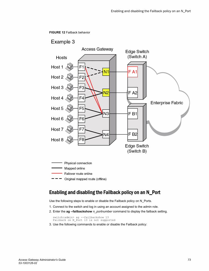
FIGURE 12 Failback behavior
Enabling and disabling the Failback policy on an N_PortUse the following steps to enable or disable the Failback policy on N_Ports.
1. Connect to the switch and log in using an account assigned to the admin role.2. Enter the ag --failbackshow n_portnumber command to display the failback setting.
switch:admin> ag --failbackshow 13Failback on N_Port 13 is not supported
3. Use the following commands to enable or disable the Failback policy:
Enabling and disabling the Failback policy on an N_Port
Access Gateway Administrator's Guide 7353-1003126-02

• Enter the ag --failbackenable n_portnumber command to enable failback.
switch:admin> ag --failbackenable 13Failback policy is enabled for port 13
• Enter the ag --failbackdisable n_portnumber command to disable failback.
switch:admin> ag --failbackdisable 13Failback policy is disabled for port 13
Enabling and disabling the Failback policy for a port groupUse the following steps to enable or disable the Failback policy on all the N_Ports belonging to thesame port group.
1. Connect to the switch and log in using an account assigned to the admin role.2. Use the following commands to enable or disable the Failback policy for a port group:
• Enter the ag --failbackenable pg pgid command to enable failback on a port group.
switch:admin> ag --failbackenable -pg 3Failback policy is enabled for port group 3
• Enter the ag --failbackdisable pg pgid command to disable failback on a port group.
switch:admin> ag --failbackdisable -pg 3Failback policy is disabled for port group 3
Upgrade and downgrade considerations for the Failback policy• Downgrading to Fabric OS v6.3.0 or earlier is supported.• Upgrading from Fabric OS v6.4.0 is supported.
Failback policy disabled on unreliable links (N_Port monitoring)Links from all N_Ports are monitored for the number of online and offline static change notifications(SCNs) that occur during a set time period (5 minutes). If the number of SCNs on a link exceeds a setthreshold, the link is considered unreliable , and failback is disabled for that N_Port. Failover continuesfor the port as needed. Once the number of SCNs drops below the set threshold, the port is deemedreliable again and failback is re-enabled. If the link from a preferred secondary N_Port for an F_Portbecomes unreliable, failover will not occur to that N_Port.
The default threshold is 25 SCNs per 5 minutes. You can modify the SCN threshold counter using thefollowing command.
ag --reliabilitycounterset "count"You can view counter settings using the following command.
ag --reliabilitycountershow
Considerations for Failback policy disabled on unreliable links
Consider the following when an N_Port link becomes reliable again after being unreliable:
• Preferred N_Port settings are enforced.• If failback is enabled, configured F_Ports will fail back to the N_Port.• If the configured F_Ports are offline, they will go back online.• If Device Load Balancing is enabled, rebalancing occurs.
Enabling and disabling the Failback policy for a port group
74 Access Gateway Administrator's Guide53-1003126-02
Trunking in Access Gateway modeThe hardware-based Port Trunking feature enhances management, performance, and reliability ofAccess Gateway N_Ports when they are connected to Brocade fabrics. Port trunking combines multiplelinks between the switch and AG module to form a single, logical port. This enables fewer individuallinks, thereby simplifying management. This also improves system reliability by maintaining in-orderdelivery of data and avoiding I/O retries if one link within the trunk fails. Equally important is that framed-based trunking provides maximum utilization of links between the AG module and the core fabric.
Trunking allows transparent failover and failback within the trunk group. Trunked links are more efficientbecause of the trunking algorithm implemented in the switching ASICs that distributes the I/O moreevenly across all the links in the trunk group.
Trunking in Access Gateway is mostly configured on the Edge switch. To enable this feature, you mustinstall the Brocade ISL license on both the Edge switch and the module running in AG mode and ensurethat both modules are running the same Fabric OS version. If a module already has an ISL trunkinglicense, no new license is required. After the trunking license is installed on a switch in AG mode andyou change the switch to standard mode, you can keep the same license.
NOTEN_Port trunking is not supported to HBAs connected to switches running in Access Gateway mode.N_Port trunking is only supported for HBAs connected to switches running in Native mode.
NOTEYou can also enable F_Ports on the Access Gateway switch for trunking using the portcfgtrunkportcommand.
How trunking worksTrunking in Access Gateway mode provides a trunk group between N_Ports on the AG module andF_Ports on the Edge switch module. With trunking, any link within a trunk group can go offline orbecome disabled, but the trunk remains fully functional and no reconfiguration is required. Trunkingprevents reassignments of the port ID when N_Ports go offline.
Configuring trunking on the Edge switchBecause AG trunking configuration is mostly on the Edge switch, information in this section is applicableto the Edge switch module and not the AG module. On the AG module, you only need to ensure that thetrunking license is applied and enabled. On the Edge switch, you must first configure an F_Port trunkgroup and statically assign an Area_ID to the trunk group. Assigning a Trunk Area (TA) to a port ortrunk group enables F_Port masterless trunking on that port or trunk group. On switches running inAccess Gateway mode, the masterless trunking feature trunks N_Ports because these are the onlyports that connect to the Enterprise fabric. When a TA is assigned to a port or trunk group, the ports willimmediately acquire the TA as the area of its port IDs (PIDs). When a TA is removed from a port ortrunk group, the port reverts to the default area as its PID.
NOTEBy default, trunking is enabled on all N_Ports of the AG; ensure that this feature is enabled on N_Portsthat are part of a port trunk group.
Trunking in Access Gateway mode
Access Gateway Administrator's Guide 7553-1003126-02

Trunk group creation
Port trunking is enabled between two separate Fabric OS switches that support trunking and where allthe ports on each switch reside in the same quad and are running the same speed. Trunk groups formwhen you connect two or more cables on one Fabric OS switch to another Fabric OS switch with portsin the same port group or quad. A port group or a quad is a set of sequential ports; for example, ports0-3. The Brocade 300 switch supports a trunk group with up to eight ports. The trunking groups arebased on the user port number, with eight contiguous ports as one group, such as 0-7, 8-15, 16-23and up to the number of ports on the switch.
Setting up trunking
Use the following steps to set up trunking.
1. Connect to the switch and log in using an account assigned to the admin role.2. Ensure that both modules (Edge switch and the switch running in AG mode) have the trunking
licenses enabled.3. Ensure that the ports have trunking enabled by issuing the portcfgshow command. If trunking is
not enabled, issue the portcfgtrunkport [slot/] port, 1 command.4. Ensure that the ports within a trunk have the same speed.5. Ensure that the ports within an ASIC trunk group are used to group the ports as part of a trunk on
the Edge switch or on an AG.6. Ensure that both modules are running the same Fabric OS versions.
Configuration management for trunk areasThe porttrunkarea command does not allow ports from different admin domains (ADs) and ports fromdifferent logical switches to join the same trunk area (TA) group.
When you assign a TA, the ports within the TA group will have the same Index. The Index that wasassigned to the ports is no longer part of the switch. Any Domain,Index (D,I) AD that was assumed tobe part of the domain may no longer exist for that domain because it was removed from the switch.
Trunk area assignment example
If you have AD1: 3,7; 3,8; 4,13; 4,14 and AD2: 3,9; 3,10, and then create a TA with Index 8 with portsthat have index 7, 8, 9, and 10. Then index 7, 9, and 10 are no longer with domain 3. This means thatAD2 does not have access to any ports because index 9 and 10 no longer exist on domain 3. Thisalso means that AD1 no longer has 3,7 in effect because Index 7 no longer exists for domain 3. AD1's3,8, which is the TA group, can still be seen by AD1 along with 4,13 and 4,14.
A port within a TA can be removed, but this adds the Index back to the switch. For example, the sameAD1 and AD2 with TA 8 holds true. If you remove port 7 from the TA, it adds Index 7 back to theswitch. That means AD1's 3,7 can be seen by AD1 along with 3,8; 4,13 and 4,14.
Assigning a trunk area
You must enable trunking on all ports to be included in a trunk area before you can create a trunkarea. Use the portCfgTrunkPort or switchCfgTrunk command to enable trunking on a port or on allports of a switch.
Issue the porttrunkarea command to assign a static TA on a port or port trunk group, to remove a TAfrom a port or group of ports in a trunk, and to display masterless trunking information.
Trunk group creation
76 Access Gateway Administrator's Guide53-1003126-02

You can remove specified ports from a TA using the porttrunkarea --disable command, however, thiscommand does not unassign a TA if its previously assigned Area_ID is the same address identifier(Area_ID) of the TA unless all the ports in the trunk group are specified to be unassigned. For moreinformation on the porttrunkarea command, enter help porttrunkarea or see the Fabric OS CommandReference Manual. F_Port trunking will not support shared area ports 16-47 on the Brocade FC8-48blades.
Address identifierTABLE 9
23 22 21 20 19 18 17 16 15 14 13 12 11 10 9 8 7 6 5 4 3 2 1 0
Domain ID Area_ID Port ID
1. Connect to the switch and log in using an account assigned to the admin role.2. Disable the ports to be included in the TA.3. Enable a TA for the appropriate ports. The following example enables a TA for ports 13 and 14 on
slot 10 with port index of 125.
switch:admin> porttrunkarea --enable 10/13-14 -index 1254. Display the TA port configuration (ports still disabled) using the porttrunkarea --show enabled
command.5. Enable the ports specified in step 3 using the portenable command.
switch:admin> portenable 10/13switch:admin> portenable 10/14
6. Show the TA port configuration after enabling the ports using the porttrunkarea --show enabledcommand. The ports that you enabled should appear in the output.
Enabling the DCC policy on a trunk
After you assign a Trunk Area, the porttrunkarea command checks whether there are any activeDevice Connection Control (DCC) policies on the port with the index TA, and then issues a warning toadd all the device WWNs to the existing DCC policy with index as TA. All DCC policies that refer to anIndex that no longer exist will not be in effect.
Use the following steps to enable the DCC policy on a trunk.
1. Add the WWN of all the devices to the DCC policy against the TA.2. Enter the secpolicyactivate command to activate the DCC policy.
You must enable the TA before issuing the secpolicyactivate command in order for security toenforce the DCC policy on the trunk ports.
3. Turn on the trunk ports.
Trunk ports should be turned on after issuing the secpolicyactivate command to prevent the portsfrom becoming disabled in the case where there is a DCC security policy violation.
Enabling trunking1. Connect to the switch and log in using an account assigned to the admin role.2. Disable the desired ports by entering the portdisable port command for each port to be included in
the TA.3. Enter the porttrunkarea--enable 3 command with the appropriate options to form a trunk group for
the desired ports. For example, if ports 36-39 were disabled in step 2, then the following example
Enabling the DCC policy on a trunk
Access Gateway Administrator's Guide 7753-1003126-02
command forms a trunk group for ports 36-39 with index 37. These will be connected to N_Ports onan AG module.
switch:admin> porttrunkarea --enable 36-39 -index 37Trunk area 37 enabled for ports 36, 37, 38 and 39.
4. Enter the portenable port command for each port in the TA to re-enable the desired ports, such asports 36-39.
5. Enter the switchshow command to display the switch or port information, including created trunks.
Disabling F_Port trunkingUse the following steps to disable F_Port trunking.
1. Connect to the switch and log in using an account assigned to the admin role.2. Enter the porttrunkarea --disable command.
switch:admin> porttrunkarea --disable 36-39ERROR: port 36 has to be disabledIf an error occurs as in the previous example, disable each port using the portdisable portcommand, and then reissue the command.
switch:admin> porttrunkarea --disable 36-39trunk area 37 disabled for ports 36, 37, 38 and 39.
Monitoring trunkingFor F_Port masterless trunking, you must install Filter, EE, or TT monitors on the F_Port trunk port.Whenever the master port changes, it is required to move the monitor to the new master port. Forexample, if a master port goes down, a new master is selected from the remaining slave ports. TheAdvanced Performance Monitor (APM) must delete the monitor from the old master and install themonitor on the new master port. If you attempt to add a monitor to a slave port, it is automaticallyadded to the master port.
AG trunking considerations for the Edge switch
Access Gateway trunking considerations for the Edge switch TABLE 10
Category Description
Area assignment You statically assign the area within the trunk group on the Edge switch. That group isthe F_Port masterless trunk. The static trunk area you assign must fall within theF_Port trunk group starting from port 0 on an Edge switch or blade.The static trunkarea you assign must be one of the port’s default areas of the trunk group.
Authentication Authentication occurs only on the F_Port trunk master port and only once per the entiretrunk. This behavior is the same as E_Port trunk master authentication. Because onlyone port in the trunk does FLOGI to the switch, and authentication follows FLOGI onthat port, only that port displays the authentication details when you issue theportshow command.
NOTEAuthentication is also supported on switches configured in AG mode.
Disabling F_Port trunking
78 Access Gateway Administrator's Guide53-1003126-02
Access Gateway trunking considerations for the Edge switch (Continued)TABLE 10
Category Description
Management Server Registered Node ID (RNID), Link Incident Record Registration (LIRR), and QuerySecurity Attributes (QSA) Extended Link Service Requests (ELSs) are not supportedon F_Port trunks.
Trunk area The port must be disabled before assigning a Trunk Area on the Edge switch to theport or removing a Trunk Area from a trunk group.You cannot assign a Trunk Area toports if the standby CP is running a firmware version earlier than Fabric OS v6.2.0.
PWWN The entire Trunk Area trunk group shares the same Port WWN within the trunk group.The PWWN is the same across the F_Port trunk that will have 0x2f or 0x25 as the firstbyte of the PWWN. The TA is part of the PWWN in the format listed in Table 11 .
Downgrade You can have trunking on, but you must disable the trunk ports before performing afirmware downgrade.
NOTERemoving a Trunk Area on ports running traffic is disruptive. Use caution beforeassigning a Trunk Area if you need to downgrade to a firmware earlier than Fabric OSv6.1.0.
Upgrade No limitations on upgrade to Fabric OS 7.1.0 if the F_Port is present on the switch.Upgrading is not disruptive.
HA Sync If you plug in a standby CP with a firmware version earlier than Fabric OS v6.1.0 and aTrunk Area is present on the switch, the CP blades will become out of sync.
Port Types Only F_Port trunk ports are allowed on a Trunk Area port. All other port types thatinclude F/FL/E/EX are persistently disabled.
Default Area Port X is a port that has its Default Area the same as its Trunk Area. The only time youcan remove port X from the trunk group is if the entire trunk group has the Trunk Areadisabled.
portCfgTrunkPort[slot/] port, 0
portCfgTrunkPort [slot/] port , 0 will fail if a Trunk Area is enabled on a port. The portmust be Trunk Area-disabled first.
switchCfgTrunk 0 switchCfgTrunk 0 will fail if a port has TA enabled. All ports on a switch must be TAdisabled first.
Port Swap When you assign a Trunk Area to a Trunk group, the Trunk Area cannot be portswapped; if a port is swapped, then you cannot assign a Trunk Area to that port.
Trunk Master No more than one trunk master in a trunk group. The second trunk master will bepersistently disabled with reason "Area has been acquired".
Fast Write When you assign a Trunk Area to a trunk group, the trunk group cannot have fast writeenabled on those ports; if a port is fast- write-enabled, the port cannot be assigned aTrunk Area.
FICON FICON is not supported on F_Port trunk ports. However, FICON can still run on portsthat are not F_Port trunked within the same switch.
Managing Policies and Features in Access Gateway Mode
Access Gateway Administrator's Guide 7953-1003126-02
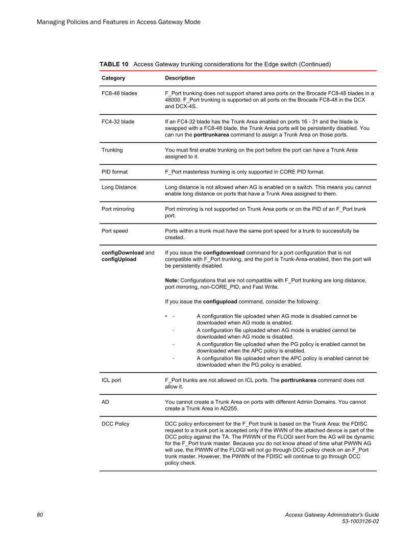
Access Gateway trunking considerations for the Edge switch (Continued)TABLE 10
Category Description
FC8-48 blades F_Port trunking does not support shared area ports on the Brocade FC8-48 blades in a48000. F_Port trunking is supported on all ports on the Brocade FC8-48 in the DCXand DCX-4S.
FC4-32 blade If an FC4-32 blade has the Trunk Area enabled on ports 16 - 31 and the blade isswapped with a FC8-48 blade, the Trunk Area ports will be persistently disabled. Youcan run the porttrunkarea command to assign a Trunk Area on those ports.
Trunking You must first enable trunking on the port before the port can have a Trunk Areaassigned to it.
PID format F_Port masterless trunking is only supported in CORE PID format.
Long Distance Long distance is not allowed when AG is enabled on a switch. This means you cannotenable long distance on ports that have a Trunk Area assigned to them.
Port mirroring Port mirroring is not supported on Trunk Area ports or on the PID of an F_Port trunkport.
Port speed Ports within a trunk must have the same port speed for a trunk to successfully becreated.
configDownload andconfigUpload
If you issue the configdownload command for a port configuration that is notcompatible with F_Port trunking, and the port is Trunk-Area-enabled, then the port willbe persistently disabled.
Note: Configurations that are not compatible with F_Port trunking are long distance,port mirroring, non-CORE_PID, and Fast Write.
If you issue the configupload command, consider the following:
• ‐ A configuration file uploaded when AG mode is disabled cannot bedownloaded when AG mode is enabled.
‐ A configuration file uploaded when AG mode is enabled cannot bedownloaded when AG mode is disabled.
‐ A configuration file uploaded when the PG policy is enabled cannot bedownloaded when the APC policy is enabled.
‐ A configuration file uploaded when the APC policy is enabled cannot bedownloaded when the PG policy is enabled.
ICL port F_Port trunks are not allowed on ICL ports. The porttrunkarea command does notallow it.
AD You cannot create a Trunk Area on ports with different Admin Domains. You cannotcreate a Trunk Area in AD255.
DCC Policy DCC policy enforcement for the F_Port trunk is based on the Trunk Area; the FDISCrequest to a trunk port is accepted only if the WWN of the attached device is part of theDCC policy against the TA. The PWWN of the FLOGI sent from the AG will be dynamicfor the F_Port trunk master. Because you do not know ahead of time what PWWN AGwill use, the PWWN of the FLOGI will not go through DCC policy check on an F_Porttrunk master. However, the PWWN of the FDISC will continue to go through DCCpolicy check.
Managing Policies and Features in Access Gateway Mode
80 Access Gateway Administrator's Guide53-1003126-02

Access Gateway trunking considerations for the Edge switch (Continued)TABLE 10
Category Description
D,I Zoning (D,I) AD
(D, I) DCC and (PWWN,I) DCC
Creating a Trunk Area may remove the Index ("I") from the switch to be grouped to theTrunk Area. All ports in a Trunk Area share the same "I". This means thatDomain,Index (D,I), which refers to an "I", that might have been removed, will no longerbe part of the switch.
Note : Ensure to include AD, zoning, and DCC when creating a Trunk Area.
You can remove the port from the Trunk Area to have the "I" back into effect. D,I willbehave as normal, but you may see the effects of grouping ports into a single "I".
Also, D,I continues to work for Trunk Area groups. The "I" can be used in D,I if the "I"was the "I" for the Trunk Area group.
Note : "I" refers to Index and D,I refers to Domain,Index.
Two masters Two masters is not supported in the same F_Port trunk group.
QoS Supported.
PWWN format for F_Port and N_Port trunk portsTABLE 11
NAA = 2 2f:xx:nn:nn:nn:nn:nn:nn
(1)
Port WWNs for:
switch FX_Ports.
The valid range of xx is [0 - FF], for maximumof 256.
NAA = 2 25:xx:nn:nn:nn:nn:nn:nn
(1)
Port WWNs for: switchFX_Ports
The valid range of xx is [0 - FF], for maximumof 256.
Trunking considerations for Access Gateway modeConsider the following for trunking in Access Gateway mode:
• Access Gateway trunking is not supported on M-EOS or third-party switches.• Trunk groups cannot span across multiple N_Port groups within an AG module in AG mode. Multiple
trunk groups are allowed within the same N_Port group. All ports within a trunk group must be part ofthe same port group; ports outside of a port group cannot form a trunk group.
• The ag -wwnmapshow command will not display trunking for device-mapped ports. If a device ismapped to a port with device mapping and that port is currently part of a trunk, then the device willuse that trunk. When trunking is used with the Device Load Balancing policy, then the load on eachtrunk will be proportional to the number of ports in that trunk. Use the ag -show command todetermine the devices using a particular trunk.
Upgrade and downgrade considerations for trunking in Access GatewaymodeUpgrading to Fabric OS v7.1.0 and downgrading to Fabric OS v6.4.0 and earlier is supported.
Trunking considerations for Access Gateway mode
Access Gateway Administrator's Guide 8153-1003126-02

Adaptive Networking on Access GatewayAdaptive Networking (AN) services ensure bandwidth for critical servers, virtual servers, orapplications in addition to reducing latency and minimizing congestion. Adaptive Networking in AccessGateway works in conjunction with the Quality of Service (QoS) feature on Brocade fabrics. Fabric OSprovides a mechanism to assign traffic priority, (high, medium, or low) for a given source anddestination traffic flow. By default, all flows are marked as medium.
You can configure the ingress rate limiting and SID/DID traffic prioritization levels of QoS for thefollowing configurations:
• Supported HBA to AG to switch• Unsupported HBA to AG to switch• HBA (all) to Edge AG to Core AG to switch
For additional information on the QoS feature for Brocade adapters, refer to the BrocadeAdaptersAdministrator's Guide .
QoS: Ingress rate limitingIngress rate limiting restricts the speed of traffic from a particular device to the switch port. Onswitches in AG mode, you must configure ingress rate limiting on F_Ports.
For more information and procedures for configuring this feature, refer to "Ingress Limiting" in theFabric OS Administrator’s Guide .
QoS: SID/DID traffic prioritizationSID/DID traffic prioritization allows you to categorize the traffic flow between a given host and target ashaving a high or low priority; the default is medium. For example, you can assign online transactionprocessing (OLTP) to a high priority and the backup traffic to a low priority.
For detailed information on this feature, refer to "QoS: SID/DID traffic prioritization" in the Fabric OSAdministrator’s Guide.
The figure below shows the starting point for QoS in various Brocade and non-Brocade configurations.
Adaptive Networking on Access Gateway
82 Access Gateway Administrator's Guide53-1003126-02

FIGURE 13 Starting point for QoS
Upgrade and downgrade considerations for Adaptive Networking in AGmodeUpgrading to Fabric OS v7.1.0 from Fabric OS v6.4.0 is supported. Note the following considerationswhen upgrading to Fabric OS v7.1.0 from Fabric OS v6.2.X and earlier and downgrading from FabricOS v7.1.0 to Fabric OS v6.2.X and earlier:
• If any of the AG QoS-enabled ports are active and you attempt a firmware downgrade, thedowngrade is prevented. You must disable the QoS-enabled ports before performing a firmwaredowngrade.
• Upgrades from earlier versions to Fabric OS v7.1.0 are allowed, but AG QoS-enabled ports do notbecome effective until the ports are disabled or enabled so that QoS mode can be negotiated on theISLs.
Adaptive Networking on Access Gateway considerations• QoS is configured in the fabric, as normal, and not on the AG module.• QoS on Access Gateway is only supported on Fabric OS v6.3 and later.• You should disable HBA QoS if connected to a Fabric OS v6.2 AG switch.• Disable QoS on an AG port if it connects with a switch running Fabric OS v6.2. Otherwise, the port
will automatically disable with an error. To recover, disable QoS on the port, and then enable theport.
• Disabling QoS on online N_Ports in the same trunk can cause the slave N_Port ID Virtualization(NPIV) F_Port on the Edge switch to become persistently disabled with "Area has been acquired."This is expected behavior because after QoS is disabled, the slave NPIV F_Port on the Edge switchalso tries to come up as a master. To avoid this issue, simply persistently enable the slave F_Port onthe switch.
Upgrade and downgrade considerations for Adaptive Networking in AG mode
Access Gateway Administrator's Guide 8353-1003126-02

• QoS takes precedence over ingress rate limiting• Ingress rate limiting is not enforced on trunked ports.
Per-Port NPIV login limitThe Per-Port NPIV login limit feature allows you to set a specific maximum NPIV login limit onindividual ports. This feature works in both Native and Access Gateway modes. Using this feature, youcan use additional tools to design and implement a virtual infrastructure. In Access Gateway mode,this feature allows smaller login limits for F_Ports and larger limits for N_Ports. Note that N_Ports arerestricted by the NPIV login limit of the connecting port on the Edge switch.
Note the following aspects of this feature:
• Upgrading between Fabric OS v6.4.0 and v7.1.0 will retain the NPIV settings.• The value that you set is persistent across reboots and firmware upgrades.• This feature supports virtual switches, so each port can have a specific NPIV login limit value in
each logical switch.• The login limit default is 126. This value will be set for a port when the portCfgDefault command is
used to reset port default values.• Before changing the login limits, you must disable the port.• This feature only applies to ports enabled for NPIV operation. To enable NPIV functionality for a
port, you can use the portCfgNPIVPort --enable command when the switch is in Fabric OS Nativemode. For details, refer to the Fabric OS Command Reference Manual .
Setting the login limitUse the following procedure to set the NPIV login limit for a port.
1. Connect to the switch and log in using an account assigned to the admin role.2. Disable the port by entering the portdisable port command.3. Enter the portcfgnpiv --setloginlimit [Slot/]Port loginlimit command to set the login limit. For
example, the following example sets the login limit on port 12 to 200.
portcfgnpivport --setloginlimit 12 200
Duplicate PWWN handling during device loginHandling of logins from two devices using the same PWWN follows standards for all Fabric OSswitches. Having two devices with the same PWWN logged into the fabric at the same time may notbe desirable as there have been cases when ports coming online get stuck in G_Port state in the AGswitch. You can configure three policies:
• Default - The Access Gateway switch will not accept a second login request from a PWWN when adevice with the same PWWN has already logged into the fabric. The second request with similarPWWN will be rejected and the port will be persistently disabled with reason as "Duplicate PortWWN detected."
• Enforced login - The second login request will have precedence over the existing login and AccessGateway will accepts the login.
• Mixed - This option takes port type into consideration. The second login request will haveprecedence over the existing login in case of a duplicate entry exit on the F_Port with an NPIV
Per-Port NPIV login limit
84 Access Gateway Administrator's Guide53-1003126-02

device logged in. The first login takes precedence over the second login request in case of aduplicate entry exit on the F_Port without any NPIV device logged in.
You can configure different handling of duplicate PWWNs other than the default operation using theconfigure command through the F_Port login parameters. For more information on configuration andhandling of duplicate PWWNs during device login, refer to the "Duplicate PWWN handling during devicelogin" section in the Fabric OS Administrator’s Guide .
This feature is supported in the following configurations:
• AG switch connected to AG switch in cascaded configuration.• AG switch connected to Brocade fabric switch.• AG switch connected to a Brocade Host Bus Adapter (HBA).
Performance MonitoringPerformance monitoring is available through the Flow Vision "Flow Monitor" for platforms using FabricOS 7.2 and later. Legacy Advanced Performance Monitoring features are also an option.
Flow MonitorFlow Vision is a licensed feature supported on platforms using Fabric OS 7.2 and later. It provides aunified platform to manage traffic-related applications on Fabric OS devices. Storage administrators canuse this platform to simulate, monitor, and capture the network’s traffic patterns and to make capacity-planning decisions based on the collected statistical data.
To access Flow Vision, the Fabric Vision (FV) license or both the Fabric Watch (FW) and the AdvancedPerformance Monitor (APM) licenses must be installed on the hardware platform.
The Flow Monitor component of Flow Vision is supported by Access Gateway. Flow Monitor allows youto monitor the network’s traffic pattern and provides statistics to make capacity planning decisionsbased on the collected data. Flow Monitor provides a single interface to manage flows and unifiesdifferent performance monitoring features such as end-to-end monitors and frame monitors.
Flow Monitor expands on basic performance monitoring by allowing you to monitor any hardware-supported flow parameters and define your own flows using combinations of source and destinationdevices, source and destination IDs, LUN IDs, CSCTL values, and frame types as parameters.
Following are examples of monitors that you can replicate using Flow Monitor:
• End to End Monitor - This measures the traffic in terms of word count between a pair of ports (hostand target). Use this to view end-to end traffic values on an Access Gateway.
• Frame monitoring - Set up an SCSI monitor so that you can view the -frametype frame and bytecount for a flow.
• LUN monitoring - This allows you to view the -frametype frame and byte count for a specific LUN.• Flow learning monitor - This learns flows going through a specific F_Port in the Access Gateway.• DST monitor - This provides the legacy support equivalent to a fmmonitor.
Access Gateway switches support flow monitors on F_Ports only, and only the ingress port parameter issupported. For more information on using Flow Monitor features for Access Gateway in Flow Vision,refer to the Flow Vision Administrator's Guide .
Performance Monitoring
Access Gateway Administrator's Guide 8553-1003126-02

Legacy performance monitoring featuresInstead of Flow Monitor, you can use the legacy end-to-end and frame monitoring features availablethrough Advanced Performance Monitoring (APM). These legacy features are available on platformsusing Fabric OS 7.2 and earlier. The following licenses must be appropriately installed on the AGswitch to use the end-to-end and frame monitors:
• APM• Fabric Watch
Use the following Fabric OS commands used to manage APM in switch mode to manage end to endand frame monitoring in AG mode. Refer to the Fabric OS Command Reference Manual and FabricOS Administrator’s Guide for details.
• perfAddEEMonitor• perfMonitorClear• perfMonitorShow --class EE <port#>• perfResourceShow• perfCfgSave• perfCfgClear• perfCfgRestore• fmmonitor
You can also use Fabric Watch to configure thresholds corresponding to specific frame monitors Referto the Fabric Watch Administrator's Guide for details.
End-to-end monitors
End-to-end monitors measure the traffic between a host and target pair by counting the number ofwords in Fibre Channel frames for a specified Source ID (SID) and Destination ID (DID) pair. An end-to-end performance monitor includes these counts:
• RX_COUNT - Words in frames received at the port• TX_COUNT - Words in frames transmitted from the port
To enable end-to-end performance monitoring, you must install an end-to-end monitor on an F_Portusing the perfAddEEMonitor command, specifying the SID-DID pair (in hexadecimal). End-to-endmonitoring on N-ports is not supported in AG mode. Complete details of the perfAddEEMonitorcommand parameters are provided in the Fabric OS Command Reference Manual .
NOTEEnd-to-end monitors are not supported on logical EX, VE, VEX, Mirror, or FCoE ports.
For more information on end-to-end monitoring, including the following topics, refer to the "End-to-endperformance monitoring" section in the Fabric OS Administrator’s Guide :
• General feature information• Fabric OS commands for end-to-end monitors• The maximum number of end-to-end monitors per switch model• Setting a mask for a monitor• Deleting a monitor
Frame monitors
Frame monitors count the number of times a frame with a particular pattern is transmitted by a portand generate alerts when thresholds are crossed. Frame monitoring is achieved by defining a filter, or
Legacy performance monitoring features
86 Access Gateway Administrator's Guide53-1003126-02
frame type, for a particular purpose. The frame type can be a standard type (for example, an SCSI readcommand filter that counts the number of SCSI read commands that have been transmitted by the port)or a frame type that you can customize for a particular use. For a complete list of the standard, pre-defined frame types, see the fmMonitor command description in the Fabric OS Command ReferenceManual.
To enable frame monitoring, you must install a frame monitor on an F_Port or N_Port in the AG switchusing the fmMonitor command. Using options in this command, you can also perform the followingtasks:
• Create a new frame type.• Delete a specified frame type.• Delete the set of ports on which the specified frame type can be monitored.• Add a set of ports for which a specific frame type can be monitored.• Save a set of ports on which the specified frame type can be monitored.• Show different frame types configured on the switch, as well as frame counters.• Change properties for a particular frame type, such as thresholds and bit pattern.• Clear a set of ports on which the specified frame type is monitored to the persistent configuration.
Complete details of the fmMonitor command parameters are provided in the Fabric OS CommandReference Manual.
The thConfig command can be used for advanced configuration of filter thresholds corresponding toframe monitors. See the Fabric Watch Administrator’s Guide for more information about using thiscommand.
For more information on frame monitoring, including the following topics, refer to the "Frame monitoring"section in the Fabric OS Administrator’s Guide :
• General feature information• Maximum number of frame monitors and offsets per port for different switch models• Virtual fabric considerations• Adding frame monitors to a port• Removing frame monitors from a port• Creating custom frame types to be monitored• Deleting frame types• Saving frame monitor configurations• Displaying frame monitors• Clearing frame monitor counters
Limitations for using legacy APM features
The following limitations apply to using legacy APM features on an AG switch:
• The Top Talker and ISL monitoring features used for APM in switch mode are not supported on anAG switch.
• APM on an AG switch is not supported in Web Tools.• Configuration file upload and download of end-to-end and filter monitor configurations is not
supported in the Fabric OS v7.0.0 release.• When downgrading to a pre-Fabric OS v7.0.0 release, the user is notified to remove all the end-to-
end and frame monitors installed.• When switching between AG mode and non-AG mode, the user is notified to remove all the end-to-
end and frame monitors installed.
Limitations for using legacy APM features
Access Gateway Administrator's Guide 8753-1003126-02

Considerations for the Brocade 6505 and 6510The Brocade 6505 and 6510 can function in either Fabric OS Native mode or Brocade AccessGateway mode. These switches are shipped in Fabric OS Native mode. They are also supported inAccess Gateway cascaded configurations. All POD licenses must be present to support AccessGateway for all releases prior to Fabric OS 7.3.0. However, starting with Fabric OS 7.3.0, all PODlicenses are not required.
Considerations for the Brocade 6505 and 6510
88 Access Gateway Administrator's Guide53-1003126-02

SAN Configuration with Access Gateway
● Connectivity of multiple devices overview.......................................................................89● Direct target attachment..................................................................................................89● Target aggregation..........................................................................................................91● Access Gateway cascading............................................................................................ 92● Fabric and Edge switch configuration............................................................................. 93● Connectivity to Cisco fabrics........................................................................................... 94● Rejoining Fabric OS switches to a fabric........................................................................ 95
Connectivity of multiple devices overviewThis chapter describes how to connect multiple devices to a switch in Access Gateway (AG) mode, anddiscusses Edge switch compatibility, target aggregation, direct target attachment, port requirements,NPIV HBA, and interoperability. Switches in AG mode can connect to third-party fabrics with thefollowing firmware versions:
• Fabrics operating with M-EOSc v9.6.2 or later and M-EOSn v9.6 or later.• Cisco fabrics that support standards-based NPIV.
Considerations for connecting multiple devicesConsider the following points when connecting multiple devices to a switch in AG mode:
• AG does not support daisy chaining when two AG devices are connected to each other in a loopconfiguration.
• Loop devices and FICON channels/control unit connectivity are not supported.• When a switch is in AG mode, it can be connected to NPIV-enabled HBAs, or F_Ports that are NPIV-
aware. Access Gateway supports NPIV industry standards per FC-LS-2 v1.4.
Direct target attachmentFCP targets can directly connect to an AG module instead of through a fabric connection, as illustratedin the figure below.
Access Gateway Administrator's Guide 8953-1003126-02

FIGURE 14 Direct target attachment to switch operating in AG mode
Although target devices can be connected directly to AG ports, it is recommended that the switchoperating in AG mode be connected to the core fabric.
Considerations for direct target attachmentConsider the following points for direct target attachment:
• Direct target attachment to AG is only supported if the AG module is also connected to a corefabric. A switch module running in AG mode does not provide Name Services on its own, androuting to the target devices must be established by the core fabric.
• Hosts and targets cannot be mapped to the same N_Port.• Redundant configurations should be maintained so that when hosts and targets fail over or fail
back, they do not get mapped to a single N_Port.• Hosts and targets should be in separate port groups.• Direct target attachment configurations are not enforced.
Considerations for direct target attachment
90 Access Gateway Administrator's Guide53-1003126-02

Target aggregationAccess Gateway mode is normally used as host aggregation. In other words, a switch in AG modeaggregates traffic from a number of host systems onto a single uplink N_Port. Similarly, many targetscan be aggregated onto to a single uplink N_Port, as shown in the figure below. Target aggregation hasmany applications. As one example, you can consolidate targets with various lower Fibre Channelspeeds (such as 1, 2, or 4 Gbps) onto a single high-speed uplink port to the core fabric. This reducesthe number of core fabric ports used by target devices and allows higher scalability.
FIGURE 15 Target aggregation
Target aggregation
Access Gateway Administrator's Guide 9153-1003126-02

Access Gateway cascadingAccess Gateway cascading is an advanced configuration supported in Access Gateway mode. AccessGateway cascading allows you to further increase the ratio of hosts to fabric ports to beyond what asingle switch in AG mode can support.
Access Gateway cascading allows you to link two Access Gateway (AG) switches back to back. TheAG switch that is directly connected to the fabric is referred to as the Core AG. In this document, theAG switch connected to the device is referred to as the Edge AG.
FIGURE 16 Access Gateway cascading
AG cascading provides higher over-subscription because it allows you to consolidate the number ofports going to the main fabric. There is no license requirement to use this feature.
Access Gateway cascading considerationsNote the following configuration considerations when cascading Access Gateways:
• Only one level of cascading is supported. Note that several Edge AGs can connect into a singleCore AG to support an even higher consolidation ratio.
• AG trunking between the Edge and Core AG switches is not supported. Trunking between the CoreAG switch and the fabric is supported.
• It is recommended that you enable Advanced Device Security (ADS) policy on all AG F_Ports thatare directly connected to devices.
• APC policy is not supported when cascading.• Loopbacks (Core AG N_Port to Edge AG F_Port) are not allowed.• The agshow command issued on the fabric will discover only the Core AG switches. If issued as
agshow --nameAG name, then the F_Ports of both the Core and Edge AG switches will be shownfor the Core AG switch.
Access Gateway cascading
92 Access Gateway Administrator's Guide53-1003126-02
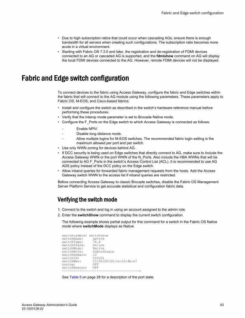
• Due to high subscription ratios that could occur when cascading AGs, ensure there is enoughbandwidth for all servers when creating such configurations. The subscription ratio becomes moreacute in a virtual environment.
• Starting with Fabric OS 7.3.0 and later, the registration and de-registration of FDMI devicesconnected to an AG or cascaded AG is supported, and the fdmishow command on AG will displaythe local FDMI devices connected to the AG. However, remote FDMI devices will not be displayed.
Fabric and Edge switch configurationTo connect devices to the fabric using Access Gateway, configure the fabric and Edge switches withinthe fabric that will connect to the AG module using the following parameters. These parameters apply toFabric OS, M-EOS, and Cisco-based fabrics:
• Install and configure the switch as described in the switch’s hardware reference manual beforeperforming these procedures.
• Verify that the interop mode parameter is set to Brocade Native mode.• Configure the F_Ports on the Edge switch to which Access Gateway is connected as follows:
‐ Enable NPIV.‐ Disable long distance mode.‐ Allow multiple logins for M-EOS switches. The recommended fabric login setting is the
maximum allowed per port and per switch.• Use only WWN zoning for devices behind AG.• If DCC security is being used on Edge switches that directly connect to AG, make sure to include the
Access Gateway WWN or the port WWN of the N_Ports. Also include the HBA WWNs that will beconnected to AG F_Ports in the switch’s Access Control List (ACL). It is recommended to use AGADS policy instead of the DCC policy on the Edge switch.
• Allow inband queries for forwarded fabric management requests from the hosts. Add the AccessGateway switch WWN to the access list if inband queries are restricted.
Before connecting Access Gateway to classic Brocade switches, disable the Fabric OS ManagementServer Platform Service to get accurate statistical and configuration fabric data.
Verifying the switch mode1. Connect to the switch and log in using an account assigned to the admin role.2. Enter the switchShow command to display the current switch configuration.
The following example shows partial output for this command for a switch in the Fabric OS Nativemode where switchMode displays as Native.
switch:admin> switchshowswitchName: switchswitchType: 76.6switchState: OnlineswitchMode: NativeswitchRole: SubordinateswitchDomain: 13switchId: fffc01switchWwn: 10:00:00:05:1e:03:4b:e7zoning: OFFswitchBeacon: OFF----------------------------------------=See Table 5 on page 28 for a description of the port state.
Fabric and Edge switch configuration
Access Gateway Administrator's Guide 9353-1003126-02

If the switch is in Native mode, you can enable AG mode; otherwise, set the switch to Native mode,and then reboot the switch.
Enabling NPIV on M-EOS switches1. Connect to the switch and log in as admin on the M-EOS switch.2. Enable Open Systems Management Server (OSMS) services by entering the following commands.
For the Mi10K switch, enter the following command.
fc osmsState vfid state In the command, vfid is the virtual fabric identification number. The state variable can be enable forthe enabled state or disable for the disabled state.
The osmsState variable can be enable or 1 for the enabled state or disable or 0 for the disabledstate.
3. Enable NPIV functionality on the Edge fabric ports so that multiple logins are allowed for each port.Enter the following command on the M-EOS switch to enable NPIV on the specified ports.
config NPIVYour M-EOS switch is now ready to connect.
NOTEYou can run the agshow command to display Access Gateway information registered with thefabric. When an Access Gateway is exclusively connected to non-Fabric-OS-based switches, it willnot show up in the agshow output on other Brocade switches in the fabric.
Connectivity to Cisco fabricsWhen connecting a switch in Access Gateway mode to a Cisco fabric, you need to make sure thatNPIV is enabled on the connecting switch and that Fabric OS v3.1 or later is used.
Enabling NPIV on a Cisco switch1. Log in as admin on the Cisco MDS switch.2. Enter the show version command to determine if you are using the correct SAN operating system
version and if NPIV is enabled on the switch.3. Enter the following commands to enable NPIV:
configure terminalnpiv enable
4. Press Ctrl-Z to exit.5. Enter the following commands to save the MDS switch connection:
copy run start Your Cisco switch is now ready to connect to a switch in Access Gateway mode.
Enabling NPIV on M-EOS switches
94 Access Gateway Administrator's Guide53-1003126-02

Rejoining Fabric OS switches to a fabric
When a switch reboots after AG mode is disabled, the Default zone is set to no access. Therefore, theswitch does not immediately join the fabric to which it is connected. Use one of the following methods torejoin a switch to the fabric:
• If you saved a Fabric OS configuration before enabling AG mode, download the configuration usingthe configDownload command.
• If you want to rejoin the switch to the fabric using the fabric configuration, use the followingprocedure.
To rejoin the Fabric OS switch to a fabric, perform the following steps:
1. Connect to the switch and log in using an account assigned to the admin role.2. Enter the switchDisable command to disable the switch.3. Enter the defZone --allAccess command to allow the switch to merge with the fabric.4. Enter the cfgSave command to commit the Default zone changes.5. Enter the switchEnable command to enable the switch and allow it to merge with the fabric.
The switch automatically rejoins the fabric.
Reverting to a previous configuration1. Connect to the switch and log in using an account assigned to the admin role.2. Enter the switchDisable command to disable the switch.3. Enter the configDownload command to revert to the previous configuration.4. Enter the switchEnable command to bring the switch back online.
The switch automatically joins the fabric.
Rejoining Fabric OS switches to a fabric
Access Gateway Administrator's Guide 9553-1003126-02

Reverting to a previous configuration
96 Access Gateway Administrator's Guide53-1003126-02

Troubleshooting
The following table provides troubleshooting information for Fabric OS switches in AG mode.
Troubleshooting TABLE 12
Problem Cause Solution
Switch is not inAccess Gatewaymode
Switch is in Nativeswitch mode
Disable switch using the switchDisable command.
Enable Access Gateway mode using the ag --modeenablecommand.
Answer yes when prompted; the switch reboots.
Log in to the switch.
Display the switch settings using the switchShow command.Verify that the field switchMode displays Access Gateway mode.
NPIV disabled onEdge switch ports
Inadvertently turned off On the Edge switch, enter the portCfgShow command.
Verify that NPIV status for the port to which Access Gateway isconnected is ON.
If the status displays as "--" NPIV is disabled. Enter theportCfgNpivPort port_number command with the enable option toenable NPIV.
Repeat this step for each port as required.
Need to reconfigureN_Port and F_Ports
Default port setting notadequate for customerenvironment
Enter the portCfgShow command.
For each port that is to be activated as an N_Port, enter theportCfgNport port_number command with the 1 option.
All other ports remain as F_Ports.
To reset the port to an F_Port, enter the portCfgNpivPortport_number command with the disable option.
LUNs are not visible Zoning on fabric switchis incorrect.
Port mapping onAccess Gateway modeswitch is incorrect.
Cabling not properlyconnected.
Verify zoning on the Edge switch.
Verify that F_Ports are mapped to an online N_Port. See Table 7on page 31.
Perform a visual inspection of the cabling; check for issues such aswrong ports, twisted cable, or bent cable. Replace the cable andtry again. Ensure the F_Port on AG module is enabled and active.
Access Gateway Administrator's Guide 9753-1003126-02

Troubleshooting (Continued)TABLE 12
Problem Cause Solution
Failover is notworking
Failover disabled onN_Port.
Verify that the failover and failback policies are enabled, as follows:
Enter the ag --failoverShow command with the port_numberoption.
Enter the ag --failbackShow command with the port_numberoption.
Command returns "Failback (or Failover) on N_Port port_numberis supported."
If it returns, "Failback (or Failover) on N_Port port_number is notsupported." Refer to Adding a preferred secondary N_Port(optional) on page 69.
Access Gateway ismode not wanted
Access Gateway mustbe disabled.
Disable switch using the switchDisable command.
Disable Access Gateway mode using the ag --modeDisablecommand.
Answer yes when prompted; the switch reboots.
Log in to the switch.
Display the switch settings using the switchShow command.Verify that the field switchMode displays Fabric OS Native mode.
"Login Rejected byFC stack" messageson console may beseen during F_Portand N_Portdisruptions onBrocade 8470 in AGmode.
The CNA host isretrying a login beforethe switch has finishedprecessing a previousfabric logout (LOGO)attempt.
Messages display as designed. After the switch has completedLOGO processing, it will accept another login.
Troubleshooting
98 Access Gateway Administrator's Guide53-1003126-02
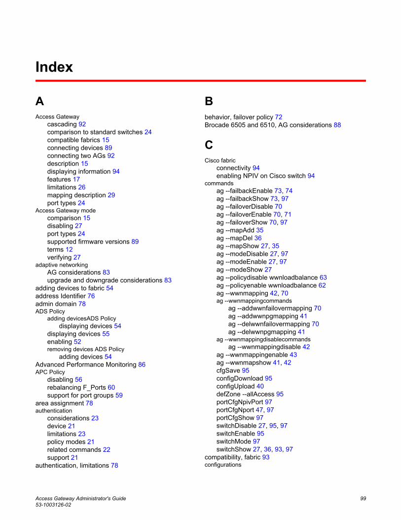
Index
AAccess Gateway
cascading 92comparison to standard switches 24compatible fabrics 15connecting devices 89connecting two AGs 92description 15displaying information 94features 17limitations 26mapping description 29port types 24
Access Gateway modecomparison 15disabling 27port types 24supported firmware versions 89terms 12verifying 27
adaptive networkingAG considerations 83upgrade and downgrade considerations 83
adding devices to fabric 54address Identifier 76admin domain 78ADS Policy
adding devicesADS Policydisplaying devices 54
displaying devices 55enabling 52removing devices ADS Policy
adding devices 54Advanced Performance Monitoring 86APC Policy
disabling 56rebalancing F_Ports 60support for port groups 59
area assignment 78authentication
considerations 23device 21limitations 23policy modes 21related commands 22support 21
authentication, limitations 78
Bbehavior, failover policy 72Brocade 6505 and 6510, AG considerations 88
CCisco fabric
connectivity 94enabling NPIV on Cisco switch 94
commandsag --failbackEnable 73, 74ag --failbackShow 73, 97ag --failoverDisable 70ag --failoverEnable 70, 71ag --failoverShow 70, 97ag --mapAdd 35ag --mapDel 36ag --mapShow 27, 35ag --modeDisable 27, 97ag --modeEnable 27, 97ag --modeShow 27ag --policydisable wwnloadbalance 63ag --policyenable wwnloadbalance 62ag --wwnmapping 42, 70ag --wwnmappingcommands
ag --addwwnfailovermapping 70ag --addwwnpgmapping 41ag --delwwnfailovermapping 70ag --delwwnpgmapping 41
ag --wwnmappingdisablecommandsag --wwnmappingdisable 42
ag --wwnmappingenable 43ag --wwnmapshow 41, 42cfgSave 95configDownload 95configUpload 40defZone --allAccess 95portCfgNpivPort 97portCfgNport 47, 97portCfgShow 97switchDisable 27, 95, 97switchEnable 95switchMode 97switchShow 27, 36, 93, 97
compatibility, fabric 93configurations
Access Gateway Administrator's Guide 9953-1003126-02

enabling switch 95limitations with configdownload command 78merging switch with fabric 95re-joining switch to fabric 95saving 95using configdownload command 95
DD_Port
description 24descriptionD_Port
configurations supported 48saving port mappings 49tests 48
daisy chaining 89DCC policy
adding WWN 77enabling 77limitation creating TA 78
default area, removing ports 78device load balancing 59device load balancing policy
APC policy 63considerations 63disabling 63enabling 62trunking 63, 81
device mappingadding a secondary N_Port 70considerations 45disabling 42enabling 43failover 69feature overview 37pre-provisioning 43removing secondary N_Port 70static vs. dynamic mapping 40to port group 41to ports 42VMware configuration 44VMware considerations 44
devicesattaching multiple devices 89
disabling switchswitchDisable 95
domain,Index 76downgrading 78downgrading considerations 55, 56duplicate PWWWN handling during login 84dynamic vs. static mapping 40
EEdge switch
FLOGI 93long distance mode setting 93NPIV 93settings 93
end to end monitors 86ensure port online state 47
FF_Port
adding external port on embedded switch 46description 24mapping, example 29maximum number mapped to N_Port 46settings, Edge switch 93shared area ports 76trunking setup 76
fabriccompatibility 93inband queries 93join 95logins 93management server platform 93zoning scheme 93
Fabric OS features supported 17Fabric OS management server platform servicesettings 93failback policy
upgrade and downgrade considerations 74failback policy example 66, 72failover
device mapping 69failover example 66failover policy
behavior 66configurations for port mapping 66enabling 71example 66, 72port mapping 66
fast write limitation 78FICON, F_Port trunk ports 78Flow Monitor 85Flow Vision 85frame monitors 86
HHA sync, TA present 78
100 Access Gateway Administrator's Guide53-1003126-02

IICL ports, limitations 78inband queries 93initiator and target port considerations 35
Jjoin fabric 95
Llimitations
device load balancing 63direct connections to target devices 26loop devices not supported 26
login balancing considerations 60long distance mode, Edge switch 93
Mmanaged fabric name monitoring
disabling 61displaying current timeout value 61enabling 61setting timeout values 61
management server 78mapping
considerations 44device 29devices to ports device mapping
adding devices to N_Ports 42device to port groups 41example 29port 29ports 29
mapping priority 29masterless trunking 78M-EOS switch, enabling NPIV 94monitors
end to end 86frame 86
NN_Port
configurations 46description 24displaying configurations 47failover in a PG 61mapping example 29masterless trunking 75maximum number supported 46multiple trunk groups 81trunk groups 81unlock 47unlocking 47
N_Port configurationsdisplaying 47
N_Portsunlocking 47
native switchMode 93non disruptive 78NPIV
Edge switch 93enabling on Cisco switch 94enabling on M-EOS switch 94login limit 84support 89
Pperformance monitoring
Flow Monitor 85legacy monitoring features 86
per port NPIV login limit 84persistent ALPA
clearing ALPA values 65considerations 65deleting hash table data 64disabling 64enabling 64flexible ALPA value 64reboot 65stringent ALPA value 64tables 64value types 64
Persistent ALPAsupport 63
persisting port online state 47policies
advance device security 52enabling DCC policy 77enforcement matrix 51port grouping 56showing current policies 51using policyshow command 51
port
Access Gateway Administrator's Guide 10153-1003126-02

comparison 24mapping 29requirements 89types 24
portcfgpersistentenable command 47port group
add N_Port 58createport group
add N_Port 60delete N_Port 58disabling 59enabling logging balancing mode 60login balancing mode 59managed fabric name monitoring mode 59remove port group 58rename 59
port grouping policyconsiderations 61downgrading considerations 62
Port Grouping policyusing portcfgnport command 47
port mappingadding F_Ports to N_Ports 35adding ports 35adding secondary N_Port 69considerations for initiator and target ports 35deleting secondary N_Port 69maximum number of F_Ports 46removing F_Ports from N_Ports 36
Port mirroring, not supported 78port state, description 28port swap, not swapping TA 78port types, limitations 78preferred secondary N_Port
login balancing mode 69online 66
PWWNduplicate handling during login 84format 78sharing TA trunk group 78
QQoS
firmware downgrade 83ingress rate limiting 82SID/DID traffic prioritization 82
Rremoving devices from switch 54removing trunk ports 78requirements, ports 89
Ssettings
FLOGI 93inband queries 93management server platform 93zone, no access 95
static vs. dynamic mapping 40supported hardware and software 11switch mode, verify 93
Tterms 12trunk area
assign 76configuration management 76disabling 78remove ports 76standby CP 78using the porttrunkarea command 78
trunk groups, create 76trunking
configuring on edge switch 75considerations in AG module 81considerations on edge switch 78disabling 78enabling 77, 78license 75
trunk master, limitation 78
Uunlock N_Port 47upgrading 78
VVMware configuration for device mapping 44
Zzoning
102 Access Gateway Administrator's Guide53-1003126-02

schemes 93setting 95
Access Gateway Administrator's Guide 10353-1003126-02

104 Access Gateway Administrator's Guide53-1003126-02