![Schottky Barrier Heights Extraction of an Atomically Flat Ni ...Schottky-Barrier MOSFET Technology”, IEEE Transactions on Electron Devices, 53, p.1048-p.1058 (2006) [1.4] W. Mizubayashi,](https://static.fdocuments.net/doc/165x107/60e94ab2f3e0e511165d0cec/schottky-barrier-heights-extraction-of-an-atomically-flat-ni-schottky-barrier.jpg)
Accepted Road Safety Barrier Systems and Devices
161
Accepted Road Safety Barrier Systems and Devices September 2021
Transcript of Accepted Road Safety Barrier Systems and Devices

Accepted Road Safety Barrier Systems and Devices September 2021

Accepted Road Safety Barrier Systems and Devices, Transport and Main Roads, September 2021
Copyright © The State of Queensland (Department of Transport and Main Roads) 2021. Licence
This work is licensed by the State of Queensland (Department of Transport and Main Roads) under a Creative Commons Attribution (CC BY) 4.0 International licence. CC BY licence summary statement In essence, you are free to copy, communicate and adapt this work, as long as you attribute the work to the State of Queensland (Department of Transport and Main Roads). To view a copy of this licence, visit: https://creativecommons.org/licenses/by/4.0/ Translating and interpreting assistance
The Queensland Government is committed to providing accessible services to Queenslanders from all cultural and linguistic backgrounds. If you have difficulty understanding this publication and need a translator, please call the Translating and Interpreting Service (TIS National) on 13 14 50 and ask them to telephone the Queensland Department of Transport and Main Roads on 13 74 68.
Disclaimer While every care has been taken in preparing this publication, the State of Queensland accepts no responsibility for decisions or actions taken as a result of any data, information, statement or advice, expressed or implied, contained within. To the best of our knowledge, the content was correct at the time of publishing. Feedback Please send your feedback regarding this document to: [email protected]

Accepted Road Safety Barrier Systems and Devices, Transport and Main Roads, September 2021 i
Contact for enquiries
If you have any questions regarding this document, please contact:
Contact officer Santosh Tripathi Title Manager (Standards, Research and Training) Phone 07 3066 8016 Email [email protected]
Amendment Register
Issue/ Rev no.
Reference section Description of revision Authorised by Date
1 Whole • First Release Noel Dwyer 27-Aug-13
2 Whole
• Introductory Sections amended
• Flexfence amended (TL-4)
• Armourguard removed
• Roadliner 2000S removed
• Triton TL-0 removed
• Barrierguard 800 Gate added
• Armorzone and Triton modified
• Supplier contacts amended
• Other minor amendments.
Owen Arndt 1 Jul 2014
3 Whole
• Introductory Sections amended
• Added: SMART, Ironman Hybrid
• Removed: Brakemaster, Quest, Rubber Crash Cushion
• Modified: FLEAT, SKT, ET2000-plus, Quadguard, Zoneguard, Barrierguard 800, T-Lok
• Other minor amendments.
Mike Whitehead Nov 2014

Accepted Road Safety Barrier Systems and Devices, Transport and Main Roads, September 2021 ii
Issue/ Rev no.
Reference section Description of revision Authorised by Date
4 Whole
• Supplier contact details amended
• HIASA, Ingal MPR and TREND350 added
• Quadguard family clarified. Warning added to Quadguard Elite
• Crash cushion sheets updated for consistency
• Absorb 350 option added to Ironman data sheet
• MASH test added to Barrierguard800
• Other minor amendments (Armorzone, Triton, Absorb 350, Triton CET, Sentryline II)
• Reference to TRUM note in section on anti-gawk screens updated to MUTCD.
Owen Arndt Aug-15
4.1. Appendices A & B
• Boylan and RMS supplier details removed.
• Highway Care contact details added/updated.
- 13 Aug 2015 (V2)
April 2016 Whole
• Sections 1.6, 2.1, 3.1 and 3.3 modified.
• Minor modifications throughout.
• RAMSHIELD added
• Ingal MPR accepted on Ezy-Guard SMART.
• Deflection tables modified (PCB, JJ Hooks, T-Lok, Ironman, ArmorZone, Triton).
• End treatment options updated (JJ Hooks, T-Lok).
Mike Whitehead 31-Mar-16
June 2016 Whole
• Section 3.2 modified.
• Valmont supplier details added.
• ET2000-plus - MPS variant added.
• BG800 LDS - variant added.
• Minor amendments throughout.
Mike Whitehead 24-Jun-16

Accepted Road Safety Barrier Systems and Devices, Transport and Main Roads, September 2021 iii
Issue/ Rev no.
Reference section Description of revision Authorised by Date
November 2016 Whole
• Ezy-Guard 4 added.
• Sentryline II terminal variant added.
• Minor amendments to Ezy-Guard SMART, X-Tension.
• W-beam design sheet updated.
• Limitations sections in various w-beam end terminal data sheets updated for consistency.
Mike Whitehead 8-Nov-16
April 2017 Whole
• Section 3 renumbered. Section 3.4 TL-0 removed. Sections 3.2 Deflection and 3.3 Footings added.
• Minor modifications to single-slope, thrie-beam, modified thrie-beam, w-beam.
• Ezy-Guard 4, Ezy-Guard SMART and Ramshield modified to “semi-flexible” sub-category.
• Ezy-Guard 4, Ezy-Guard SMART and Ramshield, Brifen, Flexfence and Sentryline-II design, limitations and references updated.
• DB80 and ArmorGuard Gate modified.
• Quadgard CZ added to Zoneguard.
• Minor other revisions throughout.
Mike Whitehead 27-Apr-17
May 2017 Product Data Sheets
• Minor Amendment – removed data sheet for one product listed as ‘under assessment’
Daniel Naish 26-May-17
September 2017 Whole • Ezy-Guard High Containment (HC)
added. Daniel Naish 7-Sep-17
January 2018 Whole
• Sentry W-beam added. • Shield I added • Mobile Barriers MBT-1 added • Section 2.3 amended • Section 2.4 added • Ezy-Guard 4 and Ezy-Guard Smart
data sheets updated (Surface Mount variant accepted and TL-2 crash test information added)
Daniel Naish 31-Jan-18
May 2018 Whole
• Defender Barrier added. • SMART Cushion – MASH TL-3
crash test information added. • Minor amendments throughout.
Daniel Naish 18-May-18
Accepted Road Safety Barrier Systems and Devices, Transport and Main Roads, September 2021 iv
Issue/ Rev no.
Reference section Description of revision Authorised by Date
September 2018 Whole
• Section 1 amended • New Section 2.5 Guidelines on
specifying Barrier Systems in Contracts and Drawings
• Section 5 added for listing of products assessed by ASBAP in accordance with AS/NZS 3845.2:2017
• Appendix A updated ( Laura Metaal and Innov8 contact details added)
• Defender Barrier added • Sentry Median barrier information
sheet updated (back-to-back variant added for median use)
• BarrierGuard 800 information sheet updated ( Laura Metaal & Boylan group added as an owner and supplier respectively)
Daniel Naish 05-Sep-18
September 2018
(Version 2) Whole • JL-D-0850 Stuer-Egghe added
• J1-LED contact details added Daniel Naish 07-Sep-18
February 2019 Whole
• MSKT added. • Biker-Shield added. • EzyGuard HC amended. • Defender 100 FS added • Flexfence amended • DB80 amended
Santosh Tripathi 20-Feb-19
May 2019 Whole
• Barrierguard800 rename to BG800 • Armorzone MASH added • Ricochet added • Scorpion II added
Santosh Tripathi 01-May-19
May 2019 (Version 2) Whole
• Suppliers contact details amended for Armorzone MASH and Armorzone (NCHRP 350)
Santosh Tripathi 07-May-19

Accepted Road Safety Barrier Systems and Devices, Transport and Main Roads, September 2021 v
Issue/ Rev no.
Reference section Description of revision Authorised by Date
August 2019 Whole
• New barrier added: o HV2
• New terminals added: o SLED o ET-SS (including terminal
cover) o MAX-Tension
• Existing product datasheet amended (minor):
o Ezy-Guard HC o T-Lok o JJ-Hooks o DB80
• Boylan supplier details removed • TFH Hires Services details added
Santosh Tripathi 22-Aug-19
December 2019 Whole
• New barriers added: o SafeZone o HighwayGuard LDS o Lo-Ro Water Cable Barrier
• New terminals added: o Universal TAU-M o Quadguard M10
• Existing product datasheets amended:
o PCB o Sentry W Beam o HV2 o BG800 o Armorzone MASH o SLED o X-Tension 350
Santosh Tripathi 20-Dec-19
June 2020 Whole
• New barriers added: o Brifen MASH TL3 o Pin and Loop
• New terminal added: o Absorb-M
• New TMA added: o SS180M TMA
• Existing product datasheets or Section 5 products list amended:
o Sentry W Beam o Ezy-Guard HC o HighwayGuard o RAMSHIELD W-Beam o SafeZone o Quadguard M10 o MAX-Tension o Scorpion II TMA
• Minor amendments throughout
Santosh Tripathi 08-Jun-20

Accepted Road Safety Barrier Systems and Devices, Transport and Main Roads, September 2021 vi
Issue/ Rev no.
Reference section Description of revision Authorised by Date
November 2020 Whole
• New barriers added: o Sentryline-M o MashFlex o Sentry Thrie-Beam
• New terminal added: o Quadguard Elite M10
• Existing product datasheets amended:
o RAMSHIELD W-Beam o Quadguard-M o ET-SS o PCB o HighwayGuard o Defender Barrier o Lo-Ro Water Cable Barrier o Absorb-M
• Section 2.5 updated
Pooya Saba 06 -Nov-20
April 2021 Whole
• Updated product acceptance status for public domain steel barrier systems (Clause 4)
• Removal of public domain steel barrier systems datasheets (Appendix B)
• New barrier added: o JJ Hooks MASH
• New motorcyclist rubrail added: o RiderPro
• Existing product datasheets amended:
o SafeZone o SLED o RAMSHIELD W-Beam o Ezy-Guard SMART o Single Slope Concrete
Barrier o Sentryline-M o ET-SS o Absorb-M o PCB o Universal TAU-M o Sentry ThrieBeam o MashFlex o BG800 o HighwayGuard
Pooya Saba 12-April-21

Accepted Road Safety Barrier Systems and Devices, Transport and Main Roads, September 2021 vii
Issue/ Rev no.
Reference section Description of revision Authorised by Date
September 2021 Whole
• Minor updates to Sections 2.5, 3.2, 3.5 and 4
• New Section 3.4 'ASSHTO Soil Types'
• Working width values added to all longitudinal barrier datasheets, where available
• Retitling NDD and EDD test results where applicable
• Existing product datasheets amended:
o SafeZone o Zoneguard o MSKT o Defender Barrier o RiderPro o Absorb-M o HighwayGuard o Ramshield o DB80 K150 o ET-SS
Pooya Saba 01-Sep-21
Accepted Road Safety Barrier Systems and Devices, Transport and Main Roads, September 2021 viii
Contents
1 Introduction ....................................................................................................................................1
1.1 Audience of the document .............................................................................................................. 1
1.2 Assessment process ....................................................................................................................... 1
1.3 Legacy products ............................................................................................................................. 2
1.4 Expiry dates .................................................................................................................................... 2
1.5 Proprietary products ....................................................................................................................... 2
1.6 Definitions ....................................................................................................................................... 2
2 Standards .......................................................................................................................................2
2.1 Governing manuals, specifications or guidelines ........................................................................... 2
2.2 Other reference documents ............................................................................................................ 3
2.3 Testing and impact parameters ...................................................................................................... 3
2.4 Comparing Performance of Systems .............................................................................................. 3
2.5 Guidelines on specifying Barrier Systems in Contracts and Drawings........................................... 4
3 Other issues ...................................................................................................................................5
3.1 Safety in Design considerations ..................................................................................................... 5
3.2 Deflection and working width .......................................................................................................... 5
3.3 Footings and anchorages ............................................................................................................... 6
3.4 AASHTO soil types (Based on latest Austroads advice) ................................................................ 6
3.5 Anti-gawk screens .......................................................................................................................... 6
3.6 Delineation ...................................................................................................................................... 7
3.7 Standing Offer Arrangements ......................................................................................................... 7
4 Accepted road safety barriers and devices ................................................................................8
4.1 Permanent ...................................................................................................................................... 8 4.1.1 Longitudinal barriers .......................................................................................................8 4.1.2 End treatments ............................................................................................................ 11
4.2 Temporary ..................................................................................................................................... 15 4.2.1 Longitudinal barriers .................................................................................................... 15 4.2.2 End treatments ............................................................................................................ 18
4.3 Other road safety devices ............................................................................................................. 19 4.3.1 Gates ........................................................................................................................... 19 4.3.2 Miscellaneous .............................................................................................................. 20
5 Assessed by ASBAP in Accordance with AS/NZS 3845.2:2017 ............................................ 22
5.1 Longitudinal Channelizing Devices ............................................................................................... 22
5.2 Truck and Trailer Mounted Attenuators ........................................................................................ 22
5.3 Rear Underrun Protection Devices ............................................................................................... 23
5.4 Permanent Bollards ...................................................................................................................... 23
5.5 Sign Support Structures and Poles .............................................................................................. 23
Appendix A – Proprietors, suppliers and industry contacts .......................................................... 24
Appendix B – Product information sheets ........................................................................................ 27

Accepted Road Safety Barrier Systems and Devices, Transport and Main Roads, September 2021 ix

Road Safety Barrier Systems and Devices
Accepted Road Safety Barrier Systems and Devices, Transport and Main Roads, September 2021 1
1 Introduction
This is a controlled document which presents a listing of the road safety barrier systems and devices which:
1.The Department of Transport and Main Roads (the department) has assessed and considers acceptable (subject to appropriate design and installation) for use on the state-controlled road network. Refer to Section 4.
2. The Austroads Safety Barrier Assessment Panel (ASBAP) has assessed and considers acceptable in accordance with AS/NZS 3845.2:2017. Refer to Section 5, noting that systems and devices listed in Section 5 may require additional acceptance from the relevant authoritative sections elsewhere in the Department or in other external agencies prior to use.
Users of this document should note that road safety barrier selection and design for both temporary and permanent installations is a complex process frequently requiring risk assessment and the application of engineering judgement. In this regard, designers are directed towards Road Planning and Design Manual 2nd Edition Volume 3 Part 6.
The responsibility remains with the Designer/Principal to confirm the currency of this document.
1.1 Audience of the document
This is a public document.
1.2 Assessment process
The assessment of road safety barrier systems, end treatments and related road safety devices is undertaken by the Austroads Safety Barrier Assessment Panel (ASBAP).
Suppliers (or proponents) seeking acceptance for use on state controlled roads in Queensland of a road safety barrier system, product or device which is not included in this document are referred to the ASBAP secretariat1 for an Assessment Submission Package.
Where an assessment by ASBAP results in a recommendation for acceptance, the recommendation together with any recommended conditions of acceptance is documented by Austroads. This department will be cognisant of the recommendations of the ASBAP process.
Suppliers (or proponents) seeking to use a road safety barrier system, product or device on state controlled roads in Queensland which is not included in this document but which has been assessed by ASBAP should submit an application to this department. It should be noted that whilst this department will be cognisant of the recommendations of the Austroads Panel, this department reserves the option to reject, restrict or condition the use of any road safety barrier system, product or device for use on state controlled roads in Queensland.
This department may rescind or modify at any time any product acceptance. This is particularly the case should the status of the acceptance be modified by the Austroads Safety Barrier Assessment Panel or should acceptance be modified in any way in other jurisdictions.
1 For details, contact: Manager (Standards, Research and Training), Engineering & Technology Branch, Department of Transport and Main Roads, GPO Box 1412, Brisbane QLD 4001

Road Safety Barrier Systems and Devices
Accepted Road Safety Barrier Systems and Devices, Transport and Main Roads, September 2021 2
1.3 Legacy products
This document was first released in 2005 as a way of communicating to suppliers, contractors, designers and other practitioners a listing of road safety barrier systems and devices that the department considers acceptable for use on the state controlled road network.
The acceptance of road safety barrier system, product or device for use on state controlled roads in Queensland predates the Austroads Safety Barrier Assessment Panel process. As such, this list may include road safety barrier systems, products or devices which have not yet been assessed by ASBAP.
It is the intention of this department that all road safety barrier systems, products or devices that are accepted for use on state-controlled roads in Queensland will eventually have been assessed by the ASBAP process.
It is the intention that for an undefined interim period, road safety barrier systems, products or devices that have not yet been assessed by ASBAP will be retained on this list. From time to time, suppliers of systems products or devices that have not been assessed by ASBAP will be invited to make a submission to ASBAP. The department will review the existing acceptance and determine whether to retain, rescind or otherwise modify the acceptance.
1.4 Expiry dates
The department does not currently specify expiry dates for acceptances.
However, the department may at any time review, rescind or otherwise modify the acceptance of a particular road safety barrier system, product or device.
1.5 Proprietary products
This listing nominates a “Registered Supplier” for each proprietary product. It is a requirement of this department that proprietary products installed on state controlled roads in Queensland are sourced from the nominated recognised supplier (or their agent).
1.6 Definitions
Refer to Australian/New Zealand AS/NZS 3845 and Road Planning and Design Manual - 2nd Edition Volume 3.
2 Standards
2.1 Governing manuals, specifications or guidelines
• Australian/New Zealand Standard AS/NZS 3845
• Manual of Uniform Traffic Control Devices (TMR)
• Road Planning and Design Manual - 2nd Edition Volume 3 (TMR)
• Work Health and Safety Act 2011
• Work Health and Safety Regulation 2011
• Technical Specification MRTS14 (TMR)
• Technical Specification MRTS02 (TMR)
• National Cooperative Highway Research Program Report 350 (NCHRP350) (TRB, 1993)

Road Safety Barrier Systems and Devices
Accepted Road Safety Barrier Systems and Devices, Transport and Main Roads, September 2021 3
• Manual for Assessing Safety Hardware (MASH) (AASHTO, 2016)
• European Standard EN1317 (various parts)
2.2 Other reference documents
• Roadside Design Guide 4th Edition (AASHTO 2011)
• Guide to Road Design Part 6: Roadside Design Safety and Barriers (Austroads 2009)
• Guidelines for Road Design on Brownfield Sites (TMR)
2.3 Testing and impact parameters
Generally, there are three main crash testing and impact parameter protocols that are adopted. These are (i) the Manual for Assessing Safety Hardware (MASH), and/or (ii) the National Cooperative Highway Research Program Report 350 (NCHRP350), and/or (iii) the European Normative EN1317 (EN1317).
This document identifies, where relevant, an Accepted Test Level for most products. Where a particular test protocol has been used to assess a product, the test protocol is noted with the Accepted Test Level. This department may rate a product and/or its variants an Accepted Test Level that is different to a product’s crash test ‘Test Level’ rating or similar rating.
AS/NZS 3845.1:2015 and AS/NZS 3845.2:2017 both state that MASH is the current basis for crash testing protocol. Thus, with this consideration, it may be prudent to select systems in the following general preferential order that are suitable for both site and project specific circumstances:
1. Accepted systems that have undergone a full suite of MASH testing, then
2. Accepted systems that have not undergone a full suite of MASH testing.
Notes:
i) An accepted product in this document, may or may not possess a full suite of MASH testing.
ii) Designers are encouraged to contact system suppliers to determine if a crash test has been conducted for any specific situation.
iii) For a system to claim to possess a full suite of MASH tests, a system may also require a full suite of MASH tests of the interfaces with other systems or with nominated end treatments.
This general preferential order of selection does not limit in anyway the ability to select a site and project specific system based on any other factors including economic, engineering and policy considerations.
2.4 Comparing Performance of Systems
Results obtained from crash tests (for example, deflection, working width) conducted under different testing protocols (for example, MASH, NCHRP350, EN1317) that help define the predicted performance of a system cannot be easily compared. Comparisons made on the basis of impact energy are possible, but such comparisons do not result in an equal level of predictable performance that crash tests provide. For example, for non-rigid systems, deflection for a TL-3 system tested to NCHRP350 is not expected to be the same as the deflection of the same TL-3 system tested to MASH because of the differences in impact energy. Additionally, for example, a TL-4 system tested to MASH may reportedly have higher deflection or working width than a TL-4 system tested to NCHRP350, but due to the difference in crash test energy, it is very difficult to make system performance comparisons.
Road Safety Barrier Systems and Devices
Accepted Road Safety Barrier Systems and Devices, Transport and Main Roads, September 2021 4
The department advises that designs using a specific accepted system should, in general preferential order, be based on:
- Crash tested system performance data, then, if applicable or desired - - Interpolations or extrapolations away from crash tested system performance data or
conditions, which can be based upon any of the following: o in-service performance data, and/or o research and development testing, and/or o engineering simulation.
Any interpolations or extrapolations derived by the system owner are the responsibility of the system owner, and caution should be applied with any use.
2.5 Guidelines on specifying Barrier Systems in Contracts and Drawings
There are increasing difficulties in specifying barrier systems in design drawings and contracts because of the increasing number of proprietary systems (for example, numerous W-beam systems and terminals) and the wide range of current and superseded testing protocols (for example, MASH vs NCHRP350).
During design, the variables of main interest are:
Barrier:
- Working width:- this is the total distance that the designer is intending to be clear of hazards. The working width is reported during impact test as the maximum dynamic lateral position of any major part of the system or vehicle.
- Test Level (TL):- this categorises the impact severity of a crash test matrix, and is defined in terms of vehicle type, mass, speed and impact angle. Currently, the department has rated its accepted products either based on NCHRP350 and/or MASH protocol.
End Treatment:
End treatments have multiple purposes, which can include the following:
o Gating (Passing through)
o Non-gating (Redirective)
o Some systems may also allow a taper, the value of which should be clearly noted.
Thus, designers are encouraged to specify barrier systems in the design documentation as per the following or similar:
“Install a [steel / wire rope / concrete] road safety barrier [with / without motorcyclist protection] that is redirective as per the location and extents on the design drawings for a containment level of [MASH/NCHRP350] TL-(X) and achieves a working width of (W) m.
Install a crashworthy [fully re-directive / gating] end treatment that is approved by TMR for connection to a compatible longitudinal barrier and has a maximum [system width / length] of (X)m and containment level of [MASH / NCHRP350] TL-(X).
For more complex projects where there are multiple lengths of barriers, this may need to be tabulated by location for simplicity.

Road Safety Barrier Systems and Devices
Accepted Road Safety Barrier Systems and Devices, Transport and Main Roads, September 2021 5
Design drawings should be consistent with and based on this documented principle. This may be represented on drawings by various length types or providing a summary table of barriers for reference.
3 Other issues
3.1 Safety in Design considerations
The Work Health and Safety Act 2011 and Work Health and Safety Regulation (2011) impose requirements on certain duty holders. Road safety barrier hardware (permanent and temporary) present risks to the health or safety of persons who may be required to carry out any construction work. Such risks may be particularly pertinent to temporary devices but may also apply to permanent devices. Such risks may include (but not necessarily be limited to):
• Fragments or debris expelled during impact. • Excess deflection or failure of a system or device to adequately contain an impacting vehicle. • Means of access over, through or around a system or device. • Residual energy stored in devices (especially post-impact).
3.2 Deflection and working width
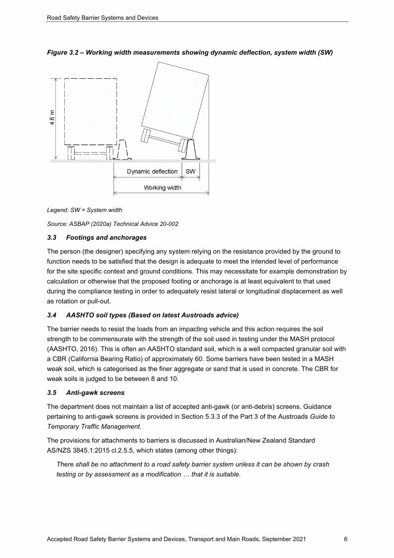
Working width from impacts into barriers should be used to identify the possible intrusion into the area behind a barrier. Working width is measured from the outermost extremity on the traffic side, regardless of shape, to the furthest extremity of any part of the system or vehicle during and after the impact. Designers are recommended to adopt the largest working width value for the nominated containment level based on crash testing as per the TMR 's accepted product datasheet or obtain from product owners.
Working width may also be determined following a site specific risk assessment based upon type and speed of vehicles on the adjacent roadway, and knowledge of the performance characteristics of the barrier.
Deflection values reported in this document are typically those reported during crash testing performed under controlled conditions. Designers should be cognisant of the type of hazard/s and the risk of vehicle and/or barrier intruding behind the barrier before deciding to use deflection value in lieu of working width. Designers are encouraged to check with product owners that these values are correct before proceeding to select site-specific design deflections. Designers need to be cognisant that the crash test deflection value is a single data point, and that in-service performance may be expected to vary.
For further information, see RPDM 2nd Edition Volume 3 Part 6 (QTMR, 2014) section 6.3.15 to 6.3.17 and associated text in the Guide to Road Design Part 6 (Austroads, 2009). Further guidance is also provided in the Guidelines for Road Design on Brownfield Sites (TMR, 2013)
Typical working width measurements are illustrated in Figure 3.2.
Road Safety Barrier Systems and Devices
Accepted Road Safety Barrier Systems and Devices, Transport and Main Roads, September 2021 6
Figure 3.2 – Working width measurements showing dynamic deflection, system width (SW)
Legend: SW = System width
Source: ASBAP (2020a) Technical Advice 20-002
3.3 Footings and anchorages
The person (the designer) specifying any system relying on the resistance provided by the ground to function needs to be satisfied that the design is adequate to meet the intended level of performance for the site specific context and ground conditions. This may necessitate for example demonstration by calculation or otherwise that the proposed footing or anchorage is at least equivalent to that used during the compliance testing in order to adequately resist lateral or longitudinal displacement as well as rotation or pull-out.
3.4 AASHTO soil types (Based on latest Austroads advice)
The barrier needs to resist the loads from an impacting vehicle and this action requires the soil strength to be commensurate with the strength of the soil used in testing under the MASH protocol (AASHTO, 2016). This is often an AASHTO standard soil, which is a well compacted granular soil with a CBR (California Bearing Ratio) of approximately 60. Some barriers have been tested in a MASH weak soil, which is categorised as the finer aggregate or sand that is used in concrete. The CBR for weak soils is judged to be between 8 and 10.
3.5 Anti-gawk screens
The department does not maintain a list of accepted anti-gawk (or anti-debris) screens. Guidance pertaining to anti-gawk screens is provided in Section 5.3.3 of the Part 3 of the Austroads Guide to Temporary Traffic Management.
The provisions for attachments to barriers is discussed in Australian/New Zealand Standard AS/NZS 3845.1:2015 cl.2.5.5, which states (among other things):
There shall be no attachment to a road safety barrier system unless it can be shown by crash testing or by assessment as a modification … that it is suitable.

Road Safety Barrier Systems and Devices
Accepted Road Safety Barrier Systems and Devices, Transport and Main Roads, September 2021 7
Anti-gawk screens are considered to be an attachment to a road safety barrier system and as such are subject to the above provisions of the Standard. Wherever full scale crash testing is not provided then assessment (as required by AS/NZS 3845.1:2015) is required. Such an assessment would need as a minimum to address among other things the provisions of AS/NZS 3845.1:2015 and MUTCD Part 3 Supplement s.3.16-1.
Thereafter, a second engineering assessment is required to determine whether any road safety barrier and associated anti-gawk screen is appropriate for use at a site-specific project location.
In any impact event, it is likely that some elements of the screen attachment will be displaced and will enter the workzone. Practitioners prescribing the use of anti-gawk screens should be cognisant of the consequent increase in risk to workers. Refer section 3.1.
3.6 Delineation
Nose delineation for road safety barrier terminals, including crash cushions should be provided in accordance with the Manual of Uniform Traffic Control Devices.
3.7 Standing Offer Arrangements
A Standing Offer Arrangement may exist for the supply to Transport and Main Roads projects of certain road safety barrier componentry and devices. Project Managers especially are advised to contact the department’s Chief Procurement Office for further advice in this regard.

Road Safety Barrier Systems and Devices
Accepted Road Safety Barrier Systems and Devices, Transport and Main Roads, September 2021 8
4 Accepted road safety barriers and devices
Public Domain Steel Safety Barrier Systems must not be used on new projects or installations within the departmental road network. This change aligns Queensland with other Australian states and territories and complies with AS/NZS 3845. An exception may be made where maintaining existing Public Domain Steel Safety Barrier Systems when repairs and replacements can be reasonably and readily undertaken (or if justified and certified by an RPEQ as an exception).
If a project was already financially approved, funded or commenced based on public domain steel products that were current at the time prior to 1st April 2021, there is no expectation that proprietary products have to be applied.
If a project is still in design, every effort should be made to provide MASH compliant barriers.
For further information on this change view the FAQs and Decision Tree.
4.1 Permanent
4.1.1 Longitudinal barriers
Single Slope Concrete Barrier Type: Concrete (rigid) Accepted Test Level: MASH TL-1 TL-2 TL-3 TL-4 TL-5 TL-6 NCHRP350 TL-1 TL-2 TL-3 TL-4 TL-5 TL-6 Registered Supplier: Public Domain Notes: Test Level subject to height and configuration. Refer to Departmental Standard Drawing 1468. THRIE beam (EXISTING INSTALLATIONS ONLY) Type: Steel beam Accepted Test Level: MASH Not rated NCHRP350 TL-1 TL-2 TL-3 TL-4 TL-5 TL-6 Registered Supplier: Public Domain Notes: Refer to various Departmental Standard Drawings. Used primarily in transitions.
MODIFIED THRIE beam (EXISTING INSTALLATIONS ONLY) Type: Steel beam Accepted Test Level: MASH Not rated NCHRP350 TL-1 TL-2 TL-3 TL-4 TL-5 TL-6 Registered Supplier: Public Domain Notes: Refer to various Departmental Standard Drawings. Uses notched blockout.

Road Safety Barrier Systems and Devices
Accepted Road Safety Barrier Systems and Devices, Transport and Main Roads, September 2021 9
W-beam (EXISTING INSTALLATIONS ONLY) Type: Steel beam Accepted Test Level: MASH Not rated NCHRP350 TL-1 TL-2 TL-3 TL-4 TL-5 TL-6 Registered Supplier: Public Domain Notes: Refer to various Departmental Standard Drawings.
Ezy-Guard 4 Type: Steel beam Accepted Test Level: MASH TL-1 TL-2 TL-3 TL-4 TL-5 TL-6 NCHRP350 TL-1 TL-2 TL-3 TL-4 TL-5 TL-6 Registered Supplier: Ingal Civil Products
Ezy-Guard SMART Type: Steel beam Accepted Test Level: MASH TL-1 TL-2 TL-3 TL-4 TL-5 TL-6 NCHRP350 Not rated. Registered Supplier: Ingal Civil Products
Ezy-Guard High Containment (HC) Type: Steel beam Accepted Test Level: MASH TL-1 TL-2 TL-3 TL-4 TL-5 TL-6 NCHRP350 Not rated. Registered Supplier: Ingal Civil Products
RAMSHIELD Type: Steel beam Accepted Test Level: MASH TL-1 TL-2 TL-3 TL-4 TL-5 TL-6 NCHRP350 Not rated. Registered Supplier: Safe Direction
Sentry W-beam Type: Steel beam Accepted Test Level: MASH TL-1 TL-2 TL-3 TL-4 TL-5 TL-6 NCHRP350 Not rated. Registered Supplier: Australian Construction Products Sentry Thrie-Beam Type: Steel beam Accepted Test Level: MASH TL-1 TL-2 TL-3 TL-4 TL-5 TL-6 NCHRP350 Not rated. Registered Supplier: Australian Construction Products

Road Safety Barrier Systems and Devices
Accepted Road Safety Barrier Systems and Devices, Transport and Main Roads, September 2021 10
Brifen 4-rope Type: Wire Rope Accepted Test Level: MASH Not rated. NCHRP350 TL-1 TL-2 TL-3 TL-4 TL-5 TL-6 Registered Supplier: Hill & Smith Notes: Brifen 4-rope requires Brifen End Anchor TL-3.
Brifen MASH TL-3 Type: Wire Rope Accepted Test Level: MASH TL-1 TL-2 TL-3 TL-4 TL-5 TL-6 NCHRP350 Not rated. Registered Supplier: Safe Direction Pty Ltd Notes: Brifen MASH TL3 requires Brifen MASH TL3 End Terminal. Flexfence 4-rope Type: Wire Rope Accepted Test Level: MASH Not rated. NCHRP350 TL-1 TL-2 TL-3 TL-4 TL-5 TL-6 Registered Supplier: Ingal Civil Products Notes: The TL-3 and TL-4 systems are different products. Flexfence 4-rope requires Flexfence End Anchor TL-3. MashFlex Type: Wire Rope Accepted Test Level: MASH TL-1 TL-2 TL-3 TL-4 TL-5 TL-6 NCHRP350 Not rated. Registered Supplier: Ingal Civil Products Notes: MashFlex requires MashFlex Terminal. Sentryline II 4-rope Type: Wire Rope Accepted Test Level: MASH Not rated. NCHRP350 TL-1 TL-2 TL-3 TL-4 TL-5 TL-6 Registered Supplier: Australian Construction Products Notes: Sentryline II 4-rope requires Sentryline II End Anchor TL-3.
Sentryline-M Type: Wire Rope Accepted Test Level: MASH TL-1 TL-2 TL-3 TL-4 TL-5 TL-6 NCHRP350 Not rated. Registered Supplier: Australian Construction Products Notes: Sentryline-M requires Sentryline-M Wire Rope Terminal End TL-3.

Road Safety Barrier Systems and Devices
Accepted Road Safety Barrier Systems and Devices, Transport and Main Roads, September 2021 11
4.1.2 End treatments
MELT (EXISTING INSTALLATIONS ONLY) Type: Gating (Redirective from 3rd Post) Accepted Test Level: MASH Not rated. NCHRP350 TL-1 TL-2 TL-3 TL-4 TL-5 TL-6 Registered Supplier: Public Domain Notes: Refer to Departmental Standard Drawing 1474 (withdrawn). Departure End Terminal (DET) (EXISTING INSTALLATIONS ONLY) Type: Gating (Redirective to penultimate post) MASH Not rated. NCHRP350 TL-1 TL-2 TL-3 TL-4 TL-5 TL-6 Registered Supplier: Public Domain Notes: Refer to Departmental Standard Drawing 1474 (withdrawn). “ACP” MELT (EXISTING INSTALLATIONS ONLY) Type: Gating (Redirective from 3rd Post) Accepted Test Level: MASH Not rated. NCHRP350 TL-1 TL-2 TL-3 TL-4 TL-5 TL-6 Registered Supplier: Australian Construction Products Notes: Flared, Parabolic; Non Energy Absorbing; X350 Post System and ACP plastic blockout. “INGAL” MELT (EXISTING INSTALLATIONS ONLY) Type: Gating (Redirective from 3rd Post) Accepted Test Level: MASH Not rated. NCHRP350 TL-1 TL-2 TL-3 TL-4 TL-5 TL-6 Registered Supplier: Ingal Civil Products Notes: Flared, Parabolic; Non Energy Absorbing; Steel Yielding Terminal Post System and Ingal plastic blockout.
ET2000 Plus Type: Gating (Redirective from 3rd Post) Accepted Test Level: MASH Not rated. NCHRP350 TL-1 TL-2 TL-3 TL-4 TL-5 TL-6 Registered Supplier: Ingal Civil Products Notes: Tangential/Flared; Extruder Head; TL-2 (7.6m - shorter length), TL-3 (15.2m - longer length). Accepted Variants: ET2000 Plus Motorcyclist Protection Shield (see below) ET2000 Plus Head Cover (see below)
ET2000 Plus Motorcyclist Protection Shield Type: Extruder Head Cover Accepted Test Level: MASH Not rated. NCHRP350 Not rated. Registered Supplier: Ingal Civil Products Notes: This component may be used where there is a relatively higher risk of motorcycle impact.
Road Safety Barrier Systems and Devices
Accepted Road Safety Barrier Systems and Devices, Transport and Main Roads, September 2021 12
ET2000 Plus Head Cover Type: Extruder Head Cover Accepted Test Level: MASH Not rated. NCHRP350 Not rated. Registered Supplier: Ingal Civil Products Notes: This component may be used where there is a relatively higher risk of motorcycle impact.
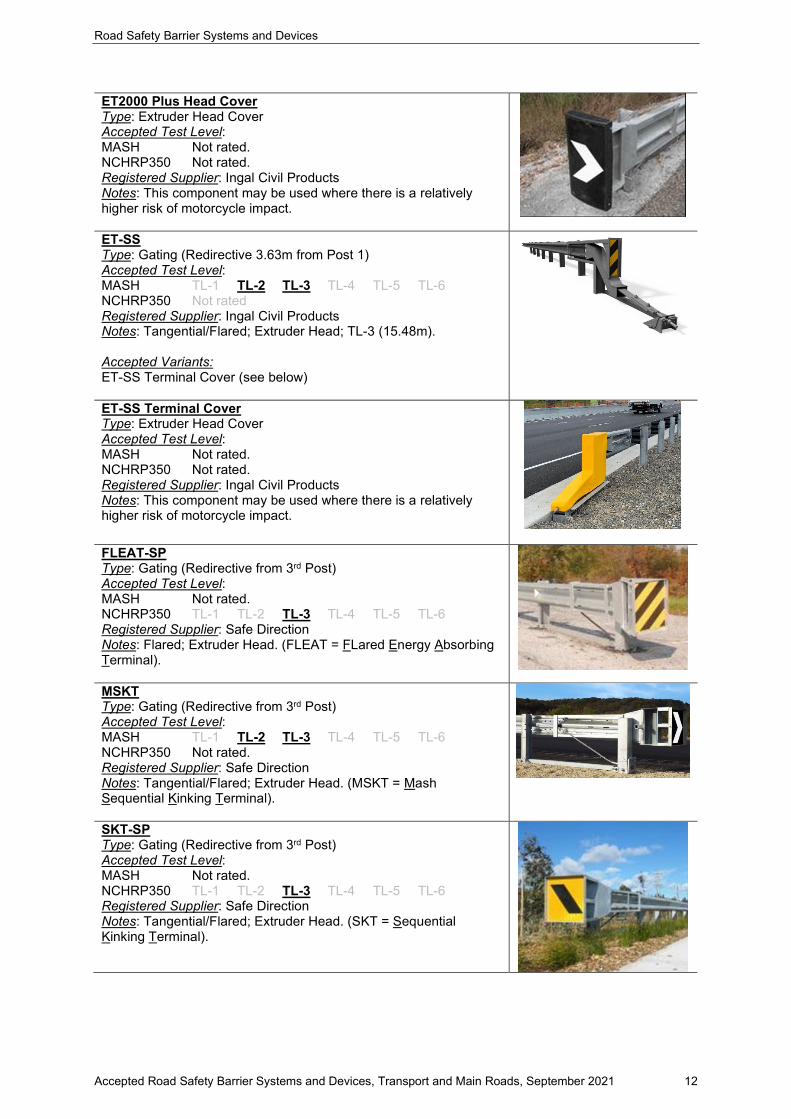
ET-SS Type: Gating (Redirective 3.63m from Post 1) Accepted Test Level: MASH TL-1 TL-2 TL-3 TL-4 TL-5 TL-6 NCHRP350 Not rated Registered Supplier: Ingal Civil Products Notes: Tangential/Flared; Extruder Head; TL-3 (15.48m). Accepted Variants: ET-SS Terminal Cover (see below)
ET-SS Terminal Cover Type: Extruder Head Cover Accepted Test Level: MASH Not rated. NCHRP350 Not rated. Registered Supplier: Ingal Civil Products Notes: This component may be used where there is a relatively higher risk of motorcycle impact.
FLEAT-SP Type: Gating (Redirective from 3rd Post) Accepted Test Level: MASH Not rated. NCHRP350 TL-1 TL-2 TL-3 TL-4 TL-5 TL-6 Registered Supplier: Safe Direction Notes: Flared; Extruder Head. (FLEAT = FLared Energy Absorbing Terminal).
MSKT Type: Gating (Redirective from 3rd Post) Accepted Test Level: MASH TL-1 TL-2 TL-3 TL-4 TL-5 TL-6 NCHRP350 Not rated. Registered Supplier: Safe Direction Notes: Tangential/Flared; Extruder Head. (MSKT = Mash Sequential Kinking Terminal).
SKT-SP Type: Gating (Redirective from 3rd Post) Accepted Test Level: MASH Not rated. NCHRP350 TL-1 TL-2 TL-3 TL-4 TL-5 TL-6 Registered Supplier: Safe Direction Notes: Tangential/Flared; Extruder Head. (SKT = Sequential Kinking Terminal).
Road Safety Barrier Systems and Devices
Accepted Road Safety Barrier Systems and Devices, Transport and Main Roads, September 2021 13
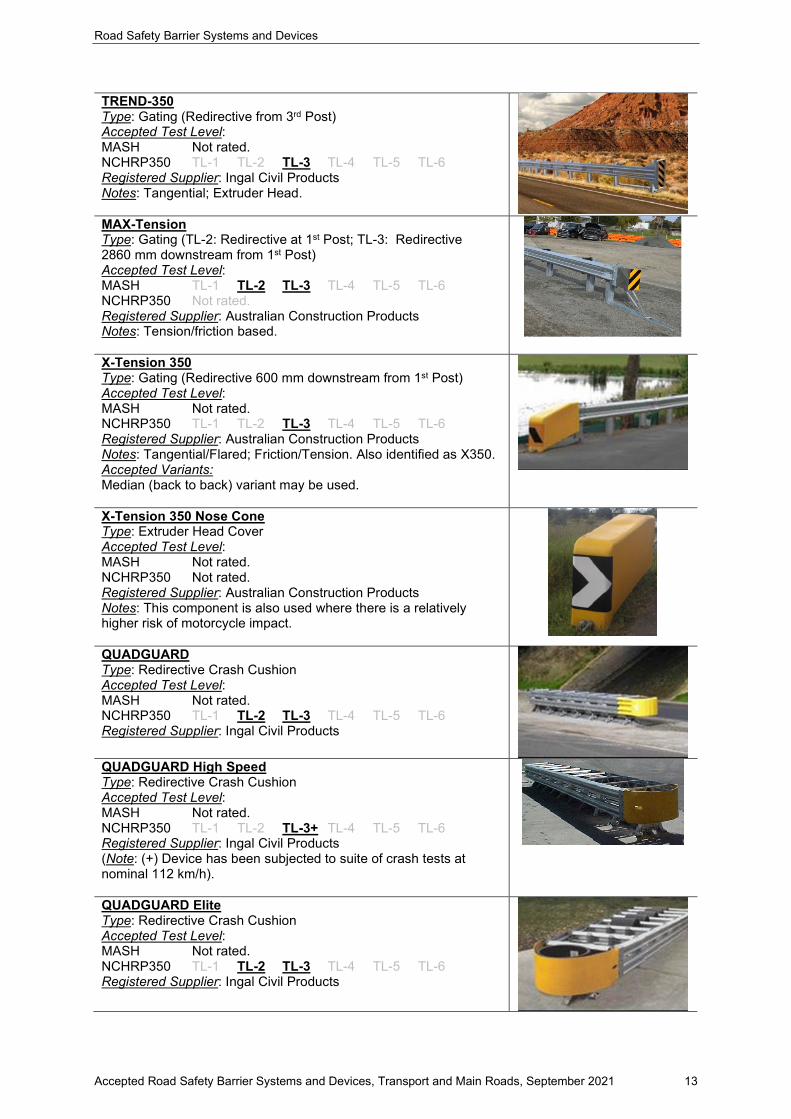
TREND-350 Type: Gating (Redirective from 3rd Post) Accepted Test Level: MASH Not rated. NCHRP350 TL-1 TL-2 TL-3 TL-4 TL-5 TL-6 Registered Supplier: Ingal Civil Products Notes: Tangential; Extruder Head. MAX-Tension Type: Gating (TL-2: Redirective at 1st Post; TL-3: Redirective 2860 mm downstream from 1st Post) Accepted Test Level: MASH TL-1 TL-2 TL-3 TL-4 TL-5 TL-6 NCHRP350 Not rated. Registered Supplier: Australian Construction Products Notes: Tension/friction based.
X-Tension 350 Type: Gating (Redirective 600 mm downstream from 1st Post) Accepted Test Level: MASH Not rated. NCHRP350 TL-1 TL-2 TL-3 TL-4 TL-5 TL-6 Registered Supplier: Australian Construction Products Notes: Tangential/Flared; Friction/Tension. Also identified as X350. Accepted Variants: Median (back to back) variant may be used.
X-Tension 350 Nose Cone Type: Extruder Head Cover Accepted Test Level: MASH Not rated. NCHRP350 Not rated. Registered Supplier: Australian Construction Products Notes: This component is also used where there is a relatively higher risk of motorcycle impact.
QUADGUARD Type: Redirective Crash Cushion Accepted Test Level: MASH Not rated. NCHRP350 TL-1 TL-2 TL-3 TL-4 TL-5 TL-6 Registered Supplier: Ingal Civil Products QUADGUARD High Speed Type: Redirective Crash Cushion Accepted Test Level: MASH Not rated. NCHRP350 TL-1 TL-2 TL-3+ TL-4 TL-5 TL-6 Registered Supplier: Ingal Civil Products (Note: (+) Device has been subjected to suite of crash tests at nominal 112 km/h).
QUADGUARD Elite Type: Redirective Crash Cushion Accepted Test Level: MASH Not rated. NCHRP350 TL-1 TL-2 TL-3 TL-4 TL-5 TL-6 Registered Supplier: Ingal Civil Products

Road Safety Barrier Systems and Devices
Accepted Road Safety Barrier Systems and Devices, Transport and Main Roads, September 2021 14
QUADGUARD M10 Type: Redirective Crash Cushion Accepted Test Level: MASH TL-1 TL-2 TL-3 TL-4 TL-5 TL-6 NCHRP350 Not rated. Registered Supplier: Ingal Civil Products
QUADGUARD Elite M10 Type: Redirective Crash Cushion Accepted Test Level: MASH TL-1 TL-2 TL-3 TL-4 TL-5 TL-6 NCHRP350 Not rated. Registered Supplier: Ingal Civil Products
Smart Cushion Type: Redirective Crash Cushion Accepted Test Level: MASH TL-1 TL-2 TL-3 TL-4 TL-5 TL-6 NCHRP350 TL-1 TL-2 TL-3 TL-4 TL-5 TL-6 Registered Supplier: LB Australia Accepted Variants: SCI100GM (MASH TL-3, NCHRP350 TL-3) SCI70GM (NCHRP350 TL-2)
TRACC Type: Redirective Crash Cushion Accepted Test Level: MASH Not rated. NCHRP350 TL-1 TL-2 TL-3 TL-4 TL-5 TL-6 Registered Supplier: Ingal Civil Products
Universal TAU II Type: Redirective Crash Cushion Accepted Test Level: MASH Not rated. NCHRP350 TL-1 TL-2 TL-3 TL-4 TL-5 TL-6 Registered Supplier: Australian Construction Products
Universal TAU-M Type: Redirective Crash Cushion Accepted Test Level: MASH TL-1 TL-2 TL-3 TL-4 TL-5 TL-6 NCHRP350 Not rated. Registered Supplier: Australian Construction Products
Thrie-beam Bullnose (EXISTING INSTALLATIONS ONLY) Type: Non-redirective system Accepted Test Level: MASH Not rated. NCHRP350 TL-1 TL-2 TL-3 TL-4 TL-5 TL-6 Registered Supplier: Public Domain Notes: Departmental Standard Drawing 1488 (withdrawn). Hazard free zone required.

Road Safety Barrier Systems and Devices
Accepted Road Safety Barrier Systems and Devices, Transport and Main Roads, September 2021 15
4.2 Temporary
4.2.1 Longitudinal barriers
Precast Concrete Barrier (PCB) Type: Temporary Concrete Barrier – Single Slope Accepted Test Level: MASH Not rated. NCHRP350 TL-1 TL-2 TL-3 TL-4 TL-5 TL-6 Registered Supplier: Public Domain Notes: Departmental Standard Drawings 1473 and 1458. Has a permanent configuration option, refer TMR SD1473. Photo shows example of anti-gawk screen attached. DB80 K150 Precast Concrete Barrier Type: Temporary Concrete Barrier – F Shape Accepted Test Level: MASH TL-1 TL-2 TL-3 TL-4 TL-5 TL-6 NCHRP350 TL-1 TL-2 TL-3 TL-4 TL-5 TL-6 EN1317 N1 N2 H1 H2 H3 H4a H4b Registered Supplier: Orange Hire Notes: This F shape temporary concrete barrier is only acceptable for use on roads with speed limits of 80 km/h or less. Accepted Variants: 4m units are MASH TL-3 6m units are EN1317-2 H1
JJ-Hooks Precast Concrete Barrier Type: Temporary Concrete Barrier – F Shape Accepted Test Level: MASH TL-1 TL-2 TL-3 TL-4 TL-5 TL-6 NCHRP350 TL-1 TL-2 TL-3 TL-4 TL-5 TL-6 Registered Supplier: Australian Road Barriers Notes: This F shape temporary concrete barrier is acceptable for use only on roads with speed limits of 80 km/h or less.
JJ Hooks MASH Precast Concrete Barrier Type: Temporary Concrete Barrier – F Shape Accepted Test Level: MASH TL-1 TL-2 TL-3 TL-4 TL-5 TL-6 NCHRP350 Not rated Registered Supplier: Australian Road Barriers Notes: This F shape temporary concrete barrier is acceptable for use only on roads with speed limits of 80 km/h or less.
T-LOK Precast Concrete Barrier Type: Temporary Concrete Barrier – F Shape Accepted Test Level: MASH TL-1 TL-2 TL-3 TL-4 TL-5 TL-6 NCHRP350 TL-1 TL-2 TL-3 TL-4 TL-5 TL-6 Registered Supplier: Saferoads Notes: This F shape temporary concrete barrier is acceptable for use only on roads with speed limits of 80 km/h or less. Accepted Variants: T-Lok 350 (NCHRP350 TL-3) T-Lok MASH (MASH TL-3)

Road Safety Barrier Systems and Devices
Accepted Road Safety Barrier Systems and Devices, Transport and Main Roads, September 2021 16
Pin and Loop Precast Concrete Barrier Type: Temporary Concrete Barrier – F Shape Accepted Test Level: MASH TL-1 TL-2 TL-3 TL-4 TL-5 TL-6 NCHRP350 Not rated Registered Supplier: Pin and Loop Pty Ltd Notes: This F shape temporary concrete barrier is acceptable for use only on roads with speed limits of 80 km/h or less.
BG800 Type: Temporary Steel Barrier Accepted Test Level: MASH TL-1 TL-2 TL-3 TL-4 TL-5 TL-6 NCHRP350 TL-1 TL-2 TL-3 TL-4 TL-5 TL-6 Registered Supplier: Ingal Civil Products Notes: Suite of products include Standard, MDS (Minimum Deflection System), and LDS (Limited Deflection System). Accepted Variants: BG800 Standard (NCHRP350 TL-2, TL-3, TL-4; MASH TL-3) BG800 MDS (NCHRP350 TL-3) BG800 LDS (NCHRP350 TL-3 and TL-4)
HighwayGuard Type: Temporary Steel Barrier Accepted Test Level: MASH TL-1 TL-2 TL-3 TL-4 TL-5 TL-6 NCHRP350 TL-1 TL-2 TL-3 TL-4 TL-5 TL-6 Registered Supplier: Ingal Civil Products Notes: Suite of products include HighwayGuard LDS (Lowest Deflection System) and Temporary. Accepted Variants: HighwayGuard LDS (MASH TL-3) HighwayGuard Temporary (MASH TL-3 and TL-4)
Defender Barrier Type: Temporary Steel Barrier Accepted Test Level: MASH TL-1 TL-2 TL-3 TL-4 TL-5 TL-6 NCHRP350 TL-1 TL-2 TL-3 TL-4 TL-5 TL-6 Registered Supplier: Safe Barriers Pty. Ltd. Notes: Suite of products include Defender Barrier 70, 100 LDS (Limited Deflection System), and 100 HC (High Containment). Accepted Variants: Defender Barrier 70 Defender Barrier 100 LDS Defender Barrier 100 HC Defender Barrier 100 FS
SafeZone Type: Temporary Steel Barrier Accepted Test Level: MASH TL-1 TL-2 TL-3 TL-4 TL-5 TL-6 NCHRP350 TL-1 TL-2 TL-3 TL-4 TL-5 TL-6 Registered Supplier: Australian Construction Products Notes: Suite of products include Standard and LDS (Limited Deflection System). Accepted Variants: SafeZone Standard (MASH TL-3 and TL-4) SafeZone LDS (MASH TL-3 and TL-4)

Road Safety Barrier Systems and Devices
Accepted Road Safety Barrier Systems and Devices, Transport and Main Roads, September 2021 17
IronMan Type: Temporary Steel Barrier Accepted Test Level: MASH TL-1 TL-2 TL-3 TL-4 TL-5 TL-6 NCHRP350 TL-1 TL-2 TL-3 TL-4 TL-5 TL-6 Registered Supplier: Saferoads Notes: There are a number of variants of Ironman. Refer to data sheet and consult supplier. Speed restrictions apply to some variants. Accepted Variants: IronMan Original IronMan Heavy Duty IronMan Hybrid
Zoneguard Type: Temporary Steel Barrier Accepted Test Level: MASH TL-1 TL-2 TL-3 TL-4 TL-5 TL-6 NCHRP350 TL-1 TL-2 TL-3 TL-4 TL-5 TL-6 Registered Supplier: Hill & Smith Notes: Minimum Deflection System’ available at TL-3. Accepted Variants: Zoneguard (NCHRP350 TL-4, MASH TL-3) Zoneguard ‘Minimum Deflection System’ (MASH TL-3)
HV2 Type: Temporary Steel Barrier Accepted Test Level: MASH TL-1 TL-2 TL-3 TL-4 TL-5 TL-6 NCHRP350 TL-1 TL-2 TL-3 TL-4 TL-5 TL-6 Registered Supplier: Saferoads Pty Ltd Notes: The longitudinal barrier test was done on a concrete surface, and transition test on an asphalt surface.
ArmorZone MASH Type: Temporary Plastic Water Filled Device Accepted Test Level: MASH TL-1 TL-2 TL-3 TL-4 TL-5 TL-6 NCHRP350 TL-1 TL-2 TL-3 TL-4 TL-5 TL-6 Registered Supplier: Ingal Civil Products Notes: ArmorZone MASH units must not be mixed with ArmorZone NCHRP350 units.
ArmorZone (NCHRP350) Type: Temporary Plastic Water Filled Device Accepted Test Level: MASH TL-1 TL-2 TL-3 TL-4 TL-5 TL-6 NCHRP350 TL-1 TL-2 TL-3 TL-4 TL-5 TL-6 Registered Supplier: Ingal Civil Products Notes: Water-filled temporary barrier for use in work zones where posted speed ≤ 50 km/h. May, subject to detailed site‐specific risk assessment, be used to shield worksites where the posted speed does not exceed 70 km/h. ArmorZone (NCHRP350) units must not be mixed with ArmorZone MASH units.

Road Safety Barrier Systems and Devices
Accepted Road Safety Barrier Systems and Devices, Transport and Main Roads, September 2021 18
Ricochet Type: Temporary Plastic Water Filled Device Accepted Test Level: MASH TL-1 TL-2 TL-3 TL-4 TL-5 TL-6 NCHRP350 TL-1 TL-2 TL-3 TL-4 TL-5 TL-6 Registered Supplier: TFH Hire Services Notes: Water-filled temporary barrier for use in work zones where posted speed ≤ 50 km/h. Lo-Ro Water Cable Barrier Type: Temporary Plastic Water Filled Device Accepted Test Level: MASH TL-1 TL-2 TL-3 TL-4 TL-5 TL-6 NCHRP350 TL-1 TL-2 TL-3 TL-4 TL-5 TL-6 Registered Supplier: Jaybro Group Pty Ltd Notes: Water-filled temporary barrier for use in work zones where posted speed ≤ 70 km/h.
Shield I Type: Temporary Plastic Water Filled Device Accepted Test Level: MASH TL-1 TL-2 TL-3 TL-4 TL-5 TL-6 NCHRP350 TL-1 TL-2 TL-3 TL-4 TL-5 TL-6 Registered Supplier: National Plastic Group Notes: Water-filled temporary barrier for use in work zones where posted speed ≤ 50 km/h.
Triton (TL-1 variant) Type: Temporary Plastic Water Filled Device (with internal steel frame) Accepted Test Level: MASH TL-1 TL-2 TL-3 TL-4 TL-5 TL-6 NCHRP350 TL-1 TL-2 TL-3 TL-4 TL-5 TL-6 Registered Supplier: Ingal Civil Products Notes: Internal steel frame. Water-filled temporary barrier for use in work zones where posted speed ≤ 50 km/h. May, subject to detailed site‐specific risk assessment, be used to shield worksites where the posted speed does not exceed 70 km/h.
Mobile Barriers MBT-1 Type: Temporary Workzone Protection Device Accepted Test Level: MASH TL-1 TL-2 TL-3 TL-4 TL-5 TL-6 NCHRP350 TL-1 TL-2 TL-3 TL-4 TL-5 TL-6 Registered Supplier: Mobile Barriers
4.2.2 End treatments
Some permanent crash cushions as listed above may be suitable for connection to temporary barrier systems. Designer should consult system supplier to verify compatibility between systems.
Absorb 350 Type: Non-Redirective, Gating Plastic Water Filled Crash Cushion Accepted Test Level: MASH TL-1 TL-2 TL-3 TL-4 TL-5 TL-6 NCHRP350 TL-1 TL-2 TL-3 TL-4 TL-5 TL-6 Registered Supplier: Australian Construction Products

Road Safety Barrier Systems and Devices
Accepted Road Safety Barrier Systems and Devices, Transport and Main Roads, September 2021 19
Notes: Limited to ≤ 70 km/hr. May be used in higher speed environments subject to site-specific risk assessment noting that product may only be used where high speed side impacts are unlikely, penetration behind the barrier is acceptable and use of a redirecting impact attenuator is not feasible for reasons other than cost or convenience. Note that configuration (length/no. of units) changes with impact speed rating. Absorb-M Type: Water Filled, Non-Redirective, Gating Plastic Terminal Accepted Test Level: MASH TL-1 TL-2 TL-3 TL-4 TL-5 TL-6 NCHRP350 Not rated. Registered Supplier: Australian Construction Products Notes: 3-Unit System: Limited to ≤ 80 km/hr; 2-Unit System: Limited to ≤ 60 km/hr.
TRITON Concrete End Terminal (CET) Type: Non-Redirective, Gating Plastic Water Filled Crash Cushion Accepted Test Level: MASH TL-1 TL-2 TL-3 TL-4 TL-5 TL-6 NCHRP350 TL-1 TL-2 TL-3 TL-4 TL-5 TL-6 Registered Supplier: Ingal Civil Products Notes: Limited to ≤ 70 km/hr. May be used in higher speed environments subject to site-specific risk assessment noting that product may only be used where high speed side impacts are unlikely, penetration behind the barrier is acceptable and use of a redirecting impact attenuator is not feasible for reasons other than cost or convenience. Note that configuration changes with impact speed rating, NSW, must be installed on pedestals where speed >70 km/h.
SLED Type: Non-Redirective, Gating Plastic Water Filled Crash Cushion Accepted Test Level: MASH TL-1 TL-2 TL-3 TL-4 TL-5 TL-6 NCHRP350 TL-1 TL-2 TL-3 TL-4 TL-5 TL-6 Registered Supplier: Saferoads Pty Ltd Notes: Limited to ≤ 80 km/hr both during and outside work hours.
4.3 Other road safety devices
4.3.1 Gates
ARMORGUARD Gate Type: Gate Accepted Test Level: MASH TL-1 TL-2 TL-3 TL-4 TL-5 TL-6 NCHRP350 TL-1 TL-2 TL-3 TL-4 TL-5 TL-6 Registered Supplier: Australian Construction Products
Road Safety Barrier Systems and Devices
Accepted Road Safety Barrier Systems and Devices, Transport and Main Roads, September 2021 20
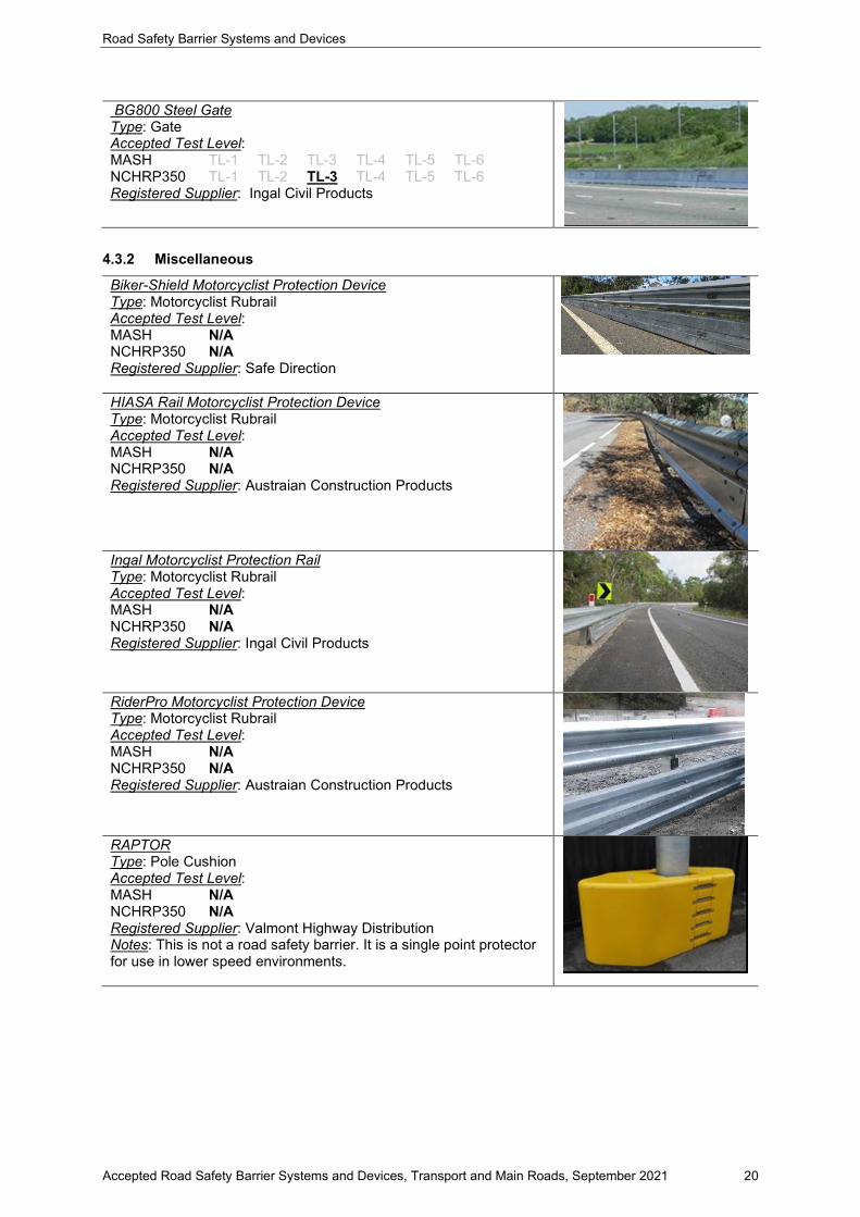
BG800 Steel Gate Type: Gate Accepted Test Level: MASH TL-1 TL-2 TL-3 TL-4 TL-5 TL-6 NCHRP350 TL-1 TL-2 TL-3 TL-4 TL-5 TL-6 Registered Supplier: Ingal Civil Products
4.3.2 Miscellaneous
Biker-Shield Motorcyclist Protection Device Type: Motorcyclist Rubrail Accepted Test Level: MASH N/A NCHRP350 N/A Registered Supplier: Safe Direction
HIASA Rail Motorcyclist Protection Device Type: Motorcyclist Rubrail Accepted Test Level: MASH N/A NCHRP350 N/A Registered Supplier: Austraian Construction Products
Ingal Motorcyclist Protection Rail Type: Motorcyclist Rubrail Accepted Test Level: MASH N/A NCHRP350 N/A Registered Supplier: Ingal Civil Products
RiderPro Motorcyclist Protection Device Type: Motorcyclist Rubrail Accepted Test Level: MASH N/A NCHRP350 N/A Registered Supplier: Austraian Construction Products
RAPTOR Type: Pole Cushion Accepted Test Level: MASH N/A NCHRP350 N/A Registered Supplier: Valmont Highway Distribution Notes: This is not a road safety barrier. It is a single point protector for use in lower speed environments.

Road Safety Barrier Systems and Devices
Accepted Road Safety Barrier Systems and Devices, Transport and Main Roads, September 2021 21
“ACP” Plastic Blockout Type: Blockout Accepted Test Level: MASH N/A NCHRP350 N/A Registered Supplier: Australian Construction Products Notes: For use in selected terminals only. Approval for use of plastic blocks on Public Domain W-beam guardrail strong posts was withdrawn in March 2008. Plastic blocks remain accepted for use in respective proprietary terminals. Designer to consult with supplier.
No picture
“Ingal” Plastic Blockout Type: Blockout Accepted Test Level: MASH N/A NCHRP350 N/A Registered Supplier: Ingal Civil Products Notes: For use in selected terminals only. Approval for use of plastic blocks on Public Domain W-beam guardrail strong posts was withdrawn in March 2008. Plastic blocks remain accepted for use in respective proprietary terminals. Designer to consult with supplier.
No picture
Road Safety Barrier Systems and Devices
Accepted Road Safety Barrier Systems and Devices, Transport and Main Roads, September 2021 22
5 Assessed by ASBAP in Accordance with AS/NZS 3845.2:2017
The products in this list have been assessed and accepted by ASBAP in accordance with AS/NZS 3845.2:2017. Products listed here have only been assessed in accordance with AS/NZS3845.2:2017, and there are other approvals that are required elsewhere in the Department or in other external agencies prior to use. In other words, a product listed here is not approved for use, but approved for its assessment in accordance with AS/NZS3845.2:2017 only.
In summary, among other things, AS/NZS3845.2:2017 primarily only assesses a products suitability from a crashworthiness perspective. Any other aspects of a product are not specifically reviewed by ASBAP.
Product Information Sheets (within the Appendix B) are not produced for these products.
Important Notes:
1. ASBAP have stated that after 31 December 2020, AS/NZS 3845.2:2017 type products should be assessed under MASH protocols.
2. Prior to 31 December 2020, crashworthiness may be demonstrated via crash testing to other protocols (for example, NCHRP350).
3. Operators are advised that over time, the list below will be populated as more products are submitted to ASBAP and assessed by ASBAP. Operators are recommended to be cognisant that the ASBAP assessment process may take considerable time, and they should continue with ‘business as usual’ arrangements.
4. Products not listed below may still be operationally acceptable to TMR under existing or future arrangements.
5. It is NOT the intention of the list below to imply that other products are not acceptable for use by TMR and cannot be used operationally by TMR.
6. Operators are recommended to select devices which are fit for purpose to their total requirements. Crashworthiness is just one aspect to consider.
7. Operators are recommended to select products that are suitable to their business needs. The evolving list below may be used as a guide in this regard.
5.1 Longitudinal Channelizing Devices
Nil
5.2 Truck and Trailer Mounted Attenuators
BLADE Type: Truck Mounted Attenuator Accepted Test Level: MASH TL-1 TL-2 TL-3 TL-4 TL-5 TL-6 NCHRP350 TL-1 TL-2 TL-3 TL-4 TL-5 TL-6 Registered Supplier: Innov8 Equipment Pty Ltd

Road Safety Barrier Systems and Devices
Accepted Road Safety Barrier Systems and Devices, Transport and Main Roads, September 2021 23
JL-D-0850 Stuer-Egghe “Julietta” Type: Truck Mounted Attenuator Accepted Test Level: MASH TL-1 TL-2 TL-3 TL-4 TL-5 TL-6 NCHRP350 TL-1 TL-2 TL-3 TL-4 TL-5 TL-6 Registered Supplier: J1-LED
Scorpion II Type 1: Truck Mounted Attenuator Accepted Test Level: MASH TL-1 TL-2 TL-3 TL-4 TL-5 TL-6 NCHRP350 TL-1 TL-2 TL-3 TL-4 TL-5 TL-6 Type 2: Truck Mounted Attenuator Accepted Test Level: MASH TL-1 TL-2 TL-3 TL-4 TL-5 TL-6 NCHRP350 TL-1 TL-2 TL-3 TL-4 TL-5 TL-6 Type 3: Trailer Mounted Attenuator Accepted Test Level: MASH TL-1 TL-2 TL-3 TL-4 TL-5 TL-6 NCHRP350 TL-1 TL-2 TL-3 TL-4 TL-5 TL-6 Registered Supplier: A1 Roadlines Pty Ltd
SS180M Type: Truck Mounted Attenuator Accepted Test Level: MASH TL-1 TL-2 TL-3 TL-4 TL-5 TL-6 NCHRP350 TL-1 TL-2 TL-3 TL-4 TL-5 TL-6 Registered Supplier: Ingal Civil Products
5.3 Rear Underrun Protection Devices
Nil
5.4 Permanent Bollards
Nil
5.5 Sign Support Structures and Poles
Nil

Road Safety Barrier Systems and Devices
Accepted Road Safety Barrier Systems and Devices, Transport and Main Roads, September 2021 24
Appendix A – Proprietors, suppliers and industry contacts
(Subject to change without notice)
A1 Roadlines Pty Ltd 89 Rushdale Street, Knoxfield, VIC 3180 Ph: 03 9765 9400 Mob: 0407 555 101 www.a1roadlines.com.au Contact: Janine Bartholomew Email: [email protected]
Advantage Plastics 254 Easterbrook Road, RD1 Kaiapoi 7691, NZ Ph: 0800 668 534 Mob: 021 228 5284 www.advantageplastics.co.nz Contact: David Hickmott Email: [email protected]
Australian Construction Products (ACP)
Unit 3/55 Christensen Road, Stapylton, QLD 4207 Ph: 07 3442 6200 Mob: 0434 605 109 www.acprod.com.au Contact: Nicholas Hassan Email: [email protected]
Australian Road Barriers RMB H535, Old Creswick Rd, Ballarat, VIC 3352 Ph: 1800 003 826 Fax: (03) 5339 9273 www.roadbarriers.com.au Contact: Ben Sexton Email: [email protected]
Highway Care International The Highlands, Detling, Maidstone, Kent, ME14 3HT, United Kingdom www.highwaycareint.com
Hill & Smith 1/242 New Cleveland Rd, Tingalpa, QLD 4173 Ph: 1300 277 683 www.hsroads.com.au Contact: Warwick Weeks Email: [email protected]
Ingal Civil Products 7 Nestor Drive, Meadowbrook, QLD 4131 Ph: 07 3489 9120 Fax: 07 3489 9130 www.ingalcivil.com.au Contact: Brett Wells Email: [email protected]
Innov8 Equipment Pty Ltd 86 Mulgoa Road Penrith NSW 2750 Ph: 1300 071 007 www.innov8equipmwent.com.au Contact: Tim Eato Email: [email protected]
Jaybro Group Pty Ltd 29 Penelope Crescent, Arndell Park, NSW 2148 Ph: 1300 885 364 www.jaybro.com.au Contact: Ben Lorne [email protected]

Road Safety Barrier Systems and Devices
Accepted Road Safety Barrier Systems and Devices, Transport and Main Roads, September 2021 25
J1-LED 10 Production Street, Beenleigh QLD 4207 Ph: 0405693911 www.j1led.com Contact: Shane Kelly Email: [email protected]
Laura Metaal Road Safety PTY Limited
L11 1 Margaret street, Sydney, NSW 2000 Ph: 0426360675 www.laurametaal.com Contact: Onno van den Toorn Email: [email protected]
LB Australia Unit 6/79, Mandoon Road, Girraween, NSW 2145 Ph: (02) 9631 8833 Fax: (02) 9688 4503 www.lbaustralia.com.au Contact: Paul Hansen Email: [email protected]
Mobile Barriers 24918 Genesee Trail Road, Golden, Colorado 80401, USA. Ph: 0432 931 981 http://int.mobilebarriers.com/ Contact: Ben Eizenberg Email: [email protected]
National Plastic Group 22 Christensen Road, Staplyton QLD 4207 Ph: 07 3807 0055 Fax: 07 3807 2315 www.nationalplasticsgroup.com.au Contact: Nina Adcock Email [email protected]
Orange Hire 71 Lavarack Ave, Eagle Farm, QLD 4009 www.orangehire.com.au
Pin and Loop Pty Ltd 63-69 High Street Queanbeyan NSW 2620 Ph: (02) 6297 1611 www.precastconcrete.com.au
Saferoads 22 Commercial Drive, Pakenham, VIC. 3810 Ph: 1800 060 072 www.saferoads.com.au Contact: Casey McMaster Email: [email protected]
Safe Direction 47 Telford Circuit, Yatala, QLD 4207 Ph: 1300 063 220 www.safedirection.com.au Contact: Terry Colquhoun Email: [email protected]
Safe Barriers PO Box 7178, Hemmant, QLD 4174 Ph: 1800 169 799 www.safebarriers.com Contact: David Moule Email: [email protected]
Road Safety Barrier Systems and Devices
Accepted Road Safety Barrier Systems and Devices, Transport and Main Roads, September 2021 26
Valmont Highway Distribution 57-65 Airds Road, Minto, NSW 2566 Ph: 02 9814 1711 www.valmonthighway.com Contact: Leigh Brown Email: [email protected]
TFH Hire Services 8-14 Eurora Street, Kingston, QLD 4114 Ph: 07 3299 2211 Contact: Michael Quinn Email: [email protected]

Road Safety Barrier Systems and Devices
Accepted Road Safety Barrier Systems and Devices, Transport and Main Roads, September 2021 27
Appendix B – Product information sheets
(Information Only)
1. Single Slope Concrete Barrier
2. Ezy-Guard 4
3. Ezy-Guard SMART
4. Ezy-Guard High Containment (HC)
5. RAMSHIELD
6. Sentry W-beam
7. Sentry Thrie-Beam
8. BRIFEN 4-rope TL-4
9. BRIFEN MASH TL3
10. Flexfence 4-rope TL-4 (and TL-3 configuration)
11. MashFlex
12. SENTRYLINE II 4-rope TL-4
13. SENTRYLINE-M
14. ET2000-Plus
15. ET-SS
16. FLEAT-SP
17. MSKT
18. SKT-SP
19. TREND-350
20. MAX-Tension
21. X-Tension 350
22. QUADGUARD
23. QUADGUARD High Speed
24. QUADGUARD ELITE
25. QUADGUARD M10
26. QUADGUARD Elite M10
27. SMART Cushion
28. TRACC
29. Universal TAU II
30. Universal TAU-M
31. Precast Concrete Barrier (PCB)
32. DB80 K150 Precast Concrete Barrier
33. J-J Hooks
34. JJ Hooks MASH
35. T-LOK
36. Pin and Loop
37. BarrierGuard 800
38. HighwayGuard
39. Defender Barrier
40. Ironman
41. SafeZone
42. Zoneguard
43. HV2
44. ArmorZone MASH
45. Armorzone (NCHRP350)
46. Ricochet
47. Lo-Ro Water Cable Barrier
48. Shield I
49. Triton
50. Mobile Barriers MBT-1
51. Absorb 350
52. Absorb-M
53. Triton Concrete End Terminal (CET)
54. SLED
55. Armorguard Gate
56. BarrierGuard 800 Steel Gate
57. Biker-Shield Motorcyclist Protection Device
58. Hiasa Rail Motorcyclist Protection Device
59. Ingal MPR

Road Safety Barrier Systems and Devices
Accepted Road Safety Barrier Systems and Devices, Transport and Main Roads, September 2021 28
60. RiderPro Motorcyclist Protection Device
61. Raptor

Single Slope Concrete BarrierTMR Standard Drawing 1468
Category: Longitudinal
Permanent/Temporary: Permanent
Introduction:The single slope barrier is a rigid extruded reinforced concrete barrier with a 10.8° profile. Heights may vary. AASHTO Roadside Design Guide (2011) (section 6.4.1.8) states "Concrete barrier shapes that meet the NCHRP Report 350 criteria are the New Jersey and F-shapes, the single-slope barrier (two variations in slope), and the vertical wall. These shapes, when adequately designed and reinforced may all be considered TL-4 designs at the standard height of 813mm and TL-5 designs at heights of 1067mm and higher”. An advantage of the single slope shape is that it can accommodate adjacent overlays without compromising the profile of the barrier. However, designers do need to be cognisant that overlays will reduce the effective height of the barrier and hence reduce its overall containment capacity.
Ownership:Public Domain
Supplier:Public Domain
Page 1 of 2
Test Level:Extruded Variant Deemed to meet NCHRP 350 TL-5 (1100mm high, anchored) (based on AASHTO Roadside Design Guide (2011) and FHWA memorandum HMHS-B64 dt. 14-Feb-2000). Refer to TMR Standard Drawing 1468 for further guidance on containment level. PCB: Pre-cast variant Refer to Precast Concrete Barrier (PCB) data sheet Permanent configurations for PCB shown on TMR
Standard Drawing 1473
Status*: Accepted
Status Commencement Date: Not Set
Status Expiry Date*: Not Set
* TMR reserves the right to alter the Status and Status Expiry Date at any time. Always refer to latest version of TMR's Road Safety Barrier Systems and End Treatments document.
Gating/Non-Gating: Not Applicable
Redirective/Non-Redirective: Redirective
Main Material: Concrete
Sub Category: Rigid
This information sheet shall be, where relevant, read in conjunction with the manufacturer's latest manual.Road Safety Barrier Systems and End Treatments: Product Information Sheet
Department of Transport and Main Roads
3:57 PMTuesday, 31 August 2021Created:
Recommended End Treatments:Any accepted permanent crash cushion (refer this document), with appropriate transition/connection. Alternatively, it is acceptable to transition to steel-beam barrier end terminal via transition (see TMR standard drawings).
Design:Standard configurations of single slope extruded barrier are provided on TMR Standard Drawing 1468. Whilst TMR Standard Drawing 1468 nominates the single slope barrier as a median barrier, it may be used at other locations. In order to maintain the specified containment capacity, adequate footing restraint must be provided to resist overturning and lateral deflection. The minimum lengths of barrier nominated on TMR Standard Drawing 1468 apply to lengths between gaps provided for street lighting and/or expansion joints. Where there is a risk that the end of a concrete barrier can be impacted, the end must be shielded by one of: (i) an accepted connection to another barrier system, (ii) a suitable method of overlap, (iii) an accepted crashworthy crash cushion. Overlays (or lift or corrector) courses placed after initial construction of the barrier may reduce the relative/residual height of barriers and/or their profile. Designers should make provision for such future treatments when designing a barrier.
Limitations:Refer to TMR Standard Drawing 1468. Designers and project managers should be cognisant that provision of lighting within barriers introduces some additional exposure to risk: (i) Street lighting poles are likely to exist within the working
width envelope. (ii) Steel cover plates shown on standard Drawing 1469 are
not expected to provide test level TL-5 containment capability.
Such design decisions should be documented in the design documentation.
Single Slope Concrete Barrier Page 2 of 2
References: AS/NZS 3845 NCHRP Report 350 TMR Road Planning and Design Manual Standard Drawing 1468 Roadside Design Guide (AASHTO, 2011) FHWA memorandum HMHS-B64 dt. 14-Feb-2000).
Deflection:Whilst this barrier type is “rigid” and should exhibit zero deflection under impact, designers should be cognisant of the possibility of vehicle roll and working width when locating objects mounted on or situated behind the barrier.
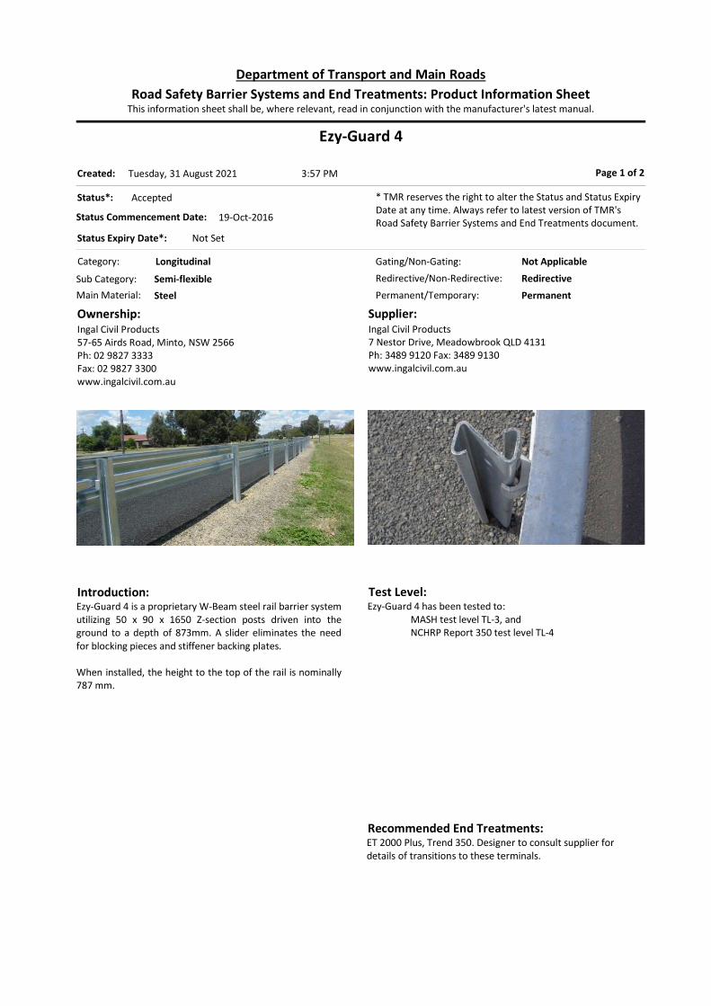
Ezy-Guard 4
Category: Longitudinal
Permanent/Temporary: Permanent
Introduction:Ezy-Guard 4 is a proprietary W-Beam steel rail barrier system utilizing 50 x 90 x 1650 Z-section posts driven into the ground to a depth of 873mm. A slider eliminates the need for blocking pieces and stiffener backing plates. When installed, the height to the top of the rail is nominally 787 mm.
Ownership:Ingal Civil Products57-65 Airds Road, Minto, NSW 2566Ph: 02 9827 3333Fax: 02 9827 3300www.ingalcivil.com.au
Supplier:Ingal Civil Products7 Nestor Drive, Meadowbrook QLD 4131Ph: 3489 9120 Fax: 3489 9130www.ingalcivil.com.au
Page 1 of 2
Test Level:Ezy-Guard 4 has been tested to:
MASH test level TL-3, and NCHRP Report 350 test level TL-4
Status*: Accepted
Status Commencement Date: 19-Oct-2016
Status Expiry Date*: Not Set
* TMR reserves the right to alter the Status and Status Expiry Date at any time. Always refer to latest version of TMR's Road Safety Barrier Systems and End Treatments document.
Gating/Non-Gating: Not Applicable
Redirective/Non-Redirective: Redirective
Main Material: Steel
Sub Category: Semi-flexible
This information sheet shall be, where relevant, read in conjunction with the manufacturer's latest manual.Road Safety Barrier Systems and End Treatments: Product Information Sheet
Department of Transport and Main Roads
3:57 PMTuesday, 31 August 2021Created:
Recommended End Treatments:ET 2000 Plus, Trend 350. Designer to consult supplier for details of transitions to these terminals.

Design:Product limitations, tolerances for installation, material specifications, etc. need to be furnished by the supplier. A back-to-back variant is accepted for median use. Designer should consult supplier on how to manage connections to terminals. Where posts cannot be installed to the required in-ground depth due to existence of underground features (e.g. drainage, PUP), posts may be replaced by base plate option. Refer to systems product manual for installation details. Designers to consult supplier for minimum length of barrier. Extended Design Domain: In instances where the road surface has been overlaid or resurfaced and the rail height is no longer within tolerances, a retrofittable carriage (called Ezy-Lift) with provision for height adjustment is accepted for use. Refer to systems product manual for installation details. Ezy-Lift is not accepted on the back-to-back variant of Ezy-Guard 4. Practitioners need to ensure that the lifted configuration is such that the top of rail remains higher than the top of the Ezy-Lift carriage. The preference is that the distance to the hinge point is sufficient to accommodate the design deflection. Placement of systems close to the hinge-point is discussed in the Guidelines for Road Design on Brownfield Sites document (section 5.1.13.1). Issues to consider are barrier performance (vehicle stability) and integrity of footings.
Limitations:All compliance testing is conducted in AASHTO standard soil. Refer to section 3.4 of this document. Consult with supplier when other conditions are encountered.
Ezy-Guard 4 Page 2 of 2
References: NCHRP Report 350 Manual for Assessing Safety Hardware (MASH) Austroads Conditions document (05 Sep 2017) Ingal Product Manual 08/17 Holmes Report 102350.97-5-3A (Mar 2011) Holmes Report 113003.00 (Dec 2014)
Holmes test no. 113004-310-1WB (4-Dec-2014) Ingal Civil Products Drawing No. EZY-SM-102
Deflection:Deflection (Normal Design Domain): Measured (Crash Test) Deflections and Working Widths:
Nominal Mass (kg)
Nominal Angle (deg)
Nominal Speed (km/h)
Recorded Deflection
(m)
Working Width
(m)
2,000 1 25 70 0.89 Obtain from
supplier
2,270 2 25 100 1.65 1.65
8,000 3 15 80 1.53 Obtain from
supplier
Notes: 1. NCHRP Report 350 TL-2 compliance testing on Ezy-Guard
SMART system. 2. MASH TL-3 compliance testing on Ezy-Guard SMART system 3. NCHRP Report 350 TL-4 compliance testing on Ezy-Guard 4
system.
Designers are recommended to adopt the largest working width / deflection value for the nominated containment level.

Ezy-Guard SMART
Category: Longitudinal
Permanent/Temporary: Permanent
Introduction:Ezy-Guard SMART is a proprietary W-Beam steel rail barrier system utilizing 50 x 90 x 1600 Z-section posts driven into the ground to a depth of 880 mm. A slider eliminates the need for blocking pieces and stiffener backing plates. When installed, the height to the top of the rail is nominally 730 mm and the top of the post is nominally 720 mm.
Ownership:Ingal Civil Products57-65 Airds Road, Minto, NSW 2566Ph: 02 9827 3333Fax: 02 9827 3300www.ingalcivil.com.au
Supplier:Ingal Civil Products7 Nestor Drive, Meadowbrook QLD 4131Ph: 3489 9120 Fax: 3489 9130www.ingalcivil.com.au
Page 1 of 2
Test Level:Ezy-Guard SMART has been tested to MASH test level TL-3.
Status*: Accepted
Status Commencement Date: Not Set
Status Expiry Date*: Not Set
* TMR reserves the right to alter the Status and Status Expiry Date at any time. Always refer to latest version of TMR's Road Safety Barrier Systems and End Treatments document.
Gating/Non-Gating: Not Applicable
Redirective/Non-Redirective: Redirective
Main Material: Steel
Sub Category: Semi-flexible
This information sheet shall be, where relevant, read in conjunction with the manufacturer's latest manual.Road Safety Barrier Systems and End Treatments: Product Information Sheet
Department of Transport and Main Roads
3:57 PMTuesday, 31 August 2021Created:
Recommended End Treatments:ET2000 Plus. Designer to consult supplier for details of transitions to these terminals.

Design:Product limitations, tolerances for installation, material specifications, etc. need to be furnished by the supplier. A back-to-back variant is accepted for median use. Designer should consult supplier on how to manage connections to terminals. Where posts cannot be installed to the required in-ground depth due to existence of underground features (e.g. drainage, PUP), posts may be replaced by base plate option. Refer to systems product manual for installation details. Designers to consult supplier for minimum length of barrier. Extended Design Domain: In instances where the road surface has been overlaid or resurfaced and the rail height is no longer within tolerances, a retrofittable carriage (called Ezy-Lift) with provision for height adjustment is accepted for use. Refer to systems product manual for installation details. Ezy-Lift is not accepted on the back-to-back variant of Ezy-Guard SMART. Practitioners need to ensure that the lifted configuration is such that the top of rail remains higher than the top of the Ezy-Lift carriage. The Department preference is that the distance to the hinge point is sufficient to accommodate the design deflection. Placement of systems close to the hinge-point is discussed in the Guidelines for Road Design on Brownfield Sites document (section 5.1.13.1). Issues to consider are barrier performance (vehicle stability) and integrity of footings.
Limitations:All compliance testing is conducted in AASHTO standard soil. Refer to section 3.4 of this document. Consult with supplier when other conditions are encountered.
Ezy-Guard SMART Page 2 of 2
References: NCHRP Report 350 MASH Austroads Conditions document (7-Feb-2017) Holmes Report 102350.97-5-3A (05 Sep 2017) Holmes test no. 113004-310-1WB (4-Dec-2014)(back to
back)
Holmes MASH TL3 Ezy-Guard SMART Install on Break-Point of 2:1 Slope Report 102350.91-5B-3-11 (v1.1) (13-Dec-2011)
Ezy-Guard SMART Product Manual (Release 09/20) Ingal Civil Products Drawing no. EZY-SM-102
Deflection:Deflection (Normal Design Domain): Measured (Crash Test) Deflections and Working Widths:
Nominal Mass (kg)
Nominal Angle (deg)
Nominal Speed (km/h)
Recorded Deflection
(m)
Working Width (m)
1,1001 25 100 0.99 0.99
2,0002 25 70 0.89 Obtain from Supplier
2,2701 25 100 1.65 1.65
Notes: 1. MASH TL-3 compliance test. 2. NCHRP Report 350 TL-2 compliance test. Designers are recommended to adopt the largest working width/ deflection value for the nominated containment level.
Deflection (Extended Design Domain): MASH TL-3 capacity testing of the EzyGuard system close to the hinge point has been undertaken.
Test Nominal Mass (kg)
Nominal Angle (deg)
Nominal Speed (km/h)
Recorded Deflection
(m)
Working Width
(m)
Installed on
Batter Hinge 2H:1V
2,270 25 100 1.55 1.95

Ezy-Guard High Containment
Category: Longitudinal
Permanent/Temporary: Permanent
Introduction:Ezy-Guard HC is a proprietary Thrie-Beam steel rail barrier system utilizing 60 x 140 x 2000 Z-section posts driven into the ground to a depth of 1020 mm. There is no blockout or stiffener plates. A slider connects the rail to the post. The slider fits down over the flanges of the line posts and is seated on the stopper plate. When installed, the height to the top of the rail is nominally 980 mm. Posts are spaced at 2 metre centres. The Thrie-beam rails are connected with lap joints at 4m centres, at the post location. The lap joints are oriented so as to reduce snagging in the direction of flow. Variants Accepted: Back-to-back (see Design notes) Base plate Single post omission (no more than 1 in 16 posts)
Ownership:Ingal Civil Products57-65 Airds Road, Minto, NSW 2566Ph: 02 9827 3333
www.ingalcivil.com.au
Supplier:Ingal Civil Products7 Nestor Drive, Meadowbrook QLD 4131Ph: 3489 9120 www.ingalcivil.com.au
Page 1 of 2
Test Level:Ezy-Guard HC has been tested to MASH test level TL-4.
Status*: Accepted
Status Commencement Date: NOT SET
Status Expiry Date*: NOT SET
* TMR reserves the right to alter the Status and Status Expiry Date at any time. Always refer to latest version of TMR's Road Safety Barrier Systems and End Treatments document.
Gating/Non-Gating: Not Applicable
Redirective/Non-Redirective: Redirective
Main Material: Steel
Sub Category: Semi-flexible
This information sheet shall be, where relevant, read in conjunction with the manufacturer's latest manual.Road Safety Barrier Systems and End Treatments: Product Information Sheet
Department of Transport and Main Roads
3:57 PMTuesday, 31 August 2021Created:
Recommended End Treatments:ET-SS, ET 2000 Plus, Trend 350. Designer should consult supplier for details of transitions to these terminals.

Design: Product limitations, tolerances for installation, material specifications, etc. need to be furnished by the supplier. A back-to-back variant is accepted for median use. Designer should consult supplier on how to manage connections to terminals. Minimum Length of Barrier:
MASH Test Level Minimum Length (m)
Note
TL -3 44 1
TL-4 82 1
Notes: 1. Not including transitions or terminals
Extended Design Domain: The preference is that the distance to the hinge point is sufficient to accommodate the design deflection. Placement of systems close to the hinge-point is discussed in the Guidelines for Road Design on Brownfield Sites document (section 5.1.13.1). Issues to consider are barrier performance (vehicle stability) and integrity of footings.
Limitations:All compliance testing is conducted in AASHTO standard soil. Refer to section 3.4 of this document. Consult with supplier when other conditions are encountered.
Ezy-Guard High Containment Page 2 of 2
References: MASH (AASHTO, 2009) HSNZ Report 131395 (Oct 2016) Austroads conditions document (30 May 2017) Holmes Solutions Report 135209.01 (18 Jan 2018)
Deflection:Deflection (Normal Design Domain): Measured (Crash Test) Deflections and Working Widths:
Nominal Mass (kg)
Nominal Angle (deg)
Nominal Speed (km/h)
Recorded Deflection
(m)
Working Width
(m)
1,100 1 25 100 0.88 1.02
2,270 1 25 100 1.16 1.16
10,000 1 15 90 1.77 2.46
Notes: 1. MASH TL-4 compliance test. Designers are recommended to adopt the largest working width / deflection value for the nominated containment level.
Deflection (Extended Design Domain): Measured (R&D Test) Deflection and Working Width: Note that this is not a MASH compliance test, and any application of this will require site specific assessment and engineering judgement.
Nominal Mass (kg)
Nominal Angle (deg)
Nominal Speed (km/h)
Recorded Deflection
(m)
Working Width
(m)
8,0001 15 80 1.0 -
Notes: 1. Modified NCHRP350 Test 4-12, using non-standard test
vehicle with dimensions above the limit of an NCHRP350 8000S vehicle. Designer to consult with the supplier for working width and other details.

RAMSHIELD W-Beam Guardrail Barrier
Category: Longitudinal
Permanent/Temporary: Permanent
Introduction:RAMSHIELD is a proprietary W-Beam steel rail barrier system utilising 70 x 100 x 1560mm C-posts driven into the ground. The post is positioned approximately 50mm below the top of the w-beam rail. Height to top of the w-beam rail is between 730mm and 820mm above ground level. A release tab incorporated into the post is designed to pull forward and release the rail during impact providing vehicle containment and redirection. The system does not require blocking pieces or stiffener backing plates. RAMSHIELD has been evaluated for bi-directional impacts. RAMSHIELD uses standard W-Beam steel rail elements and standard fasteners. Posts are spaced at 2 metre centres. The following variants are accepted and should be limited to constrained locations supported by a risk assessment report:
Single 6m clear post span Baseplate installation 1 metre post spacing
Ownership:Safe Direction47 Telford CircuitYatala, QLD 4207Ph. 1300 063 220www.safedirection.com.au
Supplier:Safe Direction47 Telford CircuitYatala, QLD 4207Ph. 1300 063 220www.safedirection.com.au
Page 1 of 2
Test Level:MASH TL-3.
Status*: Accepted
Status Commencement Date:
Status Expiry Date*:
* TMR reserves the right to alter the Status and Status Expiry Date at any time. Always refer to latest version of TMR's Road Safety Barrier Systems and End Treatments document.
Gating/Non-Gating: Not Applicable
Redirective/Non-Redirective: Redirective
Main Material: Steel
Sub Category: Semi-Rigid
This information sheet shall be, where relevant, read in conjunction with the manufacturer's latest manual.Road Safety Barrier Systems and End Treatments: Product Information Sheet
Department of Transport and Main Roads
3:57 PMTuesday, 31 August 2021Created:
Recommended End Treatments:MSKT, FLEAT-SP. Designer to consult supplier for details of transitions to these terminals.
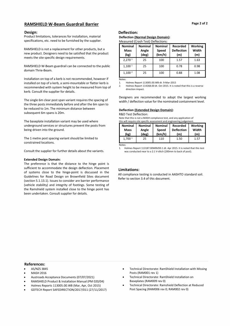
Design:Product limitations, tolerances for installation, material specifications, etc. need to be furnished by the supplier. RAMSHIELD is not a replacement for other products, but a new product. Designers need to be satisfied that the product meets the site specific design requirements. RAMSHIELD W-Beam guardrail can be connected to the public domain Thrie-Beam. Installation on top of a kerb is not recommended, however if installed on top of a kerb, a semi-mountable or flatter kerb is recommended with system height to be measured from top of kerb. Consult the supplier for details. The single 6m clear post span variant requires the spacing of the three posts immediately before and after the 6m span to be reduced to 1m. The minimum distance between subsequent 6m spans is 20m. The baseplate installation variant may be used where underground services or structures prevent the posts from being driven into the ground. The 1 metre post spacing variant should be limited to constrained locations. Consult the supplier for further details about the variants. Extended Design Domain: The preference is that the distance to the hinge point is sufficient to accommodate the design deflection. Placement of systems close to the hinge-point is discussed in the Guidelines for Road Design on Brownfield Sites document (section 5.1.13.1). Issues to consider are barrier performance (vehicle stability) and integrity of footings. Some testing of the Ramshield system installed close to the hinge point has been undertaken. Consult supplier for details.
Limitations:All compliance testing is conducted in AASHTO standard soil. Refer to section 3.4 of this document.
RAMSHIELD W-Beam Guardrail Barrier Page 2 of 2
References: AS/NZS 3845 MASH 2016 Austroads Acceptance Documents (07/07/2021) RAMSHIELD Product & Installation Manual (PM 020/04) Holmes Reports 113005.00.WB (Mar, Apr, Oct 2015) GDTECH Report SAFEDIRECTION/2017/011 (27/11/2017)
Technical Directorate: RamShield Installation with Missing Posts (RAM001 rev 1)
Technical Directorate: RamShield Installation on Baseplates (RAM009 rev 0)
Technical Directorate: Ramshield Deflection at Reduced Post Spacing (RAM006 rev 0; RAM002 rev 0)
Deflection:Deflection (Normal Design Domain): Measured (Crash Test) Deflections:
Nominal Mass (kg)
Nominal Angle (deg)
Nominal Speed (km/h)
Recorded Deflection
(m)
Working Width
(m) 2,270 1 25 100 1.57 1.63
1,100 1 25 100 0.78 0.98
1,100 2 25 100 0.88 1.08
Notes: 1. Holmes Report 113005.00.WB dt. 9-Mar-2015 2. Holmes Report 114268.00 dt. Oct 2015. It is noted that this is a reverse
direction impact. Designers are recommended to adopt the largest working width / deflection value for the nominated containment level. Deflection (Extended Design Domain): R&D Test Deflection: Note that this is not a MASH compliance test, and any application of this will require site specific assessment and engineering judgement.
Nominal Mass (kg)
Nominal Angle (deg)
Nominal Speed (km/h)
Recorded Deflection
(m)
Working Width
(m) 1,700 1 25 110 1.50 1.57
Notes: 1. Holmes Report 113187.00WBVD0.1 dt. Apr 2015. It is noted that this test
was conducted near to a 2:1 V-ditch (200mm to back of post).
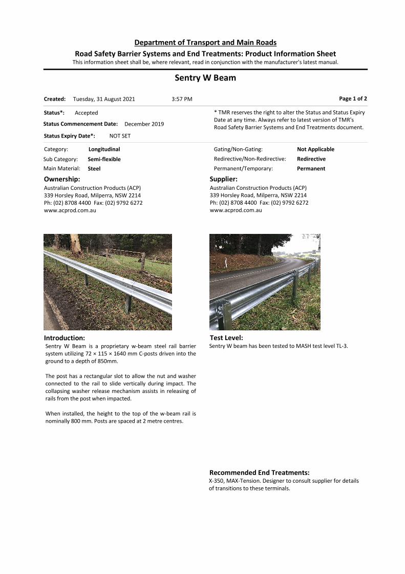
Sentry W Beam
Category: Longitudinal
Permanent/Temporary: Permanent
Introduction:Sentry W Beam is a proprietary w-beam steel rail barrier system utilizing 72 × 115 × 1640 mm C-posts driven into the ground to a depth of 850mm. The post has a rectangular slot to allow the nut and washer connected to the rail to slide vertically during impact. The collapsing washer release mechanism assists in releasing of rails from the post when impacted. When installed, the height to the top of the w-beam rail is nominally 800 mm. Posts are spaced at 2 metre centres.
Ownership:Australian Construction Products (ACP)339 Horsley Road, Milperra, NSW 2214Ph: (02) 8708 4400 Fax: (02) 9792 6272www.acprod.com.au
Supplier:Australian Construction Products (ACP)339 Horsley Road, Milperra, NSW 2214Ph: (02) 8708 4400 Fax: (02) 9792 6272www.acprod.com.au
Page 1 of 2
Test Level:Sentry W beam has been tested to MASH test level TL-3.
Status*: Accepted
Status Commencement Date: December 2019
Status Expiry Date*: NOT SET
* TMR reserves the right to alter the Status and Status Expiry Date at any time. Always refer to latest version of TMR's Road Safety Barrier Systems and End Treatments document.
Gating/Non-Gating: Not Applicable
Redirective/Non-Redirective: Redirective
Main Material: Steel
Sub Category: Semi-flexible
This information sheet shall be, where relevant, read in conjunction with the manufacturer's latest manual.Road Safety Barrier Systems and End Treatments: Product Information Sheet
Department of Transport and Main Roads
3:57 PMTuesday, 31 August 2021Created:
Recommended End Treatments:X-350, MAX-Tension. Designer to consult supplier for details of transitions to these terminals.
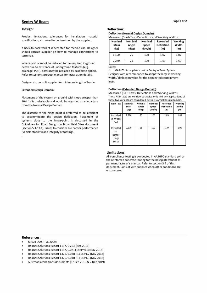
Design: Product limitations, tolerances for installation, material specifications, etc. need to be furnished by the supplier. A back-to-back variant is accepted for median use. Designer should consult supplier on how to manage connections to terminals. Where posts cannot be installed to the required in-ground depth due to existence of underground features (e.g. drainage, PUP), posts may be replaced by baseplate option. Refer to systems product manual for installation details. Designers to consult supplier for minimum length of barrier. Extended Design Domain: Placement of the system on ground with slope steeper than 10H: 1V is undesirable and would be regarded as a departure from the Normal Design Domain. The distance to the hinge point is preferred to be sufficient to accommodate the design deflection. Placement of systems close to the hinge-point is discussed in the Guidelines for Road Design on Brownfield Sites document (section 5.1.13.1). Issues to consider are barrier performance (vehicle stability) and integrity of footings. .
Limitations:All compliance testing is conducted in AASHTO standard soil or the reinforced concrete footing for the baseplate variant as per manufacturer's manual. Refer to section 3.4 of this document. Consult with supplier when other conditions are encountered.
Sentry W Beam Page 2 of 2
References: MASH (AASHTO, 2009) Holmes Solutions Report 113770 v1.3 (Sep 2016) Holmes Solutions Report 113770.021118RP v1.3 (Nov 2018) Holmes Solutions Report 137672.02RP.1118 v1.2 (Nov 2018) Holmes Solutions Report 137672.01RP.1118 v1.3 (Nov 2018) Austroads conditions documents (12 Sep 2019 & 2 Dec 2019)
Deflection:Deflection (Normal Design Domain): Measured (Crash Test) Deflections and Working Widths:
Nominal Mass (kg)
Nominal Angle (deg)
Nominal Speed (km/h)
Recorded Deflection
(m)
Working Width
(m)
1,100¹ 25 100 1.02 1.02
2,270¹ 25 100 1.59 1.59
Notes: 1. MASH TL-3 compliance test on Sentry W Beam System. Designers are recommended to adopt the largest working width / deflection value for the nominated containment level. Deflection (Extended Design Domain): Measured (R&D Tests) Deflections and Working Widths: These R&D tests are considered advice only and any applications of these two variants are considered outside Normal Design Domain.
R&D Test Nominal Mass (kg)
Nominal Angle (deg)
Nominal Speed (km/h)
Recorded Deflection
(m)
Working Width
(m)
Installed in Weak
Soil
2,270 25 100 1.85 1.85
Installed on
Batter Hinge 2H:1V
2,270 25 100 1.79 1.95

Sentry Thrie-Beam
Category: Longitudinal
Permanent/Temporary: Permanent
Introduction:Sentry Thrie-Beam is a proprietary thrie-beam steel rail barrier system utilising 72mm × 115mm × 2000 mm C-posts driven into the ground to a depth of 960mm. When installed, the height to the top of the thrie-beam rail is nominally 1050 mm. Posts are spaced at 2 metre centres. Variant accepted: Baseplate installation. This may be used where
underground services prevent driven posts from being installed. Consult the supplier for further details.
Ownership:Australian Construction Products (ACP)339 Horsley Road, Milperra, NSW 2214Ph: (02) 8708 4400 Fax: (02) 9792 6272www.acprod.com.au
Supplier:Australian Construction Products (ACP)339 Horsley Road, Milperra, NSW 2214Ph: (02) 8708 4400 Fax: (02) 9792 6272www.acprod.com.au
Page 1 of 2
Test Level:MASH TL-4
Status*: Accepted
Status Commencement Date: October 2020
Status Expiry Date*: Not Set
* TMR reserves the right to alter the Status and Status Expiry Date at any time. Always refer to latest version of TMR's Road Safety Barrier Systems and End Treatments document.
Gating/Non-Gating: Not Applicable
Redirective/Non-Redirective: Redirective
Main Material: Steel
Sub Category: Semi-flexible
This information sheet shall be, where relevant, read in conjunction with the manufacturer's latest manual.Road Safety Barrier Systems and End Treatments: Product Information Sheet
Department of Transport and Main Roads
3:57 PMTuesday, 31 August 2021Created:
Recommended End Treatments:MAX-Tension. Designer should consult supplier for details of transitions to this terminal.

Design:Product limitations, tolerances for installation, material specifications, etc. need to be furnished by the supplier. Extended Design Domain: Placement of the system on ground with slope steeper than 10H: 1V is undesirable and would be regarded as a departure from the Normal Design Domain. Refer to Austroads Guide to Road Design Part 6 (2010 Edition) Section 6.2.1 (cross slopes). The distance to the hinge point is preferred to be sufficient to accommodate the design deflection. Placement of systems close to the hinge-point is discussed in the Guidelines for Road Design on Brownfield Sites document (section 5.1.13.1). Issues to consider are barrier performance (vehicle stability) and integrity of footings.
Limitations:All compliance testing is conducted in AASHTO standard soil. Refer to section 3.4 of this document. Consult with supplier when other conditions are encountered.
Sentry Thrie-Beam Page 2 of 2
References: AS/NZS 3845.1: 2015 MASH 2016 Austroads Acceptance Conditions Documents (4 Mar
2021)
Holmes Solutions - ACP MASH TL4 Compliance Testing of the Sentry Thrie-Beam Guardrail System Report 135681.01RP0220 (v1.2) (Feb, 2020)
Deflection:Deflection (Normal Design Domain): Measured (Crash Test) Deflections and Working Widths:
Nominal Mass (kg)
Nominal Angle (deg)
Nominal Speed (km/h)
Recorded Deflection
(m)
Working Width
(m) 1,1001 25 100 1.06 1.21 2,2701 25 100 1.45 1.53
10,0001 15 90 1.53 2.80 Note:
1. MASH TL-4 compliance test on Sentry ThrieBeam. Designers are recommended to adopt the largest working width / deflection value for the nominated containment level.

BRIFEN 4-rope TL-4
Category: Longitudinal
Permanent/Temporary: Permanent
Introduction:Brifen wire rope (4-wire TL-4) is a proprietary flexible barrier system comprising four 19mm wire rope cables supported on a post. Wire rope cable heights are 480mm, 630mm, 780mm and 930mm, the lowest three of which are woven from side to side around alternate posts. Posts are 1430mm long and are supported in a concrete footing, and are “Z” or “S” shaped to suit the direction of traffic. Traffic should pass to the right side of a “Z” post and to the left side of an “S” post. Nominal post spacing is 3.2m.
Ownership:Hill and Smith Pty Ltd1/242 New Cleveland Rd Tingalpa. Q 4173PO Box 9406 Wynnum Plaza, Wynnum West. Q 4178Phone 1300 277 683www.hillandsmith.com.au
Supplier:Hill and Smith Pty Ltd1/242 New Cleveland Rd Tingalpa. Q 4173PO Box 9406 Wynnum Plaza, Wynnum West. Q 4178Phone 1300 277 683www.hillandsmith.com.au
Page 1 of 2
Test Level:NCHRP350 TL4
Status*: Accepted
Status Commencement Date: Not Set
Status Expiry Date*: Not Set
* TMR reserves the right to alter the Status and Status Expiry Date at any time. Always refer to latest version of TMR's Road Safety Barrier Systems and End Treatments document.
Gating/Non-Gating: Not Applicable
Redirective/Non-Redirective: Redirective
Main Material: Wire Rope
Sub Category: Flexible
This information sheet shall be, where relevant, read in conjunction with the manufacturer's latest manual.Road Safety Barrier Systems and End Treatments: Product Information Sheet
Department of Transport and Main Roads
3:57 PMTuesday, 31 August 2021Created:
Recommended End Treatments:BRIFEN End Anchor TL-3
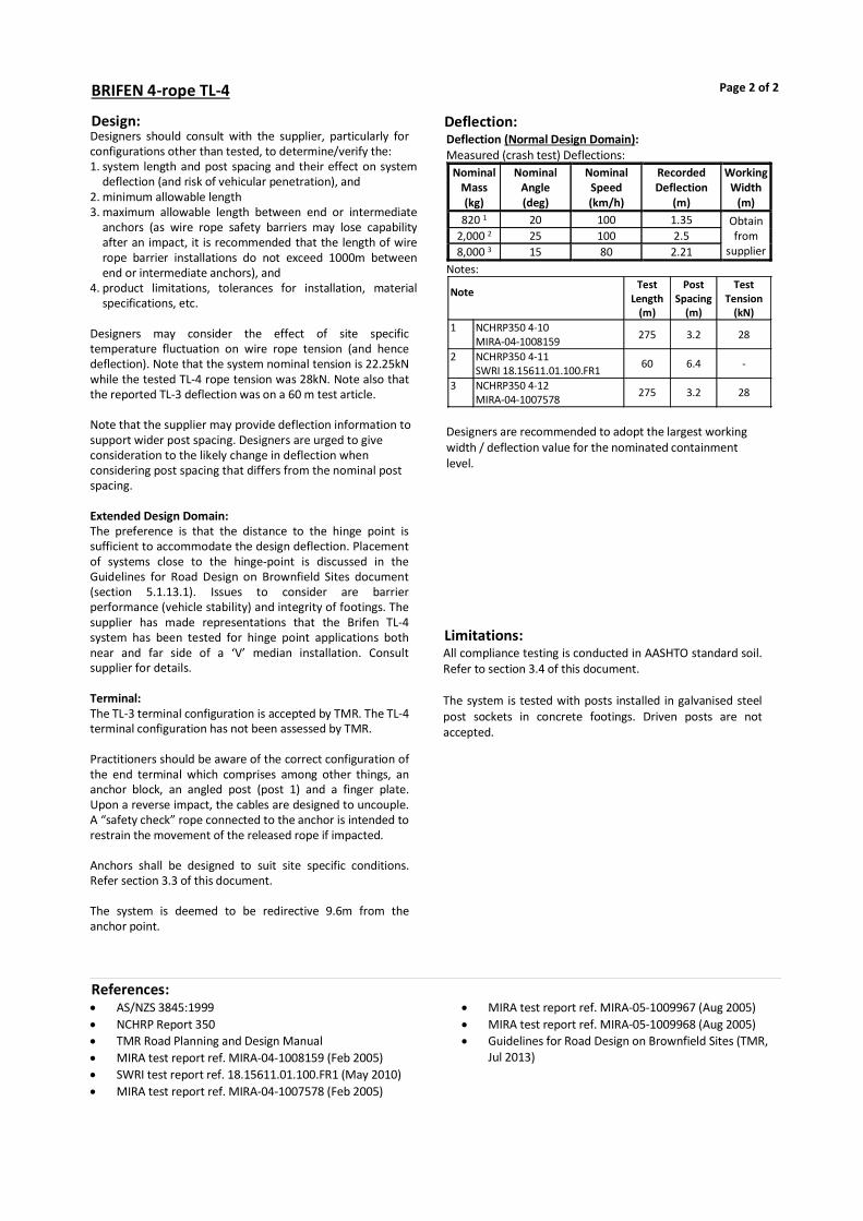
Design:Designers should consult with the supplier, particularly for configurations other than tested, to determine/verify the: 1. system length and post spacing and their effect on system
deflection (and risk of vehicular penetration), and 2. minimum allowable length 3. maximum allowable length between end or intermediate
anchors (as wire rope safety barriers may lose capability after an impact, it is recommended that the length of wire rope barrier installations do not exceed 1000m between end or intermediate anchors), and
4. product limitations, tolerances for installation, material specifications, etc.
Designers may consider the effect of site specific temperature fluctuation on wire rope tension (and hence deflection). Note that the system nominal tension is 22.25kN while the tested TL-4 rope tension was 28kN. Note also that the reported TL-3 deflection was on a 60 m test article. Note that the supplier may provide deflection information to support wider post spacing. Designers are urged to give consideration to the likely change in deflection when considering post spacing that differs from the nominal post spacing. Extended Design Domain: The preference is that the distance to the hinge point is sufficient to accommodate the design deflection. Placement of systems close to the hinge-point is discussed in the Guidelines for Road Design on Brownfield Sites document (section 5.1.13.1). Issues to consider are barrier performance (vehicle stability) and integrity of footings. The supplier has made representations that the Brifen TL-4 system has been tested for hinge point applications both near and far side of a ‘V’ median installation. Consult supplier for details. Terminal: The TL-3 terminal configuration is accepted by TMR. The TL-4 terminal configuration has not been assessed by TMR. Practitioners should be aware of the correct configuration of the end terminal which comprises among other things, an anchor block, an angled post (post 1) and a finger plate. Upon a reverse impact, the cables are designed to uncouple. A “safety check” rope connected to the anchor is intended to restrain the movement of the released rope if impacted. Anchors shall be designed to suit site specific conditions. Refer section 3.3 of this document. The system is deemed to be redirective 9.6m from the anchor point.
Limitations:All compliance testing is conducted in AASHTO standard soil. Refer to section 3.4 of this document. The system is tested with posts installed in galvanised steel post sockets in concrete footings. Driven posts are not accepted.
BRIFEN 4-rope TL-4 Page 2 of 2
References: AS/NZS 3845:1999 NCHRP Report 350 TMR Road Planning and Design Manual MIRA test report ref. MIRA-04-1008159 (Feb 2005) SWRI test report ref. 18.15611.01.100.FR1 (May 2010) MIRA test report ref. MIRA-04-1007578 (Feb 2005)
MIRA test report ref. MIRA-05-1009967 (Aug 2005) MIRA test report ref. MIRA-05-1009968 (Aug 2005) Guidelines for Road Design on Brownfield Sites (TMR,
Jul 2013)
Deflection:Deflection (Normal Design Domain): Measured (crash test) Deflections:
Nominal Mass (kg)
Nominal Angle (deg)
Nominal Speed (km/h)
Recorded Deflection
(m)
Working Width
(m) 820 1 20 100 1.35 Obtain
from supplier
2,000 2 25 100 2.5 8,000 3 15 80 2.21
Notes:
Note Test
Length (m)
Post Spacing
(m)
Test Tension
(kN) 1 NCHRP350 4-10
MIRA-04-1008159 275 3.2 28
2 NCHRP350 4-11 SWRI 18.15611.01.100.FR1
60 6.4 -
3 NCHRP350 4-12 MIRA-04-1007578
275 3.2 28
Designers are recommended to adopt the largest working width / deflection value for the nominated containment level.

Brifen MASH TL3
Category: Longitudinal
Permanent/Temporary: Permanent
Introduction:Brifen MASH TL3 is a proprietary flexible barrier system comprising four 19mm wire rope cables supported on a post. Wire rope cable heights are 355mm, 530mm, 710mm and 890mm. The four cables are supported by 1270mm round posts, 300mm embedment depth into 300mm diameter x 900mm deep concrete footings. Nominal post spacing is 2.1m.
Ownership:Safe Direction 47 Telford CircuitYatala, QLD 4207Ph. 1300 063 220www.safedirection.com.au
Supplier:Safe Direction 47 Telford CircuitYatala, QLD 4207Ph. 1300 063 220www.safedirection.com.au
Page 1 of 2
Test Level:MASH TL3
Status*: Accepted
Status Commencement Date: Not Set
Status Expiry Date*: Not Set
* TMR reserves the right to alter the Status and Status Expiry Date at any time. Always refer to latest version of TMR's Road Safety Barrier Systems and End Treatments document.
Gating/Non-Gating: Not Applicable
Redirective/Non-Redirective: Redirective
Main Material: Wire Rope
Sub Category: Flexible
This information sheet shall be, where relevant, read in conjunction with the manufacturer's latest manual.Road Safety Barrier Systems and End Treatments: Product Information Sheet
Department of Transport and Main Roads
3:57 PMTuesday, 31 August 2021Created:
Recommended End Treatments:Brifen MASH TL3 End Terminal

Design:Product limitations, tolerances for installation, material specifications, etc. need to be furnished by the supplier. Designers may consider the effect of site-specific temperature fluctuation on wire rope tension (and hence deflection). Refer table below for test configuration:
Test Test Length
(m)
Post Spacing
(m)
Test Tension
(kN) MASH 3-10 18.15611.02.103.FR1 187 2.1 14
MASH 3-11 18.15611.02.102.FR1
187 2.1 14
Extended Design Domain: The preference is that the distance to the hinge point is sufficient to accommodate the design deflection. Placement of systems close to the hinge-point is discussed in the Guidelines for Road Design on Brownfield Sites document (section 5.1.13.1). Issues to consider are barrier performance (vehicle stability) and integrity of footings. Terminal: Practitioners should be aware of the correct configuration of the end terminal which comprises among other things, an anchor block, two terminal posts (post 1 and 2) and a deflection post. Anchors shall be designed to suit site specific conditions. Refer section 3.3 of this document. The system is deemed to be redirective 11.25m from the anchor point.
Limitations:All compliance testing is conducted in AASHTO standard soil. Refer to section 3.4 of this document. The system is tested with posts installed in plastic sockets in concrete footings. Driven posts are not accepted.
Brifen MASH TL3 Page 2 of 2
References: AS/NZS 3845.1: 2015 MASH 2016 Austroads acceptance documents dated 20-March-2020
SwRI Report No. 18.15611.02.102.FR1 – Rev 0 (Feb 2013) SwRI Report No. 18.15611.02.103.FR1 – Rev 0 (Feb 2013) Guidelines for Road Design on Brownfield Sites (TMR, Jul
2013)
Deflection:Deflection (Normal Design Domain): Measured (Crash Test) Deflections:
Nominal Mass (kg)
Nominal Angle (deg)
Nominal Speed (km/h)
Recorded Deflection
(m)
Working Width
(m) 1100 1 25 100 1.6 Obtain
from supplier 2270 2 25 100 2.4
Notes: 1. MASH 3-10 test 2. MASH 3-11 test
Designers are recommended to adopt the largest working width / deflection value for the nominated containment level.

Flexfence 4-rope TL-4 (& TL-3) variants
Category: Longitudinal
Permanent/Temporary: Permanent
Introduction:Flexfence is a proprietary flexible barrier system comprising four 19 mm wire rope cables supported on a slotted post. Wire rope cable heights are 480 mm, 560 mm, 640 mm and 720 mm. Posts are 1230 mm long sigma-shaped () posts and are set into 600 mm deep x 300 mm diameter concrete footings. Each post also comprises a stiffening plate at ground level, and a rope hook. Nominal post spacing is 2.5 m. Nominal rope tension in 25 kN. Note that a TL-3 configuration also exists, which differs from the TL-4 system by omission of the ground level stiffening plate and rope hook. The TL-3 system is nominally tensioned to 15 kN. Variants Accepted: Flexfence Driven Sleeve
Ownership:Ingal Civil Products57-65 Airds Road, Minto, NSW 2566Ph: 02 9827 3333Fax: 02 9827 3300www.ingalcivil.com.au
Supplier:Ingal Civil Products7 Nestor Drive, Meadowbrook QLD 4131Ph: 3489 9120 Fax: 3489 9130www.ingalcivil.com.au
Page 1 of 2
Test Level:NCHRP350 TL-4 Designers should note that a TL-3 variant does exist and may be specified for use on state-controlled roads. The data provided in this design sheet pertains to the TL-4 tested system.
Status*: Accepted
Status Commencement Date: Apr 2014
Status Expiry Date*: Not Set
* TMR reserves the right to alter the Status and Status Expiry Date at any time. Always refer to latest version of TMR's Road Safety Barrier Systems and End Treatments document.
Gating/Non-Gating: Not Applicable
Redirective/Non-Redirective: Redirective
Main Material: Wire Rope
Sub Category: Flexible
This information sheet shall be, where relevant, read in conjunction with the manufacturer's latest manual.Road Safety Barrier Systems and End Treatments: Product Information Sheet
Department of Transport and Main Roads
3:57 PMTuesday, 31 August 2021Created:
Recommended End Treatments:Flexfence End Anchor TL-3

Design:Designers should consult with the supplier, particularly for configurations other than tested, to determine/verify the: 1. system length and post spacing and their effect on system
deflection (and risk of vehicular penetration), and 2. minimum allowable length, and 3. maximum allowable length between end or intermediate
anchors (as wire rope safety barriers may lose capability after an impact, it is recommended that the length of wire rope barrier installations do not exceed 1000m between end or intermediate anchors), and
4. product limitations, tolerances for installation, material specifications, etc.
Designers may consider the effect of site specific temperature fluctuation on wire rope tension (and hence deflection). Note that the system nominal tension is 25 kN. The TL-3 deflection was recorded on a 121 m long test article. Note that the supplier may provide deflection information to support wider post spacing. Designers are urged to give consideration to the likely change in deflection when considering post spacing that differs from the nominal post spacing. Extended Design Domain: The preference is that the distance to the hinge point is sufficient to accommodate the design deflection. Placement of systems close to the hinge-point is discussed in the Guidelines for Road Design on Brownfield Sites document (section 5.1.13.1). Issues to consider are barrier performance (vehicle stability) and integrity of footings. To the knowledge of this department, there has not been any testing of the Flexfence systems when installed on or in close proximity to the hinge point. Terminal: Designers should be aware that more than one end treatment configuration exists. The accepted (NCHRP350 tested) end treatment configuration comprises a tapering height from ground level to full height over 11 posts. This terminal shall be used on State Controlled Roads in Queensland. The terminal is sometimes described as a non-release terminal. A “safety check” rope connected to the anchor to restrain the movement of the released rope if impacted is not mandated for this system, but may be supplied if specified. Anchors shall be designed to suit site specific conditions. Refer section 3.3 of this document. The system is deemed to be redirective 12.6m from the anchor point.
Limitations:All compliance testing is conducted in AASHTO standard soil. Refer to section 3.4 of this document. The system is tested with posts installed in post sockets in concrete footings. Driven posts are not accepted.
Flexfence 4-rope Page 2 of 2
References: AS/NZS 3845:1999 NCHRP Report 350 TMR Road Planning and Design Manual Flexfence Product Manual Release 02/14 Holmes Test Report 102350.12-1-2 (Nov 2010) Holmes Test Report 102350.12-1-1 (Nov 2010)
Holmes Test Report 102350.97-8-4-12 (Dec 2011) Guidelines for Road Design on Brownfield Sites (TMR,
Jul 2013)
Deflection:Deflection (Normal Design Domain): Measured (Crash Test) Deflections: TL-4 configuration
Nominal Mass (kg)
Nominal Angle (deg)
Nominal Speed (km/h)
Recorded Deflection
(m)
Working Width
(m)
820 1 20 100 1.28 Obtain from
supplier 2,000 2,4 25 100 1.41
8,000 3 15 80 1.21 2 Notes: Notes Test Length
(m) Post Spacing
(m) Test Tension
(kN) 1 = NCHRP 350 4-10 121 2.5 25 2 = NCHRP 350 4-11 121 2.5 25 3 = NCHRP 350 4-12 85 2.5 25 4 Test deflection is recorded as 1.41m. However
1.90m should be adopted to allow for working width/vehicle overhang.
TL-3 configuration Contact supplier for test deflections derived from crash testing of test level TL-3 configuration. Refer to the following: Flexfence Product Manual Release 004 VTI Test Report ref. 56379 VTI Test Report ref. 56419 VTI Test Report ref. 56592 Designers are recommended to adopt the largest working width/ deflection value for the nominated containment level.

MashFlex
Category: Longitudinal
Permanent/Temporary: Permanent
Introduction:MashFlex is a proprietary flexible barrier system comprising four 19mm wire rope cables supported on a post. Wire rope cable heights are 570mm, 670mm, 780mm and 800mm. The four cables are supported by 1230mm sigma posts, 350mm embedment depth into 300mm diameter x 600mm deep concrete footings. Nominal post spacing is 2.5m. Variants accepted: 3m post spacing 780mm long driven post sleeve Baseplate installation. This may be used where
underground services prevent the posts from being installed in a standard concrete footing, supported by a risk assessment report. Consult the supplier for further details.
Ownership:Blue SystemsFiskebäcks Hamn 16, SE-426 58 Västra Frölunda, SwedenPh: +46 (0) 31-29 72 16www.bluesystems.se
Supplier:Ingal Civil Products57-65 Airds Road, Minto, NSW 2566Ph: 02 9827 3333Fax: 02 9827 3300www.ingalcivil.com.au
Page 1 of 2
Test Level:MASH TL-3
Status*: Accepted
Status Commencement Date: Not Set
Status Expiry Date*: Not Set
* TMR reserves the right to alter the Status and Status Expiry Date at any time. Always refer to latest version of TMR's Road Safety Barrier Systems and End Treatments document.
Gating/Non-Gating: Not Applicable
Redirective/Non-Redirective: Redirective
Main Material: Wire Rope
Sub Category: Flexible
This information sheet shall be, where relevant, read in conjunction with the manufacturer's latest manual.Road Safety Barrier Systems and End Treatments: Product Information Sheet
Department of Transport and Main Roads
3:57 PMTuesday, 31 August 2021Created:
Recommended End Treatments:MashFlex Terminal

Design:Product limitations, tolerances for installation, material specifications, etc. need to be furnished by the supplier. Designers may consider the effect of site-specific temperature fluctuation on wire rope tension (and hence deflection). The system is deemed to be redirective 11.73m from the anchor point. Refer table below for test configuration:
Test Test Length
(m)
Post Spacing
(m)
Test Tension
(kN) MASH 3-10 188 2.5 25
MASH 3-11 188 2.5 25 MASH 3-11 183 3 25
Extended Design Domain: The preference is that the distance to the hinge point is sufficient to accommodate the design deflection. Placement of systems close to the hinge point is discussed in the Guidelines for Road Design on Brownfield Sites document (section 5.1.13.1). Issues to consider are barrier performance (vehicle stability) and integrity of footings. Terminal: Practitioners should be aware of the correct configuration of the MashFlex terminal. Designers should consult with the supplier for the details of terminal. Anchors shall be designed to suit site specific conditions. Refer section 3.3 of this document. As it is a gating terminal, a hazard free area immediately behind the terminal should be considered.
Limitations:All compliance testing is conducted in AASHTO standard soil. Refer to section 3.4 of this document. The system is tested with posts installed in plastic sockets in concrete footings. A 780mm driven post sleeve may be an option in lieu of the 600mm deep concrete footings.
MashFlex Page 2 of 2
References: AS/NZS 3845.1: 2015 MASH 2016 Austroads acceptance documents (22 Mar 2021) Holmes Solutions - MashFlex 3-10, 3-11, and 3-35 Test
Reports (2019)
VTI MASH 3-30 Test Reports 3-30, 3-31, 3- 32, 3-33, 3-34 and 3-37b Test Reports (2019)
Guidelines for Road Design on Brownfield Sites (TMR, Jul 2013)
Deflection:Deflection (Normal Design Domain): Measured (Crash Test) Deflections:
Nominal Mass (kg)
Nominal Angle (deg)
Nominal Speed (km/h)
Recorded Deflection
(m)
Working Width
(m) 1100 1 25 100 1.71 1.71 2270 2 25 100 2.19 2.19 2270 3 25 100 2.68 2.73
Notes: 1. MASH 3-10 test (2.5m post spacing) 2. MASH 3-11 test (2.5m post spacing) 3. MASH 3-11 test (3m post spacing)
Designers are recommended to adopt the largest working
width / deflection value for the nominated containment level.

SENTRYLINE II 4-rope TL-4
Category: Longitudinal
Permanent/Temporary: Permanent
Introduction:Sentryline II (4-wire TL-4) is a proprietary flexible barrier system comprising four 19mm wire rope cables supported in notches in flat-sided hollow, oval section posts with two ropes placed in a central slot. Cable heights are 530mm, 650mm, 770mm and 790mm. Nominal cable tension is 25kN. Note that despite what is depicted, posts should be white unless specified otherwise. Practitioners should note that this system has two terminal options.
Ownership:Australian Construction Products (ACP)339 Horsley Road, Milperra, NSW 2214Ph. 1800 724 172www.acprod.com.au
Supplier:Australian Construction Products (ACP)339 Horsley Road, Milperra, NSW 2214Ph. 1800 724 172www.acprod.com.au
Page 1 of 2
Test Level:NCHRP Report 350 TL-4
Status*: Accepted
Status Commencement Date: Not Set
Status Expiry Date*: Not Set
* TMR reserves the right to alter the Status and Status Expiry Date at any time. Always refer to latest version of TMR's Road Safety Barrier Systems and End Treatments document.
Gating/Non-Gating: Not Applicable
Redirective/Non-Redirective: Redirective
Main Material: Wire Rope
Sub Category: Flexible
This information sheet shall be, where relevant, read in conjunction with the manufacturer's latest manual.Road Safety Barrier Systems and End Treatments: Product Information Sheet
Department of Transport and Main Roads
3:57 PMTuesday, 31 August 2021Created:
Recommended End Treatments:Two options: SENTRYLINE II End Anchor TL-3 SENTRYLINE Terminal End III TL-3

Design:Designers should consult with the supplier, particularly for configurations other than tested, to determine/verify the: 1. system length and post spacing and their effect on system
deflection (and risk of vehicular penetration), and 2. minimum allowable length, and 3. maximum allowable length between end or intermediate
anchors (as wire rope safety barriers may lose capability after an impact, it is recommended that the length of wire rope barrier installations do not exceed 1000m between end or intermediate anchors), and
4. product limitations, tolerances for installation, material specifications, etc.
Designers may consider the effect of site specific temperature fluctuation on wire rope tension (and hence deflection). Note that the system nominal tension is 25 kN. The TL-3 deflection was recorded on a 130 m long test article. Note that the supplier may provide deflection information to support wider post spacing. Designers are urged to give consideration to the likely change in deflection when considering post spacing that differs from the nominal post spacing. Extended Design Domain: The preference is that the distance to the hinge point is sufficient to accommodate the design deflection. Placement of systems close to the hinge-point is discussed in the Guidelines for Road Design on Brownfield Sites document (section 5.1.13.1). Issues to consider are barrier performance (vehicle stability) and integrity of footings. Designer should seek advice from supplier regarding any testing of the Sentryline system when installed on or in close proximity to the hinge point. Terminal: Designers should be aware that more than one end treatment configuration exists. Both are accepted for use on state-controlled roads in Queensland, so the designer must specify which terminal is required. The Sentryline II terminal is a “releasing” terminal, is designed to release on impact and DOES NOT employ the use of a safety check rope. The system is deemed to be redirective 8.0 m from the anchor point. The Sentryline III terminal is described as a non-releasing terminal. A “safety check” rope connected to the anchor to restrain the movement of the released rope if impacted is not mandated for this system, but may be supplied if specified. The system is deemed to be redirective 8.0 m from the anchor point. Anchors shall be designed to suit site specific conditions. Refer section 3.3 of this document.
Limitations:All compliance testing is conducted in AASHTO standard soil. Refer to section 3.4 of this document. The system is tested with posts installed in post sockets in concrete footings. Driven posts are not accepted. Practitioners should be aware that there are two methods of connecting sections of wire rope. The accepted method is a fully swaged coupling. The spring-loaded coupling is not accepted for new installations.
SENTRYLINE II 4-rope TL-4 Page 2 of 2
References: AS/NZS 3845 NCHRP Report 350 TMR Road Planning and Design Manual Sentryline II Product and Installation Manual (ACP, Dec
2016) Sentryline II Terminal Manual (ACP, Jun 2016)
Sentryline Terminal End III Manual (ACP, Feb 2017) Holmes Report ref. 102350.02-6 (Feb 2010) Holmes Report ref. 102350.02-6-311 (Aug 2009) Holmes Report ref. 102350.02-6-412 (Aug 2009) Guidelines for Road Design on Brownfield Sites (TMR, Jul
2013)
Deflection:Deflection (Normal Design Domain): Measured (Crash Test) Deflections:
Nominal Mass (kg)
Nominal Angle (deg)
Nominal Speed (km/h)
Recorded Deflection
(m)
Working Width
(m)
820 1 20 100 1.28 Obtain from
supplier 2,000 2 25 100 1.54 1.54
8,000 3,4 15 80 1.65 2.15 Notes: Notes Test
Length (m)
Post Spacing
(m)
Test Tension
(kN) 1. NCHRP350 4-10
102350.02-6 (Feb 2010) 120 3.0 -
2. NCHRP350 4-11 102350.02-6-311 (Aug 2009) 130 3.0 25
3. NCHRP350 4-12 102350.02-6-412 (Aug 2009) 130 3.0 25
4. Test vehicle impacted twice. First impact deflected 1.1m, 2nd impact deflected 1.65m.
Designers are recommended to adopt the largest working
width / deflection value for the nominated containment level.

SENTRYLINE-M
Category: Longitudinal
Permanent/Temporary: Permanent
Introduction:Sentryline-M is a proprietary flexible barrier system comprising four 19mm wire rope cables supported on a post. Wire rope cable heights are 590mm, 700mm, 800mm and 900mm. The four cables are supported by 1370mm posts, 400mm embedment depth into 300mm diameter x 750mm deep concrete footings. Nominal post spacing is 3m. Variants accepted: 2m post spacing (TL-3) 1100mm long driven post sleeve (TL-3) Baseplate installation (TL-4). This may be used where
underground services prevent the posts from being installed in a standard concrete footing, supported by a risk assessment report. Consult the supplier for further details.
Ownership:CSP PacificPO Box 12 949Penrose, Auckland 1642, New Zealandwww.csppacific.co.nz
Supplier:Australian Construction Products (ACP)339 Horsley Road, Milperra, NSW 2214Ph. 1800 724 172www.acprod.com.au
Page 1 of 2
Test Level:MASH TL-3 and TL-4.
Status*: Accepted
Status Commencement Date: July 2020
Status Expiry Date*: Not Set
* TMR reserves the right to alter the Status and Status Expiry Date at any time. Always refer to latest version of TMR's Road Safety Barrier Systems and End Treatments document.
Gating/Non-Gating: Not Applicable
Redirective/Non-Redirective: Redirective
Main Material: Wire Rope
Sub Category: Flexible
This information sheet shall be, where relevant, read in conjunction with the manufacturer's latest manual.Road Safety Barrier Systems and End Treatments: Product Information Sheet
Department of Transport and Main Roads
3:57 PMTuesday, 31 August 2021Created:
Recommended End Treatments:Sentryline-M Wire Rope Terminal End (MASH TL-3)

Design: Product limitations, tolerances for installation, material specifications, etc. need to be furnished by the supplier. Designers may consider the effect of site-specific temperature fluctuation on wire rope tension (and hence deflection). Refer table below for test configuration:
Test Test Length
(m)
Post Spacing
(m)
Test Tension
(kN) MASH 4-10 185 3 25 MASH 4-11 185 3 25 MASH 4-12 185 3 25 MASH 3-11 165 2 25
Note: 1. Holmes Solutions Length of Need MAST TL-4 Test Report
137460.01RP1219 (v1.3) 2. Holmes Solutions 2.0m Post Spacing MASH TL3-11 Report
137460.03RP0120 (v1.2) Extended Design Domain: The preference is that the distance to the hinge point is sufficient to accommodate the design deflection. Placement of systems close to the hinge-point is discussed in the Guidelines for Road Design on Brownfield Sites document (section 5.1.13.1). Issues to consider are barrier performance (vehicle stability) and integrity of footings. Terminal: Practitioners should be aware of the correct configuration of the end terminal which comprises one trigger post, one deflection post, five transition posts, three line posts, etc. Anchors shall be designed to suit site specific conditions. Refer section 3.3 of this document. The system is deemed to be redirective 300mm upstream of transition post five (TP5), approximately 15.5m from the most upstream point of the terminal end system.
Limitations:All compliance testing is conducted in AASHTO standard soil. Refer to section 3.4 of this document. The system is tested with posts installed in post sockets in concrete footings. A 1100mm long steel rectangular driven post sleeve may be an option in lieu of the 750mm deep concrete footings.
SENTRYLINE-M Page 2 of 2
References: AS/NZS 3845 MASH 2016 Austroads acceptance documents (19 June 2020) Holmes Length of Need MASH TL-4 Test Report
137460.01RP1219 (v1.3) (December 2019) Holmes Terminal End MASH TL-3 Test Report
137460.02RP1219(v1.2) (December 2019)
Holmes 2.0m Post Spacing MASH TL3-11 Report 137460.03RP0120 (v1.2) (February 2020)
Holmes Driven Post Sockets TL3-11 Report 137460.04RP0220 (v1.2) (March 2020)
Guidelines for Road Design on Brownfield Sites (TMR, July 2013)
Deflection:Deflection (Normal Design Domain): Measured (Crash Test) Deflections:
Nominal Mass (kg)
Nominal Angle (deg)
Nominal Speed (km/h)
Recorded Deflection
(m)
Working Width
(m) 1,100 1 25 100 1.80 2 2,270 2 25 100 3.02 3.02
10,000 3 15 90 2.15 3.05 2,270 4 25 100 2.14 2.14
Notes: 1. MASH 4-10 test (3m post spacing) 2. MASH 4-11 test (3m post spacing) 3. MASH 4-12 test (3m post spacing) 4. MASH 3-11 test (2m post spacing)
Designers are recommended to adopt the largest working width/ deflection value for the nominated containment level. Deflection (Extended Design Domain): Measured (R&D Test) Deflection: Note that this is not a MASH compliance test, and any application of this will require site specific assessment and engineering judgement.
Nominal Mass (kg)
Nominal Angle (deg)
Nominal Speed (km/h)
Recorded Deflection
(m)
Working Width
(m) 2,270 1,2 25 100 2.66 2.75
Notes: 1. MASH Modified 3-11 test (1100mm long driven post
sleeve; 3m post spacing) 2. The R&D test vehicle was a non-standard vehicle.
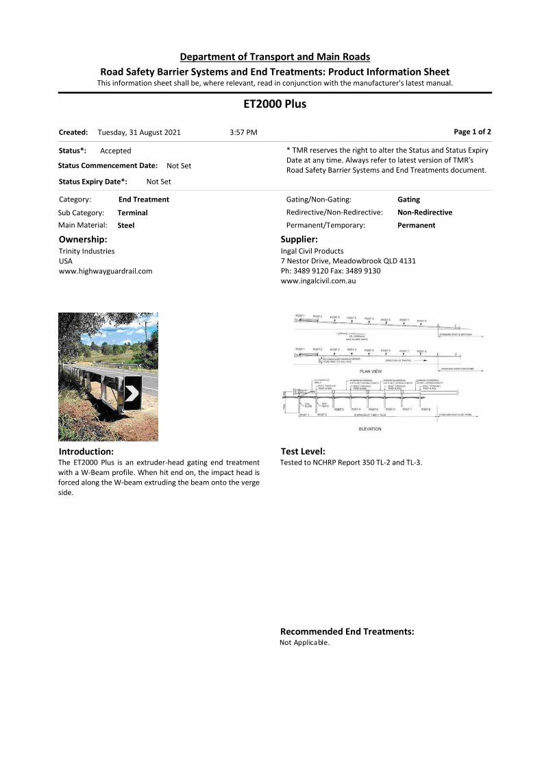
ET2000 Plus
Category: End Treatment
Permanent/Temporary: Permanent
Introduction:The ET2000 Plus is an extruder-head gating end treatment with a W-Beam profile. When hit end on, the impact head is forced along the W-beam extruding the beam onto the verge side.
Ownership:Trinity Industries USAwww.highwayguardrail.com
Supplier:Ingal Civil Products7 Nestor Drive, Meadowbrook QLD 4131Ph: 3489 9120 Fax: 3489 9130www.ingalcivil.com.au
Page 1 of 2
Test Level:Tested to NCHRP Report 350 TL-2 and TL-3.
Status*: Accepted
Status Commencement Date: Not Set
Status Expiry Date*: Not Set
* TMR reserves the right to alter the Status and Status Expiry Date at any time. Always refer to latest version of TMR's Road Safety Barrier Systems and End Treatments document.
Gating/Non-Gating: Gating
Redirective/Non-Redirective: Non-Redirective
Main Material: Steel
Sub Category: Terminal
This information sheet shall be, where relevant, read in conjunction with the manufacturer's latest manual.Road Safety Barrier Systems and End Treatments: Product Information Sheet
Department of Transport and Main Roads
3:57 PMTuesday, 31 August 2021Created:
Recommended End Treatments:Not Applicable.

Design: Design to be in accordance with the ET2000 Plus Design
Manual provided by Ingal and in accordance with provisions of TMR Road Planning and Design Manual.
Preferred plan layout is to install the terminal at a flare (25:1).
In locations of constrained width or on high embankments where the cost to provide additional width is not warranted then the terminal may be installed parallel to the edge of the roadway.
Consideration should be given to the risk especially to vulnerable road users as a result of the impact head intruding beyond the face of the barrier. Also see “motorcyclist protection” below.
As the end terminal is gating, a run-out area in accordance with the requirements of AS/NZS 3845 Figure F11 should be provided.
Length of need (L.O.N.) commences at 3rd post measured from the head of the system.
Installation & Repair Installation and repair to be in accordance with the
ET2000 Plus Design Manual provided by Ingal.
Test Level: Tested in accordance with NCHRP Report 350 to Test
Level 3 (TL-3) and Test Level 2 (TL-2).
Configuration: First post is a Hinged Breakaway (HBA) Post with the
remaining posts being Steel Yielding Terminal (SYT) Posts
Polymer offset blockouts are used.
Test Level (TL) Length (m) 2 7.62 3 15.24
Motorcyclist Protection The device may be deployed with plastic cover components for the head of the device when there is a relatively higher risk of motorcyclist impact, for example, roads that carry large numbers of motorcyclists or where there is evidence to suggest a higher potential for motorcycle related incidents. Accepted variants: Motorcyclist Protection Shield Head Cover
Limitations: Maximum flare is 25:1. Cannot be used on crossfalls steeper than 8%. Installing in proximity to kerbs is not recommended.
Consult Austroads Guide to Road Design Part 6/6.3.22.
ET2000 Plus Page 2 of 2
References: AS/NZS 3845 NCHRP Report 350 TMR Road Planning and Design Manual Ingal Civil Products ET2000 Plus Product Manual (08/14) FHWA memo ref. HSST dated 17-Jun-2014 Austroads acceptance document dated 8-Jan-2016
Guide to Road Design Part 6 (Austroads, 2009)
Deflection:Information has not been entered.

ET-SS
Category: End Treatment
Permanent/Temporary: Permanent
Introduction:The ET-SS is an extruder-head gating end treatment with a W-Beam profile. When hit end on, the impact head is forced along the W-beam extruding the beam through the chute towards front of the system. Variant accepted: Alternative anchor post foundation (shorter anchor
post). This may be applied to the constrained locations where a standard driven post cannot be installed, and should be regarded as a departure from the Normal Design Domain. Consult the supplier for the details of foundation design.
Ownership:Trinity Highway Products LLCUSA
Supplier:Ingal Civil Products7 Nestor Drive, Meadowbrook QLD 4131Ph: 3489 9120 www.ingalcivil.com.au
Page 1 of 2
Test Level:MASH TL-2 & TL-3.
Status*: Accepted
Status Commencement Date: Not Set
Status Expiry Date*: Not Set
* TMR reserves the right to alter the Status and Status Expiry Date at any time. Always refer to latest version of TMR's Road Safety Barrier Systems and End Treatments document.
Gating/Non-Gating: Gating
Redirective/Non-Redirective: Non-Redirective
Main Material: Steel
Sub Category: Terminal
This information sheet shall be, where relevant, read in conjunction with the manufacturer's latest manual.Road Safety Barrier Systems and End Treatments: Product Information Sheet
Department of Transport and Main Roads
3:57 PMTuesday, 31 August 2021Created:
Recommended End Treatments:Not Applicable.
Design:Design: Design to be in accordance with the ET-SS Design
Manual provided by Ingal. Preferred plan layout is to install the terminal at a flare
(25:1). In locations of constrained width or on high
embankments where the cost to provide additional width is not warranted then the terminal may be installed parallel to the edge of the roadway.
As the end terminal is gating, a hazard free zone behind the terminal should be provided.
Length of need (L.O.N.) commences at Post 3, 3.63 metres "downstream" of the Post 1.
Installation & Repair Installation and repair to be in accordance with advice
from Ingal Civil Products.
Configuration: The Post 1 and 2 are Steel Yielding Terminal (SYT) Posts Polymer offset blockouts are used. System Length:
Length (m) Test Level (TL) 7.9 2 15.48 3
Motorcyclist Protection The device may be deployed with plastic cover components for the front of the terminal when there is a relatively higher risk of motorcyclist impact, for example, roads that carry large numbers of motorcyclists or where there is evidence to suggest a higher potential for motorcycle related incidents. Accepted variant: ET-SS Terminal Cover
Limitations: Maximum flare is 25:1. Cannot be used on crossfalls steeper than 10%. Installing in proximity to kerbs is not recommended.
ET-SS Page 2 of 2
References: Australian Standard AS/NZS 3845 TMR RPDM 2nd Edition Volume 3 Part 6 ET-SS Product Manual (Release 04/21) Austroads acceptance documents (4 Mar 2021)
Deflection:Not applicable.

FLEAT-SP
Category: End Treatment
Permanent/Temporary: Permanent
Introduction:The FLEAT is an extruder gating end treatment. When hit end on the impact head is forced along the W-beam extruding the beam onto the same side as the traffic.
Variant Acceptance FLEAT-350
Out of Production May remain in use on State-controlled roads to be replaced at the end of service life.
FLEAT-SP Current May be used on State-controlled road projects.
Ownership:Road SystemsTexas. USA www.roadsystems.com
Supplier:Safe Direction47 Telford CircuitYatala, QLD 4207Ph. 1300 063 220www.safedirection.com.au
Page 1 of 2
Test Level:Both variants satisfy the requirements of NCHRP Report 350 TL-2 and TL-3.
Status*: Accepted
Status Commencement Date: Not Set
Status Expiry Date*: Not Set
* TMR reserves the right to alter the Status and Status Expiry Date at any time. Always refer to latest version of TMR's Road Safety Barrier Systems and End Treatments document.
Gating/Non-Gating: Gating
Redirective/Non-Redirective: Non-Redirective
Main Material: Steel
Sub Category: Terminal
This information sheet shall be, where relevant, read in conjunction with the manufacturer's latest manual.Road Safety Barrier Systems and End Treatments: Product Information Sheet
Department of Transport and Main Roads
3:57 PMTuesday, 31 August 2021Created:
Recommended End Treatments:Not Applicable.

Design: Design to be in accordance with the FLEAT-SP Design
Manual provided by Safe Direction and in accordance with provisions of TMR Road Planning and Design Manual.
Must be installed on a flare (straight taper). The flare of the terminal can be varied to suit site
constraints. Consideration should be given to the risk especially to
vulnerable road users as a result of the impact head intruding beyond the face of the barrier.
As the end terminal is gating, a run-out area in accordance with the requirements of AS/NZS 3845 Figure F11 should be provided.
Length of need (L.O.N.) commences at 3rd post measured from the head of the system.
Designers should note that when impacted the FLEAT-SP extrudes rail onto the “traffic side” of the longitudinal barrier.
Installation & Repair Installation and repair to be in accordance with the
FLEAT-SP Installation & Repair Manual provided by Safe Direction.
Test Level: Tested in accordance with NCHRP 350 to Test Level 3
(TL-3) and Test Level 2 (TL-2). Configuration: The terminal features an anchor post at post location 1
and hinged breakaway post at post location 2. The remaining posts are steel line posts (I-beam) as specified in FHWA Letter CC-88B.
Polymer offset blockouts are used instead of timber blockouts.
Test Level (TL) Length (m) Allowable Flare (m)
2 7.62 510 – 810mm 3 11.43 760 – 1220mm
Limitations: Must be installed on a flare (straight taper). Shall not be
used in situation where there is less than 2.9m between the impact head and the nearest edge of traffic lane.
Cannot be used on crossfalls steeper than 8%. Installing in proximity to kerbs is not recommended.
Consult Austroads Guide to Road Design Part 6/6.3.22.
FLEAT-SP Page 2 of 2
References: AS/NZS 3845:1999 NCHRP Report 350 TMR Road Planning and Design Manual FHWA letters ref. CC-46, CC-61 and CC-88 (various
suffices) Safe Direction Product Manual ref. PM 018/02
Safe Direction Installation and Repair Manual IM 002/02
Guide to Road Design Part 6 (Austroads, 2009)
Deflection:Not applicable.

MSKT
Category: End Treatment
Permanent/Temporary: Permanent
Introduction:The MASH Sequential Kinking Terminal (MSKT) is an extruder gating end treatment. When hit end on the impact head is forced along the W-beam extruding the beam onto the rear of the barrier.
Ownership:Road Systems Inc3616 Howard County AirportBig Spring, Texas. USA www.roadsystems.com
Supplier:Safe Direction47 Telford CircuitYatala, QLD 4207Ph. 1300 063 220www.safedirection.com.au
Page 1 of 2
Test Level:MASH TL-2 & TL-3
Status*: Accepted
Status Commencement Date: Not Set
Status Expiry Date*: Not Set
* TMR reserves the right to alter the Status and Status Expiry Date at any time. Always refer to latest version of TMR's Road Safety Barrier Systems and End Treatments document.
Gating/Non-Gating: Gating
Redirective/Non-Redirective: Non-Redirective
Main Material: Steel
Sub Category: Terminal
This information sheet shall be, where relevant, read in conjunction with the manufacturer's latest manual.Road Safety Barrier Systems and End Treatments: Product Information Sheet
Department of Transport and Main Roads
3:57 PMTuesday, 31 August 2021Created:
Recommended End Treatments:Not applicable.

Design: Design to be in accordance with the MSKT Design
Manual provided by Safe Direction. Preferred plan layout is to install the terminal at a flare
of 25:1 (straight taper). In locations of constrained width or on high
embankments where the cost to provide additional width is not warranted then the terminal may be installed parallel to the edge of the roadway.
Consideration should be given to the risk especially to vulnerable road users as a result of the impact head intruding beyond the face of the barrier.
As the end terminal is gating, a hazard free zone behind the terminal should be provided.
Length of need (L.O.N.) commences at 3rd post measured from the head of the system.
Height Transitions The rail height in the MSKT is 790mm. Transition to
longitudinal w-beam systems of different heights shall be at least 8m long.
Test Level (TL) Length (m) Allowable Flare (m) 2 9.52 0 – 300mm 3 14.29 0 – 600mm
Limitations: Maximum flare is 25:1. Cannot be used on crossfalls steeper than 10%. Installing in proximity to kerbs is not recommended.
MSKT Page 2 of 2
References: Australian Standard AS/NZS 3845 QTMR RPDM 2nd Edition Volume 3 Part 6 SafeDirection letter dated 18-Dec-2018 MSKT Product Manual – Safe Direction; Ref: PM022/01 Austroads acceptance document (7-Jun-2021)
Deflection:Not applicable.

SKT-SP
Category: End Treatment
Permanent/Temporary: Permanent
Introduction:The Sequential Kinking Terminal (SKT) is an extruder an extruder gating end treatment. When hit end on the impact head is forced along the W-beam extruding the beam onto the rear of the barrier.
Variant Acceptance SKT-350
Out of Production May remain in use on State-controlled roads to be replaced at the end of service life.
SKT-SP Current May be used on State-controlled road projects.
Ownership:Road SystemsTexas. USA www.roadsystems.com
Supplier:Safe Direction47 Telford CircuitYatala, QLD 4207Ph. 1300 063 220www.safedirection.com.au
Page 1 of 2
Test Level:Both variants satisfy the requirements of NCHRP Report 350 TL-2 and TL-3.
Status*: Accepted
Status Commencement Date: Not Set
Status Expiry Date*: Not Set
* TMR reserves the right to alter the Status and Status Expiry Date at any time. Always refer to latest version of TMR's Road Safety Barrier Systems and End Treatments document.
Gating/Non-Gating: Gating
Redirective/Non-Redirective: Non-Redirective
Main Material: Steel
Sub Category: Terminal
This information sheet shall be, where relevant, read in conjunction with the manufacturer's latest manual.Road Safety Barrier Systems and End Treatments: Product Information Sheet
Department of Transport and Main Roads
3:57 PMTuesday, 31 August 2021Created:
Recommended End Treatments:Not Applicable.

Design: Design to be in accordance with the SKT-SP Design
Manual provided by Safe Direction and in accordance with provisions of TMR Road Planning and Design Manual.
Preferred plan layout is to install the terminal at a flare of 25:1 (straight taper).
In locations of constrained width or on high embankments where the cost to provide additional width is not warranted then the terminal may be installed parallel to the edge of the roadway.
Consideration should be given to the risk especially to vulnerable road users as a result of the impact head intruding beyond the face of the barrier.
As the end terminal is gating, a run-out area in accordance with the requirements of AS/NZS 3845 Figure F11 should be provided.
Length of need (L.O.N.) commences at 3rd post measured from the head of the system.
Installation & Repair Installation and repair to be in accordance with the SKT-
SP Installation & Repair Manual provided by Safe Direction.
Test Level: Tested in accordance with NCHRP Report 350 to Test
Level 3 (TL-3) and Test Level 2 (TL-2). Configuration: The terminal features an anchor post at post location 1
and hinged breakaway post at post location 2. The remaining posts are steel line posts (I-beam) as specified in FHWA Letter CC-88B.
Polymer offset blockouts are used instead of timber blockouts.
Test Level (TL) Length (m) Allowable Flare (m)
2 7.62 0 – 300mm 3 15.24 0 – 600mm
Limitations: Maximum flare is 25:1. Cannot be used on crosssfalls steeper than 8%. Installing in proximity to kerbs is not recommended.
Consult Austroads Guide to Road Design Part 6/6.3.22.
SKT-SP Page 2 of 2
References: AS/NZS 3845:1999 NCHRP Report 350 TMR Road Planning and Design Manual FHWA letters ref. CC-46, CC-61 and CC-88 (various
suffices) Safe Direction Product Manual ref. PM 017/02
Safe Direction Installation and Repair Manual IM 002/02
Guide to Road Design Part 6 (Austroads, 2009)
Deflection:Not applicable.

TREND-350
Category: End Treatment
Permanent/Temporary: Permanent
Introduction:The TREND-350 is a tangential gating end-treatment for w-beam guardrail. It has met the requirements of NCHRP Report 350 test level TL-3. The length of effective barrier commences at Post 3, 4.25 metres “downstream” of the impact head. The device is 11.9m long overall.
Ownership:Trinity Industries USAwww.highwayguardrail.com
Supplier:Ingal Civil Products7 Nestor Drive, Meadowbrook QLD 4131Ph: 3489 9120 Fax: 3489 9130www.ingalcivil.com.au
Page 1 of 2
Test Level:Tested in accordance with NCHRP 350 to TL-3.
Status*: Accepted
Status Commencement Date: Jul 2015
Status Expiry Date*: Not Set
* TMR reserves the right to alter the Status and Status Expiry Date at any time. Always refer to latest version of TMR's Road Safety Barrier Systems and End Treatments document.
Gating/Non-Gating: Gating
Redirective/Non-Redirective: Non-Redirective
Main Material: Steel
Sub Category: Terminal
This information sheet shall be, where relevant, read in conjunction with the manufacturer's latest manual.Road Safety Barrier Systems and End Treatments: Product Information Sheet
Department of Transport and Main Roads
3:57 PMTuesday, 31 August 2021Created:
Recommended End Treatments:Not Applicable.

Design: Design to be in accordance with the TREND-350 Design
Manual (Nov 2014) provided by Ingal Civil Products and in accordance with provisions of TMR Road Planning and Design Manual.
Consideration should be given to the risk especially to vulnerable road users as a result of the impact head intruding beyond the face of the barrier.
As the end terminal is gating, a run-out area in accordance with the requirements of AS/NZS 3845 Figure F11 should be provided.
Length of need (L.O.N.) commences at 3rd post measured from the head of the system.
Installation & Repair Installation and repair to be in accordance with advice
from Ingal Civil Products.
Test Level: Tested in accordance with NCHRP Report 350 to Test
Level 3 (TL-3). Configuration: First post is a Hinged Breakaway (HBA) Post with post
#2 being a Steel Yielding Terminal (SYT) Post. See p19 of Manual.
Posts 3-7 are W6x8.5 Line Posts. System length 11.9m Installation has been assessed and accepted on the
basis that it is installed tangential/parallel (i.e., without a flare).
Limitations: Cannot be used on crossfalls steeper than 10%. 2.7 metres minimum distance between post and the
edge of an excavation. Installing in proximity to kerbs is not recommended.
Consult Austroads Guide to Road Design Part 6/6.3.22.
TREND-350 Page 2 of 2
References: AS/NZS 3845:1999 NCHRP Report 350 TMR Road Planning and Design Manual Austroads acceptance document (11-Mar-2015) Trend 350 Tangent Manual (Issue Nov 14) Guide to Road Design Part 6 (Austroads, 2009)
Deflection:Information has not been entered.

MAX-Tension
Category: End Treatment
Permanent/Temporary: Permanent
Introduction:The Max-Tension is a tension-based gating end-treatment with a W-beam profile. When hit end on, the impact head is forced to slide along the W-beam developing friction between the cables and the friction bar inside the impact head.
Ownership:Australian Construction Products Pty LtdPO Box 656PANANIA NSW 2213
Supplier:Australian Construction Products Pty LtdUnit3/55 Christensen RoadStapylton QLD 4207Ph: 07 3442 6200www.acprod.com.au
Page 1 of 2
Test Level:MASH TL-2 & TL-3.
Status*: Accepted
Status Commencement Date: Not Set
Status Expiry Date*: Not Set
* TMR reserves the right to alter the Status and Status Expiry Date at any time. Always refer to latest version of TMR's Road Safety Barrier Systems and End Treatments document.
Gating/Non-Gating: Gating
Redirective/Non-Redirective: Non-Redirective
Main Material: Steel
Sub Category: Terminal
This information sheet shall be, where relevant, read in conjunction with the manufacturer's latest manual.Road Safety Barrier Systems and End Treatments: Product Information Sheet
Department of Transport and Main Roads
3:57 PMTuesday, 31 August 2021Created:
Recommended End Treatments:Not Applicable.

Design: Design to be in accordance with the MAX-Tension
Design Manual provided by ACP. The terminal can be installed parallel to the edge of the
roadway. Consideration should be given to the risk especially to
vulnerable road users as a result of the hardware at the frontal end.
As the end terminal is gating, a hazard free zone behind the terminal should be provided.
Length of need (L.O.N.) commences 2860mm from the first post (i.e. at post 3) for TL-3 system.
Length of need (L.O.N.) commences at post 1 for TL-2 system.
Installation & Repair Installation and repair to be in accordance with advice
from ACP.
Configuration: Post 1 is a W6×9 steel post and has a tapered slot. Polymer offset blockouts are used. System Length:
Length (m) Test Level (TL) 16.77 3 9.12 2
Limitations: Maximum cross-sectional slope of 15H:1V (7%). Installing in proximity to kerbs is not recommended.
MAX-Tension Page 2 of 2
References: AS/NZS 3845 TMR Road Planning and Design Manual ACP Training and Product Installation Manual (Jan 2019) Austroads acceptance documents dated 31st May 2019
Deflection:Information has not been entered.

X-Tension 350Also identified as X350.
Category: End Treatment
Permanent/Temporary: Permanent
Introduction:The X-Tension is a gating end-treatment whose length of need commences 600mm “downstream” of the first post. There is a single-sided version and a double-sided median version of this product. Useful Product Data:
Overall physical length of system 13.0 m
Width (single-sided variant) 0.48 m
Width (double-sided variant) 0.76 m
Height 710 mm
Maximum flare 1200 mm
Ownership:Amorflexhttp://www.armorflex.co.nz/
Supplier:Australian Construction Products (ACP)339 Horsley Road, Milperra, NSW 2214Ph. 1800 724 172www.acprod.com.au
Page 1 of 2
Test Level:Tested in accordance with NCHRP 350 to TL-3.
Status*: Accepted
Status Commencement Date: December 2019
Status Expiry Date*: Not Set
* TMR reserves the right to alter the Status and Status Expiry Date at any time. Always refer to latest version of TMR's Road Safety Barrier Systems and End Treatments document.
Gating/Non-Gating: Gating
Redirective/Non-Redirective: Non-Redirective
Main Material: Steel
Sub Category: Terminal
This information sheet shall be, where relevant, read in conjunction with the manufacturer's latest manual.Road Safety Barrier Systems and End Treatments: Product Information Sheet
Department of Transport and Main Roads
3:57 PMTuesday, 31 August 2021Created:
Recommended End Treatments:Not Applicable.

Design: The full length of the terminal 600mm “downstream” of
post 1 may be placed inside the length of need for the hazard being protected.
A hazard free zone in accordance with the requirements of AS3845 Figure F11 is required.
The X-Tension must be installed and maintained in accordance with the product installation/ maintenance manual.
Offset from Trafficked Lane Straight and flared variants of this product exist. The flared variant can accommodate a straight flare of
1200mm over its full length. The designer should also note the requirements of
RPDM Table 8.12 with regard to flare rate. The head assembly is proud of the face of the rail. If the
system is installed parallel to the road the barrier should be offset to ensure the head assembly is clear of the shoulder. This applies especially where the device is used as a departure treatment.
Interaction with Kerbs Refer RPDM 8.2.2.2 for installations in proximity to
kerbing. Installation Wire rope components shall be pre-stretched, have a
minimum galvanizing coating of 400g/m2 and have documentation identifying the source of supply.
Yellow “nose cone” cowling is NOT optional and is to be used in all installations of this product.
Maintenance Units may need to be repaired or replaced after impact
depending on the extent of damage. Product is to be installed and repaired after impact in accordance with manufacturer’s specifications and guidelines.
Motorcyclist Protection The device is deployed with plastic cover components for the head of the device. This component is NOT optional and is to be used in all installations of X-Tension 350, including where there is relatively higher risk of motorcyclist impact. Accepted variant: Nose Cone
Limitations: Maximum longitudinal and cross-sectional slope of
15H:1 (7%). Installing in proximity to kerbs is not recommended.
Consult Austroads Guide to Road Design Part 6/6.3.22.
X-Tension 350 Page 2 of 2
References: AS/NZS 3845 NCHRP Report 350 TMR Road Planning and Design Manual ACP Installation Manual (Dec 2015) Guide to Road Design Part 6 (Austroads, 2009)
Deflection:Information has not been entered.
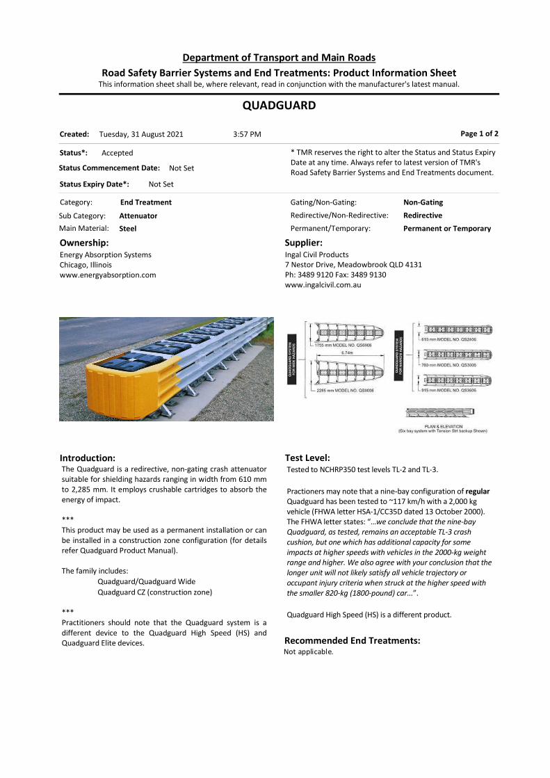
QUADGUARD
Category: End Treatment
Permanent/Temporary: Permanent or Temporary
Introduction:The Quadguard is a redirective, non-gating crash attenuator suitable for shielding hazards ranging in width from 610 mm to 2,285 mm. It employs crushable cartridges to absorb the energy of impact. *** This product may be used as a permanent installation or can be installed in a construction zone configuration (for details refer Quadguard Product Manual). The family includes:
Quadguard/Quadguard Wide Quadguard CZ (construction zone)
*** Practitioners should note that the Quadguard system is a different device to the Quadguard High Speed (HS) and Quadguard Elite devices.
Ownership:Energy Absorption SystemsChicago, Illinoiswww.energyabsorption.com
Supplier:Ingal Civil Products7 Nestor Drive, Meadowbrook QLD 4131Ph: 3489 9120 Fax: 3489 9130www.ingalcivil.com.au
Page 1 of 2
Test Level:Tested to NCHRP350 test levels TL-2 and TL-3. Practioners may note that a nine-bay configuration of regular Quadguard has been tested to ~117 km/h with a 2,000 kg vehicle (FHWA letter HSA-1/CC35D dated 13 October 2000). The FHWA letter states: “…we conclude that the nine-bay Quadguard, as tested, remains an acceptable TL-3 crash cushion, but one which has additional capacity for some impacts at higher speeds with vehicles in the 2000-kg weight range and higher. We also agree with your conclusion that the longer unit will not likely satisfy all vehicle trajectory or occupant injury criteria when struck at the higher speed with the smaller 820-kg (1800-pound) car...”. Quadguard High Speed (HS) is a different product.
Status*: Accepted
Status Commencement Date: Not Set
Status Expiry Date*: Not Set
* TMR reserves the right to alter the Status and Status Expiry Date at any time. Always refer to latest version of TMR's Road Safety Barrier Systems and End Treatments document.
Gating/Non-Gating: Non-Gating
Redirective/Non-Redirective: Redirective
Main Material: Steel
Sub Category: Attenuator
This information sheet shall be, where relevant, read in conjunction with the manufacturer's latest manual.Road Safety Barrier Systems and End Treatments: Product Information Sheet
Department of Transport and Main Roads
3:57 PMTuesday, 31 August 2021Created:
Recommended End Treatments:Not applicable.

Design:Design to be in accordance with the relevant Quadguard Product Manual provided by the supplier. Quadguard uses two types of crushable cartridge (Types I and II). System is available in various widths up to 2,285 mm. Designer to specify the number of bays and system width as appropriate for the impacts to be managed and the hazard to be shielded. In situations where traffic may approach the system in the reverse direction the appropriate transition arrangement should be specified by the designer. Design should provide for accommodation of any movement of side panels and other moving parts during impact. Designer should nominate required nose-markings.
Limitations:Should not be used on crossfalls steeper than 8%. Elevated kerbs, islands, drainage structures or any other item that can affect the height at which a vehicle could impact the unit should not be placed in advance of the unit or along the length of the unit.
QUADGUARD Page 2 of 2
References: AS/NZS 3845:1999 NCHRP Report 350 TMR Road Planning and Design Manual FHWA letters ref. CC-35 (various suffixes) Austroads Quadguard acceptance document (13 Apr
2015)
Austroads Quadguard WIDE acceptance document (30 Jun 2014)
Deflection:Not applicable.

QUADGUARD High Speed
Category: End Treatment
Permanent/Temporary: Permanent
Introduction:The Quadguard High Speed (HS) is a redirective, non-gating crash attenuator suitable for shielding hazards ranging in width from 610 mm to 2,285 mm. It employs crushable cartridges to absorb the energy of impact. *** Practitioners should note that this is a different system to the regular Quadguard system.
Ownership:Energy Absorption SystemsChicago, Illinoiswww.energyabsorption.com
Supplier:Ingal Civil Products7 Nestor Drive, Meadowbrook QLD 4131Ph: 3489 9120 Fax: 3489 9130www.ingalcivil.com.au
Page 1 of 2
Test Level:Tested to NCHRP Report 350 TL3+. Test Configuration, test vehicle and impact speed 3-31 2,000 kg utility 111.9 km/h 3-32 820 kg car 111.9 km/h 3-33 2,000 kg utility 115.5 km/h 3-36 820 kg car 113.7 km/h 3-37 2,000 kg utility 112.8 km/h 3-38 2,000 kg utility 114.6 km/h 3-39 2,000 kg utility 113.7 km/h
Status*: Accepted
Status Commencement Date: Not Set
Status Expiry Date*: Not Set
* TMR reserves the right to alter the Status and Status Expiry Date at any time. Always refer to latest version of TMR's Road Safety Barrier Systems and End Treatments document.
Gating/Non-Gating: Non-Gating
Redirective/Non-Redirective: Redirective
Main Material: Steel
Sub Category: Attenuator
This information sheet shall be, where relevant, read in conjunction with the manufacturer's latest manual.Road Safety Barrier Systems and End Treatments: Product Information Sheet
Department of Transport and Main Roads
3:57 PMTuesday, 31 August 2021Created:
Recommended End Treatments:Not Applicable.

Design:Design to be in accordance with the Quadguard HS Design Manual provided by the supplier. System is available in various widths up to 2,285 mm. Designer to specify the number of bays and system width as appropriate for the impacts to be managed and the hazard to be shielded. In situations where traffic may approach the system in the reverse direction the appropriate transition arrangement should be specified by the designer. Design should provide for accommodation of any movement of side panels and other moving parts during impact. Designer should nominate required nose-markings.
Limitations:Should not be used on crossfalls steeper than 8%. Elevated kerbs, islands, drainage structures or any other item that can affect the height at which a vehicle could impact the unit should not be placed in advance of the unit or along the length of the unit.
QUADGUARD High Speed Page 2 of 2
References: AS/NZS 3845:1999 NCHRP Report 350 Austroads acceptance document (15-Sep-2014) Trinity Quadguard HS Installation Manual (Rev. B 3/4/10) Trinity Quadguard HS Product Manual (Rev. A 02/25/10) FHWA letter ref. CC-35E (13 Oct 2000)
Deflection:Information has not been entered.

QUADGUARD ELITE
Category: End Treatment
Permanent/Temporary: Permanent
Introduction:The Quadguard Elite is a redirective, non-gating crash attenuator suitable for shielding hazards ranging in width from 610 mm to 2,285 mm. It employs energy absorbing cylinders to absorb the energy of impact. The product is similar in many ways to the basic Quadguard system except that the Quadguard Elite is highly reusable and is more suited to more frequent impacts. *** Practitioners should be aware that energy absorbing cylinders may retain residual energy after impact.
Ownership:Trinity Highway ProductsDallas, Texaswww.trinityhighway.com
Supplier:Ingal Civil Products7 Nestor Drive, Meadowbrook QLD 4131Ph: 3489 9120 Fax: 3489 9130www.ingalcivil.com.au
Page 1 of 2
Test Level:Tested to NCHRP350 test levels TL-2 and TL-3.
Status*: Accepted
Status Commencement Date: Not Set
Status Expiry Date*: Not Set
* TMR reserves the right to alter the Status and Status Expiry Date at any time. Always refer to latest version of TMR's Road Safety Barrier Systems and End Treatments document.
Gating/Non-Gating: Non-Gating
Redirective/Non-Redirective: Redirective
Main Material: Steel
Sub Category: Attenuator
This information sheet shall be, where relevant, read in conjunction with the manufacturer's latest manual.Road Safety Barrier Systems and End Treatments: Product Information Sheet
Department of Transport and Main Roads
3:57 PMTuesday, 31 August 2021Created:
Recommended End Treatments:Not Applicable.

Design:Design to be in accordance with the Quadguard Elite Design Manual provided by the supplier. System is available in various widths up to 2,285 mm. Designer to specify the number of bays and system width as appropriate for the impacts to be managed and the hazard to be shielded. In situations where traffic may approach the system in the reverse direction the appropriate transition arrangement should be specified by the designer. Design should provide for accommodation of any movement of side panels and other moving parts during impact. Designer should nominate required nose-markings.
*** Practitioners should be aware that energy absorbing cylinders may retain residual energy after impact.
Limitations:Should not be used on crossfalls steeper than 8%. Elevated kerbs, islands, drainage structures or any other item that can affect the height at which a vehicle could impact the unit should not be placed in advance of the unit or along the length of the unit.
QUADGUARD ELITE Page 2 of 2
References: AS/NZS 3845 NCHRP Report 350 QuadGuard Elite Product Manual (Rev F Aug 2014) QuadGuard Elite Assembly Manual (Rev F Aug 2014) Ingal Civil Products Manual Supplement (Dec 2015) FHWA letters CC-57 (various suffixes)
Deflection:Not applicable.
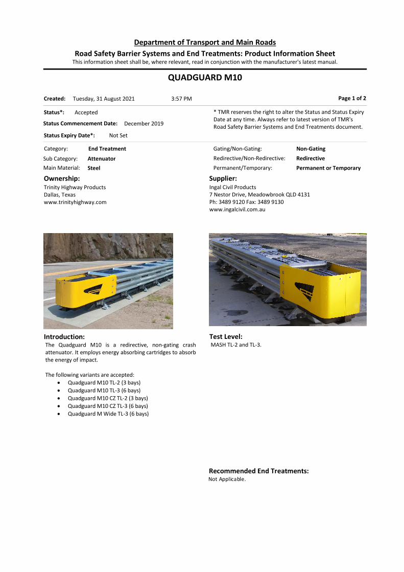
QUADGUARD M10
Category: End Treatment
Permanent/Temporary: Permanent or Temporary
Introduction:The Quadguard M10 is a redirective, non-gating crash attenuator. It employs energy absorbing cartridges to absorb the energy of impact. The following variants are accepted:
Quadguard M10 TL-2 (3 bays) Quadguard M10 TL-3 (6 bays) Quadguard M10 CZ TL-2 (3 bays) Quadguard M10 CZ TL-3 (6 bays) Quadguard M Wide TL-3 (6 bays)
Ownership:Trinity Highway ProductsDallas, Texaswww.trinityhighway.com
Supplier:Ingal Civil Products7 Nestor Drive, Meadowbrook QLD 4131Ph: 3489 9120 Fax: 3489 9130www.ingalcivil.com.au
Page 1 of 2
Test Level:MASH TL-2 and TL-3.
Status*: Accepted
Status Commencement Date: December 2019
Status Expiry Date*: Not Set
* TMR reserves the right to alter the Status and Status Expiry Date at any time. Always refer to latest version of TMR's Road Safety Barrier Systems and End Treatments document.
Gating/Non-Gating: Non-Gating
Redirective/Non-Redirective: Redirective
Main Material: Steel
Sub Category: Attenuator
This information sheet shall be, where relevant, read in conjunction with the manufacturer's latest manual.Road Safety Barrier Systems and End Treatments: Product Information Sheet
Department of Transport and Main Roads
3:57 PMTuesday, 31 August 2021Created:
Recommended End Treatments:Not Applicable.

Design:Design to be in accordance with the Quadguard M10 Product Manual provided by the supplier. The Quadguard M10 Systems are 610mm in width, and the Quadguard M Wide system is 1755mm in width. Designer to specify the number of bays as appropriate for the impacts to be managed and the hazard to be shielded. In situations where traffic may approach the system in the reverse direction the appropriate transition arrangement should be specified by the designer. Design should provide for accommodation of any movement of side panels and other moving parts during impact. Designer should nominate required nose-markings. The product may be temporarily installed in construction zones (referred as Quadguard M10 CZ) on 150mm asphaltic concrete over 150mm compacted sub-base permitted using M20 x 460mm Gr8.8 chemical anchor.
Limitations:Should not be used on crossfalls steeper than 8%. Elevated kerbs, islands, drainage structures or any other item that can affect the height at which a vehicle could impact the unit should not be placed in advance of the unit or along the length of the unit. Installation on unsealed compacted formation is not permitted.
QUADGUARD M10 Page 2 of 2
References: AS/NZS 3845 MASH 2016 Austroads Acceptance Documentation (10 Sep 2020) E-TECH MASH TL-3 Crash Test Reports (2010, 2011, and
2016) Applus IDIADA KARCO TL2 & TL-3 Crash Test Reports (2019)
Applus IDIADA KARCO Quadguard M Wide TL-3 Crash Test Reports (2020)
Quadguard M10 (24'' Wide) TL-2 & TL-3 Product Description Assembly Manual (Rev D, Nov 2019)
Quadguard M Wide Product Description Assembly Manual (May 2020)
Deflection:Not applicable.

QUADGUARD Elite M10
Category: End Treatment
Permanent/Temporary: Permanent
Introduction:The Quadguard Elite M10 is a redirective, non-gating crash attenuator. The system employs energy-absorbing high density polyethylene cylinders to absorb the energy of impact.
The product is similar in many ways to the basic Quadguard M10 system except that the Quadguard Elite is potentially reusable.
Ownership:Trinity Highway ProductsDallas, Texaswww.trinityhighway.com
Supplier:Ingal Civil Products7 Nestor Drive, Meadowbrook QLD 4131Ph: 3489 9120 Fax: 3489 9130www.ingalcivil.com.au
Page 1 of 2
Test Level:MASH TL-3.
Status*: Accepted
Status Commencement Date: July 2020
Status Expiry Date*: Not Set
* TMR reserves the right to alter the Status and Status Expiry Date at any time. Always refer to latest version of TMR's Road Safety Barrier Systems and End Treatments document.
Gating/Non-Gating: Non-Gating
Redirective/Non-Redirective: Redirective
Main Material: Steel
Sub Category: Attenuator
This information sheet shall be, where relevant, read in conjunction with the manufacturer's latest manual.Road Safety Barrier Systems and End Treatments: Product Information Sheet
Department of Transport and Main Roads
3:57 PMTuesday, 31 August 2021Created:
Recommended End Treatments:Not Applicable.

Design:Design to be in accordance with the Quadguard Elite M10 Product Manual provided by the supplier. The system is 610mm in width. In situations where traffic may approach the system in the reverse direction the appropriate transition arrangement should be specified by the designer. Design should provide for accommodation of any movement of side panels and other moving parts during impact. Designer should nominate required nose-markings.
*** Practitioners should be aware that energy absorbing cylinders may retain residual energy after impact.
Limitations:Should not be used on crossfalls steeper than 8%. Elevated kerbs, islands, drainage structures or any other item that can affect the height at which a vehicle could impact the unit should not be placed in advance of the unit or along the length of the unit.
QUADGUARD Elite M10 Page 2 of 2
References: AS/NZS 3845 MASH 2016 Austroads Terminal Technical Conditions for Use (19
June 2020) E-TECH MASH TL-3 Crash Test Results #376 (March
2011)
Applus IDIADA KARCO MASH TL-3 Test Reports TR-P39161-02NC, TR-P39162-01-NC, and TR-P39163-01-NC (9 December 2019, 3 December 2019)
Quadguard Elite M10 [24"] Product Description Assembly Manual (Revision B, June 2020)
Deflection:Not applicable.
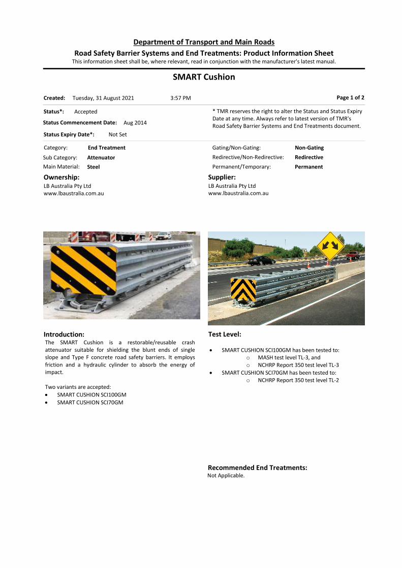
SMART Cushion
Category: End Treatment
Permanent/Temporary: Permanent
Introduction:The SMART Cushion is a restorable/reusable crash attenuator suitable for shielding the blunt ends of single slope and Type F concrete road safety barriers. It employs friction and a hydraulic cylinder to absorb the energy of impact. Two variants are accepted: SMART CUSHION SCI100GM SMART CUSHION SCI70GM
Ownership:LB Australia Pty Ltdwww.lbaustralia.com.au
Supplier:LB Australia Pty Ltdwww.lbaustralia.com.au
Page 1 of 2
Test Level:
SMART CUSHION SCI100GM has been tested to: o MASH test level TL-3, and o NCHRP Report 350 test level TL-3
SMART CUSHION SCI70GM has been tested to: o NCHRP Report 350 test level TL-2
Status*: Accepted
Status Commencement Date: Aug 2014
Status Expiry Date*: Not Set
* TMR reserves the right to alter the Status and Status Expiry Date at any time. Always refer to latest version of TMR's Road Safety Barrier Systems and End Treatments document.
Gating/Non-Gating: Non-Gating
Redirective/Non-Redirective: Redirective
Main Material: Steel
Sub Category: Attenuator
This information sheet shall be, where relevant, read in conjunction with the manufacturer's latest manual.Road Safety Barrier Systems and End Treatments: Product Information Sheet
Department of Transport and Main Roads
3:57 PMTuesday, 31 August 2021Created:
Recommended End Treatments:Not Applicable.
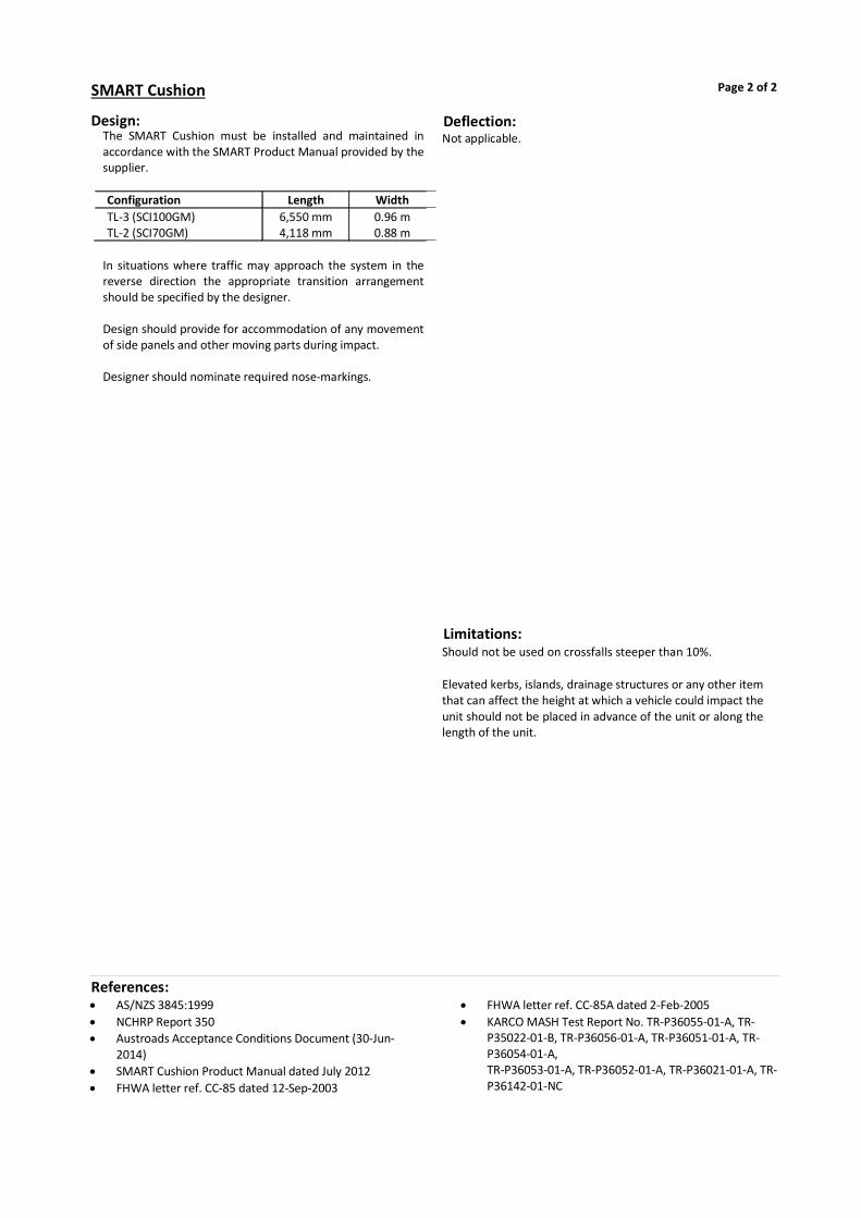
Design:The SMART Cushion must be installed and maintained in accordance with the SMART Product Manual provided by the supplier.
Configuration Length Width TL-3 (SCI100GM) 6,550 mm 0.96 m TL-2 (SCI70GM) 4,118 mm 0.88 m
In situations where traffic may approach the system in the reverse direction the appropriate transition arrangement should be specified by the designer. Design should provide for accommodation of any movement of side panels and other moving parts during impact. Designer should nominate required nose-markings.
Limitations:Should not be used on crossfalls steeper than 10%. Elevated kerbs, islands, drainage structures or any other item that can affect the height at which a vehicle could impact the unit should not be placed in advance of the unit or along the length of the unit.
SMART Cushion Page 2 of 2
References: AS/NZS 3845:1999 NCHRP Report 350 Austroads Acceptance Conditions Document (30-Jun-
2014) SMART Cushion Product Manual dated July 2012 FHWA letter ref. CC-85 dated 12-Sep-2003
FHWA letter ref. CC-85A dated 2-Feb-2005 KARCO MASH Test Report No. TR-P36055-01-A, TR-
P35022-01-B, TR-P36056-01-A, TR-P36051-01-A, TR-P36054-01-A, TR-P36053-01-A, TR-P36052-01-A, TR-P36021-01-A, TR-P36142-01-NC
Deflection:Not applicable.

TRACC
Category: End Treatment
Permanent/Temporary: Permanent
Introduction:The TRACC (Trinity Attenuating Crash Cushion) is a redirective, non-gating crash attenuator suitable for shielding hazards ranging in width from 610 mm to 1,470 mm. It employs a system of “rip plates” to absorb the energy of impact. The TRACC family comprises three variants:
TRACC FASTRACC WIDE TRACC
Ownership:Trinity Industries USAwww.highwayguardrail.com
Supplier:Ingal Civil Products7 Nestor Drive, Meadowbrook QLD 4131Ph: 3489 9120 Fax: 3489 9130www.ingalcivil.com.au
Page 1 of 2
Test Level:Standard TRACC is tested in accordance with NCHRP Report 350 to TL-2 and TL-3. WIDETRACC is deemed to have met the requirements of NCHRP Report 350 to TL-3 (FHWA letter CC-54D dated 5 Sep 2002). FHWA letter CC-54H dated 9 Jun 2005 notes that the longer FASTRACC has been tested with a 2,000 kg utility head-on at a speed of 112.2 km/h.
Status*: Accepted
Status Commencement Date: Not Set
Status Expiry Date*: Not Set
* TMR reserves the right to alter the Status and Status Expiry Date at any time. Always refer to latest version of TMR's Road Safety Barrier Systems and End Treatments document.
Gating/Non-Gating: Non-Gating
Redirective/Non-Redirective: Redirective
Main Material: Steel
Sub Category: Attenuator
This information sheet shall be, where relevant, read in conjunction with the manufacturer's latest manual.Road Safety Barrier Systems and End Treatments: Product Information Sheet
Department of Transport and Main Roads
3:57 PMTuesday, 31 August 2021Created:
Recommended End Treatments:Not Applicable.

Design:Design to be in accordance with the relevant TRACC Product Manual provided by the supplier.
Configuration Length Width TRACC TL-3 6.5 m 0.61 m TRACC TL-2 4.3 m 0.61 m
WIDETRACC system is available in various widths up to 1470 mm. FASTRACC differs from the TRACC system in length only. Effective length of FASTRACC is 7,925mm long compared to standard TRACC which is 6,477mm. Designer to specify configuration as appropriate for the impacts to be managed and the hazard to be shielded. In situations where traffic may approach the system in the reverse direction the appropriate transition arrangement should be specified by the designer. Design should provide for accommodation of any movement of side panels and other moving parts during impact. Designer should nominate required nose-markings.
Limitations:Should not be used on crossfalls steeper than 8%. Elevated kerbs, islands, drainage structures or any other item that can affect the height at which a vehicle could impact the unit should not be placed in advance of the unit or along the length of the unit.
TRACC Page 2 of 2
References: AS/NZS 3845:1999 NCHRP Report 350 TMR Road Planning and Design Manual Ingal Product Manual Release 004 NSW RMS TRACC acceptance document (05-Aug-2011)
NSW RMS WIDE TRACC acceptance document (05-Aug-2011)
NSW RMS FASTRACC acceptance document (13-Mar-2011)
FHWA letters CC-54 (various suffixes)
Deflection:Not applicable.

Universal TAU II
Category: End Treatment
Permanent/Temporary: Permanent or Temporary
Introduction:The Universal TAU-II is a proprietary redirective, non-gating crash attenuator for hazards ranging in width from 700 mm to 2,600 mm. It employs crushable cartridges to absorb the energy from impact. *** This product may be used as a permanent installation or can be installed in a construction zone configuration.
Ownership:Barrier Systems3333 Vaca Valley Pkwy, Ste. 800, Vacaville, CA 95688, USA www.barriersystemsinc.com
Supplier:Australian Construction Products (ACP)339 Horsley Road, Milperra, NSW 2214Ph. 1800 724 172www.acprod.com.au
Page 1 of 2
Test Level:Tested in accordance with NCHRP Report 350 to TL-2 and TL-3. FHWA letter CC-75A dated 20 Dec 2002 notes that a ten-bay (8978mm long) variant of the Universal TAU-II has been tested with a nominal 2,000 kg utility head-on at a speed of 109.4 km/h.
Status*: Accepted
Status Commencement Date: Not Set
Status Expiry Date*: Not Set
* TMR reserves the right to alter the Status and Status Expiry Date at any time. Always refer to latest version of TMR's Road Safety Barrier Systems and End Treatments document.
Gating/Non-Gating: Non-Gating
Redirective/Non-Redirective: Redirective
Main Material: Steel
Sub Category: Attenuator
This information sheet shall be, where relevant, read in conjunction with the manufacturer's latest manual.Road Safety Barrier Systems and End Treatments: Product Information Sheet
Department of Transport and Main Roads
3:57 PMTuesday, 31 August 2021Created:
Recommended End Treatments:Not Applicable.

Design:Design to be in accordance with the relevant Universal TAU-II Product Manual provided by the supplier.
Universal TAU-II uses two types of crushable cartridge (A & B).
System Bays with
Type A Bays with
Type B Universal TAU-II TL-3 1 3 Universal TAU-II TL-2 3 5
Universal TAU-II system is available in various widths up to 2,600 mm. Devices with more than one cartridge in the bay at the nose end of the system are not an accepted variant.
Designer to specify configuration as appropriate for the impacts to be managed and the hazard to be shielded. In situations where traffic may approach the system in the reverse direction the appropriate transition arrangement should be specified by the designer. Design should provide for accommodation of any movement of side panels and other moving parts during impact. Designer should nominate required nose-markings.
Limitations:Should not be used on crossfalls steeper than 8%. Elevated kerbs, islands, drainage structures or any other item that can affect the height at which a vehicle could impact the unit should not be placed in advance of the unit or along the length of the unit.
Universal TAU II Page 2 of 2
References: AS/NZS 3845 NCHRP Report 350 TMR Road Planning and Design Manual Austroads acceptance document dated 30 March 2016 FHWA letters CC-75 (various suffixes)
Deflection:Not applicable.

Universal TAU-M
Category: End Treatment
Permanent/Temporary: Permanent
Introduction:The Universal TAU-M is a proprietary redirective, non-gating crash attenuator for hazards up to 762mm in width. It employs crushable cartridges to absorb the energy from impact.
Ownership:Lindsay Transportation Solutions 180 River Road, Rio Vista, CA 94571, USAPh: +1 (707) 374 6800www.lindsaytransportationsolutions.com
Supplier:Australian Construction Products (ACP)339 Horsley Road, Milperra, NSW 2214Ph: +61 2 8708 4400www.acprod.com.au
Page 1 of 2
Test Level:MASH TL-2 & TL-3.
Status*: Accepted
Status Commencement Date: December 2019
Status Expiry Date*: Not Set
* TMR reserves the right to alter the Status and Status Expiry Date at any time. Always refer to latest version of TMR's Road Safety Barrier Systems and End Treatments document.
Gating/Non-Gating: Non-Gating
Redirective/Non-Redirective: Redirective
Main Material: Steel
Sub Category: Attenuator
This information sheet shall be, where relevant, read in conjunction with the manufacturer's latest manual.Road Safety Barrier Systems and End Treatments: Product Information Sheet
Department of Transport and Main Roads
3:57 PMTuesday, 31 August 2021Created:
Recommended End Treatments:Not Applicable.

Design:Design to be in accordance with the relevant Universal TAU-M Product Manual provided by the supplier. Universal TAU-M system varies in system length depending on test level.
System Number of Bay Length Universal TAU-M TL-3 7 7.3m Universal TAU-M TL-2 4 4.7m
Design should provide for accommodation of any movement of side panels and other moving parts during impact. Designer should nominate required nose-markings. Pavement: Concrete and asphalt pavement foundations are permitted. Consult the supplier for details.
Limitations:Should not be used on crossfalls steeper than 7%. Single sided transition panel may be permitted and required where reverse impacts are possible. Reverse impacts into the transition section can produce a greater occupant severity value than preferred. Where reverse impacts are possible (e.g. bidirectional traffic) a risk assessment must be completed and steps to mitigate the likelihood of reverse impact should be implemented. Installation on top of a kerb is not recommended, however if installed on top of a kerb all system components must be free to operate.
Universal TAU-M Page 2 of 2
References: MASH 2016 AS/NZS 3845 Universal TAU-M Installation Instructions (Rev A,
10/01/2018) ASBAP Technical Conditions for Use (4 Mar 2021)
Universal TAU-M TL-2 Test Reports (Test 2-30, 2-31, 2-32, 2-33, 2-34, 2-35, and 2-37a) (Safe Technologies Inc., 2018)
Universal TAU-M TL-3 Test Reports (Test 3-30, 3-31, 3-32, 3-33, 3-34, 3-35, 3-36 and 3-37a) (Safe Technologies Inc., 2018)
Deflection:Not applicable.

Precast Concrete Barrier (PCB)TMR Standard Drawing 1473
Category: Longitudinal
Permanent/Temporary: Permanent or Temporary
Introduction:The Precast Concrete Barrier (PCB) is a concrete barrier with a single-slope profile. Useful Product Data: Unit length - 7250mm Unit width (base) - 620mm Unit height - 1050mm Note limitations regarding lifting: seek latest advice from TMR Structures Branch
Ownership:Public Domain
Supplier:Various
Page 1 of 2
Test Level:Deemed to meet the requirements of NCHRP report 350 test level TL-3 when properly connected in accordance with QTMR standard drawing 1473.
Status*: Accepted
Status Commencement Date: Not Set
Status Expiry Date*: Not Set
* TMR reserves the right to alter the Status and Status Expiry Date at any time. Always refer to latest version of TMR's Road Safety Barrier Systems and End Treatments document.
Gating/Non-Gating: Not Applicable
Redirective/Non-Redirective: Redirective
Main Material: Concrete
Sub Category: Semi-Rigid
This information sheet shall be, where relevant, read in conjunction with the manufacturer's latest manual.Road Safety Barrier Systems and End Treatments: Product Information Sheet
Department of Transport and Main Roads
3:57 PMTuesday, 31 August 2021Created:
Recommended End Treatments:Quadguard CZ; TAU II; Triton CET (<=70km/h); SLED (<=80km/h); Absorb 350 (<=70km/h): (requires transition in concrete barrier to maximum height of 812mm); Absorb-M (<=80km/h)

Design:Minimum Length: 36 m Recommended Minimum Radius: R150m Interaction with Kerbs In unrestrained configurations, the system cannot be
placed adjacent to kerbs or other objects within the deflection limits of the barrier that may prevent lateral displacement.
End Treatments: A proprietary end treatment should be installed
wherever any risk exists that the blunt end could be impacted.
Any proprietary end treatment system must be specifically designed or adapted for use with “single slope” shape barrier and must be installed and maintained strictly in accordance with the manufacturer’s instructions.
Barrier flare rate should not exceed 1:10. Vehicle Roll: Where the hazard being protected by a barrier extends
above the height of the barrier the Designer should ensure that adequate separation from the face of the barrier to the hazard is provided to allow for the roll of high vehicles (such as trucks) hitting the hazard.
Limitations: Refer TMR std. dwg. 1473 [Check for currency of
revision]. Placement of barriers and effects on surface drainage
are to be considered.
Maintenance: Inspect units for damage after impact. Damaged units
to be replaced.
Precast Concrete Barrier (PCB) Page 2 of 2
References: Australian Standard AS/NZS 3845 NCHRP Report 350 TMR Road Planning and Design Manual Main Roads Standard Drawing 1473 (rev. F)
Beason et al (1989) Development of a Single Slope Concrete Median Barrier, TTI
Barrier Systems Inc letter dated 23 March 2004 Email correspondence on SLED transition to PCB
(Saferoads, 18 December 2019)
Deflection:Deflection (Normal Design Domain): Measured (Crash Test) Deflections: Nominal
Mass (kg)
Nominal Angle (deg)
Nominal Speed (km/h)
Recorded Deflection
(m)
Note
2000 15 100 0.18 1 2000 15 100 0.15 2
Notes: 1. Beason et al (1989) test ref. 9429C-1, 36.4m installation (4
x 9.1m units) 2. Beason et al (1989) test ref. 9429K-1, 54.6m installation (6
x 9.1m units) Actual clearance distance to workzone should be determined by risk assessment prior to installation. Designers are recommended to adopt the largest working width / deflection value for the nominated containment level.

DB80 K150
Category: Longitudinal
Permanent/Temporary: Temporary
Introduction:DB80 K150 is an F-shape steel reinforced concrete temporary barrier with K150 tension bar coupling system and joint rotation limiting wedges (“butt inserts”). Variants accepted are: 2m unit (see Limitations) 4m unit 6m unit The variants NOT accepted are: Systems with intermediate ground attachment Systems without joint rotation limiting wedges Profiles other than F-shape.
Ownership:Deltabloc International28 Industristrase, Sollenau, 2601, Austriawww.deltabloc.com/en
Supplier:Orange Hire 22 Hugh St, Pinkenba QLD 4008www.orangehire.com.au
Page 1 of 2
Test Level:4m units are demonstrated to meet the requirements of MASH TL-3. Note that ‘F’ type profile concrete barriers are only accepted for use on state-controlled roads in Queensland where the speed limit is 80 km/h or lower.
Status*: Accepted
Status Commencement Date: Not Set
Status Expiry Date*: Not Set
* TMR reserves the right to alter the Status and Status Expiry Date at any time. Always refer to latest version of TMR's Road Safety Barrier Systems and End Treatments document.
Gating/Non-Gating: Not Applicable
Redirective/Non-Redirective: Redirective
Main Material: Concrete
Sub Category: Semi-Rigid
This information sheet shall be, where relevant, read in conjunction with the manufacturer's latest manual.Road Safety Barrier Systems and End Treatments: Product Information Sheet
Department of Transport and Main Roads
3:57 PMTuesday, 31 August 2021Created:
Recommended End Treatments:Tau II; Quadguard CZ; Absorb 350 (<=70km/hr); Absorb-M (<=80km/hr); SLED (<=80km/hr); SMART Cushion; Universal TAU-M.

Design:Designers should note that deflection and capacity are a function of the tension bar connectors between units. Barrier flare rate should not exceed 1:10. Seek advice from supplier on site specific requirements. The tension bar for this system is the K150. Point of Redirection: Point of redirection is 29.2m from the interface between the terminal and the barrier. Interaction with Kerbs: Barriers should be placed at the same level as the
travelling surface and should not be placed behind or on top of kerbing.
If placed in front of kerbs, maximum expected deflection distance between face of kerb and back of barrier must be maintained.
End Treatments: A proprietary end treatment should be installed
wherever any risk exists that the blunt end could be impacted.
Any proprietary end treatment system must be specifically designed or adapted for use with “F” type barriers and must be installed and maintained strictly in accordance with the manufacturer’s instructions.
Supplier should be contacted for details of connection to an anchored crash cushion. If units are freestanding, then the system is not effective from the nose of the cushion and possibility of reverse direction impacts is to be considered. The DB80 K150 barrier adjacent to any redirective crash cushion must be anchored to the pavement as required by the product manual.
Accepted end treatments are not permitted to be used on a flare.
Maintenance: Units may need to be repaired or replaced after impact depending on the extent of damage. Minimum Length of Barrier: Designer to consult supplier for minimum length of barrier.
Limitations:Sloped end terminals are not permitted. Note that 2m units are available to be used only to resolve difficult geometric configurations such as tight radius curves and emergency openings. Designer must be cognisant that shorter units may have increased deflection characteristics and lower containment capacity. Seek advice from supplier.
DB80 K150 Page 2 of 2
References: Australian Standard AS/NZS 3845 MASH 2016 TMR Road Planning and Design Manual Austroads Acceptance Documents (20/07/2021) MwRSF report ref. TRP-030245-10
DB 80 F-Shape Installation Manual (Rev 02c, 25/06/2021)
Deflection:Deflection (Normal Design Domain): Measured (Crash Test) Deflections:
Nominal Mass (kg)
Nominal Angle (deg)
Nominal Speed (km/h)
Recorded Deflection
(m)
Working Width (m)
1100 1 25 100 0.57 1.15 2270 1 25 100 1.44 1.94
Note: 1. MwRSF report ref. TRP-030245-10 (2010), 4m units Actual clearance distance to workzone should be determined by risk assessment prior to installation. Designers are recommended to adopt the largest working width / deflection value for the nominated containment level.

J-J Hooks
Category: Longitudinal
Permanent/Temporary: Temporary
Introduction:J-J Hooks is a temporary concrete barrier system which has an ‘F’ type profile. Useful Product Data 3.6 metre barrier unit, 2.5 tonnes 6.0 metre barrier unit, 4.3 tonnes
Ownership:Easi-Set IndustriesMidland Virginia
Supplier:Australian Road BarriersRMB H535, Old Creswick Rd, Ballarat Victoria 3352Ph: 1800 003 826 Fax: (03) 5339 9273www.roadbarriers.com.au
Page 1 of 2
Test Level:Partially tested (capacity test only) in accordance with AS/NZS 3845 to NCHRP 350 TL-3. Note that Type ‘F’ profile concrete barriers are only accepted for use on state-controlled roads in Queensland where the speed limit is 80 km/h or lower.
Status*: Accepted
Status Commencement Date: Not Set
Status Expiry Date*: Not Set
* TMR reserves the right to alter the Status and Status Expiry Date at any time. Always refer to latest version of TMR's Road Safety Barrier Systems and End Treatments document.
Gating/Non-Gating: Not Applicable
Redirective/Non-Redirective: Redirective
Main Material: Concrete
Sub Category: Semi-Rigid
This information sheet shall be, where relevant, read in conjunction with the manufacturer's latest manual.Road Safety Barrier Systems and End Treatments: Product Information Sheet
Department of Transport and Main Roads
3:57 PMTuesday, 31 August 2021Created:
Recommended End Treatments:Absorb 350 (<=70km/hr); Quadguard CZ, SLED.
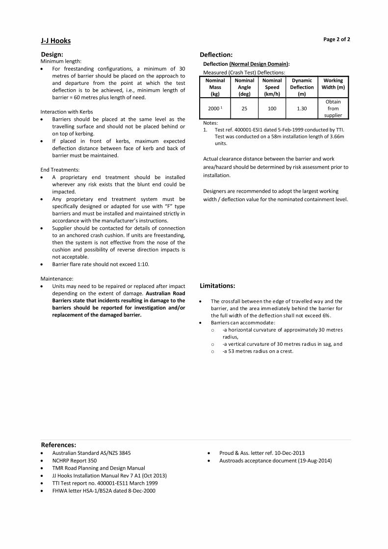
Design:Minimum length: For freestanding configurations, a minimum of 30
metres of barrier should be placed on the approach to and departure from the point at which the test deflection is to be achieved, i.e., minimum length of barrier = 60 metres plus length of need.
Interaction with Kerbs Barriers should be placed at the same level as the
travelling surface and should not be placed behind or on top of kerbing.
If placed in front of kerbs, maximum expected deflection distance between face of kerb and back of barrier must be maintained.
End Treatments: A proprietary end treatment should be installed
wherever any risk exists that the blunt end could be impacted.
Any proprietary end treatment system must be specifically designed or adapted for use with “F” type barriers and must be installed and maintained strictly in accordance with the manufacturer’s instructions.
Supplier should be contacted for details of connection to an anchored crash cushion. If units are freestanding, then the system is not effective from the nose of the cushion and possibility of reverse direction impacts is not acceptable.
Barrier flare rate should not exceed 1:10. Maintenance: Units may need to be repaired or replaced after impact
depending on the extent of damage. Australian Road Barriers state that incidents resulting in damage to the barriers should be reported for investigation and/or replacement of the damaged barrier.
Limitations: The crossfall between the edge of travelled way and the
barrier, and the area immediately behind the barrier for the full width of the deflection shall not exceed 6%.
Barriers can accommodate: o -a horizontal curvature of approximately 30 metres
radius, o -a vertical curvature of 30 metres radius in sag, and o -a 53 metres radius on a crest.
J-J Hooks Page 2 of 2
References: Australian Standard AS/NZS 3845 NCHRP Report 350 TMR Road Planning and Design Manual JJ Hooks Installation Manual Rev 7 A1 (Oct 2013) TTI Test report no. 400001-ES11 March 1999 FHWA letter HSA-1/B52A dated 8-Dec-2000
Proud & Ass. letter ref. 10-Dec-2013 Austroads acceptance document (19-Aug-2014)
Deflection:Deflection (Normal Design Domain): Measured (Crash Test) Deflections: Nominal
Mass (kg)
Nominal Angle (deg)
Nominal Speed (km/h)
Dynamic Deflection
(m)
Working Width (m)
2000 1 25 100 1.30 Obtain from
supplier Notes: 1. Test ref. 400001-ESI1 dated 5-Feb-1999 conducted by TTI.
Test was conducted on a 58m installation length of 3.66m units.
Actual clearance distance between the barrier and work area/hazard should be determined by risk assessment prior to installation. Designers are recommended to adopt the largest working width / deflection value for the nominated containment level.

JJ Hooks MASH
Category: Longitudinal
Permanent/Temporary: Temporary
Introduction:JJ Hooks MASH is a temporary freestanding concrete barrier system which has an ‘F’ type profile. JJ Hooks MASH is available in the following variants: 3.6 metre barrier unit 6.0 metre barrier unit
Ownership:Easi-Set IndustriesMidland Virginia
Supplier:Australian Road BarriersRMB H535, Old Creswick Rd, Ballarat Victoria 3352Ph: 1800 003 826 Fax: (03) 5339 9273www.roadbarriers.com.au
Page 1 of 2
Test Level:MASH TL-3. Note that Type ‘F’ profile concrete barriers are only accepted for use on state-controlled roads in Queensland where the speed limit is 80 km/h or lower.
Status*: Accepted
Status Commencement Date: February 2021
Status Expiry Date*: Not Set
* TMR reserves the right to alter the Status and Status Expiry Date at any time. Always refer to latest version of TMR's Road Safety Barrier Systems and End Treatments document.
Gating/Non-Gating: Not Applicable
Redirective/Non-Redirective: Redirective
Main Material: Concrete
Sub Category: Semi-Rigid
This information sheet shall be, where relevant, read in conjunction with the manufacturer's latest manual.Road Safety Barrier Systems and End Treatments: Product Information Sheet
Department of Transport and Main Roads
3:57 PMTuesday, 31 August 2021Created:
Recommended End Treatments:For 3.6m JJ Hooks MASH: Absorb 350 (<=70km/h), Absorb M (<=80km/h); For 6m JJ Hooks MASH: SMART Cushion, Absorb 350 (<=70km/h), Quadguard CZ, Universal TAU-M, SLED (<=80km/h), Absorb-M (<=80km/h), Quadguard M10 CZ (Forward direction application only).

Design:Point of Need: The JJ Hooks MASH 3.6m system is considered to be re-directive 28.8m from leading and trailing ends. The JJ Hooks 6m system system is considered to be re-directive 33m from leading and trailing ends. Pavement: The JJ Hooks MASH 3.6m system was tested on a concrete surface, while the JJ Hooks MASH 6m system was teste on an asphalt concrete surface. Additional pavement conditions have been permitted by Austroads Safety Barrier Assessment Panel, consult the supplier for full details of permitted foundation pavement conditions. Minimum Length of Barrier:
System MASH Test Level
Minimum Length (m)
3.6m TL-3 59 6m TL-3 66
Limitations: The crossfall between the edge of travelled way and the
barrier, and the area immediately behind the barrier for the full width of the deflection shall not exceed 6%.
Installation on top of a kerb is not recommended.
JJ Hooks MASH Page 2 of 2
References: Australian Standard AS/NZS 3845 Austroads acceptance document (20 Nov 2020; 1 Dec
2020) JJ Hooks Freestanding 3.6m Concrete Safety Barrier
Installation & Maintenance Instructions (Oct/Nov 2020)
JJ Hooks Concrete Safety Barrier Installation & Maintenance Instructions (Apr 2020)
TTI MASH Test 3-10 of 3.6m JJ Hooks Report (Jan 2018) TTI MASH Test 3-11 of 3.6m JJ Hooks Report (Jan 2017) Holmes Solutions - MASH Compliance Testing of 6m JJ
Hooks Report (June 2018)
Deflection:Deflection (Normal Design Domain): Measured (Crash Test) Deflections:
System Type
Nominal Mass (kg)
Nominal Angle (deg)
Nominal Speed (km/h)
Recorded Deflection
(m)
Working Width
(m)
3.6m 1,1001 25 100 0.67 1.27 2,2701 25 100 1.63 2.23
6m 1,1002 25 100 0.82 1.42 2,2702 25 100 1.6 2.2
Notes: 1. JJ Hooks 3.6m Concrete Safety Barrier MASH TL-3 compliance
testing 2. JJ Hooks 6m Concrete Safety Barrier MASH TL-3 compliance testing Actual clearance distance between the barrier and work area/ hazard should be determined by risk assessment prior to installation. Designers are recommended to adopt the largest working width / deflection value for the nominated containment level.

T-LOK
Category: Longitudinal
Permanent/Temporary: Temporary
Introduction:T-Lok is a semi-rigid temporary concrete barrier system which has a Type F profile. Two variants are accepted for use:
T-Lok MASH T-Lok 350
Installations shall comprise either but not both types of units. Useful Product Data
• Unit height 810mm • Unit width (base) 610mm • 3.6 metre barrier unit, 2.6 tonnes • 5.4 metre barrier unit, 3.9 tonnes
Ownership:Rockingham Pre-Cast
Supplier:Saferoads39 Weerong RoadDrouin VIC 3818Ph: (03) 5625 6600Fax: (03) 5625 4986www.saferoads.com.au
Page 1 of 2
Test Level:Two variants are accepted: T-Lok 350 tested to NCHRP report 350 test level TL-3. T-Lok MASH tested to MASH test level TL-3. Note that Type ‘F’ profile concrete barriers are only accepted for use on state-controlled roads in Queensland where the speed limit is 80 km/h or lower.
Status*: Accepted
Status Commencement Date: Not Set
Status Expiry Date*: Not Set
* TMR reserves the right to alter the Status and Status Expiry Date at any time. Always refer to latest version of TMR's Road Safety Barrier Systems and End Treatments document.
Gating/Non-Gating: Not Applicable
Redirective/Non-Redirective: Redirective
Main Material: Concrete
Sub Category: Semi-Rigid
This information sheet shall be, where relevant, read in conjunction with the manufacturer's latest manual.Road Safety Barrier Systems and End Treatments: Product Information Sheet
Department of Transport and Main Roads
3:57 PMTuesday, 31 August 2021Created:
Recommended End Treatments:Quadguard CZ; SLED.
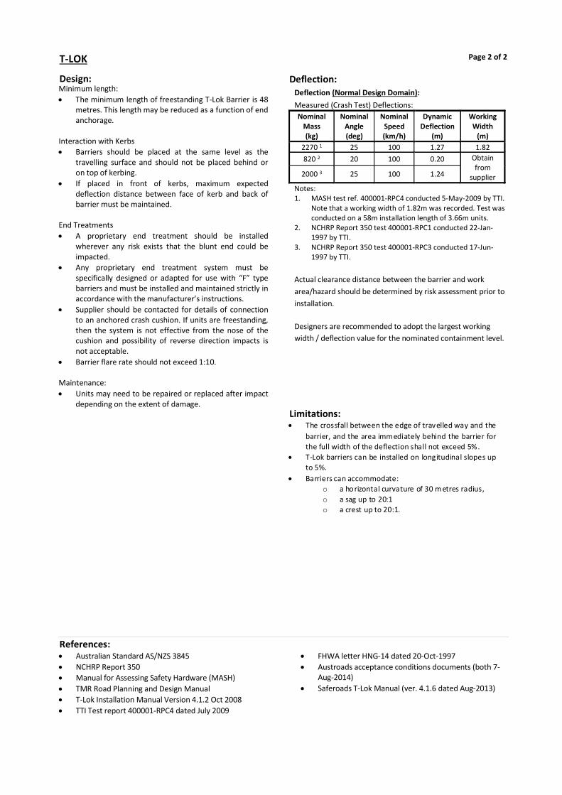
Design:Minimum length: The minimum length of freestanding T-Lok Barrier is 48
metres. This length may be reduced as a function of end anchorage.
Interaction with Kerbs Barriers should be placed at the same level as the
travelling surface and should not be placed behind or on top of kerbing.
If placed in front of kerbs, maximum expected deflection distance between face of kerb and back of barrier must be maintained.
End Treatments A proprietary end treatment should be installed
wherever any risk exists that the blunt end could be impacted.
Any proprietary end treatment system must be specifically designed or adapted for use with “F” type barriers and must be installed and maintained strictly in accordance with the manufacturer’s instructions.
Supplier should be contacted for details of connection to an anchored crash cushion. If units are freestanding, then the system is not effective from the nose of the cushion and possibility of reverse direction impacts is not acceptable.
Barrier flare rate should not exceed 1:10. Maintenance: Units may need to be repaired or replaced after impact
depending on the extent of damage. Limitations:
The crossfall between the edge of travelled way and the barrier, and the area immediately behind the barrier for the full width of the deflection shall not exceed 5%.
T-Lok barriers can be installed on longitudinal slopes up to 5%.
Barriers can accommodate: o a horizontal curvature of 30 m etres radius, o a sag up to 20:1 o a crest up to 20:1.
T-LOK Page 2 of 2
References: Australian Standard AS/NZS 3845 NCHRP Report 350 Manual for Assessing Safety Hardware (MASH) TMR Road Planning and Design Manual T-Lok Installation Manual Version 4.1.2 Oct 2008 TTI Test report 400001-RPC4 dated July 2009
FHWA letter HNG-14 dated 20-Oct-1997 Austroads acceptance conditions documents (both 7-
Aug-2014) Saferoads T-Lok Manual (ver. 4.1.6 dated Aug-2013)
Deflection:Deflection (Normal Design Domain): Measured (Crash Test) Deflections: Nominal
Mass (kg)
Nominal Angle (deg)
Nominal Speed (km/h)
Dynamic Deflection
(m)
Working Width
(m) 2270 1 25 100 1.27 1.82 820 2 20 100 0.20 Obtain
from supplier 2000 3 25 100 1.24
Notes: 1. MASH test ref. 400001-RPC4 conducted 5-May-2009 by TTI.
Note that a working width of 1.82m was recorded. Test was conducted on a 58m installation length of 3.66m units.
2. NCHRP Report 350 test 400001-RPC1 conducted 22-Jan-1997 by TTI.
3. NCHRP Report 350 test 400001-RPC3 conducted 17-Jun-1997 by TTI.
Actual clearance distance between the barrier and work area/hazard should be determined by risk assessment prior to installation. Designers are recommended to adopt the largest working width / deflection value for the nominated containment level.

Pin and Loop
Category: Longitudinal
Permanent/Temporary: Temporary
Introduction:Pin and Loop is a semi-rigid temporary concrete barrier system which has a Type F profile. Useful Product Data
• Unit height 810mm • Unit width (base) 610mm • 3.81 metre long barrier unit • 2.85 tonne barrier unit
Ownership:Retsel Holdings Pty Ltd63-69 High StreetQueanbeyan NSW 2620Ph: (02) 6297 1611www.precastconcrete.com.au
Supplier:Pin and Loop Pty Ltd63-69 High StreetQueanbeyan NSW 2620Ph: (02) 6297 1611www.precastconcrete.com.au
Page 1 of 2
Test Level:MASH TL3 Note that Type ‘F’ profile concrete barriers are only accepted for use on state-controlled roads in Queensland where the speed limit is 80 km/h or lower.
Status*: Accepted
Status Commencement Date: Not Set
Status Expiry Date*: Not Set
* TMR reserves the right to alter the Status and Status Expiry Date at any time. Always refer to latest version of TMR's Road Safety Barrier Systems and End Treatments document.
Gating/Non-Gating: Not Applicable
Redirective/Non-Redirective: Redirective
Main Material: Concrete
Sub Category: Semi-Rigid
This information sheet shall be, where relevant, read in conjunction with the manufacturer's latest manual.Road Safety Barrier Systems and End Treatments: Product Information Sheet
Department of Transport and Main Roads
3:57 PMTuesday, 31 August 2021Created:
Recommended End Treatments:TAU-II ABSORB350 (<= 70km/h)

Design:General: The Pin and Loop barrier system consists of freestanding 3.81 metre long units, interconnected by a pin and loop connection system. No footings or anchors are required. Point of Need: Pin and Loop is considered to be redirective at 21.77 metres from the leading end and 39.47 metres from the trailing end Pavement: This system requires a minimum bearing capacity of 200kN/m2 Minimum Length of Barrier:
System MASH Test Level
Minimum Length (m)
Note
Pin and Loop TL3 61.4 1 Notes:
1. Not including terminals.
Limitations: The crossfall between the edge of travelled way and the
barrier, and the area immediately behind the barrier for the full width of the deflection shall not exceed 7%
Barriers can accommodate a horizontal curvature radius of greater than or equal to 235 metres. Refer to the product manual and the supplier for vertical curvature limitations.
Pin and Loop Page 2 of 2
References: MASH 2016 Austroads acceptance documents (20 May 2019) Product manual (Ver. 1 Rev 1 - 5 September 2019) Pin and Loop Design drawing (Rev1 November 2018)
Product specification (November 2018) Test Report 607911-1 (May 2017) Test Report 607911-2 (May 2017)
Deflection:Deflection (Normal Design Domain): Measured (Crash Test) Deflections:
Nominal Mass (kg)
Nominal Angle (deg)
Nominal Speed (km/h)
Recorded Deflection
(m)
Working Width
(m) 11001 25 100 0.92 1.54 22702 25 100 1.61 2.22
Notes: 1. MASH 3-10 test 2. MASH 3-11 test
Actual clearance distance between the barrier and work area/hazard should be determined by risk assessment prior to installation. Designers are recommended to adopt the largest working width / deflection value for the nominated containment level.

BG800
Category: Longitudinal
Permanent/Temporary: Permanent or Temporary
Introduction:BG800 is a steel semi-rigid portable steel safety barrier system which may be deployed in either temporary or permanent configurations. BG800 is available in the following variants: BG800 Standard BG800 MDS (Minimum Deflection System) BG800 LDS (Limited Deflection System) Major components comprise: 12m units and 6m longitudinal barrier units. Anchored terminal end units. Short radius units (0.61m).
Ownership:Highway Care Internationalhttp://www.highwaycare.com
Supplier:Ingal Civil Products7 Nestor Drive, Meadowbrook QLD 4131Ph: 3489 9120 Fax: 3489 9130www.ingalcivil.com.au
Page 1 of 2
Test Level:Standard System: NCHRP Report 350 TL-2, TL-3 and TL-4 and MASH TL-3. Limited Deflection System (LDS): NCHRP Report 350 TL-3 and TL-4. Minimum Deflection System (MDS): NCHRP Report 350 TL-3.
Status*: Accepted
Status Commencement Date: December 2019
Status Expiry Date*: Not Set
* TMR reserves the right to alter the Status and Status Expiry Date at any time. Always refer to latest version of TMR's Road Safety Barrier Systems and End Treatments document.
Gating/Non-Gating: Not Applicable
Redirective/Non-Redirective: Redirective
Main Material: Steel
Sub Category: Semi-Rigid
This information sheet shall be, where relevant, read in conjunction with the manufacturer's latest manual.Road Safety Barrier Systems and End Treatments: Product Information Sheet
Department of Transport and Main Roads
3:57 PMTuesday, 31 August 2021Created:
Recommended End Treatments:Quadguard CZ; SMART Cushion; Universal Tau II; Absorb 350 (<=70km/h, for temporary use only); Absorb-M (<=80km/h, for temporary use only). (See respective product information sheets.) Note that flaring outside the clear-zone and ramped ends are not accepted end treatment solutions.

Design:General BG800 has the following variants: i) The standard configuration has end anchors and
intermediate anchors at 60m spacing. ii) The LDS configuration has end anchors and intermediate
anchors at 12m spacing. iii) The MDS configuration has end anchors and intermediate
anchors at 6m spacing. It also requires the addition of T-Top sections to the top of the barrier.
BG800 Standard can be connected to HighwayGuard LDS. Minimum Length: Barrier length requirements should be determined by
the “Length of Need” methodology. Standard System: 60 m between anchors. Limited Deflection System (LDS): 60 m, Minimum Deflection System (MDS): 48 m. Anchor Spacings/Deflections: Standard system: Maximum anchor spacing is
nominated as 480 m. Closer anchor spacing (60 m) would be required to replicate test conditions. Designers should consider that, for the same impact, wider anchor spacing will result in greater deflections, and that closer anchor spacing will result in smaller deflections.
Limited deflection system: Anchor spacing = 12m. Minimum deflection system: Anchor spacing = 6m. Offset from Trafficked Lane: The offset between the barrier and the travelled lane
should be not less than 500 mm. Flare rates shall be as per TMR Road Planning & Design
Manual. Interaction with Kerbs: Cannot be placed adjacent to kerbs or other objects
within the deflection limits of the barrier, which may prevent lateral displacement.
Vehicle Roll: Where the hazard being protected by a barrier extends
above the height of the barrier the Designer should ensure that adequate separation from the face of the barrier to the hazard is provided to allow for the roll of high vehicles (such as trucks) hitting the hazard.
Maintenance: Units may need to be repaired or replaced after impact
depending on the extent of damage.
Limitations: The crossfall between the edge of travelled way and the
barrier should not exceed 8%. Special units may be required for small radius curves.
BG800 Page 2 of 2
References: NCHRP Report 350 & MASH BG800 Australia & New Zealand Product and
Installation Manual (Rev. F – 11/20) Austroads acceptance documents (Permanent) (23 Mar
2021) Austroads acceptance documents (MDS - Temporary) (4
Mar 2021)
Austroads acceptance documents (Temporary) (23 Mar 2021)
Austroads acceptance documents (LDS) (4 Mar 2021)
Deflection:Deflection (Normal Design Domain): Measured (Crash Test) Deflections:
Notes: 1. MASH TL-3 (Test#BG1302) 2. NCHRP Report 350 TL-4 (Test#P0206) 3. NCHRP Report 350 TL-3 (Test#BG1303) 4. NCHRP Report 350 TL-2 (Test#1506) 5. NCHRP Report 350 TL-3 (Test#BG804) 6. NCHRP Report 350 TL-4 (Test#P0252) 7. NCHRP Report 350 TL-3 (Test#BG808)
Actual clearance distance between barrier and work area/hazard should be determined by risk assessment. Designers are recommended to adopt the largest working width/ deflection value for the nominated containment level.
System Type Nominal
Mass (kg)
Nominal Angle (deg)
Nominal Speed (km/h)
Recorded Deflection
(m)
Working Width
(m) Standard
60m anchor spacing 1
2270 25 100 1.66 2.2
Standard 60m anchor
spacing 2 8000 15 80 1.74
Obtain from
supplier
Standard 60m anchor
spacing 3 2000 25 100 1.60
Standard 60m anchor
spacing 4 2000 25 70 1.36
LDS 12m anchor
spacing 5 2000 25 100 0.89
LDS 12m anchor
spacing 6 8000 15 80 0.42
MDS 6m anchor spacing 7
2000 25 100 0.305 Top 0.076 Toe
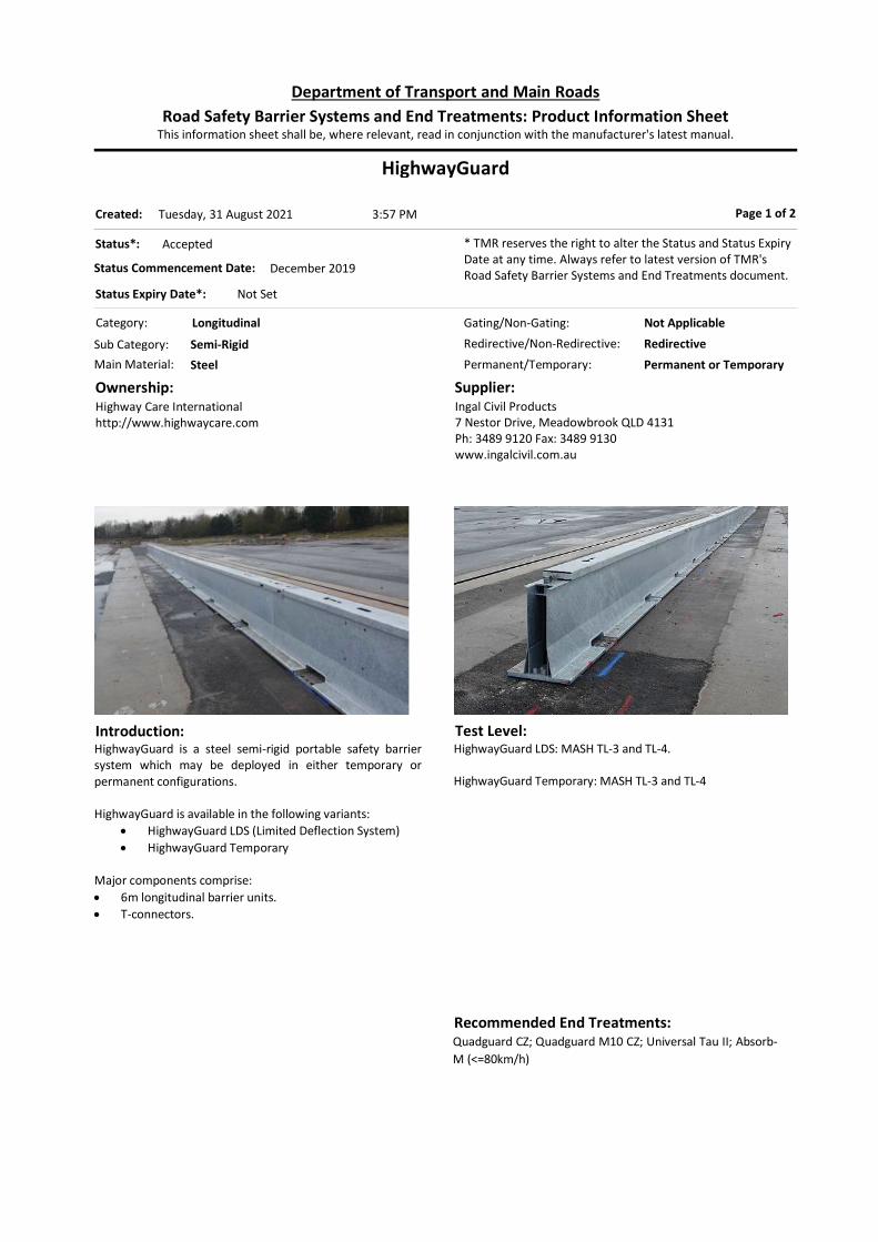
HighwayGuard
Category: Longitudinal
Permanent/Temporary: Permanent or Temporary
Introduction:HighwayGuard is a steel semi-rigid portable safety barrier system which may be deployed in either temporary or permanent configurations. HighwayGuard is available in the following variants:
HighwayGuard LDS (Limited Deflection System) HighwayGuard Temporary
Major components comprise: 6m longitudinal barrier units. T-connectors.
Ownership:Highway Care Internationalhttp://www.highwaycare.com
Supplier:Ingal Civil Products7 Nestor Drive, Meadowbrook QLD 4131Ph: 3489 9120 Fax: 3489 9130www.ingalcivil.com.au
Page 1 of 2
Test Level:HighwayGuard LDS: MASH TL-3 and TL-4. HighwayGuard Temporary: MASH TL-3 and TL-4
Status*: Accepted
Status Commencement Date: December 2019
Status Expiry Date*: Not Set
* TMR reserves the right to alter the Status and Status Expiry Date at any time. Always refer to latest version of TMR's Road Safety Barrier Systems and End Treatments document.
Gating/Non-Gating: Not Applicable
Redirective/Non-Redirective: Redirective
Main Material: Steel
Sub Category: Semi-Rigid
This information sheet shall be, where relevant, read in conjunction with the manufacturer's latest manual.Road Safety Barrier Systems and End Treatments: Product Information Sheet
Department of Transport and Main Roads
3:57 PMTuesday, 31 August 2021Created:
Recommended End Treatments:Quadguard CZ; Quadguard M10 CZ; Universal Tau II; Absorb-M (<=80km/h)

Design: General: HighwayGuard LDS - TL-3 has anchors at 12m spacing which are staggered over the T-Connection. HighwayGuard LDS – TL-4 has anchors at 24m spacing which are staggered over the T-Connection. HighwayGuard Temporary has 6 anchors at the first and last two barrier units each, and 4 anchors every 58m for the remainder. Point of Need: HighwayGuard LDS - TL-3 is considered to be redirective at the interface between barrier and end treatment. HighwayGuard LDS - TL-4 is considered to be redirective at 34.5m from leading end and 49.5m from trailing end, not including terminals. HighwayGuard Temporary - TL-3 is considered to be redirective at the interface between barrier and end treatment. HighwayGuard Temporary - TL-4 is considered to be redirective at 30m from leading or trailing end, not including terminals. Pavement: This system was tested on an asphalt surface. Additional pavement conditions have been permitted by Austroads Safety Barrier Assessment Panel, consult the supplier for full details of permitted foundation pavement conditions. Minimum Length of Barrier:
System MASH Test Level
Minimum Length (m)
Note
HighwayGuard LDS
TL-3 60 1 TL-4 84 1
HighwayGuard Temporary
TL-3 & TL-4 120 1
Notes:
1. Not including terminals.
Limitations: The crossfall between the edge of travelled way and the
barrier should not exceed 8%. Special units may be required for small radius curves.
HighwayGuard Page 2 of 2
References: HighwayGuard LDS Australia & New Zealand Product
Manual (Revision 1.3 - 04/21) HighwayGuard Australia & New Zealand Standard
System Product Manual (Revision 1.4– 03/21) Austroads Acceptance Documents - HighwayGuard LDS
(07-Jun-2021)
Austroads Acceptance Documents - HighwayGuard Temporary (07-Jun-2021)
Horiba Mira Test 3-10, Test 3-11, and Test 3-21 Reports (Mar 2019)
Holmes Solutions TL-4 Test Report (Version 1.2, Aug 2019)
Deflection:Deflection (Normal Design Domain): Measured (Crash Test) Deflections:
Notes: 1. MASH TL-3 test 2. MASH TL-3 test 3. MASH TL-4 test 4. MASH TL-3 test 5. MASH TL-4 test
Operators, designers and supervisors of work zones must be cognisant that deflections outside the point of redirection are typically greater.
Note: 1. MASH TL-3 transition test
Actual clearance distance between barrier and work area/hazard should be determined by risk assessment. Designers are recommended to adopt the largest working width/ deflection value for the nominated containment level.
System Type Nominal Mass (kg)
Nominal Angle (deg)
Nominal Speed (km/h)
Recorded Deflection
(m)
Working Width
(m)
HighwayGuard LDS 1
1100 25 100 0.22 0.63
HighwayGuard LDS 2
2270 25 100 0.68 1.22
HighwayGuard LDS 3
10000 15 90 1.16 2.88
HighwayGuard Temporary 4 1100 25 100 1.41 1.95
HighwayGuard Temporary 4 2270 25 100 1.93 2.47
HighwayGuard Temporary 5 10000 15 90 2.16 3.51
System Type Nominal Mass (kg)
Nominal Angle (deg)
Nominal Speed (km/h)
Recorded Deflection
(m)
Working Width
(m) HighwayGuard LDS to BG800 Transition 1
2270 25 100 0.58 0.98

Defender BarrierTemporary Steel Barrier
Category: Longitudinal
Permanent/Temporary: Temporary
Introduction: Defender Barrier is a steel barrier for temporary use at work zones. Defender Barrier is available in the following variant:
Defender Barrier 70 Defender Barrier 100 LDS Defender Barrier 100 HC Defender Barrier 100 FS
Defender Barrier 70 is a freestanding, concrete ballasted steel barrier. Defender Barrier 100 LDS is a steel barrier that is ground anchored every 9.15 meters. Defender Barrier 100 HC is a steel barrier that is ground anchored every 48.15 meters. Defender Barrier 100 FS is a free standing, concrete ballasted steel barrier with an increased minimum length (than Defender Barrier 70) and an anchored end terminal (s). The system consists of interlocking 3900mm long (effective length) units that are secured in place by a connection pin.
Ownership:Safe Barriers PTE LTDPO Box 148 Novena Post OfficeSingapore913017
Supplier:Safe Barriers Pty. Ltd.PO Box 7178Hemmant, QLD 4174Ph: 1800 169 799www.safebarriers.com
Page 1 of 2
Test Level:Defender Barrier 70 has been tested to MASH test level TL-2. Defender Barrier 100 LDS has been tested to MASH test level TL-3. Defender Barrier 100 HC has been tested to MASH test level TL-4. Defender Barrier 100 FS has been tested to MASH test level TL-3.
Status*: Accepted
Status Commencement Date: Not Set
Status Expiry Date*: Not Set
* TMR reserves the right to alter the Status and Status Expiry Date at any time. Always refer to latest version of TMR's Road Safety Barrier Systems and End Treatments document.
Gating/Non-Gating: Not Applicable
Redirective/Non-Redirective: Redirective
Main Material: Steel
Sub Category: Semi-Rigid
This information sheet shall be, where relevant, read in conjunction with the manufacturer's latest manual.Road Safety Barrier Systems and End Treatments: Product Information Sheet
Department of Transport and Main Roads
3:57 PMTuesday, 31 August 2021Created:
Recommended End Treatments:Absorb 350 for Defender Barrier 70; Absorb-M (<=80km/h) and Quadguard M10 CZ for Defender Barrier 100 LDS and HC systems; Universal TAU-II for Defender Barrier 100 LDS, HC and FS systems. Designer to consult supplier for details of transitions to these terminals.
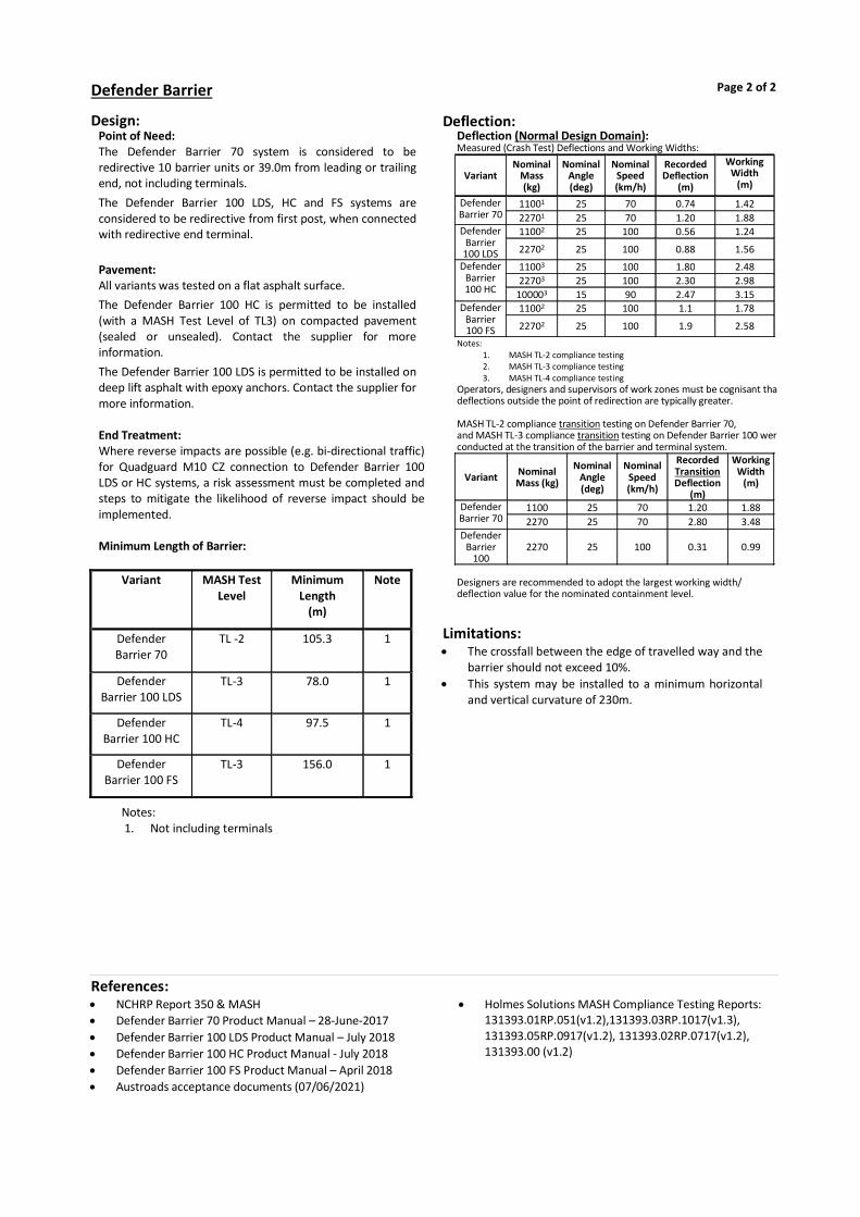
Design:Point of Need: The Defender Barrier 70 system is considered to be redirective 10 barrier units or 39.0m from leading or trailing end, not including terminals.
The Defender Barrier 100 LDS, HC and FS systems are considered to be redirective from first post, when connected with redirective end terminal.
Pavement: All variants was tested on a flat asphalt surface.
The Defender Barrier 100 HC is permitted to be installed (with a MASH Test Level of TL3) on compacted pavement (sealed or unsealed). Contact the supplier for more information.
The Defender Barrier 100 LDS is permitted to be installed on deep lift asphalt with epoxy anchors. Contact the supplier for more information. End Treatment: Where reverse impacts are possible (e.g. bi-directional traffic) for Quadguard M10 CZ connection to Defender Barrier 100 LDS or HC systems, a risk assessment must be completed and steps to mitigate the likelihood of reverse impact should be implemented. Minimum Length of Barrier:
Variant MASH Test Level
Minimum Length
(m)
Note
Defender Barrier 70
TL -2 105.3 1
Defender Barrier 100 LDS
TL-3 78.0 1
Defender Barrier 100 HC
TL-4 97.5 1
Defender Barrier 100 FS
TL-3 156.0 1
Notes: 1. Not including terminals
Limitations: The crossfall between the edge of travelled way and the
barrier should not exceed 10%. This system may be installed to a minimum horizontal
and vertical curvature of 230m.
Defender Barrier Page 2 of 2
References: NCHRP Report 350 & MASH Defender Barrier 70 Product Manual – 28-June-2017 Defender Barrier 100 LDS Product Manual – July 2018 Defender Barrier 100 HC Product Manual - July 2018 Defender Barrier 100 FS Product Manual – April 2018 Austroads acceptance documents (07/06/2021)
Holmes Solutions MASH Compliance Testing Reports: 131393.01RP.051(v1.2),131393.03RP.1017(v1.3), 131393.05RP.0917(v1.2), 131393.02RP.0717(v1.2), 131393.00 (v1.2)
Deflection:Deflection (Normal Design Domain): Measured (Crash Test) Deflections and Working Widths:
Notes: 1. MASH TL-2 compliance testing 2. MASH TL-3 compliance testing 3. MASH TL-4 compliance testing
Operators, designers and supervisors of work zones must be cognisant that deflections outside the point of redirection are typically greater. MASH TL-2 compliance transition testing on Defender Barrier 70, and MASH TL-3 compliance transition testing on Defender Barrier 100 wereconducted at the transition of the barrier and terminal system.
Designers are recommended to adopt the largest working width/ deflection value for the nominated containment level.
Variant Nominal
Mass (kg)
Nominal Angle (deg)
Nominal Speed (km/h)
Recorded Deflection
(m)
Working Width
(m)
Defender Barrier 70
11001 25 70 0.74 1.42 22701 25 70 1.20 1.88
Defender Barrier 100 LDS
11002 25 100 0.56 1.24
22702 25 100 0.88 1.56
Defender Barrier 100 HC
11003 25 100 1.80 2.48 22703 25 100 2.30 2.98
100003 15 90 2.47 3.15 Defender
Barrier 100 FS
11002 25 100 1.1 1.78
22702 25 100 1.9 2.58
Variant Nominal Mass (kg)
Nominal Angle (deg)
Nominal Speed (km/h)
Recorded Transition Deflection
(m)
Working Width
(m)
Defender Barrier 70
1100 25 70 1.20 1.88 2270 25 70 2.80 3.48
Defender Barrier
100 2270 25 100 0.31 0.99
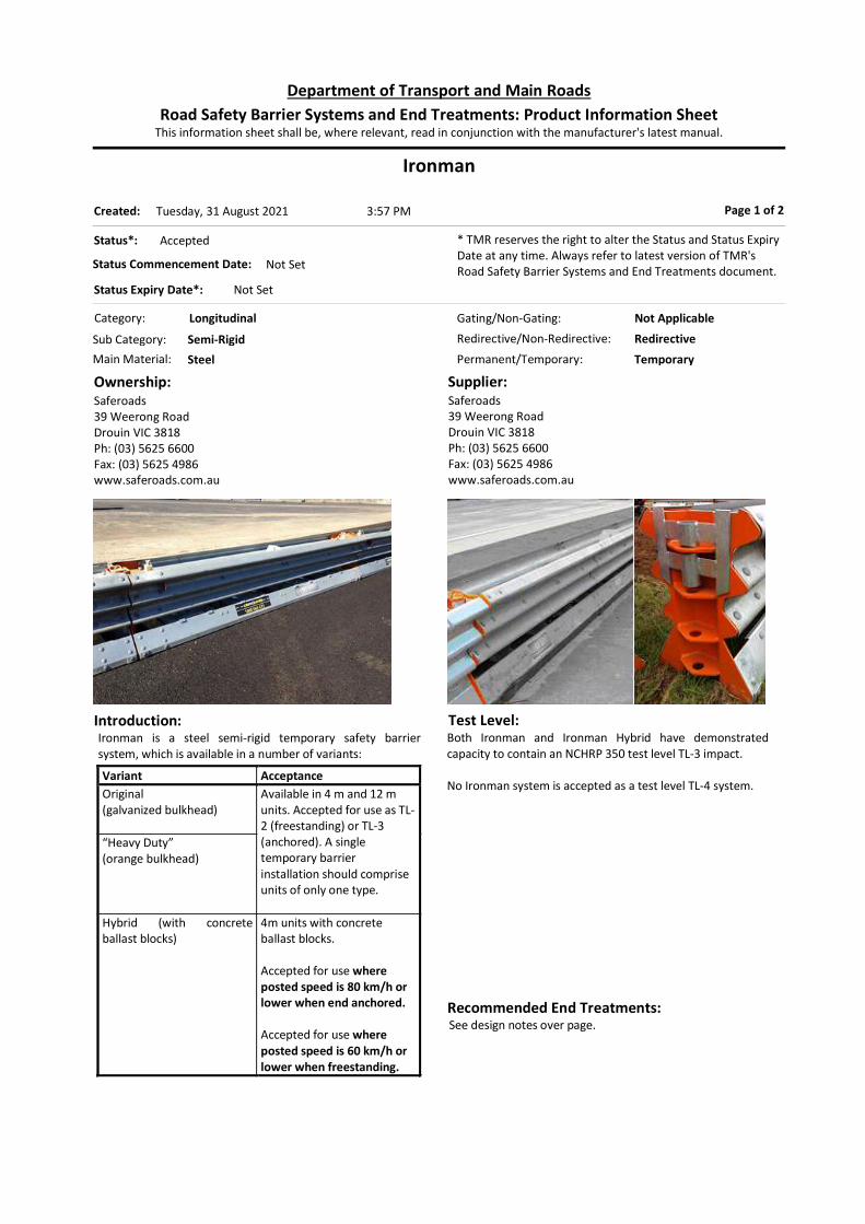
Ironman
Category: Longitudinal
Permanent/Temporary: Temporary
Introduction:Ironman is a steel semi-rigid temporary safety barrier system, which is available in a number of variants:
Variant Acceptance Original (galvanized bulkhead)
Available in 4 m and 12 m units. Accepted for use as TL-2 (freestanding) or TL-3 (anchored). A single temporary barrier installation should comprise units of only one type.
“Heavy Duty” (orange bulkhead)
Hybrid (with concrete ballast blocks)
4m units with concrete ballast blocks. Accepted for use where posted speed is 80 km/h or lower when end anchored. Accepted for use where posted speed is 60 km/h or lower when freestanding.
Ownership:Saferoads39 Weerong RoadDrouin VIC 3818Ph: (03) 5625 6600Fax: (03) 5625 4986www.saferoads.com.au
Supplier:Saferoads39 Weerong RoadDrouin VIC 3818Ph: (03) 5625 6600Fax: (03) 5625 4986www.saferoads.com.au
Page 1 of 2
Test Level:Both Ironman and Ironman Hybrid have demonstrated capacity to contain an NCHRP 350 test level TL-3 impact. No Ironman system is accepted as a test level TL-4 system.
Status*: Accepted
Status Commencement Date: Not Set
Status Expiry Date*: Not Set
* TMR reserves the right to alter the Status and Status Expiry Date at any time. Always refer to latest version of TMR's Road Safety Barrier Systems and End Treatments document.
Gating/Non-Gating: Not Applicable
Redirective/Non-Redirective: Redirective
Main Material: Steel
Sub Category: Semi-Rigid
This information sheet shall be, where relevant, read in conjunction with the manufacturer's latest manual.Road Safety Barrier Systems and End Treatments: Product Information Sheet
Department of Transport and Main Roads
3:57 PMTuesday, 31 August 2021Created:
Recommended End Treatments: See design notes over page.
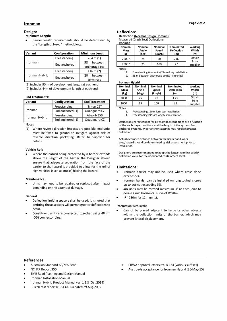
Design:Minimum Length: Barrier length requirements should be determined by
the “Length of Need” methodology. Variant Configuration Minimum Length
Ironman Freestanding 264 m (1)
End anchored 58 m between anchorage pts
Ironman Hybrid Freestanding 116 m (2)
End anchored 20 m between
terminals (1) includes 95 m of development length at each end. (2) includes 44m of development length at each end. End Treatments: Variant Configuration End Treatment
Ironman Freestanding Triton CET End anchored (1) Quadguard CZ
Ironman Hybrid Freestanding Absorb 350 End anchored (1) Quadguard CZ
Notes (1) Where reverse direction impacts are possible, end units
must be fixed to ground to mitigate against risk of reverse direction pocketing. Refer to Supplier for details.
Vehicle Roll: Where the hazard being protected by a barrier extends
above the height of the barrier the Designer should ensure that adequate separation from the face of the barrier to the hazard is provided to allow for the roll of high vehicles (such as trucks) hitting the hazard.
Maintenance: Units may need to be repaired or replaced after impact
depending on the extent of damage. General Deflection limiting spacers shall be used. It is noted that
omitting these spacers will permit greater deflections to occur.
Constituent units are connected together using 48mm (OD) connector pins.
Limitations: Ironman barrier may not be used where cross slope
exceeds 5%. Ironman barrier can be installed on longitudinal slopes
up to but not exceeding 5%. 4m units may be rotated maximum 3° at each joint to
derive a min horizontal curve of R~78m. (R ~230m for 12m units). Interaction with Kerbs Cannot be placed adjacent to kerbs or other objects
within the deflection limits of the barrier, which may prevent lateral displacement.
Ironman Page 2 of 2
References: Australian Standard AS/NZS 3845 NCHRP Report 350 TMR Road Planning and Design Manual Ironman Installation Manual Ironman Hybrid Product Manual ver. 1.1.3 (Oct 2014) E-Tech test report 01-8430-004 dated 29-Aug-2005
FHWA approval letters ref. B-134 (various suffixes) Austroads acceptance for Ironman Hybrid (26-May-15)
Deflection:Deflection (Normal Design Domain): Measured (Crash Test) Deflections: Ironman
Nominal Mass (kg)
Nominal Angle (deg)
Nominal Speed (km/h)
Nominated Deflection
(m)
Working Width
(m)
2000 1 25 70 2.82 Obtain from
supplier 2000 2 25 100 2.1 Notes:
1. Freestanding (4 m units) 224 m long installation 2. 58 m between anchorage points (4 m units)
Ironman Hybrid Nominal
Mass (kg)
Nominal Angle (deg)
Nominal Speed (km/h)
Nominated Deflection
(m)
Working Width
(m)
2000 3 25 70 1.25 Obtain from
supplier 2000 4 25 100 1.9
Notes: 3. Freestanding 120 m long test installation. 4. Freestanding 249.4m long test installation.
Deflection characteristics for given impact conditions are a function of the anchorage conditions and the length of the system. For anchored systems, wider anchor spacings may result in greater deflections. Actual clearance distance between the barrier and work area/hazard should be determined by risk assessment prior to installation. Designers are recommended to adopt the largest working width/ deflection value for the nominated containment level.

SafeZone
Category: Longitudinal
Permanent/Temporary: Permanent or Temporary
Introduction:SafeZone is a semi-rigid steel safety barrier system which can be deployed in a temporary or permanent configuration. Consult supplier for installation requirements for permanent configuration. SafeZone is available in the following variants: SafeZone Standard – requires 4 anchors at the first and
last element, and intermediate anchors at 69.6m spacing.
SafeZone LDS (Limited Deflection System) – requires 2 anchors at the first and last element, and intermediate anchors at 11.6m spacing.
Major components comprise: 5.8m units and 11.6m longitudinal barrier units. Anchorage units including anchor shoe and pin with the
following options (Note that Type A flat top pin is not allowed): - Type B 300mm long threaded rod - Type D 300mm long Excalibur bolt (for SafeZone Standard TL-3 only).
Ownership:Laura Metaal Road Safety Pty Ltdwww.laurametaal.com
Supplier:Australian Construction Products (ACP)339 Horsley Road, Milperra, NSW 2214Ph. 1800 724 172www.acprod.com.au
Page 1 of 2
Test Level:Standard System: MASH TL-3 and TL-4. Limited Deflection System (LDS): MASH TL-3 and TL-4.
Status*: Accepted
Status Commencement Date: December 2019
Status Expiry Date*: Not Set
* TMR reserves the right to alter the Status and Status Expiry Date at any time. Always refer to latest version of TMR's Road Safety Barrier Systems and End Treatments document.
Gating/Non-Gating: Not Applicable
Redirective/Non-Redirective: Redirective
Main Material: Steel
Sub Category: Semi-Rigid
This information sheet shall be, where relevant, read in conjunction with the manufacturer's latest manual.Road Safety Barrier Systems and End Treatments: Product Information Sheet
Department of Transport and Main Roads
3:57 PMTuesday, 31 August 2021Created:
Recommended End Treatments:Universal Tau-II; Universal Tau-M; Absorb-M (<=80km/h) Refer to individual product information sheets for use and limitations.
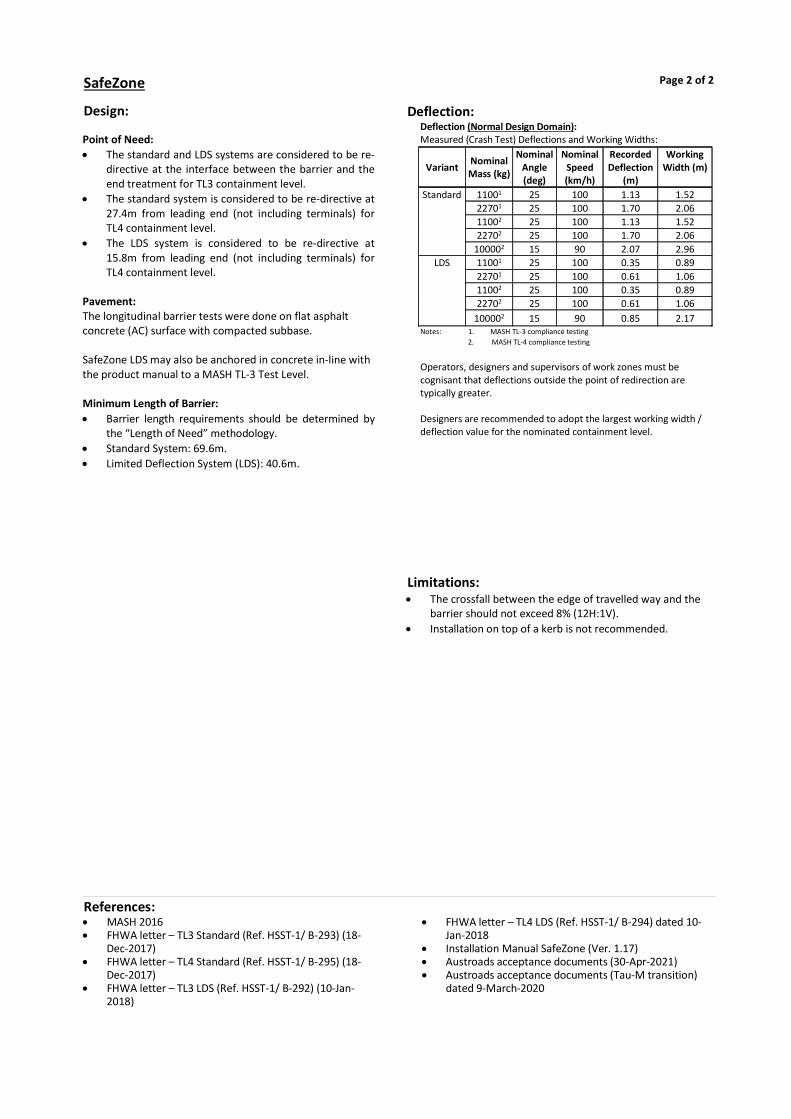
Design: Point of Need: The standard and LDS systems are considered to be re-
directive at the interface between the barrier and the end treatment for TL3 containment level.
The standard system is considered to be re-directive at 27.4m from leading end (not including terminals) for TL4 containment level.
The LDS system is considered to be re-directive at 15.8m from leading end (not including terminals) for TL4 containment level.
Pavement: The longitudinal barrier tests were done on flat asphalt concrete (AC) surface with compacted subbase. SafeZone LDS may also be anchored in concrete in-line with the product manual to a MASH TL-3 Test Level. Minimum Length of Barrier: Barrier length requirements should be determined by
the “Length of Need” methodology. Standard System: 69.6m. Limited Deflection System (LDS): 40.6m.
Limitations: The crossfall between the edge of travelled way and the
barrier should not exceed 8% (12H:1V). Installation on top of a kerb is not recommended.
SafeZone Page 2 of 2
References: MASH 2016 FHWA letter – TL3 Standard (Ref. HSST-1/ B-293) (18-
Dec-2017) FHWA letter – TL4 Standard (Ref. HSST-1/ B-295) (18-
Dec-2017) FHWA letter – TL3 LDS (Ref. HSST-1/ B-292) (10-Jan-
2018)
FHWA letter – TL4 LDS (Ref. HSST-1/ B-294) dated 10-Jan-2018
Installation Manual SafeZone (Ver. 1.17) Austroads acceptance documents (30-Apr-2021) Austroads acceptance documents (Tau-M transition)
dated 9-March-2020
Deflection:Deflection (Normal Design Domain): Measured (Crash Test) Deflections and Working Widths:
Notes: 1. MASH TL-3 compliance testing 2. MASH TL-4 compliance testing
Operators, designers and supervisors of work zones must be cognisant that deflections outside the point of redirection are typically greater. Designers are recommended to adopt the largest working width / deflection value for the nominated containment level.
Variant Nominal Mass (kg)
Nominal Angle (deg)
Nominal Speed (km/h)
Recorded Deflection
(m)
Working Width (m)
Standard 11001 25 100 1.13 1.52 22701 25 100 1.70 2.06 11002 25 100 1.13 1.52 22702 25 100 1.70 2.06
100002 15 90 2.07 2.96 LDS 11001 25 100 0.35 0.89
22701 25 100 0.61 1.06 11002 25 100 0.35 0.89 22702 25 100 0.61 1.06
100002 15 90 0.85 2.17

ZoneguardTemporary Steel Barrier
Category: Longitudinal
Permanent/Temporary: Temporary
Introduction:Zoneguard is Steel Barrier for Temporary use at Work Zones and is required to be anchored to the pavement. Zoneguard is available in two variants: Zoneguard Zoneguard ‘Minimum Deflection System’ Useful Product Data: It comprises of 12m long steel units.
Ownership:Hill and Smith Pty Ltd1/242 New Cleveland Rd Tingalpa. Q 4173PO Box 9406 Wynnum Plaza, Wynnum West. Q 4178Phone 1300 277 683www.hillandsmith.com.au
Supplier:Hill and Smith Pty Ltd1/242 New Cleveland Rd Tingalpa. Q 4173PO Box 9406 Wynnum Plaza, Wynnum West. Q 4178Phone 1300 277 683www.hillandsmith.com.au
Page 1 of 2
Test Level:NCHRP350 TL-4 / MASH TL-3 when anchored with end and intermediate anchors only. MASH TL-3 when fully anchored (i.e., the Minimum Deflection System).
Status*: Accepted
Status Commencement Date: Mar 2013
Status Expiry Date*: Not Set
* TMR reserves the right to alter the Status and Status Expiry Date at any time. Always refer to latest version of TMR's Road Safety Barrier Systems and End Treatments document.
Gating/Non-Gating: Not Applicable
Redirective/Non-Redirective: Redirective
Main Material: Steel
Sub Category: Semi-Rigid
This information sheet shall be, where relevant, read in conjunction with the manufacturer's latest manual.Road Safety Barrier Systems and End Treatments: Product Information Sheet
Department of Transport and Main Roads
3:57 PMTuesday, 31 August 2021Created:
Recommended End Treatments:Absorb 350 (<=70km/hr); Absorb-M (<=80km/hr); Tau II; Quadguard CZ Note that flaring outside the clear-zone and ramped ends are not accepted end treatment solutions.

Design:General Zoneguard has two variants: (i) The standard configuration has end anchors and
intermediate anchors. (ii) The Minimum Deflection System which is continuously
anchored (10.2m spacings). Minimum Length Barrier length requirements should be determined by
the “Length of Need” methodology. Standard System: 75m. Minimum Deflection System: 60m. Anchor Spacings/Deflections The minimum run length of the standard system is 75m,
any extension of barrier above this length will require intermediate anchors every 72m.
The Zoneguard minimum deflection system is anchored every 10.2m.
Designers should consider that, for the same impact, wider anchor spacing will result in greater deflections, and that closer anchor spacing will result in smaller deflections.
Offset from Trafficked Lane: The offset between the barrier and the travelled lane
should be not less than 500 mm. Flare rates shall be as per TMR Road Planning & Design
Manual. Interaction with Kerbs Cannot be placed adjacent to kerbs or other objects
within the deflection limits of the barrier, which may prevent lateral displacement.
Vehicle Roll: Where the hazard being protected by a barrier extends
above the height of the barrier the Designer should ensure that adequate separation from the face of the barrier to the hazard is provided to allow for the roll of high vehicles (such as trucks) hitting the hazard.
Maintenance: Units may need to be repaired or replaced after impact
depending on the extent of damage.
Limitations: The crossfall between the edge of travelled way and the
barrier should not exceed 15H: 1V. Special units may be required for small radius curves. Seek advice from supplier regarding anchorages if
considering installation on concrete surfaces.
Zoneguard Page 2 of 2
References: Australian Standard AS/NZS 3845 NCHRP Report 350 TMR Road Planning and Design Manual NSW RMS Design Report dated 15-Mar-2013 FHWA letter ref. HSSD/B-176A dated 17-Jul-2008 FHWA letter ref. HSSD/B-176 dated 27-Jun-2008
ZoneGuard Specification Manual Metric Australian Version October 2013, Rev 5
Austroads Acceptance Documents (05-Dec-2020)
Deflection:Deflection (Normal Design Domain): Measured (Crash Test) Deflections: Standard Zoneguard (TL-4) 65m between anchors
Nominal Mass (kg)
Nominal Angle (deg)
Nominal Speed (km/h)
Recorded Deflection
(m)
Working Width (m)
20001 25 100 1.65 (Base) Obtain from
Supplier 22702 25 100 1.88 (Base) 80003 15 80 1.27 (Base)
Note: 1 = NCHRP350 3-11; 2 = MASH 3-11; 3 = NCHRP350 4-12 Minimum Deflection System Zoneguard (TL-3) Anchors at 10.2m spacings
Test Mass (kg)
Nominal Angle (deg)
Nominal Speed (km/h)
Recorded Deflection
(m)
Working Width (m)
1065 25 100 0.10 (Base) Obtain from
Supplier
2118 25 100 0.05 (Base)
22084 25 100 0.41 (Top) 0.13 (Base)
Note: 4. Designers should note the base is 271 mm wider horizontally (on
each side) than the top. In this test the maximum intrusion into the work zone was recorded at the top of the barrier rather than the base.
Actual clearance distance between the barrier and work area/hazard should be determined by risk assessment prior to installation. Designers are recommended to adopt the largest working width/ deflection value for the nominated containment level.

HV2Temporary Steel and Concrete Barrier
Category: Longitudinal
Permanent/Temporary: Temporary
Introduction: HV2 Barrier is a freestanding, concrete ballasted steel barrier for temporary use at work zones. The concrete ballast is filled in the bottom one-third of the barrier. The remaining top portion of the barrier is hollow. The barrier system consists of interlocking 5800mm long (effective length) units that are secured in place by proprietary connector. The total weight of each unit including the concrete ballast is 2088 kg or 360 kg per linear metre.
Ownership:Saferoads Pty Ltd22 Commercial Drive, Pakenham, VIC. 3810Ph: 1800 060 072 Fax: 1800 060 673www.saferoads.com.au
Supplier:Saferoads Pty Ltd22 Commercial Drive, Pakenham, VIC. 3810Ph: 1800 060 072 Email: [email protected]
Page 1 of 2
Test Level:MASH test level TL-4
Status*: Accepted
Status Commencement Date: December 2019
Status Expiry Date*: Not Set
* TMR reserves the right to alter the Status and Status Expiry Date at any time. Always refer to latest version of TMR's Road Safety Barrier Systems and End Treatments document.
Gating/Non-Gating: Non-Gating
Redirective/Non-Redirective: Redirective
Main Material: Steel
Sub Category: Semi-Rigid
This information sheet shall be, where relevant, read in conjunction with the manufacturer's latest manual.Road Safety Barrier Systems and End Treatments: Product Information Sheet
Department of Transport and Main Roads
3:57 PMTuesday, 31 August 2021Created:
Recommended End Treatments:Quadguard; SLED (<=80km/h). Note that flaring outside the clear-zone and ramped ends are not accepted end treatment solutions. Designer to consult supplier for details of transitions to this terminal.

Design: Point of Need: The HV2 Barrier system is considered to be re-directive 22.5m from leading and trailing ends (including SLED terminals) for MASH TL-3, and 138.0m from leading and trailing ends (not including terminals) for MASH TL-4. Leading and trailing points of redirection are considered to be 0 for MASH TL-3 only when connected to Quadguard crash cushion. Pavement: The longitudinal barrier test was done on a flat concrete surface, and transition test on a flat asphalt surface. Minimum Length of Barrier: Designer to consult supplier for minimum length of barrier.
Limitations: The crossfall between the edge of travelled way and the
barrier should not exceed 5%. Barriers can be placed on longitudinal slope up to 5%. Barriers cannot be used on radii smaller than 80m. Barriers should not be installed on top of a kerb.
HV2 Page 2 of 2
References: NCHRP Report 350 & MASH 2016 FHWA letter ref. B-308 dated 17-Sep-2018, B-306 dated
17-September-2018 HV2 Barrier Product Manual – Australian Version 1.5
September-2019
Austroads acceptance documents dated 03-October-2019
Deflection:Deflection (Normal Design Domain): Measured (Crash Test) Deflections and Working Widths:
Notes: 1. MASH TL-4 compliance testing
Operators, designers and supervisors of work zones must be cognisant that deflections outside the point of redirection are typically greater. MASH TL-3 compliance transition testing was conducted at the transition of the HV2 barrier and terminal system.
Notes: 1. MASH TL-3 compliance HV2 transition to Quadguard testing 2. MASH TL-3 compliance HV2 transition to SLED testing Designers are recommended to adopt the largest working width/ deflection value for the nominated containment level.
Nominal Mass (kg)
Nominal Angle (deg)
Nominal Speed (km/h)
Recorded Deflection
(m)
Working Width (m)
11001 25 100 0.75 1.05 22701 25 100 1.47 1.81
100001 15 90 2.37 3.74
Nominal Mass (kg)
Nominal Angle (deg)
Nominal Speed (km/h)
Recorded Transition Deflection
(m)
Working Width
(m)
22701 25 100 0.21 1.22 22702 25 100 3.80 4.37
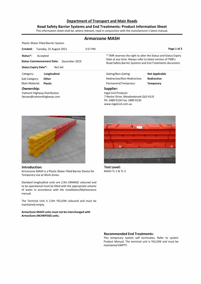
Armorzone MASHPlastic Water Filled Barrier System
Category: Longitudinal
Permanent/Temporary: Temporary
Introduction:Armorzone MASH is a Plastic Water Filled Barrier Device for Temporary Use at Work Zones. Standard longitudinal units are 2.0m ORANGE coloured and to be operational must be filled with the appropriate volume of water in accordance with the Installation/Maintenance manual. The Terminal Unit is 2.0m YELLOW coloured and must be maintained empty. ArmorZone MASH units must not be interchanged with ArmorZone (NCHRP350) units.
Ownership:Valmont Highway [email protected]
Supplier:Ingal Civil Products7 Nestor Drive, Meadowbrook QLD 4131Ph: 3489 9120 Fax: 3489 9130www.ingalcivil.com.au
Page 1 of 2
Test Level:MASH TL-1 & TL-2
Status*: Accepted
Status Commencement Date: December 2019
Status Expiry Date*: Not Set
* TMR reserves the right to alter the Status and Status Expiry Date at any time. Always refer to latest version of TMR's Road Safety Barrier Systems and End Treatments document.
Gating/Non-Gating: Not Applicable
Redirective/Non-Redirective: Redirective
Main Material: Plastic
Sub Category: Other
This information sheet shall be, where relevant, read in conjunction with the manufacturer's latest manual.Road Safety Barrier Systems and End Treatments: Product Information Sheet
Department of Transport and Main Roads
3:57 PMTuesday, 31 August 2021Created:
Recommended End Treatments:This temporary system self terminates. Refer to system Product Manual. The terminal unit is YELLOW and must be maintained EMPTY.

Design: The system is considered to be redirective 24m past the leading unit and 26m before the trailing unit. Minimum Length of Barrier:
MASH Test Level Minimum Length (m)
TL-1 50.0*
TL-2 50.0*
*Not including terminals
Limitations:Information has not been entered.
Armorzone MASH Page 2 of 2
References: Australian Standard AS/NZS 3845 MASH 2016 TMR Road Planning and Design Manual ArmorZone MASH TL-2 Temporary Safety Barrier
Product Manual (Release 03/19) Austroads acceptance documents (05-Sep-2019)
Holmes Solutions Test 1-11 Report (18-Oct-2019)
Deflection:Deflection (Normal Design Domain): Measured (Crash Test) Deflections:
Nominal Mass (kg)
Nominal Angle (deg)
Nominal Speed (km/h)
Recorded Deflection
(m)
Recorded Working
Width (m)
2,2701 25 50 2.16 2.61
1,1002 25 70 2.02 2.47
2,2702 25 70 4.1 4.6
1. MASH TL-1 Test 2. MASH TL-2 Test Actual clearance distance between the barrier and work area/hazard should be determined by risk assessment prior to installation. These deflections in the table above are not applicable in the vicinity of terminals. Designers are recommended to adopt the largest working width/ deflection value for the nominated containment level.
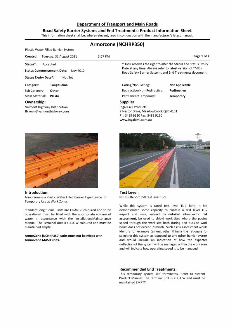
Armorzone (NCHRP350)Plastic Water Filled Barrier System
Category: Longitudinal
Permanent/Temporary: Temporary
Introduction:Armorzone is a Plastic Water Filled Barrier Type Device for Temporary Use at Work Zones. Standard longitudinal units are ORANGE coloured and to be operational must be filled with the appropriate volume of water in accordance with the Installation/Maintenance manual. The Terminal Unit is YELLOW coloured and must be maintained empty. ArmorZone (NCHRP350) units must not be mixed with ArmorZone MASH units.
Ownership:Valmont Highway [email protected]
Supplier:Ingal Civil Products7 Nestor Drive, Meadowbrook QLD 4131Ph: 3489 9120 Fax: 3489 9130www.ingalcivil.com.au
Page 1 of 2
Test Level:NCHRP Report 350 test level TL-1. While this system is rated test level TL-1 here, it hasdemonstrated some capacity to contain a test level TL-2impact and may, subject to detailed site-specific riskassessment, be used to shield work-sites where the postedspeed through the work-site both during and outside workhours does not exceed 70 km/h. Such a risk assessment would identify for example (among other things) the rationale for selecting this system as opposed to any other barrier system and would include an indication of how the expected deflection of the system will be managed within the work zone and will indicate how operating speed is to be managed.
Status*: Accepted
Status Commencement Date: Nov 2012
Status Expiry Date*: Not Set
* TMR reserves the right to alter the Status and Status Expiry Date at any time. Always refer to latest version of TMR's Road Safety Barrier Systems and End Treatments document.
Gating/Non-Gating: Not Applicable
Redirective/Non-Redirective: Redirective
Main Material: Plastic
Sub Category: Other
This information sheet shall be, where relevant, read in conjunction with the manufacturer's latest manual.Road Safety Barrier Systems and End Treatments: Product Information Sheet
Department of Transport and Main Roads
3:57 PMTuesday, 31 August 2021Created:
Recommended End Treatments:This temporary system self terminates. Refer to system Product Manual. The terminal unit is YELLOW and must be maintained EMPTY.

Design:End Treatments: This system has an end treatment that has been
successfully crash tested. Under TL-1 impact conditions, the system is considered
to be redirective from a point 16m from the head of the system.
Minimum Length: 52m between terminals, 56m total. Designers of work zones should refer to the suppliers’
installation manual for further guidance on hazard free zones and deflection.
Deflection:
For TL-1 impacts:
When measured from the head of the system, the first 16m is considered to be gating/non-redirective.
Between 16m an d 28m (measured from both the upstream and the downstream end) the expected deflectio n distance is 2.4m.
Downstream of 28m (up to a point 28m from the downstream end), the exp ected deflection distance is
1.51m. For a minimum length installation (56m) the system is
“redirective” between 16m and 40m from the end, and the expected deflection distance for a TL-1 impact in this zone is taken as 2.4m.
Limitations:Information has not been entered.
Armorzone (NCHRP350) Page 2 of 2
References: Australian Standard AS/NZS 3845 NCHRP Report 350 TMR Road Planning and Design Manual FHWA letter ref. HSST/B-223 dated 22 Aug 2011 Armorzone Plastic Barrier Product Manual (ref 300812)
Armorzone End Treatment Product Manual (ref 300812)
NSW Transport RMS Safety Barrier Design Report 11M965 (29-Aug-2012)
Deflection:Deflection (Normal Design Domain): Measured (Crash Test) Deflections: Nominal
Mass (kg)
Nominal Angle (deg)
Nominal Speed (km/h)
Recorded Deflection
(m)
Working Width
(m) 820 20 70 1.05 Obtain
from supplier 1500 20 70 1.51
Actual clearance distance between the barrier and work area/hazard should be determined by risk assessment prior to installation. Designers are recommended to adopt the largest working width / deflection value for the nominated containment level.

RicochetPlastic Water Filled Barrier System
Category: Longitudinal
Permanent/Temporary: Temporary
Introduction:Ricochet is a Plastic Water Filled Barrier Type Device for Temporary Use at Work Zones. The barrier system consists of a series of interlocking 2m plastic barrier units. Standard longitudinal units are orange coloured. Orange units must be filled with the appropriate volume of water in accordance with the Installation/Maintenance manual. The terminal consists of two 2m yellow coloured units plus a 0.55m yellow end cap, and ALL yellow coloured units must be maintained empty.
Ownership:Advantage Plastics254 Easterbrook Road, RD1 Kaiapoi 7691, NZPh: 0800 668 534 Mob: 021 228 5284www.advantageplastics.co.nz
Supplier:TFH Hire8-14 Eurora Street, Kingston, QLD 4114www.tfh.com.au
Page 1 of 2
Test Level:MASH TL-1
Status*: Accepted
Status Commencement Date: April 2019
Status Expiry Date*: Not Set
* TMR reserves the right to alter the Status and Status Expiry Date at any time. Always refer to latest version of TMR's Road Safety Barrier Systems and End Treatments document.
Gating/Non-Gating: Non-Gating
Redirective/Non-Redirective: Redirective
Main Material: Plastic
Sub Category: Other
This information sheet shall be, where relevant, read in conjunction with the manufacturer's latest manual.Road Safety Barrier Systems and End Treatments: Product Information Sheet
Department of Transport and Main Roads
3:57 PMTuesday, 31 August 2021Created:
Recommended End Treatments:This temporary system self terminates. Refer to system Product Manual. The terminal units are YELLOW are NOT filled with water.

Design: The system is considered to be redirective 20m past the leading unit and 20m before the trailing unit. Minimum Length of Barrier:
MASH Test Level Minimum Length (m)
TL -1 40.0*
*Not including terminals
Limitations:Information has not been entered.
Ricochet Page 2 of 2
References: Australian Standard AS/NZS 3845 MASH 2016 TMR Road Planning and Design Manual Ricochet Waterfilled Barrier System – MASH
(06/03/2019) Holmes Solutions report ref.131677.00(v1.1)
Holmes Solutions Report. Ref 102350.15-1-1A (v1.2)
Deflection:Deflection (Normal Design Domain): Measured (Crash Test) Deflections:
Nominal Mass (kg)
Nominal Angle (deg)
Nominal Speed (km/h)
Recorded Deflection
(m)
Recorded Working
Width (m)
1,1001 25 70 2.50 3.08
2,2702 25 50 2.28 2.86
1. This is a small car MASH TL-2 test instead of a MASH TL-1. Recorded Deflection and Working Width are not applicable to TL-1 impacts.
2. MASH TL-1 Test Actual clearance distance between the barrier and work area/hazard should be determined by risk assessment prior to installation. These deflections in the table above are not applicable in the vicinity of terminals. Designers are recommended to adopt the largest working width/ deflection value for the nominated containment level.

Lo-Ro Water Cable BarrierPlastic Water Filled Barrier System
Category: Longitudinal
Permanent/Temporary: Temporary
Introduction:Lo-Ro Water Cable Barrier is a Plastic Water Filled Barrier Device for Temporary Use at Work Zones. Standard longitudinal units are 1.92m ORANGE and WHITE coloured and to be operational must be filled with the appropriate volume of water in accordance with the Installation/Maintenance manual. The Terminal Unit is 2.25m (including Containment Impact Sled) YELLOW coloured SLED Lo-Ro Terminal which is a gating terminal and filled with water.
Ownership:TrafFix Devices Inc.160 Avenida La PataSan Clemente, California 92673www.traffixdevices.com
Supplier:Jaybro Group Pty Ltd29 Penelope Crescent, Arndell Park, NSW 2148Ph: 1300 885 [email protected]
Page 1 of 2
Test Level:MASH TL-1 and TL-2
Status*: Accepted
Status Commencement Date: December 2019
Status Expiry Date*: Not Set
* TMR reserves the right to alter the Status and Status Expiry Date at any time. Always refer to latest version of TMR's Road Safety Barrier Systems and End Treatments document.
Gating/Non-Gating: Not Applicable
Redirective/Non-Redirective: Redirective
Main Material: Plastic
Sub Category: Other
This information sheet shall be, where relevant, read in conjunction with the manufacturer's latest manual.Road Safety Barrier Systems and End Treatments: Product Information Sheet
Department of Transport and Main Roads
3:57 PMTuesday, 31 August 2021Created:
Recommended End Treatments:This temporary system must use SLED Lo-Ro Terminal. Refer to system Product Manual.

Design: The system is considered to be redirective 24m past the leading unit and 24m before the trailing unit. Minimum Length of Barrier:
MASH Test Level Minimum Length (m)
TL-1 48.0*
TL-2 48.0*
*Not including terminals
Limitations:Information has not been entered.
Lo-Ro Water Cable Barrier Page 2 of 2
References: Australian Standard AS/NZS 3845 MASH 2016 TMR Road Planning and Design Manual Lo-Ro Water Cable Barrier Installation Procedure
Manual (Revision A3, 30-Dec-2019) Austroads acceptance documents (02-Jun-2020)
Applus IDIADA KARCO Lo-Ro TL-2 Test Reports (22-Mar-2019, and 01-Feb-2019)
Applus IDIADA KARCO SLED Lo-Ro Test Reports (31-Jul-2019, 23-Jul-2019, and 02-Aug-2019)
Applus IDIADA KARCO Lo-Ro Test 1-11 Report (11-Oct-2019)
Deflection:Deflection (Normal Design Domain): Measured (Crash Test) Deflections:
Nominal Mass (kg)
Nominal Angle (deg)
Nominal Speed (km/h)
Recorded Deflection
(m)
Recorded Working
Width (m)
2,2701 25 50 1.8 2.3
1,1002 25 70 2.1 2.5
2,2702 25 70 3.6 4.1
Notes: 1. MASH TL-1 test without terminals 2. MASH TL-2 test without terminals MASH TL-2 compliance terminal testing was conducted with SLED Lo-Ro Terminal. Results from compliance testing for terminal:
Nominal Mass (kg)
Nominal Angle (deg)
Nominal Speed (km/h)
Recorded Deflection
(m)
Recorded Working
Width (m)
1,1001 0 70 1.3 1.5
2,2701 0 70 3.2 0.9
1,1001 5 70 1.6 0.1
2,2701 5 70 6 1.6
2,2701 20 70 13 9.8
Note: 1. MASH TL-2 test with SLED Lo-Ro Terminal Actual clearance distance between the barrier and work area/hazard should be determined by risk assessment prior to installation. Designers are recommended to adopt the largest working width / deflection value for the nominated containment level.
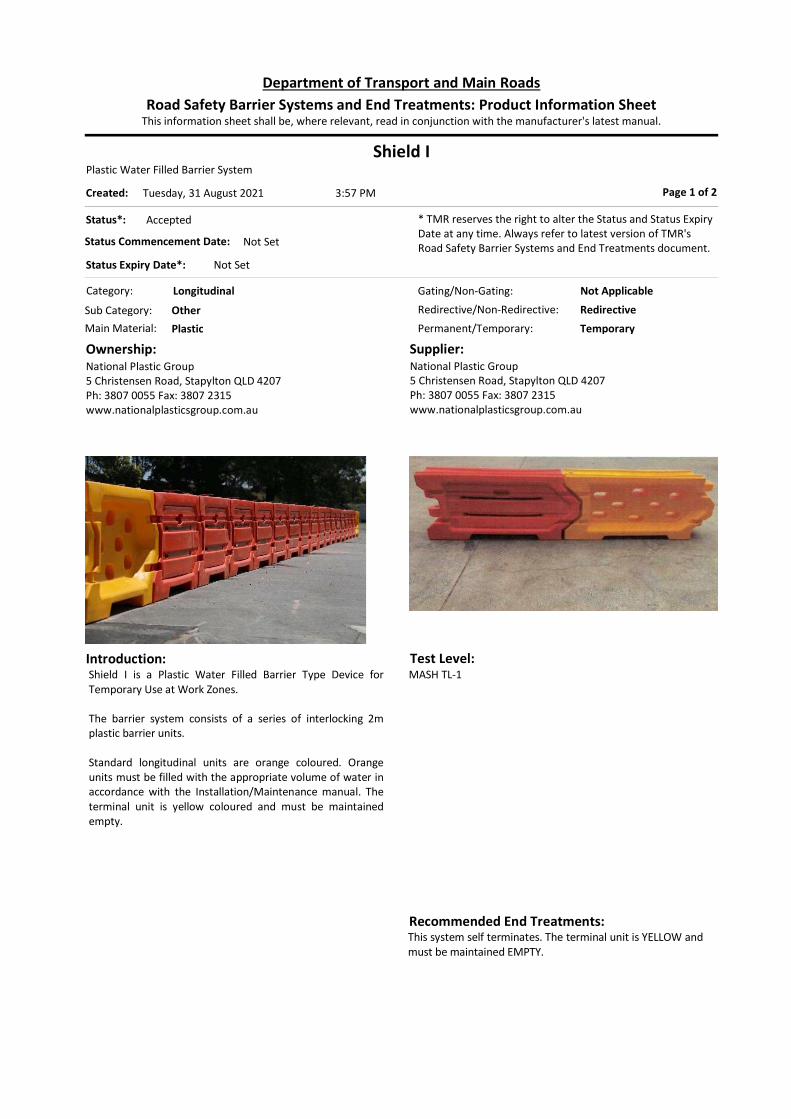
Shield IPlastic Water Filled Barrier System
Category: Longitudinal
Permanent/Temporary: Temporary
Introduction:Shield I is a Plastic Water Filled Barrier Type Device for Temporary Use at Work Zones. The barrier system consists of a series of interlocking 2m plastic barrier units. Standard longitudinal units are orange coloured. Orange units must be filled with the appropriate volume of water in accordance with the Installation/Maintenance manual. The terminal unit is yellow coloured and must be maintained empty.
Ownership:National Plastic Group5 Christensen Road, Stapylton QLD 4207Ph: 3807 0055 Fax: 3807 2315www.nationalplasticsgroup.com.au
Supplier:National Plastic Group5 Christensen Road, Stapylton QLD 4207Ph: 3807 0055 Fax: 3807 2315www.nationalplasticsgroup.com.au
Page 1 of 2
Test Level:MASH TL-1
Status*: Accepted
Status Commencement Date: Not Set
Status Expiry Date*: Not Set
* TMR reserves the right to alter the Status and Status Expiry Date at any time. Always refer to latest version of TMR's Road Safety Barrier Systems and End Treatments document.
Gating/Non-Gating: Not Applicable
Redirective/Non-Redirective: Redirective
Main Material: Plastic
Sub Category: Other
This information sheet shall be, where relevant, read in conjunction with the manufacturer's latest manual.Road Safety Barrier Systems and End Treatments: Product Information Sheet
Department of Transport and Main Roads
3:57 PMTuesday, 31 August 2021Created:
Recommended End Treatments:This system self terminates. The terminal unit is YELLOW and must be maintained EMPTY.
Design: The system is considered to be redirective past 13 leading orange units and before 9 trailing orange units. End Treatments: This system self terminates and has been successfully crash tested. Minimum Length of Barrier:
MASH Test Level Minimum Length (m)
Note
TL -1 44 1
Notes: 1. Not including terminals
Limitations:Information has not been entered.
Shield I Page 2 of 2
References: Australian Standard AS/NZS 3845 MASH 2009 TMR Road Planning and Design Manual Shield I Plastic Barrier Product Manual Holmes Solutions report ref.110971.01RP.0217(v1.2)
Deflection:Deflection (Normal Design Domain): Measured (Crash Test) Deflections:
Nominal Mass (kg)
Nominal Angle (deg)
Nominal Speed (km/h)
Recorded Deflection
(m)
Working Width
(m)
1,1001 25 50 1.37 1.37
2,2701 25 50 2.19 2.19
Notes: 1. MASH TL-1 compliance testing on Shield I system. Actual clearance distance between the barrier and work area/hazard should be determined by risk assessment prior to installation. These deflections in the table above are not applicable in the vicinity of terminals. Designers are recommended to adopt the largest working width/ deflection value for the nominated containment level.

TritonPlastic Water Filled Barrier System
Category: Longitudinal
Permanent/Temporary: Temporary
Introduction:The Triton barrier is a portable water-filled temporary barrier system, with an internal steel frame. Useful Product Data: Physical Length 2130mm Effective Length 2000mm Width 530mm Height 810mm Mass empty 65kg Mass (full of water) 610kg Note: The Triton TL-3 variant (i.e. mounted on pedestals) is no
longer supported by TMR as a longitudinal barrier system.
The Triton TL-0 variant (i.e. without the internal steel frame) is no longer accepted by TMR for use as a road safety barrier on state-controlled roads in Queensland.
Ownership:Energy Absorption SystemsChicago, Illinoiswww.energyabsorption.com
Supplier:Ingal Civil Products7 Nestor Drive, Meadowbrook QLD 4131Ph: 3489 9120 Fax: 3489 9130www.ingalcivil.com.au
Page 1 of 2
Test Level:NCHRP Report 350 test level TL-1. While this system is rated test level TL-1 here, it has demonstrated some capacity to contain a test level TL-2 impact and may, subject to detailed site-specific risk assessment, be used to shield work-sites where the posted speed through the work-site both during and outside work hours does not exceed 70 km/h. Such a risk assessment would identify for example (among other things) the rationale for selecting this system as opposed to any other barrier system and would include an indication of how the expected deflection of the system will be managed within the work zone and will indicate how operating speed is to be managed.
Status*: Accepted
Status Commencement Date: Not Set
Status Expiry Date*: Not Set
* TMR reserves the right to alter the Status and Status Expiry Date at any time. Always refer to latest version of TMR's Road Safety Barrier Systems and End Treatments document.
Gating/Non-Gating: Not Applicable
Redirective/Non-Redirective: Redirective
Main Material: Plastic
Sub Category: Other
This information sheet shall be, where relevant, read in conjunction with the manufacturer's latest manual.Road Safety Barrier Systems and End Treatments: Product Information Sheet
Department of Transport and Main Roads
3:57 PMTuesday, 31 August 2021Created:
Recommended End Treatments:Refer to ‘Design’ in this data sheet and the manufacturers’ manual for terminal configuration. Note: Triton CET (Concrete End Terminal) is not a suitable end treatment for the Triton longitudinal barrier system.
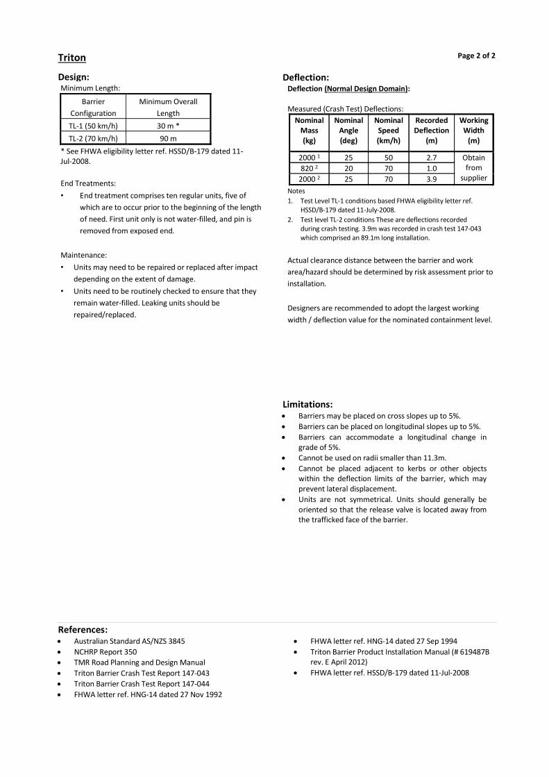
Design:Minimum Length:
Barrier Configuration
Minimum Overall Length
TL-1 (50 km/h) 30 m * TL-2 (70 km/h) 90 m
* See FHWA eligibility letter ref. HSSD/B-179 dated 11-Jul-2008. End Treatments: • End treatment comprises ten regular units, five of
which are to occur prior to the beginning of the length of need. First unit only is not water-filled, and pin is removed from exposed end.
Maintenance: • Units may need to be repaired or replaced after impact
depending on the extent of damage. • Units need to be routinely checked to ensure that they
remain water-filled. Leaking units should be repaired/replaced.
Limitations: Barriers may be placed on cross slopes up to 5%. Barriers can be placed on longitudinal slopes up to 5%. Barriers can accommodate a longitudinal change in
grade of 5%. Cannot be used on radii smaller than 11.3m. Cannot be placed adjacent to kerbs or other objects
within the deflection limits of the barrier, which may prevent lateral displacement.
Units are not symmetrical. Units should generally be oriented so that the release valve is located away from the trafficked face of the barrier.
Triton Page 2 of 2
References: Australian Standard AS/NZS 3845 NCHRP Report 350 TMR Road Planning and Design Manual Triton Barrier Crash Test Report 147-043 Triton Barrier Crash Test Report 147-044 FHWA letter ref. HNG-14 dated 27 Nov 1992
FHWA letter ref. HNG-14 dated 27 Sep 1994 Triton Barrier Product Installation Manual (# 619487B
rev. E April 2012) FHWA letter ref. HSSD/B-179 dated 11-Jul-2008
Deflection:Deflection (Normal Design Domain): Measured (Crash Test) Deflections:
Nominal Mass (kg)
Nominal Angle (deg)
Nominal Speed (km/h)
Recorded Deflection
(m)
Working Width
(m)
2000 1 25 50 2.7 Obtain from
supplier 820 2 20 70 1.0
2000 2 25 70 3.9 Notes 1. Test Level TL-1 conditions based FHWA eligibility letter ref.
HSSD/B-179 dated 11-July-2008. 2. Test level TL-2 conditions These are deflections recorded
during crash testing. 3.9m was recorded in crash test 147-043 which comprised an 89.1m long installation.
Actual clearance distance between the barrier and work area/hazard should be determined by risk assessment prior to installation. Designers are recommended to adopt the largest working width / deflection value for the nominated containment level.

Mobile Barriers MBT-1
Category: Other
Permanent/Temporary: Temporary
Introduction:The Mobile Barriers MBT-1 is a mobile barrier system that provides a mobile work zone for personnel at applicable maintenance and construction sites. The system includes the following: - The Mobile Barriers MBT-1 trailer - A suitable tractor unit - A speed appropriate TMA
Ownership:Mobile Barriers LLC24918 Genesee Trail RoadGolden, Colorado 80401USA
Supplier:Mobile Barriers LLC24918 Genesee Trail RoadGolden, Colorado 80401USAPh 0432 931 981
Page 1 of 2
Test Level:Mobile Barriers MBT-1 has been tested to: MASH TL-3
Status*: Accepted
Status Commencement Date: Not Set
Status Expiry Date*: Not Set
* TMR reserves the right to alter the Status and Status Expiry Date at any time. Always refer to latest version of TMR's Road Safety Barrier Systems and End Treatments document.
Gating/Non-Gating: Not Applicable
Redirective/Non-Redirective: Redirective
Main Material: Other
Sub Category: Other
This information sheet shall be, where relevant, read in conjunction with the manufacturer's latest manual.Road Safety Barrier Systems and End Treatments: Product Information Sheet
Department of Transport and Main Roads
3:57 PMTuesday, 31 August 2021Created:
Recommended End Treatments:Rear of the Mobile Barriers MBT-1 must be fitted with a speed appropriate TMA.

Design:The Mobile Barriers MBT-1 is a mobile temporary work zone barrier. Length and Dimensions Subject to registration and permit requirements the system can be assembled in three configurations
- two platforms and one wall section, or - two platforms and two wall sections, or - two platforms and three wall sections.
Each wall section is 6.1 m long. Length with two platforms and three wall sections (not including tractor or TMA) is 31m. Road clearance is 300mm. Ballast The Mobile Barriers MBT-1 was ballasted in the crash test, and thus operators, designers and supervisors of work zones must be cognisant of the ballast when in use to protect a work zone. The supplier should be consulted on the expected system performance for configurations different to the crash tested configuration. Truck Mounted Attenuator Selection of a suitable TMA for the Mobile Barriers MBT-1 should undergo a separate acceptance process. The rated test level of the attached TMA will assist in defining the acceptable operating conditions, e.g. speed environment. Configuration The Mobile Barriers MBT-1 configuration (e.g. number of assembled wall sections) may affect the operation of the device, such as:
- Available work zone area - Vehicle swept path and crest or sag traversability - Mass of the system in comparison to crash test
Site Conditions Surface type and geometry may affect the performance of the system.
Limitations:1. The use of Mobile Barriers MBT-1 on the Queensland
state-controlled road network is subject to fulfillment of legislated requirements to be registered as a vehicle and any other permit requirements pursuant to such registration.
2. This document does not connote any acceptance of the Mobile Barriers MBT-1 to operate as a Truck Mounted Attenuator.
3. This document does not connote any acceptance for use of the device in accordance with the Queensland MUTCD requirements.
Mobile Barriers MBT-1 Page 2 of 2
References: AS/NZS 3845 MASH (AASHTO, 2009) Austroads conditions document (17-Feb-2015) FHWA eligibility letter ref. HSSD/B-178 (5-Jun-2008) SwRI Test No. MBT-1 (Apr-2008)
Deflection:Deflection (Normal Design Domain): Measured (Crash Test) Deflections:
Nominal Mass (kg)
Nominal Angle (deg)
Nominal Speed (km/h)
Recorded Deflection
(m)
Working Width
(m)
2,270 1 25 100 0.61 Obtain from
supplier
Notes: 1. SwRI Test No. MBT-1 (April 2008). Test was on longest
configuration (two platforms and three wall sections) of the system, fully ballasted with the system stationary on a concrete surface including a tractor but not with a TMA. The mass of the tested article was 29.5 tonnes.
2. Actual clearance distance between barrier and work zone should be determined by risk assessment.
Designers are recommended to adopt the largest working width / deflection value for the nominated containment level.

Absorb 350
Category: End Treatment
Permanent/Temporary: Temporary
Introduction:Absorb 350 is a water filled non-redirective, gating LDPE/Steel crash attenuator that attaches to temporary concrete barriers. Useful Product Data Unit Length - 1m Unit Width - 0.61m Unit Height - 0.8m Unit Weight - 39kg empty, 326kg full.
Ownership:Barrier Systems3333 Vaca Valley Pkwy, Ste. 800, Vacaville, CA 95688, USA www.barriersystemsinc.com
Supplier:Australian Construction Products (ACP)339 Horsley Road, Milperra, NSW 2214Ph. 1800 724 172www.acprod.com.au
Page 1 of 2
Test Level:Restricted to use at work zones that are posted <=70km/h both during and outside work hours, with placement in higher speed zones subject to site specific risk assessment noting that the system may be used only where high speed side impacts are unlikely, penetration behind the barrier is acceptable and use of a redirecting impact attenuator (a crash cushion) is not feasible for reasons other than cost or convenience. Such a risk assessment would identify for example (among other things) the rationale for selecting this system as opposed to any other system and would include an indication of how operating speed is to be managed. Note that configuration varies when intended for use in higher speed zones.
Status*: Accepted
Status Commencement Date: Not Set
Status Expiry Date*: Not Set
* TMR reserves the right to alter the Status and Status Expiry Date at any time. Always refer to latest version of TMR's Road Safety Barrier Systems and End Treatments document.
Gating/Non-Gating: Gating
Redirective/Non-Redirective: Non-Redirective
Main Material: Plastic
Sub Category: Attenuator
This information sheet shall be, where relevant, read in conjunction with the manufacturer's latest manual.Road Safety Barrier Systems and End Treatments: Product Information Sheet
Department of Transport and Main Roads
3:57 PMTuesday, 31 August 2021Created:
Recommended End Treatments:Not Applicable.

Design: Design shall be in accordance with the Absorb 350
Installation and Maintenance Manual. As the system is gating, a run-out area in accordance
with the requirements of AS/NZS 3845 Figure F11 should be provided.
A proprietary transition from the Absorb 350 to a concrete barrier is required.
Offset from Trafficked Lane: The offset between the barrier and the travelled lane
should be not less than 500 mm (RPDM 8.3.4.4). Installation and Maintenance Requirements: The product shall be installed and repaired after impact
in accordance with the Absorb 350. Installation and Maintenance Manual by Barrier Systems Inc.
TL-2 compliant system is 5.9m (5 units) long. Designers are strongly encouraged to read the FHWA letters referred below.
Limitations: As the system is non-redirective, a vehicle may
penetrate the system. A run-out area in accordance with the requirements of AS3845 Figure F11 shall be provided.
System shall not be used in a permanent application. All kerbs, islands and elevated objects greater than
100mm high that would be beneath, beside or less than 15m in front of the unit or along the length of the unit should be removed.
Absorb 350 Page 2 of 2
References: Australian Standard AS/NZS 3845 NCHRP Report 350 TMR Road Planning and Design Manual Absorb 350 Crash Cushion ACP Installation Manual FHWA letters ref. HSA-CC66, HSA-CC66A and HSA-10/CC66B
Deflection:Information has not been entered.
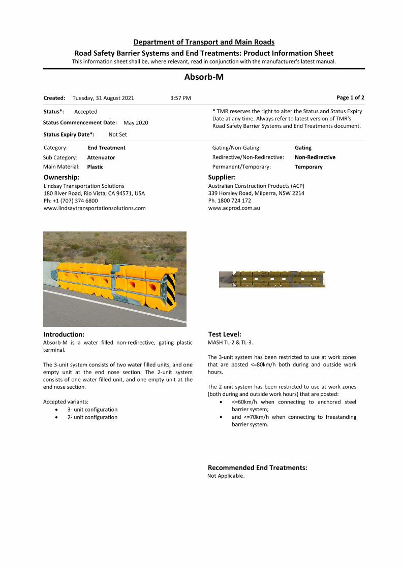
Absorb-M
Category: End Treatment
Permanent/Temporary: Temporary
Introduction:Absorb-M is a water filled non-redirective, gating plastic terminal. The 3-unit system consists of two water filled units, and one empty unit at the end nose section. The 2-unit system consists of one water filled unit, and one empty unit at the end nose section. Accepted variants:
3- unit configuration 2- unit configuration
Ownership:Lindsay Transportation Solutions 180 River Road, Rio Vista, CA 94571, USAPh: +1 (707) 374 6800www.lindsaytransportationsolutions.com
Supplier:Australian Construction Products (ACP)339 Horsley Road, Milperra, NSW 2214Ph. 1800 724 172www.acprod.com.au
Page 1 of 2
Test Level:MASH TL-2 & TL-3. The 3-unit system has been restricted to use at work zones that are posted <=80km/h both during and outside work hours. The 2-unit system has been restricted to use at work zones (both during and outside work hours) that are posted:
<=60km/h when connecting to anchored steel barrier system;
and <=70km/h when connecting to freestanding barrier system.
Status*: Accepted
Status Commencement Date: May 2020
Status Expiry Date*: Not Set
* TMR reserves the right to alter the Status and Status Expiry Date at any time. Always refer to latest version of TMR's Road Safety Barrier Systems and End Treatments document.
Gating/Non-Gating: Gating
Redirective/Non-Redirective: Non-Redirective
Main Material: Plastic
Sub Category: Attenuator
This information sheet shall be, where relevant, read in conjunction with the manufacturer's latest manual.Road Safety Barrier Systems and End Treatments: Product Information Sheet
Department of Transport and Main Roads
3:57 PMTuesday, 31 August 2021Created:
Recommended End Treatments:Not Applicable.

Design:The Absorb-M must be installed and maintained in accordance with the Installation Manual provided by the supplier.
3-Unit 2-Unit Minimum Length 7200mm 5290mm System Height 1067mm 1067mm System Width 670mm 670mm
As the system is gating, a hazard free zone should be provided.
Limitations: The system shall not be used in a permanent
application. The crossfalls should not exceed 8%. Elevated kerbs, island, drainage structures or any other
item that can affect the height at which a vehicle could impact the unit should not be placed in advance of the unit or along the length of the unit.
Absorb-M Page 2 of 2
References:
Australian Standard AS/NZS 3845 MASH 2016 TMR Road Planning and Design Manual Austroads Conditions Document (7 June 2021)
Absorb-M Australia and New Zealand Installation Instructions Safe Technologies TL-2 Test Reports (19 & 20 June 2019) Safe Technologies Modified Test 3-44 Report (Nov 2020)
Deflection:Information has not been entered.

Triton Concrete End Terminal (CET)
Category: End Treatment
Permanent/Temporary: Temporary
Introduction:The Triton Concrete End Treatment (CET) System is a portable water filled gating crash attenuator. It is available in a TL 2 configuration.
Ownership:Barrier Systems3333 Vaca Valley Pkwy, Ste. 800, Vacaville, CA 95688, USA www.barriersystemsinc.com
Supplier:Ingal Civil Products7 Nestor Drive, Meadowbrook QLD 4131Ph: 3489 9120 Fax: 3489 9130www.ingalcivil.com.au
Page 1 of 2
Test Level:Restricted to use at work zones that are posted <=70km/h both during and outside work hours, with placement in higher speed zones subject to site specific risk assessment noting that the system may be used only where high speed side impacts are unlikely, penetration behind the barrier is acceptable and use of a redirecting impact attenuator (a crash cushion) is not feasible for reasons other than cost or convenience. Such a risk assessment would identify for example (among other things) the rationale for selecting this system as opposed to any other system and would include an indication of how operating speed is to be managed. Note that configuration varies when intended for use in higher speed zones.
Status*: Accepted
Status Commencement Date: Not Set
Status Expiry Date*: Not Set
* TMR reserves the right to alter the Status and Status Expiry Date at any time. Always refer to latest version of TMR's Road Safety Barrier Systems and End Treatments document.
Gating/Non-Gating: Gating
Redirective/Non-Redirective: Non-Redirective
Main Material: Plastic
Sub Category: Attenuator
This information sheet shall be, where relevant, read in conjunction with the manufacturer's latest manual.Road Safety Barrier Systems and End Treatments: Product Information Sheet
Department of Transport and Main Roads
3:57 PMTuesday, 31 August 2021Created:
Recommended End Treatments:Not Applicable.

Design:Design Design to be in accordance with the Product Manual by
Boylan Group. As the system is gating, a run-out area in accordance
with the requirements of AS/NZS 3845 Figure F11 should be provided.
Configuration
TL-2 6 sections in length = 12.6m No pedestals First section empty First section right side up First section has no pedestal
If used beyond TL-2 conditions, configuration will vary – seek advice from supplier. Offset from Trafficked Lane: The offset between the barrier and the travelled lane
should be not less than 500 mm. Installation and maintenance requirements: The product shall be installed and in accordance with
the relevant Boylan Group Installation and Maintenance Manual.
Every unit must be filled with water except the first. All units are to be connected by supplied connecting
pins. The last unit is to be connected to the concrete barrier
via the proprietary transition piece. Designers are strongly encouraged to read the FHWA letters referred below.
Limitations: As the system is non-redirective, a vehicle may
penetrate the system. A run-out area in accordance with the requirements of AS3845 Figure F11 shall be provided.
System shall not be used in a permanent application. Cannot be placed adjacent to kerbs or other objects,
which may prevent lateral displacement.
Triton Concrete End Terminal (CET) Page 2 of 2
References: Australian Standard AS/NZS 3845 NCHRP Report 350 TMR Road Planning and Design Manual Triton CET Installation and Maintenance Manual FHWA Letters ref. HSA-10/CC47A, HSA-10/CC-47B and HSSD/CC-47C
Deflection:Information has not been entered.

SLED
Category: End Treatment
Permanent/Temporary: Temporary
Introduction:SLED is a non-redirective, gating plastic (with molded steel cables) end terminal that attaches to temporary concrete barriers. The TL-3 system consists of a series of three interlocking water filled plastic barrier units, and one empty unit at the end nose section. The TL-2 system consists of two water filled units and one empty unit. The TL-1 system consists of one water filled unit and one empty unit. Terminal units are yellow in colour. A steel impact containment sled is attached to the end nose unit.
Ownership:TrafFix Devices Inc.160 Avenida La PataSan Clemente, CA 92673
Supplier:Saferoads Pty Ltd22 Commercial Drive, Pakenham, VIC. 3810Ph: 1800 060 072 Email: [email protected]
Page 1 of 2
Test Level:SLED has been tested to MASH TL-1, TL-2 and TL-3. The system has been restricted to use at work zones that are posted <=80km/h both during and outside work hours.
Status*: Accepted
Status Commencement Date: December 2019
Status Expiry Date*: Not Set
* TMR reserves the right to alter the Status and Status Expiry Date at any time. Always refer to latest version of TMR's Road Safety Barrier Systems and End Treatments document.
Gating/Non-Gating: Gating
Redirective/Non-Redirective: Non-Redirective
Main Material: Plastic
Sub Category: Attenuator
This information sheet shall be, where relevant, read in conjunction with the manufacturer's latest manual.Road Safety Barrier Systems and End Treatments: Product Information Sheet
Department of Transport and Main Roads
3:57 PMTuesday, 31 August 2021Created:
Recommended End Treatments:Not Applicable.

Design:The SLED must be installed and maintained in accordance with the Product Manual provided by the supplier.
Minimum Length TL-1 3850mm TL-2 5770mm TL-3 7920mm
System Height 1084mm System width 690mm Empty unit weight 73kg Full unit weight 907kg
As the system is gating, a hazard free zone should be provided. A proprietary transition from the SLED to a concrete barrier is required.
Limitations: The system shall not be used in a permanent
application. The crossfalls should not exceed 10%. Elevated kerbs, islands, drainage structures or any other
item that can affect the height at which a vehicle could impact the unit should not be placed in advance of the unit or along the length of the unit.
SLED Page 2 of 2
References: NCHRP Report 350 & MASH 2016 Austroads acceptance documents (05-Dec-2020) SLED End Terminal Product Manual (Australian Version
2.0, Aug 2020) Email correspondence on SLED transition to PCB
(Saferoads, 18-Dec-2019)
Applus IDIADA KARCO MASH TL-1, TL2 and TL-3 Test Reports (15-Feb-2016, 29-Jul-2020)
Deflection:Not applicable.

Armorguard Gate
Category: Longitudinal
Permanent/Temporary: Permanent
Introduction:Armorguard Gate is a hinged steel barrier “gate” to span between permanent openings in concrete barrier.
Ownership:Barrier Systems3333 Vaca Valley Pkwy, Ste. 800, Vacaville, CA 95688, USA www.barriersystemsinc.com
Supplier:Australian Construction Products (ACP)339 Horsley Road, Milperra, NSW 2214Ph. 1800 724 172www.acprod.com.au
Page 1 of 2
Test Level:NCHRP Report 350 TL-3
Status*: Accepted
Status Commencement Date: Not Set
Status Expiry Date*: Not Set
* TMR reserves the right to alter the Status and Status Expiry Date at any time. Always refer to latest version of TMR's Road Safety Barrier Systems and End Treatments document.
Gating/Non-Gating: Not Applicable
Redirective/Non-Redirective: Redirective
Main Material: Steel
Sub Category: Semi-Rigid
This information sheet shall be, where relevant, read in conjunction with the manufacturer's latest manual.Road Safety Barrier Systems and End Treatments: Product Information Sheet
Department of Transport and Main Roads
3:57 PMTuesday, 31 August 2021Created:
Recommended End Treatments:No end treatment as the gate is embedded into longitudinal barrier system.

Design:May only be installed in a maximum total opening of 16m, including hinge sections.
Limitations:May only be installed in a gap in rigid concrete barrier.
Armorguard Gate Page 2 of 2
References: Australian Standard AS/NZS 3845 NCHRP Report 350 TMR Road Planning and Design Manual NSW RMS Acceptance Document dated 03/08/2013 FHWA letter Ref: HSA-10/B87
Deflection:Measured (Crash Test) Deflections: Nominal
Mass (kg)
Nominal Angle (deg)
Nominal Speed (km/h)
Recorded Deflection
(m)
Note
2,000 25 100 0.57 1 Note: 1 = NCHRP 350 3-21
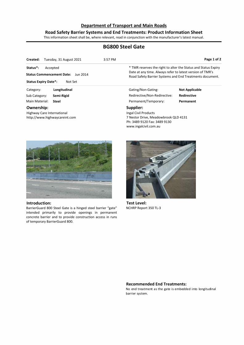
BG800 Steel Gate
Category: Longitudinal
Permanent/Temporary: Permanent
Introduction:BarrierGuard 800 Steel Gate is a hinged steel barrier “gate” intended primarily to provide openings in permanent concrete barrier and to provide construction access in runs of temporary BarrierGuard 800.
Ownership:Highway Care Internationalhttp://www.highwaycareint.com
Supplier:Ingal Civil Products7 Nestor Drive, Meadowbrook QLD 4131Ph: 3489 9120 Fax: 3489 9130www.ingalcivil.com.au
Page 1 of 2
Test Level:NCHRP Report 350 TL-3
Status*: Accepted
Status Commencement Date: Jun 2014
Status Expiry Date*: Not Set
* TMR reserves the right to alter the Status and Status Expiry Date at any time. Always refer to latest version of TMR's Road Safety Barrier Systems and End Treatments document.
Gating/Non-Gating: Not Applicable
Redirective/Non-Redirective: Redirective
Main Material: Steel
Sub Category: Semi-Rigid
This information sheet shall be, where relevant, read in conjunction with the manufacturer's latest manual.Road Safety Barrier Systems and End Treatments: Product Information Sheet
Department of Transport and Main Roads
3:57 PMTuesday, 31 August 2021Created:
Recommended End Treatments:No end treatment as the gate is embedded into longitudinal barrier system.

Design:BarrierGuard 800 Steel Gate is a hinged steel gate comprising 6 metre and 12 metre sections of Barrierguard 800 steel barrier with “T-Top” attachments. The system is 540 mm wide, and 915 mm high. The maximum length of gate is 30 metres (on the basis of operational manageability). The system is tested on longer lengths. The system should be installed on smooth level ground. The intended sweep of the gate should be free from kerbs or rapid changes in gradient. Designer should check with supplier for site specific foundation requirements.
Limitations:Wheels must be fully retracted when not in use. Posted speed should be restricted to 40 km/h when gate is open unless exposed barrier ends can be otherwise shielded.
BG800 Steel Gate Page 2 of 2
References: Australian Standard AS/NZS 3845 NCHRP Report 350 TMR Road Planning and Design Manual Austroads determination letter dated 14 March 2014 NSW RMS Acceptance Document dated 14 March 2014 FHWA letter Ref: HSSD/B-159 dated 8 May 2007
BarrierGuard 800 Installation Manual – Laura Metaal, Version 2.6
Austroads acceptance documents dated 06-Mar-2018 (Steel Gate)
Deflection:Measured (Crash Test) Deflections: Nominal
Mass (kg)
Nominal Angle (deg)
Nominal Speed (km/h)
Recorded Deflection
(m)
Note
2,000 25 100 1.162 1 Note: 1 = NCHRP 350 3-21 test ref. BG807. This test comprised a 60 metre length of “free barrier” between anchors. Shorter lengths between ground anchors are likely to result in lower deflections. Designer should consult with supplier for performance of different configurations.
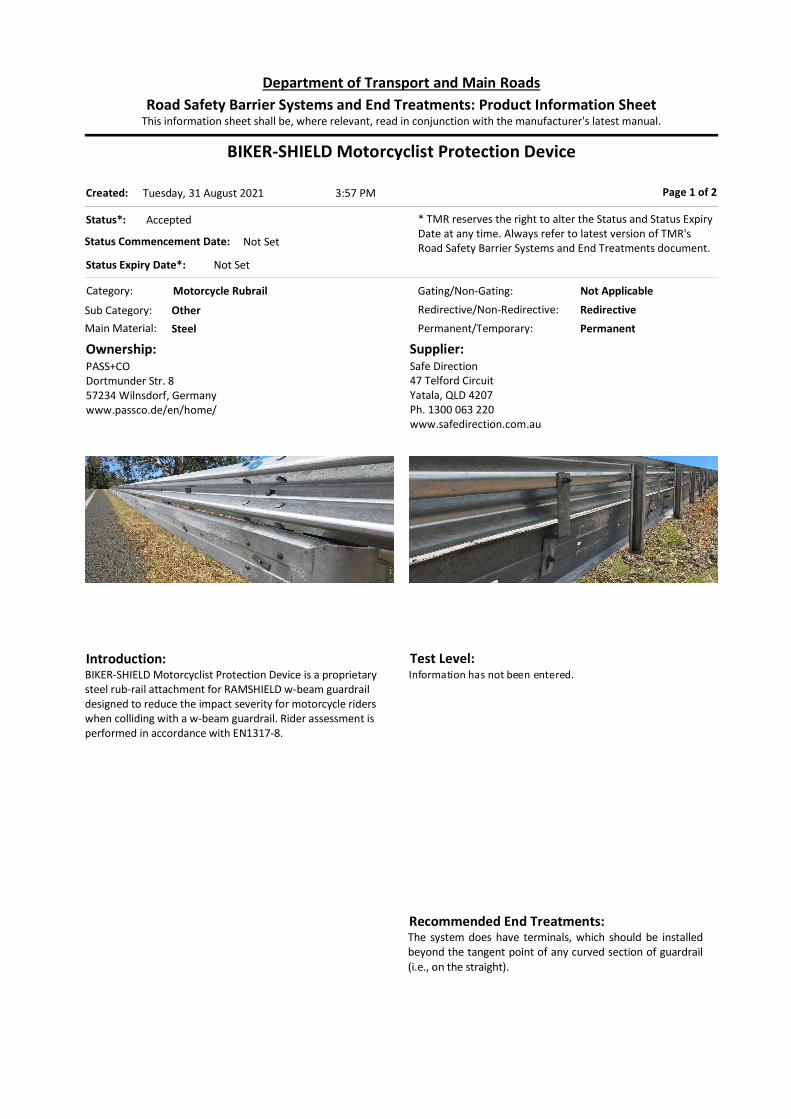
BIKER-SHIELD Motorcyclist Protection Device
Category: Motorcycle Rubrail
Permanent/Temporary: Permanent
Introduction:BIKER-SHIELD Motorcyclist Protection Device is a proprietary steel rub-rail attachment for RAMSHIELD w-beam guardrail designed to reduce the impact severity for motorcycle riders when colliding with a w-beam guardrail. Rider assessment is performed in accordance with EN1317-8.
Ownership:PASS+CODortmunder Str. 857234 Wilnsdorf, Germanywww.passco.de/en/home/
Supplier:Safe Direction47 Telford CircuitYatala, QLD 4207Ph. 1300 063 220www.safedirection.com.au
Page 1 of 2
Test Level:Information has not been entered.
Status*: Accepted
Status Commencement Date: Not Set
Status Expiry Date*: Not Set
* TMR reserves the right to alter the Status and Status Expiry Date at any time. Always refer to latest version of TMR's Road Safety Barrier Systems and End Treatments document.
Gating/Non-Gating: Not Applicable
Redirective/Non-Redirective: Redirective
Main Material: Steel
Sub Category: Other
This information sheet shall be, where relevant, read in conjunction with the manufacturer's latest manual.Road Safety Barrier Systems and End Treatments: Product Information Sheet
Department of Transport and Main Roads
3:57 PMTuesday, 31 August 2021Created:
Recommended End Treatments:The system does have terminals, which should be installed beyond the tangent point of any curved section of guardrail (i.e., on the straight).

Design:Refer to: Product Manual, QTMR Road Panning and Design Manual 2nd Edition
Volume 3 Part 6/Section 6.5.1. System should not be attached to the components of any end treatment. The surface beneath the system must be smooth and free of snag points, kerbs or obstructions that may interfere with the operation of the product.
Limitations:Information has not been entered.
BIKER-SHIELD Motorcyclist Protection Device Page 2 of 2
References: Australian Standard AS/NZS 3845 QTMR RPDM 2nd Edition Volume 3 Part 6 SafeDirection letter dated 18-Dec-2018 Biker-Shield Product and Installation manual, SafeDirection; Ref PM 025/0
Deflection:Information has not been entered.
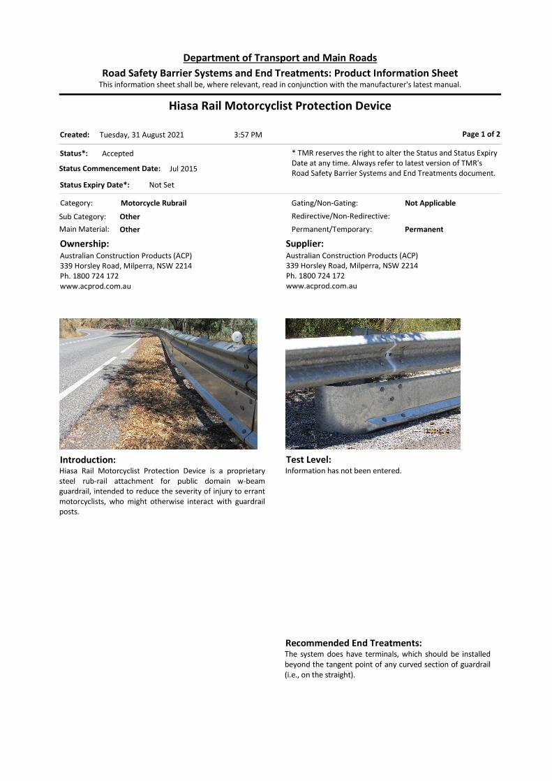
Hiasa Rail Motorcyclist Protection Device
Category: Motorcycle Rubrail
Permanent/Temporary: Permanent
Introduction:Hiasa Rail Motorcyclist Protection Device is a proprietary steel rub-rail attachment for public domain w-beam guardrail, intended to reduce the severity of injury to errant motorcyclists, who might otherwise interact with guardrail posts.
Ownership:Australian Construction Products (ACP)339 Horsley Road, Milperra, NSW 2214Ph. 1800 724 172www.acprod.com.au
Supplier:Australian Construction Products (ACP)339 Horsley Road, Milperra, NSW 2214Ph. 1800 724 172www.acprod.com.au
Page 1 of 2
Test Level:Information has not been entered.
Status*: Accepted
Status Commencement Date: Jul 2015
Status Expiry Date*: Not Set
* TMR reserves the right to alter the Status and Status Expiry Date at any time. Always refer to latest version of TMR's Road Safety Barrier Systems and End Treatments document.
Gating/Non-Gating: Not Applicable
Redirective/Non-Redirective:
Main Material: Other
Sub Category: Other
This information sheet shall be, where relevant, read in conjunction with the manufacturer's latest manual.Road Safety Barrier Systems and End Treatments: Product Information Sheet
Department of Transport and Main Roads
3:57 PMTuesday, 31 August 2021Created:
Recommended End Treatments:The system does have terminals, which should be installed beyond the tangent point of any curved section of guardrail (i.e., on the straight).

Design:Refer to: Product Manual, QTMR Road Panning and Design Manual 2nd Edition
Volume 3 Part 6/Section 6.5.1. System should not be attached to the components of any end treatment. The surface beneath the system must be smooth and free of snag points, kerbs or obstructions that may interfere with the operation of the product.
Limitations:
Hiasa Rail Motorcyclist Protection Device Page 2 of 2
References: Australian Standard AS/NZS 3845 QTMR RPDM 2nd Edition Volume 3 Part 6 ACP letter dated 29-Jun-2015 Austroads acceptance document (12-May-2015) Hiasa Rail manual (version June 2015)
Deflection:Information has not been entered.

Ingal MPR (Motorcyclist Protection Rail)
Category: Motorcycle Rubrail
Permanent/Temporary: Permanent
Introduction:Ingal MPR is a proprietary steel rub-rail attachment for both public domain w-beam guardrail and Ezy-Guard SMART, intended to reduce the severity of injury to errant motorcyclists, who might otherwise interact with guardrail posts.
Ownership:Ingal Civil Products57-65 Airds Road, Minto, NSW 2566Ph: 02 9827 3333Fax: 02 9827 3300www.ingalcivil.com.au
Supplier:Ingal Civil Products7 Nestor Drive, Meadowbrook QLD 4131Ph: 3489 9120 Fax: 3489 9130www.ingalcivil.com.au
Page 1 of 2
Test Level:Information has not been entered.
Status*: Accepted
Status Commencement Date: Jul 2015
Status Expiry Date*: Not Set
* TMR reserves the right to alter the Status and Status Expiry Date at any time. Always refer to latest version of TMR's Road Safety Barrier Systems and End Treatments document.
Gating/Non-Gating: Not Applicable
Redirective/Non-Redirective:
Main Material: Other
Sub Category: Other
This information sheet shall be, where relevant, read in conjunction with the manufacturer's latest manual.Road Safety Barrier Systems and End Treatments: Product Information Sheet
Department of Transport and Main Roads
3:57 PMTuesday, 31 August 2021Created:
Recommended End Treatments:The system does have terminals, which should be installed beyond the tangent point of any curved section of guardrail (i.e., on the straight).

Design:Refer to: Product Manual, QTMR Road Panning and Design Manual 2nd Edition
Volume 3 Part 6/Section 6.5.1. System should not be attached to the components of any end treatment. The surface beneath the system must be smooth and free of snag points, kerbs or obstructions that may interfere with the operation of the product.
Limitations:
Ingal MPR (Motorcyclist Protection Rail) Page 2 of 2
References: AS/NZS 3845 QTMR RPDM 2nd Edition Volume 3 Part 6 Ingal letter dated 17-Jun-2015 Ingal letter dated 18-Jan-2016 Austroads acceptance document (8-Jan-2016) Ingal MPR manual (release 12/15)
Deflection:Information has not been entered.

RiderPro Motorcyclist Protection Device
Category: Motorcycle Rubrail
Permanent/Temporary: Permanent
Introduction:RiderPro Motorcyclist Protection Device is a proprietary steel rub-rail attachment for Sentry w-beam and Sentry Thrie-Beam, intended to reduce the severity of injury to errant motorcyclists, who might otherwise interact with guardrail posts. Rider assessment is performed on RiderPro attached to Sentry w-beam in accordance with CEN/TS 1317-8.
Ownership:Margaritelli Ferroviaria S.p.a.Via Adriatica, 10906135 Ponte San Giovanni (PG), [email protected]
Supplier:Australian Construction Products (ACP)339 Horsley Road, Milperra, NSW 2214Ph. 1800 724 172www.acprod.com.au
Page 1 of 2
Test Level:Information has not been entered.
Status*: Accepted
Status Commencement Date: January 2021
Status Expiry Date*: Not Set
* TMR reserves the right to alter the Status and Status Expiry Date at any time. Always refer to latest version of TMR's Road Safety Barrier Systems and End Treatments document.
Gating/Non-Gating: Not Applicable
Redirective/Non-Redirective: Redirective
Main Material: Steel
Sub Category: Other
This information sheet shall be, where relevant, read in conjunction with the manufacturer's latest manual.Road Safety Barrier Systems and End Treatments: Product Information Sheet
Department of Transport and Main Roads
3:57 PMTuesday, 31 August 2021Created:
Recommended End Treatments:The system does have terminals, which should be installed beyond the tangent point of any curved section of guardrail (i.e., on the straight).

Design:Refer to: Product Manual, TMR Road Panning and Design Manual 2nd Edition
Volume 3 Part 6/Section 6.5.1. System should not be attached to the components of any end treatment. The surface beneath the system must be smooth and free of snag points, kerbs or obstructions that may interfere with the operation of the product.
Limitations:Information has not been entered.
RiderPro Motorcyclist Protection Device Page 2 of 2
References: AS/NZS 3845 CEN/TS 1317-8 TMR Road Planning and Design Manual Austroads acceptance documents (18 Dec 2020) RiderPro Product and Installation Manual (IM 030 Rev 01)
CSI Test TM.1.60 and Test TM.3.60 RiderPro (for Sentry) Reports (2 Aug 2019)
Holmes Solutions Sentry W-Beam with MPR MASH TL-3 Testing Report (July 2020)
Deflection:Information has not been entered.

RaptorTHIS IS NOT A ROAD SAFETY BARRIER
Category: Other
Permanent/Temporary: Permanent
Introduction:The RAPTOR is a proprietary plastic single point protector that may b e used to shield high-risk utility poles or other single point hazards (e.g., trees) where conventional barrier systems may b e impractical. Var iants: Two variants exist: 2.46m x 1.15m x 1.05m (L x W x H) 300mm void 2.76m x 1.15m x 1.05m (L x W x H) 600mm void
Ownership:Valmont Highway [email protected]
Supplier:Valmont Highway Distribution57-65 Airds Road, Minto, NSW 2566Ph: 02 9814 1711www.valmonthighway.com Contact: Leigh BrownEmail: [email protected]
Page 1 of 2
Test Level:Not Applicable.
Status*: Accepted
Status Commencement Date: Not Set
Status Expiry Date*: Not Set
* TMR reserves the right to alter the Status and Status Expiry Date at any time. Always refer to latest version of TMR's Road Safety Barrier Systems and End Treatments document.
Gating/Non-Gating: Not Applicable
Redirective/Non-Redirective: Non-Redirective
Main Material: Other
Sub Category: Other
This information sheet shall be, where relevant, read in conjunction with the manufacturer's latest manual.Road Safety Barrier Systems and End Treatments: Product Information Sheet
Department of Transport and Main Roads
3:57 PMTuesday, 31 August 2021Created:
Recommended End Treatments:Not Applicable.
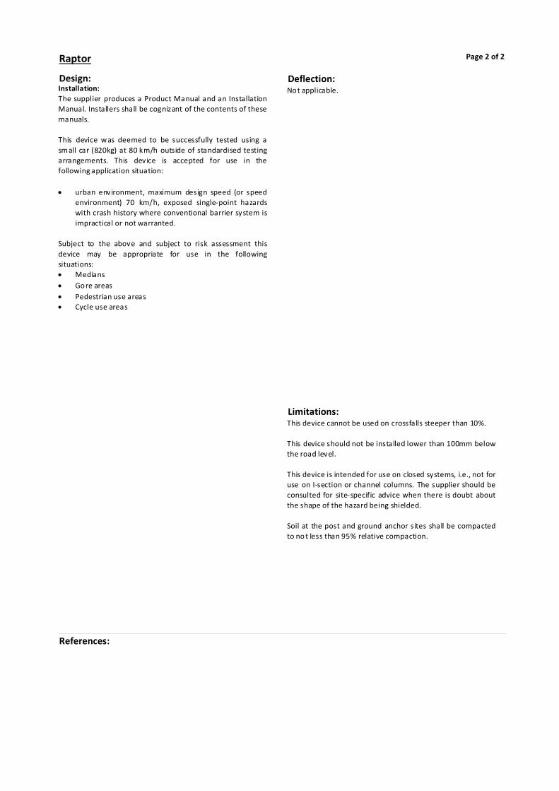
Design:Installation: The supplier produces a Product Manual and an Installation Manual. Installers shall be cognizant of the contents of these manuals. This device was deemed to be successfully tested using a small car (820kg) at 80 km/h outside of standardised testing arrangements. This device is accepted for use in the following application situation: urban environment, maximum design speed (or speed
environment) 70 km/h, exposed single-point hazards with crash history where conventional barrier system is impractical or not warranted.
Subject to the above and subject to risk assessment this device may be appropriate for use in the following situations: Medians Gore areas Pedestrian use areas Cycle use areas
Limitations:This device cannot be used on crossfalls steeper than 10%. This device should not be installed lower than 100mm below the road level. This device is intended for use on closed systems, i.e., not for use on I-section or channel columns. The supplier should be consulted for site-specific advice when there is doubt about the shape of the hazard being shielded. Soil at the post and ground anchor sites shall be compacted to no t less than 95% relative compaction.
Raptor Page 2 of 2
References:
Deflection:Not applicable.