Accepted Manuscript - CentraleSupelec
31
Accepted Manuscript A passivity‐based controller for coordination of converters in a fuel cell system M. Hilairet, M. Ghanes, O. Béthoux, V. Tanasa, J‐P. Barbot, D. Normand‐Cyrot DOI: 10.1016/j.conengprac.2013.04.00397 Reference: Publisher: ELSEVIER To appear in: Control Engineering Practice Received date: 4 September 2012 Accepted date: 4 April 2013 Date of Publication: Available online 14 May 2013 (Volume 21, n° 8, Pages 1097‐1109) Prize for 2011‐13 of the three best papers Please cite this article as: M. Hilairet, M. Ghanes, O. Béthoux, V. Tanasa, J‐P. Barbot, D. Normand‐Cyrot, A passivity‐based controller for coordination of converters in a fuel cell system, Control Engineering Practice, Volume 21, Issue 8, August 2013, Pages 1097‐1109, DOI: 10.1016/j.conengprac.2013.04.003. Document Version: Early version, also known as pre‐print This is a PDF file of an unedited manuscript that has been accepted for publication. As a service to our customers we are providing this early version of the manuscript. The manuscript will undergo copyediting, typesetting, and review of the resulting proof before it is published in its final form. Please note that during the production process errors may be discovered which could affect the content, and all legal disclaimers that apply to the journal pertain.
Transcript of Accepted Manuscript - CentraleSupelec

Accepted Manuscript
A passivity‐based controller for coordination of converters in a fuel cell system
M. Hilairet, M. Ghanes, O. Béthoux, V. Tanasa, J‐P. Barbot, D. Normand‐Cyrot
DOI: 10.1016/j.conengprac.2013.04.00397
Reference:
Publisher: ELSEVIER
To appear in: Control Engineering Practice
Received date: 4 September 2012
Accepted date: 4 April 2013
Date of Publication: Available online 14 May 2013 (Volume 21, n° 8, Pages 1097‐1109)
Prize for 2011‐13 of the three best papers
Please cite this article as: M. Hilairet, M. Ghanes, O. Béthoux, V. Tanasa, J‐P. Barbot, D.
Normand‐Cyrot, A passivity‐based controller for coordination of converters in a fuel cell
system, Control Engineering Practice, Volume 21, Issue 8, August 2013, Pages 1097‐1109, DOI:
10.1016/j.conengprac.2013.04.003.
Document Version: Early version, also known as pre‐print
This is a PDF file of an unedited manuscript that has been accepted for publication. As a service
to our customers we are providing this early version of the manuscript. The manuscript will
undergo copyediting, typesetting, and review of the resulting proof before it is published in
its final form. Please note that during the production process errors may be discovered which
could affect the content, and all legal disclaimers that apply to the journal pertain.
obethoux
Note
A passivity-based controller for coordination of converters in a fuel cell system Control Engineering Practice, Volume 21, Issue 8, August 2013, Pages 1097-1109 M. Hilairet, M. Ghanes, O. Béthoux, V. Tanasa, J-P. Barbot, D. Normand-Cyrot Received 4 September 2012, Accepted 4 April 2013, Available online 14 May 2013 http://dx.doi.org/10.1016/j.conengprac.2013.04.003


A Passivity-Based Controller for coordination
of converters in a Fuel Cell System
M. Hilaireta, M. Ghanesb, O. Bethouxc, V. Tanasad, J-P. Barbotb, D. Normand-Cyrotd
aFEMTO-ST/FCLab, CNRS UMR 6174, Universite de Franche-Comte, F-90010 Belfort, FrancebECS-Lab/ENSEA, 6 Avenue du Ponceau, 95014 Cergy-Pontoise, France
cLGEP/SPEE Labs; CNRS UMR8507; SUPELEC; Univ Pierre et Marie Curie-P6; Univ Paris Sud-P11,91192 Gif sur Yvette, France
dLaboratoire des Signaux et Systemes; CNRS UMR 8506; SUPELEC; Universite Paris-Sud 11;3, rue Joliot Curie, Plateau de Moulon F91192 Gif sur Yvette
e-mail: [email protected]
Abstract
The problem of converters coordination of a fuel cell system involving a hydrogen fuel cell
with supercapacitors for applications with high instantaneous dynamic power is addressed
in this paper. The problem is solved by using a non-linear controller based on passivity. The
controller design is based on the interconnection and damping assignment approach, where
the proof of the local system stability of the whole closed-loop system is shown. Simulation
and experimental results on a reduced scale system prove the feasibility of the proposed
approach for a real electrical vehicle.
Keywords: Fuel cell, supercapacitors, power management, port-controlled Hamiltonian
systems, IDA-PBC methodology, experimentation.
1. Introduction
To comply with environmental norms, the development of electric and hybrid vehicles
has increased since 2009. In this context, the development of a fuel cell (FC) system as
the main source of energy, is considered due to the noise reduction, high efficiency, low
weight, compact size, modularity and controllability. However, this technology has some
weak points, such as cost, reliability and durability. Specifically, to ensure a good health
state of the FC, it is necessary for the FC to deliver a slowly varying current, i.e. a current
slope lower than 4A/s for a 0.5 kW/12.5V FC (Thounthong, Rael and Davat, 2009), and
Preprint submitted to Elsevier April 19, 2013

10A/s for a 20 kW/48V FC (Corbo, Migliardinia and Veneri, 2009a) as examples. Thus,
an FC needs to be associated with other sources which supply short pulse energy and fill
the temporary failure of the FC (Hissel et al., 2008). Nowadays, these auxiliary sources can
either be batteries or supercapacitors (SCs) Sometimes, batteries are not able to bear high
power charge and discharge conditions, whereas supercapacitors have a high power range.
Therefore, for fast power demands, supercapacitors are probably the best-suited components
(Rodatz et al., 2005).
In this paper, the challenging problem of the power management of an hydrogen FC
system associated to a reversible impulse energy source (the supercapacitors) is considered
and involves both practical and theoretical issues. There are several electric architectures
of the hybrid system, which can be classified into three categories : series, cascaded and
parallel (Jiang et al., 2004; Cacciato et al., 2004). The literature has shown that the parallel
architectures are the most suitable ones.
The parallel structures with only one converter (Azib et al., 2010; Davat et al., 2009)
or two converters (Davat et al., 2009) can fully respect the mentioned requirements. This
paper is dedicated to the study of the structure with two converters as shown in Fig. 1.
Nowadays, high-performance and efficiency controllers are readily available (Vahidi, Ste-
fanopoulou and Peng, 2006; Thounthong, Rael and Davat, 2009; Thounthong et al., 2009b;
Azib et al., 2009a,b; Arce, del Real and Bordons, 2009). These allow to the current, delivered
by the FC, to have smooth behavior in order to ensure its life time, while the SCs provide
DC/DC
DC/DC
vb
isc
vsc
vfc
ifcC
il
FC
SCs
Figure 1: Two converters parallel structure studied in this work.
2

the load power transient (Arce, del Real and Bordons, 2009; Thounthong et al., 2009b).
Unfortunately, the closed-loop system stability of these controllers are generally not proved
theoretically, although they are effective.
Therefore, this drawback opens a theoretically challenging problem. In this work, a
non-linear controller based on the Interconnection and Damping Assignment - Passivity
Based Control (IDA-PBC) has been studied in order to prove the local asymptotic stability
of the whole closed-loop system, while maintaining the same objectives and components
security as standard controllers, i.e. the controller has to sustain the bus voltage and the
supercapacitors voltage at desired levels without compromising the FC operation as the fuel
starvation during fast load change which refers to an operation with an insufficient amount
of gas in the active layer (Yousfi-Steiner et al., 2009).
This paper is divided into four sections as follows: section two describes some standard
power management controllers based on a frequency decoupling of the sources. The proposed
passivity-based controller is detailed in section three; in section four simulation results are
presented. Finally, the approach has been applied to a reduced scaled test bench system
based on the Nexa Ballard fuel cell. Furthermore, section V deals with the implementation
and experimental results.
2. Power management
The power management must comply with the load power demands and to provide an
effective fuel cell control while decreasing the fuel consumption. Also it has to prevent the
fuel starvation during fast load demands, to maintain the DC bus and state of charge of the
supercapacitors constant and to ensure the proper use of each component.
The main objective of the control strategies is to regulate the DC bus voltage with the FC
as the primary power source (Davat et al., 2009). However, fuel cell performances (efficiency,
degradation, aging effects) are influenced by many environmental and application constraints
(Wahdame et al., 2008). These aging tests prove that limiting the load dynamic effects can
save the FC performances and raise its durability. Therefore, it seems clear that the DC bus
regulation has to be managed by the supercapacitors. A short survey reveals a significant
3

number of strategies, like the one based on the state-feedback (Jiang et al., 2004), fuzzy
logic (Kisacikoglu, Uzunoglu and Alam, 2009; Martinez et al., 2011), proportional-integral
controllers (Azib et al., 2010), RST controller (Caux et al., 2005), passivity (Becherif, 2006),
flatness (Zandi et al., 2011) or model predictive control (Vahidi, Stefanopoulou and Peng,
2006). Alternative approach exist such as optimal control (Rodatz et al., 2005), dynamic
programming (Brahma, Guezennec and Rizzoni, 2000) or empirical control associated with a
multi objective genetic algorithm optimization (Paladini et al., 2007) that has been applied
for the supervisory power train control problem in charge sustaining hybrid electric vehicles.
However, these approaches are based on the a priori knowledge of the power load, thus
real-time control is not straightforward implementable.
In (Azib et al., 2011), a two converters structure control strategy has been detailed. It
relies on the control of the converter in such a way to split the demanded power between
the FC and SCs. The converter-parameter tuning is based on a frequency decoupling so
that to coordinate the two sources without compromising the FC operation. The DC bus
capacitor filters the high frequencies (i.e. above the kHz), the SCs associated with their
converters provide the medium frequencies (from 1 kHz to 1Hz), and the FC ensures the low
frequencies (less than 1Hz). This frequency decoupling of the sources naturally induces a
power management strategy based on cascaded loops and the control is effective (Azib et al.,
2011). The gains are tuned to ensure the closed-loop system stability, although it has not
been theoretically proved. Therefore, this drawback seems to be a theoretically challenging
problem, while maintaining the same objectives and the component security. Therefore,
in this work a passivity-based controller, which relies on the well-known IDA-PBC method
(Ortega et al., 2002; Ortega and Garcia-Canseco, 2004; Ortega et al., 2008), has been studied
in order to prove the asymptotic stability of the outer closed-loop system and finally the
local asymptotic stability of the whole system.
In (Becherif, 2006) a full order IDA-PBC has been designed for a similar system. How-
ever, currents ifc and isc can exceed the maximum value allowed, because they are not
directly controlled. This point is generally mandatory for industrial applications; it is the
reason why the strategy proposed in this paper comprises two loops as shown in Fig. (2). To
4

be more precise, there are two inner current loop controllers for the FC and SCs respectively,
based on PI controllers and only one outer loop which controls the DC bus voltage and state
of charge of the SCs. In this work, the outer-loop controller is based on passivity approach.
3. Passivity-based controller
3.1. Port controlled Hamiltonian system
The PBC defines a controller design methodology that stabilizes the system by making
it passive. Although there are many variations on this basic idea, the PBC can be broadly
classified into two major groups. In the “regular” PBC, the designer chooses the storage
function (usually quadratic), and then designs the controller that makes the storage function
non-increasing (Cecati et al., 2003). In the second PBC methodology, the storage function
of the closed-loop system remains free. The designer selects a control structure, such as La-
grangian, port-controller Hamiltonian (PCH) or Brayton-Moser formulation (Weiss, Mathis
and Trajkovic, 1998; Jeltsema and Scherpen, 2003; Zhou, Khambadkone and Kong, 2009),
and then, characterizes all assignable energy or power functions. The most notable examples
of this approach are the controlled Lagrangian systems, and the IDA-PBC (Van der Schaft,
1996; Ortega et al., 2002; Ortega and Garcia-Canseco, 2004; Ortega et al., 2008). It is the
latter method that has been chosen in this work.
Firstly, the IDA-PBC approach consists in identifying the natural energy function of the
system called H(x). Rewriting a non-linear system:
x = f(x) + g(x)u; x ∈ �n; u ∈ �m
y = h(x); y ∈ �m
versus the gradient of the energy function:
∇H(x) =[
∂H∂x1
(x) ∂H∂x2
(x) ... ∂H∂xn
(x)]T
leads to PCH form as follows:
x = [J (x)−R(x)]H(x) + g(x)u
y = gT (x)∇H(x)
5

where y is the output, J (x) = −J T (x) is a skew-symmetric matrix of dimension n × n
representing the interconnections between states, and R(x) = RT (x) ≥ 0 is a positive
semi-definite symmetric matrix representing the natural damping of the system.
3.2. The IDA-PBC Methodology
Let us consider the system (Ortega and Garcia-Canseco, 2004; Ortega et al., 2008)
x = f(x) + g(x)u (1)
and assume there are matrices Jd(x) = −J Td (x), Rd(x) = RT
d (x) ≥ 0 and a function
Hd(x) : �n −→ � so that the closed-loop system (1) with control variable u
u =[gT (x)g(x)
]−1gT (x) {[Jd(x)−Rd(x)]∇Hd − f(x)}
takes the PCH form x = [Jd(x)−Rd(x)]∇Hd (2)
Hd(x) is such that x∗ = argminx∈�n(Hd(x)) with x∗ ∈ �n the (locally) equilibrium to be
stabilized. The system is asymptotically stable if, in addition, x∗ is an isolated minimum
of Hd(x) and if the largest invariant set under the closed-loop dynamics (2) contained in{x ∈ �n | [∇Hd]
T Rd(x)∇Hd = 0}equals x∗.
The stability of x∗ is established noting that, along the trajectories of (2), we have
Hd = − [∇Hd]T Rd(x)∇Hd ≤ 0
Hence, Hd(x) is qualified as a Lyapunov function. Asymptotic stability immediately follows
invoking the La Salle’s invariance principle (LaSalle, 1960). Finally, to ensure that the
solutions remain bounded, we give the estimate of the field of attraction as the largest
bounded level set of Hd(x).
3.3. Hybrid system modeling
Fuel cell modeling. The model used is a static model (Pukrushpan, Peng and Stefanopoulou,
2004) where the FC voltage vfc is computed according to the current stack ifc by a 5th order
polynomial function as shown in Fig. (3). The data fitting has been obtained according to
experimental results.
6

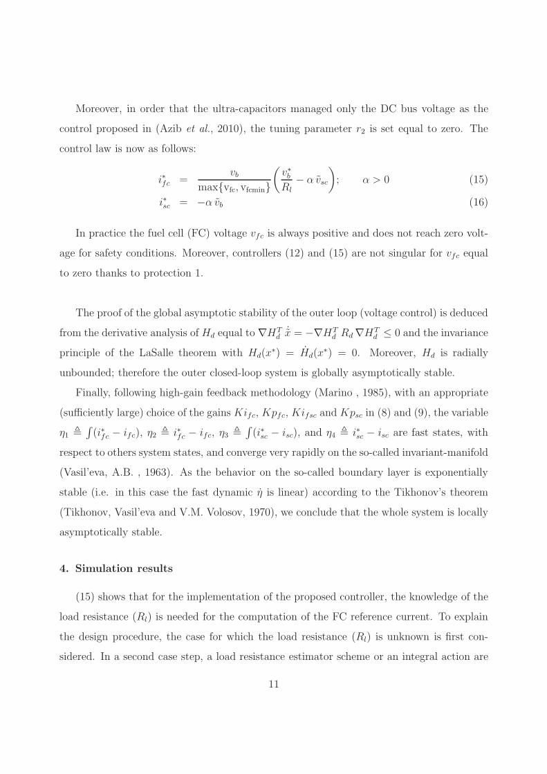
SCs boost converter. SCs can be charged or discharged; therefore the storage elements are
connected to the DC bus through a reversible power converter as shown in Fig. (4). The
boost converter is controlled by binary input w2(t). We define α2 as the duty cycle of the
control variable w2(t). The second sub-system is represented by an average model as follows
: ddtisc(t) = 1
Lsc
(− (1− α2(t)) vb(t) + vsc(t))
ddtvsc(t) = − isc(t)
Csc
FC boost converter, DC bus and load model. To use the FC in an electric power system,
a boost converter must increase the FC voltage, because the FC voltage is often less than
the DC bus voltage. The boost converter represented in Fig.(4) is controlled by binary
input w1(t). Defining α1 as the duty cycle of control variable w1(t), this subsystem can be
represented by its average model (here, the switches are regarded as ideal) :
ddtifc = 1
Lfc
(− (1− α1(t)) vb(t) + vfc(t))
ddtvb(t) = 1
C
((1− α1(t)) ifc(t) + (1− α2(t)) isc(t)− il(t)
)
where vb(t) is the DC link voltage, vfc(t) is the FC voltage, il(t) is the DC current delivered
to the load and ifc(t) is the FC current.
In our work, the load is modeled by a variable resistance circuit (Rl(t)), whose value
varies according to the power required by the load. The average model is:
ddtil(t) = 1
L
(− Rl(t)il(t) + vb(t))
where inductance L is not part of the load and represents the imperfections of the system.
The load model could have been replaced by a current source il(t) and the same approach
described later could be adopted (see appendix 3).
Complete model. It follows that the complete “fuel cell - supercapacitors” system is repre-
sented by the 5th order non-linear state space model :
7

d
dtvb(t) =
(1− α1(t)) ifc(t) + (1− α2(t)) isc(t)− il(t)
C(3)
d
dtvsc(t) = −isc(t)
Csc(4)
d
dtil(t) =
−Rl(t) il(t) + vb(t)
L(5)
d
dtifc(t) =
−(1 − α1(t)) vb(t) + vfc(t)
Lfc(6)
d
dtisc(t) =
−(1 − α2(t)) vb(t) + vsc(t)
Lsc
(7)
with state space x(t) = [vb; vsc; il; ifc; isc]T , control inputs u(t) = [u1; u2]
T = [1 − α1; 1 −α2]
T , measures y(t) = x and vfc.
Outer loop model (reduced model). The system of 5 equations (3 to 7) is called a singular
perturbed system, because of the difference of time scale between the voltages and the currents
(Kokotovi et al., 1986). Therefore, the system (3 to 7) is forced into current-controlled mode
using a fast inner current loop. More precisely, the following PI current controllers associated
with a anti-windup scheme
u1 = Kifc
∫ t
0
(i∗fc − ifc)dt +Kpfc(i∗fc − ifc) (8)
u2 = Kisc
∫ t
0
(i∗sc − isc)dt +Kpsc(i∗sc − isc) (9)
are used to force ifc and isc to track their respective references i∗fc and i∗sc and produce
fast responses when large feedback gains are used. The control u1 and u2 act as high-gain
feedback, for more details see for example (Marino , 1985).
Consider (6) and (8) for Kifc and Kpfc sufficiently large with respect to voltage and
load dynamics. After transient (convergence), one get ifc − i∗fc = 0 and∫ t
0(i∗fc − ifc) =
vfcvbKifc
.
These imply that (8), after transient, becomes u1 =vfcvb. The same argument is used for (7)
and (9), where after transient, one get u2 =vscvb. Consequently after transient, by replacing
the new obtained u1 and u2 in (3), and currents ifc-isc by their references i∗fc-i∗sc in (3) and
(4) as a new inputs, it follows thatddtvb(t) = 1
C
( vfc(t)
vb(t)i∗fc(t) +
vsc(t)vb(t)
i∗sc(t)− il(t))
ddtvsc(t) = − i∗sc(t)
Csc
ddtil(t) = −Rl(t) il(t)+vb(t)
L
(10)
8

with xr(t) = [x1; x2; x3]T = [vb; vsc; il]
T , control inputs ur = [i∗fc; i∗sc]
T , measures yr and zr
as yr = [vb; vsc; il]T and zr = [ifc; isc; vfc]
T .
Remark 1: In the sequel, the outer closed-loop control is designed by using the model
(10) such that its dynamic is slower than the dynamic of the PI fast actuators (8-9).
3.4. IDA-PBC outer loop controller design
The main objective of IDA-PBC is to assign the state point xr = [x1; x2; x3]T =
[vb; vsc; il]T to the desired equilibrium one x∗
r = [v∗b ; v∗sc;
v∗bRl], with v∗b and v∗sc the DC bus
and SCs desired voltages, by tacking into account the following constraint and protection:
• Constraint 1 : the FC has to prevent stack stresses during power transients.
• Protection 1 : the FC voltage vfc has to be no less than a minimum value vfcmin.
According to section (3.2), the IDA-PBC methodology looks for an energy function Hd so
that its minimum is reached at the desired equilibrium point x∗r . This energy function Hd is
chosen asHd =12xr
T Q xr with xr = xr−x∗r and Q = diag(C,Csc,L). In these circumstances,
writing the PCH system in terms of the dynamics of the error and the gradient of desired
closed-loop energy function ∇Hd is:
˙xr = [J −R]∇Hd + A(ur, xr, x∗r , zr) (11)
with
J −R =
⎡⎢⎢⎢⎣
0 0 − 1LC
0 0 0
1LC
0 −Rl
L2
⎤⎥⎥⎥⎦ , ∇Hd =
⎡⎢⎢⎢⎣
C vb
Csc vsc
L il
⎤⎥⎥⎥⎦
At =[
1C(vfcvb
i∗fc +vscvb
i∗sc − i∗l );− 1Csc
i∗sc; 0]
Solving the algebraic equation in Jd(x) and Rd(x) with the constraint of skew-symmetry and
positive semi-definiteness of Jd(x) and Rd(x) respectively, with the two unknown matrices
equal to:
Jd =
⎡⎢⎢⎢⎣
0 J12 J13
−J12 0 J23
−J13 −J23 0
⎤⎥⎥⎥⎦ , Rd =
⎡⎢⎢⎢⎣
r1 0 0
0 r2 0
0 0 r3
⎤⎥⎥⎥⎦
9

leads to the matching equations:
−r1Cvb + J12Cscvsc + J13Lil = − 1
Cil +
1
C
(vfcvb
i∗fc +vscvb
i∗sc − i∗l
)
−J12Cvb − r2Cscvsc + J23Lil = − 1
Csc
i∗sc
−J13Cvb − J23Cscvsc − r3Lil =1
Lvb − Rl
Lil
One solution is r3 = Rl
L2l, J13 = − 1
CL, and J23 = 0 with r1 > 0 and J12 < 0, which leads
to the non-linear control law:
i∗fc =vb
max{vfc, vfcmin}(v∗bRl
+ Csc(CJ12 − vscvb
Cscr2) vsc − C(vscvb
CscJ12 + r1C)vb
)(12)
i∗sc = Csc(CJ12 vb + r2Csc vsc) (13)
so that the closed-loop system responds to the following dynamics:
˙xr = [Jd −Rd]∇Hd (14)
with
Jd =
⎡⎢⎢⎢⎣
0 J12 − 1LC
−J12 0 0
1LC
0 0
⎤⎥⎥⎥⎦ ,Rd =
⎡⎢⎢⎢⎣
r1 0 0
0 r2 0
0 0 Rl
L2
⎤⎥⎥⎥⎦
The analysis of the control (12)-(13) shows that SCs supply energy due to an error on
the DC bus voltage; the error itself is caused by power spikes or a variation of the DC bus
voltage reference. The desired FC current (i∗fc) shows that the FC supply satisfies two main
objectives :
• the permanent power flow from the FC to the load,
• the energy contribution to regulate the SCs voltage.
Obviously, it does not seem judicious that the FC current participates in the control of
the DC bus voltage according to constraint 1. So, tuning parameters r1 and J12 are set equal
to x2 αx1C2 and − α
CCscwith α > 0, such that the right hand side of (12) is canceled.
10
Moreover, in order that the ultra-capacitors managed only the DC bus voltage as the
control proposed in (Azib et al., 2010), the tuning parameter r2 is set equal to zero. The
control law is now as follows:
i∗fc =vb
max{vfc, vfcmin}(v∗bRl
− α vsc
); α > 0 (15)
i∗sc = −α vb (16)
In practice the fuel cell (FC) voltage vfc is always positive and does not reach zero volt-
age for safety conditions. Moreover, controllers (12) and (15) are not singular for vfc equal
to zero thanks to protection 1.
The proof of the global asymptotic stability of the outer loop (voltage control) is deduced
from the derivative analysis of Hd equal to ∇HTd˙x = −∇HT
d Rd∇HTd ≤ 0 and the invariance
principle of the LaSalle theorem with Hd(x∗) = Hd(x
∗) = 0. Moreover, Hd is radially
unbounded; therefore the outer closed-loop system is globally asymptotically stable.
Finally, following high-gain feedback methodology (Marino , 1985), with an appropriate
(sufficiently large) choice of the gains Kifc, Kpfc, Kifsc and Kpsc in (8) and (9), the variable
η1 �∫(i∗fc − ifc), η2 � i∗fc − ifc, η3 �
∫(i∗sc − isc), and η4 � i∗sc − isc are fast states, with
respect to others system states, and converge very rapidly on the so-called invariant-manifold
(Vasil’eva, A.B. , 1963). As the behavior on the so-called boundary layer is exponentially
stable (i.e. in this case the fast dynamic η is linear) according to the Tikhonov’s theorem
(Tikhonov, Vasil’eva and V.M. Volosov, 1970), we conclude that the whole system is locally
asymptotically stable.
4. Simulation results
(15) shows that for the implementation of the proposed controller, the knowledge of the
load resistance (Rl) is needed for the computation of the FC reference current. To explain
the design procedure, the case for which the load resistance (Rl) is unknown is first con-
sidered. In a second case step, a load resistance estimator scheme or an integral action are
11

added in order to consider the load variation.
Remark 2: In a practical application, when the controller is implemented by a com-
puter, the system is placed in a sampled-data context. Consequently, the passivity based
controller has been simulated and implemented through a zero order holder device (emula-
tion process) with a sampling-time equal to 500μs.
4.1. The case of a unknown parameter
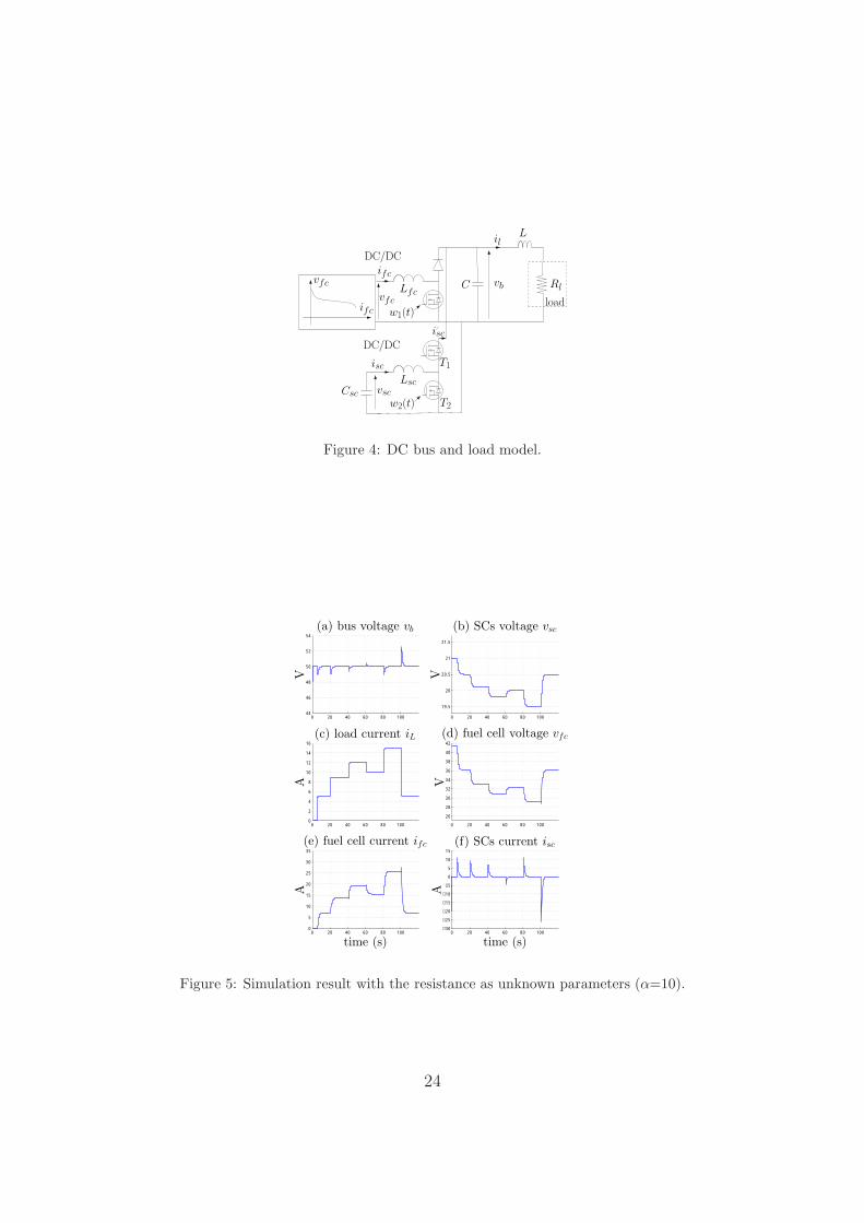
Fig. (5) represents a scenario where the reference DC bus voltage is set equal to 50V
and the load current varies between 0 and 15A. This power cycle is representative of a
reduced-scale vehicle power demand, where the load requirement consists in raising and
lowering power edges between 0 and 750W. Here, the load resistance (Rl) is considered
as a fixed parameter (the arbitrary admittance used in the controller equation is equal to
5A/50V= 0.1 S). The control strategy provides an insufficient FC current reference during
the time interval [21, 101] s and consequently, the SCs provide most of the power during the
high power transient and do not recover their equilibrium points, despite the fact that the
FC current transient is good.
To cope with this problem, two solutions are explored. In the first one, an estimate of
the load resistance is added to the command value i∗fc, while in the second approach, a low
integrator action eliminates this error.
4.2. IDA-PBC controller + load resistance estimator
In this paragraph an estimator of the load impedance Yl = 1/Rl is considered to deal
with this problem, as follow:
Yl =KRl
s+KRl.ilkvbk
(17)
where the tuning parameter KRl control the sensibility of the fuel cell current reference.
Fig. (6) shows the estimator behavior. In this application, KRl has been selected in order to
obtain a slow time response of about 6 s, so that the FC current reference reacts smoothly.
12

Fig. (7) depicts the global system performances. In this simulation the load resistance
estimate is used in the controller. With the former estimator parameter set (KRl = 0.5),
the FC current variation is less than 4A/s. It indeed respects the FC specifications. This
controller architecture also leads to a nearly zero static error of the SCs voltage without
adding any integral action. Nevertheless, a low integral action needs to be added in a
practical application to compensate for the converter losses.
Remark 4: The proof of the global stability of the system composed of the controller,
the estimator and electrical sub-system (10) invoking a theorem on stability of cascaded
systems stated in (Panteley and Loria, 1998) can be found in appendix 2.
4.3. IDA-PBC controller + integral action
The controller design supposes that the converters are loss-less. So in practice, a low
integrator action needs to be added to the passivity controller in order to ensure zero SCs
voltage error at steady state and to counteract the unknown load resistance consequences
(Donaire and Junco, 2009). The controller equations are now:
ui = −γ vsc; γ > 0 (18)
i∗fc =vb
max{vfc, vfcmin}( v∗bRl
− α vsc + Cui
); α > 0 (19)
i∗sc = −α vb (20)
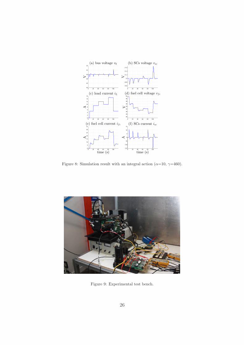
Fig. (8) shows the system response. It shows that the DC bus and SC voltages reach
the desired equilibrium point. Moreover, this controller allows the FC to have a smooth
response during fast power demand of the load (8.e), which improves the state of health of
the FC.
The tuning of non-linear controllers such as PBC is not obvious and trivial. To analyze
the influence of the tuning parameters on the closed-loop system, more specifically on the
FC current dynamics, some simulations have been done. In practice, increasing gamma leads
to an under-damping closed-loop system, while increasing alpha gives for the FC current
bigger slopes. After trial and error loops, a reasonable choice for (α, γ) is (10, 460). Instead
of a manual tuning that not ensures an efficient control, IDA-PBC and loop optimization
software could be used to ensure consistent results.
13

Remark 3: All the stability properties of x∗ are preserved by adding to the IDA control
an integral term. Here the proof is omitted due to the lack of place and can be found in the
appendix 2.
5. Experimental results
5.1. Test bench description
The hybrid test bench is presented in Fig. 9. The considered FC is a 46A/1200W
Nexa FC designed by Ballard. This latter is composed of 46 cells. The transient auxiliary
source consists of two Maxwell SC modules associated in series: each module is built with the
connection of six individual elements in series [2.7V, 350F]. This SCs device is interconnected
to the DC bus using a chopper built with standard MOS modules and a switching frequency
of the PWM set to 20 kHz (Azib et al., 2010).
The hybrid power source is connected to a programmable electronic load (Hocherl &
Hackl, model ZS1806), which has a rated power of 1800W (imax=150A/Vmax=60V). This
load emulates vehicle power consumption, and is directly monitored by the dSPACE DS1103
real-time board. Finally, table 1 summarize the electric characteristics of the on-board power
sources.
The current inner control loops, which generate the duty cycle α1 and α2, have been
implemented with digital PI controllers updated at 20 kHz. The voltage outer control loops
have a sampling time equal to 2KHz.
5.2. Result analysis
Experiments have been performed on the experimental setup to validate the previously
explained control strategies. The reference DC bus voltage is set equal to 50V, and the load
current varies between 0 and 15A (this is equivalent to a variation of the load admittance
1/Rl from 0 to 0.3 S).
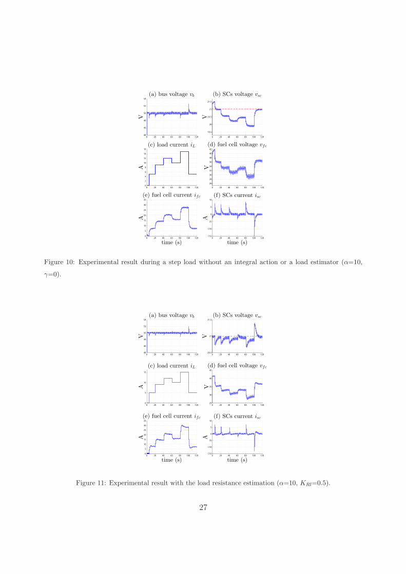
The case of an unknown parameter. Fig. (10.a) shows that the control ensures perfect
control of the DC bus voltage, the SCs respond rapidly to fast load current transients in
14

order to provide most of the power required by the load and to maintain the DC bus voltage
at its reference value. This allows the FC to have a smooth response during fast power
demand of the load (Fig. 10.e), which improves his state of health. Then gradually with
the FC current increasing, the SCs discharge, characterized by the decrease of its voltage,
vanishes to zero (see Fig. 10.e).
The SCs voltage is however not regulated to the reference value equal to 21V, and de-
pends on the load power since the IDA-PBC controller assumes the load resistance as con-
stant (here, the arbitrary admittance used in the controller equation is equal to 5A/50V=
0.1 S). Under these conditions, SCs provide too much energy during the power transition
and SCs recharging is uncertain.
IDA-PBC controller + load resistance estimator. The latter experiment show that the SCs
do not recover their equilibrium points while the load current increases, because of the
inadequate value of the load resistance used in the controller. To overcome this problem,
two solutions have been explored. First, the admittance (Yl = 1/Rl) of the load is estimated
on-line according to Equ. (17).
Fig. 11 shows the whole system behavior where the load resistance estimate is used in
the controller. This controller architecture also leads to a nearly zero static error of the SCs
voltage. However, we can note that the SC voltage is not perfectly equal to its reference at
steady state. This is due to the FC converter losses. Nevertheless, a low integral action or a
converter-losses estimation could be added in a practical application to compensate for the
converter losses.
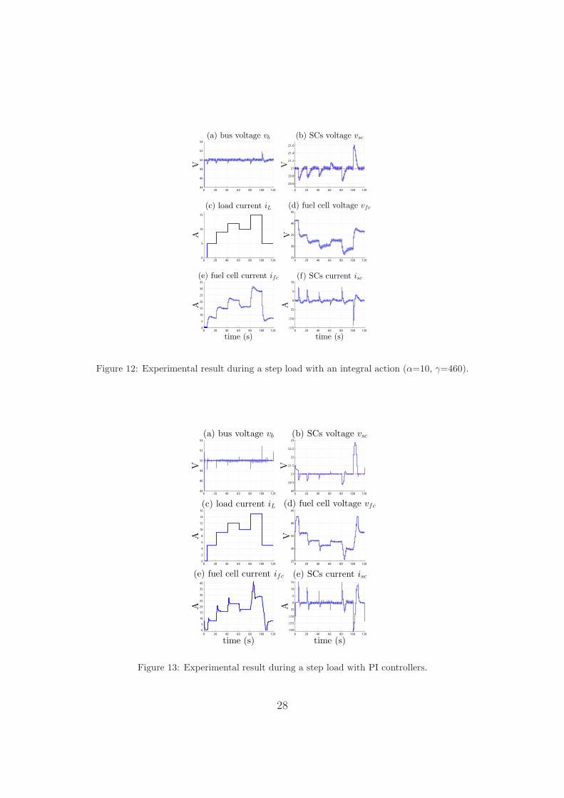
IDA-PBC controller + integral action. The second experiment shown in Fig. (12) was
carried out to validate the proposed strategy with an integral action. Note that the DC bus
and SC voltages are well regulated in spite of the very fast dynamics of power demand. Each
time the power load varies, SC current is positive (respectively negative) during an increase
(respectively decrease) of the power load. In such a situation, the SC voltage continuously
fluctuates around its constant reference value v∗sc set to 21V, as shown in Fig. (12.b). The
experimental results confirm that the association of the FC and the SCs mitigates the FC
15

current transient in order to increase the FC lifespan. Moreover, the experimental results
are consistent with the simulation ones.
PI controller. For comparison, an experiment with PI controllers for the two outer-loops
have been done based on the design proposed in (Azib et al., 2011), as shown on Fig. (13).
Fig. (13.a) shows that the DC bus is well controlled due to greater SCs current compared
to the previous results. Therefore, the fluctuation of the SCs voltage is more important.
Finally, simulation and experimental result show that the passivity-based controller and
PI controller have almost the same performance. However, the new control law based on
passivity ensures a locally asymptotic stability of the whole closed-loop system that is not
demonstrated for PI controllers and these latter have 4 tuning parameters (Kpfc, Kifc, Kpsc, Kisc)
compared to only 2 tuning parameters ((α, γ) or (α,KRl)) for the passivity-based controller,
which makes the implementation of the IDA-PBC on a real-time system easier.
6. Conclusion
In this paper, a new control strategy to manage the energy between two power sources,
namely a hydrogen fuel cell and supercapacitors has been discussed. This new control law
based on passivity ensures a locally asymptotic stability of the whole closed-loop system,
while reducing the load stress on the stack power transients. In addition, this outer voltage
controller has only 2 tuning parameters ((α, γ) or (α,KRl)), which makes the implementation
on a real-time system easier.
As the controller needs the information on the load resistance, the paper has proposed two
alternative solutions : to add an integral action or a load resistance estimator. In both cases
the FC dynamic can be easily tuned while the SCs state of charge is well regulated in steady
state. Simulation and experimental results are consistent, and the controller performances
validate the proposal.
As mentioned previously in section II, passivity based controllers have been proposed
for similar systems where the converter is directly control. The lack of a separate current
control loop makes it difficult to achieve current limitation which is mandatory in industrial
16

applications for hardware protection. It means that the current is measured but not con-
trolled. The proposed PBC with cascaded loops protects the sources, the converters and the
load as regular controllers. Finally, the controller leads to a general non-linear PI controller
that extends the theory with regular PI controllers and gives confidence in the stability with
almost the same experimental performances as regular controller.
It is difficult for the fuel flow to follow the current steps, which decreases the lifespan
of the FC. Therefore, synchronization between the FC controller, the FC converter and the
SC converter is mandatory. In order to extend this work, a future study could investigate
the introduction of a more complicated modelling of the FC, i.e. adding the air compressor
dynamic and studing its impact on the controller design and system performances. It follows
that local or global design control of each components needs further investigations.
Finally, the parallelism of N-sources leads to a redundancy and therefore improves the
reliability and efficiency of the whole system (Malaize and Dib, 2011; De Bernardinis et
al., 2012). Challenging control issues could investigate the generalization of this works to
N-parallel connected sources with different or same characteristics leading to switching-
controller according the state of charge (SoC) and state of health (SoH) of each source.
References
Arce, A., del Real, A.J., & Bordons, C. (2009), “MPC for battery/fuel cell hybrid vehicles including fuel
cell dynamics and bettery performance improvement,” Journal of process control, 19, 1289-1304.
Azib, T., Bethoux, O., Remy, G., & Marchand, C. (2009a), “Structure and Control Strategy for a Parallel
Hybrid Fuel Cell/Supercapacitors Power Source,” IEEE VPPC’09, Dearborn, Michigan, 1858-1863.
Azib, T., Bethoux, O., Marchand, C., & Berthelot, E. (2009b), “Supercapacitors for Power Assistance in
Hybrid Power Source with Fuel Cell,” IEEE Industrial Electronics Society Conference IECON’09, Porto,
Portugal, 3747-3752.
Azib, T., Bethoux, O., Remy, G., & Marchand, C. (2010), “An innovative control strategy of a single
converter for hybrid fuel cell/supercapacitors power source,” IEEE Transactions on Industrial Electronics,
57(2), 4024-4031.
Azib, T., Bethoux, O., Remy, G., & Marchand, C. (2011), “Saturation Management of a Controlled Fuel-
Cell/Ultracapacitor Hybrid Vehicle,” IEEE Transactions on Vehicular Technology, 60(9), 4127 -4138.
17

Becherif, M. (2006), “Passivity-based control of hybrid sources : fuel cell and battery,” 11th IFAC Symposium
on Control in Transportation Systems, The Netherlands.
Brahma, A., Guezennec, Y., & Rizzoni, G. (2000), “Optimal energy management in series hybrid electric
vehicles,” American Control Conference, 1(6), 60-64.
Cacciato, M., Caricchi, F., Giuhlii, F., & Santini, E. (2004), “A critical evaluation and design of bi-directional
DC/DC converters for supercapacitors interfacing in fuel cell applications,” IEEE Industry Applications
Conference (IAS), 2, 1127-1133.
Caux, S., Lachaize, J., Fadel, M., Shott, P., & Nicod, L. (2005), “Modelling and control of a Fuel Cell
System and Storage Elements in transport applications,” Journal of Process Control, 15, 481-491.
Cecati, C., Dell’Aquila, A., Liserre, M., & Monopoli, V.G. (2003) “A passivity-based multilevel active recti-
fier with adaptive compensation for traction applications”, IEEE Transactions on Industry Applications,
39,(5), 1404-1413.
Corbo, P., Migliardinia, F., & Veneri, O. (2009),“PEFC stacks as power sources for hybrid propulsion
systems,” International Journal of Hydrogen Energy, 34(10), 4635-4644.
Yousfi-Steiner, N. Mocoteguy, Ph., Candusso, D., Hissel, D., “A review on polymer electrolyte membrane
fuel cell catalyst degradation and starvation issues: Causes, consequences and diagnostic for mitigation,”
Journal of Power Sources, 194(1), 130-145.
Davat, B., Astier, S., Azib, T., Bethoux, O., & all (2009), “Fuel cell-based hybrid systems,” Electromotion
- EPE chapter ’electric drives’, Lille, France, 1-11.
Donaire, A., & Junco, S. (2009) “On the addition of integral action to port-controlled Hamiltonian systems,”
Automatica, 45(8), 1910-1916.
Hissel, D., Turpin, C., Astier, S., Boulon, L., & all (2008), “A review on existing modeling methodologies for
PEM fuel cell systems,” Fundamentals and developments of fuel cells cenference, FDFC, Nancy, France,
1-30.
Isidori, A. (1995) “Nonlinear control systems,” Springer, Third edition.
Jeltsema, D., & Scherpen, J.M.A. (2003) “A dual relation between port-Hamiltonian systems and the
Brayton-Moser equations for nonlinear switched RLC circuits,” Automatica, 39(6), 969-979.
Jiang, Z., Gao, L., Blackwelder, M.J., & Dougal, R.A. (2004), “Design and experimental tests of control
strategies for active hybrid fuel cell/battery power sources,” Journal of Power Sources, 130, 163-171.
Kisacikoglu, M.C., Uzunoglu, M., & Alam, M.S. (2009), “Load sharing using fuzzy logic control in a fuel
cell/ultracapacitor hybrid vehicule,” International Journal of Hydrogen Energy, 34, 1497-1507.
Kokotovic, P., Khalil, H., & O’Reilly, J., (1986), “Singular perturbation methods in control: Analysis and
design,” Academic Press, New-York.
LaSalle, J.P. (1960), “Some extensions of Lyapunov’s second method,” IRE Transactions on Circuit Theory,
18

7, 520-527.
Marino, R. (1985), “High-gain feedback in non-linear control system,” International Journal of Control, 42,
1369-1385.
Martinez, J.S., Hissel, D., Pera, M-C., & Amiet, M. (2011), “Practical Control Structure and Energy
Management of a Testbed Hybrid Electric Vehicle,” IEEE Transactions on Vehicular Technology, 60(9),
4139-4152.
Ortega, R., van der Schaft, A., Maschke, B., & Escobar, G. (2002) “Interconnection and damping assignment
passivity-based control of port-controlled Hamiltonian systems,” Automatica, 38(4), 585-596.
Ortega, R., & Garcia-Canseco, E. (2004) “Interconnection and damping assignment passivity-based control
: a survey,” European Journal of control, 10, 432-450.
Ortega, R., van der Schaft, A., Castanos, F., & Astolfi, A. (2008) “Control by interconnection and standard
passivity-based control of Port-Hamiltonian systems,” IEEE Transactions on Automatic Control, 53(11),
2527-2542.
Paladini, V., Donateo, T., de Risi, A., & Laforgia, D. (2007), “Super-capacitors fuel-cell hybrid electric
vehicle optimization and control strategy development,” Energy Conversion and Management, 48(11),
3001-3008.
Panteley, E., & Loria, A. (1998) “On global uniform asymptotic stability of nonlinear time varying systems
in cascade,” Syst. Contr. Lett, 33(2), 131-138.
Pukrushpan, J.T., Peng, H., & Stefanopoulou, A.G. (2004) “control-oriented modeling and analysis for
automotive fuel cell systems,” Transactions on ASME, 26, 14-25.
Rodatz, P., Paganelli, G., Sciarretta, A., & Guzzella, L. (2005) “Optimal power management of an experi-
mental fuel cell/supercapacitor-powered hybrid vehicle,” Control Engineering Practice, 13(1), 41-53.
Thounthong, P., Rael, S., & Davat, B. (2009), “Energy management of fuel cell/battery/supercapacitor
hybrid power source for vehicle applications,” Journal of Power Sources, 193(1), 376-385.
Thounthong, P., Rael, S., Davat, B,& Sethakul, P. (2009b), “Fuel cell high-power applications,” IEEE
Industrial Electronics Magazine, 3(1), 32-46.
Tikhonov, A.N., Vasil’eva, A.B., & Volosov, V.M. (1970) “Ordinary differential equations,” E. Roubine,
editor, Mathematics Applied to Physics, pp. 162-228, Springer-Verlag, New York.
Vahidi, A., Stefanopoulou, A., & Peng, H. (2006), “Current management in a hybrid fuel cell power system
: a model-predictive control approach,” IEEE Transactions on Control Systems Technology, 14(6).
Van der Schaft, A.J. (1996) “L2-Gain and Passivity Techniques in Nonlinear Control,” Springer-Verlag,
Berlin.
Vasil’eva, A.B. (1963), “Asymptotic behavior of solutions to incertain problems involving nonlinear differ-
ential equations containing a small parameter multipling the highest derivatives” Russian Math. Surveys
19

18, 13-18.
Wahdame, B., Candusso, D., Francois, X., Harel, F., Pera, M.C., Hissel, D., & Kauffmann, J.M. (2008),
“Comparison between two PEM fuel cell durability tests performed at constant current under solicitations
linked to transport mission profile,” International Journal of Hydrogen Energy, 33(14), 3829-3836.
Weiss, L., Mathis, M., & Trajkovic, L. (1998) “A generalization of Brayton-Moser’s mixed potential function,
IEEE Transactions on Circuits and Systems-I, 45(4), 423-427.
Zandi, M., Payman, A., Martin, J.P., Pierfederici, S., Davat, B., & Meibody-Tabar, F. (2011), “Energy
Management of a Fuel Cell/Supercapacitor/Battery Power Source for Electric Vehicular Applications,”
IEEE Transactions on Vehicular Technology, 60(2), 433-443.
Zhou, H., Khambadkone, A.M., & Kong, X. (2009), “Passivity-Based Control for an Interleaved Current-Fed
Full-Bridge ConverterWith aWide Operating Range Using the Brayton-Moser Form,” IEEE Transactions
on Power Electronics, 24(9), 2047-2056.
Malaize, J.,& Dib, W., “Control of N-parallel Connected Boost Converters Feeding a Constant Power Load:
an Automotive Case Study,” IEEE Industrial Electronics Society Conference, IECON’11, Melbourne,
Australia, 528-533.
De Bernardinis, A., Frappe, E., Bethoux, O., Marchand, C.,& Coquery, G. (2012), “Multi-port power
converter for segmented PEM fuel cell in transport application,” European Physical Journal - Applied
Physics, 58, 20901-p1-p15.
Konig, O., Gregorcic, G.,& Jakubek, S. (2013), “Model predictive control of a DC-DC converter for battery
emulation,” Control Engineering Practice, 21, 428-440.
20

Appendix 1: Stability analysis with an integral action
Proposition 1: Consider the PCH system (11) in closed-loop with the controller (12-
13). Then, all stability properties of x∗ are preserved by adding to the IDA control (12-13)
an integral term as shown in (18)-(20).
Proof. The extended IDA (14) associated with the controller (18)-(20) takes the PCH
form ⎡⎣ ˙x
xc
⎤⎦ =
⎡⎣ Jd −Rd KT
I
−KI 0
⎤⎦⎡⎣ ∂Hde/∂x
∂Hde/∂xc
⎤⎦
where Hde = Hd+(xTc K
−1I xc)/2 qualifies now as Lyapunov function with KI = [0 γ/Csc 0].
Then, it follows that all the stability properties are preserved.
Appendix 2: Stability analysis with a load estimator
The proof of the global stability of the outer-loop composed of the controller, the esti-
mator and reduced-order electrical system is established invoking a theorem on stability of
cascaded systems stated in (Panteley and Loria, 1998).
Proposition 2: Consider the hybrid system (10) in closed-loop with the control law
(12-13) where Rl is replaced by Rl = 1/Yl generated by (17). For all initial conditions,
limt−→∞x(t) = x∗ is guaranteed.
Proof. First, the load estimator (17) is an autonomous linear system, which is globally
uniformaly asymptotically stable for all positive gain Krl. Thus, the estimation error decay
asymptotically to zero.
Secondly, let us define the estimation error τl = Yl−Yl, and write the closed-loop system
in the following form:
˙x = [Jd(x)−Rd(x)]∇Hd(x) + ϕ(x)Yl (21)
with ϕ(x) =[
x∗1
C0 0
]t
21

The overall error dynamics is a cascade composition like the ones studied in [(Panteley
and Loria, 1998),Th.2]. The nominal part of the first subsystem (21), namely ˙x = [Jd(x)−Rd(x)]∇Hd(x), is globally uniformaly asymptotically stable. Further, the Lyapunov function
Hd is a quadratic function, thus it satisfies the bounds
∥∥∂Hd
∂x(x)
∥∥ ‖x‖ ≤ c1Hd(x), ∀ ‖x‖ ≥ η∥∥∂Hd
∂x(x)
∥∥ ≤ c2, ∀ ‖x‖ ≤ η
where c1, c2, η > 0. This is condition (A.1) of [(Panteley and Loria, 1998),Th.1]. Second,
from inspection of the definitions of ϕ(x) above, and the fact that Yl is bounded, then the
interconnection term satisfies the bound ‖ϕ(x)‖ ≤ c3 for c3 > 0, as required by condition
(A.2). Finally, the last condition of the theorem, requiring that the second subsystem in
(21) be globally uniformaly asymptotically stable and that its response to initial condition
be absolutely integrable, is satisfied since the subsystem (17) is asymptotically stable. This
completes the proof of our proposition.
Appendix 3:
In our work, the load has been modeled by a resistance circuit. However, without loss
of generality, is it possible to consider a current disturbance il(t) = P (t)/vb(t) that lead to
the controller (Konig, Gregorcic and Jakubek, 2013):
i∗fc =vb
max{vfc, vfcmin}(il − α vsc
); α > 0 (22)
i∗sc = −α vb (23)
where il is the output of a low-pass filter with measurement il as input. The low-pass filter
has the same objective as the load estimator. It is here to smooth the FC current and avoid
peak FC current if the measured load current has been used in controller (22).
22

DC/DC
Lsc
Lfc
FC
SC
LOAD
vsc
v∗sc
+−
ifci∗fc
current loop
PI controller
+ −isci∗sc
vb
v∗b
IDA-PBC
i∗fc
i∗sc
PI controller antiwindup
antiwindup
current loop
DC/DCifc
isc
vsc
vfcC vb
il
Figure 2: IDA-PBC structure.
0 5 10 15 20 25 30 350
5
10
15
20
25
30
35
40
45
V
A
experimental measurementdata fitting
Figure 3: Fuel cell voltage vs current.
23
DC/DC
vb
iscLsc
w2(t)
T1
T2
vscCsc
DC/DC
vfc
ifc
Lfc
w1(t)
C Rl
L
isc
il
load
vfc
ifc
Figure 4: DC bus and load model.
0 20 40 60 80 10044
46
48
50
52
54
(a) bus voltage vb
V
0 20 40 60 80 100
19.5
20
20.5
21
21.5
(b) SCs voltage vsc
V
0 20 40 60 80 1000
2
4
6
8
10
12
14
16
(c) load current iL
A
0 20 40 60 80 100
26
28
30
32
34
36
38
40
42
(d) fuel cell voltage vfc
V
0 20 40 60 80 1000
5
10
15
20
25
30
35
(e) fuel cell current ifc
time (s)
A
0 20 40 60 80 100−30
−25
−20
−15
−10
−5
0
5
10
15
(f) SCs current isc
time (s)
A
Figure 5: Simulation result with the resistance as unknown parameters (α=10).
24

0 20 40 60 80 1000
0.05
0.1
0.15
0.2
0.25
0.3
Load impedance estimation 1/RL
time (s)
Ω−
1
Figure 6: Simulation result of the load admittance estimation.
0 20 40 60 80 10044
46
48
50
52
54
(a) bus voltage vb
V
0 20 40 60 80 100
20.6
20.8
21
21.2
21.4
21.6
(b) SCs voltage vsc
V
0 20 40 60 80 1000
5
10
15
(c) load current iL
A
0 20 40 60 80 10025
30
35
40
(d) fuel cell voltage vfc
V
0 20 40 60 80 1000
5
10
15
20
25
30
35
(e) fuel cell current ifc
time (s)
A
0 20 40 60 80 100−15
−10
−5
0
5
10
15
(f) SCs current isc
time (s)
A
Figure 7: Simulation with the load resistance estimator (α=10, KRl=0.5).
25
0 20 40 60 80 10044
46
48
50
52
54
(a) bus voltage vb
V0 20 40 60 80 100
20.6
20.8
21
21.2
21.4
21.6
(b) SCs voltage vsc
V0 20 40 60 80 100
0
2
4
6
8
10
12
14
16
(c) load current iL
A
0 20 40 60 80 100
26
28
30
32
34
36
38
40
42
(d) fuel cell voltage vfc
V
0 20 40 60 80 1000
5
10
15
20
25
30
35
(e) fuel cell current ifc
time (s)
A
0 20 40 60 80 100−15
−10
−5
0
5
10
15
(f) SCs current isc
time (s)
A
Figure 8: Simulation result with an integral action (α=10, γ=460).
Figure 9: Experimental test bench.
26
0 20 40 60 80 100 12044
46
48
50
52
54
(a) bus voltage vb
V0 20 40 60 80 100 120
19.5
20
20.5
21
21.5
(b) SCs voltage vsc
V
0 20 40 60 80 100 1200
2
4
6
8
10
12
14
16
(c) load current iLA
0 20 40 60 80 100 120
26
28
30
32
34
36
38
40
42
(d) fuel cell voltage vfc
V
0 20 40 60 80 100 1200
5
10
15
20
25
30
35
(e) fuel cell current ifc
time (s)
A
0 20 40 60 80 100 120−15
−10
−5
0
5
10
(f) SCs current isc
time (s)
A
Figure 10: Experimental result during a step load without an integral action or a load estimator (α=10,
γ=0).
0 20 40 60 80 100 12044
46
48
50
52
54
(a) bus voltage vb
V
0 20 40 60 80 100 12020.5
21
21.5
(b) SCs voltage vsc
V
0 20 40 60 80 100 1200
5
10
15
(c) load current iL
A
0 20 40 60 80 100 12025
30
35
40
45
(d) fuel cell voltage vfc
V
0 20 40 60 80 100 1200
5
10
15
20
25
30
35
(e) fuel cell current ifc
time (s)
A
0 20 40 60 80 100 120−15
−10
−5
0
5
10
(f) SCs current isc
time (s)
A
Figure 11: Experimental result with the load resistance estimation (α=10, KRl=0.5).
27
0 20 40 60 80 100 12044
46
48
50
52
54
(a) bus voltage vb
V0 20 40 60 80 100 120
20.6
20.8
21
21.2
21.4
21.6
(b) SCs voltage vsc
V
0 20 40 60 80 100 1200
5
10
15
(c) load current iL
A
0 20 40 60 80 100 12025
30
35
40
45
(d) fuel cell voltage vfc
V
0 20 40 60 80 100 1200
5
10
15
20
25
30
35
(e) fuel cell current ifc
time (s)
A
0 20 40 60 80 100 120−15
−10
−5
0
5
10
(f) SCs current isc
time (s)
A
Figure 12: Experimental result during a step load with an integral action (α=10, γ=460).
0 20 40 60 80 100 12044
46
48
50
52
54
(a) bus voltage vb
V
0 20 40 60 80 100 12020
20.5
21
21.5
22
22.5
23
(b) SCs voltage vsc
V
0 20 40 60 80 100 1200
2
4
6
8
10
12
14
16
(c) load current iL
A
0 20 40 60 80 100 12025
30
35
40
45
(d) fuel cell voltage vfc
V
0 20 40 60 80 100 1200
5
10
15
20
25
30
35
40
(e) fuel cell current ifc
time (s)
A
0 20 40 60 80 100 120−20
−15
−10
−5
0
5
10
15
(e) SCs current isc
time (s)
A
Figure 13: Experimental result during a step load with PI controllers.
28

Table 1: Electric characteristics of the hybrid system.
Fuel cell parameters
Open circuit voltage E 45V vfcmin 26V
Rated voltage 26V Rated current 46A
Supercapacitors parameters
Capacitance 125F v∗sc 21V
Rated voltage 30V Rated current 200A
Electric load parameters
Rated voltage 60V Rated current 150A
Rated power 1800W
Inductance and capacity parameters
Lfc inductance 200μH Lsc inductance 100μH
Rated current Lfc 100A Rated current Lsc 150A
Capacity C 9mF Inductance L 1mH
v∗b 50 V
Control parameters
Kpfc 0.030 Kifc 30
Kpsc 0.030 Kisc 30
α 10 γ 460
KRl 0.5
29